TRM Module. l TRM = Transmitter Receiver Module. l Communication to the module is essential. l Each module is individually tested
|
|
|
- Madison Harper
- 6 years ago
- Views:
Transcription


1 T/R Module Test
2 TRM Module l TRM = Transmitter Receiver Module l Communication to the module is essential l Each module is individually tested l Test equipment must be protected due to high Tx power l All Tx tests are pulsed l Example designs:
3 Typical Tests General l EEPROM programming l Sensor temperatur l 1,024 to 65,536 states per frequency Rx l S-parameter for all attenuation and phase values l Noise figure l Compression point l Intermodulation l Out of band rejection l Spurious l Tx l S-parameter for all attenuation and phase values l Output power vs. input power l Saturated output power l Pulse parameters l Power added efficiency l Spurious and harmonics l Intermodulation Typically measurement values for full characterization of one TRM module


4 Manual or Automated Test l Full characterization of 1 TRM requires 1 week or more l Automatic full characterization can easily take 12 hours and requires SW test routines RF measurement data Antenna connector TX in / RX out Communication Trigger RX enable / TX enable DUT TR Module TRM Control Interface control of gain / phase PC with TRM control SW Voltage / current monitoring DUT power lines

5 T/R Module manual Test Solution for R&D ZVA+ZVAX-TRM ı Device from the shelf ı Ideal for R&D application ı TX and RX tests can be performed sequentially ı Complete control via ZVA GUI
6 ZVAX-TRM Meas 2 Out Ref 2 Out Src 2 In Port 2 Ref 4 In Ref 4 Out Src 4 In Src 4 Out ZVAX-TRM Meas 1 Out Ref 1 Out Src 1 In Port 1 Ref 3 In Ref 3 Out Src 3 In Src 3 Out pulse modulator amplifier combiner path access high power coupler
7 Special Features of R&S ZVAX-TRM ı 3 pulse modulators in 3 source paths Bidirectional pulsed measurements ı Two combiners Intermodulation measurements in two directions, pulsed intermodulation measurements ı Internal LNA for noise figure test ı Internal power amplifier High output power under all conditions ı Switchable access to source and receiver paths Additional power amplifiers for high power applications Additional LNA for noise figure measurement ı R&S ZVA with 4 sources Fast intermodulation and mixer measurements

8 Intuitive User Interface
9 TRM Test Solution for Production R&S ZVA24: 24GHz Network Analyzer R&S OSP-TRM Multiplexing, Pulse Modulator, Switching, Combiner, LNA... R&S TSVP PXI Platform: Communication to Device Under Test (DUT), trigger generation, system controller DUT power supply e.g. HMP4040 TS6710 (Low Rack Height) Customer Specific Test Sequencer

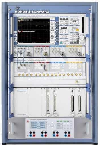
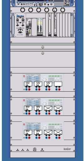
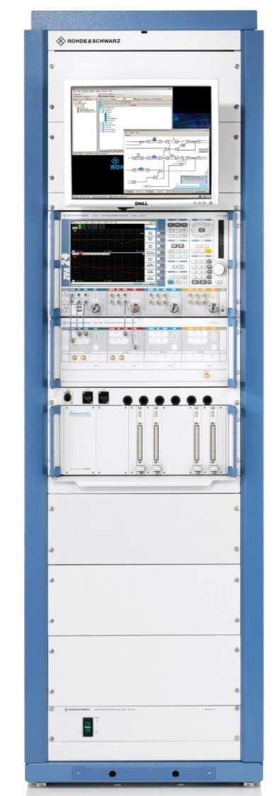
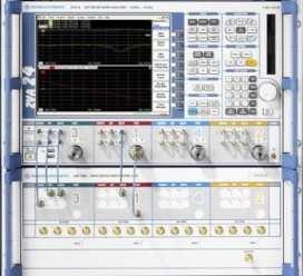
10 Automated Test e.g. TS6710

11 OSP-TRM High Customization ı Platform for high flexibility ı Combiners ı Pulse modulators ı Amplifiers ı Filters ı Multiport switches ı Controlled via sequencer


12 T/R Module Test Solution for Production ı ZVA + OSP-TRM ı Customization according to the requirements ı TX and RX test without reconnection of the T/R module ı Control Software with prepared test cases ı Control via external PC ı Digital control of the DUT ı Test of several DUTs in parallel


13 Test Suite TRM-LIB Features
14 Test Suite TRM-LIB DUT Control ı Support of devices without and with control (e.g. different DUT states) ı Digital control plugin programmed in C# for Communication with DUT Trigger generation ı Example C# source code enclosed, Adaptation by customer to his DUT Programming of the DUT actions to be carried out at each step Adaptation by customer or R&S
15 Requirements for the RF Equipment
16 High Performance for Intermodulation Trc1 b2 db Mag 15 db / Ref 0 dbm 1 b2 0 Mkr 2 Mkr Mkr GHz dbm Mkr MHz dbm Mkr MHz dbm Mkr GHz dbm >90 dbc IP3 40 dbm Mkr 3 Mkr Ch1 Arb Center 1 GHz Pwr 10 dbm Span 5 MHz
17 Typical Measurement Tasks for TR-Module Test ı Transmitter (TX) Transmission / reflection Low power Saturated power Pulse profile Harmonics Spurs ı Receiver (RX) Transmission / reflection Low power Saturated power Spurs Intermodulation Noise figure ı Number of states to be tested All combinations of phase and attenuator settings referred to basic setting Up to 1024 (5 bit) or (8 bit) combinations
18 High Output Power under all Conditions with Preamplifier No_OPTION a1(p1s) db Mag 5 db / Ref 0 dbm PCai Smo1 a1(p1s) M GHz dbm M GHz dbm no option Pumo a1(p1s) db Mag 5 db / Ref 0 dbm PCai Smo2 a1(p1s) GHz dbm M GHz dbm M2 pulse mod only Up to GHz with pulse modulator and combiner Ch1 fb Start 500 MHz a1(p1s) Pb 20 dbm Stop 20 GHz Ch2 fb Start 500 MHz Pb 20 dbm Stop 20 GHz Preamp_Pumo a1(p1s) db Mag 5 db / Ref 0 dbm PCai Sm 3 Pumo_Comb_PA a1(p1s) db Mag 5 db / Ref 0 dbm 4P GHz dbm M GHz dbm pulse mod + preamp M2 a1(p1s) GHz dbm M GHz dbm pulse mod + 0preamp + combiner M2 Ch3 fb Start 500 MHz Pb 10 dbm Stop 20 GHz Ch4 fb Start 500 MHz Pb 10 dbm Stop 20 GHz
19 Pulsed Measurement Capabilities ı Average pulse measurements Measurement versus power and frequency Receiver sampling time > pulse period Measures the average power of several pulses Measurement time / point time ı Point in pulse measurement (more accurate) Measurement versus power and frequency Receiver sampling time < pulse width Measures the peak power during one pulse ı Pulse profile measurement Measurement of the pulse versus time Receiver sampling time << pulse width (ZVA-K7) Measures the time dependent behavior during one pulse trigger delay trigger delay Measurement time / point data points Measurement time / point time time
20 Point in Pulse Measurement ı Frequency or power swept measurements ı Pulse width > sampling time ı Accurate power measurements during On time of the pulse ı Sampling time = (1..2) / IFBw ı Sampling MHz IFBw abt. 420 ns A t f 1 f 2 f 3 f 4 f 5 t τ f 1 f 2 f 3 f 4 f 5
21 Pulse Profile with R&S ZVA s Fast RAM-Mode
22 Pulse Profile with R&S ZVA s Fast RAM-Mode ı Measurement on one pulse with high sampling rate of 80 MHz and up to 30 MHz of bandwidth ı Time resolution 12.5 ns ı No loss of dynamic range by desensitization ı No re-calibration required, when pulse parameters are changed ı Measurements with single, double pulses and pulse trains possible ı Correction for delay caused by DUT with high electrical length

23 Internal Pulse Generators 2 independent pulse generators Minimum pulse width 12,5 ns Single pulse and pulse trains Individual delay, pulse width and polarity


24 Noise Figure Measurement with R&S ZVA Noise Figure Calculation: NF DUT SNR = 10log SNR input output P signal P input signaloutput = 10log 10log P noise P input noiseoutput : = CALdata : = NFmeas
25 Tests of the RX Path LNA for noise figure test 2 nd source for intermodulation combiner to generate 2-tone signal
26 Measurement Results RX Path S-parameters vs. frequency Intermodulation parameters vs. power S21 vs power Trc11 Trc12 Trc13 Trc14 S S21 S11 S22 S21 db Mag db Mag db Mag Phase 10 db / 10 db / 10 db / 1 / Ch1 fb Start 2 P1 GHz -30 dbm Trc8 Trc9 Trc10 Trc15 S Ref 0 db Ref 0 db Ref 0 db Ref C C C C GHz db UTO IM3UO IP3MO S21 db Mag db Mag db Mag db Mag Ch4 P1 Start -15 dbm 20 db / 20 db / 20 db / 1 db / Stop 3 GHz Ref 0 dbm Ref 0 dbm Ref 0 dbm Ref 30 db fb 2 GHz Trc2 UTO Trc4 IM3LO Trc7 IP3MO IP3MO Trc3 LTO Trc5 IM3UO Ch2 fb Start 2 P1 GHz -10 dbm PCal Off PCal Off PCal Off Ca? PCal Off dbm dbm 4 Stop 2 dbm NF Stop 3 GHz Trc6 b2(p1s) db Mag 15 db / Re 3 b2(p1s) Trc1 NF21 db Mag 2 db / Ref 0 db Ch5 fb Start 2 GHz P1-30 dbm Ch3 Arb Rec P1 Start -10 Stop dbm MHz GHz Cal NCal PCal Sm GHz db Stop 3 GHz Intermodulation parameters vs. frequency Intermodulation spectrum Noise figure
27 Test of the TX Path
28 Measurement Results TX Path S-parameter vs. frequency (pulsed ) Trc1 Trc2 Trc7 Trc8 S21 S21 S11 S22 S db Mag Phase db Mag db Mag 10 db / 3 / 10 db / 10 db / Ref 0 db Ref 25.6 Ref 0 db Ref 0 db Ca? Offs Ca? Smo Offs Ca? Offs Ca? Smo Offs GHz db GHz GHz db GHz db 1 Trc3 S21 Trc4 S21 Trc9 b2(p1s) S db Mag Phase db Mag 0.5 db / 1 / 2 db / Ref 28.5 db Ref Ref 18 dbm Cal Off Offs 2 Cal Off Smo O Offs S- parameter vs. power (pulsed ) Trc5 Trc10 Trc11 b2(p1s) S21 S21 db Mag db Mag Phase 10 db / 10 db / 45 / Ref 0 dbm Ref 0 db Ref 0 Cal Off Cal Off 3 Trc12 UTO Trc13 IM3UO Trc15 IP3MO db Mag db Mag db Mag 15 db / 15 db / 5 db / Ref -40 dbm Ref -40 dbm Ref 35 dbm 4 S21 vs time (pulse profile ) S21 TRG IM3UO Intermod. vs power
29 Measurement of complete DUT RX Path TX Path S21, S11 Trc11 Trc12 Trc14 S S21 S11 S21 db Mag db Mag Phase 10 db / 10 db / 2 / Ref 0 db Ref 0 db Ref 74 Ca? PCao Offs 1 Ca? PCao Offs Ca? PCao Smo Offs GHz db Trc2 Trc20 Trc21 S S12 S22 S12 db Mag 5 db / Ref 0 db db Mag 10 db / Ref 0 db db Mag 0.3 db / Ref 12.9 db Ch2 Ch2 Ch8 Ca? PCal Off 2 Ca? PCal Off Cal Off S12, S22 Intermod. Trc6 b2(p1s) db Mag 15 db / Ref 0 dbm Ch6 Trc9 IM3UO db Mag 20 db / Ref 0 dbm Ch PCal Off 3 PCal Off Trc4 S12 Phase 45 / Ref 0 Trc19 S12 db Mag 10 db / Ref 0 db S12 30 TRG Cal Off Cal Off µs Pulse profile Noise Fig Trc1 NF21 db Mag 2 db / Ref 5.5 db NF Cal NCal PCal Smo GHz db Trc17 b1(p4s) db Mag 10 db / Ref -50 dbm b1(p4s) GHz Intermod

30 T/R Module Test - Need for Accuracy and Speed ı Measurement of S-parameters acc. mag & phase ı Reason is test of accuracy of attenuator and phase shifter ı Required accuracy depends on resolution e.g. of digital phase shifter ı Phase shifters with 4..8 bits of resolution 6-bit phase shifter 360 / 64 = 5,625 resolution 8-bit phase shifter 360 / 256 = 1,4 resolution ı Typical T/R modules work with 5- or 6-bit phase shifters, new designs use 8-bit phase shifters ı Attenuator typ db resolution
31 Testing with high Speed Two different test approaches Performing CW Sweeps and switching the gain and attenuation states Used when frequency switching takes longer than switching DUT states Widely used so far Disadvantage: parameters have to be rearranged for documentation Performing frequency sweeps and switch after every sweep the DUT states Used when frequency switching time is shorter than switching DUT states Advantage: easy documentation of test results Prefered solution for the customer
32 Gain versus Frequency and Attenuation States


33 Switching Times of ZVA Switching Time ZVA CW Sweep Settings: ı CW frequency ı Meas bandwidth 10 MHz ı Time/Pt 2,5 us 5 GHz Switching time ZVA freq. sweep Settings: ı Start 6 GHz Stop 10 GHz ı Step width 1 MHz ı Meas bandwidth 100 khz ı Freq. switching time + sampling time 24 us
34 Proposed Scenario Example ı Switching time CW sweep ı Switching time freq. sweep ı Sampling time (100 khz) ı State switching time (sst) 3 us 12 us x us 12 us ı Test time CW sweep Tswcw (sst) + tsampl = 3 us + 12 us = 15 us ı Test time freq sweep tswfreq (sst) + tsmpl = 12 us +12 us = 24 us Frequency sweep is faster as soon as state switching time > 12 us Bottleneck for pulse measurements is pulse period
35 Typical Pulse Scenarios ı RX test in un-pulsed mode ı TX test in pulsed mode (point in pulse) ı Pulse width typically 10 us or wider Wide enough for measurement bandwidth of 100 khz When pulse width is wider, meas.-bandwdith can be reduced ı Duty cycle 10% or less Otherwise DUT will heat up Typically test time / point > 100 us in most cases VNA - switching time of frequency sweep is much faster than DUT - state switching time + pulse period state switching was a typical scenario in the past when VNA synthesizers were slow
36 Increase of Test Speed Multiple Measurements during one Pulse Problem: Long measurement time due to low pulse repetition rate and long ON - time Solution: Several measurements can happen during one pulse with pulse width of e.g.100 us ı Test time = switching time + sampling time ı Sampling time 100 khz IFBw 12 us; ı Freq switching time 12 us ı Frequency sweep: 12 us + 12 us = 24 us => 4 measurements during one pulse

37 Multiple Measurements during one Pulse ı Trigger signal for ZVA stops tsmapl before pulse modulator ON time stops ı Ensures data sampling during ON-time of the pulse ı Takes several ponts during one pulse ı Speeds up measurement in this example by factor 4
38 Tests of the TX Path Typical measurements tasks Low input power (..-20 dbm) for small signal High input power (5..10 dbm) for saturated power High output power e.g. 43 dbm Measurements under pulsed conditions Measurement in pulsed mode versus frequency, power and time Transmission (mag / phase) & reflection Different phase and gain settings, linear and saturated output power Pout versus Pin Intermodulation test with 2-tone signal
39 18.5 Test of TX Path small Signal special Challenges ı Forward S21 and S11 measurement in pulsed mode ı High accuracy specs (especially for 8 bit resolution) S21 < 1, < 0,1 db ı Pin for small signal test typically -20 dbm or even less ı Problem: High trace noise of S21 mag & phase ı Trace noise more critical than absolute accuracy ı Relative accuracy is necessary to compare the phase and magnitude states; ı Trace noise typically is the bottleneck Trc1 S21 db Mag 0.5 db / Ref 22 db 1 (Max) Trc2 b2(p1s) db Mag 0.5 db / Ref -0.5 dbm Trc3 a1(p1s) db Mag 0.5 db / Ref dbm Trc4 S21 Phase 1 / Ref S Trac Stat: Trc1 S21 Min: db 22.0 Max: db Pk-Pk: db 21.5 Trac Stat: Trc4 S21 Min: Max: Pk-Pk: Ch1 fb 1.7 GHz Pb -20 dbm Stop 801
40 Trace Noise without Optimazation ı Low power level on reference receiver, -20 dbm and lower for small signal measurement ı Meas. bandwidth 100 khz or higher for point in pulse measurement (depends on pulse width) ı Trace noise due to low power at reference receiver a1 wave at reference receiver Trc1 Trc2 Trc3 Trc4 S S21 b2(p1s) a1(p1s) S21 db Mag db Mag db Mag Phase 0.5 db / Ref 22 db 0.5 db / 0.5 db / 1 / 1 Ref -0.5 dbm Ref dbm Ref (Max) Trac Stat: Min: Max: Pk-Pk: Trac Stat: Min: Max: Pk-Pk: Trc1 S db db db Trc4 S b2 wave at reference receiver Ch1 fb 1.7 GHz Pb -20 dbm Stop 801


41 Solution for low Trace Noise for S21 Measurement ı Improve of sensitivity of reference receiver ı Optimize power level at the reference receivers Add attenuation in the source path e.g. by switchable attenuator and by using the loss of the modulator with increased source power
42 Setup for small Signal TX Measurement
43 Setup for small Signal TX Measurement - optimized
44 Optimized Trace Noise reference receiver low noise + optimized power level reference receiver low noise 1 1

45 Solution with OSP-TRM OSP-TRM
46 Phase Measurement ı Uncertainty ± 0,5 ı Total error (trace noise + systematic error) 1
47 TX path - saturated Power Measurement ı Trace noise uncritical compared to small signal Output power increased -> increase of step attenuation in b2 receiver Input power increased -> Removal of attenuation in reference path Use of reference arm of ZVAX coupler Reference power sufficient for good S/N ı Relative accuracy e.g. for 8-bit phase shifter better 1
48 Power Protection for 43 dbm ı ZVAX-TRM as well as OSP-TRM have high power couplers ı Receiver and source protection e.g. by isolators or attenuators required ı 43 dbm = 20 Watts ı Duty cycle 10 % ı Average power 23 dbm or 0,2 Watt ı 5 W attenuators (37 dbm) are sufficient
49 TX path - saturated Power Measurement

50 Solution with OSP-TRM OSP-TRM
51 Pulse Profile Measurement ı Use of averages for better S/N because of wide measurement bandwidth (>10 MHz)

52 TX Harmonics

53 Solution with OSP-TRM OSP-TRM
54 TX Spur Emission ı Harmonic measurement at specific frequencies ı Spur search over wide frequency range 10 GHz..20 GHz ı Typical settings Source in CW mode Receiver measures 2nd and 3rd harmonic and spurs Typically also pulsed with wide IF bandwidth
55 TX - Spur Emission ı SA functionlity of ZVA with software preselector Search range e.g. 7 GHz 15 GHz IFBW 200 khz 80 dbc dynamic range Meas time 9 sec
56 RX Path Small Signal Gain ı Test under un-pulsed conditions ı Switching of states ı Reflection, gain (mag&phase) ı Small signal input power -30 dbm and below ı High accuracy specs S12 < 0,5, < 0,05 db ı Full two port calibration necessary ı Problem: ı Low input power, high gain ı Low reference signal ı Low power in reverse direction due to high isolation. Trc2 Trc9 Trc a1(p1s) a2(p2s) a1(p1s) S21 db Mag db Mag db Mag 0.1 db / 0.1 db / 1 db / Ref dbm Ref dbm Ref db PCal Offs PCai Offs Ca? PCao Offs Trac Stat: Min: Max: Pk-Pk: Trc10 S Ch1 fb 2 GHz Pb -40 dbm Stop 801 Trc1 Trc8 S S12 S12 db Mag Phase 0.05 db / 0.5 / Ref db Ref 35.1 Ca? PCao Offs Ca? PCao Offs Trac Stat: Min: Max: Pk-Pk: Trac Stat: Min: Max: Pk-Pk: Trc1 S Trc8 S Ch1 fb 2 GHz Pb -40 dbm Stop db db db db db db dbm dbm db db 1 3
57 RX Path Small Signal Gain Solution ı Improvement of sensitivity by setting AGC amplifiers for a waves to low noise mode B wave receiver for forward direction has to remain in auto mode ı Increase of source power in the reference channel ı Use of internal coupler of ZVA ı Increase of power level for reverse measurement by 20 db or more.
58 RX small Signal Gain with and without Optimization ı Identical forward and reverse power ı 20 db higher reverse power Trc2 Trc9 Trc10 a2(p2s) db Mag 0.1 db / Ref dbm a1(p1s) db Mag 0.1 db / Ref dbm S21 db Mag 1 db / Ref db a1(p1s) PCal Offs PCai Offs Ca? PCao Offs Trac Stat: Min: Max: Pk-Pk: dbm dbm db Trc10 S db db db Trc2 Trc9 Trc10 a2(p2s) db Mag 0.1 db / Ref dbm a1(p1s) db Mag 0.1 db / Ref dbm S21 db Mag 1 db / Ref db a1(p1s) PCal Offs PCai Offs Ca? Pca? Offs Trac Stat: Min: Max: Pk-Pk: dbm dbm db Trc10 S db db db Ch1 fb 2 GHz Pb -40 dbm Stop 801 Trc1 Trc8 S S12 db Mag 0.05 db / Ref db S12 Phase 0.5 / Ref 35.1 Ca? PCao Offs Ca? PCao Offs Trac Stat: Min: Max: Pk-Pk: Trac Stat: Min: Max: Pk-Pk: Trc1 S db db db Trc8 S Ch1 fb 2 GHz Pb -40 dbm Stop db Ch1 fb 2 GHz Pb -40 dbm Stop 801 Trc1 Trc8 S S12 db Mag 0.05 db / Ref db S12 Phase 0.5 / Ref 35.1 Ca? Pca? Offs Ca? Pca? Offs Trac Stat: Min: Max: Pk-Pk: Trac Stat: Min: Max: Pk-Pk: Trc1 S db db db Trc8 S Ch1 fb 2 GHz Pb -40 dbm Stop db
59 RX Path - small Signal Gain Ref 2 In Meas 2 In Ref 1 In Port 2-40 dbm Ref 4 Out Ref 4 In 20 db Src 4 Out Src 4 In 20 db Rx Meas 1 In Ref 1 In 10 db Src 1Out Ref 3 Out Ref 3 In Src 3 Out Port 1-20 dbm -10 dbm Src 3 In ZVAX- TRM

60 ZVAX-TRM setup Use of internal ZVA coupler attenuator to boost output power
61 Solution with OSP-TRM OSP-TRM
62 RX Path Noise Figure

63 Solution with OSP-TRM OSP-TRM
64 End

 x x Power added efficiency TS6-K25 (with power supplies HMP4040 or TDK Lambda x Genesys)")
65 Test Suite TRM-LIB Functionality ı For solutions PC with ZVA + ZVAX-TRM or ZVA + OSP-TRM ı All main tests for TRMs of active devices covered: Test case Direction Tx Rx SW-Options: S-parameter over DUT states with Excel report x x TS6-K20 Compression point x x Pulse profile (rise time, fall time, power droop) x Spurious emissions x x TS6-K22 Noise figure x Out of band rejection x x TS6-PK20 Intermodulation (4 port ZVA) x x Power added efficiency TS6-K25 (with power supplies HMP4040 or TDK Lambda x Genesys) Harmonics x x or


66 R&S Test Sequencer for individual Test Plans Customer specific test sequences including Control of TRM module Implementation of required scope of tests Time optimization of test routines Test adaptations by customer or R&S Program code for test sequences delivered with the system Test Sequencer Test Report Generation
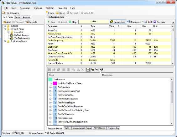
67 Real life test time: RX S-Parameter Measurement: DUT: RFcore core chip module TrmTxSParameter: Parameters StartFrequency: 9000 MHz StopFrequency: MHz Points: gain-phase-combinations Power: -30 dbm Bandwidth: 5 khz Measurement time: 12 seconds Resust files: Pass / fail analysis in report Statistical analysis Fast analysis by Excel graphics and measurement data (Gain vs Freq./ Phase vs. Freq. / Gain vs Phase / Phase vs Gain)
68 Real life test time: TX S-Parameter Measurement DUT: RFcore core chip module TrmTxSParameter: Parameters StartFrequency: 9000 MHz StopFrequency: 9500 MHz Points: phase states / 32 attenuation states all combinations Power: -17 dbm Bandwidth: 200 khz Resust files: Pass / fail analysis in report Statistical analysis Fast analysis by 4 Excel files with data and graphics (Gain vs Freq./ Phase vs. Freq. / Gain vs Phase / Phase vs Gain) Freqency = 9500 Att Phase Gain , , , ,9 4 14, , , ,4


69 R&S ctsvp: Fast programming of the Module DUT control: High Speed Digital Module up to 40 MHz pattern rate and programmable level for DUT control Large on board memory to save all DUT commands in advance. PXI LVDS digital waveform generator / analyzer Very fast setup of gain / phase, e.g. < 300us Real time evaluation of DUT response messages. Trigger of R&S ZVA24 for real time test. DMM
The high-end network analyzers from Rohde & Schwarz now include an option for pulse profile measurements plus, the new R&S ZVA 40 covers the
 GENERAL PURPOSE 44 448 The high-end network analyzers from Rohde & Schwarz now include an option for pulse profile measurements plus, the new R&S ZVA 4 covers the frequency range up to 4 GHz. News from
HP 71910A and 71910P Wide Bandwidth Receiver Technical Specifications
 HP 71910A and 71910P Wide Bandwidth Receiver Technical Specifications 100 Hz to 26.5 GHz The HP 71910A/P is a receiver for monitoring signals from 100 Hz to 26.5 GHz. It provides a cost effective combination
Improving the accuracy of EMI emissions testing. James Young Rohde & Schwarz
 Improving the accuracy of EMI emissions testing James Young Rohde & Schwarz Q&A Who uses what for EMI? Spectrum Analyzers (SA) Test Receivers (TR) CISPR, MIL-STD or Automotive? Software or front panel?
Model 7330 Signal Source Analyzer Dedicated Phase Noise Test System V1.02
 Model 7330 Signal Source Analyzer Dedicated Phase Noise Test System V1.02 A fully integrated high-performance cross-correlation signal source analyzer from 5 MHz to 33+ GHz Key Features Complete broadband
7000 Series Signal Source Analyzer & Dedicated Phase Noise Test System
 7000 Series Signal Source Analyzer & Dedicated Phase Noise Test System A fully integrated high-performance cross-correlation signal source analyzer with platforms from 5MHz to 7GHz, 26GHz, and 40GHz Key
MILLIMETER WAVE VNA MODULE BROCHURE
 MILLIMETER WAVE VNA MODULE BROCHURE General Information OML, founded in 1991, is an expert at millimeter wave (mm-wave) measurements. Our successful foundation is built on mm-wave S-parameter measurements,
RF (Wireless) Fundamentals 1- Day Seminar
 Fundamentals 1- Day Seminar") RF (Wireless) Fundamentals 1- Day Seminar In addition to testing Digital, Mixed Signal, and Memory circuitry many Test and Product Engineers are now faced with additional challenges: RF, Microwave and
RF (Wireless) Fundamentals 1- Day Seminar In addition to testing Digital, Mixed Signal, and Memory circuitry many Test and Product Engineers are now faced with additional challenges: RF, Microwave and
R&S ZVA-Zxx Millimeter-Wave Converters Specifications
 R&S ZVA-Zxx Millimeter-Wave Converters Specifications Data Sheet Version 19.00 CONTENTS Definitions... 3 General information... 4 Specifications... 5 Test port... 5 Source input (RF IN)... 5 Local oscillator
R3267/3273 Spectrum Analyzers
 R3267/3273 Spectrum Analyzers For 3rd-Generation Mobile Communications Present Digital Communication standards (W-CDMA, PDC, PHS, IS-136, GSM, DECT, cdmaone ) R3267/3273 New communication technologies
RF Semiconductor Test AXRF RF Port Upgrade Kits
 RF Semiconductor Test AXRF RF Port Upgrade Kits 2017 Datasheet The most important thing we build is trust Overview AXRF RF Port Upgrade Kits are designed to improve and extend the capability of an existing
RF Level Test System +20 dbm to 130 dbm
 NRVD Power Meter optional Therm. Sensor A B Power: >-15 dbm DUT (Signal Generator, Communication Tester) 1 MHz - 3.5/6 GHz +20 dbm... -130 dbm Diode Sensor Z4 Power: -15 to -40 dbm 6 db Power =< -40 dbm
R&S FSW-B512R Real-Time Spectrum Analyzer 512 MHz Specifications
 R&S FSW-B512R Real-Time Spectrum Analyzer 512 MHz Specifications Data Sheet Version 02.00 CONTENTS Definitions... 3 Specifications... 4 Level... 5 Result display... 6 Trigger... 7 Ordering information...
Keysight Technologies High Power Ampliier Measurements Using Nonlinear Vector Network Analyzer. Application Note
 Keysight Technologies High Power Ampliier Measurements Using Nonlinear Vector Network Analyzer Application Note Introduction High-power devices are common building blocks in RF and microwave communication
R&S ZVA-Zxx Millimeter-Wave Converters Specifications
 ZVA-Zxx_dat-sw_en_5214.2033.22_umschlag.indd 1 Data Sheet 13.00 Test & Measurement R&S ZVA-Zxx Millimeter-Wave Converters Specifications 28.01.2013 15:08:06 CONTENTS General information... 3 Definitions...
Advanced Test Equipment Rentals ATEC (2832)
") E stablished 1981 Advanced Test Equipment Rentals www.atecorp.com 800-404-ATEC (2832) Technical Datasheet Scalar Network Analyzer Model 8003-10 MHz to 40 GHz The Giga-tronics Model 8003 Precision Scalar
E stablished 1981 Advanced Test Equipment Rentals www.atecorp.com 800-404-ATEC (2832) Technical Datasheet Scalar Network Analyzer Model 8003-10 MHz to 40 GHz The Giga-tronics Model 8003 Precision Scalar
N5264A. New. PNA-X Measurement Receiver. Jim Puri Applications Specialist March Rev. Jan Page 1
 New N5264A PNA-X Measurement Receiver Jim Puri Applications Specialist March 2009 Page 1 Rev. 1 N5264A Measurement Receiver No connectors on front panel Page 2 Rev. 2 N5264A PNA-X Measurement Receiver
Basic RF Amplifier Measurements using the R&S ZNB Vector Network Analyzer and SMARTerCal. Application Note
 Basic RF Amplifier Measurements using a R&S ZNB Analyzer and SMARTerCal Mark Bailey 2013-03-05, 1ES, Version 1.0 Basic RF Amplifier Measurements using the R&S ZNB Vector Network Analyzer and SMARTerCal.
HMC7056. Block Upconverters / HPA's. Typical Applications. General Description. Features. Functional Block Diagram
 Typical Applications Features Compact Design Dual L Band Inputs Dual up conversion to ensure no phase inversion WR28 Output with Isolator PA Enable Digital Gain control Thermal Monitoring and Gain Compensation
OBSOLETE HMC7056. Block Upconverters / HPA's. Typical Applications. General Description. Features. Functional Block Diagram
 Typical Applications Features Compact Design Dual L Band Inputs Dual up conversion to ensure no phase inversion WR28 Output with Isolator PA Enable Digital Gain control Thermal Monitoring and Gain Compensation
Agilent 5345A Universal Counter, 500 MHz
 Agilent 5345A Universal Counter, 500 MHz Data Sheet Product Specifications Input Specifications (pulse and CW mode) 5356C Frequency Range 1.5-40 GHz Sensitivity (0-50 deg. C): 0.4-1.5 GHz -- 1.5-12.4 GHz
Modulated Wideband Power Amplifier
 1 Introduction The modulated wideband power amplifier is designed in order to create an inexpensive signal source for immunity testing of electronic building blocks and products. It is designed to be driven
OPTICAL MEASURING INSTRUMENTS. MS9710C 600 to 1750 nm OPTICAL SPECTRUM ANALYZER GPIB. High Performance for DWDM Optical Communications
 OPTICAL SPECTRUM ANALYZER 600 to 750 nm GPIB High Performance for DWDM Optical Communications The is a diffraction-grating spectrum analyzer for analyzing optical spectra in the 600 to 750 nm wavelength
How To Demonstrate Improved ACLR Dynamic Range With FSU and Noise Correction
 Product: Spectrum Analyzer FSU How To Demonstrate Improved ACLR Dynamic Range With FSU and Noise Correction Application Note This application note provides information about the ACLR measurement with noise
Calibrating the CMD Output Level for BER
 Ref Lvl -32 dbm -40-50 Marker 1 [T1] -35.50 dbm 5.000000 ms RBW 300 khz RF Att 0 db VBW 3 MHz SWT 5 ms Unit dbm 1 SUMMARY [T1] A RMS AVG -85.86 dbm SGL TRG -60-70 1RM -80 EXT -90-100 -110-120 -130 T1 T2
!Ill ~ 168. Model490 Dual Input, Dual Trace Automatic Peak Power Meter
 Model490 Dual Input, Dual Trace Automatic Peak Power Meter No other power meter can offer you these features: Help Mode: A Help Mode feature has been added to the Model 490 Automatic Peak Power Meter.
R-1550A Tempest Wide Range Receiver
 R-1550A Tempest Wide Range Receiver Product Brochure Version 0.2.00 April 2008 Dynamic Sciences International, Inc. R-1550A TEMPEST Wide Range Measurement Receiver Made specifically for TEMPEST testing
R&S ZNBT Vector Network Analyzer Specifications
 R&S ZNBT Vector Network Analyzer Specifications year Data Sheet Version 05.02 CONTENTS Definitions... 3 Measurement range... 4 Measurement speed... 6 Measurement accuracy of the R&S ZNBT8... 8 Measurement
FCPM-6000RC. Mini-Circuits P.O. Box , Brooklyn, NY (718)
") USB / Ethernet Integrated Frequency Counter & Power Meter 50Ω -30 dbm to +20 dbm, 1 MHz to 6000 MHz The Big Deal Automatically synchronized power & frequency measurements USB and Ethernet control Includes
USB / Ethernet Integrated Frequency Counter & Power Meter 50Ω -30 dbm to +20 dbm, 1 MHz to 6000 MHz The Big Deal Automatically synchronized power & frequency measurements USB and Ethernet control Includes
Orbital 4400X & 4400XI Series X-Band Ext Ref LNB
 Orbital 4400X & 4400XI Series X-Band Ext Ref LNB 4400XI Series, X-Band Ext Ref LNB with Universal 12-hole gasket input isolator MIL Spec MIL-STD-188-164A, 45 db internal filter How to order an Orbital
R&S FSW-K160RE 160 MHz Real-Time Measurement Application Specifications
 FSW-K160RE_dat-sw_en_3607-1759-22_v0200_cover.indd 1 Data Sheet 02.00 Test & Measurement R&S FSW-K160RE 160 MHz Real-Time Measurement Application Specifications 06.04.2016 17:16:27 CONTENTS Definitions...
Power Amplifier 1.5 MHz to 18 GHz, Split Bands. Now with smart digital monitoring and control options 19 Rack Mount Family Data Sheet
 General Description: These are wideband CW / Pulse Power Amplifiers, designed for pulse operation, and general-purpose, amplification. Using an advanced high power density LDMOS and GaN semiconductor processes,
AMIGO- 8VSB (ATSC) digital Modulator
 digital Modulator") - 8VSB (ATSC) digital Modulator With Linear & Non-Linear Pre-Distortion for HDTV Overview The LUMANTEK line of Solid State VHF/UHF 8VSB Digital Modulators offers an unparallel combination of features and
- 8VSB (ATSC) digital Modulator With Linear & Non-Linear Pre-Distortion for HDTV Overview The LUMANTEK line of Solid State VHF/UHF 8VSB Digital Modulators offers an unparallel combination of features and
1Chapter INTRODUCTION. This chapter describes the CST-5000 C-Band satellite terminal, referred to in this manual as the CST-5000 (Figure 1-1).
.") 1Chapter 1. INTRODUCTION This chapter describes the CST-5000 C-Band satellite terminal, referred to in this manual as the CST-5000 (Figure 1-1). Figure 1-1. CST-5000 Single Thread System Rev. 9 1 1 1.1
1Chapter 1. INTRODUCTION This chapter describes the CST-5000 C-Band satellite terminal, referred to in this manual as the CST-5000 (Figure 1-1). Figure 1-1. CST-5000 Single Thread System Rev. 9 1 1 1.1
SIR MICROWAVE WIDEBAND DSP RECEIVERS UP TO 26.5 GHz. WIDE FREQUENCY RANGE: GHz
 SIR-4002 MICROWAVE WIDEBAND DSP RECEIVERS UP TO 26.5 GHz WIDE FREQUENCY RANGE: 0.5 26.5 GHz FEATURES Advanced Front Panel Alphanumeric Display High Dynamic Range: In band Input IP3 > 0 dbm, NF< 15 db DSP
Broadcast Television Measurements
 Broadcast Television Measurements Data Sheet Broadcast Transmitter Testing with the Agilent 85724A and 8590E-Series Spectrum Analyzers RF and Video Measurements... at the Touch of a Button Installing,
Synthesized Block Up- and Downconverter Indoor / Outdoor
 Visit us at www.work-microwave.de Synthesized Block Up- and Downconverter Single / Dual / Triple Band Single / Dual Channel S-, C-, Ku-, K (DBS)-, Ka- and Q-band WORK Microwave s synthesized block converters
USB Smart Power Sensor
 50Ω -30 dbm to +20 dbm, 1 MHz to 8000 MHz The Big Deal Fast measurement speed, 10 msec USB HID device compatible with 32/64 Bit operating systems Includes Measurement Application GUI (Graphical User Interface)
R&S FSV-K40 Phase Noise Measurement Application Specifications
 FSV-K40_dat-sw_en_5213-9705-22_cover.indd 1 Data Sheet 02.00 Test & Measurement R&S FSV-K40 Phase Noise Measurement Application Specifications 06.10.2014 14:51:49 CONTENTS Specifications... 3 Ordering
Advanced Test Equipment Rentals ATEC (2832)
") Established 1981 Advanced Test Equipment Rentals www.atecorp.com 800-404-ATEC (2832) This product is no longer carried in our catalog. AFG 2020 Characteristics Features Ordering Information Characteristics
Established 1981 Advanced Test Equipment Rentals www.atecorp.com 800-404-ATEC (2832) This product is no longer carried in our catalog. AFG 2020 Characteristics Features Ordering Information Characteristics
USB Mini Spectrum Analyzer User Manual PC program TSA For TSA5G35 TSA4G1 TSA6G1 TSA12G5
 USB Mini Spectrum Analyzer User Manual PC program TSA For TSA5G35 TSA4G1 TSA6G1 TSA12G5 Triarchy Technologies, Corp. Page 1 of 17 USB Mini Spectrum Analyzer User Manual Copyright Notice Copyright 2013
Keysight Technologies High-Power Measurements Using the E5072A ENA Series Network Analyzer. Application Note
 Keysight Technologies High-Power Measurements Using the E5072A ENA Series Network Analyzer Application Note Table of Contents Coniguration 1 Standard 2-port coniguration... 3 Coniguration 2 Measurements
VXIbus Microwave Downconverter
 1313B Phase Matrix, Inc ṬM Instruments You Can Count On VXIbus Microwave Downconverter High-Performance Downconversion For Analysis of Microwave Signals 1 MHz to 26.5 GHz Frequency Range -135 to +30 dbm
4400X Series. Orbital. X-Band Ext Ref LNB. MIL Spec MIL-STD A, 45 db internal filter LNB630S-500X-WN60-G12. Orbital Features: Orbital Specs:
 Orbital 4400X Series X-Band Ext Ref LNB 4400X Series, X-Band Ext Ref LNB with Universal 12-hole gasket input isolator. MIL Spec MIL-STD-188-164A, 45 db internal filter How to order an Orbital 4400X Series
Agilent PSA Series Spectrum Analyzers Data Sheet
 Agilent PSA Series Spectrum Analyzers Data Sheet E4443A E4445A E4440A E4446A E4448A 3 Hz to 6.7 GHz 3 Hz to 13.2 GHz 3 Hz to 26.5 GHz 3 Hz to 44 GHz 3 Hz to 50 GHz The Agilent PSA series offers high-performance
Agilent 8560 E-Series Spectrum Analyzers
 Agilent 8560 E-Series Spectrum Analyzers Data Sheet 8560E 30 Hz to 2.9 GHz 8561E 30 Hz to 6.5 GHz 8562E 30 Hz to 13.2 GHz 8563E 30 Hz to 26.5 GHz 8564E 30 Hz to 40 GHz 8565E 30 Hz to 50 GHz 8565E SPECTRUM
SIDC-6003 MICROWAVE WIDEBAND DOWNCONVERTER / TUNER UP TO
 SIDC-6003 MICROWAVE WIDEBAND DOWNCONVERTER / TUNER UP TO 26.5 GHz WIDE FREQUENCY RANGE: 0.5-26.5 GHz FEATURES High Dynamic Range Fast Switching Synthesizer with 10 Hz Tuning Resolution Excellent Phase
Inmarsat Downconverter Narrowband Downconverter
 Visit us at www.w ork-microw ave.de Inmarsat Downconverter Narrowband Downconverter L-Band to 70/140 MHz S-Band to 725 MHz 140 MHz to 15 MHz Single Conversion Dual Channel Converters also available. These
Vector Network Analyzer TTR503A/TTR506A USB Vector Network Analyzer Preliminary Datasheet. Subject to change.
 Vector Network Analyzer TTR503A/TTR506A USB Vector Network Analyzer Preliminary Datasheet. Subject to change. Applications Academic/Education Design, development and manufacturing of passive and active
CONTENTS 1. GENERAL INFORMATION INTRODUCTION PRODUCT INFORMATION DESCRIPTION OF TESTS CHANNEL BANDWIDTH...
 Test Report Number : GETEC-E3-09-083 Page 2 / 33 CONTENTS. GENERAL INFORMATION...4 2. INTRODUCTION...5 3. PRODUCT INFORMATION...6 3. DESCRIPTION OF EUT...6 3.2 SUPPORT EQUIPMENT / CABLES USED...7 3.3 MODIFICATION
Features. = +25 C, As a Function of LO Drive
 Typical Applications v.411 The is ideal for: Basestations, Repeaters & Access Points WiMAX, WiBro & Fixed Wireless Portables & Subscribers PLMR, Public Safety & Telematics Functional Diagram Features Passive
USB Mini Spectrum Analyzer User Manual TSA Program for PC TSA4G1 TSA6G1 TSA8G1
 USB Mini Spectrum Analyzer User Manual TSA Program for PC TSA4G1 TSA6G1 TSA8G1 Triarchy Technologies Corp. Page 1 of 17 USB Mini Spectrum Analyzer User Manual Copyright Notice Copyright 2013 Triarchy Technologies,
R&S FPC1000 Spectrum Analyzer Specifications
 R&S FPC1000 Spectrum Analyzer Specifications year Data Sheet Version 01.00 CONTENTS Definitions... 3 Specifications... 4 Frequency... 4 Sweep time... 4 Bandwidth... 4 Level... 5 Trigger functions... 6
SMS3000X Series Spectrum Analyzer
 Data Sheet SMS3000X Series Spectrum Analyzer SMS3032X SMS3021X General Description SMS3000X series spectrum analyzer has a frequency range from 9 khz up to 2.1 GHz/3.2 GHz, it is light weight and small
Satellite Up- and Downconverter Indoor / Outdoor
 Visit us at www.work-microwave.de Satellite Up- and Downconverter Indoor / Outdoor Single / Dual / Triple Band Single / Dual Channel S-, C-, X-, Ku-, K (DBS)-, Ka-, and Q-band WORK Microwave s satellite
R&S HF907DC SHF Downconverter Specifications
 Radiomonitoring & Radiolocation Data Sheet 01.03 R&S HF907DC SHF Downconverter Specifications CONTENTS Definitions... 3 Specifications... 4 Frequency conversion... 4 Input and output properties... 4 Rechargeable
R&S FPS-K18 Amplifier Measurements Specifications
 R&S FPS-K18 Amplifier Measurements Specifications Data Sheet Version 02.00 Specifications The specifications of the R&S FPS-K18 amplifier measurements are based on the data sheet of the R&S FPS signal
News from Rohde&Schwarz Number 195 (2008/I)
") BROADCASTING TV analyzers 45120-2 48 R&S ETL TV Analyzer The all-purpose instrument for all major digital and analog TV standards Transmitter production, installation, and service require measuring equipment
BROADCASTING TV analyzers 45120-2 48 R&S ETL TV Analyzer The all-purpose instrument for all major digital and analog TV standards Transmitter production, installation, and service require measuring equipment
R&S ZND Vector Network Analyzer Specifications
 R&S ZND Vector Network Analyzer Specifications year Test & Measurement Data Sheet 02.01 CONTENTS Definitions... 3 Measurement range... 4 Measurement speed... 5 Measurement accuracy... 7 Effective system
RS Pro SPECTRUM ANALYZER SSA3000X SERIES
 Product Datasheet ENGLISH Stock No: 1236443 (RSSA3021X) 1236444 (RSSA3032X) RS Pro SPECTRUM ANALYZER SSA3000X SERIES Features and Benefits RSSA3032X XX RSSA3021X All-Digital IFTechnology Frequency Range
Be ahead in 5G. Turn visions into reality.
 e n e Be ahead in 5G. Turn visions into reality. 5G test solutions ) www.rohde-schwarz.com/5g 20937_003_5G Flyer_3606-8620-32_V0100_170310.indd 3 5G test challenge: Measuring new 5G systems 5G challenges
Datasheet SHF A
 SHF Communication Technologies AG Wilhelm-von-Siemens-Str. 23D 12277 Berlin Germany Phone +49 30 772051-0 Fax ++49 30 7531078 E-Mail: sales@shf.de Web: http://www.shf.de Datasheet SHF 19120 A 2.85 GSa/s
Extension kit for R&S Vector Network Analysers
 NM300 Data Sheet September 2012 Extension kit for R&S Vector Network Analysers Characterisation of Nonlinear RF/HF Components in Time and Frequency domain Extension kit for R&S Vector Network Analysers
R&S ZNBT Vector Network Analyzer Network analysis with up to 24 test ports
 R&S ZNBT Vector Network Analyzer Network analysis with up to 24 test ports ZNBT_bro_en_3606-9727-12_v0300.indd 1 Product Brochure 03.00 Test & Measurement year 11.07.2016 14:59:23 R&S ZNBT Vector Network
Spectrum Analyzer 1.6 GHz 3 GHz R&S HMS-X
 HMS-X_bro_de-en_3607-0181-3X_v0200.indd 1 Product Brochure 02.00 Test & Measurement Spectrum Analyzer 1.6 GHz 3 GHz R&S HMS-X 15.03.2016 15:24:06 1 Basic Unit + 3 Options Key facts Frequency range: 100
Digital Storage Oscilloscopes 2550 Series
 Data Sheet Digital Storage Oscilloscopes 2550 Series The 2550 series digital storage oscilloscopes provide high performance and value in 2-channel and 4-channel configurations. With bandwidth from 70 MHz
Application Note DT-AN-2115B-1. DTA-2115B Verification of Specifations
 DTA-2115B Verification of Specifations APPLICATION NOTE January 2018 Table of Contents 1. Introduction... 3 General Description of the DTA-2115B... 3 Purpose of this Application Note... 3 2. Measurements...
TEST REPORT No
 D-PL-12076-01-00 TEST REPORT No. 3-20835062 Applicant Equipment under test Kathrein Automotive GmbH & Co. KG LTE Kompensator US; 6803145-01 218898-10 50110260 FCC-ID: 2ACC7LTECOMPB0 Test Standard(s) FCC
Tests on 3G-Base Stations to TS with FSIQ and SMIQ
 Products: FSIQ, SMIQ Tests on 3G-Base Stations to TS 25.141 with FSIQ and SMIQ This application note describes how to measure the various WCDMA signals which are used for transmitter tests on FDD base
SIDC-5009 Series VHF/UHF WIDEBAND TUNER/CONVERTER. FREQUENCY RANGE: 20 to 3000 MHz
 SIDC-5009 Series VHF/UHF WIDEBAND TUNER/CONVERTER FREQUENCY RANGE: 20 to 3000 MHz High Dynamic Range Enables the End User to Reject Blocking Signals Often Undetected by Less Sensitive Tuners High Dynamic
EUTRA/LTE Downlink Specifications
 Test & Measurement Data Sheet 03.00 EUTRA/LTE Downlink Specifications R&S FS-K100PC/-K102PC/-K104PC R&S FSV-K100/-K102/-K104 R&S FSQ-K100/-K102/-K104 R&S FSW-K100/-K102/-K104 CONTENTS Definitions... 3
JD725A Cable and Antenna Analyzer - Dual Port
 COMMUNICATIONS TEST & MEASUREMENT SOLUTIONS JD725A Cable and Antenna Analyzer - Dual Port Key Features Portable and lightweight handheld instrument Built-in wireless frequency bands as well as the most
Introduction This application note describes the XTREME-1000E 8VSB Digital Exciter and its applications.
 Application Note DTV Exciter Model Number: Xtreme-1000E Version: 4.0 Date: Sept 27, 2007 Introduction This application note describes the XTREME-1000E Digital Exciter and its applications. Product Description
Advanced Techniques for Spurious Measurements with R&S FSW-K50 White Paper
 Advanced Techniques for Spurious Measurements with R&S FSW-K50 White Paper Products: ı ı R&S FSW R&S FSW-K50 Spurious emission search with spectrum analyzers is one of the most demanding measurements in
SIDC-6005 MICROWAVE WIDEBAND DOWNCONVERTER / TUNER UP TO
 SIDC-6005 MICROWAVE WIDEBAND DOWNCONVERTER / TUNER UP TO 18 GHz WIDE FREQUENCY RANGE: 0.5-18 GHz FEATURES High Dynamic Range Fast Switching Synthesizer with 10 Hz Tuning Resolution Excellent Phase Noise
HMC7053. Block Upconverters. Typical Applications. General Description. Features. Functional Block Diagram. Satellite communications.
 Typical Applications Satellite communications Commercial Features Compact Design Dual L Band Inputs Dual Upconversion to ensure no phase inversion SMA(F) Input Connectors K(F) Output Connector Digital
11 GHz MDD FIBER OPTIC LINK FEATURES TYPICAL APPLICATIONS
 11 GHz MDD FIBER OPTIC LINK FEATURES Small size Bandwidth to 11 GHz Plug-in optical connector No external control circuits required Transimpedance amplifier in both transmitter and receiver Custom transmitter
Agilent 4-Port PNA-L Microwave Network Analyzer
 Agilent 4-Port PNA-L Microwave Network Analyzer N523A 3 khz to 13.5, 2 GHz Data Sheet Note: Specification information in this document is also available within the PNA-L network analyzer s internal Help
OBSOLETE HMC215LP4 / 215LP4E. GaAs MMIC MIXER w/ INTEGRATED LO AMPLIFIER, GHz. Typical Applications. Features. Functional Diagram
 v1.111 LO AMPLIFIER, 1.7-4. GHz Typical Applications The HMC215LP4 / HMC215LP4E is ideal for Wireless Infrastructure Applications: PCS / 3G Infrastructure Base Stations & Repeaters WiMAX & WiBro ISM &
RF-LAMBDA LEADER OF RF BROADBAND SOLUTIONS
 Clarke & Severn Electronics Ph + Email sales@clarke.com.au www.cseonline.com.au RF-LAMBDA LEADER OF RF BROADBAND SOLTIONS RFSPTA0GSB SB Control Absorptive Coaxial SPT Switch - GHz Electrical Specifications,
Analyze Frequency Response (Bode Plots) with R&S Oscilloscopes Application Note
 with R&S Oscilloscopes Application Note") Analyze Frequency Response (Bode Plots) with R&S Oscilloscopes Application Note Products: R&S RTO2002 R&S RTO2004 R&S RTO2012 R&S RTO2014 R&S RTO2022 R&S RTO2024 R&S RTO2044 R&S RTO2064 This application
Analyze Frequency Response (Bode Plots) with R&S Oscilloscopes Application Note Products: R&S RTO2002 R&S RTO2004 R&S RTO2012 R&S RTO2014 R&S RTO2022 R&S RTO2024 R&S RTO2044 R&S RTO2064 This application
R&S HA-Z24E External Preamplifier 1 GHz to 85 GHz Specifications
 R&S HA-Z24E External Preamplifier 1 GHz to 85 GHz Specifications Data Sheet Version 01.01 Definitions General Product data applies under the following conditions: Three hours storage at ambient temperature
Agilent CSA Spectrum Analyzer N1996A
 Agilent CSA Spectrum Analyzer N1996A Demonstration Guide Introduction This step-by-step demo guide will help you explore the unprecedented value of the Agilent CSA spectrum analyzer for meeting your design,
Application Note DT-AN DTU-315 Verification of Specifications
 DTU-315 Verification of Specifications APPLICATION NOTE January 2018 Table of Contents 1. Introduction... 3 General Description of the DTU-315... 3 Purpose of this Application Note... 3 2. Measurements...
SIGFOX END- PRODUCT RADIATED TEST PLAN FOR SIGFOX READY TM CERTIFICATION
 May 23 th 2018 SIGFOX END- PRODUCT RADIATED TEST PLAN FOR SIGFOX READY TM CERTIFICATION Public use Revision History Revision Number Date Author Change description 0.1 August 15 th, 2017 B.Ray Initial spec
Features. = +25 C, As a Function of LO Drive. LO = +10 dbm IF = 100 MHz
 v4.6 HMC218MS8 / 218MS8E Typical Applications The HMC218MS8 / HMC218MS8E is ideal for: Basestations, Repeaters & Access Points WiMAX, WiBro & Fixed Wireless Portables & Subscribers PLMR, Public Safety
LadyBug Technologies, LLC LB5908A True-RMS Power Sensor
 LadyBug Technologies, LLC LB5908A True-RMS Power Sensor LB5908ARev8 LadyBug Technologies www.ladybug-tech.com Telephone: 707-546-1050 Page 1 LB5908A Data Sheet Key PowerSensor+ TM Specifications Frequency
8500A. Advanced Test Equipment Rentals ATEC (2832) channel capability. For tests on pulse mod- SERIES PEAK POWER METERS
 channel capability. For tests on pulse mod- SERIES PEAK POWER METERS") Established 1981 Advanced Test Equipment Rentals www.atecorp.com 800-404-ATEC (2832) Page 1 of 5 8500A The Giga-tronics 8500A Series Peak Power Meters THE ACCURACY STANDARD channel capability. For tests
Established 1981 Advanced Test Equipment Rentals www.atecorp.com 800-404-ATEC (2832) Page 1 of 5 8500A The Giga-tronics 8500A Series Peak Power Meters THE ACCURACY STANDARD channel capability. For tests
LPT-3000 Remote User s Guide (LPT-3000R) LP Technologies
 LP Technologies") 99 Washington Street Melrose, MA 02176 Phone 781-665-1400 Toll Free 1-800-517-8431 Visit us at www.testequipmentdepot.com LPT-3000 Remote User s Guide (LPT-3000R) LP Technologies 1 Table of Contents Chapter
99 Washington Street Melrose, MA 02176 Phone 781-665-1400 Toll Free 1-800-517-8431 Visit us at www.testequipmentdepot.com LPT-3000 Remote User s Guide (LPT-3000R) LP Technologies 1 Table of Contents Chapter
RF Record & Playback MATTHIAS CHARRIOT APPLICATION ENGINEER
 RF Record & Playback MATTHIAS CHARRIOT APPLICATION ENGINEER Introduction Recording RF Signals WHAT DO WE USE TO RECORD THE RF? Where do we start? Swept spectrum analyzer Real-time spectrum analyzer Oscilloscope
MTP200B WLAN / BT LE Tester
 www.tescom.co.kr MTP200B WLAN / BT LE Tester Introduction Tescom s MTP200B is a non-signaling test-based WLAN or BT LE (Low Energy) tester. As one-body equipment incorporating both Signal Generator and
8650A SERIES UNIVERSAL POWER METERS
 8650A SERIES UNIVERSAL METERS 8650A SERIES UNIVERSAL METERS The Capabilities to Test Today s Sophisticated Communications Systems TIME BURST AVERAGE The Giga-tronics 8650A Series Universal Power Meters
SatLabs Recommendation for a Common Inter-Facility Link for DVB-RCS terminals
 SatLabs Recommendation for a Common Inter-Facility Link for DVB-RCS terminals Version 1.6-06/01/2005 This document is the result of a cooperative effort undertaken by the SatLabs Group. Neither the SatLabs
Wide Band Power Amplifier 6GHz~12GHz. Parameter Min. Typ. Max. Units Frequency Range 6 12 GHz Gain db Gain Flatness ±2.0 ±3.
 RFLPAGGA Wide Band Power Amplifier ~ Electrical Specifications, TA = +⁰C, Vcc = +V Features Gain: db Typical Output power: +dbm Typical High PdB: +dbm Typical Supply Voltage: +V Ohm Matched Input / Output
Spectrum Analyzer 1.6 GHz 3 GHz HMS-X
 Spectrum Analyzer 1.6 GHz 3 GHz 1 Basic Unit + 3 Options Your Spectrum Analyzer Key facts Frequency range: 100 khz to 1.6 GHz/3 GHz* 1 Spectral purity greater than -100 dbc/hz (at 100 khz) SWEEP from 20
Application Note 5098
 LO Buffer Applications using Avago Technologies ABA-3X563 Silicon Amplifiers Application Note 5098 Introduction An oscillator or a voltage-controlled oscillator (VCO) is usually buffered with an external
R&S FSMR Measuring Receiver Specifications
 Test & Measurement Data Sheet 09.00 R&S FSMR Measuring Receiver Specifications CONTENTS Specifications... 3 Frequency...3 Measuring receiver... 3 Frequency counter...3 RF power...4 RF level (tuned receiver)...5
RF-LAMBDA LEADER OF RF BROADBAND SOLUTIONS
 LEADER OF RF BROADBAND SOLTIONS Clarke & Severn Electronics Ph + Email sales@clarke.com.au www.clarke.com.au RFSPTA000GSB Absorptive Coaxial SPT Switch 0. - 0GHz Electrical Specifications, TA = + C, SB
Measurements on GSM Base Stations According to Rec
 Measurements on GSM Base Stations According to Rec. 11.20 Application Note 1EF23_0L Subject to change 10 September 96, Josef Wolf / Roland Minihold Products: FSE incl. Option FSE-B7 1 Introduction The
Orbital 694XA Series. Ka BAND EXTERNAL REFERENCE LNB with rear anchor posts. Wide range of Frequencies and Bandwidths LNB 1855R 1000 XA-WN60
 Orbital 694XA Series Ka BAND EXTERNAL REFERENCE LNB with rear anchor posts Wide range of Frequencies and Bandwidths How to order an Orbital 694XA Series Ka Ext Ref LNB Frequencies (GHz): LO Input Output
Instrumentation Grade RF & Microwave Subsystems
 Instrumentation Grade RF & Microwave Subsystems PRECISION FREQUENCY TRANSLATION SignalCore s frequency translation products are designed to meet today s demanding wireless applications. Offered in small