DELSYS. Bagnoli TM EMG System User s Guide
|
|
|
- Adele Wilcox
- 6 years ago
- Views:
Transcription


1 DELSYS Bagnoli TM EMG System User s Guide
2 Bagnoli TM EMG System User s Guide PM-B05 Copyright by Delsys Incorporated Specifications and procedures outlined in this document are subject to change without notice. The Delsys Logo, EMGworks, and Myomonitor are Registered Trademarks of Delsys Incorporated. MAN
3
4 Important Information... 1 Intended Use... 1 Contraindications... 1 Technical Service and Support... 1 Warnings and Precautions... 2 Device Information... 3 Disclaimer... 4 Limited Warranty... 4 Bagnoli EMG System... 5 Bagnoli System Components... 6 Main Amplifier Unit... 6 DE-2.1 Single Differential Surface EMG Sensor... 7 Input Modules... 8 Input Cable... 8 InterModule Cable (Bagnoli-16 Only)... 9 EMG Accessory Kit... 9 Power Supply EMGworks Package (Optional) Getting Started with the Bagnoli System Connecting the Power Supply Connecting the Output Signals HD68 Connector for EMGworks Package BNC Connectors Connecting the Input Modules Using the Sensors Orienting the EMG Sensors on the Skin Using the Delsys Adhesive Sensor Interface Connecting the Reference Electrodes Turning the System On Selecting Appropriate Amplifier Gains Beginning Data Acquisition HD68 Connector for EMGworks Package BNC Connectors Signal Quality Assurance Features Saturation Level Detector Line Interference Detector Audible Buzzer Alarm Additional Bagnoli Hardware Features Trigger Port HD68 Connector Pinout Maintenance and Care of the Bagnoli System Main Amplifier Unit and Input Modules DE Series Surface EMG Sensors... 25
5 Specifications Main Amplifier Unit (Common) Bagnoli-4 Main Amplifier Unit Bagnoli-8 Main Amplifier Unit Bagnoli-16 Main Amplifier Unit SC-P02 / SC-P03 Power Supply for Bagnoli Systems DE 2.1 Single Differential Surface EMG Sensor Input Module Input Cable InterModule Cable Reference Electrode Cable Trigger Port* Trigger Port Timing Diagram Component References... 30
6 Important Information Important Information Intended Use The Bagnoli TM EMG Systems are biofeedback devices intended for research, investigational and scholarship purposes only. Delsys products are not intended for measurement purposes or for use in the treatment and diagnosis of disease. Interpretation of the EMG signal by a qualified professional is required. Rx ONLY Contraindications DO NOT USE on Patients with implanted electronic devices of any kind, including cardiac pace-makers or similar assistive devices, electronic infusion pumps, and implanted stimulators. DO NOT USE on irritated skin or open wounds. DO NOT USE on Patients with allergies to Silver. Technical Service and Support For information and assistance visit our web site at: Contact us at: support@delsys.com tel: (508)


7 Important Information Warnings and Precautions Consult all accompanying documents for precautionary statements and other important information. Consult accompanying user s guide for detailed instructions. Keep the device dry. The presence of liquids may compromise the safety features of the device. Handle with care. Sensitive electronic device. Avoid static discharges. Do not operate or store near strong electrostatic, electromagnetic, magnetic or radioactive fields. Interference from external sources may decrease the signal-tonoise ratio or result in corrupted data. This device may cause electrical disturbances in sensitive equipment within its operating environment. Connect only to Delsys-approved devices. Connecting a patient to high-frequency surgical equipment while using Delsys EMG systems may result in burns at the site of the EMG sensor contacts. Immediately discontinue device use if skin irritation or discomfort occurs. Immediately discontinue device use if a change in the device s performance is noted. Contact Delsys technical support for assistance. Delsys Inc. guarantees the safety, reliability, and performance of the equipment only if assembly, modifications and repairs are carried out by authorized technicians; the electrical installation complies with the appropriate requirements; and the equipment is used in accordance with the instructions for use. 2 Bagnoli TM EMG System User s Guide

 Do not dispose this")

 Serial Number (appears")
8 Important Information Device Information Complies with Requirements put forth by the Medical Device Directive 93/42/EEC. Class I device, Annex VII. Type BF device (IEC ). Isolated device, (Class II, IEC ) Do not dispose this product with house waste. Contact Delsys Inc. for instructions on responsibly disposing this device. This product should not be mixed with other commercial wastes. Date of Manufacturing (appears on device) Serial Number (appears on device) Authorized Representative Manufacturer 3
9 Important Information Disclaimer DELSYS INC. makes no warranties, express or implied, as to the quality and performance of this product including but not limited to, any implied warranty of applicability for other than research uses by qualified individuals. DELSYS INC. shall not be liable to any person for any medical expenses or any direct or consequential damages resulting from any defect, failure or malfunction, whether a claim for such damages is based upon theory of warranty, contract, tort or otherwise. No representative, agent, or licensed practitioner is authorized to waive this disclaimer. DELSYS INC. makes no diagnosis or prescription by virtue of anything about this product. Limited Warranty The Bagnoli TM EMG Systems are warranted against failure of materials and workmanship for a period of 1 year from the date of delivery, provided that the product is given proper care and has not been subject to abuse during this period. This warranty is in lieu of all other warranties expressed or implied. Operation of this device outside specifications determined by DELSYS INC. or use with any other input devices other than DELSYS INC. sensors constitute an invalidation of this limited warranty. This warranty is not transferable. 4 Bagnoli TM EMG System User s Guide


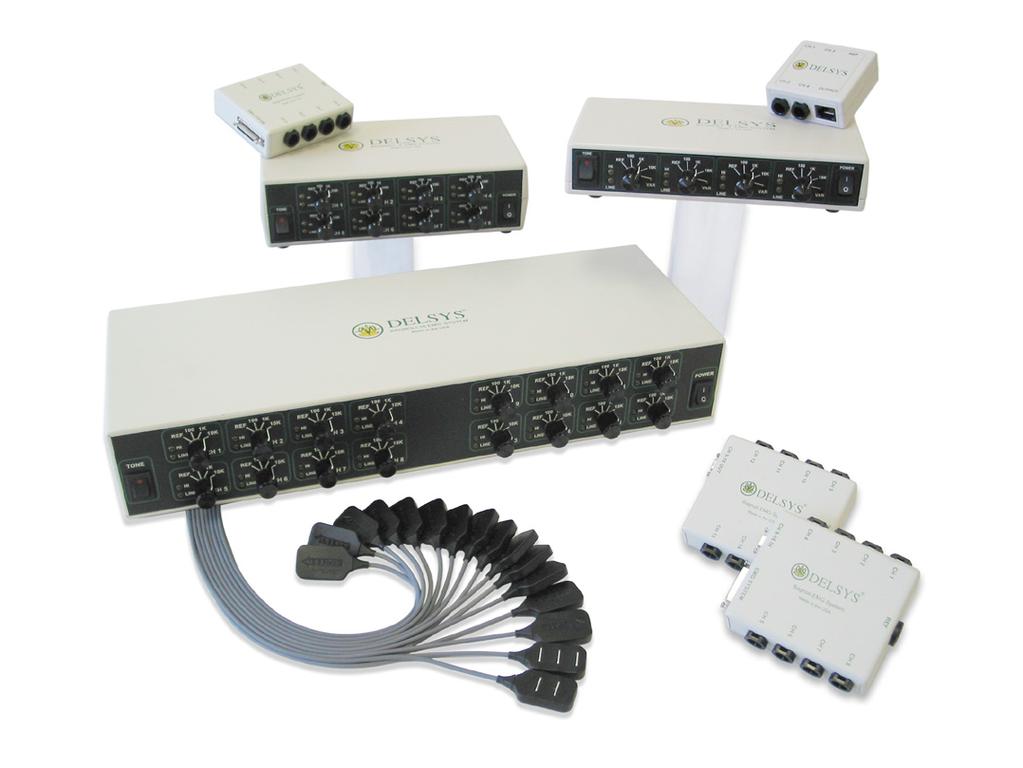
10 Bagnoli EMG System Bagnoli EMG System The Bagnoli EMG Systems are available in 4, 8, and 16 channel models, and are designed to make the acquisition of EMG signals hassle-free and reliable. These units produce conditioned, isolated, analog signals which can be readily connected to all Motion Capture or stand-alone data acquisition systems. Selectable gains, built-in signal quality checks, and ultralight parallelbar sensors make Bagnoli EMG Systems practical in both lab and field environments. Figure 1. Bagnoli-16 EMG System 1 Sensor 4 Input Module Cable 2 Main Amplifier 5 InterModule cable 3 Input Module(s) 6 International Power Supply Figure 2. Bagnoli-8 (left) and Bagnoli-4 (right) EMG Systems. 5

11 Bagnoli System Components Bagnoli System Components Main Amplifier Unit This desktop unit supplies power to the EMG and Biosignal Sensors, and provides conditioning and management of the detected signals to produce robust outputs. Each channel has a selectable gain which can be set to a factor of 100, 1000 or At these gain settings, the Main Amplifier Unit filters the signals to a bandwidth between 20 Hz and 450 Hz and checks for excessive amounts of line interference as well as channel clipping due to over-amplified signals. The presence of these errors is signaled via yellow LEDs and through a userenabled audio buzzer alarm. There is also an AUX setting for each channel, which is designed for the use of Delsys Biosignal Sensors. The analog channel outputs can be accessed via convenient BNC connectors or connected directly to a data acquisition system via the high-density D-Sub (HD68) connector located on the rear panel. A triggering port located on the rear panel allows the user to start and stop data acquisition with an external signal or to output a trigger signal to synchronize other data collection equipment. Figure 3. Bagnoli-16 Main Amplifier Unit 6 Bagnoli TM EMG System User s Guide

12 Bagnoli System Components DE-2.1 Single Differential Surface EMG Sensor The DE 2.1 EMG Sensor subtracts EMG potentials detected at two distinct locations on the surface of the skin directly above an active muscle. The EMG potentials are always measured with respect to the electric potential of a neutral site located away from the EMG muscle source. This potential is detected by the Reference Electrode. The sensor is designed using a parallel-bar contact geometry for ensuring signal stability, repeatability between recordings and optimal frequency content representation. This versatile sensor is well-suited for most EMG applications and ideal for both large and small muscles. Figure 4. DE-2.1 Single Differential Surface EMG Sensor. The surface EMG signal is the result of the potential difference between V 1 and V 2 on the skin surface. The sensor housing is constructed from durable polycarbonate and completely sealed. It is also internally shielded to reject ambient electrical noise. The sensor contacts are made from 99.9% pure silver bars measuring 10mm in length, 1mm in diameter and spaced 10mm apart for optimal signal detection and consistency. The curved enclosure geometry is designed to maximize skin contact and adhesion while minimizing the negative effects of sweat during vigorous activities. Figure 5. DE-2.1 EMG Sensor Geometry. 7


13 Bagnoli System Components Input Modules The Input Modules host the EMG and Biosignal Sensors, and the Reference Electrode cable. The Input Module for the Bagnoli-4 hosts four Sensors while that for the Bagnoli-8 hosts eight. The Bagnoli-16 uses two Input Modules that each host eight Sensors. Each Input Module has a belt clip which facilitates easy fastening to waist belts or other articles of clothing. Figure 6. Input Modules Input Cable The Input Cable connects the primary Input Module with the Main Amplifier Unit, supplying power to the active EMG and Biosignal Sensors and transmitting signals back to the Main Amplifier Unit. Figure 7. Input Cable. 8 Bagnoli TM EMG System User s Guide


14 Bagnoli System Components InterModule Cable (Bagnoli-16 Only) The Bagnoli-16 EMG System uses two Input Modules. The InterModule cable is used to bridge these together. The modular design allows the user to use only the Ch. 1-8 Input Module if channels 9-16 are not being used. Figure 8. InterModule Cable. EMG Accessory Kit All Bagnoli Systems include the essential accessories to get started with hassle-free EMG detection, including: Adhesive Sensor Interfaces Reference Electrodes Reference Electrode Cable Figure 9. The EMG Accessory Kit includes Adhesive Sensor Interfaces and Reference Electrodes. 9


15 Bagnoli System Components Power Supply The Bagnoli EMG Systems include a Medical Grade power supply. This supply conforms to IEC safety standards. The power supply is fitted with a universal IEC 320 input plug so as to accept power cables from all countries. The input is satiable to 115 or 230 VAC, accepting either 50 or 60 Hz. The user should make sure that the power supply is configured to the local line voltage by setting the red Line Voltage Selector switch on the underside of the power supply to the correct voltage. An incorrect setting will result in an internal fuse expiration. Information for replacing the fuse can be found in the Appendices. Delsys strives to supply the correct power cable for each destination however, it occasionally may be necessary to purchase power cords suitable for the local receptacles in use. Figure 10. Power Supply. Figure 11. Underside of Power Supply showing the red Line Voltage Selector switch. 10 Bagnoli TM EMG System User s Guide


 Figure 12.")
16 Bagnoli System Components EMGworks Package (Optional) The EMGworks Data Acquisition and Analysis Package includes all of the components necessary to control data acquisition using a Bagnoli EMG System and EMGworks on a PC or laptop: EMGworks Data Acquisition and Analysis Software National Instruments Data Acquisition Card (multiple options are available for PC and laptop) National Instruments DAQmx Software Output Cable (Connects Bagnoli EMG System to A/D Card) Figure 12. EMGworks Data Acquisition and Analysis Package. 11

17 Getting Started with the Bagnoli System Getting Started with the Bagnoli System All input and output connections of the Main Amplifier Unit are located on the rear panel of the assembly. The following sections give a detailed description of the steps necessary to set up the system for data acquisition. Output BNCs Figure 13. Rear panel view of Bagnoli-16 EMG System showing the input and output connectors. Connecting the Power Supply The Power Supply is connected to the circular DIN socket on the left side of the rear panel labeled +/-6 VDC. Note that the connector is polarized so that it can only be inserted with the correct orientation. The 3-prong line-voltage plug of the power supply should be inserted in a properly functioning and grounded power supply outlet. Always ensure that the Line Voltage Selector on the Power Supply is correctly set to the mains voltage of your location. An incorrect setting will cause the fuse to expire. Bagnoli EMG Systems are approved for use only with the power supply provided. Using any other power supply may damage the system and create hazardous situations. Always use an IEC320 power cable and a properly functioning mains receptacle for powering the Bagnoli EMG System. Non-conforming plugs can result in safety hazards. 12 Bagnoli TM EMG System User s Guide
18 Getting Started with the Bagnoli System Connecting the Output Signals The Bagnoli EMG System outputs single-ended, analog voltage signals in the 5 Volt range. The rear panel of the Main Amplifier Unit hosts two types of output connections: an HD68 Connector and BNC Sockets. HD68 Connector for EMGworks Package The HD68 Connector was designed to be used with the EMGworks Signal Acquisition and Analysis Package. It used to connect the Bagnoli EMG System to a National Instruments Data Acquisition Card so that data acquisition can be controlled with EMGworks Software. To set up the system for use with EMGworks, the National Instruments DAQmx Software must first be installed on the computer that will be used for data acquisition. The National Instruments Data Acquisition Card can then be physically installed. Consult the documentation provided with the National Instruments A/D Data Acquisition Card for software and hardware installation instructions. The Output Cable provided with the National Instruments A/D Data Acquisition Card then connects the Main Amplifier Unit HD68 Connector to the A/D Card. EMGworks must be installed on the computer after the National Instruments Software and A/D Card are properly installed. Refer to the documentation provided with EMGworks for detailed installation instructions. BNC Connectors The BNC Sockets can be used to easily connect the Main Amplifier Unit to an oscilloscope or other data acquisition devices. The BNC connectors on the Bagnoli Main Amplifier are outputs only. Connecting signals from other measurement equipment to the BNC connectors will damage the Bagnoli output circuitry. 13

19 Getting Started with the Bagnoli System Connecting the Input Modules The Input connector is located in the top-left corner of the Bagnoli System rear panel. It is labeled with a connection symbol and reads 1-4 for the Bagnoli-4, 1-8 for the Bagnoli-8, and 1-16 for the Bagnoli 16. Align the connection symbols on the rear panel and the Input Cable, inserting the cable into the receptacle until the latching mechanism secures the connection. Follow the same procedure when connecting the Input Cable to the Input Module. For the Bagnoli-16 only, the InterModule Cable connects the Channel 1-8 Input Module to the Channel 9-16 Input Module. If Channels 9-16 are not being used, the user does not need to use the InterModule Cable and the second Input Module. The Input Modules are equipped with belt-clips to facilitate attachment to the patient. Input Cable InterModule Cable Figure 14. Connecting the Bagnoli-16 Main Amplifier Unit and Input Modules via the Input Cable and InterModule Cable. Do not use force when mating the Input Cable with the Main Amplifier or Input Module. Take care to observe correct connector orientations. Improper or forceful insertion will damage the connectors and the system. 14 Bagnoli TM EMG System User s Guide

20 Getting Started with the Bagnoli System Using the Sensors The Bagnoli EMG System is supplied with DE-2.1 Single Differential Surface EMG Sensors. These plug into the receptacles on the Input Modules that are labeled with channel numbers. The connectors have a key so that they can only be inserted with a specific orientation. The order of the sensors can be interchanged with no consequences to the performance of the EMG System. The sensor cables are five feet in length so that they can be placed on any part of a user s body when the Input Modules are mounted at waist level. Only use sensors that have been approved by Delsys. Connecting unapproved sensors to the Bagnoli System constitutes an invalidation of the Delsys Warranty and may result in personal injury and/or permanent damage to the system or the sensors. Orienting the EMG Sensors on the Skin The DE-2.1 EMG Sensor is fitted with two silver bar contacts for detecting the EMG signal at the skin surface. It is crucial that the orientation of these bars be perpendicular to the muscle fibers for maximum signal detection. The top of the sensor is stamped with an arrow to aid in the determination of this orientation. The arrow should be placed parallel to the muscle fibers underneath the sensor. The sensor should also be placed in the center of the muscle belly away from tendons and the edge of the muscle. The sensor is easily attached to the skin using the Delsys Adhesive Sensor Interface. Muscle Fiber Direction Figure 15. EMG Sensor orientation with respect to the muscle fibers. It is important that the orientation of the arrow on the sensor be parallel to the underlying muscle fibers. 15

 Remove the interface from its strip and apply to the sensors. 2) Remove liner to expose the adhesive. 3) Apply to the skin site.")
21 Getting Started with the Bagnoli System Using the Delsys Adhesive Sensor Interface The Adhesive Sensor Interfaces use medical-grade adhesive specifically designed for dermatological applications. Usage of the interface promotes a high quality electrical connection between the sensor bars and the skin, minimizing motion artifacts and the ill-effects of line interference. To ensure a strong bond with the skin, it is advised to remove excessive hair and wipe the skin area and the EMG Sensor with isopropyl alcohol to remove oils and surface residues. Allow the skin to dry completely before applying the interfaces. 1) Remove the interface from its strip and apply to the sensors. 2) Remove liner to expose the adhesive. 3) Apply to the skin site. Do not reposition once skin contact is made. Figure 16. Application of the Adhesive Sensor Interface. Adhesive Sensor Interfaces are for single use only. Immediately discontinue use if skin irritation or discomfort occurs. All Adhesive Sensor Interfaces and Reference Electrodes are for single use only. Discard after using. Reseal storage bag to maintain freshness. 16 Bagnoli TM EMG System User s Guide
22 Getting Started with the Bagnoli System Connecting the Reference Electrodes Connect the Reference Electrode Cable to the Input Module using the banana jack. Apply the Reference Electrode to the skin considering the points below: A high quality electrical connection between the Reference Electrode and the skin is critical for obtaining reliable EMG signals. Be sure to clean and, if necessary, shave the skin prior to affixing the Reference Electrode. Only one Reference Electrode is required when collecting EMG signals. The site should be an electrically inactive area on the skin surface. The EMG Accessory Kit includes disposable disc Reference Electrodes that provide a robust connection and superior conductance. These electrodes are lined with a conductive gel. Conductive electrodes other than the ones supplied may be used as substitutes, but note that performance may vary significantly between manufacturers. Consult the labeling of the supplied Reference Electrodes for details on their proper use. Immediately discontinue use if skin irritation or discomfort occurs. All Adhesive Sensor Interfaces and Reference Electrodes are for single use only. Discard after using. Reseal storage bag to maintain freshness. Turning the System On The main power switch is located on the right edge of the Main Amplifier Unit front panel. The switch is labeled with an I to indicate the on position and an O to indicate the off position or with an LED that illuminates in the on position. The rocker switch is in the on position when the top half is depressed and in the off position when the bottom half is depressed. It is normal for all of the LEDs on the front panel to illuminate for a brief moment when the unit is initially turned on. If any of the LEDs do not turn off after 2 seconds have passed, refer to the Error Detection Features section of this manual. 17

23 Getting Started with the Bagnoli System Selecting Appropriate Amplifier Gains The knobs located on the front panel of the Main Amplifier Unit each control the gain of one channel. Each knob can be set to one of the following options: 0 This position forces the input to the channel to be the reference potential. No EMG signals can be detected with this setting. All channels not in use should be set to the 0 position to minimize the unwanted detection of noise and its detrimental effects associated with channel crosstalk. 100 This position sets the channel gain to 100. Gains of 100 should be used when recording abnormally large EMG signal amplitudes. Surface potentials ranging from 10 mv to 50 mv will result in output signal voltages of 1 to 5 Volts. Using this gain on EMG signals lower than 10 mv will result in recorded signals of poor resolution. 1k This position sets the channel gain to This is the nominal gain for typical surface EMG signals ranging from 100μV to 5 mv, resulting in output voltage signals of 100mV to 5 Volts. This setting provides the ideal resolution when sampling with 16-bit A/D acquisition systems. 10k This position sets the channel gain to and is not needed if a 16 bit measurement is made. This extremely sensitive gain should only be selected when attempting to record particularly faint EMG signals, in the range of 100 V to 500 V in the presence of a 12-bit (or similar) A/D system. The output yielded in this case is 1 V to 5 V, but care must be taken to prevent amplifier saturation. AUX This position is for custom configurations. It is designed to be used with Delsys Biosignal Sensors such as EKG sensors, goniometers, accelerometers, footswitches, and others. Gain Settings Gain Knob Saturation LED Line Interference LED Channel Number Figure 17. Channel including gain knob, saturation LED, and Line Interference LED. 18 Bagnoli TM EMG System User s Guide
24 Getting Started with the Bagnoli System Beginning Data Acquisition HD68 Connector for EMGworks Package The HD68 Connector is used to connect the Bagnoli EMG System to a National Instruments A/D Data Acquisition Card so that data acquisition can be controlled with EMGworks Software. Refer to the EMGworks User s Guide for detailed data acquisition instructions. BNC Connectors Data acquisition with the BNC Sockets requires an oscilloscope or other data acquisition system. Consult the documentation for the oscilloscope or data acquisition system being used for instructions. 19
25 Signal Quality Assurance Features Signal Quality Assurance Features Each channel of the Bagnoli EMG System is equipped with circuitry to detect amplifier saturation and line interference, both common sources distortion in the recording environment. There are two LEDs for each channel on the front panel of the Main Amplifier Unit to alert the user of these errors. In addition, there is an Audible Buzzer Alarm that indicates when there is any error. This alarm can be disabled. Saturation Level Detector This LED warns the user when the signal on a channel is at risk of being clipped due to amplifier saturation. The Bagnoli EMG System is designed to operate with an output in the range of 5 V. Due the amplitude variability of the EMG signal, it is possible to saturate the amplifiers if the channel gain is set too high and this range is exceeded. For this reason, the Saturation Level LED is set to illuminate as a warning when the amplitude of the signal on the channel approaches 96% of the maximum range. If the Saturation Level LED illuminates regularly, the gain for that channel should be reduced by a factor of 10. Delsys recommends a gain setting of 1000 with a 16-bit A/D system, since this maximizes the available range and provides ample resolution. Note that transient signals, such as motion artifacts or static discharges, may trigger the saturation alarm. Line Interference Detector This LED indicates the presence of excessive 50 or 60 Hz line interference in the channel. Line interference is typically caused by poor sensor-skin contact or by unconnected sensors. To avoid the presence of line interference, ensure that all EMG Sensor bars are in contact with the skin surface and that the Reference Electrode is appropriately attached. In North America, line interference appears as a cyclic signal with a fundamental frequency of 60 Hz. In Europe and other countries, this cyclic signal has a fundamental frequency of 50 Hz. The Bagnoli EMG System is set to detect the line frequency 20 Bagnoli TM EMG System User s Guide
26 Signal Quality Assurance Features of the destination country when manufactured. The system will only detect deterministic signals, so that 50 or 60 Hz components of the EMG signal will not trigger the alarm. Audible Buzzer Alarm An audible buzzer alarm is included to aid in the monitoring of line interference and saturation errors. When enabled, the alarm will sound if at least one of the yellow LED indicators on the front panel illuminates. This feature allows the user to recognize erroneous conditions without needing to see the LED indicators on the front panel. The alarm is enabled and disabled by the rocker switch located beneath the loudspeaker symbol on the left edge of the Main Amplifier Unit front panel. The alarm is enabled when the rocker switch is depressed towards the loudspeaker symbol and disabled when depressed away from the loudspeaker. 21

27 Additional Bagnoli Hardware Features Additional Bagnoli Hardware Features Trigger Port The Trigger Port on the rear panel of the Bagnoli EMG System allows the user to input and output triggering signals to manage and synchronize data collection. These options are only available when using the EMGworks Acquisition and Analysis Package. The four trigger signals are: Start In Stop In Start Out Stop Out Starts data collection on a +5V rising edge Ends data collection on a +5V rising edge Outputs a +5V pulse once data collection is started Outputs a +5V pulse once data collection is stopped The recommended way to interface with the trigger port is to use the Trigger Module (SP-U02), which greatly facilitates the signal connections and the necessary signal conditioning. Please refer to the Trigger Module User s Guide for operational and functional details. For a detailed description of the triggering capabilities of the A/D Data Acquisition Card, please consult the National Instruments manual. Figure 18. Trigger Module 22 Bagnoli TM EMG System User s Guide

28 Additional Bagnoli Hardware Features HD68 Connector Pinout The HD68 Connector was designed to connect the Bagnoli EMG System to a National Instruments A/D Data Acquisition Card so that data acquisition can be controlled with EMGworks Software. Please contact Delsys for custom solutions regarding integration with particular measurement systems. Delsys does not support the use of the HD68 Connector to connect the Bagnoli EMG System to any unapproved A/D System. Incompatible connections may result in damage to the Bagnoli system and/or the data acquisition system Figure 19. Signal Pinout of the HD68 Output Connector. Signal Pin Signal Pin Channel 1 68 Channel 9 34 Channel 2 33 Channel Channel 3 65 Channel Channel 4 30 Channel Channel 5 28 Channel Channel 6 60 Channel Channel 7 25 Channel Channel 8 57 Channel Analog GND 32 Analog GND 67 23
29 Maintenance and Care of the Bagnoli System Maintenance and Care of the Bagnoli System Main Amplifier Unit and Input Modules The Bagnoli System is designed to provide years of reliable service when proper care is followed. A one-time calibration is performed at the time of manufacturing. No further calibration is needed. While the Main Unit and the Input Module cases are made of durable plastic, the following points should be kept in mind when using and handling them: The device and its accessories should be visually inspected before every use to ensure that no mechanical deterioration has occurred. The Main Unit and Input Modules can be easily cleaned with a damp cloth and mild detergent. The units are not shockproof and should not be dropped or be subjected to excessive forces or accelerations. Provide ample strain relief for the interconnecting cables so that none of them are under excessive tension. Do not pull on any of the interconnecting cables. Grasp all cables by the plug when mating and disconnecting. Note correct orientation of connectors before mating. Only use sensors that have been approved by Delsys. Connecting unapproved sensors to the Bagnoli System constitutes an invalidation of the Delsys Warranty and may result in personal injury and/or permanent damage to the system or the sensors. The Main Unit and the Input Modules are not waterresistant. Under no circumstance should the units be exposed to water or any other type of liquids. Caution: The risk of electric shock exists if the Main Unit is operated while in contact with liquids. 24 Bagnoli TM EMG System User s Guide
30 Maintenance and Care of the Bagnoli System DE Series Surface EMG Sensors The DE Series Surface EMG Sensors are encased in a sealed polycarbonate case. The following points should be kept in mind when handling the sensors. All sensors should be visually inspected before each use to ensure that no mechanical deterioration has occurred The sensors can be cleaned and sterilized with a damp cloth and mild detergent, with isopropyl alcohol swabs, or with a 70% isopropyl alcohol solution. It is crucial that the sensor contacts remain clean at all times. The sensors are completely sealed and are water-resistant. These can be used on damp skin surfaces and in the presence of sweat without compromise to safety, sensor integrity or operation. The sensors should never be completely submerged in any liquid. The sensors contacts are made of pure silver and are quite soft. Care should be taken to preserve the integrity of these contacts. Do not scrape or dent these contacts. Do not pull on the sensor cable. Avoid kinks in the cable, as these will result in damage to the internal cable wires and intermittent connections. Handle the sensors with care: do not drop them on the ground or step on them. The sensors must only be used with Delsys EMG Systems. The DE-2.1 and the DE-3.1 EMG Sensors are specifically designed for the Bagnoli series EMG Systems. Using these sensors as inputs to any other EMG system constitutes an invalidation of the Delsys Warranty and may result in personal injury and/or permanent damage to the sensors or the system. Do not submerge the sensors in any liquid under any circumstance. The sensors contain sensitive electronic circuitry. Static discharges and intense magnetic fields should be avoided to prevent possible irreparable damage to the sensors. 25
31 Specifications Specifications Main Amplifier Unit (Common) Number of Channels 4, 8 or 16 analog Overall Amplification per Channel 0, 100, 1000, 10000, Custom (AUX setting) Max. Output Voltage Range ± 5 Volts Channel Frequency Response 20±5 Hz to 450±50 Hz, 80 db/decade EMG Sensors DE-2.1 (single differential) or DE-3.1 (double differential) System Noise (R.T.I.) <1.2 μv(rms) for the specified bandwidth Channel Output Isolation Hz for 60 sec. Output Signal Connectors 4, 8, or 16 BNC connectors 68-pin 0.05 pitch high-density D-Sub male Signal Quality Check Line Frequency Interference (50 or 60 Hz) Channel Saturation Check (± 4.8 V threshold) Signal Quality Warnings Yellow LED, Selectable Audio Buzzer Operating Temperature 15 C to 40 C Bagnoli-4 Main Amplifier Unit Case Dimensions 205 mm x 108 mm x 39 mm Weight 511 grams Power Requirements 860 mw (± 6V) Bagnoli-8 Main Amplifier Unit Case Dimensions 205 mm x 108 mm x 57 mm Weight 820 grams Power Requirements 1400 mw (± 6V) Bagnoli-16 Main Amplifier Unit Case Dimensions 406 mm x 152 mm x 70 mm Weight 2.1 kg Power Requirements 2500 mw (± 6V) 26 Bagnoli TM EMG System User s Guide
32 Specifications SC-P02 / SC-P03 Power Supply for Bagnoli Systems Case Dimensions Rating Voltage Output Fuse Replacement (115V) Fuse Replacement (230V) 160 mm x 65 mm x 90 mm 30VA +/-6VDC 400mA, 250V, Type T (5x20mm) 200mA, 250V, Type T (5x20mm) DE 2.1 Single Differential Surface EMG Sensor Sensor Contacts Contact Spacing Sensor Dimensions Preamplification CMRR Power Cable Length Number of Conductors Case Material 2 silver bars 10 mm x 1 mm diameter 10 mm 0.394" 19.8 mm x 5.4 x 35 mm 10 V/V 100 db (typical) 94 db (minimum) ± 18 mw (quiescent) 1.67 m 4 (shielded) Polycarbonate plastic 27
33 Specifications Input Module Sensor Contacts Contact Spacing Sensor Dimensions Preamplification CMRR Power Cable Length Number of Conductors Case Material 3 silver bars 10 mm x 1 mm diameter 10 mm double differential configuration 19.8 mm x 5.4 x 35 mm 10 V/V (per differentiator) 100 db (typical) 94 db (minimum) ± 41 mw (quiescent) 1.67 m 4 (shielded) Polycarbonate plastic Number of Sensor Inputs 4 or 8 Case Dimension 89 mm x 83 mm x 32 mm Mass 100 g Input Cable Conductor Count Cable Length Weight 32 (16 twisted pairs, shielded) 7.62 m 442 grams InterModule Cable Conductor Count Cable Length Weight 16 (8 twisted pairs, shielded) 0.76 m 45 grams Reference Electrode Cable Connector Conductor Count Length Banana & 2mm Tip plug Single 1.67 m 28 Bagnoli TM EMG System User s Guide
34 Specifications Trigger Port * General Required Connector 2 Connector Pinout shell Logic Pulse Duration Start In Start Out Stop Out Stop In Manufacturer - LEMO Part Number - FGG.0B.306.CLAD56 Stop In GND Stop Out Start Out Power 5V Start In GND 0, 5V only See timing diagram for more detail 10ns (min) ns approximately 10ms 10ns (min) * Please note the following: 1. Delsys recommends the use of the Trigger Module (SP-U02) for integration of the Bagnoli EMG System with other systems. 2. Delsys does not stock mating connectors and cannot support custom trigger solutions. Trigger Port Timing Diagram Start In 10ns min Start Out 10ns min Stop In Stop Out ns 2s min 10ms-500ms ~10ms 29
35 Component References Component References Part Description EMG System Bagnoli-4 Bagnoli-8 Bagnoli-16 Main Amplifier Unit Bagnoli-4 Bagnoli-8 Bagnoli-16 DE-2.1 EMG Sensor DE-3.1 EMG Sensor Input Module Bagnoli-4 Bagnoli-8 Bagnoli-16 (Ch 1-8 and Ch 9-16) Input Cable Bagnoli-4 Bagnoli-8 and Bagnoli-16 InterModule Cable Adhesive Sensor Interfaces For DE-2.1 Sensors Reference Electrode Cable Power Supply Bagnoli-4 Bagnoli-8 and Bagnoli-16 Carrying Case Bagnoli-4 and Bagnoli-8 Bagnoli-16 Bagnoli EMG System User s Guide Part Number DS-B02 DS-B03 DS-B04 SP-B06 SP-B07 SP-B08 SP-E09 SP-E SP-N03 SP-N04 SP-N05 and SP-N06 DC-N09 (25ft), DC-N12 (50ft) DC-N10 (25ft), DC-N11 (50ft) DC-N08 SC-F01 DC-R02 SC-P03 SC-P02 SC-C05 SC-C06 PM-B Bagnoli TM EMG System User s Guide
The Bagnoli-4 EMG System
 LINE The Bagnoli-4 EMG System TONE I O HI 100 REF 1K 10K VAR 100 1K REF 10K HI VAR LINE 100 1K REF 10K HI VAR LINE 100 1K POWER REF 10K HI VAR LINE REF CH 3 CH 1 Delsys Inc. P.O. Box 15734 Boston MA 02215
DISTRIBUTION AMPLIFIER
 MANUAL PART NUMBER: 400-0045-005 DA1907SX 1-IN, 2-OUT VGA/SVGA/XGA/UXGA DISTRIBUTION AMPLIFIER USER S GUIDE TABLE OF CONTENTS Page PRECAUTIONS / SAFETY WARNINGS... 2 GENERAL...2 GUIDELINES FOR RACK-MOUNTING...2
User Manual PS-684. HDBaseT Extender Kit 70m. All Rights Reserved. Version: UHBT70P_2016V1.2
 User Manual PS-684 All Rights Reserved Version: UHBT70P_2016V1.2 Preface Read this user manual carefully before using this product. Pictures shown in this manual is for reference only, different model
PRO-CoaxExt HDMI extender over Coaxial cable with bi-directional IR User s Guide
 HDMI extender over Coaxial cable with bi-directional IR User s Guide Transmitter Receiver Made in Taiwan Congratulations for owning a gofanco product. Our products aim to meet all your connectivity needs
KHT 1000C HV-Probe Calibrator. Instruction Manual
 KHT 1000C HV-Probe Calibrator Instruction Manual Copyright 2015 PMK GmbH All rights reserved. Information in this publication supersedes that in all previously published material. Specifications are subject
32 Channel CPCI Board User Manual
 0 Sections Page 1.0 Introduction 1 2.0 Unpacking and Inspection 1 3.0 Hardware Configuration 1 4.0 Board Installation 5 5.0 I/O Connections and the Front Panel 5 5.1 Front Panel Layout 5 5.2 Input and
VK-P10SE WARRANTY REGISTRATION FORM
 VK-P10SE WARRANTY REGISTRATION FORM Unit Serial Number: Customer Name: Address: Date of Purchase: Purchased From: Dealer Name: Address: IMPORTANT NOTE: In order to receive the full five-year product warranty,
4, 8, 16 Port VGA/ Audio Extender / Splitter With Local Output with SPDIF Model #: VGA-C5SP-8
 4, 8, 16 Port VGA/ Audio Extender / Splitter With Local Output with SPDIF Model #: VGA-C5SP-8 2010 Avenview Inc. All rights reserved. The contents of this document are provided in connection with Avenview
Operation Manual for. SCU1 Signal Conditioning Unit
 Operation Manual for SCU1 Signal Conditioning Unit Table of Contents 1. About this Manual 4 1.1. Symbols Glossary 4 2. Safe Use 4 3. Compatible Magnetometers 5 4. Introduction to the SCU1 5 4.1. Summary
User Guide. HDMI Fiber Optic Extender. DVI-7350a
 User Guide HDMI Fiber Optic Extender DVI-7350a Table of Contents Section Page Product Safety.................................... 1 1.0 Introduction...2 2.0 Specifications...3 3.0 Package Contents...3 4.0
Model 1421 Distribution Amplifier
 Model 1421 Distribution Amplifier Installation and Operating Instructions The 1421 Distribution Amplifier provides four independent, wide bandwidth outputs from one video input. The unit is color compatible
User Manual TL-TP70-HDIR 70m Extender with ARC and IR All Rights Reserved Version: TL-TP70-HDIR_180723
 User Manual TL-TP70-HDIR 70m Extender with ARC and IR All Rights Reserved Version: TL-TP70-HDIR_180723 Preface Read this user manual carefully before using this product. Pictures shown in this manual is
PRO-ScalerHD2V HDMI to VGA & Audio Scaler Converter. User s Guide. Made in Taiwan
 PRO-ScalerHD2V HDMI to VGA & Audio Scaler Converter User s Guide Made in Taiwan Congratulations for owning a gofanco product. Our products aim to meet all your connectivity needs wherever you go. Have
4, 8, 16 Port VGA and Audio Extender / Splitter with Audio over Single CAT5
 4, 8, 16 Port VGA and Audio Extender / Splitter with Audio over Single CAT5 Model #: VGA-C5SP-4, VGA-C5SP-8, VGA-C5SP-16 2010 Avenview Inc. All rights reserved. The contents of this document are provided
1x4, 1x8, 1x12, 1x16 VGA Extender / Splitter over Single CAT5
 1x4, 1x8, 1x12, 1x16 VGA Extender / Splitter over Single CAT5 User s Guide Models VGA-C5-SP-4 VGA-C5-SP-8 VGA-C5-SP-12 VGA-C5-SP-16 2009 Avenview Inc. All rights reserved. The contents of this document
VGA / Audio Extender Single CAT5 / CAT6 with RGB Delay Control & EQ
 AV Connectivity, Distribution And Beyond... VIDEO WALLS VIDEO PROCESSORS VIDEO MATRIX SWITCHES EXTENDERS SPLITTERS WIRELESS CABLES & ACCESSORIES VGA / Audio Extender Single CAT5 / CAT6 with RGB Delay Control
OPERATOR MANUAL OSD8865 DIGITAL TRIPLE VIDEO FIBER OPTIC RECEIVER
 OPERATOR MANUAL OSD8865 DIGITAL TRIPLE VIDEO FIBER OPTIC RECEIVER INDEX 1 1 TECHNICAL SUMMARY... 4 1.1 BRIEF DESCRIPTION... 4 1.1.1 OVERVIEW... 4 1.1.2 APPLICATIONS... 4 1.1.3 FEATURES AND BENEFITS...
User Manual TP70L. HDBaseT Extender. All Rights Reserved. Version: TP70L2016V1.1
 User Manual TP70L HDBaseT Extender All Rights Reserved Version: TP70L2016V1.1 Preface Read this user manual carefully before using this product. Pictures shown in this manual is for reference only, different
VGA & Audio over CAT5 Distribution Series
 CATS-VGA-12B/CATS-VGA-16B CATS-VGA-RX1/CATS-VGA-RX1D VGA & Audio over CAT5 Distribution Series User Manual CATS-VGA-12B CATS-VGA-RX1 CATS-VGA-16B CATS-VGA-RX1D Safety and Notice The VGA & Audio over CAT5
English. User Manual sub8 Subwoofer SUBWOOFER. Supporting your digital lifestyle
 English User Manual sub8 Subwoofer U SUBWOOFER Supporting your digital lifestyle Table of Contents Important Safety Precautions........ 2 Introduction / What s in the Box?...... 3 Front & Rear Panels............
Noise Detector ND-1 Operating Manual
 Noise Detector ND-1 Operating Manual SPECTRADYNAMICS, INC 1849 Cherry St. Unit 2 Louisville, CO 80027 Phone: (303) 665-1852 Fax: (303) 604-6088 Table of Contents ND-1 Description...... 3 Safety and Preparation
PRO-HDMI2HD. HDMI to SDI/3G-HD-SD Converter. User Manual. Made in Taiwan
 PRO-HDMI2HD HDMI to SDI/3G-HD-SD Converter User Manual Made in Taiwan rev.1008 103 Quality Circle, Suite 210 Huntsville, Alabama 35806 Tel: (256) 726-9222 Fax: (256) 726-9268 Email: service@pesa.com Safety
VGA / Audio Extender Single CAT5 / CAT6 with RGB Delay Control & EQ
 VGA / Audio Extender Single CAT5 / CAT6 with RGB Delay Control & EQ Model #: VGA-C5A-SET 2010 Avenview Inc. All rights reserved. The contents of this document are provided in connection with Avenview Inc.
Operation Manual VMS 3.0 Video System
 Operation Manual VMS 3.0 Video System for the AlterG Anti-Gravity Treadmill 1 This manual covers operation procedures for the following AlterG products: AlterG Video System model VMS 3.0 NOTE: The following
VGA & Audio Receiver SET over Single CAT5 with RGB Delay Control
 VGA & Audio Receiver SET over Single CAT5 with RGB Delay Control Model #: VGA-C5A-R 2010 Avenview Inc. All rights reserved. The contents of this document are provided in connection with Avenview Inc. (
PRO-ScalerV2HD VGA to HDMI & Audio Scaler Converter. User s Guide. Made in Taiwan
 VGA to HDMI & Audio Scaler Converter User s Guide Made in Taiwan Congratulations for owning a gofanco product. Our products aim to meet all your connectivity needs wherever you go. Have fun with our products!
QCA9-33 Active Combiner
 Product Manual QCA9-33 Active Combiner April 13, 2012 Table of Contents Table of Contents... 2 Overview... 3 Specifications... 4 Installation... 5 Basic Setup... 5 16-Channel Operation... 5 16-64 Channel
1X4 HDMI Splitter with 3D Support
 AV Connectivity, Distribution And Beyond... VIDEO WALLS VIDEO PROCESSORS VIDEO MATRIX SWITCHES EXTENDERS SPLITTERS WIRELESS CABLES & ACCESSORIES 1X4 HDMI Splitter with 3D Support Model #: SPLIT-HDM3D-4
EXT-HBT70-SET_2016V1.2
 USER MANUAL EXT-HBT70-SET HDBaseT Extender Set 70m All Rights Reserved Version: EXT-HBT70-SET_2016V1.2 Preface Read this user manual carefully before using this product. Pictures shown in this manual is
LIGHT COPILOT II. elationlighting.com Internet:
 LIGHT COPILOT II E-mail: info@ elationlighting.com Internet: http://www.elationlighting.com 1 Introduction Thank you for your purchase of the LIGHT COPILOT II. The LIGHT COPILOT II is an intelligent lighting
VGA to DVI Extender over Fiber SET
 VGA to DVI Extender over Fiber SET Model #: FO-VGA-DVI 2011 Avenview Inc. All rights reserved. The contents of this document are provided in connection with Avenview Inc. ( Avenview ) products. Avenview
Kramer Electronics, Ltd. USER MANUAL. Model: VM Video Component Distributor
 Kramer Electronics, Ltd. USER MANUAL Model: VM-1045 Video Component Distributor Contents Contents 1 Introduction 1 2 Getting Started 1 2.1 Quick Start 1 3 Overview 3 4 Your VM-1045 Video Component Distributor
DisplayPort Extender over 2 LC Fibers
 DisplayPort Extender over 2 LC Fibers Audio 3GSDI Embedder EXT-DP-CP-2FO User Manual Release A2 DisplayPort Extender over 2 LC Fibers Important Safety Instructions 1. Read these instructions. 2. Keep these
QDA4-44 RF Amp/Combiner
 Product Manual QDA4-44 RF Amp/Combiner May 17, 2012 Table of Contents Table of Contents... 2 Overview... 3 Specifications... 4 Installation... 5 Basic Setup... 5 Rack Mounting... 6 RK2 Dual Rack Kit with
Instruction Manual. 4x1 VGA Routing Switcher Series
 MULTIMEDIA AUDIO AND VISUAL Instruction Manual MODEL : SB-406 4x VGA ROUTING SWITCHER 4x VGA Routing Switcher Series Thank you for purchasing the SB-406 VGA Router Switcher. You will find this unit easy
Instructions. P MHz 1X/10X Passive Probe
 Instructions P2100 100 MHz 1X/10X Passive Probe 071-0774-01 071077401 Copyright Tektronix, Inc. All rights reserved. Tektronix products are covered by U.S. and foreign patents, issued and pending. Information
DSP 18 Sub active subwoofer. user manual
 DSP 18 Sub active subwoofer user manual Musikhaus Thomann Thomann GmbH Hans-Thomann-Straße 1 96138 Burgebrach Germany Telephone: +49 (0) 9546 9223-0 E-mail: info@thomann.de Internet: www.thomann.de 05.11.2018,
T L Audio. User Manual C1 VALVE COMPRESSOR. Tony Larking Professional Sales Limited, Letchworth, England.
 T L Audio User Manual C1 VALVE COMPRESSOR Tony Larking Professional Sales Limited, Letchworth, England. Tel: 01462 490600. International +44 1462 490600. Fax: 01462 490700. International +44 1462 490700.
User Manual TPHD-BYE. HDBaseT Extender Set 70m. All Rights Reserved. Version: TPHD-BYE_2014V1.0
 User Manual TPHD-BYE HDBaseT Extender Set 70m All Rights Reserved Version: TPHD-BYE_2014V1.0 www.ptn-electronics.com Preface Read this user manual carefully before using this product. Pictures shown in
ASP-FIBRS1 User Manual
 ASP-FIBRS1 HDMI Single Fiber Extender with Serial and IR User Manual Manual Number: 100823 Safety and Notice The ASP-FIBRS1 HDMI Extender over 1 fiber with serial and IR have been tested for conformance
TRIPLETT. PairMaster. Lan Cable Test Set. Instruction Manual
 TRIPLETT PairMaster Lan Cable Test Set Instruction Manual The PairMaster LAN CABLE TEST SET INSTRUCTION MANUAL IMPORTANT SAFETY INSTRUCTIONS SAVE THESE INSTRUCTIONS Before using the PairMaster, read all
3G/HD/SD-SDI to HDMI Converter
 3G/HD/SD-SDI to HDMI Converter Model #: 3G/HD/SD-SDI to HDMI Converter 2010 Avenview Inc. All rights reserved. The contents of this document are provided in connection with Avenview Inc. ( Avenview ) products.
INSTALLATION MANUAL. ST-CVTMD420-WPIR-W Covert Motion Detection Color Camera. v1.3 8/11/11 1
 INSTALLATION MANUAL ST-CVTMD420-WPIR-W Covert Motion Detection Color Camera v1.3 8/11/11 1 PACKAGE CONTENTS This package contains: One ST-CVTMD420-WPIR-W covert motion detection camera One installation
VGA & RS232 Extender SET over Single CAT5 with RGB Delay Control
 VGA & RS232 Extender SET over Single CAT5 with RGB Delay Control Model #: VGA-C5RS-SET 2010 Avenview Inc. All rights reserved. The contents of this document are provided in connection with Avenview Inc.
User Manual. AtlonA. 1 x 10 VGA with Stereo Audio Distribution Amplifier over CAT5/6 compatible with AT-VGA300RL AT-VGA10SS
 User Manual AtlonA 1 x 10 VGA with Stereo Audio Distribution Amplifier over CAT5/6 compatible with AT-VGA300RL AT-VGA10SS TABLE OF CONTENTS 1. Introduction... 3 2. Package Contents... 3 3. Features...
DisplayPort Extender over 2 LC Fibers
 DisplayPort Extender over 2 LC Fibers Audio 3GSDI Embedder EXT-DP-CP-2FO User Manual Release A2 DisplayPort Extender over 2 LC Fibers Important Safety Instructions 1. Read these instructions. 2. Keep these
Colour Explosion Proof Video Camera USER MANUAL VID-C
 Colour Explosion Proof Video Camera USER MANUAL VID-C Part Number: MAN-0036-00 Rev 4 Copyright 2002 Net Safety Monitoring Inc. Printed in Canada This manual is provided for informational purposes only.
INSTALLATION MANUAL. ST-CVTSD520-WSD-W Smoke Detector Covert Camera. v1.2 8/11/11 1
 INSTALLATION MANUAL ST-CVTSD520-WSD-W Smoke Detector Covert Camera v1.2 8/11/11 1 PACKAGE CONTENTS This package contains: One ST-CVTSD520-WSD-W smoke detector covert camera One installation manual Mounting
5 Port DVI Splitter VIDEO WALLS VIDEO PROCESSORS VIDEO MATRIX SWITCHES EXTENDERS SPLITTERS WIRELESS CABLES & ACCESSORIES
 AV Connectivity, Distribution And Beyond... VIDEO WALLS VIDEO PROCESSORS VIDEO MATRIX SWITCHES EXTENDERS SPLITTERS WIRELESS CABLES & ACCESSORIES 5 Port DVI Splitter Model #: SPLIT-DVI-5 2013 Avenview Inc.
SWR Programmable Audio Switcher U S E R S M A N U A L
 SWR-2755 Programmable Audio Switcher U S E R S M A N U A L SWR-2755 Programmable Switcher User s Manual Setup and Installation Guide Copyright 1999 2005 Audio Precision, Inc. All rights reserved. Part
VGA, Audio & RS232 Extender SET over Single CAT5 with RGB Delay Control & IR Pass Through
 VGA, Audio & RS232 Extender SET over Single CAT5 with RGB Delay Control & IR Pass Through Model #: VGA-C5ARS-SET 2010 Avenview Inc. All rights reserved. The contents of this document are provided in connection
VideoSplitter HDMI 4K PT
 VideoSplitter HDMI 4K PT 4K HDMI Splitter Pigtail Type Installation and Operation Manual 10707 Stancliff Road Houston, Texas 77099 Phone: (281) 933-7673 tech-support@rose.com LIMITED WARRANTY Rose Electronics
CHECK LINE. Model LS-36-LED. Stationary Stroboscope. Operating Manual BY ELECTROMATIC
 CHECK LINE BY ELECTROMATIC Stationary Stroboscope Model LS-36-LED Operating Manual Table of Contents 1.0 Introduction... 02 1.1 Unpacking 1.2 Optional Accessories 2.0 Safety Information... 3 3.0 Controls...
Safety Information. Camera System. If you back up while looking only at the monitor, you may cause damage or injury. Always back up slowly.
 Table of Contents Introduction...3 Safety Information...4-6 Before Beginning Installation...7 Installation Guide...8 Wiring Camera & Monitor...9-10 Replacement Installation Diagram...11 Clip-On Installation
Achat 115 Sub A active subwoofer. user manual
 Achat 115 Sub A active subwoofer user manual Musikhaus Thomann Thomann GmbH Hans-Thomann-Straße 1 96138 Burgebrach Deutschland Telephone: +49 (0) 9546 9223-0 E-mail: info@thomann.de Internet: www.thomann.de
Kramer Electronics, Ltd. USER MANUAL. Model: Power Amplifier
 Kramer Electronics, Ltd. USER MANUAL Model: 900 Power Amplifier Contents Contents 1 Introduction 1 2 Getting Started 1 3 Overview 1 4 Your 900 Power Amplifier 2 5 Connecting your 900 Power Amplifier 4
SyncGen. User s Manual
 SyncGen User s Manual 1 IMPORTANT SAFETY INSTRUCTION READ FIRST This symbol, whenever it appears, alerts you to the presence of uninsulated dangerous voltage inside the enclosure-voltage that may be sufficient
Tube Roller Shakers. User Guide. Version 1.2
 Tube Roller Shakers User Guide Version 1.2 Control panel Rollers Side retaining panels Analog models LED display Drip tray (not visible) Digital models Power On/Off and control dial Roller retaining panel
ACCESSORIES MANUAL PART NUMBER: PRODUCT REVISION: 1 PNP202. Interconnect Box USER'S GUIDE
 MANUAL PART NUMBER: 400-0109-001 PRODUCT REVISION: 1 PNP202 Interconnect Box USER'S GUIDE INTRODUCTION Your purchase of the PNP202 Interconnect Box is greatly appreciated. We are sure you will find it
Kramer Electronics, Ltd. USER MANUAL. Models: WPN-11, XGA/Component/CV/YC Transmitter WPN-12, XGA/Component/CV/YC Receiver
 Kramer Electronics, Ltd. USER MANUAL Models: WPN-11, XGA/Component/CV/YC Transmitter WPN-12, XGA/Component/CV/YC Receiver Contents Contents 1 Introduction 1 2 Getting Started 1 3 Overview 1 4 Your Component/RGB/YC/CV/XGA
TVAC20000 User manual
 TVAC20000 User manual Version 01/2010 Original English user manual. Keep for future use. 10 Introduction Dear Customer, Thank you for purchasing this product. This product meets the requirements of the
TS2.8 Sub OWNER S MANUAL
 TS2.8 Sub OWNER S MANUAL TS2.8 Sub CONTENTS IMPORTANT SAFETY INSTRUCTIONS 03 WARNINGS 03 FUSE PROTECTION 04 WARNING: STRONG MAGNETIC FIELD 04 EMC / EMI 04 ECODESIGN STANDBY POWER CONSUMPTION 04 WARRANTY
40-Gb/s Limiting Amplifier Model 1424
 USER S GUIDE 40-Gb/s Limiting Amplifier Model 1424 2584 Junction Ave. San Jose, CA 95134-1902 USA phone: (408) 919-1500 e-mail: contact@newfocus.com www.newfocus.com Warranty New Focus, Inc. guarantees
User Manual CVA3. HDMI Audio Decoder. All Rights Reserved. Version: CVA3_2016V1.0
 User Manual CVA3 All Rights Reserved Version: CVA3_2016V1.0 Preface Read this user manual carefully before using this product. Pictures shown in this manual is for reference only, different model and specifications
Utility Amplifier GA6A Model
 Utility Amplifier GA6A Model Installation and Use Manual 2004 Bogen Communications, Inc. All rights reserved. Specifications subject to change without notice. 54-5757-03D 1503 NOTICE: Every effort was
User Manual TP70P. HDBaseT Extender Set 70m. All Rights Reserved. Version: TP70P_2016V1.0
 User Manual TP70P HDBaseT Extender Set 70m All Rights Reserved Version: TP70P_2016V1.0 Preface Read this user manual carefully before using this product. Pictures shown in this manual is for reference
8 Port HD/SD-SDI Video Switch with 2 Port Splitter
 8 Port HD/SD-SDI Video Switch with 2 Port Splitter User s Guide Models SW-HDSDI-8X2 2008 Avenview Inc. All rights reserved. The contents of this document are provided in connection with Avenview Inc. (
Children cannot always recognize potential hazards properly. This 5.1 system is not designed for operation in a heavy industry environment.
 5.1 FLAT PANEL SPEAKER SYSTEM WITH POWERED SUBWOOFER Table of Contents: SAFETY AND SERVICE... 2 Operational Safety... 2 Location... 2 Ambient Temperature... 3 Electromagnetic Compliance... 3 Service...
Kramer Electronics, Ltd. USER MANUAL. Model: VA-14. 4x1 Balanced Audio Mixer
 Kramer Electronics, Ltd. USER MANUAL Model: VA-14 4x1 Balanced Audio Mixer Contents Contents 1 Introduction 1 2 Getting Started 2.1 Quick Start 1 1 3 Overview 3 4 Your VA-14 4x1 Balanced Audio Mixer 4
User s Manual. Digital Media Converter Package Part #: DL-HDCAT
 User s Manual Digital Media Converter Package Part #: DL-HDCAT 800-530-8998 www.libav.com TABLE OF CONTENTS 1-1 Table of Contents 1-2 Welcome and Safety Notes 1-3 Product Description and General Specifications
clipping; yellow LED lights when limiting action occurs. Input Section Features
 ELX-1A Rack-Mount Mic/Line Mixer Four inputs, one output in a single rack space Very-highery-high-quality audio performance High reliability Extensive filtering circuitry and shielding protect against
INSTALLATION MANUAL FT-FOTR-1VDE-ST-S
 INSTALLATION MANUAL FT-FOTR-1VDE-ST-S 1-Channel Digital Duplex Baseband Video Transmitter and Receiver With Reverse Data Transmission & Ethernet Transmission v1.0 4/5/11 1 PACKAGE CONTENTS This package
SP x6 12G/6G/3G/HD/SD-SDI Distribution Amplifier with Reclocking. User Manual. rev: Made in Taiwan
 SP-3026 1x6 12G/6G/3G/HD/SD-SDI Distribution Amplifier with Reclocking User Manual rev: 160815 Made in Taiwan Safety and Notice The SP-3026 1x6 12G/6G/3G/HD/SD-SDI Distribution Amplifier with Reclocking
User Manual TL-2X1-HDVC 2x1 HDMI & VGA Switcher with Control All Rights Reserved Version: TL-2X1-HDVC_160630
 User Manual TL-2X1-HDVC 2x1 HDMI & VGA Switcher with Control All Rights Reserved Version: TL-2X1-HDVC_160630 Preface Read this user manual carefully before using this product. Pictures shown in this manual
 I R T Electronics Pty Ltd A.B.N. 35 000 832 575 26 Hotham Parade, ARTARMON N.S.W. 2064 AUSTRALIA National: Phone: (02) 9439 3744 Fax: (02) 9439 7439 International: +61 2 9439 3744 +61 2 9439 7439 Email:
PSM-003. Micro Polarization Controller/Scrambler. User Guide
 PSM-003 Micro Polarization Controller/Scrambler User Guide Version: 1.0 Date: August 23, 2012 General Photonics, Incorporated is located in Chino California. For more information visit the company's website
Chameleon Labs Model 7720
 Chameleon Labs Model 7720 Stereo Compressor Owner s Manual 704 228 th Avenue NE, # 826 Sammamish, WA 98074 206-264-7602 www.chameleonlabs.com Revision C - December, 2007 UNPACKING AND INSPECTION Carefully
SAFETY AND NOTICE TABLE OF CONTENTS
 SAFETY AND NOTICE The VAC-12SH 3G/HD/SD-SDI to HDMI Converter has been tested for conformance to safety regulations and requirements, and has been certifi ed for international use. However, like all electronic
ACCESSORIES MANUAL PART NUMBER: PRODUCT REVISION: 1 TNP100. Tilt N Plug Interconnect Box USER'S GUIDE
 MANUAL PART NUMBER: 400-0091-001 PRODUCT REVISION: 1 TNP100 Tilt N Plug Interconnect Box USER'S GUIDE INTRODUCTION Your purchase of the TNP100 Tilt N Plug Interconnect Box is greatly appreciated. We are
User s Manual. Digital Media Converter Package Part #: DL-HDCAT-WP
 User s Manual Digital Media Converter Package Part #: DL-HDCAT-WP TABLE OF CONTENTS 1-1 Table of Contents 1-2 Welcome and Safety Notes 1-3 Product Description and General Specifications 1-4 Environmental
 Register your product and get support at www.philips.com/welcome SWS3435S/27 SWS3435H/37 EN User manual Contents 1 Important 4 Safety 4 English 2 Your SWS3435 6 Overview 6 3 Installation 7 Connect the
SwiftMix Automation Safety
 Operations Manual SwiftMix TM Automation Thank you for your purchase of the SwiftMix automation for the 5088 console. Everyone at Rupert Neve Designs hopes you enjoy using this tool as much as we have
CNK221/241/261/321/341/361 Cable-Nook Jr. User s Guide
 Cable-Nook Jr. Welcome! We greatly appreciate your purchase of the Cable-Nook Jr. Interconnect Box. We are sure you will find it reliable and simple to use. Superior performance for the right price, backed
Phono Amplifier brinkmann «EDISON» Manual.
 Phono Amplifier brinkmann «EDISON» ----------------------------------------------------------------------------------------------- Manual Preface We congratulate you on the purchase of our «EDISON» phono
Kramer Electronics, Ltd. USER MANUAL. Model: VS x1 Video Audio Switcher
 Kramer Electronics, Ltd. USER MANUAL Model: VS-421 4x1 Video Audio Switcher Contents Contents 1 Introduction 1 2 Getting Started 1 3 Overview 1 4 Your Video Audio Matrix Switcher 2 5 Connecting the Video
INSTALLATION MANUAL FT-FOTR-8VD-ST-S. 8-Channel Digital Duplex Baseband Video Transmitter and Receiver With Reverse Data Transmission for PTZ Cameras
 INSTALLATION MANUAL FT-FOTR-8VD-ST-S 8-Channel Digital Duplex Baseband Transmitter and Receiver With Reverse Transmission for PTZ Cameras v1.0 4/5/11 1 PACKAGE CONTENTS This package contains: One each
TRANSCENSION 6-CHANNEL DMX DIMMER PACK (order code: BOTE40) USER MANUAL
 USER MANUAL") www.prolight.co.uk TRANSCENSION 6-CHANNEL PACK (order code: BOTE40) USER MANUAL SAFETY WARNING FOR YOUR OWN SAFETY, PLEASE READ THIS USER MANUAL CAREFULLY BEFORE YOUR INITIAL START-UP! CAUTION! Keep this
www.prolight.co.uk TRANSCENSION 6-CHANNEL PACK (order code: BOTE40) USER MANUAL SAFETY WARNING FOR YOUR OWN SAFETY, PLEASE READ THIS USER MANUAL CAREFULLY BEFORE YOUR INITIAL START-UP! CAUTION! Keep this
User Instructions. 16 SCB Sync Station.
 User Instructions 16 SCB Sync Station Contents Overview... 1 Specifications... 1 Compliance and approvals... 2 Safety instructions... 3 Set up... 4 How to charge multiple devices... 4 How to synchronize
HD Digital MPEG2 Encoder / QAM Modulator
 HD Digital MPEG2 Encoder / QAM Modulator YPrPb VGA In QAM Out series Get Going Guide ZvPro 600 Series is a one or two-channel Component or VGA-to-QAM MPEG 2 Encoder/ Modulator, all in a compact package
OPERATOR MANUAL OSD351 FIBRE OPTIC CCTV TRANSMITTER CARD
 OPERATOR MANUAL OSD351 FIBRE OPTIC CCTV TRANSMITTER CARD OSD351 FIBRE OPTIC CCTV TRANSMITTER CARD Document No:10103701 PAGE 2 C O N T E N T S 1. TECHNICAL SUMMARY...4 1.1 BRIEF DESCRIPTION...4 1.2 TECHNICAL
*Prefer. 600 MHz 4K ULTRA. 60Hz, 4:4:4. over one SC-Terminated Fiber-Optic Cable EXT-DP-4K600-1SC. User Manual. Release A1
 *Prefer 600 MHz 4K ULTRA 60Hz, 4:4:4 DisplayPort 1.2 Extender over one SC-Terminated Fiber-Optic Cable EXT-DP-4K600-1SC User Manual Release A1 Important Safety Instructions 1. Read these instructions.
PH-1. Italian MM & MC Phono Preamplifier OWNER S MANUAL
 PH-1 Italian MM & MC Phono Preamplifier OWNER S MANUAL IMPORTANT SAFETY INFORMATION CAUTION: TO REDUCE THE RISK OF ELECTRIC SHOCK, DO NOT REMOVE COVER (OR BACK). NO USER-SERVICEABLE PARTS INSIDE. REFER
Extender w/ RS-232 and 2-way IR
 Extender w/ RS-232 and 2-way IR GTB-UHD2IRS-ELRPOL-BLK User Manual Release A3 Important Safety Instructions 1. Read these instructions. 2. Keep these instructions. 3. Heed all warnings. 4. Follow all instructions.
User Guide. Single-Link DVI Active Cable Extender. DVI-7171c
 User Guide Single-Link DVI Active Cable Extender DVI-7171c TABLE OF CONTENTS SECTION PAGE PRODUCT SAFETY...1 PRODUCT LIABILITY...1 1.0 INTRODUCTION...2 2.0 SPECIFICATIONS...3 3.0 PACKAGE CONTENTS...4 4.0
CM-S23349SV. Vari-Focal IR Bullet Camera
 Vari-Focal IR Bullet Camera User s Guide CM-S23349SV SAFETY PRECAUTIONS WARNING 1. Be sure to use only the standard adapter that is specified in the specification sheet. Using any other adapter could cause
Metal Electrode Meter
 Metal Electrode Meter INSTRUCTION MANUAL FOR Metal Electrode Meter MODEL 2900 Serial # Date PO Box 850 Carlsborg, WA 98324 U.S.A. 360-683-8300 800-426-1306 FAX: 360-683-3525 http://www.a-msystems.com Version
Kramer Electronics, Ltd. USER MANUAL. Model: 810B. Black Burst / Audio Generator
 Kramer Electronics, Ltd. USER MANUAL Model: 810B Black Burst / Audio Generator Contents Contents 1 Introduction 1 2 Getting Started 1 3 Your 810B Black Burst / Audio Generator 1 4 Connecting the 810B Black
8 Port HD/SD-SDI Switch
 8 Port HD/SD-SDI Switch User s Guide Models SW-HDSDI-8X1 2008 Avenview Inc. All rights reserved. The contents of this document are provided in connection with Avenview Inc. ( Avenview ) products. Avenview
Connevans.info. DeafEquipment.co.uk. This product may be purchased from Connevans Limited secure online store at
 Connevans.info Solutions to improve the quality of life Offering you choice Helping you choose This product may be purchased from Connevans Limited secure online store at www.deafequipment.co.uk DeafEquipment.co.uk
Atlona HDBaseT-Lite Transmitter over Single CAT5e/6/7
 Atlona HDBaseT-Lite Transmitter over Single CAT5e/6/7 AT-HDTX User Manual Table of Contents 1. Introduction... 3 2. Package Contents... 3 3. Features... 3 4. Specifications... 3 5. Panel Descriptions a.