ELITE Projection TV Training Guide
|
|
|
- Nathaniel Johnston
- 6 years ago
- Views:
Transcription

1 ELITE Projection TV Training Guide PRO-530HD/PRO630HD/PRO730HD Multimedia & Web Training Department 545 Nolan Drive Suite 100 Southlake, Texas 76092
2
3 Table Of Contents Safety Precautions..3~4 Features.. 5 Basic Connections.. 6 Connections Front &...7 DVI Connections...8 Remote Control.. 9 Screen Modes.10 Scan Modes 11 Power Management..12 PCB Block Front View.13 PCB Rear View.14 Digital Input Copy Protection.15~16 Block Diagram (Video & S ) 17~18 Block Diagram (Component)...19~20 Block Diagram (DVI & ).21~22 Block Diagram (Audio) 23~24 Explanation (Video & S Block..25 Explanation (Component Block)..26 Explanation (DVI & Block).27 Explanation (Audio Block)...28 Circuit Locations By PCB 29~32 Disassembly.. 33~36 Adjustments. 37~59 Power Down Troubleshooting 60~63 Specifications 64
4 This manual is intended for qualified service technicians ; it is not meant for the casual do-ityourselfer. Qualified technicians have the necessary test equipment and tools, and have been trained to properly and safely repair complex products such as those covered by this manual. Improperly performed repairs can adversely affect the safety and reliability of the product and may void the warranty. If you are not qualified to perform the repair of this product properly and safely, you should not risk trying to do so and refer the repair to a qualified service technician. WARNING This product contains lead in solder and certain electrical parts contain chemicals which are known to the state of California to cause cancer, birth defects or other reproductive harm. Health & Safety Code Section Proposition 65 NOTICE (FOR CANADIAN MODEL ONLY) Fuse symbols (fast operating fuse) and/or (slow operating fuse) on PCB indicate that replacement parts must be of identical designation. REMARQUE (POUR MODÈLE CANADIEN SEULEMENT) Les symboles de fusible (fusible de type rapide) et/ou (fusible de type lent) sur CCI indiquent que les pièces de remplacement doivent avoir la même désignation. 1. SAFETY PRECAUTIONS NOTICE : Comply with all cautions and safety related notes located on or inside the cabinet and on the chassis or picture tube. The following precautions should be observed : 1. Do not install, remove, or handle the picture tube in any manner unless shatterproof goggles are worn. People not so equipped should be kept away while picture tubes are handled. Keep picture tube away from the while handling. 2. When service is required, even though the HDTV PROJECTION MONITOR an isolation transformer should be inserted between power line and the set in safety before any service is performed. 3. When replacing a chassis in the set, all the protective devices must be put back in place, such as barriers, nonmetallic knobs, adjustment and compartment covershields, isolation resistorcapacitor, etc. 4. When service is required, observe the original lead dress. Extra precaution should be taken to assure correct lead dress in the high voltage circuitry area. 5. Always use the manufacture's replacement components. Especially critical components as indicated on the circuit diagram should not be replaced by other manufacture's. Furthermore where a short circuit has occurred, replace those components that indicate evidence of overheating. 6. Before returning a serviced set to the customer, the service technician must thoroughly test the unit to be certain that it is completely safe to operate without danger of electrical shock, and be sure that no protective device built into the set by the manufacture has become defective, or inadvertently defeated during servicing. Therefore, the following checks should be performed for the continued protection of the customer and service technician. Leakage Current Cold Check With the AC plug removed from the 120V AC 60Hz source, place a jumper across the two plug prongs. Turn the AC power switch on. Using an insulation tester (DC 500V), connect one lead to the jumpered AC plug and touch the other lead to each exposed metal part (input/output terminals, screwheads, metal overlays, control shafts, etc.), particularly any exposed metal part having a return path to the chassis should have a minimum resistor reading of 0.3MΩ and a maximum resistor reading of 5MΩ. Any resistor value below or above this range indicates an abnormality which requires corrective action. Exposed metal parts not having a return path to the chassis will indicate an open circuit.
5 Leakage Current Hot Check Plug the AC line cord directly into a 120V AC 60Hz outlet (do not use an isolation transformer for this check). Turn the AC power switch on. Using a "Leakage Current Tester (Simpson Model 229 equivalent)", measure for current from all exposed metal parts of the cabinet (input/output terminals, screwheads, metal overlays, control shaft, etc.), particularly any exposed metal part having a return path to the chassis, to a known earth ground (water pipe, conduit, etc.). Any current measured must not exceed 0.5mA. Device under test Test all exposed metal surfaces Leakage current tester Reading should not be above 0.5 ma X-radiation TUBE : The primary source of X-radiation in this set is the picture tube. For continued X-radiation protection, the replacement tube must be the same type as the original, PIONEER approved type. The picture tube (CRT Service Assy R, G, B) used in this set holds complete guarantee against X-ray radiation when the X-ray is sealed (next page ). Accordingly, when the current in flowing to the picture tube (CRT Service Assy R, G, B), be sure to perform it by putting the tube into X-ray sealed applied state. Avoid absolutely to flow the current to the picture tube (CRT Service Assy R, G, B) itself. Moreover, when the voltage of the high voltage circuit becomes abnormally a little higher, the picture tube radiates X-rays. Accordingly, when servicing the high voltage circuit be sure to replace as an assy with the POWER SUPPLY Assy in the manner in which has been adjusted to perform normal operation. Also test with plug reversed (Using AC adapter plug as required) Earth ground AC Leakage Test ANY MEASUREMENTS NOT WITHIN THE LIMITS OUTLINED ABOVE ARE INDICATIVE OF A POTENTIAL SHOCK HAZARD AND MUST BE CORRECTED BEFORE RETURNING THE SET TO THE CUSTOMER. High Voltage This set is provided with a X-ray protection for clearly indicating that voltage has increased in excess of a predetermined value. Comply with all notes described in this Service Manual regarding this hold down circuit when servicing, so that this X-ray protection may correctly be operated. Serviceman Warning In the status of the black picture (video muting is being applied) when no signal is input, high voltage of this set during operation is less than 30.5kV. In case any component having some relation to the high voltage is replaced, confirm that the high voltage is lower than 30.5kV in the status of the black picture when no signal is input. To measure H. V. use a high impedance H. V. meter. Connect ( ) to earth and (+) to the FBT anode cable connector. (Refer to section "7.1.2 DISASSEMBLY".) PRODUCT SAFETY NOTICE Many electrical and mechanical parts in PIONEER set have special safety related characteristics. These are often not evident from visual inspection nor the protection afforded by them necessarily can be obtained by using replacement components rated for higher voltage, wattage, etc. Replacement parts which have these special safety characteristics are identified in this Service Manual. Electrical components having such features are identified by marking with a > on the schematics and on the parts list in this Service Manual. The use of a substitute replacement component which dose not have the same safety characteristics as the PIONEER recommended replacement one, shown in the parts list in this Service Manual, may create shock, fire, X-radiation, or other hazards. Product Safety is continuously under review and new instructions are issued from time to time. For the latest information, always consult the current PIONEER Service Manual. A subscription to, or additional copies of, PIONEER Service Manual may be obtained at a nominal charge from PIONEER.
 with Copy Protection system The combination of Digital Visual Interface (DVI) and High-bandwidth Digital Content Protection (HDCP) is important for viewing")
6 Progressive Scan/HDTV monitor All SDTV and HDTV signals are converted to 1080i and displayed at high resolution. DVI (Digital Visual Interface) with Copy Protection system The combination of Digital Visual Interface (DVI) and High-bandwidth Digital Content Protection (HDCP) is important for viewing copyprotected digital contents through SAT/CATV BOX or DVD player. DIGITAL input terminal receives the signal in the form of digital information. In this way, all signals coming into this interface have a very high resolution and less noise compared to an analog interface. Dual System Component Input for NTSC/ Progressive Connection to a DVD player using the component output terminals makes possible a high picture-quality display, superior to that of a S- VIDEO terminal connection. This also handles high resolution component input (1080i, 480p), which will function as an interface for high-quality images in future. Dual Tuner (Split Screen and CH Search screen function) Two TV tuners are provided, making it possible to split the screen vertically in two areas in order to display moving images simultaneously on each of them. In addition, the channel search function makes it possible to check and perform other functions etc., on the program that you choose to run in the background, while viewing the foreground program. This adds remarkable convenience when you are concerned with viewing two programs. Pioneer PureCinema III Format Converter An advanced and exclusive I/P (Interlace/Progressive) third generation format converter called PureCinema III, delivers a high-resolution progressive picture (480p) or Interlaced picture(1080i). *This is USER SELECTABLE It reproduces film material in a very smooth and film-like image. This is perfect technology for movie lovers. Anti-Reflective Tinted Protection Panel The accompanying protective panel is AR (Anti-Reflective) coated and tinted. This is not only to protect the screen, but to present a more natural and high contrast image with less light reflection. This AR coating is very durable against scratching. Lens System for HDTV The adoption of a specialized lens system for high-resolution HDTV which faithfully reproduces HDTV 1080i signals allows for highly colorsaturated images to be displayed at high resolution. Also, by incorporating an achromatic coated lens for the blue CRT, the picture image is reproduced with less halo and appears sharp. Reference Theater mode and PRO mode <Reference Theater Mode> This mode reproduce film material just like a real film image. By cutting video enhancement circuits, the picture becomes more natural and looks film-like. <PRO Mode> This mode offers pro level video adjustment to the user. You can go into several areas such as: LTI (Luminance Transient Improvement), Gamma, White Balance. Fully Illuminated Remote Control Unit A fully illuminated universal remote control is used that makes it possible to operate other devices. Remote operations can thus be performed easily even in dark rooms and similar environments. Multi-Point Convergence System Convergence of the red, green, blue guns* in the TV is critical to a good picture. Thanks to new convergence system digital technology, not only can the center of the screen be adjusted, so can an amazing 72 other points across the entire viewing area. This ensures color accuracy throughout the screen. The adjustment is easily done from the remote control. (*guns = cathode ray tubes) Room Light Sensor (RLS) When you select RLS on (LEVEL1, LEVEL2), in accordance with the ambient light of your room, the TV automatically adjusts the picture brightness to reduce eye strain. Program Block (V-CHIP) You can block selected programs based on the established rating system for television programs and movies. The rating systems are defined below: <U.S.A. RATING SYSTEM> The TV parental Guidelines are used to rate television programming: <TV-Y>, <TV-Y7>, <TV-G>, <TV-PG>, <TV-14> and <TV-MA>. The Motion Picture Association of America(MPAA) guidelines are used to rate movies: <G>, <PG>, <PG-13>, <R>, <NC-17>, <X> and <NR>. <CANADIAN RATING SYSTEM> The Canadian English Language Rating System is used to rate television programming: <C>, <C8+>, <G>, <PG>, <14+> and <18+>. The Canadian French Language Rating system is used to rate
7 CONNECTING VIDEO/AUDIO EQUIPMENT DVD/LD player SIGNAL R L V SIGNAL Rear panel Component video output of a DVD player can be connected to both BNC or RCA types. The video output can be connected to BNC or to RCA types. SIGNAL SIGNAL A INPUT INPUT 1 PROFESSIONAL VIDEO COMPONENT VIDEO Y PB/CB PR/CR INPUT INPUT 3 SIGNAL B ANTENNA /CABLE V L R INPUTS OUTPUT INPUT INPUTS VIDEO VIDEO AUDIO COMPONENT VIDEO INPUT 1 INPUT 2 INPUT 3 MONITOR CENTER /TV INPUT 1 INPUT 2 Y PB SERVICE ONLY CONTROL IN OUT INPUTS S-VIDEO L (MONO) R /CB PR /CR INPUT 1 INPUT 2 INPUT 3 AUDIO FIXED /VAR AUDIO V L R R L V SIGNAL SIGNAL R L AUDIO R L V OUTPUT VIDEO S-VIDEO SIGNAL VCR Use these terminals to input signals from a DVD player which has component video output terminals(y, PB, PR). VCR SAT tuner R L V OUTPUT RAUDIOL VIDEO S-VIDEO
8 CONNECTING VIDEO/AUDIO EQUIPMENT INPUT jack Inputs five signals R, G, B, H and V output from digital tuners and the like. Front panel S-VIDEO VIDEO L-AUDIO-R (MONO) R L VIDEO S-VIDEO OUTPUT Input format in which images can be received. Horizontal Format frequency Vertical frequency INPUT 4 Digital tuner 1080 i khz 60 Hz V L R R L V Video movie/vcr NOTES: SPLIT screen, FREEZE screen and SEARCH screen functions cannot be used when 1080i or 720p component signals are input. Signals from MONITOR/TV OUTPUT jacks will not be output when component signals or signals are input. The input jack is designed for use in connecting a digital tuner with signal output, and it should accordingly never be used for connecting to a personal computer or other device. INPUT jacks The monitor is equipped with input jacks 1 to 6. Refer to the following explanation for information about each jack. COMPOSITE VIDEO INPUT jacks There are 4 sets of inputs for VCR and DVD/LD players. Use RCA-type pin plug cords (the same as those used in Hi-Fi systems) for connections. When the audio source to be connected is mono, connect the source to the L-(MONO) jack. S-VIDEO INPUT jacks Inputs signals from a DVD/LD player that has an S-VIDEO output jack. When the signal input from the S-VIDEO INPUT jack is output from the MONITOR/TV OUTPUT jack, the output signal will be a composite of Y and C. COMPONENT VIDEO INPUT jack Inputs three signals Y, PB/ CB and PR/ CR output from DVD players and the like. NO) INPUT INPUT 1 PROFESSIONAL VIDEO COMPONENT VIDEO Y PB/CB PR/CR INPUT INPUT 3 INPUTS OUTPUT INPUT INPUTS VIDEO VIDEO AUDIO COMPONENT VIDEO INPUT 1 INPUT 2 INPUT 3 MONITOR CENTER INPUT 1 INPUT 2 /TV Y AUDIO SIGNAL R L FIXED /VAR AUDIO PB /CB PR /CR SIGNAL Input formats in which images can be received. Format Horizontal Vertical frequency frequency DVD player, etc. 480 i khz 60 Hz 480 p khz 60 Hz 720 p khz 60 Hz Digital tuner, etc i khz 60 Hz 480 p khz 60 Hz R L AUDIO R L OUTPUT Digital tuner NOTE: When the 3 signals, signal, composite signal, and S signal, are simultaneously input to INPUT 3, the signal will be displayed on screen.
9 CONNECTING VIDEO/AUDIO EQUIPMENT L R L R INPUTS INPUT 5 DIGITAL AUDIO INPUT 6 DIGITAL AUDIO R L R L SERVICE ONLY A B ANTENNA /CABLE CONTROL IN OUT INPUTS S-VIDEO INPUT 1 P VIDEO C Y INPUTS VIDEO INPUT 1 INPUT 2 L (MONO) R MONITOR/TV OUTPUT jacks These are used for connecting the monitor to a VCR for recording, or for linking it to another monitor. These jacks output the video and audio signals of the source currently selected by the INPUT SELECT. Connect these output jacks to your VCR's inputs. Connect the VCR's outputs to the monitor's VIDEO inputs. When the system connection is ON, the jack is TV OUTPUT (refer to page 75). INPUT 1 INPUT 2 INPUT 3 AUDIO R L R L OUTPUT OUTPUT AUDIO R L DIGITAL AUDIO R L DIGITAL DVD player Digital tuner DIGITAL INPUT jacks This jack is used to connect devices with digital video output (digital set top box, DVD player, etc.) compatible with HDCP. Before attempting to connect one of these devices, read its operating instructions to make sure that it can be connected. (HDCP = High-bandwidth Digital Content Protection) NOTES: This jack is used only for 1080i and 480p video signals. It is not a jack intended to be used with a personal computer. Use a DVI 25 pin cable (available on the market) as the connecting cable.
10 REMOTE CONTROL UNIT FUNCTIONS Set the mode switch to TV. Mode switch 1 TV Power button (STANDBY/ON) Turns the power of the monitor on and off TV INPUT SCREEN MODE FREEZE DISPLAY EDIT/ CH LEARN SOURCE TV CBL VCR DVD /SAT /LD /DTV 4 TV DIGITAL 5 6 SPLIT SWAP CH RETURN MUTING MENU ANT SEARCH SELECT TV/SAT/DVD SUB CH 6 9 CH ENTER SLEEP VOL DTV/DVD TOP MENU DTV/SAT 0 - = # 2 INPUT Selector buttons (TV, INPUT 1 to INPUT 6) Press the button to select the source you wish to watch. The screen will display your selection. 3 SCREEN MODE button Press to select the SCREEN MODE. (Refer to page 41.) 4 DISPLAY button Press to display the input source, channel, setting and other screen indicators for a few seconds. 5 Direct channel selection buttons Press the button (or buttons) that corresponds to the channel that you wish to watch. 6 CH (channel) +, button Press plus (+) or minus ( ) to tune in a higher or lower channel. Only the preset channels can be tuned in using these buttons. 7 MUTING button Press to temporarily turn off the sound. Press again to return to the previous volume level. 8 Select/Adjust/Set buttons (SET/ENTER,, \,», «), \,», «: Press to select or adjust items on the menu screen. SET/ENTER: Press to activate the selected function. 8 9 POWER 8 FAVORITE CH INPUT SET/ ENTER RECEIVER VOL GUIDE INFO VCR REC DTV/SAT VOL Î 9 FAVORITE CH buttons These buttons call up the channels that have been assigned to them. 0 ANT (antenna selector) button Press to switch between ANTENNA-A and ANTENNA-B when you wish to watch TV. HDTV PROJECTION MONITOR
11 CHANGING SCREEN SIZE TV POWER EDIT/ LEARN SOURCE POWER TV CBL VCR DVD /SAT /LD /DTV INPUT SCREEN MODE FREEZE DISPLAY CH 4 TV DIGITAL 5 6 SPLIT SWAP CH RETURN MUTING TV/SAT/DVD MENU ANT SEARCH SELECT CH ENTER SLEEP SUB CH VOL DTV/DVD TOP MENU DTV/SAT GUIDE SETTING SCREEN MODE Different source material have specific screen modes they should use. Some films are mode in Vista some in cinemascope etc. check video/dvd packaging for info. Regular TV program are 4:3, so 4:3 is the standard mode. This Monitor is provided with modes to deal with screens of various aspect ratios. It is recommended that programs and software be watched in the appropriate mode. When 4:3 images are fully displayed on a wide TV screen in the NATURAL WIDE mode, CINEMA WIDE mode, ZOOM mode, or FULL mode, some parts of the images may be cut off or distorted. Press the SCREEN MODE button. SCREEN MODE Each time the SCREEN MODE button is pressed, the mode changes in the following order. NATURAL WIDE NATURAL WIDE CINEMA WIDE 4:3 NORMAL FULL ZOOM Suitable for when viewing regular TV news or sports programs. Movies or sports programs can be viewed with an expansive powerful image. 8 INPUT SET/ ENTER FAVORITE CH RECEIVER VOL DTV/SAT INFO VCR REC VOL Î CINEMA WIDE Mainly suitable for viewing Vista size and other such movie images. Provides a more expansive, powerful image. This screen size is convenient when viewing a Cinemascope size image that has subtitles. HDTV PROJECTION MONITOR ZOOM Mainly suitable for viewing Cinemascope size and other such movie images. Provides a more expansive, powerful image. NOTES: When 1080i, 720p component signals or signals, 1080i DIGITAL signals are input, SCREEN MODE will be limited to FULL. In PURE DIGITAL: ON state during digital signal input (INPUT 5,6), SCREEN MODE is fixed at FULL. Continuous operation for extended periods in 4:3 NORMAL mode may burn out the screen. We thus recommend that this mode be used only in conjunction with another SCREEN mode. FULL 4:3 NORMAL Suitable for wide screen images. Suitable for when viewing news sit coms or any regular TV programs. Video software can be viewed in its original screen frame size with this mode.
12 CHANGING SCAN MODE TV POWER TV CBL VCR DVD /SAT /LD /DTV INPUT SCREEN MODE FREEZE DISPLAY TV DIGITAL 5 6 SPLIT SWAP ANT SEARCH SELECT SLEEP SUB CH This function switches the display on the screen between 480p (progressive scan) and 1080i (interlace scan) during 480i and 480p. 1 2 Press MENU and select SCREEN by using the or \ button and then pressing «button. (Refer to page 26.) Select SCAN MODE. SET/ ENTER cc SCREEN INPUT3 MTS :MA I N SCAN MODE : H.POSITION: NATURAL WIDE V.POSITION: 1080i 0 0 SET/ ENTER SELECT SET SET MENU END CH CH ENTER 3 Change SCAN MODE. CH RETURN MUTING VOL EDIT/ 4 TV/SAT/DVD DTV/DVD TOP SET/ ENTER SET/ ENTER LEARN MENU MENU SOURCE POWER DTV/SAT GUIDE SCAN MODE : 1080i 480p ADJUST SET SET MENU END 8 FAVORITE CH INPUT SET/ ENTER RECEIVER VOL DTV/SAT INFO VCR REC VOL 1080i... This is optimum for viewing moving video. 480p...This is optimum for viewing still pictures or text. HDTV PROJECTION MONITOR Î 4 After adjusting, press MENU to turn the menu off. TV/SAT/DVD MENU NOTE: This function cannot be used during INPUT1, 2 component 1080i, 720p, INPUT3 Signals, INPUT 5, 6 Digital Signals 1080i, and PURE DIGITAL ON.
13 DIGITAL INTERFACE POWER MANAGEMENT This function automatically turns on power management mode if no digital signal is input when digital signal input is selected. When digital signal input restarts, power management mode is cancelled. TV POWER TV CBL VCR DVD /SAT /LD /DTV INPUT SCREEN MODE FREEZE DISPLAY TV DIGITAL 5 6 SPLIT SWAP ANT SEARCH SELECT SLEEP SUB CH 1 Press MENU and select SETUP by using the or \ button and then pressing «button. (Refer to page 26.) 2 Select DIGITAL INTERFACE. SET/ ENTER cc SET UP CHANNEL SET UP CONVERGENCE PROGRAM BLOCK CHANGE PASSWORD SYSTEM IN/OUT RLS :OFF DIG I TAL INTERFACE SET/ ENTER CH 0 CH RETURN CH ENTER VOL 3 SELECT Select POWER MANAGEMENT. SET SET MENU END MUTING 4 EDIT/ TV/SAT/DVD LEARN MENU SOURCE DTV/DVD TOP MENU DTV/SAT SET/ ENTER cc DIG I TAL INTERFACE PURE DIGITAL: ON POWER MANAGEMENT : OFF SET/ ENTER POWER GUIDE 8 INPUT SET/ ENTER FAVORITE CH RECEIVER VOL DTV/SAT INFO VCR REC NOTES: It can be used only during digital signal input (INPUT 5, 6). When power management mode is operating, the POWER STANDBY indicator (green) flashes. At this time, power management mode can be shut off to operate the monitor by pushing either the INPUT SELECT, or MENU button on the front panel or on the remote control. Pushing the POWER button sets it in standby status. Control panel of the monitor VOL Î 4 EXI T SELECT Set POWER MANAGEMENT to ON. SET/ ENTER SELECT 5 After setting, press MENU to turn the menu off. SET SET TV/SAT/DVD MENU SET SET MENU MENU END cc DIG I TAL INTERFACE PURE DIGITAL: ON POWER MANAGEMENT : ON OFF EXI T ON... Turns on power management mode OFF... Turns off power management mode. END SET/ ENTER STANDBY ON ROOM LIGHT SENSOR

14
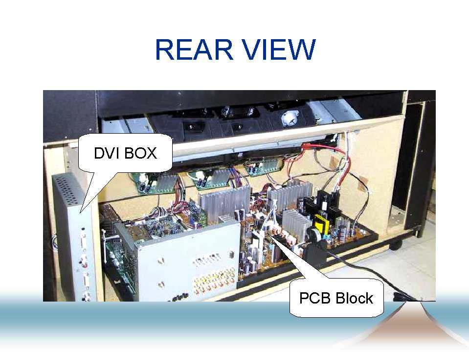
15
16 Copy Protect Detection Switch DVI Input 5 DVI Input 6 Caution: Switch must be closed for set to operate
17 DIGITAL INPUT Copy Protection The DVI module on this model utilizes DIGITAL INPUT COPY PROTECTION (DVI Ver1.0 with HDCP). The High Band Digital Content Protection System will activate when it detects one of the actions below has occurred. 1. If you turn on the power with the rear cover removed. 2. If you remove the cover while the set is on. 3. If you turn on the power with the lead wire cable disconnected to the DVI Assy. 4. If you turn on the power with the DVI Shield Case removed. When the protection function activates, main power SW is the state of ON, and standby LED (red) flashes. (repeat flashing :250ms on and 250ms off) When in protection mode, the set will not operate until protection mode has been released. Release method is as follows 1. Press the "RETURN" key on the front panel more than five seconds, or until the standby LED lights constanty. 2. Press the "POWER" key "RETURN" key "INPUT/SET" key in order within five seconds after standby LED lighted. 3. Press the "POWER" key, and turn on the product. 4. If you were not able to press the keys within five seconds in step 2 operation or mistook key operation, repeat steps 1 and 2. As the set has entered the protection mode again. 5. When confirming a problem with the product, enter the test mode temporarily so that the protection function does not activate again. Press the FACTORY key on the Front Panel twice, and enter the 2nd FACTORY mode. Press "48" key with the remote control unit, and enter the TEST mode. (display "TEST MODE" on the screen, and it should release the protect mode.) 6. After work completion, return the product to the original state. Enter the 2nd FACTORY mode, and release the test mode by pressing the "47" key. Flashing of The Power LED 1. Specification of red LED Standby lighting After having shifted from power management operation to normal standby (operation released the power management by turning the power off), continue lighting after flashing three times: Repeat 500ms off and 500ms on three times, and continue lighting. During copy protection operation Flashing: Repeat 250ms on and 250ms off. Relay welding Repeat three times flashing and once stop: Repeat 100ms on,100ms off,100ms on,100ms off,100ms on,100ms off and 1S off. 2. Specification of green LED Power on lighting During power-saving mode operation (power management) Flashing: Repeat 2s on and 2s off. About power management: When input signal disappears only at INPUT 5 or 6, it enters the power-saving mode.
18 SH MH SV Y Cb/Pb Cb/Pb Cr/Pr YVM CM 3D Y/C SEPA 4M DRAM Y Cr/Pr DVI IC2803 TA1340F IC2806 TA1340F IC2804 M52055FP IC2805 M52055FP IC1905 M62399FP MAIN UCOM IC1906 PD5815C8 IC3906 CXA2171Q IC3901 CXA2171Q IC LC32A(I)P ANT A ANT B SCL1,SDA1, AFT1 FE1 FE2 S.DET SCL1 SDA1 S.DET INPUT 1 INPUT 2 INPUT 3 INPUT F TV1 TV2 INPUT 1 INPUT 2 INPUT 3 INPUT 5 2LY 2LC IC2503 UPD64083GF-3BA IC2701 TC90A45F SCL2 SDA2 HBLK VBLK MCCY OSD OSDBLK OSDHALF SCL2 SDA2 MONITOR OUT SCCY / YCbCr MATRIX INPUT SELECT INPUT SELECT / YCbCr MATRIX SYNC SEP. SYNC SEP. SY SCB SCR MY MCB MCR SCL3 SDA3 V Y C S.DET AV SW 7 INPUT 3 OUTPUT V Y C S.DET V Y C S.DET V Y C S.DET IC2201 CXA2069Q SCCY EEPROM RS-232C 232C DRIVER RXD0 TXD0 RxD TxD RTS IC1801 SP3232ECY DAC IC SCL2 SDA2 DVIH DVIV MH MV SH SV MH MV SH SV HS VS SYNC SEP. COLOR DEMOD. 6dB AMP MCCY 3DY 3DC FIL TER SUB N/HSW MAIN N/HSW DSUB DSUBH DSUBV DSUB DVI DSUB/DVISW IC3907 M52055FP SCL1 SDA1 SCL1 SDA1 SCL1 SDA1 SCL1 SDA1 SCL2 SDA2 ESCL ESDA 2LINE Y/C SEP HS1 HS2 SCL1,SDA1,AFT2 ANTSW SCL3 SDA3 DVI DAC IC IC6016 CXA1875AN INPUT 6 RECEIVER RECEIVER SELECTOR SY SCB SCR MY MCB MCR MY MCB MCR SY SCB SCR SYNC SEP. COLOR DEMOD. 6dB AMP FIL TER
19 IC2807 TA74ACT04 INVERTER IC4306 M52055FP MH MV MY MCB MCR SY SCB SCR SV SH SCL2 SDA2 31K/33K PURE STDSW PROGRESSIVE UNIT AXY1061 AD AD TY TCB TCR DY DCB DCR IC4305 M52055FP COMP FULL IC4301 YCBCR AN5395FBP CP SHARP- GEN. NESS DCLP SCP SHARP- NESS DETAIL SHARP SW SPASS YCBCR DY MMUTE MMUTE SMUTE SMUTE APL DET 31KSW PGAIN PBRT I2C INTERFACE PLL PLL IC4601 M52055FP APL IP CONVERTER TWIN PICTURE HBLK1 GEN. BLACK LEVEL COMPENSATION PURE SDRAM KMASK APL UCOM RESIZE KMASK MASK GEN. LTI CTI VM COMP FULL DA 3DNR IPHBLK IC4608 CXA2180Q V ABL MATRIX IC4610 TC74HC126AF DVS SCL2 SDA2 DHS DY DCB DCR VM H MIX SVM IC4606 CXA2153S DHS HS IC4610 TC74HC126AF DVS VS DRIVE SYNC PROCESS AFC R G B HBLK 1 COMPENSATION ABL R SCL2 SDA2 HPIN HBLK HDRV VDRV± VBLK V MUTE ABL ACL G LIN B WHITE ENCODER HBLK 1 OSD SW OSD CRT AMP SCREEN FOCUS PACK FOCUS D.F HOUT DYNAMIC HIGH FOCUS VOLTAGE H.V. CR OUT BLOCK DF F.B. +B ANODE PD H.V. CPURST HVRST CONTROL ABL H.DEF DRV HDRV H.BLK H.DEF GEN. OUT FP +B P.D. H.DEF CONTROL CUTOFF OSDBLK VDRV ± PRE. AMP HPIN PD AMP V.DEF ANODE HSIZE P.D. OSD CV IC4602 TC74HC4053AF OSDBLK OSD/CV CVBLK OSDBLK SCL2 SDA2 CBUSY WP CRESET HS VS IC1204 CM0022AF HBLK DIGITAL CONVERGENCE PLL VBLK L P F IC1205 CD0031AM 6ch DAC IC L P F IC401, IC402 STK AMP MUTE CV CVBLK EEP ROM IC LC64(I)P CMUTE
20 SH MH SV Y Cb/Pb Cb/Pb Cr/Pr YVM CM 3D Y/C SEPA 4M DRAM Y Cr/Pr DVI IC2803 TA1340F IC2806 TA1340F IC2804 M52055FP IC2805 M52055FP IC1905 M62399FP MAIN UCOM IC1906 PD5815C8 IC3906 CXA2171Q IC3901 CXA2171Q IC LC32A(I)P ANT A ANT B SCL1,SDA1, AFT1 FE1 FE2 S.DET SCL1 SDA1 S.DET INPUT 1 INPUT 2 INPUT 3 INPUT F TV1 TV2 INPUT 1 INPUT 2 INPUT 3 INPUT 5 2LY 2LC IC2503 UPD64083GF-3BA IC2701 TC90A45F SCL2 SDA2 HBLK VBLK MCCY OSD OSDBLK OSDHALF SCL2 SDA2 MONITOR OUT SCCY / YCbCr MATRIX INPUT SELECT INPUT SELECT / YCbCr MATRIX SYNC SEP. SYNC SEP. SY SCB SCR MY MCB MCR SCL3 SDA3 V Y C S.DET AV SW 7 INPUT 3 OUTPUT V Y C S.DET V Y C S.DET V Y C S.DET IC2201 CXA2069Q SCCY EEPROM RS-232C 232C DRIVER RXD0 TXD0 RxD TxD RTS IC1801 SP3232ECY DAC IC SCL2 SDA2 DVIH DVIV MH MV SH SV MH MV SH SV HS VS SYNC SEP. COLOR DEMOD. 6dB AMP MCCY 3DY 3DC FIL TER SUB N/HSW MAIN N/HSW DSUB DSUBH DSUBV DSUB DVI DSUB/DVISW IC3907 M52055FP SCL1 SDA1 SCL1 SDA1 SCL1 SDA1 SCL2 SDA2 ESCL ESDA 2LINE Y/C SEP HS1 SCL1,SDA1,AFT2 ANTSW SCL3 SDA3 DVI DAC IC IC6016 CXA1875AN INPUT 6 RECEIVER RECEIVER SELECTOR SY SCB SCR MY MCB MCR MY MCB MCR SY SCB SCR SYNC SEP. COLOR DEMOD. 6dB AMP FIL TER
21 IC2807 TA74ACT04 INVERTER IC4306 M52055FP MH MV MY MCB MCR SY SCB SCR SV SH SCL2 SDA2 31K/33K PURE STDSW PROGRESSIVE UNIT AXY1061 AD AD TY TCB TCR DY DCB DCR IC4305 M52055FP COMP FULL IC4301 YCBCR AN5395FBP CP SHARP- GEN. NESS DCLP SCP SHARP- NESS DETAIL SHARP SW SPASS YCBCR DY MMUTE MMUTE SMUTE SMUTE APL DET 31KSW PGAIN PBRT I2C INTERFACE PLL PLL IC4601 M52055FP APL IP CONVERTER TWIN PICTURE HBLK1 GEN. BLACK LEVEL COMPENSATION PURE SDRAM KMASK APL UCOM RESIZE KMASK MASK GEN. LTI CTI VM COMP FULL DA 3DNR IPHBLK IC4608 CXA2180Q V ABL MATRIX IC4610 TC74HC126AF DVS SCL2 SDA2 DHS DY DCB DCR VM H MIX SVM IC4606 CXA2153S DHS HS IC4610 TC74HC126AF DVS VS DRIVE SYNC PROCESS AFC R G B HBLK 1 COMPENSATION ABL R SCL2 SDA2 HPIN HBLK HDRV VDRV± VBLK V MUTE ABL ACL G LIN B WHITE ENCODER HBLK 1 OSD SW OSD CRT AMP SCREEN FOCUS PACK FOCUS D.F HOUT DYNAMIC HIGH FOCUS VOLTAGE H.V. CR OUT BLOCK DF F.B. +B ANODE PD H.V. CPURST HVRST CONTROL ABL H.DEF DRV HDRV H.BLK H.DEF GEN. OUT FP +B P.D. H.DEF CONTROL CUTOFF OSDBLK VDRV ± PRE. AMP HPIN PD AMP V.DEF ANODE HSIZE P.D. OSD CV IC4602 TC74HC4053AF OSDBLK OSD/CV CVBLK OSDBLK SCL2 SDA2 CBUSY WP CRESET HS VS IC1204 CM0022AF HBLK DIGITAL CONVERGENCE PLL VBLK L P F IC1205 CD0031AM 6ch DAC IC L P F IC401, IC402 STK AMP MUTE CV CVBLK EEP ROM IC LC64(I)P CMUTE
22 SH MH SV Y Cb/Pb Cb/Pb Cr/Pr YVM CM 3D Y/C SEPA 4M DRAM Y Cr/Pr DVI IC2803 TA1340F IC2806 TA1340F IC2804 M52055FP IC2805 M52055FP IC1905 M62399FP MAIN UCOM IC1906 PD5815C8 IC3906 CXA2171Q IC3901 CXA2171Q IC LC32A(I)P ANT A ANT B SCL1,SDA1, AFT1 FE1 FE2 S.DET SCL1 SDA1 S.DET INPUT 1 INPUT 2 INPUT 3 INPUT F TV1 TV2 INPUT 1 INPUT 2 INPUT 3 INPUT 5 2LY 2LC IC2503 UPD64083GF-3BA IC2701 TC90A45F SCL2 SDA2 HBLK VBLK MCCY OSD OSDBLK OSDHALF SCL2 SDA2 MONITOR OUT SCCY / YCbCr MATRIX INPUT SELECT INPUT SELECT / YCbCr MATRIX SYNC SEP. SYNC SEP. SY SCB SCR MY MCB MCR SCL3 SDA3 V Y C S.DET AV SW 7 INPUT 3 OUTPUT V Y C S.DET V Y C S.DET V Y C S.DET IC2201 CXA2069Q SCCY EEPROM RS-232C 232C DRIVER RXD0 TXD0 RxD TxD RTS IC1801 SP3232ECY DAC IC SCL2 SDA2 DVIH DVIV MH MV SH SV MH MV SH SV HS VS SYNC SEP. COLOR DEMOD. 6dB AMP MCCY 3DY 3DC FIL TER SUB N/HSW MAIN N/HSW DSUB DSUBH DSUBV DSUB DVI DSUB/DVISW IC3907 M52055FP SCL1 SDA1 SCL1 SDA1 SCL1 SDA1 SCL2 SDA2 ESCL ESDA 2LINE Y/C SEP HS1 HS2 SCL1,SDA1,AFT2 ANTSW SCL3 SDA3 DVI DAC IC IC6016 CXA1875AN INPUT 6 RECEIVER RECEIVER SELECTOR SY SCB SCR MY MCB MCR MY MCB MCR SY SCB SCR SYNC SEP. COLOR DEMOD. 6dB AMP FIL TER
23 IC2807 TA74ACT04 INVERTER IC4306 M52055FP MH MV MY MCB MCR SY SCB SCR SV SH SCL2 SDA2 31K/33K PURE STDSW PROGRESSIVE UNIT AXY1061 AD AD TY TCB TCR DY DCB DCR IC4305 M52055FP COMP FULL IC4301 YCBCR AN5395FBP CP SHARP- GEN. NESS DCLP SCP SHARP- NESS DETAIL SHARP SW SPASS YCBCR DY MMUTE MMUTE SMUTE SMUTE APL DET 31KSW PGAIN PBRT I2C INTERFACE PLL PLL IC4601 M52055FP APL IP CONVERTER TWIN PICTURE HBLK1 GEN. BLACK LEVEL COMPENSATION PURE SDRAM KMASK APL UCOM RESIZE KMASK MASK GEN. LTI CTI VM COMP FULL DA 3DNR IPHBLK IC4608 CXA2180Q V ABL MATRIX IC4610 TC74HC126AF DVS SCL2 SDA2 DHS DY DCB DCR VM H MIX SVM IC4606 CXA2153S DHS HS IC4610 TC74HC126AF DVS VS DRIVE SYNC PROCESS AFC R G B HBLK 1 COMPENSATION ABL R SCL2 SDA2 HPIN HBLK HDRV VDRV± VBLK V MUTE ABL ACL G LIN B WHITE ENCODER HBLK 1 OSD SW OSD CRT AMP SCREEN FOCUS PACK FOCUS D.F HOUT DYNAMIC HIGH FOCUS VOLTAGE H.V. CR OUT BLOCK DF F.B. +B ANODE PD H.V. CPURST HVRST CONTROL ABL H.DEF DRV HDRV H.BLK H.DEF GEN. OUT FP +B P.D. H.DEF CONTROL CUTOFF OSDBLK VDRV ± PRE. AMP HPIN PD AMP V.DEF ANODE HSIZE P.D. OSD CV IC4602 TC74HC4053AF OSDBLK OSD/CV CVBLK OSDBLK SCL2 SDA2 CBUSY WP CRESET HS VS IC1204 CM0022AF HBLK DIGITAL CONVERGENCE PLL VBLK L P F IC1205 CD0031AM 6ch DAC IC L P F IC401, IC402 STK AMP MUTE CV CVBLK EEP ROM IC LC64(I)P CMUTE
24 ANT A FE2 AV SW IC2201 CXA2069Q ANT B FE1 SCL1,SDA1,AFT1 TV1 L,R -6dB ATT ATT +6dB AMP INPUT 1 INPUT 2 INPUT 3 INPUT F L R L R L R L R INPUT1 L,R INPUT2 L,R INPUT3 L,R INPUTF L,R INPUT5,6 DVI L,R ATT ATT ATT ATT ATT MONITOR/TV OUT AMP INPUT 5 INPUT 6 L R AUDIO OUT VAR/FIX MUTE VAR/FIX SW FIX L,R AUDIO OUT L R VAR/FIX MUTE IC2203 MC14066BF VAR L,R CENTER IN MONITOR/ TV OUT L R MONITOR MUTE MON/TV MUTE
25 L,R CENTER L,R/CENTER IC2202 MC14066BF CENTER SW ATT IC5502 BH3865S AGC FRONT SURROUND PRE AMP SCL2 SDA2 TONE CONTROL BASS BOOST AMUTE2 VOL.CONTROL AUDIO MUTE IC5501 NJM4558MD AMP IC5503 IC5504 NJM4558MD DC DETECTION TRAP ATT AUDIO MUTE AMP PHASE SECURITY AMUTE IC1101 LA4282 POWER AMP SPEAKER CMUTE AMUTE2
26 Tuner, Video and S Input Block Explanation (See Pages 17 and 18) Main Picture (Tuner or Composite) Input switch (IC2201) receives signals from the tuner, inputs 1 ~ 3 and the front input (input F). Signals from the tuner or composite signals from inputs 1,2,3 or F enter IC2201 and the user selected output for the main picture goes to IC2503. IC2503 is a 3D Y/C separator for the main picture composite signals. After the composite signals have been changed to 3D-Y/C signals they enter IC2803 and the color demodulator inside this IC changes the signals to Y/CB/CR. IC2803 also separates the horizontal and vertical sync. All signals at this point are sent onto the progressive unit for I/P conversion. All signals entering the progressive unit are converted to 480P at 31K or 1080I at 33K (user selectable). Signals entering the progressive unit are converted to digital and resized for the user selected screen mode and scan mode. The output signals from the progressive unit are converted back to analog and the Y/CB/CR signals pass through switch IC4305 and go into the sharpness and detail correction IC (IC4301) or bypass IC4301 through switch IC4306 and enter IC4608. All picture, color correction and sync processing is done inside IC4608. The output processed signal from IC4608 is sent to the CRT drive PCB s. Main Picture ( S ) Inputs from the S connectors (inputs 1,2,3 and F) are user selected by IC2201 and outputted to IC2503 as Y and C signals. Since these signals are already separated IC2503 simply passes the signals through onto IC2803. From this point the signal path is exactly the same as (Tuner or Composite). Sub Picture (Tuner, Composite or S ) The sub picture path is used for the twin picture function and the multi picture tuner scan feature. Any signal input into IC2201 can be used for the sub picture output. The user selected sub picture output from IC2201 goes to IC2701 for Y/C separation if the signal is Tuner or Composite. If the signal is of the S type it simply is passed through IC2201 and enters IC2806 for color demodulation and sync separation. The outputted Y/CB/CR and sync signals are then sent to the progressive unit for twin picture or multi picture processing.
27 Component Input Block Explanation (See Pages 19 and 20) Main Picture (Input 1 or 2 Component 480I 15K, 480P 31K and 720P 45K) IC3901 is used as the input 1 and 2 main picture selector and if the input is 480I, 480P or 720P the user selected signals pass through IC3901 and enter IC2803. The Y/CB/CR signals bypass the color demodulator and go directly to the progressive unit. The sync signals are separated by IC3901 and pass through IC2803 and onto the progressive unit for processing. 15K sync signals entering the progressive unit are doubled, 31K pass though and 45K signals are converted to 31K and outputted to IC4608 for final processing. Sub Picture (Input 1 or 2 Component 480I or 480P) Component inputs 1 or 2 can be used for the sub picture (twin picture) function as long as the signals are 480I or 480P and full mode has not been selected. Note: 720P cannot be used as a sub picture source. 720P defaults to full screen mode only. IC3906 is the input user selector switch for the sub picture from component inputs 1 or 2. The selected Y/CB/CR signals along with the separated sync signals go to IC2806. The Y/CB/CR and separate sync signals pass through IC2806 and go onto the progressive unit for twin picture and sync processing. Main Picture (1080I 33K and 480P Full-Mode) IC3901 (the main picture component output selector) user selects input 1 or 2 and outputs the Y/CB/CR signals in 1080I or 480P full-mode format and sends the signals to IC4305 (the full component switch). From IC4305 the signal directly enters IC4606 for picture, color and processing. The separated 31k or 33K sync signals from IC3901 also go directly to IC4606 after passing through switch IC4610 for sync processing. 480P full-mode requires no size conversion from the I/P converter inside the progressive unit.
28 DVI & Input Block Explanation (See Pages 21 and 22) Main Picture (Input 5 or 6 DVI 480P) From the selector IC inside the DVI module the user selects input 5 or 6 and that DVI- signal and sync is sent to IC3901 to be converted to Y/CB/CR and separate H and V sync. The outputs of IC3901 go directly to IC2803 but only pass through this IC as they are already component signals and the sync has been separated. From IC2803 the signals are sent to the progressive unit for size and sync processing and onto IC4608 for final picture, color correction and sync processing. Sub Picture (Input 5 or 6 DVI 480P) Only one DVI input can be used to produce a sub picture (split screen effect) along with one of the other inputs. If the user selects input 5 or 6, the selector IC inside the DVI module sends that output to IC3906 for to Y/CB/CR converting along with sync separating of the H and V sync signals. At this point all signals pass through IC2806 and onto the progressive unit for twin picture and sync processing. Main Picture (1080I 33k and 480P 31K Full-Mode) IC3901 (the main picture DVI output selector) selects input 5 or 6 and converts the signals into Y/CB/CR signals in 1080I or 480P full-mode format and sends the signals to IC4305 (the full component switch). From IC4305 the signal directly enters IC4606 for picture, color and processing. The separated 31k or 33K sync signals from IC3901 also go directly to IC4606 after passing through switch IC4610 for sync processing. 480P full-mode requires no size conversion from the I/P converter inside the progressive unit. Main Picture (DVI Pure Digital Mode 1080I) If the user selects Pure Digital mode than the path for input 5 or 6 will go through IC3907 (DVI/ selector IC) and switch IC4601 to IC4606 and enter the matrix area for final processing before being sent onto the CRT drives. The sync signal is separated by IC3901 and passes through switch IC4610 and finally processed by IC4606. Main Picture 1080I (DSUB Connector 3) The signal path for the (DSUB) input 3 connector is exactly the same as DVI Pure Digital Mode. As you can see in the block diagram cannot be used as a sub picture or in any other scan or screen mode other than 1080I full.
29 Audio Input/Output Block Explanation (See Pages 23 and 24) Audio Input All inputted audio signals connect directly to IC2201 the main audio and video switch located on the Video UCOM PCB. When the user selects an audio and video source the main UCOM (IC1906) sends a serial command to IC2201 for selecting the proper input source. Note: The only input that does not go through IC2201 is the Center Channel Input. After proper input selection by IC2201 the right and left audio signals go to switch IC2202 the (left/right & center) switch. If the user had selected in the menu to use the set a center channel for all inputs this switch would move to the lower position. If the switch is in the L,R position the signals pass onto the preamp IC5502 located on the power supply PCB. The preamp IC provides input gain control, tone, bass boost, front surround and operates as an electronic volume control. From the preamp the signals pass onto the power amp IC1101 and onto the speakers. DC detection is provided prior to the speaker output to prevent damage to the speakers. This detection will cause the set to shut down. See page 60 and 62 for details. Audio Output The audio output jacks on this set can be used as a Fixed or Variable type. When used as a Fixed type the L,R audio signals from IC2201 simply pass through the switch IC2203 and the muting circuit than onto the RCA type jacks located on the back. If the menu has been set to make the output Variable the signals pass through the preamp and electronic volume control prior to entering switch IC2203. Monitor/TV Output If the system mode is set to OFF (the default setting) this output operates the same as the normal audio output jacks in fixed mode. If the user selects (System Mode On) from the menu this output sends the signal from the tuner only.


30 A TUNER ASSY B SIGNAL ASSY FE2 FE1 3D Y/C SEP Block 2L Y/C SEP Block AV I/O Block COMPONENT SW Block I DVI SERVICE ASSY SR Block A TUNER ASSY ANT A ANT B INPUT 1 V Y S.DET C INPUT 2 V Y S.DET C INPUT 3 V Y S.DET C INPUT F V Y S.DET C MONITOR OUT SCL1,SDA1,AFT2 FE2 FE1 SCL1,SDA1, ANTSW AFT1 TV1 S.DET S.DET AV I/O Block AV SW 7 INPUT 3 OUTPUT IC2201 CXA2069Q SCL1 SDA1 TV2 HS2 YVM CM HS1 4M DRAM 3D Y/C SEPA 3D Y/C SEP Block 2LINE SV Y/C SEP IC2701 TC90A45F 2L Y/C SEP Block B SIGNAL ASSY SCL1 SDA1 IC2503 UPD64083GF-3BA 2LY 2LC 3DY 3DC INPUT 5 INPUT 6 I INPUT 1 Y Cb/Pb Cr/Pr INPUT 2 Y INPUT 3 Cb/Pb Cr/Pr RECEIVER SELECTOR RECEIVER RS-232C RxD TxD RTS IC1801 SP3232ECY 232 DRIVER COMPONENT SW Block SCL3 SDA3 DSUBH DSUBV DSUB DVI DAC IC IC6016 CXA1875AN DVI DVI SERVICE ASSY SR Block IC3901 CXA2171Q DVIH DVIV INPUT SELECT INPUT SELECT SCL1 SDA1 SYNC SEP. / YCbCr MATRIX SCL1 SDA1 SYNC SEP. / YCbCr MATRIX IC3906 CXA2171Q DSUB RXD0 TXD0 MH MV MYMCBMCR SH SV SYSCBSCR DSUB/DVISW DVI IC3907 M52055FP
P SV 6dB AMP MCCY SY SCB SCR DY DCB DCR MAIN UCOM IC1906 PD5815AB VMUTE KMASK TY TCB TCR SUB N/HSW SCCY EEPROM CRT AMP DHS DY DCB DCR SH FIL TER SCC Y UCOM Block SYSCBSCR SMUTE DVS")

31 Circuit location By PCB J VIDEO UCOM SERVICE ASSY K R CRT DRIVE ASSY SHARPNESS Block VIDEO Block AFC Block AUDIO PRE AMP Block UCOM Block VIDEO UCOM SERVICE ASSY MY MCB FIL MCR TER IC2805 M52055FP IC LC32A(I)P SV 6dB AMP MCCY SY SCB SCR DY DCB DCR MAIN UCOM IC1906 PD5815AB VMUTE KMASK TY TCB TCR SUB N/HSW SCCY EEPROM CRT AMP DHS DY DCB DCR SH FIL TER SCC Y UCOM Block SYSCBSCR SMUTE DVS PROGRESSIVE UNIT AXY1061 SCL1 SDA1 SCL2 SDA2 HBLK VBLK HBLK 1 Y CB CR IC4301 KMASK AN5395FBP CP HBLK1 MASK SHARPGEN. GEN. GEN. DCLP NESS IPHBLK SCP SHARPNESS DETAIL VIDEO Block B IC4601 APL M52055FP G SCL2 SDA2 HBLK VBLK ENCODER HBLK 1 R G LIN B WHITE OSDBLK APL DET RXD0 TXD0 R YCBCR DY IC4606 CXA2153S IC4608 CXA2180Q ABL ABL ACL PURE OSD OSD OSDBLK IC4305 M52055FP CUTOFF SYNC SEP. COLOR DEMOD. MAIN N/HSW OSD SW IC2806 TA1340F MYMCBMCR MMUTE 6dB AMP MC CY MV R,G,B CRT DRIVE ASSYS SH ABL COLOR DEMOD. K L M MH INVERTER COMPENSATION 2LY 2LC SY SCB SCR MH TA74ACT04 IC4306 M52055FP SH SV IC2804 M52055FP SYNC SEP. MH MV 3DY 3DC MY MCB MCR IC2807 IC2803 TA1340F AFC Block SHARPNESS Block J M B CRT DRIVE ASSY L G CRT DRIVE ASSY 30.

32 N DEFLECTION SERVICE ASSY POWER SUPPLY 2 Block PRIMARY 2 Block V DEF Block SECONDARY 2 Block H DEF Block HIGH VOLTAGE Block DYNAMIC FOCUS Block J901 LIVE 1 NEUTRAL 2 PRIMARY 2 Block D901 SW REGULATOR CONTROL IC901 AN8029 T901 SECONDARY 2 Block FU1001 D1007 FU1002 D1009 FU1003 D1010 IC1001 D1016 V+21V V-20V HT+ V+120V V DEF Block VDRV ± IC801 IC802 M5220P LA78045 PRE AMP V AMP VOUT HOUT HIGH VOLTAGE Block HIGH VOLTAGE OUTPUT T601 ANODE FOCUS HDRV Q512,Q513 H. DEF DRIVE Q511 H. DEF OUT PD CPURST ABL F.B +B H.V. CONTROL HPIN H. DEF CONTROL IC502 NJM4558DXP Q510,Q508 HVRST


33 P POWER SUPPLY ASSY POWER SUPPLY 1 Block VELOCITY MODULATION Block STANDBY Block PRIMARY 1 Block CONVERGENCE AMP Block AUDIO POWER AMP Block SECONDARY 1 Block DIGITAL CONVERGENCE Block O DIGITAL CONV. ASSY PRIMARY 1 Block S5291 POWER SECONDARY 1 Block P POWER SUPPLY ASSY 1 2 FU201 RY202 D102 T101 D103 V+5STB VM VM Block SVM (VM AMP) Block VM COIL CY RY201 D201 SW REG. CONTROL IC201 AN8029 T201 FU301 FU302 FU303 FU304 D301 D303 D305 D307 D313 V+4V V+6V V+10V V+13V V+30V HBLK VBLK CONVERGENCE AMP Block DIGITAL CONVERGENCE IC1204 CM0022AF 6 ch DAC IC205 CD0031AM O DIGITAL CONV. ASSY IC401, IC402 STK CONVER AMP


34 7.1.2 DISASSEMBLY About detect switch This unit adopts the "Rear Cover opened! detection" system. Outline and caution This unit uses contents protection by HDCP for copyright protection. Never turn on the power to this unit with the rear cover removed without holding the detect switch closed. Note: You can remove the Screen without removing the Frame Cover and AR Panel. 1 Frame Cover and AR Panel Disassembly : Assembly : Remove the Frame Cover V Assy L and R Detect switch does not detect at power supply OFF or the remote control unit wait state. Please close this detect switch with tape before turning on the power. Frame Cover V Assy L Frame Cover V Assy R Cloth Rear View Flat-blade Screw Driver Detect Switch (S2) 2 Remove the Frame Cover H Flat-blade Screw Driver Cloth When detect switch has Activated Main unit key (Remote control unit key is impossible.) RETURN Hold for more than five seconds POWER RETURN Press it within five seconds. INPUT Flat-blade Screw Driver Cloth Start with the service factory mode. Frame Cover H
35 3 4 Remove five screws Remove four screws Remove the AR Panel Caution : As oil from the hands is easily attached to, but difficult to remove from the AR panel, be sure to wear gloves when you handle the panel. If stains are attached to the panel, wipe them off with a piece of clean cloth moistened with water. If stains persist, use undiluted alcohol AR Panel Remove the Panel Frame H Remove the Panel Frame V Panel Frame H Panel Frame V 5 Panel Frame V 8 9 Remove five screws Remove the Panel Frame H 6 6 Panel Frame H 9 8 5
36 Screen Note: You can remove the Screen without removing the Frame Cover and AR Panel. 1 Remove eight screws 2 Remove the Screen Frame Assy Screen Frame Assy 8 Remove the Screen Screen Holder TOP Lenticular Sheet Fresnel 3 Remove four screws to remove the Screen Side Fitting 4 Remove a screw 5 Remove a screw (Only unscrew in the lens adjustment.) 6 Remove the Upper Cabinet Metal 7 Remove four screws to remove the Upper Cabinet Metal (Only unscrew in the lens adjustment.) 4 5 Upper Cabinet Metal 7 2 Upper Cabinet Metal 8 Slide the screen to right (when perform the lens adjustment) 8 6 Screen Side Fitting Screen Side Fitting Notes: To assemble the screen, perform the above procedures in reverse order. After assembling it, put positions together so that right and left become equal.

37 Disconnect the Anode Cable WARNING: Before you disconnect the anode cable, turn off the power, unplug the AC plug and let the unit discharge for more than 1 minute. MEASURING METHOD Disconnect the FBT anode cable as shown below. Measure at the point where the cable enters the FBT. Caution : Take extra precaution when measuring the voltage. High voltages are also present in surrounding circuit boards. (CRT assy, POWER SUPPLY assy) SERVICEMAN WARNING Before removing the anode cable, turn off the power, unplug the AC plug and let the unit discharge for more than 1 minut. Anode Cable Pull straight up Cover Pull straight up Note : FBT When reconnecting the cable, proceed in the reverse order. After reconnecting, tug on the cable to check that it is secure. Rear View FBT DEFLECTION SERVICE Assy
38 ADJUSTMENT INTRODUCTION IMPORTANT When replacement of the following assemblies are required during repairs, be sure to replace the EEPROMs in order to retain the adjustment data of the unit and to facilitate adjustment after the replacement of the assemblies. PC Board EEPROM Main Contents of Memory VIDEO UCOM SERVICE Assy IC1903 [24LC32(I)P] Adjustment data, such as W/B and color data, Convergence offset data in FACTORY mode, User data set on the MENU DIGITAL CONV. Assy IC1203 [24LC64(I)P] Convergence adjustment data Notes: Even if the EEPROMs are replaced, adjustment may be necessary, depending on the part or assembly to be replaced. Even if the EEPROMs are replaced, if the EEPROMs are damaged or if their data have been changed from the adjustment data, the status before the failure will not be restored. Check the status of the unit after replacement of the EEPROMs, and readjust if necessary. JIGS AND MEASURING INSTRUMENTS Remote control unit AXD1468 Screwdriver Adjustment screwdriver Color bar generator D. DC Voltmeter DVD / LD Player Monoscope Dual-trace oscilloscope HD Signal generator Soldering iron
39 ADJUSTMENT LOCATION AND ITEMS Assembly Adjustment Location I DVI SERVICE Assy VIDEO UCOM J SERVICE Assy DIGITAL CONV. O Assy DEFLECTION N SERVICE Assy MEASURING METHOD Disconnect the FBT anode cable as shown below. Measure at the point where the cable enters the FBT. Caution : Take extra precaution when measuring the voltage. High voltage are also present in surrounding circuit boards. (CRT assy, POWER SUPPLY assy) SERVICEMAN WARNING Before removing the anode cable, turn off the power, unplug the AC plug and let the unit discharge for more than 1 minut. Anode Cable TUNER A Assy SIGNAL B Assy Pull straight up POWER SUPPLY P Assy Cover Rear View Pull straight up FBT Note : When reconnecting the cable, proceed in the reverse order. After reconnecting, tug on the cable to check that it is secure. Lens assy (For Red) Lens assy (For Green) Lens assy (For Blue) B G R Focus VR Focus VR (VR1) Rear View CRT SERVICE Assy B CRT SERVICE Assy G CRT SERVICE Assy R Front View Deflection Yoke Deflection Yoke (B) B CRT DRIVE Assy BK GK RK G CRT DRIVE Assy R CRT DRIVE Assy Centering magnet (Turn in either direction untill cross signal becomes white.) Deflection Yoke (G) Deflection Yoke (R) Adjustment Items 1 Brightness Adjustment 2 Deflection Yoke Adjustment 3 Focus Adjustment 4 Screen Size Adjustment 5 Convergence Adjustment 6 White Balance Adjustment 7 Panel Adjustmen for 480i 8 Panel Adjustment for 480P
40 Assembly Adjustment Location Guide If POWER SUPPLY ASSY is repaired or replaced 5 Convergence Adjustment If DEFLECTION SERVICE ASSY is repaired or replaced Brightness Adjustment ( 2) Focus Adjustment (VR1: FOCUS VR) ( 2) Screen Size Adjustment ( 2) Convergence Adjustment ( 2) White Balance Adjustment ( 2) If R, G or B CRT DRIVE ASSY is repaired or replaced 1 6 Brightness Adjustment ( 1) White Balance Adjustment (Composite STD : 1, Others : 2) If DIGITAL CONV. ASSY is repaired or replaced Focus Adjustment ( 2) Screen Size Adjustment ( 2) Convergence Adjustment ( 2) If VIDEO UCOM SERVICE ASSY is repaired or replaced Brightness Adjustment ( 2) White Balance Adjustment (Composite STD : 1, Others : 2) Panel Adjustment for 480i ( 1) Panel Adjustment for 480P ( 1) If SIGNAL ASSY is repaired or replaced No adjustment is required If DVI SERVICE ASSY is repaired or replaced No adjustment is required If CRT ASSY (R, G or B) is repaired or replaced Brightness Adjustment ( 1) Deflection Yoke Adjustment ( 1) Focus Adjustment (Lens : 2, VR1 Focus VR : 1) Convergence Adjustment ( 2) White Balance Adjustment (Composite STD : 1, Others : 2) If LENS ASSY (R, G or B) is repaired or replaced 3 5 Focus Adjustment (Lens : 1, VR1 Focus VR : 2) Convergence Adjustment ( 2) If MIRROR and SCREEN is repaired or replaced 5 Convergence Adjustment ( 2) If OTHER ASSY is repaired or replaced No adjustment is required Note : *1: Readjustment necessary *2: Turn on the power and confirm the screen. When adjustment deviates, readjusted if necessary. When the EEPROMs are replaced, check the status of the unit. If any IC of the EEPROM is damaged, readjustment of all the items is necessary. The necessary adjustment items differ, depending on the assembly or optical part replaced. Check and readjust the adjustment items corresponding to the replaced assembly or part, following adjustment procedures 1 to 8. Example: When the DIGITAL CONV. Assy is replaced, perform the following: 3. Focus check/adjustment 4. Screen size check/adjustment 5. Convergence check/adjustment
41 FACTORY ADJ MODE Factory Adjustment Mode Select 1st FACTORY ADJ Mode Start 1st FAC Selecting the mode for adjustment operations. Start adjusting Select 1st FACTORY ADJ mode, then adjust. Start TV Front panel Normal picture POWER " ON " INPUT1 position Press the switch with thin rod. 2nd FAC- TORY ADJ mode picture Cyclically 1st FAC- TORY ADJ mode picture The 2nd FACTORY ADJ mode is not used in the adjustment. To enter FACTORY mode, use the key(s) on the remote control unit or main unit. To release FACTORY mode, use the key(s) of the remote control unit or the main unit, or turn the power off. If the unit remains in FACTORY mode without any operation for 8 minutes, it will be automatically released. In FACTORY mode, data for the picture and audio qualities are standard, and the FLESH TONE setting is always off. When the unit enters FACTORY mode, settings such as audio muting, MENU, and SPLIT (two split-screens) are released. The Convergence data which user adjusted are within the FACTORY mode. Clear the convergence data by releasing the FACTORY mode after it is further within the MANUAL CONVER mode or OFFSET CONVER mode. When the unit exits FACTORY mode, the TV/CATV mode becomes AIR (settings of ANT and CH are those last stored in memory). CONVER. OSD (cross hatch) can be turned on and off cyclically by using the YELLOW key only during CONVER mode (MANUAL, AUTO, OFFSET adjustments). (Default: The cross hatch is on only in CONVER. mode.) 1 INPUT OFFSET mode (MUTING) RANGE CHECK mode (TV/SAT/DVD MENU) (SPLIT) SERVICE mode 6 Telop : White Telop : Red Telop : White (MUTING) (MUTING) (SPLIT) (SPLIT) 2 PICTURE OFFSET mode SIGNAL ADJ mode 5 PureCinema mode 7 Telop : White Telop : White Telop : White (MUTING) (MUTING) 3 COLOR TEMP (MUTING) CONVER ADJ mode 4 OFFSET mode Telop : White Telop : White
42 1 INPUT OFFSET Mode INPUT OFFSET MODE 1. STD 2. COMP (15kHz) 3. COMP (31kHz) 4. COMP (33kHz) 5. COMP (45kHz) 6. PURE 7. PURE (DVI) 8. TV Adjustment for service is only 1. STD, 4. COMP (33KHz) and 6.PURE. INPUT OFFSET Mode Key (s) on the Remote Control Unit 1 STD (DOWN) 4 COMP (33kHz) PinP CH+, SUB CH+ 6 PURE CH ENTER (MUTING) STD F1 COLOR 24 Telop : Blue 2 PICTURE OFFSET Mode 3 COLOR TEMP OFFSET Mode PICTURE OFFSET MODE 1. RTM 2. GAME 3. MODULE 4. - YCbCr: 33K 5. - YCbCr: 31K COLOR TEMP OFFSET MODE 1. NEWS 2. LIVE 3. FILM 4. B&W 5. FILM FOR RTM Do not perform the adjustment for service. Do not perform the adjustment for service. 4 CONVER ADJUST Mode CONVER ADJUST MODE 1. SIZE 2. OFFSET CONVER MODE1 3. OFFSET CONVER MODE2 4. OFFSET CONVER MODE3 5. FINE CONVER 6. AUTO CONVER 7. CONVER STATIC 8. DVI H.PHA ADJ CONVER ADJ Mode 1 SIZE ANT OFFSET CONVER 4 (DOT) MODE3 5 FINE CONVER SET Key (s) on the Remote Control Unit Adjustment for service is items of 1, 4 and 5. (MUTING) Mode changes cyclically as follows when uses the (DOT) key. OFFSET CONVER MODE1 OFFSET CONVER MODE2 ADJUST H SIZE F1 20 Telop : White OFFSET CONVER MODE3 For Adjustment of this item, screen mode has two modes as FULL and HD. Screen mode changes by the "SCREEN" key cyclically. FULL HD 5 SIGNAL ADJ Mode SIGNAL ADJ MODE I PANEL P PANEL 3. SIGNAL 4. TUNER TEST MODE 5. AUTO ACL 6. DVI LPF ADJ SIGNAL ADJ Mode Key (s) on the Remote Control Unit 1 480I PANEL CH RET 2 480P PANEL (RIGHT) 5 AUTO ACL PinP CH, SUB CH ADJUSTMENT 480I PANEL BRIGHT 10 Adjustment for service is items of 1, 2 and 5. (MUTING) Telop : Yellow 6 SERVICE Mode 7 PureCinema Mode SERVICE MODE 1. TIME SPACE FILTER 2. Y MOTION ADAPTATION 3. C MOTION ADAPTATION 4. AFC SYSTEM 5. IP SETTING 6. FREQ JUDGMENT ADJ PureCinema MODE COMPONENT ADJ S VIDEO ADJ COMPOSITE ADJ COMPONENT ADJ S VIDEO ADJ COMPOSITE ADJ Do not perform the adjustment for service. Do not perform the adjustment for service.
43 ADJUSTMENT 1 Brightness Adjustment Start 1st FAC Input signal : Black Burst (INPUT 1) Black burst (DOWN) STD CUT R b 0 CH b 0 4 STD OFFSET Telop: Blue Data value BRIGHT VOL 0 CH : CUT-R : CUT-G : CUT-B Cut off level (180V DC) GND CH1 (X) CH2 (Y) VOL or Cut off level (180V DC) GND CH1 (X) CH2 (Y) B CRT DRIVE ASSY VR5201 G CRT DRIVE ASSY TP-GK Oscilloscope B CRT DRIVE ASSY TP-BK Oscilloscope R CRT DRIVE ASSY Cut off level (180V DC) GND TP-RK CH1 (X) CH2 (Y) Oscilloscope R CRT DRIVE ASSY VR5101 When the DEFLECTION SERVICE Assy or VIDEO UCOM SERVICE Assy is replaced, check the following to confirm if the above adjustment is necessary: (1) Make a note of the data of CUT R, CUT G, CUT B, and BRIGHT. (1st FAC) ( DOWN) (2) Input "0" as parameters for (1) and check TP-RK, TP-GK and TP-BK of the CRT DRIVE assembly. If the levels are within 180 V ±5 V, the adjustment is not necessary. Input the noted data. If the levels are not within the above level, proceed with the above adjustment.

44 2 Deflection Yoke Adjustment 2-1 Deflection Yoke Lean Adjustment Start Input a stable signal (e.g. from an DVD / LD player or SG) to the INPUT 1 connector. MENU SETUP CONVERGENCE ADJUSTMENT FOR 480P ADJ MULTI-POINT The cross hatch disappears if there is no operation with the remote control unit for about 8 minutes. If the cross hatch disappears, repeat the above operation with the remote control unit or main unit key. CRT SERVICE Assy B CRT SERVICE Assy G CRT SERVICE Assy R Cross hatch Deflection yoke Deflection Yoke (B) Deflection Yoke (G) Deflection Yoke (R) B CRT DRIVE Assy G CRT DRIVE Assy R CRT DRIVE Assy Turn to adjust. Centering magnet (Turn in either direction until cross signal becomes white.) Turn the deflection yoke of the replaced CRT so that the cross hatch of the color corresponding to the replaced CRT converges with that of the CRTs not replaced. When a CRT is replaced, check the position of the VM (Velocity Modulation) yoke. 0 mm 2-2 Screen Center Adjustment Start Cross hatch Move the centering magnet of the deflection yoke for the replaced color so that the horizontal and vertical lines at the center of the screen align with the lines for a color not replaced. Apply an adhesive between the neck part of CRT and centering magnet so that the centering magnet of the deflection yoke does not move. Deflection yoke Centering magnet (Turn in either direction until cross signal becomes white.)
V25 V25+ WS WS WS WS V27 WS-65517
 2005 Down to1 HIGH SPEED TROUBLESHOOTING V25-V27 CHASSIS V25 V25+ WS-48515 WS-55615 WS-55515 WS-65615 WS-65515 WS-73615 V25++ WS-55815 WS-65815 WS-55517 V27 WS-65517 WS-73517 MITSUBISHI DIGITAL ELECTRONICS
Projection TV Training Guide
 Projection TV Training Guide SD-HD & SD-6HD Multimedia & Web Training Department Nolen Drive Suite 00 Southlake, Texas 76092 Contents Preface... PCB Layouts Overall.... Signal Assembly.. Video IP Block..
Quick Reference Guide
 Multimedia Projector Quick Reference Guide MODEL 103-011100-01 Projection lens is optional. English Use this book as a reference guide when setting up the projector. For detailed information about installation,
HIGH RESOLUTION MONITOR
 HIGH RESOLUTION MONITOR 29" Pure Flat 15K-40Khz Installation Instruction WARNING Primary side and Secondary side The monitor's circuit which is divided into the primary side and secondary side, is insulated.
CP-255ID Multi-Format to DVI Scaler
 CP-255ID Multi-Format to DVI Scaler Operation Manual DISCLAIMERS The information in this manual has been carefully checked and is believed to be accurate. Cypress Technology assumes no responsibility
CSLUX-300 Multi-Format to HDMI Scaler
 CSLUX-300 Multi-Format to HDMI Scaler Operation Manual DISCLAIMERS The information in this manual has been carefully checked and is believed to be accurate. Cypress Technology assumes no responsibility
17 19 PROFESSIONAL LCD COLOUR MONITOR ART
 17 19 PROFESSIONAL LCD COLOUR MONITOR ART. 41657-41659 Via Don Arrigoni, 5 24020 Rovetta S. Lorenzo (Bergamo) http://www.comelit.eu e-mail:export.department@comelit.it WARNING: TO REDUCE THE RISK OF FIRE
CSLUX-300I Multi-Format to HDMI Scaler
 CSLUX-300I Multi-Format to HDMI Scaler Operation Manual DISCLAIMERS The information in this manual has been carefully checked and is believed to be accurate. Cypress Technology assumes no responsibility
P-2 Installing the monitor (continued) Carry out as necessary
 Carry out as necessary") P-2 Installing the monitor (continued) Carry out as necessary Using the monitor without the bezel MDT552S satisfies the UL requirements as long as it is used with the bezel attached. When using the monitor
P-2 Installing the monitor (continued) Carry out as necessary Using the monitor without the bezel MDT552S satisfies the UL requirements as long as it is used with the bezel attached. When using the monitor
CSLUX-300I Multi-Format to HDMI Scaler
 CSLUX-300I Multi-Format to HDMI Scaler Operation Manual SAFETY PRECAUTIONS Please read all instructions before attempting to unpack, install or operate this equipment and before connecting the power supply.
SUPERSCALE Multi-Format to HDMI Scaler
 SUPERSCALE Multi-Format to HDMI Scaler Operation Manual DISCLAIMERS The information in this manual has been carefully checked and is believed to be accurate. SPATZ assumes no responsibility for any infringements
USER MANUAL. 27 Full HD Widescreen LED Monitor L27ADS
 USER MANUAL 27 Full HD Widescreen LED Monitor L27ADS TABLE OF CONTENTS 1 Getting Started 2 Control Panel/ Back Panel 3 On Screen Display 4 Technical Specs 5 Care & Maintenance 6 Troubleshooting 7 Safety
LX600 LCD TV Technical Information
 LX600 LCD TV Technical Information TC-32LX600 Outline Features Overall Block Diagram A Board Main Layout Power On Sequence Protection Shutdown Troubleshooting Adjustments 1 Features Model TC-LX60 TC-LX600
NewScope-7A Operating Manual
 2016 SIMMCONN Labs, LLC All rights reserved NewScope-7A Operating Manual Preliminary May 13, 2017 NewScope-7A Operating Manual 1 Introduction... 3 1.1 Kit compatibility... 3 2 Initial Inspection... 3 3
Quick Start Guide. Digital Research Technologies Inc. 4 Marconi, Irvine, CA For: DLCD26, DLCD32, DLCD42 & DLCD42P LCD Televisions
 Quick Start Guide Digital Research Technologies Inc. 4 Marconi, Irvine, CA 92618 For: DLCD26, DLCD32, DLCD42 & DLCD42P LCD Televisions 1 Distance recommendations: Always position the LCD TV set where sufficient
USER MANUAL. 22" Class Slim HD Widescreen Monitor L215DS
 USER MANUAL 22" Class Slim HD Widescreen Monitor L215DS TABLE OF CONTENTS 1 Getting Started Package Includes Installation 2 Control Panel / Back Panel Control Panel Back Panel 3 On Screen Display 4 Technical
CP-830FP Chassis TX-29E50D TX-29E50D/B TX-29PS12D TX-29PS12F TX-29PS12P SPECIFICATIONS. Order No: PCZ C2
 Order No: PCZ0510103C2 SPECIFICATIONS Power Source: Power Consumption: 220-240V a.c.,50hz 100W Stand-by Power Consumption: 1,5W Aerial Impedance: 75Ω unbalanced, Coaxial Type Receiving System: PAL-I, B/G,
Service Manual for D9100 Series Digital-Control Color Monitor
 Service Manual for D9100 Series Digital-Control Color Monitor Wells-Gardner Electronics 9500 W. 55 th Street Suite A McCook, Illinois 60525-3605 (708) 290-2100 069X3015-100 Revision: B / E01025 Date: 8-24-00
TV2K - TXT SERVICE MANUAL COLOUR TELEVISION RECEIVER SECIFICATION
 TV2K - TXT COLOUR TELEVISION RECEIVER SERVICE MANUAL SECIFICATION SYSTEM PAL/SECAM,B/G,I. POWER INPUT AC 170-245V(50/60Hz) POWER CONSUMPTION 60W AERIAL IMPEDANCE 75OHM UNVALANCED TUNER VOLTAGE SYNTHESIZER
4. Alignment and Adjustments
 4. Alignment and Adjustments 4-1 Preadjustment 4-1-1 Factory Mode 1. Do not attempt these adjustments in the Video Mode. 2. The Factory Mode adjustments are necessary when either the EEPROM (IC02) or the
FD Trinitron Colour Television
 R 4-205-569-32(1) FD Trinitron Television Instruction Manual GB KV-14LM1U 2000 by Sony Corporation NOTICE FOR CUSTOMERS IN THE UNITED KINGDOM A moulded plug complying with BS1363 is fitted to this equipment
LCD VALUE SERIES (32 inches)
") LCD VALUE SERIES (32 inches) http://www.orionimages.com All contents of this document may change without prior notice, and actual product appearance may differ from that depicted herein 1. SAFETY INSTRUCTION
LCD VALUE SERIES (32 inches) http://www.orionimages.com All contents of this document may change without prior notice, and actual product appearance may differ from that depicted herein 1. SAFETY INSTRUCTION
Instruction Guide. The TV Jockey Computer Monitor TV Tuner with Remote COMP2VGATVGB. The Professionals Source For Hard-to-Find Computer Parts
 VIDEO ADAPTER The TV Jockey Computer Monitor TV Tuner with Remote COMP2VGATVGB Instruction Guide * Actual product may vary from photo The Professionals Source For Hard-to-Find Computer Parts FCC COMPLIANCE
Before you can install your LCD TV on the wall, you must fi rst remove the base using the steps below:
 Quick Start Guide English CONTENTS INSTALLING LCD TV ON THE WALL.. TV CHANNEL INSTALLATION........ PRESENTATION OF THE LCD TV...... ACCESSORIES.................... BATTERY INSTALLATION............ REMOTE
USER MANUAL. 27 Full HD Widescreen LED Monitor L270E
 USER MANUAL 27 Full HD Widescreen LED Monitor L270E TABLE OF CONTENTS 1 Getting Started 2 Control Panel/ Back Panel 3 On Screen Display 4 Technical Specs 5 Care & Maintenance 6 Troubleshooting 7 Safety
Evolution Digital HD Set-Top Box Important Safety Instructions
 Evolution Digital HD Set-Top Box Important Safety Instructions 1. Read these instructions. 2. Keep these instructions. 3. Heed all warnings. 4. Follow all instructions. 5. Do not use this apparatus near
USER MANUAL Full HD Widescreen LED Monitor L215ADS
 USER MANUAL 21.5 Full HD Widescreen LED Monitor L215ADS TABLE OF CONTENTS 1 Getting Started 2 Control Panel/ Back Panel 3 On Screen Display 4 Technical Specs 5 Care & Maintenance 6 Troubleshooting 7 Safety
HDTV PROJECTION MONITOR PRO-730HDI PRO-530HDI
 HDTV PROJECTION MONITOR PRO-730HDI PRO-530HDI Operating Instructions FEATURES Progressive Scan/HDTV monitor All SDTV and HDTV signals are converted to 1080i and displayed at high resolution. HDMI (High-Definition
USER MANUAL Full HD Widescreen LED Monitor L215IPS
 USER MANUAL 21.5 Full HD Widescreen LED Monitor L215IPS TABLE OF CONTENTS 1 Getting Started 2 Control Panel/ Back Panel 3 On Screen Display 4 Technical Specs 5 Care & Maintenance 6 Troubleshooting 7 Safety
Instruction Guide. Component/Composite/S-Video to DVI-D/HDTV Scaler and Converter Component/Composite/S-Video to VGA/HDTV Scaler and Converter
 VIDEO SCALER Component/Composite/S-Video to DVI-D/HDTV Scaler and Converter Component/Composite/S-Video to VGA/HDTV Scaler and Converter VID2DVIDTV (DVI) VID2VGATV (VGA) Instruction Guide * Actual product
CSC K UHD+ HDMI and PC/HD to HDMI Scaler
 CSC-6011 4K UHD+ HDMI and PC/HD to HDMI Scaler Operation Manual DISCLAIMERS The information in this manual has been carefully checked and is believed to be accurate. Cypress Technology assumes no responsibility
CAUTION RISK OF ELECTRIC SHOCK NO NOT OPEN
 Evolution Digital HD Set-Top Box Important Safety Instructions 1. Read these instructions. 2. Keep these instructions. 3. Heed all warnings. 4. Follow all instructions. 5. Do not use this apparatus near
USER MANUAL. 28" 4K Ultra HD Monitor L28TN4K
 USER MANUAL 28" 4K Ultra HD Monitor L28TN4K TABLE OF CONTENTS 1 Getting Started 2 Control Panel/ Back Panel 3 On Screen Display 4 Technical Specs 5 Care & Maintenance 6 Troubleshooting 7 Safety Info &
Full High Definition LCD TV USER MANUAL
 1080p3 LCD TV Full High Definition LCD TV 1080p3 USER MANUAL Important Safety Precautions Important Safety Precautions 1 CAUTION RISK OF ELECTRIC SHOCK DO NOT OPEN This symbol indicates important instructions
Winmate Communication INC.
 20.1 Military Grade Display Model: R20L100-RKA2ML User s Manual Winmate Communication INC. May, 2011 1 IMPORTANT SAFETY INSTRUCTIONS Please read these instructions carefully before using the product and
CP-1283HDT Dual HDMI to Component & Audio Converter
 CP-1283HDT Dual HDMI to Component & Audio Converter Operation Manual DISCLAIMERS The information in this manual has been carefully checked and is believed to be accurate. Cypress Technology assumes no
HD Leeza. Quick Setup Guide
 Page 1 of 15 Model KD-HD1080P Key Digital Video Processor Quick Setup Guide Have a question or a technical issue with your set-up? Call the Key Digital Hotline at: 866-439-8988 or 203-798-7187 E-mail the
USER MANUAL Full HD Widescreen LED Monitor L236VA
 USER MANUAL 23.6 Full HD Widescreen LED Monitor L236VA TABLE OF CONTENTS 1 Getting Started 2 Control Panel/ Back Panel 3 On Screen Display 4 Technical Specs 5 Care & Maintenance 6 Troubleshooting 7 Safety
TV CHANNEL INSTALLATION
 LCD TV TV CHANNEL ATION Immediately after unpacking and plugging in your new television, run the auto program function to set up the TV for the broadcast or cable channels available in your area. If you
HD Digital Set-Top Box Quick Start Guide
 HD Digital Set-Top Box Quick Start Guide Eagle Communications HD Digital Set-Top Box Important Safety Instructions WARNING TO REDUCE THE RISK OF FIRE OR ELECTRIC SHOCK, DO NOT EXPOSE THIS PRODUCT TO RAIN
SERVICE AND OPERATION MANUAL
 MTG-2907TN Publication A. Issue 1 SERVICE AND OPERATION MANUAL MTG- 2907TN OPEN FRAME VGA COLOR MONITORS MTG-2907TN : 29INCH, FST Information in this publication current as of Jun, 2003. Information subject
ELECTRICAL ADJUSTMENT INSTRUCTIONS
 ELECTRICAL ADJUSTMENT INSTRUCTIONS General Note: "CBA" is abbreviation for "Circuit Board Assembly." NOTE: Electrical adjustments are required after replacing circuit components and certain mechanical
PREPARATION FOR SERVICING
 How to Enter the Service Mode PREPARATION FOR SERVICING Caution: 1 1. Optical sensors system are used for Tape Start and End Sensor on this equipment. Read this page carefully and prepare as described
EL-5500 Advanced HDMI/VGA Presentation Switch OPERATION MANUAL
 EL-5500 Advanced HDMI/VGA Presentation Switch OPERATION MANUAL DISCLAIMERS The information in this manual has been carefully checked and is believed to be accurate. CYP (UK) Ltd assumes no responsibility
10.4" LCD Monitor with Aluminum Front Bezel YPM1040PHB
 SPECIFICATION FOR APPROVAL M0DEL: 10.4" LCD Monitor with Aluminum Front Bezel YPM1040PHB BASE MODEL Customer's Confirmation Approved by: Reviewed by: Prepared by: Supplier's Confirmation Approved by: Reviewed
USER MANUAL. 27" 2K QHD LED Monitor L27HAS2K
 USER MANUAL 27" 2K QHD LED Monitor L27HAS2K TABLE OF CONTENTS 1 Getting Started 2 Control Panel/ Back Panel 3 On Screen Display 4 Technical Specs 5 Troubleshooting 6 Safety Info & FCC warning 1 GETTING
User Manual. Model 1365 Video Scaler
 User Manual Model 1365 Video Scaler Model 1365 PC/HD Video Converter Table Of Contents 1.0 Introduction........................3 2.0 Specifications....................... 4 3.0 Checking Package Contents................5
MANUAL ENGLISH Core Club Ordercode: D2314
 MANUAL ENGLISH Core Club Ordercode: Highlite International B.V. Vestastraat 2 6468 EX Kerkrade the Netherlands Table of contents Warning... 2 Unpacking Instructions... 2 Safety Instructions... 2 Operating
PN50A550S1F/PN58A550S1F
 PN50A550SF/PN58A550SF -800-SAMSUNG (767864) Samsung Electronics America, Inc. 05 Challenger Road Ridgefield Park, NJ 07660-05 Samsung Electronics Canada Inc., Customer Service 55 Standish Court Mississauga,
PLUSTV 1680ex USER S MANUAL
 PLUSTV 1680ex USER S MANUAL Ver 1.0 Contents 1. Instruction... 1 1.1 Functions and features... 1 1.2 Packaged contents... 2 1.3 Technical specifications... 3 2. Remote control instructions... 4 2.1 Diagram
Quick Use and Hookup Guide
 Quick Use and Hookup Guide English CONTENTS ING LCD TV ON THE WALL.. TV CHANNEL ATION........ PRESENTATION OF THE LCD TV...... ACCESSORIES.................... BATTERY ATION............ REMOTE CONTROL OPERATION......
SATRI AMPLIFIER AMP-51R. Owner s Manual
 SATRI AMPLIFIER AMP-51R Owner s Manual contents SAFETY INSTRUCTIONS 4 INTRODUCTION 6 OVERVIEW (FRONT PANEL) 8 OVERVIEW (REAR PANEL) 9 OVERVIEW (REMOTE CONTROL) 1 1 OPERATION 12 TROUBLESHOOTING 13 SPECIFICATION
UNFOLD THE BASE. Quick Start Guide CONTENTS INSTALLING LCD TV ON THE WALL
 Quick Start Guide English CONTENTS INSTALLING LCD TV ON THE WALL.. UNFOLD THE BASE............... TV CHANNEL INSTALLATION........ PRESENTATION OF THE LCD TV..... ACCESSORIES.................... BATTERY
Hi-Rez Projections Inc. 20 Main St. Ashland, MA MP8 CRT Installation
 Hi-Rez Projections Inc. 20 Main St. Ashland, MA 01721 508-881-1613 www.hometheater1.com MP8 CRT Installation Table of Contents Overview...1 Precautions...1 Components...1 CAUTIONS Before Beginning...2
ACUBRITE 23 SS. Manual. Stainless Steel Chassis 23" LCD Display. Content
 ACUBRITE 23 SS Stainless Steel Chassis 23" LCD Display Manual Introduction... 2 Hardware Installation... 2 The Display Timing... 5 The Display Outline Dimensions... 6 The Display Controls... 7 The Screen
CP-255ID CV, SV, VGA and DVI to DVI Scaler / Converter OPERATION MANUAL
 CP-255ID CV, SV, VGA and DVI to DVI Scaler / Converter OPERATION MANUAL DISCLAIMERS The information in this manual has been carefully checked and is believed to be accurate. CYP (UK) Ltd assumes no responsibility
DA IN 1-OUT LINE DRIVER WITH EQUALIZATION + AUDIO USER S GUIDE
 MANUAL PART NUMBER: 400-0430-001 1-IN 1-OUT LINE DRIVER WITH UALIZATION + AUDIO USER S GUIDE TABLE OF CONTENTS Page PRECAUTIONS / SAFETY WARNINGS... 2 GENERAL...2 GUIDELINES FOR RACK-MOUNTING...2 INSTALLATION...2
USER MANUAL. VP-419xl Video to SXGA/HD Scaler MODEL: P/N: Rev 7
 KRAMER ELECTRONICS LTD. USER MANUAL MODEL: VP-419xl Video to SXGA/HD Scaler P/N: 2900-000201 Rev 7 Contents 1 Introduction 1 2 Getting Started 2 2.1 Achieving the Best Performance 2 2.2 Safety Instructions
PLL2210MW LED Monitor
 PLL2210MW LED Monitor USER'S GUIDE www.planar.com Content Operation Instructions...1 Safety Precautions...2 First Setup...3 Front View of the Product...4 Rear View of the Product...5 Quick Installation...6
900-Lumen Portable LED Projector Part #: User manual
 900-Lumen Portable LED Projector Part #: 21797 User manual 900-Lumen LED Projector Manual Page 2 of 14 900-Lumen LED Projector Manual Page 3 of 14! SAFETY WARNINGS AND CAUTIONS WARNING: To reduce the risk
28 & 32 & 40 & 55 & 65 & 84-INCH TFT-LCD 4K MONITOR
 28 & 32 & 40 & 55 & 65 & 84-INCH TFT-LCD 4K MONITOR INSTRUCTION MANUAL Please read this manual thoroughly before use, and keep it handy for future reference. TABLE OF CONTENTS 1, General information...
GME. User s Manual. Rev 1.3
 GME User s Manual Rev 1.3 TEST INSTRUMENT SAFETY GUIDELINES WARNING An electrical shock of over 10 milliamps of current to pass through the heart will stop most human heartbeats. Voltage as low as 35 volts
User Manual MODEL: KKF1500-PCAP. True FLAT P-CAP LCD Monitor. Installation Guide. 15 True FLAT P-CAP Touch LCD Monitor
 True FLAT P-CAP LCD Monitor User Manual Installation Guide 15 True FLAT P-CAP Touch LCD Monitor MODEL: KKF1500-PCAP i-tech Company LLC TOLL FREE: (888) 483-2418 EMAIL: info@itechlcd.com WEB: www.itechlcd.com
PN42A450P1D/ PN50A450P1D
 PN4A450PD/ PN50A450PD -800-SAMSUNG (767864) Samsung Electronics America, Inc. 05 Challenger Road Ridgefield Park, NJ 07660-05 Samsung Electronics Canada Inc., Customer Service 55 Standish Court Mississauga,
PLL1920M LED LCD Monitor
 PLL1920M LED LCD Monitor USER'S GUIDE www.planar.com Content Operation Instructions...1 Safety Precautions...2 First Setup...3 Front View of the Product...4 Rear View of the Product...5 Installation...6
COHERENCE ONE PREAMPLIFIER
 COHERENCE ONE PREAMPLIFIER OWNER S MANUAL TABLE OF CONTENTS Introduction Features Unpacking Instructions Installation Phono Cartridge Loading Basic Troubleshooting Technical Specifications Introduction
Kramer Electronics, Ltd. USER MANUAL. Model: FC Analog Video to SDI Converter
 Kramer Electronics, Ltd. USER MANUAL Model: FC-7501 Analog Video to SDI Converter Contents Contents 1 Introduction 1 2 Getting Started 1 3 Overview 2 4 Your Analog Video to SDI Converter 3 5 Using Your
CPLUS-V2PE 4K UHD+ HDMI to Dual HDMI Scaler with Audio De-Embedding & Test Patterns
 CPLUS-V2PE 4K UHD+ HDMI to Dual HDMI Scaler with Audio De-Embedding & Test Patterns Operation Manual DISCLAIMERS The information in this manual has been carefully checked and is believed to be accurate.
Video Scaler Pro with RS-232
 Video Scaler Pro with RS-232 - ID# 783 Operation Manual Introduction Features The Video Scaler Pro with RS-232 is designed to convert Composite S-Video and YCbCr signals to a variety of computer and HDTV
CWHDI-TX2 & RX2 Wireless Multi-Format input Transmitter to HDMI Receiver Box
 CWHDI-TX & RX Wireless Multi-Format input Transmitter to Receiver Box Operation Manual CWHDI-TX & RX Disclaimers The information in this manual has been carefully checked and is believed to be accurate.
SERVICE AND OPERATION MANUAL
 MTG-XX02SN/SE Publication A. Issue 1 SERVICE AND OPERATION MANUAL MTG- XX02SN/SE OPEN FRAME SVGA COLOR MONITORS MTG-2902SN/SE : 29INCH, FST MTG-3302SN/SE : 33INCH, FST MTG-3802SN/SE : 38INCH, FST Information
PL2410W LCD Monitor USER'S GUIDE.
 PL2410W LCD Monitor USER'S GUIDE www.planar.com Content Operation Instructions...1 Safety Precautions...2 First Setup...3 Front View of the Product...4 Rear View of the Product...5 Quick Installation...6
Table of Contents FCC COMPLIANCE STATEMENT... 4 WARNINGS AND PRECAUTIONS... 4 WARRANTY... 5 STANDARD WARRANTY... 5 TWO YEAR WARRANTY... 5 DISPOSAL...
 1 Table of Contents FCC COMPLIANCE STATEMENT... 4 WARNINGS AND PRECAUTIONS... 4 WARRANTY... 5 STANDARD WARRANTY... 5 TWO YEAR WARRANTY... 5 DISPOSAL... 6 1. INTRODUCTION... 7 FEATURES... 7 2. CONNECTIONS
User Manual MODEL: KK1500-TR. Touch Display LCD Monitor. Installation Guide. 15 Resistive Touch LCD Monitor
 Touch Display LCD Monitor User Manual Installation Guide 15 Resistive Touch LCD Monitor MODEL: KK1500-TR i-tech Company LLC TOLL FREE: (888) 483-2418 EMAIL: info@itechlcd.com WEB: www.itechlcd.com User
Acer LCD TV AT2001 User's Guide
 Acer LCD TV AT2001 User's Guide Copyright 2005. Acer Incorporated. All Rights Reserved. Acer AT2001 User' s Guide Original Issue: May 2005 Acer and the Acer logo are registered trademarks of Acer Incorporated.
K Service Source. Apple High-Res Monochrome Monitor
 K Service Source Apple High-Res Monochrome Monitor K Service Source Specifications Apple High-Resolution Monochrome Monitor Specifications Characteristics - 1 Characteristics Picture Tube 12-in. diagonal
USER S MANUAL. Deuce HD User's Manual WORLD HEADQUARTERS
 USER S MANUAL WORLD HEADQUARTERS Artel Video Systems 5B Lyberty Way Westford, MA 01886 Tel: (978) 263-5775 Fax: (978) 263-9755 Email: info@artel.com Web: www.artel.com P/N 1219 Rev. F Copyright 2016 USER
LedSync820C LED Video Processor USER S MANUAL
 LedSync820C LED Video Processor USER S MANUAL TABLE OF CONTENTS I. Safety precautions ----------------------------------------------------------------- 3 II. Connections of hardware 1.Rear view ------------------------------------------------------------
KD-CSW2x1. Operating Instructions. 2 Inputs to 1 Output Component Video/Audio Switcher. KD-CSW2x1 Operating Instructions.
 KD-CSW2x1 2 Inputs to 1 Output Video/ Switcher Operating Instructions Key Digital, led by digital video pioneer Mike Tsinberg, develops and manufactures high quality, cutting-edge technology solutions
SAFETY WARNINGS AND GUIDELINES
 SAFETY WARNINGS AND GUIDELINES Please read this manual thoroughly, paying extra attention to these safety warnings and guidelines: Do not expose this monitor to water or moisture of any kind. Do not handle
SAWM60 AUDIO/VIDEO MODULATOR
 SAWM60 LIMITED WARRANTY Holland Electronics LLC, warrants that the product enclosed with this Limited Warranty statement will conform to the manufacturer s specifications and be free of defects in the
SERVICE AND OPERATION MANUAL
 MTG-XX02XT/XN Publication A. Issue 1 SERVICE AND OPERATION MANUAL MTG- XX02XT/XN OPEN FRAME XVGA COLOR MONITORS MTG-1702XT/XN : 17INCH, FST MTG-1902XT/XN : 19INCH, FST Information in this publication current
PREAMPLIFIER INTRODUCTION INSTRUCTIONS FOR USE. Thank you for purchasing the Musical Fidelity A3 CR remote control preamplifier.
 INTRODUCTION A3 CR PREAMPLIFIER INSTRUCTIONS FOR USE Thank you for purchasing the Musical Fidelity A3 CR remote control preamplifier. Used properly and carefully, it should give you many years of outstanding
MP 35" Zero-G 100Hz Curved Monitor with AMD FreeSync 2.0
 MP 35" Zero-G 100Hz Curved Monitor with AMD FreeSync 2.0 P/N 31005 User's Manual SAFETY WARNINGS AND GUIDELINES Please read this entire manual before using this device, paying extra attention to these
Be sure to run the vehicle engine while using this unit to avoid battery exhaustion.
 CAUTION: TO REDUCE THE RISK OF ELECTRIC SHOCK DO NOT REMOVE COVER (OR BACK) NO USER-SERVICEABLE PARTS INSIDE REFER SERVICING TO QUALIFIED SERVICE PERSONNE; Please Read all of these instructions regarding
Video to DVI 1080p Scaler Box - ID# 796
 Video to DVI 1080p Scaler Box - ID# 796 Operation Manual Introduction Video to DVI 1080p Scaler Box is an upgraded design to convert Standard Definition Composite Video (CV) and S-Video (SV) signals to
JX-S333 AV SELECTOR SELECTEUR AV SELECTOR AV INSTRUCTIONS MANUEL D INSTRUCTIONS MANUAL DE INSTRUCCIONES LNT A ENGLISH INTRODUCTION
 AV SELECTOR SELECTEUR AV SELECTOR AV JX-S333 2 3 4 SOURCE SELECT POWER STANDBY/ON 2 3 4 SOURCE SELECT INSTRUCTIONS MANUEL D INSTRUCTIONS MANUAL DE INSTRUCCIONES ENGLISH ADVANCED OTHERS OPERATION ESPAÑOL
OWNER'S MANUAL MODEL: DTV-2000 STANDBY/ON
 OWNER'S MANUAL MODEL: DTV-2000 STANDBY/ON CH+ CH- TABLE OF CONTENTS SAFETY PRECAUTIONS IMPORTANT SAFETY INSTRUCTIONS and FEATURES ACCESSORIES and LOADING BATTERIES REMOTE CONTROL UNIT FRONT PANEL and REAR
TFT-LCD Color Monitor FS-L4201C
 User Manual English TFT-LCD Color Monitor FS-L4201C www.tandberg.net Printed in Korea Part No. 942667020001-01 INFORMATION TO USER : This equipment has been tested and found to comply with the limits of
Jinyoung Contech Co., Ltd.
 TO : Jinyoung Contech Co., Ltd. #501, 222-12 MARIOTOWER, GURO-DONG, GURO-KU, SEOUL, KOREA TEL : 82-2-890-6400 FAX : 82-2-890-6406 HOME PAGE : http://www.jyct.com/ Issued Date : 2006-12-15 Page : 13ages
 Register your product and get support at www.philips.com/welcome SWS3435S/27 SWS3435H/37 EN User manual Contents 1 Important 4 Safety 4 English 2 Your SWS3435 6 Overview 6 3 Installation 7 Connect the
CMLUX-4H4CAT. 4 by 4 HDMI V1.3 over CAT 6 Matrix with IR Return Control. Operation Manual CMLUX-4H4CAT
 CMLUX-4H4CAT 4 by 4 V1.3 over CAT 6 Matrix with IR Return Control Operation Manual CMLUX-4H4CAT Disclaimers The information in this manual has been carefully checked and is believed to be accurate. Cypress
PC/HDTV 2-Way Converter
 Vision for Net Media HDView PC/HDTV 2-Way Converter Operation Manual 1. Introduction The HDView is a high-performance universal PC/HDTV to PC/HDTV converter. It combines the functions of a video scaler,
CSC-5500 Multi Input Scaler
 CSC-5500 Multi Input Scaler Operation Manual DISCLAIMERS The information in this manual has been carefully checked and is believed to be accurate. Cypress Technology assumes no responsibility for any
CS-801H HD High Resolution Scaler with 3D
 CS-801H HD High Resolution Scaler with 3D Operation Manual DISCLAIMERS The information in this manual has been carefully checked and is believed to be accurate. Cypress Technology assumes no responsibility
MONOPRICE. 27" UHD IPS 4K Ultra Slim Aluminum Monitor. Quick User's Guide P/N 24658
 MONOPRICE 27" UHD IPS 4K Ultra Slim Aluminum Monitor P/N 24658 Quick User's Guide SAFETY WARNINGS AND GUIDELINES Please read this entire manual before using this device, paying extra attention to these
DVH-1019 MK2 User Manual PULL
 DVH-1019 MK2 User Manual PULL Safety Rules WARNING Read all instructions. Failure to follow all instructions listed below may result in electric shock, fire and/or serious injury. The term electrical device,as
VITEK VTM-TLM191 VTM-TLM240
 VTM-TLM191 VTM-TLM240 19 & 24 Professional LED Monitors with HDMI, VGA, and Looping BNC VITEK FEATURES 19 & 24 Wide Screen LED Display Panel HDMI, VGA, and Looping BNC Composite Video Inputs & Stereo Audio
CP-255I. Multi-Format to HDMI Scaler. Operation Manual
 CP-255I Multi-Format to HDMI Scaler Operation Manual DISCLAIMERS The information in this manual has been carefully checked and is believed to be accurate. Cypress Technology assumes no responsibility
K Service Source. Apple High-Res Monochrome Monitor
 K Service Source Apple High-Res Monochrome Monitor K Service Source Specifications Apple High-Resolution Monochrome Monitor Specifications Characteristics - 1 Characteristics Picture Tube 12-in. diagonal