EN-100 USER GUIDE. 1080p MPEG4 Encoder. Includes modulator versions - LB & IF 03.14
|
|
|
- Ronald Atkins
- 6 years ago
- Views:
Transcription
1 EN p MPEG4 Encoder Includes modulator versions - LB & IF USER GUIDE 03.14
2 Table of Contents Table of Contents Trademarks & Copyrights Electrical Device Compliance Notices Safety Warnings and Cautions Compliance Notices FCC Industry Canada European Union EMC Directive Conformance Statement Chapter 1 - Product Overview Product Introduction Chapter 2 - Getting Started Front Panel Front Panel LCD Quick Views Transport LED Indicators Audio Encode Indicators System Indicators Controls Modulator Lineup Front Panel Menu Structure Services Menu RF Tx Menu IP Tx Menu Video Menu Audio Menu PIDs Menu VBI Menu Profile Menu CAS Menu System Menu Login Duration Backlight Dim Delay Network Sub Menu Time Sub Menu NTP Sub Menu Alarm SNMP Sub Menu Com 2 Feature Sub Menu Name Firmware Back Panel
3 GPIO and Parport information GPIO Pinout Parport Pinout Chapter 3 - Getting Connected Introduction to the Control Application Compatible browsers Ethernet Access Zero Configuration Access Login Upgrading Via Web User Interface Upgrading Via FTP & Telnet Chapter 4 - Operational How - Tos How to Use Vertical Interval Time Code How to Configure Passthru Audio Auto Transport Mux Rate How to Use ASI - Receive Chapter 5 - Appendix Appendix A - GNU General Public License Appendix B - Technical Specifications Base Model ( EN 100) Inputs Outputs Communications Video and Audio Physical and Operational IF Modulator ( option ) L - Band Modulator ( option ) L - Band Modulator + 10 MHz ( option ) Appendix C - DB 15- M Analog audio input pinout Appendix D - Adtec Digital Support & Service Telephone and Support Preparing for Support SLA Options

4
5 Electrical Device Compliance Notices Safety Warnings and Cautions For your safety and the proper operation of the device: This unit must be installed and serviced by suitably qualified personnel only. Do not break the warranty seals on the device or open the lid. Only approved service technicians are permitted to service this equipment. Disconnect all power before servicing the unit. Do not expose this device to rain or other moisture. Clean only with a dry cloth. If not installed in an equipment rack, install the product securely on a stable surface. Install the product in a protected location where no one can step or trip over the supply cord, and where the supply cord will not be damaged. If a system is installed in a closed or multi-unit rack assembly, the operating ambient temperature of the rack environment may be greater than the room ambient temperature. Consideration should be given to installing the unit in an environment compatible with the maximum recommended ambient temperature of 50 degrees Celsius (122 degrees Fahrenheit). Install the unit in a rack so that the amount of airflow required for safe operation is not compromised. The recommended clearance on the top and sides of the unit is at least ½ (one half inch/one centimeter). Mounting of the unit in a rack should be such that no hazardous condition is achieved due to uneven mechanical loading. Use only a grounded electrical outlet when connecting the unit to a power source. Reliable earth grounding of rack-mount equipment should be maintained. Particular attention should be given to supply connection other than direct connections to the branch circuit (e.g., use of power strips). Compliance Notices FCC Note: This equipment has been tested and found to comply with the limits for a Class B digital device, pursuant to Part 15 of the FCC Rules. These limits are designed to provide reasonable protection against harmful interference in a residential installation. This equipment generates, uses and can radiate radio frequency energy and, if not installed and used in accordance with the instructions, may cause harmful interference to radio communications. However, there is no guarantee that interference will not occur in a particular installation. If this equipment does cause harmful interference to radio or television reception, which can be determined by turning the equipment off and on, the user is encouraged to try to correct the interference by one or more of the following measures: Reorient or relocate the receiving antenna.
6 Increase the separation between the equipment and receiver. Connect the equipment into an outlet on a circuit different from that to which the receiver is connected. Consult the dealer or an experienced radio/tv technician for help. Warning: Changes or modifications to this device not expressly approved by Adtec Digital could void the user s authority to operate the equipment. Industry Canada This Class B digital apparatus meets all requirements of the Canadian Interference Causing Equipment Regulations. Operation is subject to the following two conditions:(1) this device may not cause harmful interference, and (2) this device must accept any interference received, including interference that may cause undesired operation. Cet appareillage numérique de la classe B répond à toutes les exigences de l'interférence canadienne causant des règlements d'équipement. L'opération est sujette aux deux conditions suivantes: (1) ce dispositif peut ne pas causer l'interférence nocive, et (2) ce dispositif doit accepter n'importe quelle interférence reçue, y compris l'interférence qui peut causer l'opération peu désirée. European Union EMC Directive Conformance Statement This product is in conformity with the protection requirements of EU Council Directive 2004/108/EC on the approximation of the laws of the Member States relating to electromagnetic compatibility. Adtec Digital cannot accept responsibility for any failure to satisfy the protection requirements resulting from a user modification of the product. This product has been tested and found to comply with the limits for Class B Information Technology Equipment according to CISPR 22 / EN
7 Chapter 1 - Product Overview Product Introduction The EN-100 is Adtec s 6th generation compression platform. This innovative low delay platform boasts AVC 4:2:2 and 4:2:0 compression. The lightweight and nearly silent EN-100 offers amazing features and specifications in its 1 RU chassis, including redundant AC power supplies, enhanced control and monitoring via its front-panel, a browser and SNMP; video support includes SD, 2D-HD, 3D and 4K (Ultra HD) synchronous AVC encoding. The EN-100 boasts sixteen channels of audio, robust VBI support, reliability and ease of use. In addition to encoding MPEG 1 audio, the EN-100 adds support for Dolby Digital Plus, ACC-LC and HE-AAC (v1 and v2) mixed mode audio encoding supporting stereo (2.0) and multi-channel surround (5.1) modes. The EN-100 encodes and concurrently transports services via ASI, IP and DVBS/S2. The DVBS/S2 modulator is available in IF or L-band with modulation modes ranging from QPSK up to 32APSK 5% rolloff based on software licenses. EN100-02: Base 1080p Encoder Chassis: Supported resolutions include 1080p AVC 420 with installed VE1 video encoder module. Transport interfaces include ASI and IP via UDP/RTP/SMPTE2022. Optional DVB/S2 modulator. Audio support for up to 8 pairs, 16 channels, of MP1, DD, or AAC audio encodes in 1.0,2.0, or 5.1 channel modes. EN Hardware Options: EN100-VE1-01: Video Encoder module for 1080i to D1 AVC bit, 1080p to D1 AVC 420. Capable of ultra-low delay and ABR. IF-01: DVB/S2 IF Modulator LB-01: DVB/S2 L-band Modulator EN VE1 Software Options (field upgradable): EN100-AAC-6.0-AUD-KEY: AAC 6.0 Audio encode key EN100-AAC-AUD-KEY: AAC Audio encode key EN100-DD-1-AUD-KEY: Dolby Digital Audio lower group encode key EN100-DD-2-AUD-KEY: Dolby Digital Audio upper group encode key EN100-MP1-AUD-KEY: 8 pair of MPEG1 Layer2 Audio encode key EN100-VE1-M4-420: High and Standard Definition up to 1080p AVC 420 encoder EN100-VE1-M : High and Standard Definition up to 1080i AVC 422 encoder. Must have EN100-VE1-M4-HD-420 key enabled EN100-VE1-M4-SD: Standard Definition 420 encoder IF-01 & LB-01 Software Options (field upgradable): EN-8PSK-S230-CCT-KEY: Adds DVB-S/S2, CCT, Q/8PSK, and 30 Mbaud EN-8-16A-CCT-UPG-KEY: Adds 16APSK to a previously licensed 8PSK unit EN-8-32A-CCT-UPG-KEY: Adds 32APSK to a previously licensed 8PSK unit EN-45M-CCT-KEY: Adds CCT and 45Mbaud EN-16APSK-CCT-KEY: Adds DVB-S/S2, CCT, Q/8PSK 16APSK, 30 Mbaud EN-32APSK-CCT-KEY: Adds DVB-S/S2, CCT, Q/8PSK 16APSK 32APSK, 30 Mbaud EN-16A-32A-CCT-UPG-KEY: Adds 32APSK to previously licensed 16APSK unit
8 Chapter 2 - Getting Started Front Panel The Function Buttons and Directional Keypad of the EN-100 are used to configure and monitor the signal input and output of the device. Front Panel LCD Quick Views There are 7 Quick Views that can be accessed via the front panel LCD by pressing the up and down arrows. 1) Service Data: When in normal encoding mode, the LCD will display the following information: TS Mux Rate, Conditional Access Mode, Service ID Number, Service Name, and Service Provider. 2) Encoding Status: This quick view displays the Input and Output Resolution, Frame Rate, Input interface, SDI interface Mode, and Bars/Tones/ID status. 3) Video Status: This quick view displays the Video PID, CODEC, Chroma Type, Bit depth, Video Bitrate, Entropy Coding, and Video Autofill status.
9 4) Audio Status: This quick view displays the Audio Codec type, Encode or Pass Through Rate, Encode or Passthrough mode. 5) Audio PIDS: This quick view displays the Audio PIDs for all 8 pairs of audio. 6) TSoIP State: This quick view displays the status of IP Transport mode, RTP, FEC mode, and Multicast Connector. Up to 4 destination IP addresses can be sent simultaneously. 7) Modulator State*: This quick view displays the RF Tx status if the unit is equipped with optional modulator.
10 Transport LED Indicators Indicator Video Encode AVC Function Off - If modulator is installed, an off led indicates that no video is detected on the selected input or that ASI Receive mode is enabled. On - Video is detected on the selected input. Blink - No video is detected and fault mode is active. Off - Device is not encoding. Idle State On - Device is encoding. Off - Set to MPEG2 Encoding On - Set to H.264 (Advanced Video Coding) Encoding Note: MPEG2 encoding ony available with EN100-VE2-01 option 4:2:2 Off - Encoding chroma type 4:2:0. On - Encoding chroma type 4:2:2. 10-bit Off - Encoding bit depth of 8 On - Encoding bit depth of 10 Note: 10-bit encoding only available with EN100-VE2-01 option and in AVC mode IP Out RF Out OTT Off - Transport of IP via Ethernet or GigE is idle. On - Transport of IP via Ethernet or GigE is active. Off - Modulator is not transmitting. On - Modulator is transmitting. Blink - Modulator is running in test mode. Note: Making changes to specific modulator parameters can cause the modulator to stop transmitting and you will need to re-enable it. This is by design to prevent transmission with an incorrect power setting. Off - Over The Top transmission not enabled On - Over The Top transmission enabled Note: Available on future release Audio Encode Indicators Indicator A1 through A8 Function Off - Audio encoder configuration is set to off. On - Audio encoder configuration is set to encode or passthru. Note: This product offers optional extended audio encoding of the upper four pairs. If you experience issues engaging the upper pairs, check your feature keys first.
11 System Indicators Indicator Alarm BISS Link Busy Function Off - No system alarms. On - System alarm. (Typically NTP alarm) Off - Service is not encrypted Clear - Free to air On - Service is Encrypted Cyphed - Selected BISS mode Off - No network detected On - Network communication active Off - No network activity On - Network traffic present Controls Using the Mode, Select, Enter, Escape, and directional buttons, the user can control the unit via the front panel. Control Mode button Select Enter Escape Cursor Arrows Programming Keypad Function Mode will cycle you through top layer menus. Select will enter you into edit mode. Enter submits any edits. Escape returns you to the previous menu layer. Arrows will navigate you within submenus For value entry. F2 functions as a. decimal or period.
12 Modulator Lineup This feature enables the operator to quickly view and/or configure select modulator RF output parameters. The parameters available in this menu are; 1. Carrier Mode: [ PURE_CARRIER or ON ] 2. Transmit: [ ENABLED or DISABLED] 3. Output Power: [ in 0.5dB increments ] 4. Output Frequency: [ in 1.0MHz increments ] To access the menu, press the F1 and F2 keys simultaneously. The front panel will briefly flash MODULATOR LINEUP then display the menu. Note: To use this feature, the front panel display must be illuminated. If the display is dim, press ANY front panel button to illuminate it. Note: If the unit has been previously configured by the operator and powered OFF and ON, then the display will read the last valid configuration, however, Tx will read DISABLED. To select the desired Carrier Mode, press the front panel SELECT button. To set Transmit to ENABLED or DISABLED, press the front panel ENTER button. To set the desired output Power Level, press and hold the front panel or button. To set the desired output Modulator Frequency, press and hold the front panel or button. Note: If the Modulator Frequency is reconfigured when Transmit = ENABLED, then Transmit will be automatically set to DISABLED.
13 Front Panel Menu Structure Services Menu Item Function Options TS Mux Rate Transport Mux Rate is the total transport stream rate. Use this number to match total circuit throughput note: The actual lower limit is configuration dependent. ABR Mode The Adaptive Bit-rate mode allows the encoder to adjust TMR and Video bit-rate without performing an encoder restart. This mode is useful for dynamic bandwidth based solutions. OFF ON Program Number Service Name Service Provider When this configuration is set to OFF, the default configuration, bit-rate changes to TMR or Video rate will restart the encoder if required. With this configuration set to ON, bit-rate changes to TMR or Video rate will not restart the encoder. Note: With this mode enabled, a transport stream analyzer will show a PCR accuracy error on TMR changes. This is a type of "false alarm" if the error occurs during a bit-rate transition, the decoder adapts dynamically to the change. *This is an optional feature only supported by EN100-VE1-01 model Sets the program number in the PAT (Program Association Table). This value can be set in hexadecimal and decimal format. Identifies the service by name. This value is used to populate either the DVB SDT table, or ATSC VCT table. You are limited to 20 characters in DVB mode and 7 in ATSC mode. When using Bars, Tones and ID overlays, this field is displayed as part of the service information. Identified the services provider. This value is used to populate either the DVB SDT table, or ATSC VCT. When using Bars, Tones and ID overlays, this field is displayed as part of the service information x0001-0xFFFF 1-20 ascii characters in DVB mode 1-7 ascii characters in ATSC mode 1-20 ascii characters in DVB mode 1-20 ascii characters in ATSC mode
14 Tables Splice PID Active ASI Receive Mode ASI Mode Carrier ID Menu Bars, Tones, ID Menu Allows the operator to choose which type of Tables the encoder will generate. DVB - includes PMT, PAT, NIT and SDT tables MPEG - includes PAT and PMT tables ATSC - includes PAT, PMT, VCT, RRT, MGT, and STT tables Adds PID (configured in PID menu) to transport stream for carriage of SCTE 35 messages. This option is used in combination with DVC files or the GPIO port for SCTE 35 payload generation. Routes a external ASI signal from the HD/SDI input in the place of the internally encoded signal. Configures the ASI output ports transmit mode. When set to Continuous, Data is transmitted at the configured TMR rate continuously regardless of whether or not there is a valid video source. When set to Encode only, data will only be transmitted if there is a valid video source. Data will not be transmitted if the encoder is idling. Carrier ID contains unique information within the transport stream to aid in identifying and troubleshooting satellite sources. Specified by SUIRG and endorsed by the WBU-ISOG, the user will need to complete some fields. The Encoder Manufacturer and Encoder Serial Number fields will automatically be filled. Bars, Tones and Service ID information can be overlayed on top of valid video by selecting the desired combination from this menu. DVB ATSC MPEG NO YES ON OFF CONTINUOUS ENCODE ONLY Provider ID: 5 characters. Phone: 17 Character number ( typically operator MCR/POC number. '+','(', and ')'. Longitude: 9 Characters (' ' to '+/ ') Latitude: 8 Characters (' ' to '+/ ') User Information: 15 characters. Bars Mode: ON, OFF Bars Type: BARS, Solid color, FLASH Tones Mode: ON, OFF OSD Mode: ON, OFF, BLINK

15
16
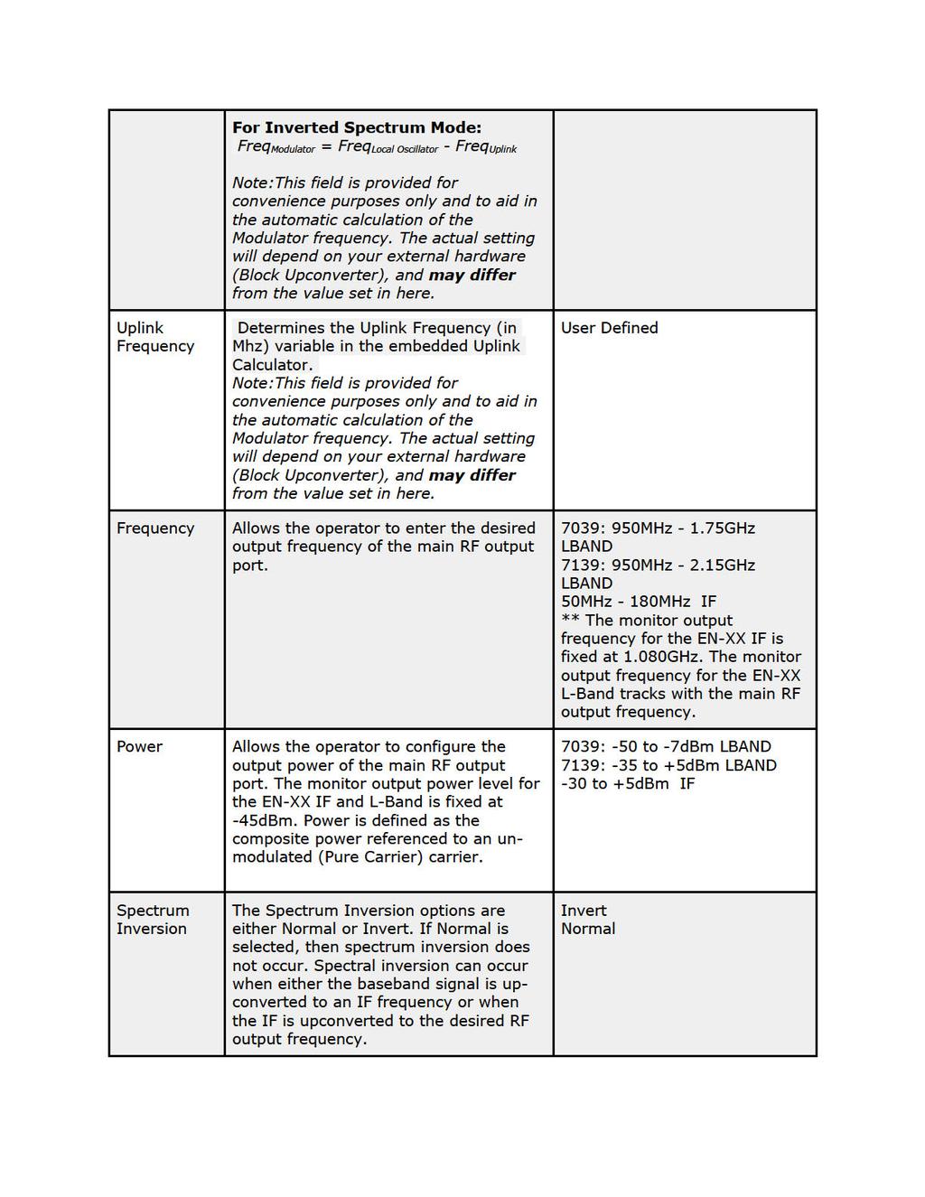
17 FEC Frame Rolloff Pilot Rate Priority Symbol Rate When operating in DVB-S2, the Frame Type options are either Normal or Short. The Normal 64,800-bit FEC frame provides better protection but introduces more latency compared to the Short 16,200-bit FEC frame. Therefore, the Short FEC frame type should be selected in applications where latency is critical and the longer frame type should be used to optimize protection. The Rolloff selection will determine the shape of the output filter. The occupied bandwidth of the modulated signal is the symbol rate multiplied by (1+α) where alpha (α) is the rolloff factor. By using a lower alpha, carriers can be spaced closer together on a given transponder or an increased symbol rate can be realized for a given bandwidth. When operating in DVB-S2, the Pilot options are either ON or OFF. When pilots are enabled, the total data throughput is reduced by approximately 3.0%. The Rate Priority control allows the operator to designate which rate will be kept constant. When the Symbol Rate is entered and Rate Priority is Symbol, the symbol rate is held constant and the Interface rate is calculated. When the Interface Rate is entered and Rate Priority is Interface, the interface rate is held constant and the symbol rate is calculated. The number of symbols transmitted per second. The amount of data per symbol is dependant upon the modulation type, e.g. QPSK, 8PSK, etc. Short Normal 5 (requires feature key) 10 (requires feature key) 15 (requires feature key) On Off Symbol Interface Range can be determined by feature key. Interface Rate The Interface Rate is the bit rate at the baseband interface. Range can be determined by feature key. Carrier Mode The Carrier Mode control allows the operator to select ON for normal operations or select one of four unmodulated carriers. The Pure Carrier Pure Carrier On Clock/8 Clock/4
18 option will provide an un-modulated output carrier at the desired frequency and output power. Other Carrier Mode options include Clock 4/8/16. Clock/16 10Mhz Clock 10 Mhz Clock Combined MODULATOR LINEUP Allows operator to generate or pass a 10Mhz signal. The signal can be generated internally or sourced externally. *** This is a special order option. If your unit does not have the functionality the setting will read N/A Allows the operator to choose whether or not to combine the 10Mhz signal with the L-Band output. *** This is a special order option. If your unit does not have the functionality the setting will read N/A This feature enables the operator to quickly view and/or configure select modulator RF output parameters. OFF ON EXTERNAL UNCOMBINED COMBINED Carrier Mode: PURE_CARRIER or ON Transmit: ENABLED or DISABLED Output Power: User defined in 0.5dB incr. Output Frequency: User defined in 1.0MHz incr. IP Tx Menu Note: this is a parallel menu. It has four index. Use the left or right arrows to navigate to desired index. Item Function Options Mode Enables IP Egress. Off Send IP Tx Mode Switches from UDP/RTP and TCP UDP/RTP TCP Tx IP Address The IP Address of which the Multicast or Unicast is broadcast. Multicast addressing supports the transmission of a single IP datagram to multiple receivers. Valid Multicast addressing range is XXX.XXX to user-defined; numeric field in format xxx.xxx.xxx.xxx
19 Tx Port Tx GW Address DVB per IP RTP FEC Mode FEC L FEC D TOS 239.XXX.XXX.XXX. Unicast addressing sends a single IP datagram to only one receiver. The Unicast address will be the unique IP of the receiving device. port assignment used for transmitting a multicast The Unicast Gateway automatically handles IP routing for unicast transmissions. This must be configured if the outgoing unicast requires a different gateway from the configured system default gateway. A route is automatically added when the unit is configured for transmit and a Unicast Gateway exists. The route is deleted if set to or Multicast Mode set to OFF. Configures the amount of DVB transport stream packets ( 188 bytes per DVB packet ) per IP packet payload allows for sequence numbering and timing; editable if Multicast Mode is set to 'Send' Forward Edge Correction; selects on/off. When selected, sends two FEC RTP streams in addition to a source RTP stream enabling a receiver to reconstruct missing packets in the source stream. affects the maximum burst packet loss that can be recovered Note: The product of FEC L and FEC D cannot exceed a value of 100 defines latency involved in burst recovery Allows the operator to sets the TOS bits in the IPv4 header of the TSoIP payload user-defined using the numeric keypad user-defined; numeric field in format xxx.xxx.xxx.xxx On Off OFF ON MAXBURST BURST LOWLATENCY = Normal service 2 = Minimize monetary cost 4 = Maximum reliability 8 = Maximize throughput
20 TTL Tx Connector Time-to-Live; specifies the number of iterations or transmissions the packet can undergo before it is discarded sets the physical connector (on the rear of the unit) to use for multicast transmit purposes on the indicated encode channel. 16 = Minimize delay user-defined using the numeric keypad Ethernet GigE Video Menu Note: There are several video encoding options marked by an * that pertain to EN100-VE1 and EN100-VE2 hardware options. EN-100 can be ordered with either VE1 (1080p AVC 8- bit 420) encoder module and/or VE2 (1080i AVC/MPEG2 10-bit 422) Item Function Options Input SDI Mode CODEC Entropy Coding Allows the operator to select which input the video will be sourced from. *depending on installed / selected Video Encoder option Optical may not be listed. Optical SDI input is a feature only supported by EN-100-VE1-01 model. Allows the operator to force the SDI receiver into a specified mode. *depending on installed / selected Video Encoder option HD3G may not be listed.* HD3G is a feature only supported by EN-100-VE1-01 model. Allows the operator to select between available CODECs *MPEG2 and H.264_10bit is a feature only supported by EN100-VE model Allows the operator to set the entropy coding settings *H.264 encoding only, Auto mode will use CABAC at video SDI COMPOSITE OPTICAL AUTO SD HD1.4G HD3G MPEG2 H264 H264_10BIT CABAC CAVLC AUTO
21 Chroma Deblock Filtering *EN-100-VE2 Only Video Field Coding *EN-100-VE2 Only Video Rate Autofill Latency bitrates <= 30Mbits/sec and CAVLC at rates > 30Mbits/sec. Allows the operator to set the encoder chroma type. *Chroma is forced to 422 when H264_10BIT is the selected codec. Allows the operator to turn deblock filtering on and off *H.264 encoding only Allows the operator to choose between different types of video field coding *H.264 encoding only The rate at which video is being encoded. Video bitrate changes are not dynamic. They take effect at the start of the next encode session. When Video AutoFill is turned ON, the encoder will calculate and use the max video bit rate for the current TransMuxRate setting. This is recommended. If Autofill is set to OFF the encoder will use the manual setting for the video bitrate. It is dependent upon the video rate, frame size/rate (NTSC,PAL,HIGH-DEF) and GOP structure. Long IBBP GOPs will produce higher latency over short IP GOPs. Short IP GOPs at lower bit rates produce lower quality video. *1,2, and 3 Frame latency is a feature only supported by EN100-VE2-01 model ON OFF AUTO FIELD FRAME ADAPTIVE *If video autofill is enabled, this value will change based on other variables. ON OFF LONG: Latency will measure close to 1 second. NORMAL: Should be used for distribution and standard contribution transmissions. Latency is approximately 1/2 second. LOW: Latency is approximately 3 frames less than NORMAL. VERYLOW: Latency is approximately 5 frames less than NORMAL. 3FRAME/2FRAME/1FRAME Feature keyed option that provides super low end-to-end latency when paired with an RD-60/RD-70. GOP settings are ignored. Interoperability with other vendor decoders is not guaranteed in these modes.
22 Latency Trim Fault Mode Fault Resolution Aspect Ratio AFD Use this setting in conjunction with the Latency setting to fine tune the latency in order to match various manufacturers latency settings. The setting is rounded down and applied in video frame multiples (a +50 msec offset would result in the following.. one additional frame delay with frame material and two additional frame delays with frame material). The user can select encoder behavior during video loss. The encoder can stop encoding, encode black, or generate a combination of Black, Bars, Tones and Service ID. Allows the operator to select what resolution to encode at during fault mode. Aspect Ratio is the ratio of horizontal lines to vertical lines in the encoded image.options are: - Wide Screen Signaling (WSS) reads incoming WSS flag and adjusts aspect ratio accordingly. - 4 X 3 defaults standard definition to 4 X 3 display X 9 defaults standard definition to 16 X 9 display. Aspect Ratio is related to Active Format Descriptor (AFD). It is recommended to set AFD to WSS if Aspect Ratio is WSS. Active Format Descriptor is data that can be sent in a MPEG video stream that provides information about the aspect ratio and picture characteristics within the stream. AFD compatible display or STB/IRD is required. AFD is related to Aspect Ratio. Aspect Ratio defines pixel aspect ratio as encoded. AFD is used by Max range is -400 to +200 and is constrained based on the ENCODELATENCY" setting (NORMAL) and current video mode. OFF BARS BARSTONES BARSOVERLAY BARSTONESOVERLAY 480I I50 720P P I I50 4x WSS *This is not a scaling option. Output display is completely dependent on input signal OFF WSS BOX16:9_T BOX14:9_T BOX16:9_C AS_CODEDFRAME 4:3_C 16:9_C 14:9_C 4:3_SP_14:9_C
23 GOP Type GOP Structure GOP Size SD Video Mode downstream decoding devices to properly display pixel aspect ratio on displays with differing aspect ratios. GOP Type can be set to open or closed. An OPEN GOP uses referenced pictures from the previous GOP at the current GOP boundary. A CLOSED GOP starts with an I Frame and subsequent B Frames do not rely on I or P frames from the previous GOP. GOP Structure sets the format Group-of-Pictures will use; the order of interframes and the various types of picture frames that will be used. GOP Size is the distance between two full image frames (I-Frames) in a GOP Structure. Configures the encoder for NTSC or PAL video. *This is only affects the incoming SDI feed if it is SD or if the input is Composite. 16:9_SP_14:9_C 16:9_SP_4:3_C Open Closed I IP IBP IBBP user-defined using the numeric keypad range = 1-30 NTSC PAL PALM PALN 3-D Sync Mode Enables multiple ADTEC Encoders to be synchronized. One unit is designated as 'master' which is tracked synchronously by units that are designated as 'slave'. The synchronization is transmitted over an ethernet connection using broadcast packets. OFF GENERIC MASTER MASTER GROUP 1-9 GENERIC SLAVE SLAVE GROUP 1-9 Audio Menu Item Function Options << 1-2 >> Parallel Menus. Surround Sound Determines the surround sound mode DD,DD-06,AAC-LC,AAC-HEv1,AAC-6,
24 Input Mode Type Rate << 1-8 >> Parallel Menus. Selects the audio input to use during encoding. Allow you to configure your device to Encode per audio or Passthru Defines the type of audio to encode or pass. The Audio Rate is the bitrate for audio encoding / transport and depends on mode selected. Analog SDI AES Off Encode Passthru DD = Dolby Digital AC3 MU = Musicam Layer II DE = Dolby E LP = Linear PCM DD-06 = Dolby Digital, PMT stream type 0x06 MU-04 = Musicam Layer II, PMT stream type 0x04 user-defined using the numeric keypad If MPEG 1 Layer 2, the available rates are 32, 48, 56, 64, 80, 96, 112, 128, 160, 192*, 224, 256, 320, 384 kbits/sec. If Dolby Digital AC3, the available rates are 56, 64, 80, 96, 112, 128, 160, 192*, 224, 256, 320, 384, 448, 512, 576, 640 kbits/sec. Note: * For MPEG 1 Layer 2 and Dolby Digital AC3, the recommended lowest rate for professional applications is 192 kbits/sec. In Dolby-E mode, do not set this value. The bitrate will be autodetected. Level Controls the volume level in dbs user-defined using the numeric keypad range = -18 dbs to 8 dbs in increments of 1 Analog Audio Level Sync Control the volume level -15 to +15 (dbs) in 1 db increments for AUDIO 1 and 2 only Audio Sync sets the audio sync offset. This measurement is in milliseconds, and works only on This trims the level on the analog audio path (only) to accommodate external audio gear variability. +/- 800
25 Musicam Mode analog audios. Allows the operator to choose how to encode left and right analog audio inputs. STEREO MONO DUALMONO IFB This is a low latency audio path for communications to a remote van or studio using the same distribution path. It requires a special IFB receiver or manual PID selection with a standard IRD. Note: There is no PID reference in the PMT for this functionality. It is considered a ghost PID. It is also not lip-sync aligned with video. OFF ON GHOST SDI Pair SDI Clock Source ECC Words Audio Level B Allows the operator to route embedded audio from SDI input to the specified audio encoder. The embedded audio clock source configuration determines whether to use the embedded clock phase words or derive from video clock. Default is EMBEDDED. If the SDI source has problem (or noncompliant) embedded audio clock phase words, then choose the video clock as the source. Note that choosing the video clock requires that all audio channels are embedded in a fully synchronous fashion. Default is ON. Select OFF if the SDI source has problematic (or noncompliant) ECC words. The Level B configuration determines which SDI link to deembed audio when using 3G-SDI Level B sources. 1-8 EMBEDDED VIDEO OFF ON LINKA LINKB PIDs Menu Item Function Options Transport Sets the Transport Stream ID in PAT and other 0x0001-0x1FFE
26 Stream ID tables in the egress transport stream. PMT PID PCR PID Video PID Audio PID 1-8 Configure this value in Hex. PMT PID refers to the PID of the Program Map Table (PMT). Program Map Tables are used to describe the properties of a single program. Programs periodically provide a Program Clock Reference, or PCR, on one of the PIDs in the program. This is also known as the master clock. The PCR PID identifies the packets which contain PCR adaptation fields. Video PID identifies packets containing the video Packetized Elementary Stream data. Identify packets containing audio content for the specified channels user-defined using the numeric keypad user-defined using the numeric keypad user-defined using the numeric keypad user-defined using the numeric keypad Teletext PID Teletext PID identify packets containing teletext information. user-defined using the numeric keypad VITC PID AMOL PID Splice PID Sets the Program ID (PID) for the ANC (H & V). ANC Data captured from HD-SDI source is carried per SMPTE Typically this is used to carry VITC. If VITC and LTC are carried concurrently, LTC is dropped. Automated Measurement of Line Ups; identifies packet which contains AMOL (NTSC) information Only applies to 525 line (NTSC) video. Splice PID is used for Cablelabs SCTE 35 Splice Point identification. user-defined using the numeric keypad user-defined using the numeric keypad user-defined using the numeric keypad VBI Menu Item Function Options Source Closed Caption selects the source of Vertical Blanking Interval spacing activates (or deactivates) closed-captioning and specifies closed-captioning standard to be used Composite SDI Off DVS157 ASTC ASTC708 ASTCConvert
27 VITC Mode Allows the operator to choose to look at Ancillary or waveform data for captions OFF ON Profile Menu Command Function SELECT SAVE DELETE The select submenu lists all stored profiles and allows loading The save submenu saves a profile with a user designated name The delete submenu deletes a profile from the available list CAS Menu Control Mode Clear Session Word Encrypted Session Word User ID 1 User ID 2 Function select between off, BISS-1, and BISS-E encryption. options: OFF, BISS 1, BISS_E_USER_ID_ONE, BISS_E_USER_ID_TWO MODE BISS 1 uses a 12-digit hexadecimal Clear Session Word. MODE BISS E XXX uses a 16-digit hexadecimal Encrypted Session Word used in BISS-E Mode only; the 14-digit hexadecimal User ID used for encryption used in BISS-E Mode only; the 14-digit hexadecimal User ID used for encryption (secondary)
28 System Menu Login Units ship with the front panel logged in by default. If you become logged out and are prompted for a password, use the following key sequence for access. Action Press <Select> Press <Up> arrow Press <Select> Press <Enter> Press <Right arrow> Press <Enter> Duration The front panel also has a login duration feature. This setting Allows the operator to specify a time frame (in minutes) until the unit will automatically log itself out. Action Press mode until you see the System Menu. Press <Select> Press the <Down> arrow Press <Select> Using the <Up> and <Down> arrows, select the value you wish. Press <Enter> to save your selection Possible Configurations: 0 (Zero): The unit will not automatically log out. 1-9: The duration of time, in minutes, before the unit logs out, if no input is received. Backlight Dim Delay Action Press <Select> Using the <Up> and <Down> arrows, select the value you wish.
29 Press <Enter> to save your selection Network Sub Menu Item Function Options Ethernet IP Address Ethernet IP Mask Ethernet DHCP GIGE IP Address GIGE IP Mask GIGE DHCP Gateway IP Address Stealth IP Address This is the address of your device on your network specific to the Ethernet Port. Defines the unit relative to the rest of your network. The Dynamic Host Configuration Protocol allows your device to self-locate network Ethernet parameters. This is the address of your device on your network specific to the GigE Port. Defines the unit relative to the rest of your network. The Dynamic Host Configuration Protocol allows your device to self-locate network GigE parameters. The gateway is a routing mechanism that passes traffic between different subnets and networks. This is a security feature that allows only the designated Stealth IP Address to communicate with the unit for FTP and other services. This control allows one-point override access to the Stealth IP Address. user-defined using the numeric keypad Default is user-defined using the numeric keypad Default is On (finds own DHCP Address) Off (defaults to last entered IP Address) Default is OFF user-defined using the numeric keypad Default is user-defined using the numeric keypad Default is On (finds own DHCP Address) Off (defaults to last entered IP Address) Default is OFF user-defined using the numeric keypad Default is user-defined using the numeric keypad Default is Using all 0s effectively turns this function off.
30 Time Sub Menu Item Function Options Time Defines system time user-defined using the numeric keypad Timezone Defines the time zone the unit operates in NTP Sub Menu Item Function Options NTP Status Network Transfer Protocol Read-only NTP IP Address IP address designated for Network Transfer Protocol user-defined using the numeric keypad Default is Using all 0s effectively turns this function off. Alarm Item Function Options Event Record Log of events outside of regular operating parameters scroll up and down to view log items SNMP Sub Menu Item Function Options SNMP Read-only community Read-write community Trap community Controls the status (ON/OFF) of the Simple Network Management Protocol (SNMP) feature. We support SNMPv2c version. The Simple Network Management Protocol (SNMP) Read-Only Password. Default Value: "adtec" The Simple Network Management Protocol (SNMP) Read-Write Password. Default Value: "none" The Simple Network Management Protocol (SNMP) trap community. Default Value: "public" OFF ON CLEAR user-defined user-defined user-defined
31 Trap sink The Simple Network Management Protocol (SNMP) trap sink. Default Value: " " Enter the IP address of your SMNP trap sink server. Com2 Item Function Options Com2 Settings RS-232 terminal monitor for communicating with the internal host motherboard for diagnostics NONE NONE NONE NONE NONE Default is None Feature Sub Menu Item Function Options Permanent ID Temporary ID Key status This is one of the unique IDs for your unit. This number along with your serial number are used to generate permanent feature keys. This is the other unique ID. It along with the permanente ID, and serial number are used to generate temporary feature keys. Depending on what keys you have and if they are temp or permanent they will be listed here. read only value read only value read only values with countdown for temp keys. Name Item Function Options Name Displays and allows editing of Enter Ascii characters.
32 the units name. This becomes the units host name for networking purposes. Firmware Item Function Options Firmware Displays the currently running firmware version Read-Only Back Panel Connector Description Power 1 & 2 Redundant AC Power, Standard 3 pin computer power plug (Auto range VAC Input) GigE / Gbe MPEG2 or RTP multicast transport egress port (SMPTE 2022) (A) Main (B) Monitor (C) 10MHz Clock RF output, 50 Ohm BNC L-Band Model: Frequency range 950 MHz to GHz, Power Level -50 to -7 dbm IF Model: Frequency range 50 MHz to 180 MHz, Power Level -30 to +5 dbm RF output, 50 Ohm BNC L-Band Model: Fixed power level at -45 dbm IF Model: Fixed power level at -45 dbm, fixed frequency at 1.08 GHz BNC 50 Ohm connector for external 10MHz reference input COM2 API Serial Communication Interface ** COM1 ETH0 10/100 Serial Port Used for Troubleshooting (Terminal) 10/100 base T ethernet interface (Monitoring/Management) DVC Parport 9-pin parallel I/O interface for control systems ** RS422 CTRL Not Currently Supported ** GPIO Transport Out (ASI) 1-3 CVBS In Tally and Control Port 75 Ohm source ASI x3 per EN Up to 100 Mbps. 75 Ohm terminated Standard Definition Composite Video Input
33 HD/SD SDI In 75 Ohm terminated Input, Video & Audio (SMPTE 259M for SD & SMPTE 292M for HD) BNC ** Use this input for ASI Receive mode AES Audio In Ohm AES-3 per AES Analog Audio In Stereo Pairs 1 and 2 (600 Ohm Balanced) ** SFP SFP slot used for single channel optical receiver module GPIO and Parport information The GPIO port allows encoder stop / start control and TTL voltage output for monitoring systems. TTL pin behavior by default is HI (3V) when encoding and LO (0V) when not encoding. Logic of the TTL pin can be configured based upon video detection, encode status, and manual override with the PP9 API command. Please view API details for further configuration information. The DVC Parport allows custom events to be programmed upon input pin voltage change. It contains 4 available inputs for custom commands. Please contact technical support for advanced usage in programming the parallel port. GPIO Pinout PIN Designation Function 1 NC No Connect 2 D3 reserved for future functionality 3 D2 RECORD ( start encoder ) ( input ) 4 D1 STOP ( stop encoder ) ( input ) 5 D0 reserved for future functionality 6 NC No Connect 7 5VDC +5V DC 8 GND ground 9 TTL Tally HI (3V) or LO(0V) based upon PP9 logic ( output )
34 Parport Pinout PIN Designation Function 1 NC No Connect 2 D3 Data bit 3 ( input ) 3 D2 Data bit 2 ( input ) 4 D1 Data bit 1 ( input ) 5 D0 Data bit 0 ( input ) 6 NC No Connect 7 5VDC +5V DC 8 GND ground 9 NC No Connect
35 Chapter 3 - Getting Connected Introduction to the Control Application A web-based control software application comes pre-installed on the EN-100. Compatible browsers Firefox (recommended) MS Internet Explorer Safari Chrome Ethernet Access To begin, you will need to connect to your EN-100 via ethernet directly, or by adding the EN-100 to your local area network.the default address for all Adtec devices is To connect directly to the device, make sure that your computer and the device have IP addresses within the same IP class range (ex for the device and for your computer). If you need to change the IP address of the device, this can be done via the front panel, System > Network menu. Using a CAT5 crossover cable, connect one end to your computer and the other to the Ethernet port found on the processor section of the back panel. (Some computers can auto negotiate the connection and a crossover may not be necessary.) To add the device to a LAN, connect a standard CAT 5 Ethernet cable to your network router and then to the Ethernet port on the back of the device. If your network is DHCP enabled and you prefer that over a static IP, you can turn on DHCP for the device via the front panel, System > Network menu. Zero Configuration Access Adtec Digital has adopted zero-configuration networking technology, streamlining the setup and configuration processes for our products. The use of this technology enables automatic discovery of Adtec devices and services on an IP network. Used in tandem with the webbased control and configuration applications we can now provide 1-click access to any device. By using the built-in Bonjour locater in Apple's Safari browser or the plug-ins readily available for IE or Firefox browsers, users can locate all of the Adtec devices on a network by referencing the serial number on the back of the device. Clicking on the unit in the Bonjour list will re-route you to a login page. If you do not wish to use Bonjour, you can
36 reach the device s web application by pointing your browser to the IP Address of the device. Ex. Login Once you reach the default login page for the web-based application, you will need to login by pressing the login button. You will be prompted for a username and password. The default username is adtec. The default password is none. The left-hand panel of the application will report current status in real-time while the right panel tabs will allow you to configure your device. As you navigate through the web application look for the? icons associated with each parameter. By clicking on these question marks, you can view additional information about how the parameter is used. Upgrading Via Web User Interface Periodically, we will provide firmware updates to our products via our website. ( To upgrade your device, download the firmware file from our website and store it locally. Login to the web-based application and navigate to the Upgrade > Firmware tab. Click on the upload button located at the top right of the application. Select the firmware file from your local machine and wait for it to upload. Once it has finished uploading, it will appear in the Available Versions list. Click on the Install button associated with the new file. Wait for it to completely extract and become available in the Installed Versions List. Once available there, simply click on the Select button associate with the new firmware and wait for your device to reboot.
37 Upgrading Via FTP & Telnet For those times when using the web user interface is not convenient, you can upload the firmware file via ftp and then extract and select into it via Telnet. File Transfer Protocol (FTP) FTP connections can be made to the Adtec device using any ftp client. Host: <ipa of the unit> Default Username: adtec Default Password: none Port: 21 You will want to drop the firmware file in the media/hd0/media folder. Telnet (standard 23 port) To connect to your unit using a terminal session you will need to set the IP address of the unit. See earlier instructions on setting the IP via the front panel. Using a terminal window, complete the following: Step Action 1 Type 'telnet x.x.x.x' in a terminal window, without quotes, where x.x.x.x is the IP address of the unit. 2 Press <Enter>. 3 When prompted for a username, enter adtec. 4 When prompted for a password, enter none. Once you see "User 'adtec' connected", the session is open and you may issue API commands to the unit. To extract and select into the new firmware version you have uploaded, issue the following commands. *.sysd version search Copy the line designating the location of the new file. Then type: *.sysd version extract copied path to new file Wait for the extraction to complete. Once complete, type the following command: *.sysd version Copy the line referencing the firmware version you wish to use and then issue the following command.
38 *.sysd version select copied new firmware version Once you press enter, this will reboot your device into the new version. See series of commands as they occur during this process below. Last login: Wed Sep 14 12:08:53 on ttys000 Macintosh:~ user$ telnet Trying Connected to Escape character is '^]'. Adtec Resident Telnet Server... UserName: adtec PassWord: User adtec connected *.sysd version search OK /media/hd0/media/en-80-v _rc.nfcms.tgz *.sysd version extract /media/hd0/media/en-80-v _rc.nfcms.tgz OK Validating Firmware: EN-80-v _RC.nfcms.tgz Firmware file validated. Extracting firmware: EN-80-v _RC.nfcms.tgz long series of extraction messages Extraction complete. Moved usr/adtec/en-80 to /opt/pkg Extraction successful. *.sysd version OK adtec/en-80/ (*** current selection ***) adtec/en-80/ adtec/en-80/ _rc *.sysd version select adtec/en-80/ _rc OK Found Required GNU for adtec/en-80/ _rc: gcc glibc Updating OEM version to adtec/en-80/ _rc. Updating GNU to gcc glibc Updated GNU to gcc glibc Set /opt/pkg/var/oem_prev for migrate: /opt/pkg/usr/adtec/en-80/ Current autoboot partition: 2
 is typically used in transmissions that require time code from the originating source to be")
39 Updating the primary kernel. Creating a boot partition using the "primary" directory... Flushing /dev/hde device buffer, please wait. Chapter 4 - Operational How-Tos How to Use Vertical Interval Time Code Vertical Interval Time Code (VITC) is typically used in transmissions that require time code from the originating source to be preserved. It was originally developed for analog television recording systems, but has new standards for transmitting in digital systems (SMPTE-12M-1 / SMPTE-12M-2). Preserving time code is beneficial for future editing and playback of captured material. EN-XX-series devices can pass VITC ancillary data as part of the ANC PID. The ANC PID is a separate PES located in the transport stream. Additionally, time code within the GOP of the video will also be adjusted at encoder start up to match the incoming ancillary VITC. VITC data packets will contain a DID of 0x60 and an SDID of 0x60. The VBI tab contains an SDI ancillary inspector that allows users to view ANC data present at the input. This tab can be viewed for verification of present ancillary data at the SDI input. To enable VITC passthrough: Step Action 1 On the VBI Tab in the Web GUI Control Application, configure the "VBI Source" for <SDI>. 2 On the PID Tab in the Web GUI Control Application, select the <On> setting for "ANC PID Active".

40 How to Configure Passthru Audio Adtec EN-Series encoders have the flexibility to meet many demanding audio requirements. Each model contains specific encoding options, but every Adtec EN-Series encoder supports two audio passthrus. An audio passthru consists of a compressed bitstream ( Dolby E 20 Bit / Dolby E 16 Bit / Dolby Digital / Linear Acoustic Stream Stacker 2 ) or an uncompressed stereo pair ( LPCM ) from an embedded SDI or AES input passed into the egress transport stream ( IP, RF, ASI ). The EN-100 supports four passthru audios on the first four audio inputs. The SDI Matrix and ASI Transport Stream PID configurations allow for custom configurations if required. Every audio input engine has an internal SDI Matrix to route any audio to one or multiple inputs. Each audio engine output can be assigned a user configurable PID in the transport stream to meet any job requirement. If the passthru audio is coming in via embedded SDI, the SDI Audio Matrix may be used in conjunction with the PID tab to manipulate the input and output routing.

41 To enable Audio passthru for Audio 1: Step Action 1 On the Audio -> Audio 1 in the Web GUI Control Application, configure the "Audio Mode" for <PASSTHRU>. 2 Configure the Audio Input for the desired input <AES> or <SDI>. note: If using SDI, select the proper audio pair from the SDI audio matrix. 3 Select the type of audio from the Type drop down. <Dolby Digital>, <Dolby E>, or <Linear PCM / E2>. note: If Dolby E or Dolby Digital is valid at the input, the bit depth and bitrate are automatically determined after clicking Apply. 4 On the PID tab, type in the desired Audio PID for Audio 1. 5 Adjust other audio PID s if necessary. Common Passthru Problems: Dolby E Line Placement and/or Dolby E Continuity Count Errors: Dolby E audio compression technology is designed so that 1 Dolby E audio frame corresponds to 1 Video frame. This 1:1 ratio of video and audio timing was designed to assist in Video editing and seamless cuts without losing audio data. Due to the crucial and
EN-100 USER GUIDE. 10-bit/1080p Capable MultiCODEC Encoder. Includes modulator versions - LB, IF & IF/LB/10M
 EN-100 10-bit/1080p Capable MultiCODEC Encoder Includes modulator versions - LB, IF & IF/LB/10M USER GUIDE 3.00.27 Table of Contents Table of Contents Trademarks & Copyrights Electrical Device Compliance
EN-210 USER GUIDE. Includes modulator version - IF/LB/10M
 EN-210 10-bit MultiCODEC Encoder Includes modulator version - IF/LB/10M USER GUIDE 3.00.27 Table of Contents Table of Contents Trademarks & Copyrights Electrical Device Compliance Notices Safety Warnings
EN-200 USER GUIDE. 1080p AVC Low Latency Encoder. Includes modulator version - IF/LB/10M
 EN-200 1080p AVC Low Latency Encoder Includes modulator version - IF/LB/10M USER GUIDE 3.00.27 Table of Contents Table of Contents Trademarks & Copyrights Electrical Device Compliance Notices Safety Warnings
EN-91 / EN-91P USER GUIDE. MPEG 4 DSNG Encoder. Includes modulator versions - LB and IF v
 EN-91 / EN-91P MPEG 4 DSNG Encoder Includes modulator versions - LB and IF USER GUIDE 01.29.15 - v1.02.29 Table of Contents Table of Contents Trademarks & Copyrights Electrical Device Compliance Notices
Multi-CODEC 1080P IRD Platform
 Multi-CODEC 1080P IRD Platform RD-70 The RD-70 is a 1080P multi-codec very low latency MPEG 2 and MPEG 4 AVC/H.264 high definition IRD. The ultra-low delay mode requires the use of Adtec s EN-91 1080i,
EN-30 USER GUIDE. Dual Channel Capable HD/SD MultiCODEC DSNG Encoder w/ optional IF/LB/10Mhz Modulation
 EN-30 Dual Channel Capable HD/SD MultiCODEC DSNG Encoder w/ optional IF/LB/10Mhz Modulation USER GUIDE 2.01.15 Table of Contents Table of Contents Trademarks & Copyrights Electrical Device Compliance Notices
EN-31 USER GUIDE. Dual Channel Capable HD/SD MultiCODEC DSNG Encoder w/ optional IF/LB/10Mhz Modulation. v
 EN-31 Dual Channel Capable HD/SD MultiCODEC DSNG Encoder w/ optional IF/LB/10Mhz Modulation USER GUIDE v2.01.14 1 Table of Contents Table of Contents Trademarks & Copyrights Electrical Device Compliance
MediaKind RX
 MediaKind RX8330 The MediaKind RX8330 Distribution Receiver provides feature-rich multi-format standard definition decoding capability with high quality SDI output for video distribution applications.
MediaKind RX8200 SkyUK CA
 MediaKind RX8200 SkyUK CA Advanced Modular Receiver - SkyUK CA The MediaKind RX8200 Advanced Modular Receiver is the industry standard Integrated Receiver Decoder (IRD) for decoding content feeds. RX8200
Z-IP Stream 004/008. User Guide and Installation Manual. Four or Eight Input QAM Encoder / Modulator
 Z-IP Stream 004/008 User Guide and Installation Manual Four or Eight Input QAM Encoder / Modulator MPEG-2 / H.264 HD ENCODER with QAM /IP/ & ASI Outputs Contents Safety Precautions... 3 Package Contents...
MediaKind RX8320 Receiver
 MediaKind RX8320 Receiver ATSC Broadcast Design As local terrestrial broadcasters begin to phase out their analog broadcasts and transition to an all-digital environment, the need to maintain access to
Advanced Receiver Decoder Card
 Advanced Receiver Decoder Card AG 5800 opengear Module SATELLITE INPUT OVERVIEW MPEG/IP INPUT ASI INPUT The AG 5800 card-based receiver decoder provides an ideal solution for 4:2:2 video decoding where
10-bit 1080P Integrated Receiver Decoder. v
 RD-71 10-bit 1080P Integrated Receiver Decoder USER GUIDE v2.00.18-08.10.2015 1 Contents Contents Introduction Rack Installation Back Panel DB9-M Analog audio output pinout COM1/COM2 to DB9 Serial Adapter
AVP 3000 Voyager.
 AVP 3000 Voyager The AVP 3000 Voyager is MediaKind s sixth generation DSNG product and is the most flexible and scalable news gathering system on the market, reflecting MediaKind s technology leadership
Operation and Installation Guide
 Operation and Installation Guide HDS2800 Series Encoder Modulator High Definition (HD) Digital COFDM MPEG2 and H.264 Modulator with IP Multicast. 19 Rack Mount Revision 4.0 Firmware version Released File
HD-1603 Single Input MPEG-4 DVB-T HD Encoder/Modulator User Guide and Install Manual
 ZyCastR digi-mod HD Range digi-mod HD-1603 www.digi-modbyzycast.com HD-1603 Single Input MPEG-4 DVB-T HD Encoder/Modulator User Guide and Install Manual Table of Contents www.digi-modbyzycast.com Safety
IP LIVE PRODUCTION UNIT NXL-IP55
 IP LIVE PRODUCTION UNIT NXL-IP55 OPERATION MANUAL 1st Edition (Revised 2) [English] Table of Contents Overview...3 Features... 3 Transmittable Signals... 3 Supported Networks... 3 System Configuration
Cisco D9859 Advanced Receiver Transcoder
 Data Sheet Cisco D9859 Advanced Receiver Transcoder Deliver MPEG-4 high-definition (HD) services to MPEG-2 cable TV (CATV) headends with the Cisco D9859 Advanced Receiver Transcoder. The Cisco D9859 platform
RD-70. USER GUIDE v bit / Multi-CODEC 1080P Receiver / Decoder. Includes demodulator versions - ADV, LB and PRM
 RD-70 10-bit / Multi-CODEC 1080P Receiver / Decoder Includes demodulator versions - ADV, LB and PRM USER GUIDE v2.02.21 Contents Contents Trademarks & Copyrights Electrical Device Compliance Notices Safety
MediaKind RX8200 Configuration Packs
 MediaKind RX8200 Configuration Packs The RX8200 Advanced Modular Receiver is the world s bestselling IRD. Now with DVB-S2X and HEVC capability makes it the most future-proof. Broadcasters need to deploy
Broadcast Satellite Modulator
 M6100 Modulator Broadcast Satellite Modulator The M6100 Broadcast Satellite Modulator is the latest generation satellite modulator built from the ground up for contribution, distribution and direct-to-home
EN-20 USER GUIDE. Dual Channel HD/SD MultiCODEC SDI Encoder w/ optional QAM Modulator
 EN-20 Dual Channel HD/SD MultiCODEC SDI Encoder w/ optional QAM Modulator USER GUIDE 2.01.02-11.06.13 Contents Contents Trademarks & Copyrights Adtec Digital Support & Service Telephone and Email Support
Cisco D9859 Advanced Receiver Transcoder
 Deliver MPEG-4 high-definition (HD) services to MPEG-2 cable TV (CATV) headends with the Cisco D9859 Advanced Receiver Transcoder. The Cisco D9859 platform (Figures 1 and 2) extends the distribution options
7881IRDA Series QUICK START GUIDE
 7881IRDA Series QUICK START GUIDE Copyright 2013-2015 EVERTZ MICROSYSTEMS LTD. 5292 John Lucas Drive, Burlington, Ontario, Canada L7L 5Z9 Phone: +1 905-335-3700 Sales: sales@evertz.com Fax: +1 905-335-3573
Cisco D9894 HD/SD AVC Low Delay Contribution Decoder
 Cisco D9894 HD/SD AVC Low Delay Contribution Decoder The Cisco D9894 HD/SD AVC Low Delay Contribution Decoder is an audio/video decoder that utilizes advanced MPEG 4 AVC compression to perform real-time
RD bit 1080P Integrated Receiver Decoder. USER GUIDE v
 RD-71 10-bit 1080P Integrated Receiver Decoder USER GUIDE v2.02.21 1 Contents Contents Application Diagrams Rack Installation Back Panel DB9-M Analog audio output pinout COM1/COM2 to DB9 Serial Adapter
Ultra-ViewRF 8HD Director Monitor. User Operation Manual
 Ultra-ViewRF 8HD 5.8GHz Wireless Director Monitor User Operation Manual 17.1.2013 v2_7 Video Equipment Rentals - VER 912 Ruberta Avenue Glendale, CA 91201 - U.S.A. Office 818-956-1444 Table of Contents
QRF5000 MDU ENCODER AND QAM MODULATOR
 Radiant Communications Corporation 5001 Hadley Road South Plainfield NJ 07080 Tel (908) 757-7444 Fax (908) 757-8666 WWW.RCCFIBER.COM QRF5000 MDU ENCODER AND QAM MODULATOR Installation & Operational Manual
AES/EOU R-AUDIO2 R-AUDIO1 L-AUDIO1 L-AUDIO2 CVBS CVBS OUT R-AUDIO1 R-AUDIO2 ASI OUT2 GPI/LS DATA
 160R-Base R-AUDIO1 R-AUDIO2 AES/EOU ASI OUT RF OUT RF IN L-AUDIO1 L-AUDIO2 CVBS ASI IN GPI/LS DATA 160R-AD GPI/LS DATA CVBS OUT R-AUDIO1 R-AUDIO2 ASI OUT2 ASI IN2 RF OUT2 RF IN2 RF OUT1 RF IN1 Introduction
ITV-EN460d MPEG-4 AVC Encoder
 ITV-EN460d MPEG-4 AVC Encoder The ITV-EN460d MPEG-4 AVC Encoder is a real time compression solution that delivers unrivalled HD and SD video quality. The solution provides operators with the most powerful,
Installation & Operational Manual
 Radiant Communications Corporation 5001 Hadley Road South Plainfield NJ 07080 Tel (908) 757-7444 Fax (908) 757-8666 WWW.RCCFIBER.COM QRF5000M MDU ENCODER Installation & Operational Manual Rev.A2 1. Introduction
SD4650 DVB-T HD MODULATOR. User Manual
 SD4650 DVB-T HD MODULATOR User Manual 0 TABLE OF CONTENT 1 GENERAL...2 1.1 Description...2 1.2 Specifications...3 2 INSTALLATION...4 2.1 What s in the Box...4 One power cable...4 2.2 Connection...4 2.2.1
AVE HOME FAGOR CVBS TO DVB-T ENCODER MODULATOR. Fagor Electr6nica
 AVE HOME CVBS TO DVB-T ENCODER MODULATOR FAGOR Fagor Electr6nica TABLE OF CONTENTS 1. SPECIFICATIONS... 12 1.1 Product Overview... 12 1.2 Appearance and Description... 12 1.3 Diagram... 13 1.4 Characteristics...
Simple Media Platform Quick Installation Guide V1.0-N. Simple Media Platform. Quick Installation Guide
 Simple Media Platform Quick Installation Guide 1. Installation Instruction 1.1 Mounting unit to a 19 rack When selecting the installation site, try to comply with the following: Protective Ground - The
MediaKind RX8200. Rev C.1018
 MediaKind RX8200 The RX8200 Advanced Modular Receiver is the world s bestselling IRD. Now with DVB-S2X and HEVC upgradeability it is also the most future-proof. Broadcasters need to deploy receivers for
Teletext Inserter Firmware. User s Manual. Contents
 Teletext Inserter Firmware User s Manual Contents 0 Definition 3 1 Frontpanel 3 1.1 Status Screen.............. 3 1.2 Configuration Menu........... 4 2 Controlling the Teletext Inserter via RS232 4 2.1
Operation and Installation Guide
 Operation and Installation Guide HDS2800 Series Encoder Modulator High Definition (HD) Digital COFDM MPEG2 and H.264 Modulator with IP Multicast. 19 Rack Mount Wall Mount Revision 0.1 Firmware version
MyM-3S Micro Master. Installation Guide. English. design for TV
 MyM-3S Micro Master Installation Guide design for TV 1 CONTENT 1. Introduction 2. Unpacking the unit 3. Connections and indications 4. IP settings 5. Menus and settings 5.1 Overview menu 5.2 Input settings
DTE-1000 MPEG2 SD ENCODER
 DTE-1000 MPEG2 SD ENCODER MPEG2 system with IP and ASI output Technical documentation/instruction set/software manual Composed by: Merkl Tamás, Körmendi Ferenc, Gyebnár Zoltán Teletechnika Ltd. 7th Edition
DIGICAST DTVANE. DMB-9020 HD Professional IRD OVERVIEW
 OVERVIEW Conforming to MPEG-2(MP@ML), DMB-9020 HD Professional IRD supports DVB-S2 Tuner standard, and adopts high-quality decoding of MPEG-2, MPEG-4, and H.264 in broadcast level. Its CI descrambling
INT-DS2 DVB-S/S2 SATELLITE MODULATOR DVB MODULATOR
 INT-DS2 DVB-S/S2 SATELLITE MODULATOR Key Features In compliance with DVB-S/S2/DSNG and in partial compliance with DVB-S2x standards. Supporting up to 200Mbps at ASI and 80Mbps at TSoIP input. Capable to
Messenger Veta Receiver Decoder (MVRD)
") The most important thing we build is trust. Product Highlights Two Channel Maximal-Ratio Diversity Receiver Supports DVB-T and Narrow-Band 1 modes down to 1.25 MHz BW Provides Ultra-Low-Latency for Real-Time
The most important thing we build is trust. Product Highlights Two Channel Maximal-Ratio Diversity Receiver Supports DVB-T and Narrow-Band 1 modes down to 1.25 MHz BW Provides Ultra-Low-Latency for Real-Time
HD-1600 Single Input MPEG-4 DVB-T HD Encoder/Modulator User Guide and Install Manual
 digi-mod HD Range digi-mod HD-1600 www.resi-linx.com HD-1600 Single Input MPEG-4 DVB-T HD Encoder/Modulator User Guide and Install Manual Table of Contents Safety Precautions 2 Package Contents 2 Product
The RX8200 Advanced Modular Receiver is the world s bestselling IRD. Now with DVB-S2X and HEVC upgradeability it is also the most future-proof.
 Ericsson RX8200 Advanced Modular Receiver The RX8200 Advanced Modular Receiver is the world s bestselling IRD. Now with DVB-S2X and HEVC upgradeability it is also the most future-proof. Broadcasters need
Professional HD Integrated Receiver Decoder
 Professional HD Integrated Receiver Decoder User Manual V1.00-C Preface About This Manual This manual provides introductions to users about how to operate the device correctly. The content includes introduction
QRF5000 MDU ENCODER. Data Sheet
 Radiant Communications Corporation 5001 Hadley Road South Plainfield NJ 07080 Tel (908) 757-7444 Fax (908) 757-8666 WWW.RCCFIBER.COM QRF5000 MDU ENCODER Data Sheet Version 1.1 1 Caution Verify proper grounding
MyM Pro 3S/6S Installation guide
 MyM Pro 3S/6S Installation guide CONTENT 1. Introduction 2. Unpacking the unit 3. Connections and indications 4. IP settings 5. Menus and settings web ui 5.1 Overview menu 5.2 Input settings 5.3 Output
B. The specified product shall be manufactured by a firm whose quality system is in compliance with the I.S./ISO 9001/EN 29001, QUALITY SYSTEM.
 VideoJet 8000 8-Channel, MPEG-2 Encoder ARCHITECTURAL AND ENGINEERING SPECIFICATION Section 282313 Closed Circuit Video Surveillance Systems PART 2 PRODUCTS 2.01 MANUFACTURER A. Bosch Security Systems
DVB IP CONVERTER FOR IPTV HEADENDS with INTEGRATED RECEIVER & DECODER & REMUXER
 DVB IP CONVERTER FOR IPTV HEADENDS with INTEGRATED RECEIVER & DECODER & REMUXER PRODUCT DESCRIPTION The DMM-151/152 is a high-density, cost-effective modular DVB to IP gateway system and DVB streamer for
Portable TV Meter (LCD) USER S MANUAL
 USER S MANUAL") 1 Portable TV Meter User Manual (LCD) Portable TV Meter (LCD) USER S MANUAL www.kvarta.net 1 / 19 2 Portable TV Meter User Manual (LCD) Contents 1. INTRODUCTION... 3 1.1. About KVARTA... 3 1.2. About DVB...
1 Portable TV Meter User Manual (LCD) Portable TV Meter (LCD) USER S MANUAL www.kvarta.net 1 / 19 2 Portable TV Meter User Manual (LCD) Contents 1. INTRODUCTION... 3 1.1. About KVARTA... 3 1.2. About DVB...
DVB IP CONVERTER FOR IPTV HEADENDS with INTEGRATED RECEIVER & DECODER & REMUXER
 DVB IP CONVERTER FOR IPTV HEADENDS with INTEGRATED RECEIVER & DECODER & REMUXER PRODUCT DESCRIPTION The DMM-151 is a high-density, cost-effective modular DVB to IP gateway system and DVB streamer for IPTV
For flexible advertisement insertion configurations, this receiver provides four types of outputs:
 Product Overview The Cisco PowerVu Model D9850 Program Receiver (Figure 1) is designed for satellite content distribution applications requiring 4:2:0 video decoding. The receiver can receive digitally
HD4112 Quad HDMI MPEG2 HD DVBT Encoder Modulator U S E R M A N U A L
 HD4112 Quad HDMI MPEG2 HD DVBT Encoder Modulator U S E R M A N U A L HD4112 Manual Rev 1 Contents 1. GENERAL 1.1 Description 1.2 Specifications 2. INSTALLATION 2.1 What s in the Box 2.2 Connection 2.2.1
DVISm. DVISm - Mini Digital Video Insertion System. Quick Start Guide. Patent Pending
 DVISm Patent Pending DVISm - Mini Digital Video Insertion System Quick Start Guide Although every effort has been taken to ensure the accuracy of this document it may be necessary, without notice, to make
TV4U QUAD DVB-S2 to DVB-C TRANSMODULATOR
 INSTRUCTION MANUAL Features of the new DVB-C transmodulators line Through the use of the FPGA technology the transmodulators provides the highest performance at the lowest price. Four carriers are formed
OPERATING INSTRUCTIONS TOM-0431IP
 OPERATING INSTRUCTIONS TOM-0431IP Table of Contents FCC Information -------------------------------------------------------------------- 2 Safety and Environmental Precautions ------------------------------------------------
Thor Broadcast SDI-DVBT-IP & SDI-DVBT-IPLL Product Lines
 700-1200 ms 1080p60 70-125 ms (LL) H-4SDI-DVBT-IP H-4SDI-DVBT-IP 4x HD-SDI 1080p60 700-1200 ms 70-125 ms (LL) Data Sheet: H-1/4SDI-DVBT-IP User s Manual: H-1/4SDI-DVBT-IP Thor Broadcast SDI-DVBT-IP & SDI-DVBT-IPLL
IP-900 Series V02 SOFTWARE USER S GUIDE
 V02 SOFTWARE USER S GUIDE C134-E016-03 USING SAFELY Handling of This Manual This manual contains important information regarding the safe use of IP-900 series. Before using this product, please read this
OPERATION MANUAL. USF-1013DEMUX Digital Audio Demultiplexer. 2 nd Edition. Software Version Higher
 OPERATION MANUAL USF-1013DEMUX Digital Audio Demultiplexer 2 nd Edition Software Version 2.00 - Higher Precautions Important Safety Warnings [Power] Stop [Circuitry Access] Do not place or drop heavy or
HD Digital MPEG2 Encoder / QAM Modulator
 HD Digital MPEG2 Encoder / QAM Modulator HDMI In QAM Out series Get Going Guide ZvPro 800 Series is a one or two-channel unencrypted HDMI-to-QAM MPEG 2 Encoder / QAM Modulator, all in a compact package
DVM-150E Professional DTV Receiver/Decoder
 DVM-150E Professional DTV Receiver/Decoder Performance The DVM-150E is a single rack, Professional DTV Receiver/Decoder with the capability of handling SD & HD MPEG-2 4:2:0 DTV signals. Its modular design
MyM Pro T2 Installation guide
 MyM Pro T2 Installation guide CONTENT 1. Introduction 2. Unpacking the unit 3. Connections and indications 4. IP settings 5. Menus and settings web ui 5.1 Overview menu 5.2 Input settings 5.3 Output settings
Professional Media Server Quick Start Guide
 ipump 6400 Professional Media Server Quick Start Guide Figure 4. ipump Web Interface Status Page 6. Shut down your ipump from the front panel. Navigate from the home screen to the Shutdown screen as follows:
PHASE ImmediaTV: Codificadores
 PHASE ImmediaTV: Codificadores ITV-EN460d MPEG-4 AVC Modular Encoder...p. 2 MVN-EN460 MPEG-4 AVC opengear Encoder...p. 4 ITV-IP360d IP Streaming Modular Encoder...p. 6 MVN-IP360 Streaming opengear Encoder...p.
DSR-7400 Series. Commercial Integrated Satellite Receiver/Transcoder. Highlights. Product Overview
 DSR-7400 Series Commercial Integrated Satellite Receiver/Transcoder Highlights DSR-7412 provides 24 transcoded output services (12 HD and 12 down-converted SD) DSR-7401 transcodes and down-converts up
4 HDMI & Component HD to COAX and IPTV HD 480i/720p/1080i/1080p CC Modulator
 Product Information Datasheet 4 HDMI & Component HD to COAX and IPTV HD 480i/720p/1080i/1080p CC Modulator 4 HDMI Digital RF modulator QAM, ATSC, DVB-T, ISDB-T, HDCP compliant modulator, HD Modulator Over
CI-218 / CI-303 / CI430
 CI-218 / CI-303 / CI430 Network Camera User Manual English AREC Inc. All Rights Reserved 2017. l www.arec.com All information contained in this document is Proprietary Table of Contents 1. Overview 1.1
IP LIVE PRODUCTION UNIT NXL-IP55 USO RESTRITO. OPERATION MANUAL 1st Edition (Revised 2) [English]
![IP LIVE PRODUCTION UNIT NXL-IP55 USO RESTRITO. OPERATION MANUAL 1st Edition (Revised 2) [English]](/thumbs/89/99059597.jpg "IP LIVE PRODUCTION UNIT NXL-IP55 USO RESTRITO. OPERATION MANUAL 1st Edition (Revised 2) [English]") IP LIVE PRODUCTIO UIT XL-IP55 USO RESTRITO OPERATIO MAUAL 1st Edition (Revised 2) [English] Table of Contents Overview... 3 Features... 3 Transmittable Signals... 3 Supported etworks... 3 System Configuration
IP LIVE PRODUCTIO UIT XL-IP55 USO RESTRITO OPERATIO MAUAL 1st Edition (Revised 2) [English] Table of Contents Overview... 3 Features... 3 Transmittable Signals... 3 Supported etworks... 3 System Configuration
Scoreboard Operator s Instructions MPCX Volleyball Control
 Scoreboard Operator s Instructions MPCX Volleyball Control Since 1934 Retain this manual in your permanent files Rev. 2/3/2012 135-0137 These Instructions are for the Following Models: LED models: Incandescent
MediaKind Content Processing
 MediaKind Content Processing Multi Codec Professional Decoder The MediaKind Content Processing Decoder is a multi-codec multi-service professional decoder specifically designed to meet the needs of the
The RX8200 Advanced Modular Receiver is the world s bestselling IRD. Now with DVB-S2X and HEVC upgradeability it is also the most future-proof.
 Ericsson RX8200 Advanced Modular Receiver The RX8200 Advanced Modular Receiver is the world s bestselling IRD. Now with DVB-S2X and HEVC upgradeability it is also the most future-proof. Broadcasters need
THD601DC Set-top box
 THD601DC Set-top box Contents 1. Safety... 1 2. Appearance... 2 3. Rear Panel Connection... 3 4. Remote... 4 5 First Time Set-Up... 7 6. Network Settings... 8 6.1 Available Networks and Checking Current
VIDEO GRABBER. DisplayPort. User Manual
 VIDEO GRABBER DisplayPort User Manual Version Date Description Author 1.0 2016.03.02 New document MM 1.1 2016.11.02 Revised to match 1.5 device firmware version MM 1.2 2019.11.28 Drawings changes MM 2
FS3. Quick Start Guide. Overview. FS3 Control
 FS3 Quick Start Guide Overview The new FS3 combines AJA's industry-proven frame synchronization with high-quality 4K up-conversion technology to seamlessly integrate SD and HD signals into 4K workflows.
AMD-53-C TWIN MODULATOR / MULTIPLEXER AMD-53-C DVB-C MODULATOR / MULTIPLEXER INSTRUCTION MANUAL
 AMD-53-C DVB-C MODULATOR / MULTIPLEXER INSTRUCTION MANUAL HEADEND SYSTEM H.264 TRANSCODING_DVB-S2/CABLE/_TROPHY HEADEND is the most convient and versatile for digital multichannel satellite&cable solution.
CompactMax-2 DVB-S/S2 TO DVB-T2 TRANSMODULATOR - 0 MI2100 -
 CompactMax-2 DVB-S/S2 TO DVB-T2 TRANSMODULATOR - 0 MI2100 - SAFETY NOTES Read the user s manual before using the equipment, mainly "SAFETY RULES" paragraph. The symbol on the equipment means "SEE USER
HD Digital MPEG2 Encoder / QAM Modulator
 HD Digital MPEG2 Encoder / QAM Modulator YPrPb VGA In QAM Out series Get Going Guide ZvPro 600 Series is a one or two-channel Component or VGA-to-QAM MPEG 2 Encoder/ Modulator, all in a compact package
Cisco D9854-I Advanced Program Receiver
 Data Sheet Cisco D9854-I Advanced Program Receiver Product Overview The Cisco D9854-I Advanced Program Receiver (Figure 1) is designed for satellite and terrestrial content distribution applications requiring
Model 7130 HD Downconverter and Distribution Amplifier Data Pack
 Model 7130 HD Downconverter and Distribution Amplifier Data Pack E NSEMBLE D E S I G N S Revision 1.0 SW v1.0 www.ensembledesigns.com 7130-1 Contents MODULE OVERVIEW 3 Audio Handling 3 Control 3 Metadata
Model#: IN-MDRI3MF. Hardware User Manual. 3MP Indoor Mini Dome with Basic WDR, Fixed lens. (PoE) Ver. 2013/02/04
 Ver. 2013/02/04") Model#: IN-MDRI3MF 3MP Indoor Mini Dome with Basic WDR, Fixed lens Hardware User Manual (PoE) Ver. 2013/02/04 Table of Contents 0. Precautions 3 1. Introduction 4 Package Contents... 4 Features and Benefits...
Model#: IN-MDRI3MF 3MP Indoor Mini Dome with Basic WDR, Fixed lens Hardware User Manual (PoE) Ver. 2013/02/04 Table of Contents 0. Precautions 3 1. Introduction 4 Package Contents... 4 Features and Benefits...
Ericsson RX8200 Configuration Packs
 Ericsson RX8200 Configuration Packs Advanced Modular Receiver The RX8200 Advanced Modular Receiver is the world s bestselling IRD. Now with DVB-S2X and HEVC upgradeability it is also the most future-proof.
MON3-2W/HR MON4-2W/HR (Document P/N Rev-B)
") MON3-2W/HR MON4-2W/HR (Document P/N 821647 Rev-B) HD/SDI High-Res Video Monitors with 4.3" High-Resolution LCD Video Displays, Selectable 16:9 or 4:3 Aspect Ratio, SDI or HD-SDI Inputs and Buffered/Equalized
MON3-2W/HR MON4-2W/HR (Document P/N 821647 Rev-B) HD/SDI High-Res Video Monitors with 4.3" High-Resolution LCD Video Displays, Selectable 16:9 or 4:3 Aspect Ratio, SDI or HD-SDI Inputs and Buffered/Equalized
VNS2200 Amplifier & Controller Installation Guide
 VNS2200 Amplifier & Controller Installation Guide VNS2200 Amplifier & Controller Installation 1. Determine the installation location for the VNS2200 device. Consider the following when determining the
SAT IF distribution system
 7. Technical specifications Type cs43 RF input frequency range pr. 50-350 MHz inputs number 4 level pr. 55...88 dbµv 60...93 dbµv symbol rate 3 45 Ms/s return loss/impedance > 0 db/75 Ω LNB powering/control
Adtec Product Line Overview and Applications
 Adtec Product Line Overview and Applications Edje 4111 The edje4111hd is an all new 80 gig multi format player from Adtec with scheduling software! All Adtec products are IP addressable. This unit integrates
Television on IP Networks. BNS-200 (Ref. 5105) Double A/V IP Streamer. Configuration and Settings. User Manual
 Double A/V IP Streamer. Configuration and Settings. User Manual") Television on IP Networks BNS-200 (Ref. 5105) Double A/V IP Streamer Configuration and Settings User Manual EN Configuration and Setting of the BNS-200 Streamer Module User Manual November 2008 Revision
Television on IP Networks BNS-200 (Ref. 5105) Double A/V IP Streamer Configuration and Settings User Manual EN Configuration and Setting of the BNS-200 Streamer Module User Manual November 2008 Revision
FS1-X. Quick Start Guide. Overview. Frame Rate Conversion Option. Two Video Processors. Two Operating Modes
 FS1-X Quick Start Guide Overview Matching up and synchronizing disparate video and audio formats is a critical part of any broadcast, mobile or post-production environment. Within its compact 1RU chassis,
Model 4455 ASI Serial Digital Protection Switch Data Pack
 Model 4455 ASI Serial Digital Protection Switch Data Pack Revision 1.5 SW v2.2.11 This data pack provides detailed installation, configuration and operation information for the 4455 ASI Serial Digital
National Park Service Photo. Utah 400 Series 1. Digital Routing Switcher.
 National Park Service Photo Utah 400 Series 1 Digital Routing Switcher Utah Scientific has been involved in the design and manufacture of routing switchers for audio and video signals for over thirty years.
DTV744 Installation Quick Start Guide
 DTV744 Installation Quick Start Guide The Wegener Model DTV744 8VSB 4-Channel Demodulator receives VHF/UHF broadcast HDTV 8VSB signals and provides output ASI streams for connection to an advanced cable
Video Extender DS128 DSRXL. Instruction Manual. 8-Port Cat5 VGA Digital Signage Broadcaster with RS232 and Audio
 DS128 DSRXL Instruction Manual Video Extender 8-Port Cat5 VGA Digital Signage Broadcaster with RS232 and Audio Cat5 VGA Digital Signage Receiver with RS232 and Audio FCC Compliance Statement This equipment
USER MANUAL. KW-11T Wireless High Definition Transmitter. KW-11R Wireless High Definition Receiver MODELS: P/N: Rev 9
 KRAMER ELECTRONICS LTD. USER MANUAL MODELS: KW-11T Wireless High Definition Transmitter KW-11R Wireless High Definition Receiver P/N: 2900-300194 Rev 9 Contents 1 Introduction 1 2 Getting Started 2 2.1
Flexible Encoding Platform
 SDE-6S-ASI / HDE-2S-IP Flexible Encoding Platform Model: Stock#: SDE-6S-ASI / HDE-2S-IP 6365/6366 V002 02242014 Blonder Tongue Encoding More than 5,000 shipped since 2008 Premium and basic encoding for
Matrox PowerStream Plus
 Matrox PowerStream Plus User Guide 20246-301-0100 2016.12.01 Contents 1 About this user guide...5 1.1 Using this guide... 5 1.2 More information... 5 2 Matrox PowerStream Plus software...6 2.1 Before you
Cisco D9865 Satellite Receiver
 Cisco D9865 Satellite Receiver The Cisco D9865 Satellite Receiver is designed for satellite content distribution, and targets the broadcast, business TV, private networks, and SMATV environment. The receiver
Cisco D9865 Satellite Receiver
 The Cisco D9865 Satellite Receiver is designed for satellite content distribution, and targets the broadcast, business TV, private networks, and SMATV environment. The receiver offers the ability to receive
Ericsson RX8200 Configuration Packs
 Ericsson RX8200 Configuration Packs Advanced Modular Receiver The RX8200 Advanced Modular Receiver is the world s bestselling IRD. Now with DVB-S2X and HEVC capability makes it the most future-proof. Broadcasters
Installation Guide. Wireless Display Receiver
 Wireless Display Receiver Installation Guide Model# SBWD950A This Installation Guide will walk you through the easy steps to set up your ScreenBeam Pro Wireless Display Receiver - Enterprise Edition. During
Applications Distribution for Terrestrial Broadcast The IRD-2900 enables terrestrial distribution through output of analog audio and video signals to
 Professional MPEG-2 DVB and ATSC Integrated Receiver Decoders Receivers The professional IRD-2900 integrated receiver decoder is a broadcast-quality decoder, decryptor and interface converter that provides
HD168Bi Quad CVBS/HDMI HD DVBT Encoder Modulator U S E R M A N U A L
 HD168Bi Quad CVBS/HDMI HD DVBT Encoder Modulator U S E R M A N U A L Contents 1. GENERAL 1.1 Description 1.2 Specifications 2. INSTALLATION 2.1 What s in the Box 2.2 Connection 2.2.1 DEVICE Programming