Manual for Chameleon software version , JÅ.
|
|
|
- Coleen Logan
- 6 years ago
- Views:
Transcription


1 Manual for Chameleon software version , JÅ


2 2 Chameleon Single Hardware Headend THE Chameleon PRODUCT LINE COVERS ALMOST EVERY NEED FOR CABLE-TV AND SMATV DISTRIBUTION WITH ONLY ONE HARDWARE. as well as supports MPEG, AAC HE and Dolby Digital audio decoding. The Dolby Digital audio decoding requires hardware version 2.3 or later versions. The different inputs, processing and outputs are defined by software options, and all software options can be updated at any time. The Chameleon comes with a dual multistandard receiver, supported standards varies depending on the mounted receiver. Furthermore, it includes decoding of MPEG-2 and MPEG-4 video formats, The software options define the different "product realisations" you can implement with the unique hardware. For your specific application, you simply buy the software options you need. When you need further functionality, just purchase additional software options, and update the installed hardware. Chameleon Product examples Receiver for DVB-S/S2/T/T2/C Transmodulator DVB-C, DVB-T modulator J.83 Annex A/B/C modulator DTMB modulator ISDB-T modulator Analog VSB TV modulator FM modulator Edge QAM/COFDM Dual MPEG-2/4 SD video decoder Single MPEG-2/4 HD video decoder CI multi-decryption Remultiplexer CSA and AES scrambler IP streamer ASI streamer SDI/HD-SDI transmitter SDI receiver Visit wisi.de for more info about our products.
, fans and a Gigabit Ethernet switch.")
3 3 Chameleon in GN50 One of the base units that WISI offers for the Chameleon is the GN50. The GN50 base unit contains a power supply (with possibility for redundancy), fans and a Gigabit Ethernet switch. The integrated switch adds redundancy functionality and has a user interface that matches the Chameleon's. For Chameleons running software 3.0, and which are installed in a GN50, make sure that the integrated switch, GT11, uses software version 3.0. Most of the functionality of Chameleon software 3.0 will be available while running earlier GT11 software versions in GN50, but not via the System UI. All the functionality that does not require the System UI can be managed when connected directly to the management IP address of the Chameleon. Chameleons in a system Connecting several Chameleons locally via Ethernet allows them to automatically communicate with each other. This is useful when they need to share DVB SI information. It also enables a shared user interface that can present an entire headend in a single web browser window. See section 6.10 for more information on the Headend System and section 6.11 for more information on the System UI.
13-21 09 15 / +49 723 366 621.")
4 4 Service and support For support information and help, please contact our support organisation. The support organisation is manned by support staff from both Sweden and Germany. For support, please create a ticket at or call +46 (0) / The general (Swedish) support telephone number +46 (0) will have staff answering from both Sweden and Germany. At the wisiconnect.tv portal, you will find the Manual, Release Notes, Known Issues and the software binary for each software release. Apart from this general information, there is also a Knowledge Base and a Forum. Our Knowledge Base will give answers to frequently asked questions, and more information will continuously be added. The forum is open to all wisiconnect.tv users. Here you can discuss with other Chameleon users, and also get information about how other installations have been implemented. The forum is also used by the Chameleon support team to communicate with forum users. This manual is also available at the wisiconnect.tv portal.
5 5 Table of content 1 Getting started Registration Assembling in base unit Connecting Changing the IP address Configuring the Chameleon Software options and Support Licence Agreement The wisiconnect.tv portal Registering user Registering the Chameleon Downloading software, software options and SLA Uploading software, software options and SLA Uploading via WISI IP Supporter Uploading via Chameleon web UI Rescue Mode Security The Chameleon web user interface Accessing the web UI The web UI structure Using the web UI Selecting operation mode Adding and configuring inputs Adding an input Status values Tuner input ASI input IPTV input SDI input Adding and configuring outputs Output buffer Adding an output RF outputs, common settings and limitations RF output PAL-625/SECAM & PAL-M/NTSC RF output DTMB RF output DVB-C and J.83 Annex C RF output J.83 Annex B... 39
6 RF output DVB-T RF output FM RF output ISDB-T ASI output SDI & HD-SDI output IPTV output Service management Web UI concept Connecting inputs with digital outputs Connecting inputs with analog outputs Scrambling Descrambling DVB SI table sharing EIT T2-MI de-encapsulation Scrambling Simulcrypt Pro:Idiom Descrambling Common Access Module Embedded Headend System Headend System management System UI System mode Networking Adding and configuring Management interface Adding and configuring Streaming interface SNMP SAP Date and time Task scheduler File management User management Maintenance Reboot Factory reset
7 Backup and restore Diagnostic file Terminate demo Log Web UI Syslog Status

8 8 1 Getting started This chapter briefly describes how you get the Chameleon up and running. A more detailed description is available in other sections of this manual. 1.1 Registration Before anything can be done with a new Chameleon, it must be registered at see section 3.2. After registration, the entitlement file must be uploaded to the Chameleon. See sections 3.3 and 4 on how to do this. 1.2 Assembling in base unit The Chameleon must be fitted in one of the base units that WISI provides. Available base units can be found at Connecting The Chameleon is powered using the power supply that is delivered with the base unit. The Chameleon is controlled via Ethernet, so the Chameleon must be connected using an Ethernet cable to a computer/network. The Chameleon's default IP address on the management interface is Before connecting to the Chameleon, the computer (or network) must be configured to allow access to this IP range. The connection to the Chameleon is tested by entering in the address field of a web browser. 1.4 Changing the IP address When using a system of Chameleons, it is recommended to change the default management interface IP address to a system unique IP address. See section on how to do this. An alternative is to change the Chameleon's IP address using the stand-alone program WISI IP Supporter, available at Configuring the Chameleon Connect the inputs and outputs to suit the installation. Then configure the Chameleon to do its desired task. See sections 5 and onward in this document for more information.
9 9 2 Software options and Support Licence Agreement The Chameleon hardware is very flexible, so it must be configured for its specific tasks. The first step is to purchase the needed functionality. WISI calls this functionality "software options". The software options are transferred to the Chameleon via an "Entitlement" file, which has the name <serial number>.ent. WISI uses a Support Licence Agreement (SLA) to give customers access to bug fixes and feature enhancements via new software. An SLA is also required to get quick and guaranteed support at wisiconnect.tv. Each new Chameleon comes with a one-year SLA, which can be extended by purchasing a new SLA. The new SLA uses the end date of the previous SLA as start date. After an SLA has been purchased, it must be transferred to the Chameleon. This is done using the entitlement file, the same way as for software options. If any software options have not been purchased, the Chameleon will give away a 30-day (uptime) free trial with all software options enabled, called a Demo. This way, all functionality can be tried out before being purchased. As soon as an entitlement file that contains purchased software options has been uploaded, the 30-day free trial will end. During DEMO trial period all software options are enabled. Do not forget to order software options needed for the actual installation. Without software options, after the 30-day trial has expired, the Chameleon offers access to the web UI, but no configuration can be done. Contact a WISI sales representative to buy new software options. There are two ways to see which software options a Chameleon has: wisiconnect.tv. Go to My Units and click on the Chameleon's serial number. Chameleon web UI. Look under CONFIGURATION in the Status view. The table below shows the software options that can be purchased for the Chameleon. Historically, other software options have existed. Worth mentioning is that, starting with software 3.0, no software options are needed for the tuner inputs. A detailed description on what the software options do, can be found in the separate software option documentation on wisiconnect.tv, or by contacting a WISI sales representative. Software Option Description INPUTS AND OUTPUTS GNDCMOD 2 DVB-C or J.83 Annex A/B/C modulator outputs GNQCMOD 4 DVB-C or J.83 Annex A/B/C modulator outputs GNDTMOD 2 DVB-T modulator outputs GNDMOD 1 DTMB modulator output GNDVMOD 2 Analog TV modulator outputs GNISMOD 1 ISDB-T modulator output GNOCTFM 8 FM radio modulator outputs GNASI 1 ASI input/output GNDASI 2 ASI inputs/outputs GNSSDI 1 SDI output GNDSDI 2 SDI outputs GNHSDI 1 HD-SDI output GNSSDMOD 1 SDI input to one Analog TV modulator output GNDSDMOD 2 SDI inputs to two Analog TV modulator outputs AUDIO PROCESSING GNDOL Decoding of 2 Dolby Digital (AC-3) audio GNBTS 1 MTS+SAP (BTSC) audio modulation for PAL-M and NTSC IPTV INPUT AND OUTPUT GNSTR 20 MPTS/SPTS IPTV inputs and outputs GNSTR_X Extension for GNSTR. Gives an additional 128 MPTS/SPTS GNSTREC 20 MPTS/SPTS IPTV inputs and outputs with FEC
10 10 MPEG TRANSPORT STREAM PROCESSING GNSYMUX Remultiplexing of services and system wide DVB PSI/SI table sharing GNT2MIDE 1 T2-MI de-encapsulator capable of extracting 2 PLPs GNDT2MIDE 2 T2-MI de-encapsulators capable of extracting 2 PLPs each GNDT2MIPL Adds capability to extract 2 additional PLPs GNQT2MIPL Adds capability to extract 4 additional PLPs GNOT2MIPL Adds capability to extract 8 additional PLPs GNXT2MIPL Adds capability to extract 16 additional PLPs SCRAMBLING AND DESCRAMBLING GNDCI 2 CAM descramblers GNBISS BISS descrambling for 8 services GNSCR Simulcrypt CSA scrambler for 32 services GNSCR_X Extension for GNSCR. Gives an additional 90 services GNAES Simulcrypt AES-128 scrambler for 600 Mbit/s GNLYNK Simulcrypt Samsung LYNK scrambler for 8 services GNOPISCR Pro:Idiom scrambler for 8 services REDUNDANCY GNRED IP input signal redundancy GNNRED N+1 module redundancy The table below shows software packages that can be purchased. A software package is a pre-defined set of software options. Software Package Description Included Software Options GNTRANS DVB Receiver with QAM/COFDM Modulator GNDCI, GNSYMUX, GNDCMOD, GNDTMOD GNIRD DVB Receiver with VSB Modulator GNDCI, GNDVMOD. GNDOL is not included. GNGATE IP Streamer GNDCI, GNSYMUX, GNSTR GNDEDGE Edge QAM/COFDM GNDCMOD, GNDTMOD, GNDCI, GNSTR, GNSYMUX GNVEDGE Edge VSB GNDVMOD, GNDCI, GNSTR. GNDOL is not included.

11 11 3 The wisiconnect.tv portal The wisiconnect.tv portal is the place where The Chameleon is registered. The Chameleon is handled. Support is given. Documents, software, software options and SLA are downloaded. Information is shared with others on the forum. The wisiconnect portal is located at Registering user Before using the wisiconnect.tv portal for the first time, an account must be created. Register by clicking on Register account at Only a valid address and a password is required. If the password has been forgotten, click the Lost your password? link, and an containing further information will be sent to the entered address.

12 Registering the Chameleon Before anything can be done with a new Chameleon it must be registered at the wisiconnect.tv portal. This is done by logging in to the wisiconnect.tv portal and there clicking the Register Unit tab. In the Register Unit tab, enter the serial number of the Chameleon, and select the distributor who sold the Chameleon in the drop-down list. Optionally, also enter Module Name, Installation Site, and Description. These fields are intended for personal use, so that you can track and maintain all your Chameleons. Click the Register button to complete the registration. Several units can be registered at once using the Bulk Registrator. Clicking the Bulk Registrator will present a text box in which any number of Chameleon serial numbers can be entered. 3.3 Downloading software, software options and SLA To download software from wisiconnect.tv, first log in to the wisiconnect.tv portal and click the Downloads tab. Then navigate to the software that is to be downloaded and save the file to the computer. To download the entitlement file from wisiconnect.tv, first log in to the wisiconnect.tv portal and click the My Units tab. Then click on the icon for the unit and save the file to the computer.

13 13 4 Uploading software, software options and SLA Software, software options and SLA can be uploaded to the Chameleon via the stand-alone WISI IP Supporter software, or via the Chameleon's web UI. 4.1 Uploading via WISI IP Supporter The external WISI IP Supporter program is available at the wisiconnect.tv portal, and can be used to upload files to the Chameleon. Entitlement files can be updated without downloading them first. To upload a file from a computer, start WISI IP Supporter and then select the Chameleon to upload the file to. Select the Entitlement upgrade tab to upload entitlement or Software upgrade to upload software. Then use the button to select which file to upload, and click the Upload button. For entitlement files, deselect the Entitlement from WISI server tick-box. To upload an entitlement file directly from the wisiconnect.tv portal to your Chameleon, start WISI IP Supporter and then select the Chameleon to upload the entitlement to. Then check the Entitlement from WISI server tick-box and click the Upload button. Note that this requires that the computer is connected to both the Internet and the Chameleon. 4.2 Uploading via Chameleon web UI All file uploads are handled the same way in Chameleon's web UI, whether it is a software file or an entitlement file. It is done via the SOFTWARE AND ENTITLEMENT UPGRADE section in the Settings view. 1. Click on the UPLOAD button to browse for the file to be uploaded from your computer. 2. Click on the BROWSE button and then locate the file (.bin for firmware, <serial number>.ent for entitlement) on your computer. 3. Click Open in the browsing window to select the file. 4. Click the UPLOAD button. 5. Wait for the feedback that the upload was successful. 6. Click the REBOOT button to reboot the module. 4.3 Rescue Mode If something unexpected happens during the file upload, the Chameleon can enter a special mode called the Rescue Mode. The Rescue Mode is a minimalistic mode whose only purpose is to recover the Chameleon. It has a Status view and an Upload view. Please note that the appearance can look different from the screenshot below depending on the software version.
14 14 The first thing to try if the Chameleon has entered the Rescue Mode is to click the Reboot button and see if the Chameleon starts up in the normal mode. Note that older software versions require that the browser's URL is manually refreshed (press F5 on your keyboard). If it still starts up in Rescue Mode, the software must be uploaded again: 1. Click the Upload tab. 2. Remove/delete all files except for the Rescue software for MFM and the "System Spec" files. 3. Click the Status tab. 4. Click the Reboot button. 5. Wait 5 minutes. 6. Click the Upload tab. 7. Click the Browse button and select the Chameleon software file. 8. Click the Upload button. 9. Wait until the software has been uploaded. This may take several minutes if the connection speed is fast. If the connection is slow it will take a longer time. When the upload is completed, it will list all uploaded files. 10. Click the Status tab. 11. Click the Reboot button. An alternative way to force the Chameleon to enter Rescue Mode, which does not require the web UI to work, is to: front panel LED 1. Disconnect the power supply from the Chameleon. 2. Press the blue reset button behind the front panel, and keep it pressed. 3. Connect the power supply to the Chameleon (still keeping the reset button pressed). The front panel LED will be red for a short while, and then it will be turned off. 4. Keep the reset button pressed for a few seconds and then release it. The front panel LED will now continue to be red, indicating that the Chameleon is in Rescue Mode. Reset button
15 15 5 Security The Chameleon is not designed to provide Internet security. This means that the Chameleon is immediately vulnerable if it is connected to an Ethernet network. It is therefore advised that the Chameleon is connected to a secured network (not Internet). If the Chameleon is connected to the Internet, it should be placed behind a firewall. A VPN can then be used to access the Chameleon through the firewall. If the Chameleon is placed behind a GT11 (using the GN50 base unit), the Chameleon can be partly secured by disabling all unused features on the Chameleon's management interface. The security is then common for the GN50. Obvious weak points are: Weakness against (D)DOS attacks. Lack of secure authentication. The web UI uses non-encrypted communication. The web UI is always enabled on the management interface. The Chameleons Telnet interface does not have password protection.


16 16 6 The Chameleon web user interface The Chameleon is managed mainly via the web UI (web user interface), but the Chameleon also supports a sub-set of all configuration via SNMP. However, only the web UI will be explained here. The web UI will work with most browsers, except for Microsoft Internet Explorer versions prior to 11. All configuration via the web UI is explained as if the Chameleon is used stand-alone. When using the System UI, things will look a little different, but most funtionality is available. For more information on the System UI, see section Accessing the web UI The default IP address for a Chameleon's management interface is To use the web UI, simply connect the Chameleon's management interface port to a computer, either directly or via a network. If the Chameleon is connected directly to a computer, the computer's TCP/IP settings must match the Chameleon's. A safe way is to set the computer's IP address to and the computer's netmask to Use the computer's web browser to connect by typing the IP address of the Chameleon in the address field of the browser. 6.2 The web UI structure The web UI is designed to be easy to use, while at the same time allow access to all the advanced statuses/settings. Close to the top there are five headings; Status, Inputs, Outputs, Service management and Settings. In the remainder of this manual, these are referred to as "views"; Status shows some basic information and resource utilization. Inputs are for managing the physical inputs. Outputs are for managing the physical outputs. Service management are for managing how the inputs should be connected to the outputs. Settings are for managing all the remaining things. Networking (including SNMP and SAP). Operation mode. Software, software options and SLA upload. Logging. Reboot, reset, backup, diagnosis. Date and time. Descrambling. Scrambling. User management.

17 Using the web UI The web UI aims to be self-explanatory, but it is a good idea to understand the concept. Below is a screenshot with some explanations. All settings are grouped together and the information in each group can be expanded/contracted. The info-icon gives additional information. The arrows show how items in the UI expand/contract. The exclamation mark indicates potential problems. The notifications pop-up gives more detailed information about problems. The menu icon gives access to context related settings. The name of the setting is shown to the left and the actual setting is shown to the right. Some settings take effect immediately, while other settings require that the is clicked. Before clicking the, the settings that have been modified will be shown on a yellow background. This way, it is easy to see what the changes are, and it shows where it is needed to apply the changes by clicking the. When using the Chameleon for the first time, the operation mode, located under the Settings view, must be set. See section 6.4 for more information. Most often the next step is to configure the inputs, and this is done under the Inputs view. See section 6.5 for more information. Most often the next step is to configure the outputs, and this is done under the Outputs view. See section 6.6 for more information. The Service management view is then used to connect the inputs to the outputs. See section 6.7 for more information.
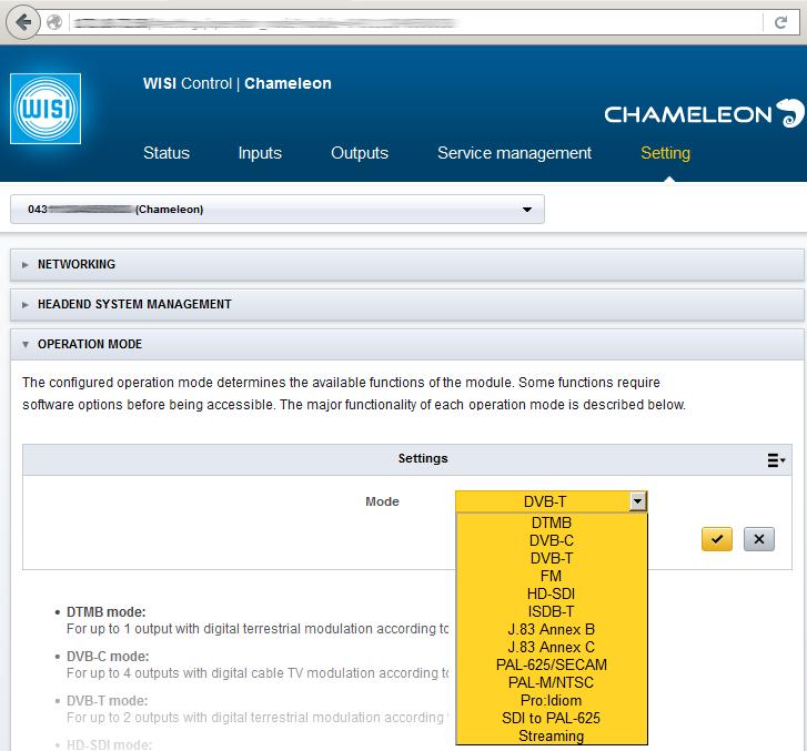
18 Selecting operation mode The operation mode must in most cases be explicitly selected, since it configures the Chameleon's basic behaviour. When the Chameleon is used for the first time, the operation mode is the first thing that should be configured. The Chameleon has 13 different operation modes: Name Type and number of outputs Number of ASI in/out Number of IPTV inputs Number of IPTV outputs DTMB 1 digital chinese cable TV modulator DVB-C 4 digital cable TV modulators DVB-T 2 digital terrestrial modulators FM 8 analog FM radio modulators HD-SDI 1 digital serial HD video ISDB-T 1 digital japanese/south american terrestrial modulator J.83 Annex B 4 digital american cable TV modulators J.83 Annex C 4 digital japanese cable TV modulators PAL-625/SECAM 2 analog 625 lines PAL/SECAM TV modulators PAL-M/NTSC 1 analog 525 lines PAL/NTSC TV modulator Pro:Idiom 8 services Pro:Idiom scrambling with ASI and IPTV in and out. SDI to PAL analog 625 lines PAL TV modulators Streaming High density IPTV with or without FEC in and out The number of modulators and IPTV inputs and outputs is dependant on software options. IPTV in can handle 850 Mbit/s in all operation modes. IPTV out can handle 850 Mbit/s in all operation modes. The total bit rate that the Chameleon can handle is 1200 Mbit/s. The total bit rate is the sum of all bit rates in to the Chameleon. Any scrambling and/or descrambling adds to the total bit rate. FEC will also reduce the total bit rate. The total bit rate affects the Chameleon's IPTV input dejittering capability. FEC on IPTV out is only supported in Streaming operation mode. All operation modes listed above, except for HD-SDI, Pro:idiom and SDI to PAL-625, configure what kind of modulation the Chameleon can output on the RF connector. The last operation mode, Streaming, configures the Chameleon to have maximum performance on the IPTV streaming output, and therefore it does not have a modulator at all. Click on Operation Mode in the Settings view to change the operation mode, see screenshot below. Click on the context menu to the right of Settings and then select Edit. Select the desired operation mode from the drop-down list, and apply the setting.
19 19

20 Adding and configuring inputs Chameleon has three types of inputs: 2 digital TV tuners. 2 BNC connectors capable of ASI, SDI and HD-SDI. 1 IPTV. The tuner inputs are always accessible, independent on operation mode or configuration. The capabilities on the tuner input depend on which tuner module the Chameleon is equipped with. Which tuner the Chameleon is equipped with can be seen in the Status view. The BNC connectors can be configured as inputs or outputs. When configured as inputs, they can support ASI in all operation modes except Pro:Idiom, HD-SDI and SDI to PAL-625. ASI is not supported at all in operation mode Pro:Idiom, and only one ASI input is supported for operation mode HD-SDI. For operation mode SDI to PAL-625, the BNC connectors can only be used for SDI. In operation mode PAL-625/SECAM and PAL-M/NTSC, the BNC connectors can be configured independently for ASI or SDI Adding an input To create a new input, click ADD NEW INPUT in the Inputs view. Select what type of input to create, ASI, IPTV or TUNER. SDI as input can only be chosen in operation mode SDI to PAL-625. Give the input a name. After any input specific settings have been chosen, click the settings. to save After saving, the status of the configured input is shown. If for example an input is not supported in the current operation mode or an input configuration is wrong, there will be displayed a notification with an error message. The web UI is self-explanatory on most settings, but some will be further explained in the following sections Status values The Chameleon displays status values for each input. The status values shown depend on the type of input and the type of input signal. The Bitrate status value behaves differently depending on the type of input. For all inputs, except IPTV with Bitrate mode VBR, the status value is the average input bit rate of the transport stream, including NULL packets. For IPTV with Bitrate mode VBR, the status value is a snapshot of the current transport stream bit rate (including NULL packets) between PCR values. The snapshot is updated in a few seconds interval.

21 Tuner input Currently the Chameleon has been shipped with four different RF tuner modules: tuner045 supports DVB-S and DVB-S2. tuner047 supports DVB-S, DVB-S2, DVB-C and DVB-T. tuner048 supports DVB-S, DVB-S2, DVB-C, DVB-T and DVB-T2. tuner067 supports DVB-S, DVB-S2, DVB-C, DVB-T, DVB-T2, J.83 Annex B, J.83 Annex C and ISDB-T. The available tuner input types will depend on the hardware. To see which RF tuner module the Chameleon is equipped with, look in the Status view. Starting with software 3.0, all RF tuner inputs are included. No software options are needed for the RF tuner inputs Frequency The input frequency can for all tuner inputs, except DVB-S and DVB-S2, be set using a frequency table and the channel number. The Chameleon supports two channel tables, CCIR and OIRT. For DVB-S and DVB-S2, or when not using a channel table, the frequency can be set manually. For DVB-S and DVB-S2 the input frequency is the same as the satellite transponder's frequency. This means that the Chameleon's LO frequency must match the LNBs. For LNB type Universal, the LO frequencies are and 9750 MHz. LNB type Fixed and C-band is the same thing and requires that the LO frequency is set manually External satellite switch The Chameleon can generate 13/18 V and 22 khz. It also has support for DiSEqC. If the LNB type is Universal, Switch type should be set to None or DiSEqC switch. The LNB power cannot be disabled when LNB type is Universal. If the LNB type is Fixed or C-band, Switch type should be set to None, DiSEqC switch, Multiswitch or DiSEqC multiswitch. Switch type None means that no LNB signalling will be sent from the Chameleon to the LNB. The exception is for LNB type Universal, which will transmit the 13/18 V and 22 khz, depending on transponder frequency and polarisation. For LNB type Fixed and C-band, Polarisation has no meaning. It is shown only for information on the polarisation that is intended to be used. Switch type DiSEqC switch means that the Chameleon will send DiSEqC commands to access 1 of 4 ports on a DiSEqC compatible switch. The DiSEqC commands will be repeated 3 times, so cascaded DiSEqC switches should work well. Besides the DiSEqC commands, the Chameleon will also send the SA/SB command to support Tone Burst DiSEqC switches. Use DiSEqC port 1 or 3 to access the SA path, and port 2 or 4 to access the SB path. The simplest switches that only listen to the presence/absence of the 22 khz tone will also work if Switch type is set to DiSEqC switch. Switch type Multiswitch means that the Chameleon will output 13/18 V and 22 khz, depending on the Source setting.
22 22 Switch type DiSEqC multiswitch means that the Chameleon will send DiSEqC commands to access 1 of 4 ports on a DiSEqC compatible switch, and also output 13/18 V and 22 khz depending on the Source setting DVB-T2 PLP When receiving DVB-T2, which PLP to receive can be selected. PLP should be set to Automatic for DVB-T2 signals that only have one PLP. For DVB-T2 signals that have multiple PLPs, PLP should be set to Manual and PLP ID should be set to the ID of the PLP to receive ISDB-T The ISDB-T tuner input may cause excessive PCR jitter when it is sent to a digital output.

23 ASI input The Chameleon supports ASI in with both 188 byte and 204 byte packets. At least one of the software options GNASI or GNDASI is required. The ASI input auto-detects the format, so no settings other than Physical port are needed. Any error correction that is received in the 204 byte packet format is ignored. ASI and SDI share the two BNC connectors, and they are controlled by software configuration. See section 6.4 for availability of ASI in different operation modes.

24 IPTV input The Chameleon can receive IPTV containing MPEG transport streams, both SPTS and MPTS. Software option GNSTR is required for IPTV input and GNSTREC is required for FEC support. Before an IPTV input can be configured, a streaming interface must be configured. See section on how to do this. We consider the input MPEG transport stream an MPTS if it contains more than one packet stream (PID) with a PCR. Usually, this means that the stream contains more than one service. The input MPEG transport stream is considered an SPTS if it only contains one packet stream (PID) with a PCR, and this usually implies that it only contains one service. The IPTV input can be used for internal streaming in a GN50 without the GNSTR software option. For this to work, the Chameleon must use software or newer and the GT11 must use software 2.3 or newer Introduction to IPTV IPTV is the name for delivering TV signals over the Ethernet, mainly using the Internet but also on local networks. The Chameleon is only capable of handling MPEG transport streams, so this manual assumes that the IPTV signal only contains MPEG transport streams. The MPEG transport stream is encapsulated in UDP or UDP+RTP IP packets. Using UDP (without RTP) puts higher demands on the network between the client and the server. When encapsulated in a UDP IP packet we call it UDP, and when encapsulated in a UDP+RTP IP packet we call it RTP. When FEC is added to the UDP+RTP IP packet we call it RTP+FEC. The IP packets can then be sent as Unicast or Multicast. Unicast is a one-to-one connection, while Multicast is a one-to-any connection between the server and the client. In an IPTV stream there are two kinds of jitter that need to be dealt with: MPEG transport stream jitter (measured as PCR jitter) and IP packet jitter. It is important to make a distinction between these two kinds of jitter, since they are compensated for in different ways in the Chameleon Protocol Choose Protocol to match the IPTV stream Routing scheme Choose Routing scheme to match the IPTV stream that is received. Unicast only requires that the UDP port is configured to match the setting for the IPTV source. The IP address will be the same as the IP address of the streaming interface that has been configured for the IPTV stream. Multicast requires that the destination IP address in the IP packet and the UDP port is configured, so that it matches the settings for the IPTV source. Allowed multicast IP address is in the range to
25 25 Source address can be used for differentiating between multiple incoming IPTV streams with the same multicast address. If this differentiation is not needed, leave Source address at the default Please note that IGMP v3 has to be configured on the Chameleon's streaming interface if IGMP is used for source specific multicast (SSM) and Source address has been changed from the default Bitrate mode The Chameleon has three different Bitrate modes to handle different kinds of IPTV streams; CBR, Manual bitrate and VBR. It is important to understand which one to use for the IPTV input. CBR (Constant Bit Rate) is used for MPTS and SPTS. It requires that the MPEG transport stream has a constant bit rate. VBR (Variable Bit Rate) is used for SPTS. The MPEG transport stream can have variable or constant bit rate, but must only contain a single packet stream (PID) with a PCR. Manual bitrate is meant for IPTV streams that do not contain audio nor video. For example OTA, EPG. The MPEG transport stream can be CBR or VBR. Support for VBR is according to SMPTE , but without FEC. To handle the IP packet jitter, all Bitrate modes require that Max expected jitter is configured. The Max expected jitter configuration is located under Advanced settings, since its default value should work for most IPTV streams. For Bitrate mode VBR, the Max expected jitter setting must not be lower than neither of the maximum IP packet jitter nor the MPEG transport stream's PCR repetition interval. Bitrate mode VBR also requires a Max expected bitrate configuration. The Max expected bitrate configuration is located under Advanced settings, since its default value should work for most IPTV streams. If the maximum bitrate for the IPTV input is known, the Chameleon resource usage can be optimized using the Max expected bitrate configuration. Using high values for Max expected jitter and/or Max expected bitrate means a more robust IPTV input with regards to IP packet jitter, and for VBR more robustness against long PCR repetition intervals. The downside is that the resource utilization in the Chameleon will increase and that the input to output delay in the Chameleon will increase. The resource utilization in the Chameleon can be monitored by clicking the Resource utilization tab at the top right in the Status view. Look at Utilization under TS processing. For Bitrate mode Manual bitrate, Manual bitrate must be configured. The Manual bitrate is the bit rate that the Chameleon uses to internally send the IPTV input stream forward. Its usage is best illustrated with an example; Manual bitrate is set to 10 Mbit/s and the stream is connected to an existing DVB-C output. The DVB-C output will then peak with 10 Mbit/s extra if the IPTV input stream bursts 10 Mbit during 100 ms. To decrease this peak in bit rate, Manual bitrate can be set to for example 1 Mbit/s. The DVB-C output will then instead peak with 1 Mbit/s extra during one second. However, this means that Expected jitter must be set to at least one second, otherwise data will be lost on the input IGMP IGMP is used to join multicast streams that are otherwise filtered out by multicast filtering network equipment. The Chameleon supports IGMP v2 and v Adding multiple IPTV inputs It is easy to add many IPTV inputs. Just set Create mode to Multiple, define Number of inputs to create and set Property to increment.
26 IPTV input redundancy The IPTV input redundancy's main purpose is to handle the case where an IPTV stream is sent over multiple networks. If some of the networks fail, the Chameleon will switch to a network that has not failed. The IPTV input redundancy can be used for other redundancy cases, but it is important to understand that the IPTV input redundancy does not offer a complete redundancy solution, it only handles switching between different IPTV input sources. The IPTV sources must use the same Protocol (UDP, RTP, RTP+FEC) and Bitrate mode (CBR, Manual bitrate, VBR), and the PIDs in the MPEG transport streams must also match. The criteria for a failing IPTV input is that the MPEG transport stream bit rate is below a certain threshold. Bitrate threshold can be set to 0 to detect a failure on IP level (like a broken/disconnected IP cable). For example, to detect a missing service in the MPEG transport stream, the Bitrate threshold can be set to a few kbit/s. The IPTV input redundancy can only be configured after the IPTV input has been created, and this is done by expanding Alternative configurations and selecting Add configuration from the context menu. The redundancy must also be enabled by setting Redundancy mode under the IPTV input to On. The Priority setting is used to set the priority in case more than one alternative configuration is needed. When an alternative configuration exists, it will be shown in the Active configuration drop-down list under IPTV input. When the redundancy is triggered, the alternative configuration with the lowest Priority number will be the first used. If the used alternative configuration also fails, the next alternative configuration will be used. If there is no next alternative configuration, the primary configuration will be used. If an alternative configuration is active and the primary source starts to operate normally, there will be no automatic switch back. An alternative configuration can be manually configured using the Active configuration setting. Besides Bitrate threshold, Linger time and Latency time must be configured. Linger time is the time an IPTV input will be used after its bit rate has fallen below the Bitrate threshold. If the bit rate goes above Bitrate threshold during Linger time, no switch-over will occur. If Linger time is set to 0, the IPTV input will immediately use its alternative configuration. Latency time is the time the alternative configuration is tried out for a bit rate. If there is no bit rate within the Latency time, the next alternative configuration is tried. Latency time is used to allow Ethernet switches time to get the IGMP message from the Chameleon module and forward the stream. There is no automatic fall-back, but if an alternative configuration fails, there will be a new search for available configurations, starting with the primary configuration.
27 FEC FEC is used to recover IP packets that are lost in the network. The FEC settings make it possible to configure the amount of packet loss that can be restored. IPTV input with FEC requires software option GNSTREC. The Chameleon supports IPTV streams with FEC according to SMPTE and In short, this means that the Chameleon supports FEC for CBR. The maximum IPTV input bit rate, 850 Mbit/s for Chameleon, is reduced by the amount of redundancy that the FEC uses. This depends on the configured FEC dimension, but can mean that up to 50% of the output bit rate is used for redundancy. The choice of FEC dimension also affects the maximum bit rate throughput in the Chameleon. The throughput can be reduced by up to a factor 2.

 is supported by the Chameleon in operation mode SDI to PAL-625.")
28 SDI input The Chameleon can modulate up to two analog TV signals in 625 lines PAL format from SDI in, using the SDI to PAL-625 operation mode. At least one of the software options GNSSDMOD or GNDSDMOD is required. ASI is not available in operation mode SDI to PAL-625. The SDI input video must be in 576i50 format (720x576 interlaced, field rate 50 Hz) and the audio must be two channels, uncompressed, with sampling rate 32, 44.1 or 48 khz. Only open subtitling (burnt-in) is supported by the Chameleon in operation mode SDI to PAL-625. No processing is performed on the video or audio, so the Analog TV modulator output will be the same as the input on SDI. The SDI input auto-detects the format so no settings other than Physical port are needed. After an SDI input has been created, the detected input video format is shown under STATUS. See screenshot to the right. To use the SDI input, create an Analog TV modulator output and select the BNC connector as Input. See section for information on how an Analog TV modulator is configured.

29 Adding and configuring outputs The Chameleon has many types of outputs. The outputs that are available depend on the software options and the current operation mode. See section 6.4 for available operation modes and which of these have ASI as output Output buffer All outputs that consist of an MPEG transport stream in a Chameleon have an output buffer. This buffer is used to handle intermittent peaks in the MPEG transport stream bit rate. Intermittent peaks in the data can cause problems when multiple data streams are combined. This is best illustrated with an example: Suppose that a DVB-C output is capable of 38 Mbit/s. If five services whose average bit rates are 6 Mbit/s and whose peak bit rates are 9 Mbit/s are added to the DVB-C output, these will have an average bit rate of 5x6 = 30 Mbit/s, and a maximum peak bit rate of 5x9 = 45 Mbit/s. The Chameleon's output buffer will average out the 45 Mbit/s so it fits within the 38 Mbit/s. How large peaks in bit rate the Chameleon can handle is configured using Buffer size. Buffer size is located under Advanced settings for each output. Buffer size should normally be left at its default value. The output buffers occupy limited resources in the Chameleon. The resource utilization in the Chameleon can be monitored by clicking the Resource utilization tab at the top right in the Status view. Look at Utilization under TS processing Adding an output To create a new output, click ADD NEW OUTPUT in the Outputs view. Select what type of output to create. Available outputs depend on the operation mode. Configure the name of the output. After any output specific settings have been chosen, click the yellow tick save the configuration. to After saving, the status of the configured output is shown. If for example too many outputs are configured, or an output that is not supported in the current operation mode, there will be a notification with an error message displayed.
30 RF outputs, common settings and limitations The output frequency configuration is the same for all RF outputs. Either choose the channel table and channel, or choose the frequency. Supported frequency tables are CCIR, OIRT, OI and EIA. The RF output on the Chameleon has limitations that are common for all types of RF outputs. The Chameleon's RF output has a bandwidth of about 40 MHz. Therefore all RF outputs from a Chameleon must be configured so that they fit within 40 MHz. The Chameleon's RF output amplitude depends on the type of RF output and the number of RF outputs. For each added output, the RF output level for each output is decreased by 3 db.the amplitude is the same for all RF outputs of the same type. The tolerance for the output level is typically ±1 db. The Chameleon's RF output performance is guaranteed to be within specification between 50 and 860 MHz. It is possible to configure the output frequency outside of this range, but the spurious suppression and output amplitude will then not be within specification. The broadband noise and the fixed spuriouses out from the Chameleon's RF output limits the number of Chameleons that can be combined together without using filters.
31 RF output PAL-625/SECAM & PAL-M/NTSC The Chameleon has support for almost all worldwide analog TV video modulation types. To use analog TV with 625 lines PAL or SECAM modulated video, the PAL-625/SECAM operation mode is selected. To use analog TV with PAL-M or NTSC modulated video, the PAL-M/NTSC operation mode is selected. To use analog TV with 625 lines PAL modulated video from an SDI input, the SDI to PAL-625 operation mode is selected. The Chameleon has support for almost all worldwide analog TV audio modulation types, but they are only available for the relevant video modulation types. For PAL-625/SECAM, it is possible to choose between NICAM and A2. For PAL-M/NTSC only MTS+SAP (also known as BTSC) is available. Except for operation mode SDI to PAL-625, the Analog TV modulator takes its input from an MPEG transport stream. How the audio and video from the MPEG transport stream is decoded and how the image is scaled is described in section The Chameleon can extract several types of subtitles (or captionings, as subtitling for hearing impaired is called in north America and Canada) from the MPEG transport stream and insert them into the Analog TV modulator: Bitmapped DVB subtitling that is sent in a packet stream (PID) can be output on the Analog TV modulator as open subtitling (burnt-in). Teletext DVB subtitling that is sent in a packet stream (PID) can be output on the Analog TV modulator as teletext or open subtitling (burnt-in). Teletext is only possible in operation mode PAL-625/SECAM. CEA-608 closed captioning that is embedded in a video stream's user data can be output on the Analog TV modulator as CEA-608 closed captioning. This is only available in operation mode PAL-M/NTSC. SCTE-27 subtitling that is sent in a packet stream (PID) can be output on the Analog TV modulator as open subtitling (burnt-in). The Chameleon can also extract teletext from the MPEG transport stream and insert it into the Analog TV modulator. In fact, teletext DVB subtitling is just a part of the entire teletext. See section for information on how to handle incoming teletext and section for information on how to handle incoming subtitling. Normally, only the TV system and the Audio system need to be configured, but to aid in special circumstances the Chameleon's modulation parameters can be tweaked. At least one of the software options GNVMOD or GNDVMOD is required to use the Analog TV modulator. In case decoding of Dolby Digital (AC-3) is needed, at least one GNDOL software option is required. The exception is when SDI is used as input to the Analog TV modulator, then at least one of the software options GNSSDMOD or GNDSDMOD is required. To use MTS and/or SAP sound, at least one of the software options GNBTS or GNDBTS is required.

32 Carrier level The output level for one Analog TV modulator is between 84 dbµv and 111 dbµv, configured in 1 db steps. The level is for the unmodulated video carrier. If two Analog TV modulators are used, the possible output level will instead be 81 dbµv to 108 dbµv WSS subtitle configuration The Chameleon can send information to the TV receivers regarding the placement of open subtitles (burnt-in) using WSS according to ETSI EN This is not available for TV systems PAL-M, NTSC-M or PAL-Nc, or operation mode SDI to PAL-625. Possible options for the WSS signalling are: None. Please read the ETSI standard for further information. Auto means that the Chameleon calculates the appropriate WSS signalling based on the decoded input video and the placement of any subtitles. It is therefore affected by the choice in WSS aspect ratio, see section In picture. Please read the ETSI standard for further information. Out of picture. Please read the ETSI standard for further information TV system The TV system configuration defines almost all properties of the analog TV signal, and should be chosen to match the country/region in which the Chameleon is used. Some of the settings can be overridden using the Advanced menu. For operation mode PAL-M/NTSC choose between PAL M NTSC M For operation mode PAL-625/SECAM choose between PAL B/G PAL B/H PAL D/K PAL I PAL Nc SECAM B/G
33 33 SECAM D/K For operation mode SDI to PAL-625 choose between PAL B/G PAL B/H PAL D/K PAL I PAL Nc Audio system The Chameleon supports several types of audio signals on the Analog TV modulator output. Besides the mono sound modulation, it supports stereo and/or bi-lingual sound modulation using A2, MTS/MTS+SAP or NICAM. See section for information on how input audio is decoded, and for information on how stereo and surround sound on the input is handled. For operation mode PAL-M/NTSC choose between MTS (sometimes referred to as BTSC), adds an MTS modulated stereo difference signal. The modulated mono signal is the left and right audio channels mixed together, and the MTS modulated stereo difference signal is the difference between the left and right audio channels. MTS+SAP is the same as MTS, but it adds one more mono audio channel. This additional audio channel is meant for bi-lingual support. The Chameleon will always mix the two audio input channels that are used for SAP. If the two input audio channels for example contain different languages, make sure that Stereo mode is set to Dual left or Dual right. See section Mono disables any stereo audio modulation. The mono sound is the left and right audio channels mixed together. For operation mode PAL-625/SECAM and operation mode SDI to PAL-625 choose between A2 Stereo adds an A2 modulated stereo signal. The modulated mono signal is the left and right audio channels mixed together. For TV systems PAL D/K and SECAM D/K the frequency of the A2 signal (sometimes called A2*) must be configured. A2+ is not supported by the Chameleon. NICAM adds a NICAM modulated stereo signal. The modulated mono signal is the left and right audio channels mixed together. The frequency, amplitude and roll-off for the NICAM signal are automatically configured by the chosen TV system. Mono disables any stereo audio modulation. The mono sound is the left and right audio channels mixed together. A2 Dual Mono and NICAM Dual Mono are the same as A2 Stereo and NICAM above, but instead of stereo they output dual mono audio. This is mainly meant for bi-lingual support. The modulated mono sound is the left audio channel. If the two audio channels that are to be used come in the same audio stream, select Selected decoder in the Dual audio source drop-down box. Normally, Stereo mode is configured to Stereo, see section If the two audio channels come in separate audio streams, Both decoders must be selected in the Dual audio source drop-down box. Normally, Stereo mode is configured to Dual mono, see section Be aware that the Both decoders choice means that one Analog TV modulator output uses both the decoders in the Chameleon. It is possible to add a second Analog TV modulator output, but the audio will be the same as for the first Analog TV modulator output. Please note that for operation mode SDI to PAL-625, the first audio channel in the SDI is always sent on the first mono audio channel on the Analog TV modulator output, and the second audio channel in the SDI is always sent on the second mono audio channel on the Analog TV modulator output.
34 Advanced setting OSD Test pattern The Chameleon displays vertical colour bars instead of video from the decoder on the Analog TV modulator output when OSD Test pattern is enabled. A test tone will also be output. This is not available for operation mode SDI to PAL-625. Please note that this setting will also affect any SDI and HD-SDI output Advanced setting WSS configuration The WSS configuration setting allows the Chameleon to send information to the TV receivers regarding the size and placement of the video using WSS according to ETSI EN This is not available for TV systems PAL-M, NTSC-M or PAL-Nc, or operation mode SDI to PAL-625. Auto means that the Chameleon calculates the appropriate WSS signalling based on the decoded input video. The video decoding is described in section Off means that WSS will be entirely disabled. Forced 4:3 means that WSS will be signalled as 4:3 Full format, regardless of the format of the decoded input video. Forced 14:9 means that WSS will be signalled as 14:9 Letterbox, centered format, regardless of the format of the decoded input video. Forced 16:9 means that WSS will be signalled as 16:9 Letterbox, centered format, regardless of the format of the decoded input video Advanced setting Stereo mode The Analog TV modulator output supports up to two channels of audio. However, the digital audio in to the Chameleon can contain up to eight channels of audio. The Stereo mode configuration is used to configure the way the input audio is handled on the output. For Stereo, Dual mono, Dual left and Dual right, any input audio with more than two channels will be downmixed into two channels. Stereo. Left and right input audio channel will be sent out on both left and right audio channels. Dual mono. Left and right input audio channels are mixed to a mono channel that is output on both left and right audio channels. Dual left. Left input audio channel will be sent out on both left and right audio channels. Dual right. Right input audio channel will be sent out on both left and right audio channels. Dolby Pro Logic II. If the input audio has more than two channels these will be downmixed into two channels using the Dolby Pro Logic II algorithm. Please note that this setting will also affect any SDI and HD-SDI output Advanced setting VPS signalling The Chameleon has support for VPS (Video Program System) in operation mode PAL-625/SECAM, and this is configured using VPS signalling. Off disables the VPS signalling. From Teletext sets the source for the VPS signalling data to teletext. From EIT sets the source for the VPS signalling data to EIT.
35 Advanced setting Closed captioning The Chameleon has support for closed captioning according to CEA-608 in operation mode PAL-M/NTSC, and this is configured using Closed captioning. The Chameleon will send the received CEA-608 captioning transparently. See section for more information about CEA-608 captioning. On enables closed captioning. For this to work, the video stream must contain closed captioning data. Off disables closed captioning Advanced setting Carrier wave When setting Carrier wave to On, an RF carrier is output instead of the modulated video and audio. This can be used for measuring the amplitude of the output with a simple spectrum analyzer Advanced setting Video bandwidth The Video bandwidth configuration is used to change the default bandwidth of the video filter. All filter bandwidths are not available for all TV systems. It is advised not to change this setting, since the result is not guaranteed to have the expected effect. 4.2 MHz sets the filter bandwidth to 4.2 MHz. 5 MHz sets the filter bandwidth to 5.0 MHz. 5.5 MHz sets the filter bandwidth to 5.5 MHz. 6 MHz sets the filter bandwidth to 6.0 MHz Advanced setting Video carrier modulation depth The Video carrier modulation depth configuration is used to change the default video modulation depth. It is advised not to change this setting, since the result is not guaranteed to have the expected effect. The modulation depth can be set to a value between 80 and 90% Advanced setting Video group delay pre-correction The Video group delay pre-correction configuration is used to change the default phase behaviour of the video filter. It is advised not to change this setting, since the result is not guaranteed to have the expected effect. None disables the group delay pre-correction. B/G general sets the group delay pre-correction to suit TV systems B/G/H/I. D/K GOST sets the group delay pre-correction to suit TV systems D/K. M FCC sets the group delay pre-correction to suit TV systems M/Nc Advanced setting Test lines The Chameleon can insert test lines into the Analog TV modulator output, and this is configured using Test lines. Test lines are added on lines 17, 18, 330 and 331 for all TV systems except system M. For system M the test lines are located on lines 17, 18, 280 and 281. Test lines can be useful for measuring the Analog TV modulator performance. On enables test lines. Off disables test lines Advanced setting Identification The Chameleon supports TV system SECAM with and without vertical identification and this is configured using Identification. The Identification setting is only available for TV system SECAM. Horizontal means that only horizontal colour sync is generated. Also known as SECAM H.
36 36 Horizontal+Vertical means that both horizontal and vertical colour sync is generated. Also known as SECAM V Advanced setting Audio gain The Audio gain configuration is used to change the audio level in the range -12 to +12 db. This can be used to compensate for media that broadcast a too low or too high audio level. Please use this setting with care, since a too high audio level can cause unwanted side effects, like audible distortion and spuriouses on the Analog TV modulator output. This setting will affect the mono and stereo audio level Advanced setting Audio subcarrier level The Audio subcarrier level configuration is used to change the default carrier level for the mono sound and the MTS+SAP modulated signal in the range -30 dbc to -10 dbc. The Audio subcarrier level is only available for operation mode PAL-M/NTSC. Please use this setting with care, since a too high audio carrier level can cause unwanted side effects, like spuriouses on the Analog TV modulator output Advanced setting Mono subcarrier level The Mono subcarrier level configuration is used to change the default carrier level for the mono sound modulated signal in the range -30 dbc to -10 dbc. The Mono subcarrier level is only available in operation mode PAL-625/SECAM and SDI to PAL-625. Please use this setting with care, since a too high audio carrier level can cause unwanted side effects, like spuriouses on the Analog TV modulator output Advanced setting Stereo subcarrier level The Stereo subcarrier level configuration is used to change the default carrier level for the NICAM and A2 modulated signals in the range -30 dbc to -13 dbc. The Stereo subcarrier level is only available in operation mode PAL-625/SECAM and SDI to PAL-625, and NICAM or A2 must be configured as Audio system. Please use this setting with care, since a too high audio carrier level can cause unwanted side effects, like spuriouses on the Analog TV modulator output TV/Radio OSD The Chameleon has support for adding different types of OSD (On Screen Display) on the Analog TV modulator outputs and on the SDI and HD-SDI outputs (not available for operation mode SDI to PAL-625): The service name to a radio service. The displayed text is always the service name. The size, font and position of the text is fixed, but the colour, background and transparency can be adjusted. A configurable text to a video service. The size and font of the text is fixed but the text string, colour, background, transparency, position and movement can be adjusted. The WISI logo to a video service. An uploaded image in PNG format to a video service. See section 6.15 for information on how to upload an image. The PNG image's aspect ratio must match the outputs since the image is stretched to fit the output video resolution. Transparency in PNG files is not handled. It is also possible to add an OSD when the audio or video has failed to decode, using the Decoder error display drop-down menu. TV OSD does not work in conjunction with subtitling. If OSD is enabed, any DVB teletext or SCTE subtitling will not be displayed. For DVB subtitling, OSD will work when it is placed apart from the DVB subtitling display area. Please note that this setting will also affect any SDI and HD-SDI output.

37 RF output DTMB The Chameleon supports a subset of the DTMB modulation standard (Chinese national standard GB ). The software option GNDMOD is required. DTMB is meant for digital terrestrial TV distribution, mainly in China. The following parts of the standard are not supported: LDPC code rate 0.4. Constellation 32-QAM and 4-QAM-NR. Non-COFDM mode (single carrier). 0 length interleaving (convolutional interleaver off). The output level for one DTMB modulator is between 74 dbµv and 101 dbµv, configured in 1 db steps. The maximum MPEG transport stream throughput on DTMB depends on the code rate, the header length and the constellation: bit rate (Mbit/s) = 7.56 CR m, where CR is 752 for code rate 0.6, for PN code rate 0.8, PN is the header length (420, 595 or 945) and m is 2 for 4-QAM, 4 for 16-QAM and 6 for 64- QAM. Selecting a longer Header length allows for higher tolerance to distant echoes, but reduces the useful bit rate. Selecting a long (high) Interleaving length increases the robustness against impulsive noise contributed by the terrain between the transmitter and the receiver. The disadvantage with a long time interleave length is that it will take longer for a receiver to lock on the signal. The burst protection time and the latency is three times as high for M=720 than for M=240. Selecting Code rate 0.6 gives, compared to Code rate 0.8, a larger margin to noise contributed by the terrain between the transmitter and the receiver, but reduces the useful bit rate. Selecting a higher Constellation increases the useful bit rate, but gives less margin for noise contributed by the terrain between the sender and the receiver.

38 RF output DVB-C and J.83 Annex C The Chameleon has full support for the DVB-C and J.83 Annex C modulation standards (ETSI EN V1.2.1, ITU-T Recommendation J.83). At least one of the software options GNCMOD, GNDCMOD, GNTCMOD or GNQCMOD is required. DVB-C and J.83 Annex C are meant for digital cable TV distribution, mainly in Europe and Japan. Symbol rates in the range 3825 to 4687 kbaud are not supported for DVB-C and J.83 Annex C. The Chameleon can generate symbol rates for DVB-C and J.83 Annex C as high as MBaud. To fit the DVB-C within an 8 MHz channel, its symbol rate should be kept below 6.95 MBaud, and to fit the J.83 Annex C within a 6 MHz channel, it should be kept below 5.30 MBaud. The output level for one DVB-C/J.83 Annex C modulator is between 78 dbµv and 105 dbµv, configured in 1 db steps. If two DVB-C/J.83 Annex C modulators are used, the possible output level will instead be 75 dbµv to 102 dbµv. For three DVB-C/J.83 Annex C modulators it becomes 72 dbµv to 99 dbµv, and for four it becomes 69 dbµv to 96 dbµv. The maximum MPEG transport stream throughput on DVB-C and J.83 Annex C depends on the symbol rate and the constellation: bit rate (Mbit/s) = SR 188 m, where SR is the symbol rate in MBaud and m is 4 for 16-QAM, 5 for QAM, 6 for 64-QAM, 7 for 128-QAM and 8 for 256-QAM. The occupied analog bandwidth is SR x 1.15 for DVB-C and SR x 1.13 for J.83 Annex C. Selecting a higher Constellation increases the useful bit rate, but gives less margin for noise contributed by the cable network. QAM spectrum should normally be configured to Normal. Symbol rate is normally chosen so that the analog bandwidth of the signal just fits within a channel.
39 RF output J.83 Annex B The Chameleon has full support for the J.83 Annex B modulation standard (ITU-T Recommendation J.83). At least one of the software options GNCMOD, GNDCMOD, GNTCMOD or GNQCMOD is required. J.83 Annex B is meant for digital cable TV distribution, mainly in America. The output level for one J.83 Annex B modulator is between 78 dbµv and 105 dbµv, configured in 1 db steps. If two J.83 Annex B modulators are used, the possible output level will instead be 75 dbµv to 102 dbµv. For three J.83 Annex B modulators it becomes 72 dbµv to 99 dbµv, and for four it becomes 69 dbµv to 96 dbµv. The Chameleon has full support for J.83 Annex B. The symbol rate is fixed to MBaud for 64-QAM, and MBaud for 256-QAM, and the occupied analog bandwidth is 6 MHz. This translates to a maximum MPEG transport stream bit rate of (or more exactly ) Mbit/s for 64-QAM and (or more exactly ) Mbit/s for 256-QAM Selecting a higher Constellation increases the useful bit rate, but gives less margin for noise contributed by the cable network. Selecting a long (high) Interleaving length increases the robustness against impulsive noise in the cable network. The disadvantage with a long time interleave length is that it will take longer for a receiver to lock on the signal. The burst protection time and the latency is almost proportional to I 2 xj. QAM spectrum should normally be configured to Normal.

40 RF output DVB-T The Chameleon has full support for the DVB-T modulation standard (ETSI EN V1.6.1) with the exception of hierarchical modulation. At least one of the software options GNTMOD, GNDTMOD is required. DVB-T is meant for digital terrestrial TV distribution, mainly in Europe. The output level for one DVB-T modulator is between 75 dbµv and 102 dbµv, configured in 1 db steps. If two DVB-T modulators are used, the possible output level will instead be 72 dbµv to 99 dbµv. The maximum MPEG transport stream throughput on DVB-T depends on the RF bandwidth, the constellation, the code rate and the guard interval: bit rate (Mbit/s) = BW m CR 1, where BW is 5 for 5 MHz, 6 for 6 MHz, GI 7 for 7 MHz and 8 for 8 Mhz RF bandwidth, m is 2 for QPSK, 4 for 16-QAM and 6 for 64-QAM, CR is the code rate (1/2, 2/3, 3/4, 5/6, 7/8) and GI is the guard interval (1/4, 1/8, 1/16, 1/32). The equation is for nonhierarchical mode. Bandwidth is chosen to fit within a channel. Selecting a low Code rate, (1/2 for example), gives a larger margin to noise contributed by the terrain between the transmitter and the receiver, but reduces the useful bit rate. Selecting a high Guard interval (1/4 for example) allows for higher tolerance to distant echoes, but reduces the useful bit rate. Carrier mode 8k has the advantage over 2k in that it can be used for larger single frequency networks and with longer distances between transmitters. Carrier mode 2k has the advantage over 8k in that it has better doppler performance, allowing for reception at higher motional speeds. Selecting a higher Constellation increases the useful bit rate, but gives less margin for noise contributed by the terrain between the sender and the receiver.
 or MPEG-2 AAC, with up to two channels, and with a sample rate of 48 khz.")
41 RF output FM The Chameleon has support for stereo FM radio with RDS. The input audio data must be MPEG-1 (Layer I, II or III) or MPEG-2 AAC, with up to two channels, and with a sample rate of 48 khz. MPEG-2 Audio (ISO/IEC ) is supported since it is backwards compatible with MPEG-1. At least one of the software options GNDFM or GNOCTFM is required. The output level is always between 70 dbµv and 92 dbµv for each FM radio modulator, configured in 1 db steps. The output frequency must be within 87.5 and 108 MHz. The FM radio output will contain the mono (L+R audio channel) audio, stereo pilot tone, stereo (L-R audio channel) audio and the RDS signal. The audio pre-emphasis is fixed at 50 us. The FM radio output's frequency deviation is approximately 75 khz when the input signal is a sine wave at 1 khz with the amplitude -6 dbfs. See section for information on how to select input audio for the FM radio output. Before configuring the input audio, the service that contains the audio must be added to the FM output. This is accomplished using the service's context menu in the Input view in the Service management view. The Chameleon can extract the RDS data fields PI, PS, PTY and CT from the UECP that sometimes is sent in the MPEG transport streams MPEG audio. The Chameleon can add the RDS data fields, PI, PS, PTY and CT to the FM modulator output. The following is a simplified description of what they mean: PI is a unique code that is used to identify the station. PS is used to identify the station name. It can be up to eight characters long. PTY is used to signal the typ of material that is broadcasted. It can be a number from 0 to 31, where for example 10 is pop music in Europe. CT is the date and time. PI, PS and PTY RDS data fields on the FM modulator output can be set to From incoming audio (UECP) or they can be set manually. The CT RDS data field can be set to Off, From incoming audio (UECP) or From system clock. Off means that the CT field is not being sent. From incoming audio (UECP) means that the field is copied from the incoming audio data. From system clock means that the CT field uses Chameleon's local time. The CT field contains the UTC time and the local offset. The Output enabled configuration is used to disable the FM radio output, including the RDS signal.
42 42 The Decoder instance configuration has no meaning, it can be set to any value. The RDS configuration can be used to disable the RDS signal from being output. The PI source, PS source, PTY source and CT source configurations are described earlier in this section. The Audio deviation configuration is used to change the audio level in the range -6 to +6 db. This can be used to compensate for media that broadcast a too low or too high audio level. Audio deviation will change the FM radio frequency deviation, which means that a high setting together with a high audio level on the source material will cause the FM spectrum to be wider than allowed.
. Always 13 segments.")
43 RF output ISDB-T The Chameleon supports a subset of the ISDB-T modulation standard (ARIB_STD-B31 Version 1.6-E2). The software option GNISMOD is required. ISDB-T is meant for digital terrestrial TV distribution, mainly in Japan and South America. The following subset of the standard is supported: Only single layer (layer A). Always 13 segments. The output level for one ISDB-T modulator is between 75 dbµv and 102 dbµv, configured in 1 db steps. The maximum MPEG transport stream throughput on ISDB-T depends on the mode, the constellation, the code rate, the guard interval and the number of segments: bit rate (Mbit/s) = m CR 1 NS, where m is 2 for QPSK, 4 for 16-QAM and GI 6 for 64-QAM, CR is the code rate (1/2, 2/3, 3/4, 5/6, 7/8), GI is the guard interval (1/4, 1/8, 1/16, 1/32) and NS is the number of segments. Carrier mode 8k has the advantage over 2k in that it can be used for larger single frequency networks, and with longer distances between transmitters. Carrier mode 2k has the advantage over 8k in that it has better doppler performance, allowing for reception at higher motional speeds. Carrier mode 4k falls in between 8k and 2k. Selecting a high Guard interval (1/4 for example), allows for higher tolerance to distant echoes, but reduces the useful bit rate. Spectrum should normally be configured to Normal. Selecting a higher Constellation increases the useful bit rate, but gives less margin to noise contributed by the terrain between the transmitter and the receiver. Selecting a low Code rate (1/2 for example), gives a larger margin to noise contributed by the terrain between the transmitter and the receiver, but reduces the useful bit rate. Selecting a long (high) Time interleaving length increases the robustness against impulsive noise introduced between the transmitter and the receiver. It also improves the doppler performance, allowing for reception at higher motional speeds. The disadvantage with a long time interleave length is that it will take longer for a receiver to lock on the signal.

44 ASI output The Chameleon supports ASI out with both 188 byte and 204 byte packets. At least one of the software options GNASI or GNDASI is required. The maximum MPEG transport stream bit rate is limited by the ASI interface, and is 197 Mbit/s for 204 byte mode, and 213 Mbit/s for 188 byte mode in the Chameleon. See section 6.4 for availability of ASI in different operation modes. ASI and SDI share the two BNC connectors, and they are controlled by software configuration. Physical port selects which of the two BNC connectors on the Chameleon to be used for the ASI output. TS bitrate sets the MPEG transport stream bit rate on the ASI output. NULL packets will be added to the content of the MPEG transport stream to achieve the desired bit rate. If TS bitrate is set to 0, no NULL packets will be inserted. Skipping NULL packet insertion can be used to get a fully transparent MPEG transport stream output on ASI. However, this requires that the transport stream has a constant bit rate. Byte mode selects which packet size to use for the ASI output. 188 byte packet mode is more commonly used, but the 204 byte mode can add error correction. The Chameleon will insert NULL packets and not add error correction for 204 byte mode. Output mode selects how stuffing is interleaved with the MPEG transport stream data. Burst means that the 188 byte large MPEG transport stream packet is sent as soon as it is available, which means that the receiver must be capable of buffering several MPEG transport stream packets. Continuous means that stuffing bytes are inserted between each byte in the MPEG transport stream packet, so that the MPEG transport stream data is distributed evenly over time. Output mode Continuous will introduce more latency and almost halves the maximum payload compared to Burst, but it requires less buffering capacity in the receiver.
45 SDI & HD-SDI output The Chameleon has three different operation modes that support SDI or HD-SDI out: HD-SDI. In this mode, the Chameleon can generate one HD-SDI output from an MPEG transport stream input. This mode is described in section ASI, SDI and HD-SDI share the two BNC connectors, and they are controlled by software configuration. PAL-625/SECAM. In this mode, the Chameleon can generate one or two SDI outputs in 576i50 video resolution from an MPEG transport stream input. The SDI outputs can be mirrored on the Analog TV modulator outputs. The SDI output is described in section PAL-M/NTSC. In this mode, the Chameleon can generate one SDI output in 480i59.94 video resolution from an MPEG transport stream input. The SDI output can be mirrored on the Analog TV modulator output. The SDI output is described in section See section for information on how the audio and video is decoded, how video is scaled and how subtitling is handled.
. Two channel asynchronous audio at sampling rates 32, 44.1 and 48 khz are supported and sent according to SMPTE 291 and SMPTE 272.")
46 SD-SDI The Chameleon supports one or two SDI out, according to SMPTE 259M-C for video formats 576i50 (720x576 interlaced, field rate 50 Hz), and 480i59.94 (720x480 interlaced, field rate Hz). Two channel asynchronous audio at sampling rates 32, 44.1 and 48 khz are supported and sent according to SMPTE 291 and SMPTE 272. At least one of the software options GNSSDI or GNDSDI is required. The 480i video format has in reality 487 active video lines. Seven of the lines are always sent with black colour, so visually the format has 480 lines. Output enabled can be set to Off to disable anything from being output on the BNC connector. Decoder instance can be set to any of the two available decoders. Decoder instance is useful if the SDI output is combined with an Analog TV modulator output, since the SDI output and the Analog TV modulator output can share decoder instance. Video standard cannot be changed. 576i50 is fixed for operation mode PAL-625/SECAM, and 480i59.94 is fixed for operation mode PAL-M/NTSC. Under Advanced settings, OSD Test pattern and Stereo mode is configured. See section for information regarding OSD Test pattern and section for information regarding Stereo mode. See section for information regarding TV OSD and Radio OSD.
47 HD-SDI The Chameleon supports one HD-SDI out according to SMPTE 292 for the following video formats: 1080i50 (1920x1080 interlaced, field rate 50 Hz) 1080i60 (1920x1080 interlaced, field rate 60 Hz) 720p50 (1280x720 progressive, frame rate 50 Hz) 720p60 (1280x720 progressive, frame rate 60 Hz) Two channel asynchronous audio at sampling rates 32, 44.1 and 48 khz are supported and sent according to SMPTE 291 and SMPTE 299. The software option GNHSDI is required. The BNC 2 connector on the Chameleon is dedicated to HD-SDI. Therefore only one ASI input/output is available. The HD-SDI output cannot be combined with an Analog TV modulator output. Output enabled can be set to Off to disable anything from being output on the BNC connector. Decoder instance cannot be changed, it is fixed for operation mode HD-SDI. Video standard configures the output video format. Available choices are 1080i50, 1080i60, 720p50 and 720p60. Under Advanced settings, OSD Test pattern and Stereo mode is configured. See section for information regarding OSD Test pattern and section for information regarding Stereo mode. See section for information regarding TV OSD and Radio OSD.

48 IPTV output The Chameleon can transmit IPTV containing MPEG transport streams, both SPTS and MPTS. We consider the stream an MPTS if it contains more than one packet stream (PID) with a PCR. Usually, this means that the stream contains more than one service. The stream is considered an SPTS if it contains only one packet stream (PID) with a PCR, and this usually implies that it only contains one service. Software option GNSTR is required. Before an IPTV output can be configured, a streaming interface has to be configured. See section on how to do this. An IPTV output is created in the Outputs view, but services are added to it in the Service management view. It is in Service management that the SPTS/MPTS for IPTV VBR relationship must be observed. It is valid to connect an MPTS input transparently to a VBR output, but it requires that the input is CBR. This is in fact necessary if a truly transparent IPTV output is needed from an input. A warning in Service management will be issued if multiple services are added to an IPTV output that is configured for VBR. The IPTV output can be used for internal streaming in a GN50 without the GNSTR software option. For this to work, the Chameleon must run software or newer, and the GT11 must run software 2.3 or newer Introduction to IPTV Please see section for some basic information regarding IPTV Protocol Choose Protocol to match the network/installation Routing scheme Multicast or Unicast routing scheme is selected automatically by the destination IP address range.
49 49 Addresses through are designated as multicast addresses, so if the Destination address is set in that range the Chameleon will automatically output a multicast IPTV stream. Be aware that and should not be used. To stream Unicast, set Destination address to match the IP address of the IPTV stream receiver. It cannot be a multicast address. If the receiver is currently unavailable, a warning will be shown. However, the Chameleon will start to stream as soon as the receiver is available. Set the UDP port to use for transmitting the IPTV stream Advanced setting Time to live Time to live sets the time to live (TTL) value in the IP packet. In most cases, this should be set to a high value, typically Advanced setting Type of service Type of service sets the type of service (ToS) value in the IP packet. This value can be used for Quality of Service (QoS) in the Ethernet network Advanced setting TS packets/datagram TS packets/datagram sets the number of MPEG transport stream packets to be sent for each IP packet. Using a higher value for TS packets/datagram will decrease the IP header overhead. Some receivers could potentially behave better if setting TS packets/datagram to a lower value, since the data will be transferred less burstier. For Bitrate mode CBR and VBR mode 1, the output TS packets/datagram will be fixed to the chosen value. For Bitrate mode VBR mode 2, the output TS packets/datagram will be max the chosen value Bitrate mode The Chameleon have three different bit rate modes to handle different kinds of IPTV streams, CBR, VBR mode 1 and VBR mode 2. It is important to understand which one to use for the IPTV output. CBR (Constant Bit Rate) is used for MPTS and SPTS. The Chameleon will add NULL packets to the MPEG transport stream so it becomes CBR. The PCR values in the MPEG transport streams are modified to compensate for the NULL packet insertion. VBR (Variable Bit Rate) mode 1 is according to VBR mode 1 in SMPTE This means that a constant number of MPEG transport stream packets are sent in each IP packet. The IP packets are sent as soon as they are filled. VBR (Variable Bit Rate) mode 2 is according to VBR mode 2 in SMPTE This means that the IP packets are sent at a constant interval with any available MPEG transport stream packets. For CBR mode, Bitrate and TS packets/datagram must be configured. Bitrate sets the bit rate of the NULLpadded MPEG transport stream. The Chameleon will drop data if the bitrate of the MPEG transport stream, before being NULL-padded, exceeds the configured bitrate. If data is dropped, this will be shown in the UI. See section for information about TS packets/datagram. For VBR mode 1, TS packets/datagram must be configured, see section For VBR mode 2, Max bitrate and Max TS packets/datagram must be configured. Chameleon uses these two values to calculate the interval between each IP packet. Max bitrate should be set to the highest bit rate that the MPEG transport stream data can reach. Chameleon will drop data if Bitrate is set too low, and this will be shown in the UI. See section for information about Max TS packets/datagram.
50 FEC FEC is used to recover IP packets that are lost in the network. The FEC settings are used to configure the amount of packet loss that can be restored. The Chameleon supports IPTV output with FEC according to SMPTE and In short, this means that the Chameleon supports FEC for CBR. IPTV output with FEC is available only in Streaming operation mode and requires software option GNSTREC. IPTV output with FEC requires that Protocol is set to RTP+FEC and that Bitrate mode is set to CBR. FEC will allocate UDP ports. For FEC mode Column, configured port + 2 will be allocated. For FEC mode Column+Row, configured port + 2 and configured port + 4 will be allocated. The maximum IPTV output bitrate, 850 Mbit/s for Chameleon, is reduced by the amount of redundancy that the FEC uses. This depends on the configured FEC dimension but can mean that up to 50% of the output bit rate is used for redundancy. The choice of FEC dimension also affects the maximum bit rate throughput in the Chameleon. The throughput can be reduced by up to a factor 4 when using FEC mode Column+Row, and by up to a factor 2 when using FEC mode Column Session announcement protocol The Chameleon can broadcast the IPTV outputs service names using the Session Announcement Protocol (SAP). See section for more information Adding multiple IPTV outputs It is easy to add many IPTV outputs. Just set Create mode to Multiple, select Number of outputs to create and set Property to increment.
 to be used by an output. Manage PID mapping. Configure output properties like AIT, TDT, TOT, TSID, ONID, Network ID, Network name, LCN. Configure EIT.")
51 Service management The Service management view is where the MPEG transport stream content is handled, for example: Selecting services and packet streams (PIDs) to be used from an input. Selecting services and packet streams (PIDs) to be used by an output. Manage PID mapping. Configure output properties like AIT, TDT, TOT, TSID, ONID, Network ID, Network name, LCN. Configure EIT. Selecting services and packet streams (PIDs) to be used for encryption. Selecting services and packet streams (PIDs) to be used for decryption. View properties for input/output transport streams, services and packet streams (PIDs). Selecting services to be decoded for Analog TV modulator and SDI outputs. Configure audio and video decoding properties for Analog TV modulator and SDI outputs. PSI/SI management. Before using Service management, the inputs and outputs of the Chameleon must be configured, see sections 6.5 and Web UI concept The Service management view has two main parts: The left side gives access to the input streams. The right side gives access to the output streams. One slight exception is that internal outgoing common interface streams are also shown on the right side. Both the input side and the output side are further divided using tabs, see red and green marking in the screenshot below. The purpose of the different tabs is to give different overviews of the input and output data, with the exception for Common interface. For the output side, descriptors that are inherited from the input are not shown. This is particularly useful in System mode (see section ). Another feature that is particularly useful in System mode, is that hovering over the streams at the top of the hierarchy in a tab will show the origin of the stream. The same type of information about the input/output streams (MPEG transport stream, services, packet streams (PIDs)) is shown in all tabs, as long as the information is valid in the tab. However, the information is presented in different ways. Some tabs give more information if they are expanded, using the icon. The UI represents different types of services and packet streams (PIDs) with icons:
52 52 Service level Digital radio sound. Data. N/A. N/A. Teletext. Unrecognized. Digital television. Video-on-demand digital television. Packet stream (PID) level Audio. Data. Subtitling. Subtitling for hearing impaired. Teletext. Unrecognized. Video. N/A. The following sections will briefly describe the different tabs in the Service management view Left side, Modules tab Only visible in System mode. Gives an overview of all physical inputs. The inputs are grouped per Chameleon name Left side, Inputs tab Gives an overview of all physical inputs. The inputs are grouped per input name Left side, Services tab Gives an overview of all input services. The inputs are grouped per service name. Properties and settings on MPEG transport stream level are not available in this tab Right side, Modules tab Only visible in System mode. Gives an overview of all physical outputs. The outputs are grouped per Chameleon name Right side, Outputs tab Gives an overview of all physical outputs. The outputs are grouped per output name Right side, Transport streams tab Gives an overview of all MPEG transport stream outputs. Currently, each output in the Chameleon only carries one MPEG transport stream, so this tab is very similar to the Outputs tab. One difference is that TSID, ONID, NID, Network name and LCN 1 are shown next to the output name, instead of the output type and destination Right side, Services tab Gives an overview of all output services. The outputs are grouped per service name. Properties and settings on MPEG transport stream level are not available in this tab Right side, Common interface tab Allows for configuration of Common Interface descrambling with Source type Multiplexed input. The Common interface tab is only displayed if a descrambler with Source type Multiplexed input have been created. For information about descrambling with Source type Multiplexed input, see section The Common interface tab gives an overview of the MPEG transport stream that is sent to the CAM in the Common Interface slot.
53 53 By default, the Chameleon includes any input EMMs that belongs to the service that is to be descrambled. To disable the default EMM inclusion, set Include EMMs to Off. Include EMMs is located in output's Settings, in the Common interface tab. EMMs that are not part of a service, can be added to a descrambling multiplex using Add EMM to descrambler from the context menu for the input EMM in the Service management view. To remove an EMM that has been added to Common Interface, use the EMM's context menu on the output. EMMs can be blocked or have their PID changed before being sent to the CAM. Blocking or changing of PIDs for EMMs is done in the output's Settings, in the Common interface tab. It is also possible to block or change the PID for ECMs that are sent to Common Interface. Blocking or changing of PIDs for ECMs is done in the output's Settings, in the Common interface tab.
54 Connecting inputs with digital outputs Connecting digital inputs with digital outputs means that an entire MPEG transport stream, parts of an MPEG transport stream, or parts of several MPEG transport streams are sent out as a new MPEG transport stream. When the content of an output MPEG transport stream is different from the input MPEG transport stream(s), the PSI and SI tables must be updated. The Chameleon will automatically, and dynamically, update all necessary tables when it outputs an MPEG transport stream. An MPEG transport stream is always created when a digital output is added. Sometimes it is necessary to manually change some of the PSI and SI tables in the MPEG transport stream, and this can easily be done in the Chameleon. See section for information on how to share PSI and SI data between Chameleons The MPEG transport stream To understand what it means to create an outgoing MPEG transport stream from an incoming MPEG transport stream, it helps to know some basics about how MPEG and DVB streams are constructed. The basics here are simplified and only deals with parts that are relevant to this section of the manual. An MPEG transport stream usually contains multiple services (programs). A service is typically made up of a video and an audio stream. The MPEG transport stream has a table called PAT that holds the information about all the available services in the MPEG transport stream. Information about the content of a service is held by a table called PMT. The PMT also contains the references to the PCRs for the services in the MPEG transport stream. A receiver uses the PCR to synchronize its time reference to the time reference of the transmitter. For scrambled content, the table called CAT holds information about the conditional access system(s) used in the MPEG transport stream. The above mentioned tables are part of the MPEG specification and are called PSI. DVB has added more information about the content in an MPEG transport stream and this is called SI, see below for more information. Together, all MPEG and DVB information about the content in a transport stream is called PSI/SI. The MPEG transport stream's SI also contains a table called SDT, which holds more user-oriented information (like service name, service ID, scrambling status) about the contained services. To make the MPEG transport stream aware of other MPEG transport streams, a table called NIT is used. A table called EIT contains information about service events (when TV shows starts and stops). The EIT is described in section A table called BAT is used to logically group services together, often across different MPEG transport streams. Two tables, called TDT and TOT are used to send time information Connecting input to output The normal way of creating an outgoing MPEG transport stream in the Chameleon is to add content from an input to an output. Inputs can be added to outputs in three different ways: transparently, by service, or by PID. See the following sections for more information. If an input or output is removed, all related mappings of packet streams and PSI/SI data will be lost. The Chameleon will always update the PCR in the services so that it is correct. The exception is for some ISDB-T inputs and some transparently connected outputs Transparently When adding an MPEG transport stream transparently from an input to an output, all content in the stream is left unmodified, including any NULL packets. The output will automatically update if services
55 55 are added dynamically in the input MPEG transport stream. The Chameleon will never make any changes to PSI/SI data on a transparent output. The PCR values, however, are modified if the MPEG transport stream output is CBR (Constant Bit Rate). All outputs, except for IPTV VBR and ASI VBR, are of type CBR. To add an MPEG transport stream transparently to an output, select Connect transparently to from the context menu for the input in the Service management view. To remove a transparently connected MPEG transport stream input from an output, select Disconnect from the context menu for the output in the Service management view. There are two possible settings for a transparent output in the Chameleon: Share NIT means that the NIT (Network Information Table) from the added MPEG transport stream is shared on the DVB network. See section for information on DVB network. No changes are done to the added MPEG transport stream; it remains transparent. When enabling Share NIT, three more settings are available: Network ID sets the network ID in the NIT. This can be used to make the transparent output join another DVB network. Network name sets the network name in the NIT. If joining another DVB network, this should normally be set to the same as the network name of the joined DVB network. Delivery system descriptor sets whether the delivery system descriptor should be added to the NIT. If it is added, the Chameleon will automatically add the parameters used by the transparent output. Strip null packets means that all NULL packets in the MPEG transport stream are removed. The output will, if needed, add the necessary NULL packets. E.g. if the output is a VBR IPTV, no NULL packets will be added, but if the output is a DVB-C, NULL packets will be added to achieve the configured bit/baud rate. Note that this means that the MPEG transport stream will no longer be transparent On service level When adding a service from an input to an output, all packet streams (PIDs) that belong to the service are added to the output. All PSI and SI data is updated to reflect what is actually included in the output MPEG transport stream. To add a single service to an output, select Add to output from the context menu for the input service. To add all services from an input MPEG transport stream, select Add all services to from the context menu for the input MPEG transport stream. Add all services to will not cause the output to update if services are added dynamically in the input MPEG transport stream. To remove all services from an output, select Remove services from the context menu for the output in the Service management view. To remove one service from an output, select Remove from the context menu for the output service On packet stream (PID) level When adding a packet stream (PID) from an input to an output, only the chosen packet stream (PID) will be added to the service or output. The Chameleon will not automatically make any changes to the PSI and SI data on the output. For packet streams with reserved PIDs, contact support on how to add them to already existing PSI and SI on the output.
56 56 To add a packet stream (PID) from an input MPEG transport stream to an output MPEG transport stream, select Add to output from the context menu for the input packet stream (PID). The packet stream (PID) will then show up under Other pids on the output. To add a packet stream (PID) from an input MPEG transport stream to an output service, select Add to service from the context menu for the input packet stream (PID). To remove a packet stream from an output, select Remove from the context menu for the output packet stream (PID) Modifying content on output The content on the output can be modified when it has been added to the output. The exception is if the input has been added transparently to the output. Most things that can be modified on an output are listed in this section. All modifications of an output described below are accessed from the right side in the System management view. Most configuration changes that are made to an output can be reverted to their default setting using Revert from the context menu. Reverted means that the configuration resumes the setting of the input Removing services and streams Removing a service from the output means that the Chameleon will remove all packet streams (PIDs) that are used by the service. The exception is if a packet stream (PID) is referenced by another service on the output. All PSI and SI tables in the MPEG transport stream will be modified so that they do not reference the removed service. Removing a packet stream (PID) from the output means that the Chameleon will remove the packet stream (PID) and update any PSI and SI tables that have references to the packet stream (PID). Removal of a service is performed using Remove from the service's context menu. Removal of a packet stream (PID) is performed using Block from the packet stream's (PID's) context menu Changing properties of the MPEG transport stream Transport stream ID (TSID), original network ID (ONID), network ID (NID) and network name are SI data that defines properties of the MPEG transport stream. TSID and ONID are by default set to 0, and NID and network name are by default not set. TSID, ONID, NID and network name are all configured in the Settings menu for the output Changing properties on MPEG transport stream level Most of the MPEG transport stream's PSI and SI tables (AIT, CAT, EIT, NIT, PAT, PMT, SDT, TDT, TOT and TSDT) can be enabled and disabled. The rate at which the tables are sent on the output can also be configured. The PSI and SI tables are configured in the PSI/SI tables menu for the output Changing properties on service level The service's name, provider, service ID (SID), logical channel number (LCN and HD LCN), type and running status can be configured. The PID for the PMT and PCR can also be configured. All the service settings for the output are copied from the input by default, with the exception of LCN and HD LCN (which are not set at all).
57 57 The service settings are configured in the Settings menu for the service Changing packet stream PID The PID for each output packet stream can be configured. The packet stream's PID is copied from the input by default Changing stream type The stream type for the packet stream (PID) can be configured. The packet stream's stream type is copied from the input by default Changing LCN The LCN (Logical Channel Number) adds channel location for services. Typically, a set-top box uses the LCN to decide which channel number a service should be placed at. Up to three LCNs can be used per service. Chameleon supports four different variants of LCN: NorDig (v1), which is used in the Nordic region and in Ireland. NorDig specifies that a value between 1 and 9999 can be chosen (support for LCN value 0 is not fully implemented since the visible_service_flag is always set to 1). EACEM, which is used in parts of Europe. EACEM specifies that a value between 0 and 999 can be chosen. An LCN value of 0 is used for services that should not be selectable by the end user, for example data services. ITC, which is used in UK. DTG D-book specifies that values a value between 1 and 799 can be used. HD simulcast. This is the way the HD LCN is sent according to EACEM. It is to be used for the HD resolution service, when the same service is output both in SD and HD resolution. The HD LCN should have the same value as the LCN for the SD resolution version of the service. Before configuring the LCN value (channel number), LCN has to be enabled for the MPEG transport stream. This is done with LCN 1, LCN 2 or LCN 3 under Settings for the output MPEG transport stream. The reason for the three LCN choices (LCN 1, LCN 2 and LCN 3), is to be able to simultaneously send out the different LCN variants (NorDig, EACEM, ITC). Once the LCN has been enabled, the LCN value is configured under Settings for the output service. Make sure that the LCN is unique for one service on the DVB network, otherwise receivers will have trouble using the LCN. The exception is LCN 0, which can be used on more than one service Creating service A service can be created from scratch by selecting Create service from the output's context menu. This can, for example, be used to construct a service with software updates for set-top boxes. All necessary MPEG tables and descriptors are created and configured automatically. The Chameleon cannot create a PCR packet stream (PID), so creating a service with video and audio content will not work very well Creating tables and descriptors The AIT (Application Information Table) can be created from scratch by selecting Create AIT table from the AIT's context menu (located in the outputs PSI/SI tables menu). When creating the AIT, the application_type has to be set. It is also possible to set the test_application_flag using the Test application drop-down menu. After the AIT has been created, AIT descriptors and the AIT application can be added.
58 58 Any of the AIT, CAT, NIT actual, PMT, PMT streams, SDT actual, TOT and TSDT descriptors can be created. These are all created by expanding their respective context menus (located in the output's PSI/SI tables menu) Changing character encoding for SI See section for information on how to modify the character encoding for SI data Changing TOT source The TOT (Time Offset Table) that is output from the Chameleon is always one of the incoming TOTs. The time in the TOT comes from the Chameleon's system time, but the offset comes from the incoming TOT. See section 6.13 for information about the Chameleons system time. The TOT source is changed using the Time offset descriptor source drop-down menu for the TOT (located in the output's PSI/SI tables menu).

59 Character encoding Each individual text string in the MPEG transport stream's SI (Service Information), for example Service name, is encoded using a character set. The DVB standard defines different character sets, or tables, as they are called in the standard, that can be used. The used character set for each text string should be signalled, unless ISO 6937 is used, in which case the character set signalling is omitted. Some DVB SI text strings omit signalling the character encoding, but choose not to encode in ISO Other DVB SI text strings use a character set that is not defined by DVB. These two cases can be handled by the Chameleon using the Character encoding configuration. The Chameleon has Character encoding configuration for both inputs and outputs Input The Character encoding configuration for an MPEG transport stream input in Service management is used to display the input DVB SI text strings correctly in the Chameleon user interface when the character set is not signalled, or when the signalled character set is not defined in the DVB standard. If the DVB SI text string has a defined character set, and the character set is valid, the Chameleon ignores any Character encoding configuration. If the DVB SI text string's character encoding is missing or if it is not valid, the Chameleon offers two choices: Setting Character encoding to Automatic, which is the default, means that the Chameleon displays DVB SI text as if the character set is ISO Setting Character encoding to a value other than Automatic means that the Chameleon will display DVB SI text using the configured character set.

60 Output Character encoding configuration for the output is used for encoding the DVB SI text strings that are explicitly changed via the Chameleon user interface. Character encoding can be configured for an MPEG transport stream output and/or for individual output services. The setting for the service overrides the setting for the MPEG transport stream. To indicate that the character encoding for a service uses the MPEG transport stream setting, it is set to Inherit from output. The behaviour when configuring Character encoding for an output is as follows:
61 61 When Character encoding for an output is set to Automatic, which is the default: If no changes have been made to the DVB SI text string in an output, the DVB SI text string, including its character encoding, is copied directly from the input. Character encoding DVB signalling has no effect, since this configuration transparently connects the input DVB SI text strings to the output. If changes have been made to the DVB SI text string in an output, the Chameleon creates the DVB SI text and tries to encode it and signal it using a character set that fits the text. For example, "abcd" will use ISO 6937 while "åäö" will use ISO When Character encoding for the outputs is set to anything other than Automatic: If no changes have been made to the DVB SI text string in an output, the Chameleon will decode service and provider names according to the input character encoding, and encode and signal them using the configured output Character encoding. If changes have been made to the DVB SI text string in an output, the Chameleon will create the DVB SI text and encode and signal it using the configured Character encoding. Character encoding DVB signalling is used to enable or disable the character encoding signalling. If no character encoding is signalled, the DVB SI text strings are assumed to be encoded using ISO Setting Character encoding DVB signalling to Off means that the Chameleon will encode DVB SI text using the chosen character set, but will signal it as ISO 6937.
62 Connecting inputs with analog outputs Connecting digital inputs with analog outputs means that the video and audio in an MPEG transport stream are decoded and sent out either as modulated analog TV, SDI or HD-SDI. Audio and video decoding is used in operation modes PAL-625/SECAM, PAL-M/NTSC and HD-SDI. Chameleon is capable of decoding two services simultaneously, with three exceptions: Only one video stream with high definition resolution can be decoded. For operation mode PAL-M/NTSC, only one service can be decoded. For operation mode HD-SDI, only one service can be decoded. Audio, video, subtitling and teletext must be contained within the same service. Audio and video that is decoded and sent to both an Analog TV modulator output and an SDI output uses the same decoder settings. This has the effect that when decoding properties are changed for the Analog TV modulator output, the SDI output's properties are also changed, and vice versa. Decoding of audio and video is managed in the Services view, either using the Inputs view or the Services view for the inputs. To decode a service, first choose Add to output from the service's context menu. The Chameleon will then start to decode the video stream and the first audio stream in the MPEG transport stream. The audio, video and subtitling properties for the incoming service is shown in the properties in the Outputs view, but the service must be decoded for this information to be available Video The Chameleon can decode video in standard and high definition resolution, compressed using MPEG-2 and MPEG Scaling The decoded video's resolution will be changed and the frame rate will be converted depending on the Chameleon's operation mode. For operation mode PAL-625/SECAM, the decoded video will be converted to 576i (720x576 interlaced, field rate 50 Hz). For operation mode PAL-M/NTSC, the decoded video will be converted to 480i (720x480 interlaced, field rate Hz). For operation mode HD-SDI, the decoded video will be converted depending on the HD-SDI output setting. See section for more information. The Chameleon can scale video resolution with adequate performance, but it is not suitable for changing the frame rate of the video. Incoming video with a display aspect ratio of 4:3 will not give a correct aspect ratio on HD-SDI (the picture is stretched from 4:3 to 16:9) Cropping and insertion of black borders Besides scaling, the Chameleon can add black borders and/or clip parts of the video content. This is done using Video conversion for a video stream's context menu under the Output view in Service management. This is useful when the display aspect ratio of the incoming video does not match the display aspect ratio of the outgoing video. An example is when the incoming video's display aspect ratio is 16:9 and the output from the Chameleon is destined for a display with a 4:3 aspect ratio. The Chameleon has six different settings for cropping and inserting black borders in the video: Auto is the same as Letterbox. Ignore means that no cropping or insertion of black borders will be done. This is the default value. Letterbox means that the Chameleon will use the incoming video's display aspect ratio information and any AFD data to insert black borders at the top and bottom of the picture.
63 63 Pan and Scan means that the Chameleon will use the incoming video's display aspect ratio information and any AFD data to crop the left and right sides of the picture. Combined is a mix of Letterbox and Pan and Scan. Depending on the incoming video's display aspect ratio information and any AFD data, black borders are inserted at the top and bottom of the video and the left and right sides of the video are cropped. The borders are narrower than for Letterbox, and the cropping is less than for Pan and Scan. Forced means the same as Letterbox, except that the cropping and insertion of black borders are always done, regardless of any signalling. The Chameleon has support for AFD, Active Format Description, values 8, 9 and 10. Please observe that for HD-SDI out, Video conversion should always be set to Ignore. For Analog TV modulator and SDI output, Video conversion should normally be set to Letterbox, Pan and Scan or Combined Audio Audio with up to eight channels and compressed with MPEG-1 layer I/II/III, MPEG-2 (ISO/IEC ), Dolby Digital (AC-3), Dolby Digital Plus (E-AC-3), DTS, AAC (MPEG AAC), HE-AAC (aacplus v1, AAC+) and HE- AACv2 (aacplus v2, eaac+) can be decoded. Decoding of Dolby Digital (AC-3) requires the GNDOL software option. To choose an audio stream for decoding, use the context menu for the input audio PID and select Decode audio (by PID) or Decode audio (by language). By PID means that the chosen audio stream will be decoded. If the chosen audio stream is not being broadcasted, no audio will be decoded. By language means that any audio stream with the chosen language will be decoded. If the chosen language is not being broadcasted, the Chameleon will instead decode the first audio stream. If more than one language is broadcasted, the Chameleon will prioritize any Dolby Digital audio (if a proper software option is available) Teletext DVB teletext is sent as data on a separate packet stream (PID) in the MPEG transport stream's service. The Chameleon can extract incoming DVB teletext and add it to an Analog TV modulator output, and it can forward the teletext stream to a digital output. DVB teletext can contain subtitling, see section for more information on how this is handled. Teletext on an input is indicated with an icon, see for a description of it. When adding a service to an analog or digital output, its teletext will by default be output. The teletext can can be disabled on an output, using the teletext's context menu under the Outputs tab in Service management. For a digital output, select Block in the context menu. For an analog output, select Remove in the context menu Subtitling/captioning The Chameleon can handle several types of subtitles (or captionings, as subtitling for the hearing impaired is called in north America and Canada), in the MPEG transport stream: Bitmapped DVB subtitling, teletext DVB subtitling and SCTE-27 subtitling that are sent as a packet stream (PID). CEA-608 closed captioning that is embedded in a video streams user data (ANSI/SCTE 20).
64 64 Subtitling on an input is indicated with icons, see for a description of these. No open subtitling (burnt-in) will be added to the decoded video by default, but has to be manually configured. Bitmapped DVB subtitling, teletext DVB subtitling and SCTE-27 subtitling are always open subtitling when added to decoded video in the Chameleon. When subtitling is added to a digital output, it is treated as any other packet stream (PID), see section for more information Bitmapped DVB & SCTE-27 subtitling Bitmapped DVB and SCTE-27 subtitling is handled in the same way. The presence of bitmapped DVB and SCTE-27 subtitling is shown under the Inputs tab in the Service management view when hovering over the subtitling icon. When adding bitmapped DVB or SCTE-27 subtitling to decoded video, they are always open subtitling (burnt-in). When including them in an output MPEG transport stream, they are always added as packet streams (PIDs) Teletext DVB subtitling Teletext DVB subtitling is part of the teletext data, see section Please note that the Chameleon treats DVB teletext and DVB teletext subtitling differently. The presence of teletext DVB subtitling in an MPEG transport stream is shown under the Inputs tab in the Service management view by hovering over the subtitling icon under teletext. When adding teletext DVB subtitling to decoded video it is always as open (burnt-in) subtitling. To add teletext DVB subtitling to the decoded video, the teletext PID in the Input tab in Service management must first be expanded. The context menu for the desired teletext DVB subtitle is then used to choose subtitling, either by selecting Decode subtitle (by language) or by selecting Decode subtitle (by PID). Decode subtitle (by language) means that the Chameleon will use any teletext DVB subtitling available in the service that has the configured language. Decode subtitle (by PID) means that the Chameleon will only use the teletext DVB subtitling from the selected packet stream (PID) and that has the same magazine and page as the chosen subtitle. This can be useful when only teletext DVB subtitling for hearing impaired will be used. The Chameleon must also know which character set to use for the teletext DVB subtitling. The Chameleon uses the teletext language to set the character set to a default value that will work in most cases. However, if the subtitling characters on the decoded video are wrong, the character set needs to be changed. Changing character set is done by configuring Teletext codepage using the context menu for the Subtitle under the Output tab in Service management. When included in an output MPEG transport stream, the teletext DVB subtitling is always sent together with the entire teletext as the teletext stream. This is why only the entire teletext stream can be added to an output and not just the teletext DVB subtitling CEA-608 captioning CEA-608 captioning is not signalled in the PSI/SI data but, when present, is always available together with the video stream. The Chameleon cannot detect the presence of CEA-608 captioning. When adding CEA-608 captioning to decoded video it is always as closed (VBI) subtitling. It is only possible to add CEA-608 captioning to decoded video in operation mode PAL-M/NTSC. See section for information on how to configure closed captioning for an Analog TV modulator. When included in an output MPEG transport stream, CEA-608 captioning is always sent the way it was received, in the video stream.
65 Open subtitling (burnt-in) placement The vertical placement of the open subtitling (burnt-in) in the decoded video can be adjusted by setting Subtitle conversion from the subtitle context menu under the Output tab in Service management. By default, Subtitle conversion Auto is used, meaning that the subtitling is placed at the bottom of the picture, whatever picture format is being used. The Auto position therefore relates to the incoming video aspect ratio and the video scaling/cropping/black border insertion. See section for more information on how the Chameleon handles the video. Subtitle conversion can also be set to one of the following: None means that the vertical placement will be adjusted as if the decoded video is output in 4:3 aspect ratio. 14:9 means that the vertical placement will be adjusted as if the active picture in the decoded video is in 14:9 aspect ratio. 16:9 means that the vertical placement will be adjusted as if the active picture in the decoded video is in 16:9 aspect ratio.


 for the outgoing EMM from the EMMg, expand the output's Simulcrypt setting and edit the PID field. 6.7.4.")
66 Scrambling Scrambling is described in section 6.8. This section will only describe how EMMgs are connected to an output and how services are added to the scrambler Connecting an EMMg to an output The EMMg to use for the output is configured using the context menu for the output in Service management, see the red ring in screenshot below. The EMMg connection must first be configured, see section To remove the EMMg from the output, expand the output's Simulcrypt setting and use the context menu for the connected EMMg to select Remove. To change PID (from the default 6000) for the outgoing EMM from the EMMg, expand the output's Simulcrypt setting and edit the PID field Connecting a service to an SCG To add (or remove) a service to an SCG, use the context menu for the output service/pid in Service management, see the red ring in screenshot below. The SCG must first be configured, see section After connecting a service to a SCG, an ECM setting will be shown under the service.
 for scrambling By default, all audio and video streams in the service will be scrambled.")
 to be included or excluded for scrambling: Do not scramble means that the packet stream (PID) will not be scrambled.")
67 67 To change PID (from the default 6001) for the outgoing ECM from the ECMg, expand the output service's ECM setting and edit the PID field Selecting packet streams (PIDs) for scrambling By default, all audio and video streams in the service will be scrambled. To include packet streams (PIDs) in, or exclude packet streams (PIDs) from, scrambling, use the context menu for the individual packet stream (PID). See the red ring in the screenshot below. There are three ways to configure a packet stream (PID) to be included or excluded for scrambling: Do not scramble means that the packet stream (PID) will not be scrambled. Scramble means that the packet stream (PID) will be scrambled. Auto (depending on stream type), which is the default, means that the packet stream (PID) will be scrambled if it is a video or audio stream. Otherwise it will not be scrambled Status indication The Chameleon uses three different symbols to indicate scramble configuration and status. Service level The output service has been configured to be scrambled. N/A N/A Packet stream (PID) level The packet stream (PID) in the output service has been configured to be scrambled and scrambling is working. The packet stream (PID) in the output service has been configured to NOT be scrambled. The packet stream (PID) in the output has been configured to be scrambled but scrambling is not working.
 within a service.")
68 Descrambling The descrambler has to be configured before a service can be descrambled. This, along with more information about descrambling capabilities, is described in section 6.9. This section will only describe how content is added to the descrambler. The Chameleon can descramble entire services or individual packet streams (PIDs) within a service. Services and/or packet streams (PIDs) that are to be descrambled are configured in the Service management view. It is also in the Service management view that the status for the descrambling is shown. Descrambling in Chameleon is always performed on a service. Individual packet streams (PIDs) can be excluded from a service, which means that the Chameleon can descramble on packet stream (PID) level as well. The Chameleon has full support for handling packet streams (PIDs) that are dynamically added or removed from a service. It is possible to descramble only individual packet streams (PIDs), but this is just a shortcut for descrambling individual packet streams (PIDs) in a service Descrambling an entire service An entire service is descrambled by using the context menu for the input service in the Service management view, see the red ring in the screenshot below. From the context menu, first select Descramble and then select the descrambler to use. If packet streams (PIDs) are dynamically added or removed from the service, they will automatically be descrambled Descrambling on packet stream (PID) level There are two ways to descramble individual packet streams (PIDs): Configure an entire service for descrambling (see section ) and then exclude individual packet streams (PIDs) from being descrambled. When excluding individual packet streams (PIDs) from a service, Descrambling mode must be changed to Specify PIDs to include or Specify PIDs to exclude. See the screenshot below. After this, the context menu for each packet stream (PID) in the service can be used
 that are to be descrambled using the context menu for the input packet stream (PID) in the Service management view, see screenshot below.")
69 69 to include them in, or exclude them from, descrambling. For more information about including/excluding packet streams (PIDs), see the description below this bulleted list. Specify only the packet streams (PIDs) that are to be descrambled using the context menu for the input packet stream (PID) in the Service management view, see screenshot below. This will add the service that contains the packet stream (PID) to the descrambler but only include the selected packet stream (PID). Descrambling mode for the service is automatically set to Specify PIDs to include. For more information about including/excluding packet streams (PIDs), see the description below this bulleted list.
 are added dynamically to the service, they are automatically added to the descrambler.")
70 70 There are three ways that the Chameleon can filter packet streams (PIDs) from being added to the descrambler: Descramble all PIDs means that all packet streams (PIDs) in a service are descrambled. If packet streams (PIDs) are added dynamically to the service, they are automatically added to the descrambler. Specify PIDs to include is used to disable automatic inclusion of packet streams (PIDs) that are added dynamically to the service. Specify PIDs to exclude is used to enable automatic inclusion of packet streams (PIDs) that are added dynamically to the service. If no packet streams (PIDs) are selected, this choice is the same as Descramble all PIDs Stopping descrambling To stop descrambling of a service, use the context menu for the input service in Service management to select Stop descrambling. Choose which descrambling instance that should stop descrambling the service, or select Stop all descrambling of the service to remove the service from all its descramblers. To stop descrambling an individual packet stream (PID), use the context menu for the packet stream (PID) to select Exclude/Remove from descrambling. Note that this option is only available if Specify PIDs to include or Specify PIDs to exclude has been configured for the service. Choose which descrambling instance to stop descrambling the packet stream (PID), or select Remove from all descrambler to remove the packet stream (PID) from all its descramblers. If all packet streams (PIDs) in a service have been
71 71 removed from descrambling, an error message will be shown. This happens because the service will still be included for descrambling Status indication The Chameleon indicates descrambling status for the input services and input packet streams (PIDs) in the Service management view. The descrambling status for the output services and output packet streams (PIDs) in the Service management view only indicates if the output uses a service or packet stream (PID) that the Chameleon is trying to descramble. The Chameleon uses five different symbols to indicate descramble status for input services and input packet streams (PIDs). If none of the status symbols below are shown, the service or packet stream (PID) is unscrambled. Service level The input service contains at least 1 scrambled PID. All packet streams (PIDs) that are scrambled in the input service have been descrambled. Packet stream (PID) level The input packet stream (PID) is scrambled. The input packet stream (PID) has been descrambled. All packet streams (PIDs) that are scrambled, and that have been configured to be descrambled in the input service, have been descrambled. Some packet streams (PIDs) that are scrambled in the input service has failed to be descrambled. Some packet streams (PIDs) that are scrambled, and that have been configured to be descrambled in the input service, have failed to be descrambled Using the descrambled content N/A The input packet stream (PID) has failed to be descrambled. N/A To output a descrambled service, simply add the service that has been configured to be descrambled to an output. By default, the Chameleon will use the descrambled service on the output. The Chameleon offers three choices for how a service can be mapped between the input, the descrambler and the output: A descrambled service (if available). This choice is the default when adding a descrambled service to an output. The Chameleon will use the service from any of the configured descramblers that have succesfully descrambled the service. This can be useful if the scrambling system changes over time or if redundant descramblers are needed. Original service (from input). This choice is used to output the scrambled (original) service. Service from descrambler. This choice means that the output will always use the service from the chosen descrambler. The setting is accessed via the context menu for the output service in the Service management view, see the screenshot below.

72 72
73 DVB SI table sharing As described in section , some tables in the MPEG transport stream reference other MPEG transport streams. When multiple MPEG transport streams are referencing each other, they are often said to be on the same DVB network. A DVB network is often a single physical medium (a coaxial cable for example), but it can also span multiple physical media (IP routing over the Internet for example), or use different radio frequencies (several DVB-T multiplexes for example). The Chameleon automatically handles these references if the MPEG transport streams that are to share SI tables uses the same network ID. Also, each MPEG transport stream within a DVB network must have a unique TSID. Network ID and TSID are configured under Settings for the output MPEG transport stream in the Service management view. See section for information on how to configure network ID and TSID. DVB SI table sharing between Chameleons require the software option GNSYMUX. The Chameleon uses Ethernet to distribute the DVB SI tables to other Chameleons. If sharing between Chameleons is needed, they must be members of the same Headend System. See section 6.10 for information about Headend System. The tables that are shared, are NIT, SDT and EIT. Sharing of EIT is described in section
74 EIT EIT, Event Information Table, is DVB's standardized way of sending information about current and future service events. This is typically used by the receiving device (a TV for example) to display an EPG, Electronic Program Guide. The EIT can be divided into two main groups: Present/following contains information about the current and the next service. This information is typically sent at a repetition rate of 2 seconds. Schedule contains information about services up to 64 days ahead. This information can become very large and is therefore sent less often than the present/following. It is suggested to repeat the information for the next 24 hours every 10 seconds and to repeat the entire information every 30 seconds Capability The Chameleon has no fixed limitation on its capability to handle EIT data. For EIT actual, the Chameleon should handle all setups. It does not matter if EIT actual comes from a Barker Channel or from the incoming MPEG transport stream. For EIT other, the limitation lies in the total size of all EIT data to receive and transmit, and the rate at which the EIT data is sent. A typical use case that the Chameleon can handle is; 5-10 Chameleons, each with 20 services on two MPEG transport stream outputs (10 services per output, totalling in services). Seven days EIT enabled and used by most services. It does not matter if the EIT data is received via a Barker Channel or if the EIT data is received on each input MPEG transport stream. If the EIT output repetition rates are lowered from the default values, the performance will decrease. The sum of the number of Chameleons in the DVB network, and the EIT data size scales linearly. For example, if the number of Chameleons in the typical use case above is doubled, the EIT data size should be halved. For operation modes FM, HD-SDI, PAL-625/SECAM, PAL-M/NTSC and SDI to PAL-625, the performance is lower. The actual output EIT repetition rate is typically not off by more than 10 % of the configured value Reception The Chameleon can receive EIT information in several ways: From the incoming MPEG transport stream as, EIT actual (the EIT for the MPEG transport stream itself). EIT actual contains information for all or some of the services in the MPEG transport stream. EIT other (the EIT for other MPEG transport streams). EIT other contains information for services on other MPEG transport streams. From a Barker Channel. A Barker Channel is an MPEG transport stream that typically contains the complete EIT for all services from an operator. Usually the Barker Channel contains all EIT information for all services from an operator, and none or just a few services. The operator's MPEG transport streams contain a linkage to the Barker Channel instead of carrying EIT information. The Chameleon can only receive Barker Channels that are sent as a standard EIT. From an EPG generator. From a Chameleon's point of view, an EPG generator is the name of the equipment that generates a Barker Channel Transmission The Chameleon can transmit EIT information in two ways: In the outgoing transport stream as,
75 75 EIT actual (the EIT for the MPEG transport stream itself). This means that each service has its own EIT information. EIT other (the EIT for other MPEG transport streams). This means that the EIT contains information about services on other MPEG transport streams in the Chameleon's DVB network. See section for information on DVB network. To a Barker Channel. A Barker Channel out from a Chameleon is an MPEG transport stream that only contains EIT information. To create a Barker Channel, all services that are to be part of the Barker Channel must be added to an output. The Barker Channel is then created by adding a new output (ASI, a modulator or IPTV). The Barker Channel's output must then have the same network ID as the output(s) that all the services use. The EIT settings for the Barker Channel is then handled on the Barker Channel output. For other MPEG transport streams to be able to use the Barker Channel, they should use the linkage_descriptor of type 0x04 in the NIT to link to the Barker Channel EIT. Please contact support for information on how to create a linkage_descriptor for a Barker channel. EIT actual/other and Barker Channel can be transmitted at the same time or independently, by enabling/disabling their respective EITs Remultiplexing The Chameleon can only transmit EIT information from received EIT information. This means that if the input EIT information is not sent according to specification, the Chameleon might transmit the EIT incorrectly. If the received EIT information is faulty, the output EIT information will be faulty. If received EIT data is missing for a service, the EIT data on the output will be missing for the same service. The Chameleon will automatically create EIT information for all outputs based on the received EIT data and the received services. For this to work, the ONID (Original Network ID), TSID (Transport Stream ID) and SID (Service ID) data for the received EIT and the received services must match. The Chameleon automatically handles change of the outgoing ONID, TSID and/or SID. The Chameleon will by default add EIT actual present/following and actual schedule for 0-3 days when adding a service to an output. Software option GNMUX or GNSYMUX is required to remultiplex EIT information within a Chameleon. The EIT data can be shared between Chameleons automatically, but this requires that they are part of the same Headend System group. See section 6.10 for information on Headend System groups. Software option GNSYMUX is required to remultiplex EIT information via the Headend System. For EIT sharing to work automatically via the Headend System, all Chameleons must be part of the same DVB network, i.e. the network ID must be the same for all outputs. See section for information on DVB network. Do not use multiple sources for the same EIT data, as this will cause undefined behaviour. For example, EIT other data that duplicates EIT actual data, or a Barker Channel that duplicates EIT data. When adding EIT data to an output, it will occupy bandwidth that has to be accounted for. The Chameleon cannot directly show the EITs used bitrate. If the incoming service uses a Barker Channel instead of having the EIT data in the MPEG transport stream, the Chameleon can: Retransmit the Barker Channel as it is on a dedicated MPEG transport stream. This requires that the receiving device (a TV for example) knows how to find the Barker Channel, or that the Barker Channel is referenced in the MPEG transport streams that use it. See section for information on how to reference a Barker Channel. Use the Barker Channel data to create and insert EIT data in the outgoing MPEG transport streams. This will be done automatically by the Chameleon if the Barker Channel contains valid EIT data. Note that, in most cases, multiple Barker channels are needed when mixing input services from different operators.
. The screenshot below shows how the EIT information is handled in the Chameleon.")
76 76 Some operators are known to not send EIT data on the standard PID (18). To handle this in the Chameleon, remap the EITs PID and send it to an output (ASI, a modulator, IPTV). Then receive the EIT on an input (ASI, a tuner, IPTV). The screenshot below shows how the EIT information is handled in the Chameleon. The red rings in the left part of the screenshot shows, from the top: The incoming MPEG transport stream TSID and ONID. The presence of the EIT in the incoming MPEG transport stream. The SID of one of the services in the incoming MPEG transport stream. The green rings in the right part of the screenshot shows, from the top: The outgoing MPEG transport stream TSID, ONID and network ID. The outgoing MPEG transport stream EIT actual present/following and EIT other present/following. The outgoing MPEG transport stream EIT actual schedule and EIT other schedule. These sections can be expanded to get access to configuration of the different time intervals. The SID for the service in the outcoming MPEG transport stream.
 in an MPEG transport stream. Each T2-MI stream can contain up to 255 PLPs.")
77 T2-MI de-encapsulation The Chameleon is capable of de-encapsulating T2-MI (DVB-T2 Modulator Interface) streams. The T2-MI stream must be sent as a packet stream (PID) in an MPEG transport stream. Each T2-MI stream can contain up to 255 PLPs. A PLP, in the context of the T2-MI de-encapsulator, is an MPEG transport stream. To de-encapsulate one T2-MI stream, the software option GNT2MIDE is required. The software option GNDT2MIDE allow for de-encapsulation of two T2-MI streams. To extract more PLPs than what the software options GNT2MIDE and GNDT2MIDE allows, one of the software options GNT2MIPLP, GNDT2MIPLP, GNQT2MIPLP, GNOT2MIPLP or GNXT2MIPLP is required. T2-MI de-encapsulation is not available in operation modes DTMB, ISDB-T or SDI to PAL-625. The Chameleon displays T2-MI encapsulated streams just as it displays ordinary packet streams (PIDs). To deencapsulate a T2-MI encapsulated PID, use the context menu for the packet stream (PID) and select Start T2- MI de-encapsulation. The Start T2-MI de-encapsulation context menu choice is not available for video, audio, teletext or subtitling streams. See the screenshot below. The content of the de-encapsulated T2-MI stream is shown as a new entry, T2-MI, for the MPEG transport stream input. Each PLP is then listed under the new T2-MI entry, and they can be used just as any other MPEG transport stream input. See the screenshot below.

78 78

79 Scrambling Chameleon supports scrambling of content according to DVB-CSA, Samsung LYNK, AES-128 (including IDSA/ATIS and DVB-CISSA) and Pro:Idiom. Samsung LYNK requires the software option GNLYNK. Pro:Idiom requires at least one of the software options GNQPISCR or GNOPISCR. DVB-CSA requires at least one of the software options GNSCR or GNSCR_X. AES-128 (including IDSA/ATIS and DVB-CISSA) requires the software option GNAES. Pro:Idiom requires at least one of the software options GNQPISCR or GNOPISCR. For connection with a CAS server, Simulcrypt v2 and v3 are supported for the ECMg SCG and EMMg/PDG MUX connection. The choice of scrambling system is set in the Simulcrypt menu in the Settings view for all scrambling systems except Pro:Idiom. See section For Pro:Idiom, see section The following table shows the scrambling capabilites in the Chameleon. Please note that the availability and capacity is dependant on software options. Operation mode DVB-CSA AES Throughput (Mbit/s) Number of SCGs Throughput (Mbit/s) Number of SCGs DTMB DVB-C DVB-T FM HD-SDI ISDB-T J.83 Annex B J.83 Annex C PAL-625/SECAM PAL-M/NTSC Pro:Idiom SDI to PAL-625 Streaming Simulcrypt This manual will not describe how all supported conditional access systems work, but the terms that involve the Chameleon will be described. The figure to the right is intended to describe the connection between the CAS server and the Chameleon. Below is a brief description of the key components in a CAS. CAS, Conditional
80 80 Access System. Sometimes CAS is used to denote the server that, amongst others, generates the ECMs and EMMs. In this manual the server is denoted "CAS server". Subscriber is the end user that will descramble the scrambled content from the CAS. EMM, Entitlement Management Message. This message is addressed to a unique subscriber or group of subscribers and contains entitlements. The EMMs can be sent separately or together with the scrambled service. The EMMs are repeated continously to make sure that they arrive at the subscriber. EMMg, Entitlement Management Message generator. This is the part of the CAS that generates the EMMs. ECM, Entitlement Control Message. This message contains access parameters and the Control Word. The access parameters define the conditions under which access to the programs is allowed. The ECM is generated from information about CW and AC sent by the SCS. ECMg, Entitlement Control Message generator. This is the part of the CAS that generates the ECMs. SCG, Scrambling Control Group. An SCG is a group of services to be scrambled at the same time using the same CW and AC for a specific ECM. AC, Access Criteria. This is the identifier that is used to define access to an SCG. CW, Control Word. This is a randomly generated number created by the CWg. It is sent to the ECMg for encryption, and the returned encrypted CW is used to scramble the content to the subscriber. CWg, Control Word generator. This is the part of the CAS that generates the CWs. SCS, Simulcrypt Synchroniser. The SCS is located in the Chameleon and is responsible for receiving information from the SCG and from the ECMg. It then generates the CW and AC for the ECMg, and inserts the ECMs and the CW in the scrambled content to the subscriber.

81 81 Scrambling of services, or packet streams (PIDs) in services, using Simulcrypt requires a connection to a CAS Server. Chameleon can connect to the CAS server via the management interface or via the streaming interface. See section 6.12 for information on how to enable Simulcrypt for a network interface. Setting up scrambling using Simulcrypt in the Chameleon includes the following steps: 1. Create an output (DVB-C for example) and add services to be scrambled to the output. See section Verify that the CAS server is set up to generate EMMs and ECMs. The IP address to be entered in the CAS server is the IP address of the Chameleon network interface used for Simulcrypt. 3. Create EMMg connection to the Chameleon Simulcrypt interface. See section Connect EMMg to the output. See section Create ECMg connection to the Chameleon Simulcrypt interface. See section Create SCG. See section Connect SCG to ECMg. See section Connect the service to be scrambled to an SCG. See section Create EMMg connection In the Simulcrypt menu in the Service management view, click ADD NEW EMMg CONNECTION. 1. Configure Name for the EMMg. Name is only used for reference when the EMMg is connected to an output in Service management.


82 82 2. Configure Client ID as an eight digit hexadecimal number, but without the 0x prefix (as an example, if the client ID is given as 0x320011AC, you should enter AC in the UI). Client ID is information from the CAS server and is often the same as the Super CAS ID. 3. Configure Network interface to use for communicating with the EMMg. Select a Simulcrypt enabled interface in the dropdown list, or remain with Auto. If Auto, the Chameleon will scan all Simulcrypt enabled interfaces and check if a connection to the EMMg can be established based on Port and Client ID. 4. Configure which network interface Port to use for communicating with the EMMg on the CAS server. 5. Optionally, configure any Private data. Private data is sometimes required by the CAS server. 6. Configure the Bandwidth. Bandwidth is the maximum bandwidth that the Chameleon instructs the EMMg to send. This value depends on the CAS server. After configuring the EMMg, the Chameleon will start listening for a connection from the CAS server. If the connection is established correctly, the status of the EMMg is Client connected Create ECMg connection In the Simulcrypt menu in the Service management view, click ADD NEW ECMg CONNECTION. 1. Configure Name for the ECMg. Name is only used for reference when connecting SCGs to ECMgs. 2. Configure Super CAS ID as a hexadecimal number, but without the 0x prefix (as an example, if the Super CAS ID is given as 0x320011AC, you should enter AC in the UI). Super CAS ID is information from the CAS server. 3. Configure Network interface to use for communicating with the ECMg. Select a Simulcrypt enabled interface in the drop-down list, or remain with Auto. If Auto, the Chameleon will scan all Simulcrypt enabled interfaces and check if a connection to the ECMg can be established based on Host address and Host port. 4. Configure Host address to match the CAS server's ECMg. 5. Configure Host port to match the CAS servers ECMg. After configuring the ECMg, the Chameleon will establish a connection to the CAS server. If the connection is established correctly, the status of the ECMg will be Opened. Note that the Chameleon handles the Channel ID and the Stream ID automatically. Some CA vendors do not support this, however, and in those cases the Channel ID and Stream ID can be set via Lua. Please contact support for information on how to do this Create SCG In the Simulcrypt menu in the Service management view, click ADD NEW SCRAMBLING CONTROL GROUP.

83 83 1. Configure Name for the SCG. Name is only used for reference when services are added to the SCG in Service management. 2. Configure Scrambling system. Chameleon offers five types of scramblers; DVB-CSA, Samsung LYNK, AES-128, IDSA/ATIS and DVB-CISSA. Note that the ECMg must support the chosen scrambler. For the AES-128 scrambling system some additional information is needed. One of the Cipher modes ECB-L, ECB-T and CBC must be chosen and Initialization vector must be configured. Verimatrix "VCAS AES CBC 1" can be achieved by configuring IDSA/ATIS Verimatrix "VCAS AES ECB 1" can be achieved by configuring AES-128 and ECB-T. Verimatrix "VCAS AES ECB 2" can be achieved by configuring AES- 128 and ECB-L. 3. Configure Crypto period duration, which is the duration between updated CWs. This must be set to a duration at least as high as the ECMg's minimum duration. 4. Configure Scrambling policy. Never means that the services in the SCG are always sent unscrambled. All ECMGs connected means that the services in the SCG will only be scrambled if all ECMgs are connected. Any ECMG connected means that the services in the SCG will be scrambled as long as at least one ECMg connection exists. Always means that the services will be scrambled no matter what the status of the ECMg connection is. This means that the services will always be scrambled with the created CW, even if there is no possibility for the ECMg to create an ECM. If all connections to the ECMg are lost, there will be no possibility to descramble. 5. Configure Scrambling policy fallback. This fallback is for when Scrambling policy (described above) is not fulfilled. This can be the case when Scrambling policy is set to All ECMG connected or Any ECMg connected. Revert to clear means that scrambling is disabled. Subscribers will then receive the services unscrambled. Keep using last CW means that scrambling is continued using the last used CW and the last received ECM. Subscribers can continue to descramble the services. 6. To connect the SCG to an ECMg, see section below Connect SCG to ECMg Before connecting any SCG to an ECMg, the ECMg connection and the SCG have to be created. See sections and Configuration for the SCG Connections is done in the Simulcrypt menu in the Service management view.
. 3.")

84 84 1. Enable the connection between the SCG and the ECMg using the ENABLED drop-down box. 2. Configure ECM ID. ECM ID can be any number between 0 and The ECMg often requires that the ECM ID is unique for each SCG in the delivery system (the DVB network). 3. Configure how the Access Criteria is to be entered, hexadecimal or ASCII, using the ACCESS CRITERIA drop-down box. 4. Configure ACCESS CRITERIA. The Access Criteria is information from the CAS server. 5. Optionally, configure PRIVATE DATA. After configuring the SCG and connecting the SCG to an ECMg, the status of the SCG will be No services connected. To get the status Scrambling, services must be added to the SCG. This is described in section Pro:Idiom Pro:Idiom scrambling does not require anything additional to the Chameleon for scrambling the content. Up to eight services can be scrambled with Pro:Idiom. Pro:Idiom can only be used in operation mode Pro:Idiom. To buy and use Pro:Idiom, a System Provider Licence with Zenith Electronics LLC is required. Please contact WISI support or sales for more information on Pro:Idiom. Scrambling using Pro:Idiom requires a key. Chameleon has a default key, but in cases when the default key cannot be used, another key can be uploaded by clicking the Upload button. The Chameleon can renew the key, and this is done by clicking the Renew button.

85 Descrambling Chameleon supports descrambling both via Common Access modules (CAM) and embedded. Both of these are handled the same way in the Chameleon. Services that are to be descrambled are configured for descrambling in the Service management view. See section for more information. Before services can be configured for descrambling, the Chameleon's descrambling must be configured and this is done in the Descrambling menu in the Settings view. The name of the descrambler in the Service management view will be the name that the descrambler is given. If descrambling fails, the Chameleon will output the scrambled content. For information about configuring a Descrambler, see the following sections Common Access Module The Chameleon is equipped with two Common Interface slots, and can handle simultaneous descrambling on both of these. Descrambling using CAMs require at least one of the software options GNCI or GNDCI. The Chameleon has no restrictions on the number of services that can be descrambled, but it can be limited by the CAM. Make sure that the CAM is inserted into the Chameleon correctly and that the smart card is correctl inserted into the CAM. The Chameleon has been designed to support all CAMs, but many CAMs do not follow the CI standard. Please contact WISI support if encountering problems with a CAM.
86 Source type The Chameleon can either descramble content from a single physical input, or from individual services. In this context, individual services grouped for descrambling are called a multiplex. To use content from a single physical input, set Source type to Input. Source type Input is required for some CAMs, since they expect the MPEG transport stream to origin from an unmodified source. Source type Input cannot handle MPEG transport streams with VBR. For VBR inputs, use Source type Multiplexed input. To use content from a multiplex, set Source type to Multiplexed input. See section for information on how to use the Multiplexed input Source When Source type is Input, the Chameleon can only descramble content from one input, using a CAM. Source selects which physical input to use for descrambling. Before an input can be selected, it has to be created, see section TS bitrate When Source type is Multiplexed input, the Chameleon will stuff the MPEG transport stream with NULL packets to achieve a constant bit rate. The bit rate can be changed by configuring TS bitrate. If TS bitrate is set to Auto, it will be the maximum bitrate that the Clock frequency setting allows. See section for information about the Clock frequency setting. To manually set the bit rate, set TS bitrate to Manual. Then configure Manual TS bitrate to the desired bit rate. The data valid signal to the CAM will be used to adapt the bit rate to the MPEG transport stream clock. If the bit rate of the multiplex exceeds either the Auto or Manual TS bitrate setting, the MPEG transport stream will be corrupted Clock frequency Clock frequency should normally be left at its default value, 8.93 MHz (corresponding to an MPEG transport stream bit rate of 70.3 Mbit/s). But if the CAM supports a higher clock frequency, and the bit rate that is sent to the CAM exceeds 70.3 Mbit/s, then Clock frequency can be increased. Decreasing Clock frequency is needed for some CAMs that do not behave correctly Watch dog The CAM can be reset (by disabling and then enabling the power to the CAM) automatically when the Chameleon detects that the CAM is not descrambling anymore. The CAM watch dog analyses the content of the MPEG transport stream from the CAM to detect descrambling failure. To enable this feature, set Watch dog to On Watch dog trigger time Watch dog trigger time is available when Watch dog is enabled. It configures the time to wait for the CAM to fail descrambling before resetting the CAM. Each time that the CAM watch dog causes a reset, the Watch dog trigger count is increased.
87 Open Module Menu The CAM's user interface can be accessed by pressing the Open Module Menu button. The information that is presented after pressing Open Module Menu is from the CAM Reset CAM To manually perform a CAM reset (by disabling and then enabling the power to the CAM), press the Reset CAM button Embedded The Chameleon currently supports embedded descrambling of BISS-1 and BISS-E. BISS descrambling requires the software option GNBISS. The following table shows the descrambling capabilites in the Chameleon. Please contact WISI support for details regarding BISS descrambling. For Mode BISS-1, Session word must be configured. It must consist of 6 bytes in hexadecimal notation (without any preceeding 0x). Operation mode BISS-1 / BISS-E Throughput (Mbit/s) Number of keys DTMB DVB-C DVB-T FM HD-SDI ISDB-T J.83 Annex B J.83 Annex C PAL-625/SECAM PAL-M/NTSC Pro:Idiom SDI to PAL-625 Streaming For Mode BISS-E, Encrypted session word and Identifier must be configured. Encrypted session word must consist of 8 bytes in hexadecimal notation (without any preceeding 0x). Identifier must consist of 7 bytes in hexadecimal notation (without any preceeding 0x).
.")
88 Headend System Headend System is WISI's name of the system that Chameleons use to automatically communicate with each other over Ethernet. The communication is only possible when the Chameleons are on the same local network, since the communication uses link-local addressing (UDP broadcasting). The Headend System allows the Chameleons to: Share DVB SI tables. Software option GNSYMUX is needed to share DVB SI via the Headend System. See section for information on DVB SI sharing. Be managed via the System UI. See section 6.11 for information about the System UI. The Headend System is activated for a Chameleon by enabling System interface in the Networking menu in the Settings view. The Ethernet interface used for communication must be configured. Possible choices are Management and Streaming if the Chameleon is mounted in a GN01, GN20 or GN40 base unit. For GN50, the only choice is Backplane. Chameleons in the Headend System can be grouped together by creating Headend System groups, see section Each Chameleon can only be member of one group. The group concept allows Chameleons to communicate and exchange data between each other. Communication is required by the System UI, and data exchange is required when sharing PSI/SI information. Chameleons in different groups can not communicate or exchange data between each other. When the Chameleon is mounted in a GN50 base unit, and the GT11 switch is added to a Headend System group, the Chameleon and the GT11 are automatically arranged hierarchically. The GT11 will become the "parent" to all Chameleons in the GN50. This hierarchy has nothing to do with Headend System group, but is merely a visualization on how Chameleons are mounted in GN50. There are no restrictions to the number of Chameleons that can be added to a Headend System group. However, if a large number of modules or large numbers of services are to be handled, the web UI can become less responsive. When connecting several GN50 base units, or when connecting a GN50 to Chameleons in other base units (GN01, GN20, GN40), use an external switch. Connect the GN50 management port and the Chameleons to the external switch.

89 Headend System management The Headend System can be managed in the Headend System Management section in the Settings view. All Chameleons that are on the same local network and whose Headend System is enabled will be shown here. This is also the place where the Headend System groups are managed. Group Name is used to change the name of the Headend System group for the Chameleon. Note that Group Name is not used to separate groups, it is only a name. Two different Headend System groups can have the same name. Communication method can be Broadcast or Multicast. Broadcast is simple, as it uses the standard broadcast functionality in TCP/IP. Multicast can be used to avoid using Broadcast in the local network. When changing the Headend System Group Name or the Communication method for any Chameleon in the Headend System, all other Chameleons in the Headend System will be changed as well. The Chameleons that are mounted in a GN50 base unit will have the name of the GT11 shown in the Chassis column. A Headend System group is created by selecting at least one other Chameleon in the MEMBER column. Modifying a group is done in the same way, simply select or deselect Chameleons in the MEMBER column. When another Chameleon is added to the group, it will automatically have its Group Name and Communication method changed. To create a new, separate group, connect to one of the Chameleons that will be part of the new group. If a Chameleon is removed from its group, it will keep the Group Name but it will not be part of the group System UI The System UI can be regarded as an extra feature in the web UI, as it offers a single UI for management of multiple Chameleons. All Chameleons mounted in a GN50 base unit will automatically be available to the System UI. For Chameleons mounted in base unit GN01, GN20 or GN40, the Chameleons must be part of the same Headend System group and have software option GNSYSMG. See section For full and guaranteed functionality, each Chameleon in the System UI must run the same software version. For GN50, the software in the GT11 must be compatible with the software in the Chameleons.

90 90 The drop-down list with the red ring in the screenshot to the right, shows where the System UI is accessed. This dropdown is available in all views in the web UI. After selecting a Chameleon in the dropdown list, all web UI management is done for that Chameleon. The icon to the left of the Chameleons in the drop-down list, indicates which Chameleon is currently being managed. The icon to the left of the Chameleons in the drop-down list, indicates which Chameleon the web browser is connected to. For information about the System mode choice, see section If the Chameleon is mounted in a GN50, the slot in the GN50 that the Chameleons are fitted in is also shown System mode System mode is part of the System UI and is accessed by clicking on System mode in the drop-down list at the top in the web UI, see screenshot in section In System mode the web UI is slightly different, as it displays all Chameleons in the System UI per function (Inputs, Outputs, Services...) instead of per Chameleon. The Settings view in the web UI has limited functionality when accessed via System mode. The only things that can be done under the Settings view in System mode is to reboot and upload software. This also means that the Headend System management cannot be accessed in System mode.

91 Networking The Chameleon has two Ethernet ports in the front, a 10/100 (10BASE-T/100BASE-TX) management port, and a Gigabit (1000BASE-T) streaming port. When mounted in a GN50, the Chameleon uses none of these ports. Instead it uses an internal port for both management and streaming. By default, only a management port is configured. The LED indicators on the RJ45 connectors show the status of the link. The upper LED indicates link and activity. If the LED is not lit, there is no link at all. If the LED is constantly lit, a link is established but there is no activity. If the LED blinks, a link is established and there is activity. The lower LED indicates speed. If the LED is not lit, the link speed is 10 Mbit/s. If the LED is yellow, the link speed is 100 Mbit/s. If the LED is green, the link speed is 1 Gbit/s Adding and configuring Management interface The Chameleon's management interface supports 10 and 100 Mbit/s, half and full duplex, autonegotiating, auto-mdi-x and IPv4. The management interface is mainly intended for managing the Chameleon, but it can also be used for Simulcrypt. DHCP is supported but not recommended, since an external tool is needed to see the IP address that the Chameleon is assigned. The IP address, Netmask and Gateway must be configured according to the network in which the Chameleon is placed. Do not forget to change the IP address in the web browser after changing the Chameleon's IP address. The red ring in the screenshot to the right shows where the Chameleon's management IP address is changed. The Chameleon supports IGMPv2 and IGMPv3. If the setup uses IGMP, the version to use is configured
92 92 here. The Chameleon can be connected to a Virtual LAN, but this requires that VLAN is enabled. When enabling VLAN, the VLAN ID must be set to a value between 0 and To be able to access the Chameleon's web UI, the Web management must be enabled. To use SNMP, the SNMP must be enabled. See section for information on how to use SNMP. If the Chameleon uses Simulcrypt for scrambling, it needs an Ethernet interface to communicate with the CAS server. Enabling Simulcrypt on an interface will make it possible to choose it in the Scrambling settings. See section 6.8 for information about scrambling. The Chameleon has a command line interface (Lua) that can be used for special features. The command line interface uses Telnet on port 23. If the command line interface is needed, it must be enabled Adding and configuring Streaming interface The Chameleon's Streaming interface supports 1 Gbit/s, full duplex, auto-negotiating, auto-mdi-x and IPv4. The streaming interface is mainly intended for IPTV but it can also be used for management and Simulcrypt. All settings, except Streaming, functions the same way as for the management interface. See section for more information. For IPTV in and/or out to work, the Streaming interface must have Streaming enabled.
 and write (set) requests from a Manager (often called NMS, Network Management Station), and as a Notifier, sending notifications")
93 SNMP SNMP can be used to manage the Chameleon. However, it is not as full-fledged as the web UI management. The Chameleon acts as an SNMP Agent, receiving read (get) and write (set) requests from a Manager (often called NMS, Network Management Station), and as a Notifier, sending notifications (traps/informs) to the Manager. The Manager must know what requests and notifications the Chameleon can handle and this is done using a Management Information Base (MIB). Chameleon has support for SNMPv1, SNMPv2c and SNMPv3. The choice of SNMP version affects how the Chameleon is configured. For SNMPv3, the agent's EngineID is "0x80001D2903xxxxxxxxxxxx", where the last numbers are the MAC address of the management interface. Please contact support for information about supported requests and notifications. MIB files can be downloaded from To use SNMP, SNMP must be enabled in Networking, see section SNMP is configured in the SNMP menu in the Settings view Requests SNMP read (get) and write (set) requests are configured under Agent, and for the Chameleon to receive them, they must be enabled using the Enable drop-down box. The port on which the Chameleon should receive the SNMP read (get) and write (set) requests can be changed from the default port 161. If the Manager (NMS) uses SNMPv1 or SNMPv2c, set Minimum security level to No authentication or encryption. When using SNMPv1 or SNMPv2c, Community read string and Community write string must
94 94 be set. Community read string is used by the Chameleon to identify the read requests that come from the Manager. If the string from the Manager does not match the configured string, the Chameleon will not process the request. Community write string is the same as the read string, except that it is for write requests. If the Manager (NMS) uses SNMPv3, set Minimum security level to match the security setting in the Manager. If authentication is enabled in Minimum security level, the Chameleon will authenticate against the users that have been configured in the Chameleon, see section 6.16 for information on user management. If the Manager sends a request with a higher security level than what is set in Minimum security level, the Chameleon will use the higher level of security Notifications SNMP notifications are configured under Notifications. Notifications can be of type Trap or Inform. Inform is basically a trap but with acknowledgement, and requires SNMPv2c or SNMPv3. For Chameleon to send SNMP notifications, these must be enabled using the Enable drop-down box. The SNMP version to use for the notifications must be configured using SNMP protocol version. If the Manager (NMS) is configured to receive SNMPv1 or SNMPv2c notifications, then the Community string that the Chameleon generates must be set to match the Managers. Community string is used by the Manager to identify the notifications that come from the Chameleon. If the string from the Chameleon does not match the Manager's configured string, the Manager will ignore the notification. If the Manager is configured to receive SNMPv2c notifications, the Chameleon can be configured to send them as traps or informs using the PDU setting. If the Manager (NMS) is configured to receive SNMPv3 notifications, then the Chameleon must have a user and password configured for authentication (even when No authentication is chosen). See section 6.16 for information on user management. The user for SNMP authentication is configured using the user setting. The level of security to use for the notifications, which must match the Manager's capability, is configured using Requested security level. If the Manager is configured to receive SNMPv3 notifications, the Chameleon can be configured to send them as traps or informs using the PDU setting. The Chameleon can send notifications to up to five destinations and this is configured under ADD A NEW NOTIFICATION DESTINATION. Destination address can be an IP address or a URL and Destination port can be in the range 1 to All notifications are sent using the same SNMP version and the same security settings. When the Chameleon is used in a GN50, there is also an option to send notifications internally to the GT11. This is enablde using Send traps to system traps receiver SAP The Chameleon has support for Session Announcement Protocol (SAP) for use with SPTS IPTV out. To use SAP, it must be enabled and an announcement interval must be set. SAP is configured in the SAP menu in the Settings view. SAP is a protocol for broadcasting multicast session information (corresponding to SDT and NIT for DVB transmissions). The information transferred over the SAP transport is formatted in compliance with the Session Description Protocol (SDP) format defined in RFC Under SAP, senders periodically broadcast SDP descriptions to a well-known multicast address and port ( :9875). An SAP listening application can listen to the SAP multicasts and construct a guide of all advertised multicast sessions.

95 Date and time The Chameleon relies on external time sources for keeping its time. The Chameleon accepts three different types of time sources; NTP, TDT and User configured. All time sources supply their time in UTC time, so to get the Chameleon to use the local time it must be configured to know the offset between the UTC time and the local time. Normally this is straight forward, just select the time zone that matches the geographic area in which the Chameleon is placed. On some occasions the daylight savings time makes it more complicated. If the geographic area uses nonpredictive dates for the daylight savings time, this date has to be manually entered. The Chameleon has support for this using the POSIX.1 TZ format. This document will not describe the POSIX.1 TZ format, but if the Time zone setting is edited, the POSIX.1 TZ format for the selected time zone will be shown. Select time zone Manual to use a custom time zone. For daylight savings time to be used by the Chameleon, Adjust automatically for daylight saving time must be enabled. All available time sources and their time are shown under Time sources. The Chameleon will only use the time source if it has been enabled, and this is done under Time sources in the Settings view. If multiple time sources are enabled, the Chameleon will use one of them. The Chameleon has a logic for automatically switching between enabled time sources. When switching, it will make a smooth transition to the new time source, to avoid sudden jumps in time. The Chameleon can retrieve time from an external NTP server, and supports up to five NTP servers. This requires that at least one of the Chameleon's network interfaces is connected to the Internet (unless a local NTP server is available). It is recommended to use all five NTP servers, since the Chameleon then can determine if one or two of the NTP servers are giving a faulty time. If the Chameleon is housed in a GN50, the NTP source can be configured to be the GT11 internal switch.
96 96 The Chameleon retrieves the time from all incoming MPEG transport streams that send the Time and Date Table (TDT) in the System Information (SI). The Chameleon has a quite stable internal clock (about 20 ppm or 10 minutes per year), which can be used as time source. To use it as time source, the Chameleon's time must be configured. Please note that the Chameleon uses UTC time. The user configured time source will lose its time at a reboot. Therefore at power up, the user configured time will always be January 1st, 1970.

97 Task scheduler The Task scheduler can be used to run scripts on the Chameleon. The Chameleon supports scripts in the Lua script language. Contact support for information regarding supported Lua commads. The Task scheduler can be set up to run tasks daily, weekly, monthly, yearly or once at a certain time. The Time configuration uses the Chameleon's local time, see section Tasks can be disabled using the Enable dropdown box. This can be useful if tasks are to be saved but not executed. A task can be executed manually by clicking Execute script in the menu of the added task.
98 File management The Chameleon can store files. This functionality is mainly intended for storing an image file that will be displayed on an Analog TV modulator output. Each file cannot be larger than 400 kb, and the sum of all files cannot exceed 1 MB. File management is located in the Settings view.

99 User management The Chameleon's web UI can be access restricted using username and password. The user name and password are sent unencrypted. The Chameleon can have hundreds of different users configured. If the user name or password is forgotten, the access restriction can be removed by a factory reset, or using Lua commands. For a factory reset, see section For the Lua commands, contact WISI support. The User management is also used by SNMPv3 and in that case, the password must be at least 8 characters long. When accessing Chameleons via the System UI, see section The access restriction only applies for the Chameleon that is directly accessed. The access restriction is bypassed for the other Chameleons in the System UI.


100 Maintenance Reboot On some rare occasions, the Chameleon requires a reboot. This can be done by clicking the Reboot button under Maintenance in the Settings view Factory reset The Chameleon can be reset to the same status as when delivered from the factory, apart from the software and the management interface settings, which will remain as before the factory reset. This is done by clicking the Factory reset button under Maintenance in the Settings view. An alternative way to force the Chameleon to do a Factory reset, which does not require the web UI to work, is to: front panel LED 1. Disconnect the power supply from the Chameleon. 2. Press the blue reset button behind the front panel, and keep it pressed. 3. Connect the power supply to the Chameleon (still keeping the reset button pressed). The front panel LED will be red for a short while and then it will be turned off. 4. Keep the reset button pressed for a few seconds and then release it. The front panel LED will now remain red, indicating that the Chameleon is in Rescue Mode. 5. Press the reset button again and keep it pressed until the front panel Reset button LED blinks green (5-10 seconds), then immediately release it. If the reset button is released too soon or too late, the Chameleon will enter Rescue Mode, and the procedure must be performed again. 6. Wait seconds for the factory reset process to be completed. 7. Disconnect, and reconnect the power supply. After this factory reset procedure, the front panel LED will remain red. The Chameleon is then in Rescue Mode, with its IP address reset to the default , and without software options. The software options (entitlement file) must now be uploaded for the Chameleon to start operating normally. Reboot the Chameleon after uploading the the software options Backup and restore The Chameleon's entire configuration can be saved and restored by downloading and uploading a backup file from it. This can be useful for copying configurations between different installations, or keeping the possibility to upload the original configuration to a Chameleon if a different configuration has been tested. The file is downloaded/uploaded by clicking the Backup/Restore button under Maintenance in the Settings view Diagnostic file The Chameleon's entire configuration, along with internal debug information, can be saved by downloading a diagnostic file from it. This file is used by the WISI support team to help identify any problems. Attach it to the ticket on wisiconnect.tv when reporting a support issue. The file is downloaded by clicking the Diagnostic file button under Maintenance in the Settings view.
101 Terminate demo During the free trial (Demo) period, all functionality enabled by software options is available. To confirm that the purchased software options in the Chameleon support the functionality needed for the installation, the free trial period can be terminated by clicking the Terminate Demo button under Maintenance in the Settings view. Please note that the Terminate demo is irreversible. Demo cannot be activated once it has been terminated.

102 Log The Chameleon logs internal events with a time stamp, a severity level and a message. These events can be viewed in the web UI or via syslog. Logging via syslog will allow for more extensive logging, since web UI logging is limited to 20 logs per internal module. Tuner, modulator and Common Interface are examples of internal modules. If the Chameleon is configured to have a time, as described in 6.13, the log entries will use this time. If the Chameleon is not aware of the time, as is the case at boot or when no time source is configured, the log entries will use the time since the last boot. Log messages are displayed in the Chameleon's local time, both for the web UI and for the syslog. Log messages are displayed with three different priorities. In the web UI these are displayed as Info, Warning and Critical, and these corresponds to 6, 4 and 2 for syslog Web UI The web UI can display log messages with three different priorities: info, critical and warning. To aid in finding specific log messages, the Chameleon can filter log messages based on both the priority and the log time. The filtering only affects what is shown in the UI, the logs themselves are not affected. The priority filter has five choices: All will show all priorities. Is will show only the selected priority. Is not will show all but the selected priority. From will show all priorities that are equal to, or higher than, the selected priority. Between will show priorities in the range of the selected priorities. The date filter operates on a daily basis, andhas five choices:
103 103 All will show all dates. Is will show only the selected date. Is not will show all but the selected date. From will show all dates that are equal to, or later than, the selected date. Between will show dates in the range of the selected dates Syslog To use syslog, a syslog server that can be reached by at least one of the Chameleon's network interfaces must be installed. The Chameleon must also be configured to enable syslog and the syslog's address must be set. The Chameleon sends syslog messages using UDP on port 514. All messages are sent using facility code 16. Changing the priorities that the Chameleon sends to syslog can only be done using Lua commands. Please contact support for more information.
104 Status The Status view gives a general overview over the Chameleon's status, and shows the resource utilization. The following values are displayed under the General tab: MODULE IDENTIFICATION Serial shows the Chameleon's unique serial number. Used in contact with support and sales. Hardware revision shows the version of the Chameleon hardware. Tuner shows the type of tuner that is used in the Chameleon. See section for more information on available tuners. Name is a text field that has no meaning to the Chameleon. It is a free text field that can be used by the customer to identify the Chameleon. Location is a text field that has no meaning to the Chameleon. It is a free text field that can be used by the customer to identify the Chameleon. Description is a text field that has no meaning to the Chameleon. It is a free text field that can be used by the customer to identify the Chameleon. CONFIGURATION Operation mode shows the Chameleon's current operation mode. Software version shows the version of the software that the Chameleon is running. Software options shows the purchased software options for the Chameleon. STATUS Uptime shows the time since the Chameleon was last booted. Temperature shows the temperature inside the Chameleon. SERVICE LICENCE AGREEMENT (SLA) Demo shows the status of the Demo period, see section 2 and for more information. Registered shows if the Chameleon has been registered on wisiconnect.tv, see section 3.2 for more information. Expires shows when the Support Licence Agreement, SLA, will expire, see section 2 for more information. The following values are displayed under the Resource utilization tab: Management (CPU). Utilization shows the processor's load. The Chameleon will not function correctly when Utilization reaches 100%. Memory usage shows the processor's memory usage for the management. The Chameleon will not function correctly when Memory usage reaches 100%. TS processing. Utilization shows the used processor capacity for the MPEG transport stream processing. The Chameleon will fail to process MPEG transport stream data when Utilization reaches 100%. PID mapper usage shows the processor's memory usage for the MPEG transport stream processing. The Chameleon will fail to process MPEG transport stream data when PID mapper usage reaches 100%.
105 105 Memory usage shows the used memory capacity for the MPEG transport stream processing. The Chameleon will fail to process MPEG transport stream data when Memory usage reaches 100%. About 30% memory is always allocated. CSA scrambler shows the used resources for all embedded CSA scrambling in the Chameleon. Three different values are shown, and the limits for them depend on operation mode and software options. The limits are therefore shown in parenthesis next to the values. Bitrate usage. Key groups. PIDs. CSA descrambler shows the used resources for all embedded CSA descrambling in the Chameleon. Three different values are shown, and the limits for them depend on operation mode and software options. The limits are therefore shown in parenthesis next to the values. Bitrate usage. Key groups. PIDs. AES scrambler shows the used resources for all embedded AES scrambling in the Chameleon. Three different values are shown, and the limits for them depend on operation mode and software options. The limits are therefore shown in parenthesis next to the values. Bitrate usage. Key groups. PIDs.

106 106 Any Video from any Source to any Device Technical modifications reserved. WISI cannot be held liable for any printing error. WISI Communications GmbH & Co. KG Empfangs- und Verteiltechnik Inland: , fax -320 Wilhelm-Sihn-Straße 5 7 Export: , fax Niefern-Oeschelbronn, Germany info@wisi.de
THE ULTIMATE HEADEND SOLUTION. Any Video from any Source to any Device
 1 THE ULTIMATE HEADEND SOLUTION Any Video from any Source to any Device 2 CHAMELEON Single Hardware Headend As important as it is to have a technically superior platform for your networks, as important
THE ULTIMATE HEADEND SOLUTION. Any Video from any Source to any Device
 1 THE ULTIMATE HEADEND SOLUTION Any Video from any Source to any Device 2 CHAMELEON Single Hardware Headend As important as it is to have a technically superior platform for your networks, as important
Investing in your future
 Investing in your future As important as it is to have a technically superior platform for your networks, as important is the commercial platform. Technology changes and increasing quality requirements
Release Notes for GT41 IP Processing Module
 GT41: SW 3.2 2017-04-12, JÅ Release Notes for GT41 IP Processing Module Content 1 Release Notes for SW 3.2... 2 1.1 About this document... 2 1.2 About this release... 2 1.3 New Features... 2 1.4 Improvements
Release Notes for GT42 Universal descrambler Module
 GT42W: SW 3.0.2 2016-11-28, JÅ Release Notes for GT42 Universal descrambler Module Content 1 Release Notes for SW 3.0.2 (GT01W GT11 SW 3.1)... 2 1.1 About this document... 2 1.2 About this release... 2
High Density Video Platform FOR CABLE TV, IPTV AND OTT SOLUTIONS
 1 High Density Video Platform FOR CABLE TV, IPTV AND OTT SOLUTIONS 2 TANGRAM The High Performance Headend for Gateway and Edge Applications Solutions with TANGRAM CHANNEL PROCESSING Headends for residential,
Professional 4-Channel DVB Receiver and Transmodulator Item: 5213
 IDLV-3440DM Professional 4-Channel DVB Receiver and Transmodulator Item: 5213 IDLV-3440DM integrates 4 DVB Receiver and Transmodulator in one 1U 19 chassis. It provides operators an ideal DTV headend setup
DVB IP CONVERTER FOR IPTV HEADENDS with INTEGRATED RECEIVER & DECODER & REMUXER
 DVB IP CONVERTER FOR IPTV HEADENDS with INTEGRATED RECEIVER & DECODER & REMUXER PRODUCT DESCRIPTION The DMM-151/152 is a high-density, cost-effective modular DVB to IP gateway system and DVB streamer for
MyM-3S Micro Master. Installation Guide. English. design for TV
 MyM-3S Micro Master Installation Guide design for TV 1 CONTENT 1. Introduction 2. Unpacking the unit 3. Connections and indications 4. IP settings 5. Menus and settings 5.1 Overview menu 5.2 Input settings
MyM Pro 3S/6S Installation guide
 MyM Pro 3S/6S Installation guide CONTENT 1. Introduction 2. Unpacking the unit 3. Connections and indications 4. IP settings 5. Menus and settings web ui 5.1 Overview menu 5.2 Input settings 5.3 Output
DVB IP CONVERTER FOR IPTV HEADENDS with INTEGRATED RECEIVER & DECODER & REMUXER
 DVB IP CONVERTER FOR IPTV HEADENDS with INTEGRATED RECEIVER & DECODER & REMUXER PRODUCT DESCRIPTION The DMM-151 is a high-density, cost-effective modular DVB to IP gateway system and DVB streamer for IPTV
TXSYSTEMS. Professional Head End. Standard modules with a comprehensive range of functions. Options configured by software license
 Professional Head End Standard modules with a comprehensive range of functions Rear View 4 x HDMI in MPEG2&4 encoding DVB-T out Options configured by software license Incredible Value,Two sat DVB-S/S2
AMD-53-C TWIN MODULATOR / MULTIPLEXER AMD-53-C DVB-C MODULATOR / MULTIPLEXER INSTRUCTION MANUAL
 AMD-53-C DVB-C MODULATOR / MULTIPLEXER INSTRUCTION MANUAL HEADEND SYSTEM H.264 TRANSCODING_DVB-S2/CABLE/_TROPHY HEADEND is the most convient and versatile for digital multichannel satellite&cable solution.
Simple Media Platform Quick Installation Guide V1.0-N. Simple Media Platform. Quick Installation Guide
 Simple Media Platform Quick Installation Guide 1. Installation Instruction 1.1 Mounting unit to a 19 rack When selecting the installation site, try to comply with the following: Protective Ground - The
AES/EOU R-AUDIO2 R-AUDIO1 L-AUDIO1 L-AUDIO2 CVBS CVBS OUT R-AUDIO1 R-AUDIO2 ASI OUT2 GPI/LS DATA
 160R-Base R-AUDIO1 R-AUDIO2 AES/EOU ASI OUT RF OUT RF IN L-AUDIO1 L-AUDIO2 CVBS ASI IN GPI/LS DATA 160R-AD GPI/LS DATA CVBS OUT R-AUDIO1 R-AUDIO2 ASI OUT2 ASI IN2 RF OUT2 RF IN2 RF OUT1 RF IN1 Introduction
4400 Modular Series with 8VSB Receiver
 4400 Modular Series with 8VSB Receiver Receive, Demux & Protect Broadcast Feeds with Automatic Failover Between Fiber & OTA Sources Receive and stream in IP, all major and minor channels from 8VSB broadcast
MediaKind RX
 MediaKind RX8330 The MediaKind RX8330 Distribution Receiver provides feature-rich multi-format standard definition decoding capability with high quality SDI output for video distribution applications.
MyM Pro T2 Installation guide
 MyM Pro T2 Installation guide CONTENT 1. Introduction 2. Unpacking the unit 3. Connections and indications 4. IP settings 5. Menus and settings web ui 5.1 Overview menu 5.2 Input settings 5.3 Output settings
DIGICAST DTVANE. DMB-9020 HD Professional IRD OVERVIEW
 OVERVIEW Conforming to MPEG-2(MP@ML), DMB-9020 HD Professional IRD supports DVB-S2 Tuner standard, and adopts high-quality decoding of MPEG-2, MPEG-4, and H.264 in broadcast level. Its CI descrambling
Television on IP Networks. BNS-200 (Ref. 5105) Double A/V IP Streamer. Configuration and Settings. User Manual
 Double A/V IP Streamer. Configuration and Settings. User Manual") Television on IP Networks BNS-200 (Ref. 5105) Double A/V IP Streamer Configuration and Settings User Manual EN Configuration and Setting of the BNS-200 Streamer Module User Manual November 2008 Revision
Television on IP Networks BNS-200 (Ref. 5105) Double A/V IP Streamer Configuration and Settings User Manual EN Configuration and Setting of the BNS-200 Streamer Module User Manual November 2008 Revision
Catalog Channel Processing 2018
 Catalog Channel Processing 2018 Perfect technology for highest demands www.wisi.de Table of Contents Channel Processing Tangram Channel Processing Chameleon Base units GT 01 O 0048...10 GT 01 O 0230...11
Television on IP Networks. SNS-101 (Ref. 5101) FTA or Multicrypt DVB-S IP Streamer Common Interface. Configuration and Settings.
 FTA or Multicrypt DVB-S IP Streamer Common Interface. Configuration and Settings.") Television on IP Networks SNS-101 (Ref. 5101) FTA or Multicrypt DVB-S IP Streamer Common Interface Configuration and Settings User Manual EN Configuration and Setting of the SNS-101 Streamer Module User
Television on IP Networks SNS-101 (Ref. 5101) FTA or Multicrypt DVB-S IP Streamer Common Interface Configuration and Settings User Manual EN Configuration and Setting of the SNS-101 Streamer Module User
Applications Distribution for Terrestrial Broadcast The IRD-2900 enables terrestrial distribution through output of analog audio and video signals to
 Professional MPEG-2 DVB and ATSC Integrated Receiver Decoders Receivers The professional IRD-2900 integrated receiver decoder is a broadcast-quality decoder, decryptor and interface converter that provides
Multi-CODEC 1080P IRD Platform
 Multi-CODEC 1080P IRD Platform RD-70 The RD-70 is a 1080P multi-codec very low latency MPEG 2 and MPEG 4 AVC/H.264 high definition IRD. The ultra-low delay mode requires the use of Adtec s EN-91 1080i,
Cisco D9859 Advanced Receiver Transcoder
 Deliver MPEG-4 high-definition (HD) services to MPEG-2 cable TV (CATV) headends with the Cisco D9859 Advanced Receiver Transcoder. The Cisco D9859 platform (Figures 1 and 2) extends the distribution options
HDC DVB-C Headend Transmodulator with Satellite and IP Stream Input
 DVB-C Headend Transmodulator with Satellite and IP Stream Input 4 Channel DVB-C (QAM) Headend System 12 DVB-S/S2 tuner inputs for 12 FTA satellite transponders 128 IPTV inputs (UDP, RTP, MPTS & SPTS) 4
Operation and Installation Guide
 Operation and Installation Guide HDS2800 Series Encoder Modulator High Definition (HD) Digital COFDM MPEG2 and H.264 Modulator with IP Multicast. 19 Rack Mount Revision 4.0 Firmware version Released File
MediaKind RX8320 Receiver
 MediaKind RX8320 Receiver ATSC Broadcast Design As local terrestrial broadcasters begin to phase out their analog broadcasts and transition to an all-digital environment, the need to maintain access to
Thor Broadcast SDI-DVBT-IP & SDI-DVBT-IPLL Product Lines
 700-1200 ms 1080p60 70-125 ms (LL) H-4SDI-DVBT-IP H-4SDI-DVBT-IP 4x HD-SDI 1080p60 700-1200 ms 70-125 ms (LL) Data Sheet: H-1/4SDI-DVBT-IP User s Manual: H-1/4SDI-DVBT-IP Thor Broadcast SDI-DVBT-IP & SDI-DVBT-IPLL
For flexible advertisement insertion configurations, this receiver provides four types of outputs:
 Product Overview The Cisco PowerVu Model D9850 Program Receiver (Figure 1) is designed for satellite content distribution applications requiring 4:2:0 video decoding. The receiver can receive digitally
Cisco D9859 Advanced Receiver Transcoder
 Data Sheet Cisco D9859 Advanced Receiver Transcoder Deliver MPEG-4 high-definition (HD) services to MPEG-2 cable TV (CATV) headends with the Cisco D9859 Advanced Receiver Transcoder. The Cisco D9859 platform
PROMAX NEWSLETTER Nº 22
 PROMAX NEWSLETTER Nº 22 TV EXPLORER HD series: H.264 / MPEG-4 AVC picture CV-100: Optical LNB adapter for TV EXPLORER MO-370: ISDB-T/T B modulator DIGITAL To TV: for Broadcast and TV Distribution PROMAX-27:
ADR-1000AS Compact Modular SMATV Headend
 ADR-1000AS Compact Modular SMATV Headend ADR-1000AS is a compact modular SMATV headend, supporting up to 16 channels in one 19 4U chassis. It integrates multiple functions including DTV signal reception,
TV4U QUAD DVB-S2 to DVB-C TRANSMODULATOR
 INSTRUCTION MANUAL Features of the new DVB-C transmodulators line Through the use of the FPGA technology the transmodulators provides the highest performance at the lowest price. Four carriers are formed
Distribution for Terrestrial
 ProView 2900 HIGHLIGHTS MPEG-2 DVB and ATSC decoding High quality video and audio outputs Variety of front-end options, including DVB-S (single or dual) DVB-S2 Professional, MPEG over IP, G.703, DS3-ATM,
MS8631 RF WIDEBAND AMPLIFIER. MS RACK ADAPTER for Digi-8
 D I G I T A L H E A D E N D S Y S T E M D I G I - 8 D I G I - 6 D I G I - 8 T E C H N I C A L C H A R A C T E R I S T I C S : Ideal for satellite & terrestrial digital TV distribution in hotels and communities
DXP-3800EC 8-Channel MPEG-2 SD Encoder
 DXP-3800EC is an integrated 8-way high density MPEG-2. Eight ways of Standard Definition (SD) base band real time A/V programs could be encoded simultaneously. These streams encoded could be re-multiplexed
Professional Headend Solutions. A-LINE series featuring MPEG Encoder, Multiplexer, Scrambler, Modulators, and IP Streamers
 19 PREMIUM HEADEND EMA 207 MXA 107 SCA 107 AMA 299 VMA 191 MSA 108 S/T/C/A 4-way MPEG-Encoder/Multiplexer 8-way Multiplexer DVB Scrambler QAM Modulator Audio/Video Modulator Twin DVB to IP Streamer A-LINE
Z-IP Stream 004/008. User Guide and Installation Manual. Four or Eight Input QAM Encoder / Modulator
 Z-IP Stream 004/008 User Guide and Installation Manual Four or Eight Input QAM Encoder / Modulator MPEG-2 / H.264 HD ENCODER with QAM /IP/ & ASI Outputs Contents Safety Precautions... 3 Package Contents...
TANGRAM Eine professionelle High Density Kopfstation für IPTV- und Edge-Lösungen
 TANGRAM Eine professionelle High Density Kopfstation für IPTV- und Edge-Lösungen WISI Communications GmbH & Co. KG 2 PM Joerg Mergenthaler 29. Dezember 2014 Content Product Information Tangram 1. Introduction
8-Way Professional Demodulator & IPTV Streamer
 8-Way Professional Demodulator & IPTV Streamer Model: Main Feature: 8 DVB-S2/S, DVB-C, DVB-T2/T or DTMB or ATSC or ISDB-T Tuner Inputs Tuner RSSI, received signal strength, Eb/N0, C/N and BER monitoring
PD1600. Satellite Gateways. Media Distribution. Headend in a Box. Applications. Features
 Satellite Gateways Media Distribution Headend in a Box (front view) ATX s is an ultra-compact headend in a box for the secure delivery of cable, satellite & IPTV content to MDUs, headend in the sky (HITS)
Digital CATV Head End Modular Bank
 Digital CATV Head End Modular Bank User Manual (ver. A) http://www.pbi-china.com 目录 1. SUMMARY...1 2. BASIC OPERATION ON HDMS...2 2.1 Minimum requirements for PC...2 2.2 Installation...2 2.3 Edit IP addresses
IxStream Headend. Quick Guide - Begin working with the IxStream headend. IX-Streamer, rev 1.1
 IxStream Headend Quick Guide - Begin working with the IxStream headend IX-Streamer, rev 1.1 Introduction... 3 Example setup... 3 Access the headend... 4 Important Concepts... 5 Push Config... 5 EMM...
S7000L. TV & Satellite Analyzer. All IN ONE. Satellite & Terrestrial. Key Features. Model Guide
 S7000 TV & Satellite Analyzer Key Features All standards in one: QAM(J.83A/B/C), 8VSB, DVB-T/H/T2, DVB-S/ S2 Digital/Analog TV and Satellite TV analysis MPEG2 Transport stream analyzer and monitoring via
User guide. IP output module - Art. No A
 User guide IP output module - Art. No. 492072 891080A GB Contents Contents Disposal... 3 Box content... 3 IP output module... 3 Labels... 4 Installation of IP modules... 5 Installation of extender boards...
MediaKind RX8200 SkyUK CA
 MediaKind RX8200 SkyUK CA Advanced Modular Receiver - SkyUK CA The MediaKind RX8200 Advanced Modular Receiver is the industry standard Integrated Receiver Decoder (IRD) for decoding content feeds. RX8200
Flexible Encoding Platform
 SDE-6S-ASI / HDE-2S-IP Flexible Encoding Platform Model: Stock#: SDE-6S-ASI / HDE-2S-IP 6365/6366 V002 02242014 Blonder Tongue Encoding More than 5,000 shipped since 2008 Premium and basic encoding for
Cisco D9824 Advanced Multi Decryption Receiver
 Data Sheet Cisco D9824 Advanced Multi Decryption Receiver Product Overview The Cisco D9824 Advanced Multi Decryption Receiver (Figure 1) is designed for satellite and terrestrial content distribution applications
Teletext Inserter Firmware. User s Manual. Contents
 Teletext Inserter Firmware User s Manual Contents 0 Definition 3 1 Frontpanel 3 1.1 Status Screen.............. 3 1.2 Configuration Menu........... 4 2 Controlling the Teletext Inserter via RS232 4 2.1
Challenge Series Satellite High Speed DVB-S2 IP Modem SK-IP / SK-DV
 CCM, VCM, ACM Functionality The satellite high speed DVB-S2 IP modem SK-IP provides a platform for transferring IP/Ethernet data over DVB-S2 satellite connections. Ethernet frames and IP packets are encapsulated
PREMIUM HEADEND SYSTEM
 B-LINE NEW modules for processing of 8PSK/QPSK, COFDM, QAM, ASI, Analog TV and Audio/Video signals Modular Headend system featuring Hot Swap technology and automatic power supply redundancy Frequency a
Microwave PSU Broadcast DvB Streaming Network
 Microwave PSU Broadcast DvB Streaming Network Teletechnika Ltd. is in the mainstream of telecommunication since 1990 Main profile of the company Development Manufacturing Maintenance Segments Microwave
DHP 400A. Product Outline. Key Fetures. DHP 400A Head-end Processor
 DHP 400A Product Outline Redundancy Power Supply (optional) DHP400A DTV head-end processor is the new generation of intelligent headend processing equipment. This 1-U case comes with 6 independent module
The first TV Smart Headend designed for Hospitality SOLUTIONS FOR IN-ROOM ENTERTAINMENT PROVIDERS AND INTEGRATORS
 The first TV Smart Headend designed for Hospitality SOLUTIONS FOR IN-ROOM ENTERTAINMENT PROVIDERS AND INTEGRATORS 1 FLOW IN...3 FLOW SEC...4 FLOW ENC...5 FLOW OUT...6 FLOW HUB...7 FLOW BASE...8 FLOW PSU...9
4 HDMI & Component HD to COAX and IPTV HD 480i/720p/1080i/1080p CC Modulator
 Product Information Datasheet 4 HDMI & Component HD to COAX and IPTV HD 480i/720p/1080i/1080p CC Modulator 4 HDMI Digital RF modulator QAM, ATSC, DVB-T, ISDB-T, HDCP compliant modulator, HD Modulator Over
Professional HD Integrated Receiver Decoder
 Professional HD Integrated Receiver Decoder GEOSATpro DSR-180ASI with 708CC User Manual V1.00-C For Support, call 888-483-4673 Preface About This Manual This manual provides introductions to users about
MyM Pro Installation Guide
 MyM Pro Installation Guide www.wisi.se TABLE OF CONTENTS 1. INTRODUCTION 3 2. UNPACKING THE UNIT 4 3. CONNECTIONS AND INDICATIONS 5 4. IP SETTINGS 6 4.1 TCP/IP settings for Windows XP...............................
Cisco D9854-I Advanced Program Receiver
 Data Sheet Cisco D9854-I Advanced Program Receiver Product Overview The Cisco D9854-I Advanced Program Receiver (Figure 1) is designed for satellite and terrestrial content distribution applications requiring
Continuum DVP D9600 Advanced Headend Processor Model D9655 IP Streamer with optional built-in scrambler
 Headend Systems Continuum DVP D9600 Advanced Headend Processor Description Today s digital systems demand powerful, flexible and compact solutions. The Model D9655 IP Streamer with built-in scrambler,
Web interface user guide MAC-HD REF High Definition Standalone Modulator DVB-T / DVB-C / IP Outputs 2xCVBS. HDMI.
 Web interface user guide MAC-HD REF. 4493 High Definition Standalone Modulator DVB-T / DVB-C / IP Outputs 2xCVBS. HDMI. HD-SDI Inputs Index 4 Introduction 4 About this Manual 4 Product Description 5 Web
CompactMax-2 DVB-S/S2 TO DVB-T2 TRANSMODULATOR - 0 MI2100 -
 CompactMax-2 DVB-S/S2 TO DVB-T2 TRANSMODULATOR - 0 MI2100 - SAFETY NOTES Read the user s manual before using the equipment, mainly "SAFETY RULES" paragraph. The symbol on the equipment means "SEE USER
TP160 IRD. Professional HD Integrated Receiver Decoder User Manual V1.0RC
 TP160 IRD Professional HD Integrated Receiver Decoder User Manual V1.0RC Preface Symbols Definition For the symbols that might appear in this document, the meanings they represent are as the following:
HEVC H.265 TV ANALYSER
 INTRODUCING THE WORLD S FIRST HEVC H.265 METER & TV ANALYSER Digital terrestrial TV is at the dawn of a new transformation driven by the need to release yet further spectrum in the so called second dividend
TV4U DVB-S2 to DVB-S2 TRANSMODULATOR
 TV4U to TRANSMODULATOR TV4U to TRANSMODULATOR INSTRUTION MANUAL TV4U to TRANSMODULATOR The main application of to transmodulator Experience of MVDS terrestrial broadcasting shows that carrier must be restored
B. The specified product shall be manufactured by a firm whose quality system is in compliance with the I.S./ISO 9001/EN 29001, QUALITY SYSTEM.
 VideoJet 8000 8-Channel, MPEG-2 Encoder ARCHITECTURAL AND ENGINEERING SPECIFICATION Section 282313 Closed Circuit Video Surveillance Systems PART 2 PRODUCTS 2.01 MANUFACTURER A. Bosch Security Systems
Operation and Installation Guide
 Operation and Installation Guide HDS2800 Series Encoder Modulator High Definition (HD) Digital COFDM MPEG2 and H.264 Modulator with IP Multicast. 19 Rack Mount Wall Mount Revision 0.1 Firmware version
Professional HD Integrated Receiver Decoder
 Professional HD Integrated Receiver Decoder User Manual V1.00-C Preface About This Manual This manual provides introductions to users about how to operate the device correctly. The content includes introduction
Web interface user guide MHD-201 REF High-definition modulator
 Web interface user guide MHD-201 REF. 3854 High-definition modulator Index 4 Introduction 4 About this Manual 4 Product Description 5 Web interface connection 5 Ethernet configuration by application IKUSI
DXI-800 DVB-S/S2/T to IP streamer User Manual
 DXI-800 DVB-S/S2/T to IP streamer User Manual 1. Purpose of use DXI-800 is HD compatible IP streamer designed for a processing satellite and terrestrial signals to data broadcast (IP) connected to Ethernet.
IP MUX Scrambling QAM Modulator NDS3332. Product Overview. Key Features
 NDS3332 IP MUX Scrambling QAM Modulator Product Overview NDS3332 IP Mux-Scrambling modulator is the latest generational Mux-scrambling-modulating all-in-one device developed by DEXIN. It has 32 multiplexing
TDX Cabinet - main unit for TDX range of modules
 TDX Cabinet - main unit for TDX range of modules The TDX housing is designed to accommodate up to 16 frontend and 6 quad backend modules. Up to three TDX headends can be combined as one system of up to
D9800 Network Transport Receiver
 Data Sheet D9800 Network Transport Receiver Product Overview The Synamedia D9800 Network Transport Receiver (Figure 1) is the most versatile receiver designed offering hardware configurability and Over
HEADEND PLATFORM FOR CABLE TV, IPTV & OTT
 TELESTE LUMINATO HEADEND PLATFORM FOR CABLE TV, IPTV & OTT TELESTE LUMINATO Teleste Luminato headend platform is designed for live content processing. It receives the content from various sources and descrambles
MediaKind RX8200. Rev C.1018
 MediaKind RX8200 The RX8200 Advanced Modular Receiver is the world s bestselling IRD. Now with DVB-S2X and HEVC upgradeability it is also the most future-proof. Broadcasters need to deploy receivers for
HEADEND PLATFORM FOR CABLE TV, IPTV & OTT
 TELESTE LUMINATO HEADEND PLATFORM FOR CABLE TV, IPTV & OTT TELESTE LUMINATO Teleste Luminato headend platform is designed for live content processing. It receives the content from various sources and descrambles
User Manual. UNIVERSE Ref SW Release
 User Manual UNIVERSE Ref. 8600 SW 1.3.0.Release No part of this manual may be copied, reproduced, transmitted, transcribed or translated into any language without permission. Unitron reserves the right
User Manual. UNIVERSE Ref. 8600
 User Manual UNIVERSE Ref. 8600 No part of this manual may be copied, reproduced, transmitted, transcribed or translated into any language without permission. Unitron reserves the right to change the specifications
Digital Headend System
 DCP-3000 Digital Content Processing Platform Introduction PBI Digital Contents Processing Platform DCP-3000 brings a compact, powerful and flexible solution that allows users to build or to upgrade DTV
MX-400TS User Guide. Software revision West Pond Enterprises, LLC 6/28/2018
 MX-400TS User Guide Software revision 1.17.3 West Pond Enterprises, LLC 6/28/2018 Contents Revision History... 3 Related documentation... 3 Terms and terminology... 3 MX-400TS... 4 MX-400TS Option Modules...
HD4112 Quad HDMI MPEG2 HD DVBT Encoder Modulator U S E R M A N U A L
 HD4112 Quad HDMI MPEG2 HD DVBT Encoder Modulator U S E R M A N U A L HD4112 Manual Rev 1 Contents 1. GENERAL 1.1 Description 1.2 Specifications 2. INSTALLATION 2.1 What s in the Box 2.2 Connection 2.2.1
DCP Internet DCP-1000AV SDI/HDMI/AES & XLR
 Digital TV Equipment System Digital Contents Processing Platform DCP-1000 brings a compact flexible solutions that allow the users to build or update the DTV or IPTV headend to meet a variety of requirements
IRD-2900 Series Professional MPEG-2 DVB and ATSC Integrated Receiver Decoders MPEG-4 upgradable Receivers The professional IRD-2900 integrated receive
 Professional MPEG-2 DVB and ATSC Integrated Receiver Decoders MPEG-4 upgradable Receivers The professional IRD-2900 integrated receiver decoder is a broadcast-quality decoder, decryptor and interface converter
Model D9854 Advanced Program Receiver
 MPEG-2/AVC Receiver Model D9854 Advanced Program Receiver The Model D9854 Advanced Program Receiver is designed for satellite content distribution applications requiring DVB-S and DVB-S2 reception capabilities
WISI COMPACT HEADEND Channel Processing
 WISI COMPACT HEADEND Channel Processing The new WISI COMPACT HEADEND System OH is best suited for use in small CATV networks, medium sized residences, high rise buildings, recreational facilities, hospitals,
SD4650 DVB-T HD MODULATOR. User Manual
 SD4650 DVB-T HD MODULATOR User Manual 0 TABLE OF CONTENT 1 GENERAL...2 1.1 Description...2 1.2 Specifications...3 2 INSTALLATION...4 2.1 What s in the Box...4 One power cable...4 2.2 Connection...4 2.2.1
Installation & Operational Manual
 Radiant Communications Corporation 5001 Hadley Road South Plainfield NJ 07080 Tel (908) 757-7444 Fax (908) 757-8666 WWW.RCCFIBER.COM QRF5000M MDU ENCODER Installation & Operational Manual Rev.A2 1. Introduction
Advanced Receiver Decoder Card
 Advanced Receiver Decoder Card AG 5800 opengear Module SATELLITE INPUT OVERVIEW MPEG/IP INPUT ASI INPUT The AG 5800 card-based receiver decoder provides an ideal solution for 4:2:2 video decoding where
Portable TV Meter (LCD) USER S MANUAL
 USER S MANUAL") 1 Portable TV Meter User Manual (LCD) Portable TV Meter (LCD) USER S MANUAL www.kvarta.net 1 / 19 2 Portable TV Meter User Manual (LCD) Contents 1. INTRODUCTION... 3 1.1. About KVARTA... 3 1.2. About DVB...
1 Portable TV Meter User Manual (LCD) Portable TV Meter (LCD) USER S MANUAL www.kvarta.net 1 / 19 2 Portable TV Meter User Manual (LCD) Contents 1. INTRODUCTION... 3 1.1. About KVARTA... 3 1.2. About DVB...
IP LIVE PRODUCTION UNIT NXL-IP55
 IP LIVE PRODUCTION UNIT NXL-IP55 OPERATION MANUAL 1st Edition (Revised 2) [English] Table of Contents Overview...3 Features... 3 Transmittable Signals... 3 Supported Networks... 3 System Configuration
The RX8200 Advanced Modular Receiver is the world s bestselling IRD. Now with DVB-S2X and HEVC upgradeability it is also the most future-proof.
 Ericsson RX8200 Advanced Modular Receiver The RX8200 Advanced Modular Receiver is the world s bestselling IRD. Now with DVB-S2X and HEVC upgradeability it is also the most future-proof. Broadcasters need
Channel processing equipment
 Channel processing equipment DVB to IP streamers sdi410c, sti410c, sda410c, sta410c, sai410c, saa410c 1. Product description DVB-S/S2 (sdi410c, sda410c), DVB-T/T2/C (sti410c, sta410c), DVB-ASI (sai410c,
Broadcast Satellite Modulator
 M6100 Modulator Broadcast Satellite Modulator The M6100 Broadcast Satellite Modulator is the latest generation satellite modulator built from the ground up for contribution, distribution and direct-to-home
User Manual. UNIVERSE Ref. 8600
 User Manual UNIVERSE Ref. 8600 No part of this manual may be copied, reproduced, transmitted, transcribed or translated into any language without permission. Unitron reserves the right to change the specifications
Professional Quad HDTV IRD
 Professional Quad HDTV IRD User Manual http://www.pbi-china.com Contents 1. Overview... 4 2. Features... 5 3. Technical Specifications... 5 4. Block Diagram... 10 5. Front panel and rear panel instructions...
The new standard for customer entertainment
 The new standard for customer entertainment TDH 800 basic headend system your ultimate connection 2 TRIAX TDH 800 New standard for basic headend systems The TDH 800 is a basic headend system designed to
Challenge Series Satellite High Speed DVB-S2 Modulator. 70/140 MHz IF Output L-Band Output. VideoACM. Flexibility, backward compatibility
 70/140 MHz IF Output L-Band Output CCM, VCM, ACM Functionality The satellite high speed DVB-S2 modulator with 70 MHz/140 MHz IF or L-Band output provides high flexibility for the station design. The modulator
TGX-4400 Professional Receiver Decoder
 TGX-4400 Professional Receiver Decoder User Manual June 2017 8032R www.technalogix.ca 1.403.347.5400 Revision 1.2 Safety Instructions Read these instructions Keep these instructions Heed all warnings Follow
SVP. HDR Diversity Receiver. DVB-T2/T & ISDB-T Diversity 2/4/8 Receiver. Broadcast microwave FEATURES OPTIONS APPLICATIONS
 HDR Diversity Receiver DVB-T2/T & ISDB-T Diversity 2/4/8 Receiver The new HDR receivers perform DVB-T2, DVB-T and ISDB-T demodulations. DVB-T2 modulation outperforms DVB-T modulation and offers a much
Professional HDTV IRD and Processor
 Professional HDTV IRD and Processor User Manual http://www.pbi-china.com - 1 - Contents DCH-5200P 1. Overview...- 5-2. Features...- 5-3. Technical Specifications...- 6-4. Front panel and rear panel instructions...-