Table of Contents...i. UL STATEMENT... a. FCC NOTICE:... a
|
|
|
- Rosalyn Robinson
- 6 years ago
- Views:
Transcription


1 For Microsoft Windows XP and Windows Server 2003
2 Table of Contents TABLE OF CONTENTS Table of Contents...i UL STATEMENT... a FCC NOTICE:... a PRODUCT DISPOSAL INFORMATION... b Chapter Getting Started with THE Osprey-700e HD Video Capture Card... 3 System Requirements... 3 Minimum System Requirements:... 3 Installation Steps... 3 Installing the Osprey-700e HD AVStream Driver... 3 Installing the Osprey-700e HD Hardware Installing the Osprey-700e HD Video Capture Card Multiple Board Types, and Adding or Moving Boards General Points about Use of the Osprey-700e HD Capture Card Device Controls and SimulStream Designed for Live/InstantVOD Adaptive Features Capture and Preview Pins CHAPTER Setting the Osprey-700e HD AVStream Driver Properties Accessing the Osprey Video Capture Card Properties The Video Capture Properties Window The Trace Tab The Input Detect Tab The Crossbar Tab The Video Proc Amp Tab Gamma Correction Controls The Watermark Tab Watermark Pin Select Watermark File Selection Watermark Position and Size Notes on Watermarks: Keycolor Transparency The Crop Tab Crop Tab Controls The Deinterlace Tab Deinterlace What are Telecine and Inverse Telecine? What is Advanced Motion Adaptive Deinterlace? Inverse telecine control The Video Decoder Tab The Diagnostics Tab i
3 Table of Contents Chapter The Audio Driver Selecting the Audio Source and Input Volume Osprey Hardware Specifications... 1 ii
4 UL Statement, FCC Notice, Product Disposal Information Osprey-700e HD User Guide AVStream Driver Version ViewCast Corporation 3701 W. Plano Parkway, Suite 300 Plano, TX USA Revised 08/28/ ViewCast Corporation. No part of this specification may be reproduced, transcribed, transmitted or stored in a retrieval system in any part or by any means without the express written consent of ViewCast Corporation. ViewCast Corporation reserves the right to change any products herein at any time and without notice. ViewCast Corporation makes no representations or warranties regarding the content of this document, and assumes no responsibility for any errors contained herein. UL STATEMENT Underwriters Laboratories Inc. has not tested the performance or reliability of the security or signaling aspects of this product. UL has only tested for fire, shock and casualty hazards as outlined in UL s Standard for Safety UL UL Certification does not cover the performance or reliability of the security or signaling aspects of this product. UL MAKES NO REPRESENTATIONS, WARRANTIES OR CERTIFICATIONS WHATSOEVER REGARDING THE PERFORMANCE OR RELIABILITY OF ANY SECURITY OR SIGNALING RELATED FUNCTIONS OF THIS PRODUCT. To maintain UL compliance, this product to be used only with UL Listed computers that include instructions for user installed accessories. FCC NOTICE: WARNING: Connections between this device and peripherals must be made using shielded cables in order to maintain compliance with FCC radio emission limits. WARNING: Modifications to this device not approved by ViewCast Corporation could void the authority granted to the user by the FCC to operate the device. The Osprey-700e HD Video Capture device has been tested and found to comply with the limits for a Class B digital device, pursuant to Part 15 of the FCC Rules. These limits are designed to provide reasonable protection against harmful interference in a residential installation. This equipment generates, uses and can radiate radio frequency energy and, if not installed and used in accordance with the instructions, may cause harmful interference to radio communications. However, there is no guarantee that interference will not occur in a particular installation. If this device does cause harmful interference to radio or television reception the user is encouraged to try to correct the interference by one or more of the following measures: Reorient or relocate the receiving antenna. Increase the separation between the equipment and receiver. Connect the computer into an outlet on a circuit different from that to which the receiver is connected. Consult the dealer or an experienced radio/tv technician for help. If the above measures are unsuccessful, please consult the dealer or manufacturer of your radio or television receiver, or speak with an experienced radio/tv technician. NOTE: This reminder is provided to call to the CATV installer s attention Section of the NEC, which provides guidelines for proper grounding and, in particular, specifies that the cable ground shall be connected to the grounding system of the building, as close to the point of cable entry as practical. Shielded Cables: Connections between this device and peripherals must be made using shielded cables in order to maintain compliance with FCC radio emission limits. Modifications: Modifications to this device not approved by ViewCast Corporation could void the authority granted to the user by the FCC to operate the device. a
5 UL Statement, FCC Notice, Product Disposal Information Note to CATV Installer: This reminder is provided to call to the CATV installer s attention Section of the NEC, which provides guidelines for proper grounding and, in particular, specifies that the cable ground shall be connected to the grounding system of the building, as close to the point of cable entry as practical. PRODUCT DISPOSAL INFORMATION Dispose of this product in accordance with local and national disposal regulations (if any), including those governing the recovery and recycling of waste electrical and electronic equipment (WEEE). RoHS Compliant: ViewCast Corporation is committed to compliance with the European directive on the Restriction of the Use of Certain Hazardous Substances in Electrical and Electronic Equipment, Directive 2002/95/EC, the RoHS directive. For current RoHS statement, visit Osprey and Simulstream are registered trademarks of ViewCast Corporation. Microsoft, Windows XP, Windows Server 2003, AVStream, DirectShow, Intel CoreDuo, and Windows Media Encoder are trademarks or registered trademarks of Microsoft Corporation. Any other product names, trademarks, trade names, service marks, or service names owned or registered by any other company and mentioned herein are the property of their respective companies. b
6 Chapter 1 CHAPTER 1 GETTING STARTED WITH THE OSPREY-700e HD VIDEO CAPTURE CARD System Requirements Please note that the following system requirements relate to the user s Osprey Capture card only. The video capture or encoding application software the user utilizes will often require a much more powerful system than that which is listed below. Please consult the software documentation for applicable system requirements. Minimum System Requirements: Standard Definition live capture applications: 1.8 GHz Intel Core 2 Duo processor or equivalent High Definition live capture applications: 2.13 GHz Intel Quad-core system or higher Microsoft Windows XP Professional or Windows Server 2003 Up to 7.5 MB of available hard disk space 1 GB of RAM, 2 GB recommended for HD capture One available x1 or greater PCI Express slot Installation Steps In all cases, the most efficient and complete installation method is to run the Setup.exe program on the product CD or in the Web package the user downloads. The setup program automates the steps required to install the driver and ensures the steps are performed correctly. The driver is unique to the Osprey-700e HD card. Therefore, while the driver will automatically configure multiple Osprey-700e HD cards in the same system, it will not automatically configure other Osprey models. Those cards will need to be configured separately. The installation steps set forth below are the steps ViewCast recommends if the user installs an Osprey card on a system for the first time. After the install is run, the card is detected and its drivers automatically start. Before the user installs updates of Osprey software, the software should be uninstalled and the computer rebooted. Installing the Osprey-700e HD AVStream Driver The user should insert the Osprey Software CD into the CDRom drive of the computer. If the user has autoplay enabled, the main menu for the Osprey software CD will automatically appear. (Autoplay should be enabled by default. If the main menu does not automatically appear, see Manually Accessing the CD Menu.) The user should follow the directions in the CD menu. The appropriate InstallShield Wizard will appear. This Installation Wizard will guide the user through the following installation process. 3

7 Chapter 1 1. A Welcome window appears, along with a window entitled Remove Previous Installations, asking the user to verify there are no older versions of the Osprey drivers installed. On the Remove Previous Installations window, the user should click OK. 2. On the Welcome window, the user should click Next. 4

8 Chapter 1 3. The License Agreement window will appear. The user should click the radio button next to I accept the terms in the license agreement, then click Next. 5
, choose whether he or she wants to")
9 Chapter 1 4. The Osprey-700e HD AVStream InstallShield Wizard window appears. Under Customer Information, the user should enter his or her name and the name of an organization (if any), choose whether he or she wants to install the software for all users (the default), then click Next. 6
10 Chapter 1 5. A Destination Folder window appears, indicating the folder in which the driver will be installed by default. If the user wishes to change the location of the destination folder, the user should click Change to browse for a different location. If the user is satisfied with the default destination folder, the user should click Next. 7

11 Chapter 1 6. A Video Standard window appears. The user should select a default video standard for the Osprey-700e HD AVStream driver and click Next. 8

12 Chapter 1 7. In the Setup Type window, the user should select Complete or Custom installation and then click Next. 9

13 Chapter 1 8. The Ready to Install the Program window appears. The user should click Install. 10


14 Chapter 1 9. The Installing Osprey-700e HD AVStream appears. This window shows the progress of the installation. If, during the installation, warning windows appear regarding Windows Logo Testing, the user should click Continue Anyway to proceed with the installation. 11

15 Chapter Once the InstallShield Wizard Completed message appears, the user should click Finish. Once the installation of the driver is complete, the user must completely shut down the computer on which the driver has been installed. The Osprey-700e HD card can then be physically installed in the computer. After the card is installed, and the user turns the computer on, the computer will recognize the installation of the Osprey-700e HD card. The following steps should be taken to install the Osprey-700e HD card. 12
16 Chapter 1 Installing the Osprey-700e HD Hardware After the Osprey-700e HD driver is installed, and the card has been physically installed into the computer, the user should follow the directions that will appear on the computer screen to install the Osprey-700e HD hardware. The appropriate InstallShield Wizard will appear. This Installation Wizard will guide the user through the appropriate installation process. 1. A Welcome window appears asking the user, Can Windows connect to Windows Update to search for software? 13
17 Chapter 1 2. The user should select No, not this time, then click Next. 14

18 Chapter 1 3. The Installation Wizard will ask if the user wishes to install the software automatically or install the software from a list or specific location. The user should select Install the software automatically (Recommended), then click Next. 15


19 Chapter 1 4. The installation will begin. The user will see a Found New Hardware Wizard box. 5. A warning window will appear regarding Windows Logo Testing. The user should click Continue Anyway to proceed with the installation. 16
20 Chapter 1 6. The installation continues. The Found New Hardware Wizard box will remain on the computer screen, evidencing installation of the software. 17

21 Chapter 1 7. The user will see a box indicating the wizard has finished installing the software for: Osprey- 700e HD. The user should click Finish. 18
22 Chapter 1 Installing the Osprey-700e HD Video Capture Card When the user installs his or her Osprey-700e HD Video Capture Card, he or she must keep in mind that all computer cards are sensitive to electrostatic discharge. Slight electrostatic discharges from clothing or even from the normal work environment can adversely affect these cards. By following these simple guidelines, however, the user can minimize the chance of damaging the Osprey card. Handle cards only by the non-conducting edges. Do not touch the card components or any other metal parts. Wear a grounding strap while handling the cards (especially when located in a high static area). Provide a continuous ground path by leaving the power cord plugged into a grounded power outlet. Ensure that the workstation is powered OFF before installing any components. If the user is not familiar with how to install a PCI Express bus card, he or she should refer to the system s documentation for more complete, step-by-step instructions. The card should be used only with UL Listed computers that include instructions for user installed accessories. To install an Osprey card Power down your computer and disconnect the power cable. 2. Remove the computer s cover and locate an empty PCI Express slot. 3. Remove the cover screw from the empty PCI Express slot s cover, set the screw aside. 4. Remove the slot cover. 5. Remove the Osprey Video Capture Card from its anti-static bag. 6. Insert the Osprey card into the desired PCI Express slot and make sure that it is seated evenly. 7. Secure the back panel of the card with the slot s cover screw. 8. Replace the computer cover. 9. Turn the computer on. Multiple Board Types, and Adding or Moving Boards All Osprey cards are designed to co-exist with other Osprey cards within practical limits of slot placement, available power, and the upper limits of system and CPU performance. There are six classes of Osprey devices. Each class requires its own Windows driver. The six classes are as follows: class 1: o100, o200, o210, o220, o230 class 2: o300 class 3: o440 class 4: o530, o540, o560 class 5: o700 HD and later DSP-based PCI Express products class 6: o240e, o450e and related non-dsp PCI Express products 19
23 Chapter 1 This user guide applies only to class 5. For example, if the user has an Osprey-240e and an Osprey-700e HD installed in the same computer, separate drivers must be installed for each board. When the user adds or moves boards after the Osprey-700e HD driver is installed, the following two scenarios exist: A: A board of a different class is added a computer that already contains another board. For example, an Osprey- 240 is already installed with its current driver on the computer. The user wants to add an Osprey-700e HD card. The user must install the driver installation package for the new board to work. B: The user moves a board from one slot to another, or adds another board of the same type. For example, an Osprey-240e card is installed in the computer, and the user wants to install another Osprey-240e card. In this case, the following sequence takes place: 1. The New Hardware Wizard runs and displays the Found New Hardware window followed by the Digital Signature Not Found window. 2. Click Continue Anyway. (The Digital Signature Not Found window will only display on drivers that have not been WHQL Certified. WHQL Certified drivers skip this step.) 3. The Controller installing window (not shown) displays, and the text inside this window changes to Osprey Video Capture Device, Installing.... Then, the Digital Signature Not Found window appears. 4. Click Continue Anyway. (Again, the Digital Signature Not Found window will only be displayed on drivers that have not been WHQL Certified. WHQL Certified drivers skip this step.) The Completing the Found New Hardware window displays. 5. Click Finish. The Digital Signature Not Found window displays. 6. The Digital Signature Not Found window displays once for each Osprey board you install. 7. The Systems Setting Change window displays. 8. Click Finish to restart the computer. 9. The Osprey-700e HD card is now ready for use! General Points about Use of the Osprey-700e HD Capture Card The Osprey-700e HD is a High Definition (HD) Video capture card. As such, the card has significant operational differences from other cards that fall under the Standard Definition (SD) Osprey card family differences needed to offer advanced features, to accommodate the many input video standards that are part of the HD experience, and to automatically adapt to input signal types dynamically, a common need in the HD environment. Some functional differences between HD and SD follow: How SimulStream works on the Osprey-700e HD versus Osprey SD cards Dynamic adaptive features of Osprey-700e HD cards Global vs. Local property settings These items are further described as follows. 20
24 Chapter 1 Device Controls and SimulStream The Osprey-700e HD card includes a special version of Osprey SimulStream that allows the user to virtualize the entire feature set of the card, i.e., the card can simultaneously feed more than one capture/encode application or multiple instances of the same application, from the same A/V input with independent controls for each capture stream. This functions differently from SimulStream on other Osprey card models. On all current Osprey cards except the Osprey-700e HD, SimulStream virtualizes a card into separate streams, but some of the Property Page controls affect all channels, while others affect only the stream under control. On these Osprey models, controls which simultaneously affect all streams are listed as follows: Video Proc Amp Video Decoder Input Filters Device RefSize Controls that can be set separately for each capture stream are named below. Crop Logo Captions With the Osprey-700e HD, all of the above features can be set individually. Each application receives its own full set of identical Property settings tabs. Another significant operational difference of the Osprey-700e HD and other Osprey cards is that in the Osprey-700e HD each stream is configured separately. This means the second and subsequent streams may appear to have randomly changing defaults. For example, assume the user originates Instance 1 of Windows Media Encoder (WME) rather than from a previously named and saved settings file, and configures the encoder for a 720P WME stream with a watermark (for example, a logo) in the lower right corner of the screen. When the user originates a second instance of WME, WME adopts the same settings, including the same watermark in the same position, as the stream created before it. This situation arises because, in the second instance, the WME was not started from a saved settings file. Therefore, the WME was forced to assign default settings, and adopted the most recently configured stream. If, in the second instance, the user needs to create different configuration settings, the user should modify the settings, then save the WME, naming it something other than in Instance 1 unique file with a different name. Designed for Live/InstantVOD Adaptive Features One of the most important features of the Osprey-700e HD card rests in its ability to automatically adapt to input signal format changes without having to stop, to reconfigure, and to restart the video application run by the card. This newest Designed for Live feature distinguishes the Osprey-700e HD from cards used for ingesting video into video editing systems or other applications. With the Osprey-700e HD card, the user has the ability to create the following events. Switch on-the-fly between SD and HD The Osprey-700e HD accepts all ATSC SD and HD video standards and will automatically re-sync, without interruption, when the signal formats change between any of the supported SD and HD modes. 21
25 Chapter 1 Reduce and eradicate post-production work Minimize or eliminate post-production work to make a live broadcast available as InstantVOD (Instant Video-on-Demand) at the end of the broadcast by encoding a Save-to-File version of the live stream. The stream can be configured with its own watermark if desired. Create anything-in-same thing-out video One of the most popular applications of the Osprey-700e HD is to accept SD and HD input for live Internet video streaming. Generally, the expected viewing experience is for the viewing window to be of fixed dimensions regardless of the aspect ratio or pixel count of the incoming video. Most of the popular video encoders require these parameters not change during the encoding session. The Osprey-700e HD can automatically adapt through size and scale the incoming video to match the selected output parameters. For example, this creates the ability for a 24/7 broadcaster to freely switch sequences between a live HD studio feed, an SD promo clip from a playout server and then return to live HD. Capture and Preview Pins At the top of several Osprey-700e HD property tabs are drop-down list boxes captioned Pin Type. The figure below sets forth this list box, expanded to show Capture, Preview, and Both. This selection works similarly to other Osprey models which typically expose these selections using radio buttons. The three choices, Capture, Preview, and Both, provide the user the opportunity to determine whether changes he or she make on the property page are to be applied to both the capture and preview pins associated with the other controls on the page, or just the desired pin Capture or Preview. The user must decide what type of pin to select based on several criteria. The user should be aware software applications that use Osprey capture cards and AVStream drivers communicate with the hardware via a Microsoftdeveloped software layer named DirectShow. DirectShow is a collection of software objects, i.e., an object library, for working with video, audio, and other multimedia data. The object library primarily consists of filters objects that process video and audio data and are connected or chained together into filter graphs. For example, ViewCast-designs filters included in all Osprey AVStream drivers that interact with the capture hardware to grab digitized frames of video. These filters then process video streams and pass them to target software applications like WME. Other filters are associated with previewing or displaying video that decode video and render video to the screen. Filters usually have inputs and outputs and are interconnected programmatically as needed. The input and output connections are referred to as pins, and the pins of interest to the Osprey user are the Capture Output pin and the Preview Output pin. Generally, captured audio and video to be fed to the Encoder is taken from the Capture pin, while video for local preview, such as the Input video window in the Windows Media Controller dashboard, will usually use the Preview pin. In most cases the Preview pin is given a lower priority in the video processing engine. If the host PC is nearing its upper performance margin where video quality could be compromised, it is preferable to sacrifice quality or drop frames in the Preview output in favor of sustaining quality of the Capture pin s output. Exposing these pins separately in Osprey drivers allows the user to balance his or her needs with the host computer s performance and the user s video application s features. The user might apply a very low-effort de-interlacing process to a preview window to save CPU cycles, and apply a more CPU intensive Advanced Motion Adaptive De-interlacing process to the captured stream for maximum video quality. 22
26 Chapter 1 Like other Osprey cards, the Osprey-700e HD allows the user to define various setups for the two pins. For example, the user could choose to include a Logo in the capture pin s video, but not in the Preview output. When the user selects the Capture radio button, the current logo settings for the Capture pin are loaded, and changes the user makes apply only to the Capture pin, not to the Preview pin. The Preview button works in the same manner. The DirectShow Pin Properties some applications use with Osprey cards might expose for Capture and Preview pins are always per-pin. 23
27 Chapter 2 CHAPTER 2 SETTING THE OSPREY-700e HD AVSTREAM DRIVER PROPERTIES Accessing the Osprey Video Capture Card Properties After the user has installed the Osprey-700e HD card and driver, the user will be able to access the properties for the card through most major DirectShow applications (such as WME and RealProducer ). For detailed information on how to select the Osprey Card and access its Video Properties window from third-party applications, the user should refer to the documentation for the encoding application. Note that most of these encoding applications expose the drivers property pages without modification, so the examples set forth below will probably appear as shown. However, some applications expose the Property pages slightly differently. Therefore, the examples below might differ somewhat. The Video Capture Properties Window When the user s video application is invited to expose the Osprey-700e HD s video-related property pages usually by navigating to the user s applications Video Properties or Video Settings page the user will see a pop-up form as shown in the figure below. The form is a nine-tab dialog box entitled Osprey-700 HD Video Capture Device(x) Properties, where x is the target installed Osprey-700e HD card. This will always be 1 if only one Osprey- 700e HD card is installed. The tabs are labeled as follows: Trace Sets error logging controls. Input Detect Describes the signal coming into the card. Crossbar This feature is not currently implemented. The Crossbar will be used in a future release when the user can select from multiple inputs. Video Proc Amp Sets Gamma, Brightness, Contrast, Hue, and Saturation. Watermark Sets up on-video logos. Crop Enables cropping; sets the cropping rectangle. Deinterlace Sets de-interlacing properties. Video Decoder Enables selection of the video standard NTSC or PAL, HD 720P 60, HD 720P 59.94, HD 1080I 60, HD 1080I 59.94, HD 1080I 50, HD 1080P 30, HD 1080P 9.97, HD 1080P 25, HD 1080P 24, and HD 1080P Diagnostics Sets Osprey-700e HD internal test controls. The user should only use these controls when instructed by ViewCast support. Doing so without proper instructions might result in system instability or in the system crashing. 24

28 Chapter 2 In some applications, the user might see additional tabs other than the tabs listed above. The additional tabs are application- or system-supplied, are intended for information only, and generally contain no controls that can be changed. Note: Some controls are interactive. For example, changes the user makes are immediately updated in the captured video. Such examples are the Brightness, Contrast, Hue, and Saturation, controls, the graphical Gamma control, and the graphical sizing and positioning controls for watermarks / logos. The OK, Cancel, and Apply buttons have no effect on these controls. The OK and Apply buttons pertain only to changes on the currently displayed page. 25

29 Chapter 2 The Trace Tab The Osprey-700e HD driver can be configured to create trace events for diagnostic debugging and subsequent logging to file. These are normally disabled. The user s authorized ViewCast Support representative might invite the user to change these settings should the user experience problems using the Osprey-700e HD with a video application. 26

30 Chapter 2 The Input Detect Tab The Input Detect tab displays the signal properties of what the card detects as the input signal. 27
31 Chapter 2 The Crossbar Tab The tab is employed for applications that use the Osprey-700e HD Application Expansion connector. 28
32 Chapter 2 The Video Proc Amp Tab On the Video Proc Amp tab, the slider controls are used to set Gamma, Brightness, Contrast, Hue, and Saturation. All slider values are applied real-time, i.e., if Preview or real-time capture-to-screen video is running when the user accesses the Preview tab, the user can see adjustments as the user makes changes. Individual restore buttons return the respective slider to the settings as set when the dialog box is opened. An adjustment scale is also included to identify each slider s relative position. 29
33 Chapter 2 1. Two buttons are provided to influence all presets and defaults simultaneously. These are the Reset Values button and the Neutral button. 2. The Reset Values button resets all slide controls to the state they were in when the dialog box was opened. 3. The Neutral button resets all slide controls to their original factory default settings. These defaults are considered neutral, that is, the controls are set to positions that pass through the incoming video without modification. 4. All controls affect the incoming video for all color modes except the Hue slider, which is disabled when PAL is selected. If the user changes the video standard or video input no changes will be seen in the slider controls until the driver properties dialog is closed and re-opened. Gamma Correction Controls The Gamma slider and control adjusts the gamma of the incoming video. Gamma refers to the response curve of video cameras and CRTs. When video is captured through a camera, the response of the camera is deliberately nonlinear low lumen values are boosted, and high lumen values are compressed. This is done for two reasons. 1. It increases the effective bandwidth in the low lumen range, where it is needed, at the expense of the high lumen range, where it is needed less. 2. It matches the response characteristics of TV sets and monitors. The calibration specified in video standards matches the requirements of cameras and television sets in broadcast use, but generally does not match the needs of computer-based applications or the response curves of computer monitors. Therefore, a correction inverse to the original bias is often needed, and the user might want to adjust the gamma for the characteristics of a particular monitor. When gamma correction is disabled, either by setting the Gamma to Neutral or by setting the Gamma correction value to exactly 100, the software-based Gamma filter works in passthrough mode with no affect on the video and with no processing bandwidth used. When Gamma correction is enabled, the factor applied is as shown in the slider text box and in the graphic. If the user is running preview video while adjusting the filter, the user will see the effects of his or her adjustments as the adjustments are made. There are two ways to adjust the gamma correction value set forth as follows: By moving the Gamma slider; and/or By selecting the red line on the dynamic YUV Gamma control window and dragging the mouse with the left button down, moving between the upper left and lower right of the window. The YUV graphic, in addition to showing the transfer function as a red curve, shows the visual effect via the two greyscale bands on the adjustment square. The lower-third of the square shows a nonvarying linear adjustment range. The upper two-thirds of the square shows the greyscale mapping of the current setting. When the setting is 100, the two portions are identical. 30

34 Chapter 2 The Watermark Tab The Watermark tab exposes controls to enable, disable, and position a graphic at any position of the video capture window. A watermark might be any properly-formatted bitmap of appropriate size. Typically, this is a network / affiliate logo, an advertisement, or some promotional bitmap positioned near the lower right corner of the screen. The Watermark tab is also where the user can select the desired bitmap file and adjust transparency. Watermarks are often used as logos, and have the following characteristics: Any RGB-24 bitmap (.bmp) can be used. A selectable key color can be specified; all parts of the Watermark graphic with that color are not drawn on the video. A transparency control can be used to blend the Watermark graphic with the background video. The Watermark can be previewed as it is positioned and scaled. 31
35 Chapter 2 The Watermark appears on both captured and previewed video. If the capture and preview video are different sizes, the logo is scaled to look the same on the preview video when the Pin type of both has been selected and the user has set different properties for Capture and for Preview. The Watermark property controls work best when the preview video is running and is viewed using the Start Preview button. With preview video running, the user can preview his or her changes dynamically. If the user s application displays capture video in real time, capture video can be used instead. The Watermark properties are organized into four areas, as follows: File Position Color Transparency In addition, the Pin Type and Enable Watermark checkbox controls are available, as they are available on other property pages. Watermark Pin Select When Both in the Pin Type drop-down box is selected, changes the user makes to the Watermark setup apply to both the Capture and Preview pins. The user can enable different setups for the pins. For example, the user could enable the logo on the Capture pin but not on the Preview pin, and thereby save CPU time. When the user selects Capture in the Pin Type drop-down box, the current logo settings for the Capture pin are loaded, and changes the user makes apply only to the Capture pin, not to the Preview pin. The Preview button works analogously. Watermark File Selection The Enable Watermark checkbox enables or disables logos. If the user disables logos, all of the user s other Watermark settings are retained for when the user re-enables logos. The [ ] button (i.e., browse button) exhibits a standard file select dialog. Watermark files must be in (1).bmp format with a.bmp filename extension and (2) RGB-24 format. If the user has a graphic that is in another format, he or she will need to edit the graphic with a drawing or photo edit program, such as Windows Paint, and save the graphic in a RGB-24 format. Watermark Position and Size The Watermark Position and Size controls allow the user to position and scale the watermark, much like the process is conducted in the Cropping tab. ViewCast strongly recommends the user have live or preview video running when he or she uses these controls. The background/preview window represents the video area where the logo can be positioned. The selected bitmap graphic appears when the Enable Watermark checkbox is checked and a suitable bitmap has been loaded. To position the logo, the user must click on the logo rectangle and drag it to the new position. The four nudge spin-buttons, Top, Left, Height, and Width, position the logo exactly one pixel at a time on the output video to help the user position the watermark precisely after a drag-and-drop operation. The Up and Down buttons change the position and the size of the watermark. 32
36 Chapter 2 The [2X watermark] and [1X watermark] buttons adjust the size of the bitmap graphic. The quality of a scaled image will not be as exceptional as the quality of the 1X image. ViewCast recommends that, wherever possible for production work, the user prepare artwork of the exact size at which artwork will be used. Notes on Watermarks: Designed-for-Live and Watermarks When incoming SDI video mode switches on-the-fly, as occurs when the user switches from SD to HD and back, the watermark size and position is automatically recalculated and, if necessary, is scaled, to force the watermark to remain in the same position relative to the lower right corner. This is another exclusive Designed-for-Live feature of the Osprey-700e HD. Keycolor The key color is the color that disappears from the graphic so the underlying video shows through unchanged. If the Enable Key Color checkbox is not checked, all colors are displayed. Alternatively, if the Enable Key Color checkbox is checked, key coloring is activated. The user can adjust the three edit boxes Red, Green, and Blue to enter any RGB color value into these boxes. The user controls the key color and the transparency effects of the watermark. If preview video is running, the user will dynamically see his or her changes. Transparency The degree of transparency of the watermark is variable through use of a zero to 100 percent scale. If the setting is zero, the logo will be opaque. If the setting nears 100 percent, the watermark will become completely transparent. If the user has set a keycolor, the transparency value is applied only to pixels that do not match the keycolor and, therefore, are completely transparent. 33

37 Chapter 2 The Crop Tab The Crop tab exposes controls to enable and disable cropping and set the desired cropping rectangle. Cropping means removal of unwanted video around the edges of the incoming image. For example, if the incoming video is letterboxed, with an aspect ratio wider than 4:3, the user can crop away video at the top and bottom of the image and capture just the active portion. The Left and Width controls are used to crop the left and right sides of the video. The user might want to note this type of cropping is different from the final desired Display size that is usually set by the application software that negotiates with the driver to deliver the desired output. The Display size is the size of the Osprey graphic in the dialog box. It is used to understand the size ratios versus the video appearance between the Reference size (incoming signal), what the user sees in the dialog box (Display size), and what appears at the client, i.e., such was WME. 34
38 Chapter 2 Changes made on this page separately apply to Video Preview and Capture Pins on the currently selected device, as determined by the Pin Type drop-down box. When Both is selected from the drop-down box, changes the user makes to the crop setup apply to the Capture and Preview pins. For example, the user might need to create different setups for the Capture and Preview pins. To do this, the user would enable cropping with both pins, then create different settings for each pin. Crop Tab Controls The following controls are located on the Crop tab. Enable Cropping Enables the ability to crop borders from the incoming video. When the Enable Cropping box is checked, the crop sizing controls are enabled. When the Enable Cropping box is not checked, the incoming video is unchanged. Positioning spin controls The Top, Left, Height, and Width controls can be set manually to represent how many pixels in each of the four boarders should be cropped. The spin buttons, which are the up / down arrows, can be used, or the user may directly enter the desired values. The Enable Cropping checkbox must be checked to enable these controls. Click n drag cropping This control is available when the user wants to size and position the Crop window to set the cropping margins. If the Enable box is checked and no crop positions have been set, the user can use the left mouse button to grab any corner, side, top, or bottom of the video preview window and drag the borders to the desired position. The entire crop window can also be positioned by clicking and dragging it to the necessary position. At any time, the crop window is smaller than the underlying preview window, the crop area is displayed as normal video and the video in the preview window is displayed as inverse video. This allows for easy determination of what portion of the incoming video should be ignored. Display Size The Display Size refers to the size of the preview graphic within the dialog box. Granularity Different video color space definitions impose pixel count and window dimension restrictions that must be considered when cropping. The Granularity box sets forth to the user the number of pixels that will be cropped or added each time the user increments or decrements the crop size by one pixel. In the above example (2X1), the crop border will always change in multiples of two pixels horizontally and one pixel vertically. Some color space modes force the granularity to 16 pixels or more in one or both dimensions. Reset Reference button The Reference Size text box displays whatever the user has selected on the Video Decoder tab as whatever their expected input is. After making the selection on the Video Decoder tab, the user then clicks the Reset Reference button to update the value in the Reset Reference text box. Start Preview The background graphic in the Crop window can be replaced by sample frames of live video. This helps the user pinpoint the desired crop border settings. If the user does not have a valid input signal, internallygenerated SMPTE colorbars will be substituted for the background graphic. Stop Preview If the Stop Preview button is pressed while in Preview mode, the original background graphic in the Crop window is restored. 35
39 Chapter 2 The Deinterlace Tab Deinterlace The Deinterlace tab provides the user with the ability to turn deinterlacing on or off, select a desired operating mode, and instruct the card to detect telecined content, and apply appropriate compensation. What are Telecine and Inverse Telecine? Telecine video is NTSC video originally created on movie film at the industry-standard 24 frames-per-second rate. Since standard NTSC video has a near-30 frame-per-second rate, in the telecine conversion process from 24 frames to 30 frames-per-second, certain fields are repeated in a regular, recurring sequence. If a telecined sequence is viewed directly on a progressive screen, as is usually the case, and the user streams video to a computer screen, interlacing artifacts will be visible. 36
40 Chapter 2 The process called Inverse Telecine is the reverse of Telecine. Telecine drops the redundant fields and reassembles the video into a 24 frames-per-second progressive format. Interlacing artifacts are 100 percent removed. If the video is viewed at 24 frames-per-second, the user will see the exact timing and sequencing that was on the original film. If the user views the video at 30 frames-per-second, every fifth frame is repeated; however, no deinterlacing artifacts exist. Telecine and inverse telecine only apply to NTSC video. They are not used for PAL video and do not apply to the HD modes, which handle differences within the HD standard before delivery to the Osprey-700e HD. The Auto and Inverse Telecine buttons will be ignored when PAL or any HD mode is selected as the video standard. What is Advanced Motion Adaptive Deinterlace? Motion adaptive deinterlace is an algorithm for deinterlacing pure video (non-telecine) content. Motion adaptive deinterlace detects which portions of the image are still, and which portions are in motion, and applies different processing to each. This can be somewhat CPU-intensive but is helpful when the video consists of high-motion content. Simpler Bob and Weave algorithms can be employed when video is relatively stationary, with a slight loss of sharpness. In some cases, such as when the desired output frame vertical dimension is exactly half of the incoming dimensions, the user might find it is unnecessary to select deinterlacing the scaling algorithm simply drops odd or even frames, that is, drops the odd or even lines altogether to achieve the scaling. Once deinterlacing is enabled via the checkbox, the user may select which algorithm to use Bob 0, Bob 1, or Advanced. There are two fields per interlaced frame, odd and even. Bob 0 is for Field 0 (even) and Bob 1 is for Field 1 (odd). If the signal coming in is progressive, these settings have no effect. Clicking Advanced forces the advanced motion-adaptive algorithm to deinterlace incoming video. Inverse telecine control The dialog box allows the user to enable or disable Inverse Telecine. When Inverse Telecine is enabled, the following options are available: Auto-detect Telecine Source Enable Frame Sync Resync Interval text box The Video Decoder Tab The Video Decoder tab exposes the incoming video signal format. Choices include NTSC and PAL as well as ten different High Definition modes. The ten High Definition modes are listed as follows: HD 720P 60 HD 720P HD 1080I 60 HD 1080I HD 1080I 50 HD 1080P 30 HD 1080P

41 Chapter 2 HD 1080P 25 HD 1080P 24 HD 1080P The selection should be set to match the incoming signal s primary mode. Although the Osprey-700e HD board automatically senses and adjusts to incoming signals, including switching between SD and HD modes, setting the incoming signal s primary mode is advisable to avoid the slight delay that results from evaluating and re-syncing to changes of input signal timing. The value selected under Signal Format is what the user should expect the input video to be. Whatever is selected here is displayed on other tabs in the Reference Size text boxes. Once the user makes the selection on the Video Decoder tab, the user must go to the other tabs (Watermark or Cropping) and click the Reset Reference button so the Reference Size text box is updated to the size corresponding to that chosen on the Video Decoder tab. 38

42 Chapter 2 The Diagnostics Tab The Osprey-700e HD driver can be configured to run certain internal self-tests for diagnostic debugging purposes. These are normally disabled. The user s authorized ViewCast Support representative might invite the user to change these settings should the user experience problems using the Osprey-700e HD with a video application 39
43 Chapter 2 Warning: The user should not enable these settings without specific instructions from ViewCast Support. Doing so without proper instructions might result in system instability or in the system crashing. 40

44 Chapter 3 CHAPTER 3 THE AUDIO DRIVER Setup and control for audio are much simpler than for video. The basic steps are covered in the following topics. Selecting the Audio Source and Input Volume The audio source is set using the Osprey mixer driver interface. Most applications, including the WME applications, interface to the mixer driver directly and expose the look and feel of specific applications. One example is WME, which has the built-in ability to expose the Osprey-700e HD Audio property page, as shown below 41

45 Chapter 3 In the WME Session properties box, select the card, i.e., the Osprey-700e HD Audio capture device, then click the Configure button. The following dialog box will appear. In the dialog box above in the Pin Line drop-down box, the user will see the Osprey-700e HD exposes the eight stereo digital audio pairs available in the SDI audio specification. If the user s application only supports one input, he or she should select which stereo pair to supply his or her application. However, the default Windows interface to the mixer driver can also be used. There are two simple methods for getting to the mixer source and volume control dialog box. 1. The easiest method for accessing this interface is for the user to right-click the speaker symbol on the taskbar (typically the speaker symbol is located on the lower right-hand side of the screen). Then, the user should select the Open Volume Controls option. To make this icon appear, the user can click the checkbox in Control Panel -> Sounds and Audio Devices. 2. If the user does not see the speaker symbol, he or she can click the Start button on the Start Menu, and select Start -> All Programs -> Accessories -> Entertainment -> Volume Control. 42


46 Chapter 3 Either of these two methods allows the audio mixer interface for the audio playback device to appear, as shown below for an Osprey analog card. The Recording control page on an Osprey-700e HD displays eight sliders, one for each possible stereo input. For the user to be able to see the Osprey audio capture (recording) device, he or she must select Properties under the Recording Control Options menu. This action allows the Properties dialog to appear. The user must then click on the Mixer device list at the top of the dialog box to see the list of audio input and output devices, including one or more Osprey cards. When the user has chosen the device, the user should click OK, and then he or she will be returned to the Recording Control display. The Osprey-700e HD device is not a mixer in that the device does not allow for mixing the various audio sources. Therefore, when one audio input is selected, other previously inputs become deselected. The Select checkbox at the bottom of each source sets which source is being used. The sources are listed below in the Pin Line dialog box, the user has four events he or she can set from the dialog box, as follows: Which one of the eight (8) channels to use (Pin Line) Whether to enable the selected Pin Line Balance 43
47 Chapter 3 Volume The Pin Line dialog box is a Windows Application Properties Page and does not apply to the Osprey-700e HD. Therefore, some settings are disabled. The user can only enable one Pin Line at the time. Enabling a different Pin Line will disable the previously enabled Pin Line. 44


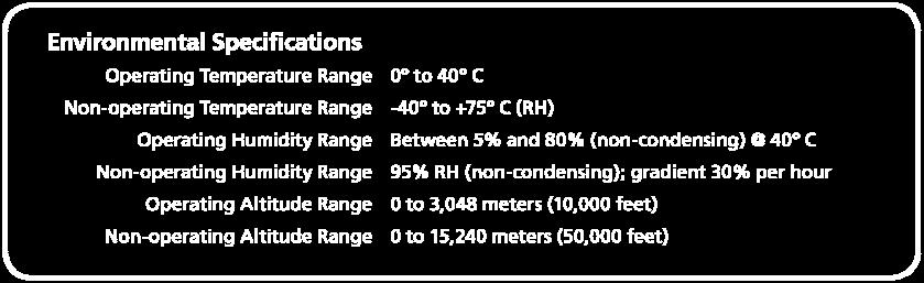
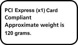
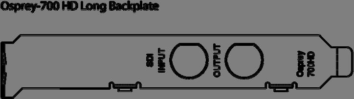
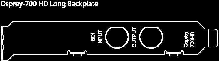
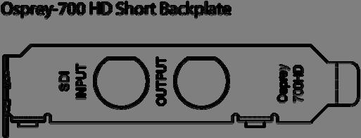
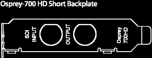
48 OSPREY HARDWARE SPECIFICATIONS
49 The Osprey-700e HD includes a second BNC connector (output) that is reserved for future applications. As shipped, the second connector can be used as an SDI Loop Out connection. The output of this port is a replica of the incoming SDI signal, valid for all SD and HD modes
Os prey. Analog PCIe Series User Guide For PCIe Video Capture Cards
 Os prey Analog PCIe Series User Guide For PCIe Video Capture Cards 2014 Osprey Video. All rights reserved. Osprey and SimulStream are registered trademarks of Osprey Video Microsoft, Windows, Windows
Osprey PCI User Guide
 2014 Osprey Video. All rights reserved. Osprey and SimulStream are registered trademarks of Osprey Video. Microsoft, Windows XP, Windows Server 2003, AVStream, DirectShow, Intel CoreDuo, and Windows Media
AVerMedia DarkCrystal HD Capture SDK II C729. English. Quick Guide
 AVerMedia DarkCrystal HD Capture SDK II C729 English Quick Guide FCC NOTICE (Class B) This device complies with Part 15 of the FCC Rules. Operation is subject to the following two conditions: (1) this
Cat s Eye edta-164 HDTV Tuner Card
 Cat s Eye edta-164 HDTV Tuner Card Installation Guide Version 1.0 VBox Communications Ltd. www.vboxcomm.com Copyright 2006, VBox Communications Ltd. All rights reserved. No part of this publication may
Hardware User s Manual
 Hardware User s Manual Megapixel Day & Night Economy Bullet Network Camera English 1 Table of Contents Before You Use This Product... 2 Regulatory Information... 3 Chapter 1 - Package Contents... 4 Chapter
Instruction Guide. USB External PC TV Tuner with Remote Control USBTVTUNER. The Professionals Source For Hard-to-Find Computer Parts
 TV TUNER USB External PC TV Tuner with Remote Control USBTVTUNER Instruction Guide * Actual product may vary from photo Revised: July 27, 2004 (Rev. C) The Professionals Source For Hard-to-Find Computer
USER MANUAL. 27 Full HD Widescreen LED Monitor L27ADS
 USER MANUAL 27 Full HD Widescreen LED Monitor L27ADS TABLE OF CONTENTS 1 Getting Started 2 Control Panel/ Back Panel 3 On Screen Display 4 Technical Specs 5 Care & Maintenance 6 Troubleshooting 7 Safety
SmartBox. User Manual. Turn your TV into a SmartTV! Plug n play. Wireless Dual Band
 SmartBox User Manual Turn your TV into a SmartTV! Wireless Dual Band Plug n play TV Remote Guide 5 4 1. ON / Stand by 2. Select package 1 6 2 3 7 3. 4. Favourite channels Electronic Program Guide (EPG
UFG-10 Family USER MANUAL. Frame Grabbers. Windows 8 Windows 7 Windows XP
 UFG-10 Family Frame Grabbers USER MANUAL Windows 8 Windows 7 Windows XP About this Manual Copyright This manual, Copyright 2014 Unigraf Oy. All rights reserved Reproduction of this manual in whole or in
Manual Version Ver 1.0
 The BG-3 & The BG-7 Multiple Test Pattern Generator with Field Programmable ID Option Manual Version Ver 1.0 BURST ELECTRONICS INC CORRALES, NM 87048 USA (505) 898-1455 VOICE (505) 890-8926 Tech Support
USER MANUAL. 27" 2K QHD LED Monitor L27HAS2K
 USER MANUAL 27" 2K QHD LED Monitor L27HAS2K TABLE OF CONTENTS 1 Getting Started 2 Control Panel/ Back Panel 3 On Screen Display 4 Technical Specs 5 Troubleshooting 6 Safety Info & FCC warning 1 GETTING
Instruction Guide. The TV Jockey Computer Monitor TV Tuner with Remote COMP2VGATVGB. The Professionals Source For Hard-to-Find Computer Parts
 VIDEO ADAPTER The TV Jockey Computer Monitor TV Tuner with Remote COMP2VGATVGB Instruction Guide * Actual product may vary from photo The Professionals Source For Hard-to-Find Computer Parts FCC COMPLIANCE
User s Guide W-E
 Presto! PVR ISDB User s Guide 518100-02-01-W-E-112307-02 Copyright 2007, NewSoft Technology Corp. All Rights Reserved. No portion of this document may be copied or reproduced in any manner without prior
USER MANUAL. 22" Class Slim HD Widescreen Monitor L215DS
 USER MANUAL 22" Class Slim HD Widescreen Monitor L215DS TABLE OF CONTENTS 1 Getting Started Package Includes Installation 2 Control Panel / Back Panel Control Panel Back Panel 3 On Screen Display 4 Technical
USER MANUAL Full HD Widescreen LED Monitor L215ADS
 USER MANUAL 21.5 Full HD Widescreen LED Monitor L215ADS TABLE OF CONTENTS 1 Getting Started 2 Control Panel/ Back Panel 3 On Screen Display 4 Technical Specs 5 Care & Maintenance 6 Troubleshooting 7 Safety
USER MANUAL Full HD Widescreen LED Monitor L215IPS
 USER MANUAL 21.5 Full HD Widescreen LED Monitor L215IPS TABLE OF CONTENTS 1 Getting Started 2 Control Panel/ Back Panel 3 On Screen Display 4 Technical Specs 5 Care & Maintenance 6 Troubleshooting 7 Safety
SportReplay Multichannel Video Recording and Instant Replay system
 SportReplay Multichannel Video Recording and Instant Replay system User s guide Revision from November 28, 2006 ReplayMachineSoftware 4.0.0 SoftLab-NSK, Ltd. Notice The information in this document is
USER MANUAL. 27 Full HD Widescreen LED Monitor L270E
 USER MANUAL 27 Full HD Widescreen LED Monitor L270E TABLE OF CONTENTS 1 Getting Started 2 Control Panel/ Back Panel 3 On Screen Display 4 Technical Specs 5 Care & Maintenance 6 Troubleshooting 7 Safety
2-/4-Channel Cam Viewer E-series for Automatic License Plate Recognition CV7-LP
 2-/4-Channel Cam Viewer E-series for Automatic License Plate Recognition Copyright Copyright 2015 by PLANET Technology Corp. All rights reserved. No part of this publication may be reproduced, transmitted,
User s Manual PV-NT1004+ For DOC NO: /06/28
 User s Manual For PV-NT1004+ DOC NO: 54-1004+-01 Rev.A 00/06/28 FCC Requirement This device has been certified to comply with the limits for a Class B computing device pursuant to Subpart J of Part 15
DVR-431 USB Wireless Receiver User Manual
 DVR-431 USB Wireless Receiver User Manual Thank you for using our wireless USB receiver, please read the following content carefully before using, it will help you make better use of this product. Introduction
VideoMate U3 Digital Terrestrial USB 2.0 TV Box Start Up Guide
 VideoMate U3 Digital Terrestrial USB 2.0 TV Box Start Up Guide Compro Technology, Inc. www.comprousa.com Copyright 2001-2005. Compro Technology, Inc. No part of this document may be copied or reproduced
Forward Т Software. SDI option. Revision as of December 19, Installation and Setup Guide. SoftLab-NSK Ltd.
 Forward Т Software SDI option Revision as of December 19, 2008. Installation and Setup Guide SoftLab-NSK Ltd. Notice The information in this document is subject to change without prior notice in order
MONOPRICE. 27" UHD IPS 4K Ultra Slim Aluminum Monitor. Quick User's Guide P/N 24658
 MONOPRICE 27" UHD IPS 4K Ultra Slim Aluminum Monitor P/N 24658 Quick User's Guide SAFETY WARNINGS AND GUIDELINES Please read this entire manual before using this device, paying extra attention to these
DVB-T USB SET-TOP BOX
 DVB-T USB SET-TOP BOX User Manual Version: 1.0 (February 2005) TRANSYSTEM INC. No.1-2 Li-Hsin Rd.I Science-Based Industrial Park, Hsinchu, Taiwan Tel:+886-3-5780393 Fax:+886-3-5784111 e-mail: sales@transystem.com.tw
Golf ball tracker. Instruction manual
 Golf ball tracker Instruction manual General Intended use The Prazza golf ball finder is intended for use on the golf course only and should never be used inside the home or any other enclosed environment.the
User Manual MODEL: KKF1500-PCAP. True FLAT P-CAP LCD Monitor. Installation Guide. 15 True FLAT P-CAP Touch LCD Monitor
 True FLAT P-CAP LCD Monitor User Manual Installation Guide 15 True FLAT P-CAP Touch LCD Monitor MODEL: KKF1500-PCAP i-tech Company LLC TOLL FREE: (888) 483-2418 EMAIL: info@itechlcd.com WEB: www.itechlcd.com
PL2410W LCD Monitor USER'S GUIDE.
 PL2410W LCD Monitor USER'S GUIDE www.planar.com Content Operation Instructions...1 Safety Precautions...2 First Setup...3 Front View of the Product...4 Rear View of the Product...5 Quick Installation...6
User s Manual. Welcome. About the product. Safety Notice
 Welcome Thank you for purchasing this product. Please read this manual thoroughly before use and retain it for future reference. We are confident you will enjoy this product and its many functions. About
Pablo II. The Picasso IV video-encoder. Manual. 18 August Copyright c 1997 Village Tronic Marketing GmbH Mühlenstraße Sarstedt Germany
 Pablo II The Picasso IV video-encoder Manual 18 August 1997 Copyright c 1997 Village Tronic Marketing GmbH Mühlenstraße 2 31157 Sarstedt Germany Technical Hotline: Tel. +49 (0)5066 / 7013-10 FAX: Tel.
17 19 PROFESSIONAL LCD COLOUR MONITOR ART
 17 19 PROFESSIONAL LCD COLOUR MONITOR ART. 41657-41659 Via Don Arrigoni, 5 24020 Rovetta S. Lorenzo (Bergamo) http://www.comelit.eu e-mail:export.department@comelit.it WARNING: TO REDUCE THE RISK OF FIRE
Table of Contents FCC COMPLIANCE STATEMENT... 4 WARNINGS AND PRECAUTIONS... 4 WARRANTY... 5 STANDARD WARRANTY... 5 TWO YEAR WARRANTY... 5 DISPOSAL...
 1 Table of Contents FCC COMPLIANCE STATEMENT... 4 WARNINGS AND PRECAUTIONS... 4 WARRANTY... 5 STANDARD WARRANTY... 5 TWO YEAR WARRANTY... 5 DISPOSAL... 6 1. INTRODUCTION... 7 FEATURES... 7 2. CONNECTIONS
Copyright. Notice. Edition. Company information. About this Manual
 UFG-05 Family Frame Grabbers USER MANUAL Windows 7 Windows XP Windows Vista About this Manual Copyright This manual, Copyright 2012 Unigraf Oy. All rights reserved Reproduction of this manual in whole
Wireless Studio. User s Guide Version 5.1x Before using this software, please read this manual thoroughly and retain it for future reference.
 4-743-161-12 (1) Wireless Studio User s Guide Version 5.1x Before using this software, please read this manual thoroughly and retain it for future reference. DWR-R01D/R02D/R02DN/R03D 2018 Sony Corporation
Reflecta Super 8 Scanner. User Manual
 Reflecta Super 8 Scanner User Manual 1 FEDERAL COMMUNICATIONS COMMISSION (FCC) STATEMENT This Equipment has been tested and found to comply with the limits for a class B digital device, pursuant to Part
User Manual MODEL: KK1500-TR. Touch Display LCD Monitor. Installation Guide. 15 Resistive Touch LCD Monitor
 Touch Display LCD Monitor User Manual Installation Guide 15 Resistive Touch LCD Monitor MODEL: KK1500-TR i-tech Company LLC TOLL FREE: (888) 483-2418 EMAIL: info@itechlcd.com WEB: www.itechlcd.com User
Cyan Sample. Forward T Software. Infotainment Channel Design Sample. Revision as of January 22, 2009 г. Instruction on Installation and Use
 Forward T Software Cyan Sample Infotainment Channel Design Sample Revision as of January 22, 2009 г. Instruction on Installation and Use SoftLab-NSK Notice The information in this document is subject to
USER MANUAL Full HD Widescreen LED Monitor L236VA
 USER MANUAL 23.6 Full HD Widescreen LED Monitor L236VA TABLE OF CONTENTS 1 Getting Started 2 Control Panel/ Back Panel 3 On Screen Display 4 Technical Specs 5 Care & Maintenance 6 Troubleshooting 7 Safety
Evolution Digital HD Set-Top Box Important Safety Instructions
 Evolution Digital HD Set-Top Box Important Safety Instructions 1. Read these instructions. 2. Keep these instructions. 3. Heed all warnings. 4. Follow all instructions. 5. Do not use this apparatus near
ELSA WINNER Series M a n u a l
 Manual Series 2002 Neue ELSA GmbH, Aachen (Germany) While the information in this manual has been compiled with great care, it may not be deemed an assurance of product characteristics. Neue ELSA GmbH
OPERATING MANUAL. DMX Demultiplexer 3012B Mk2
 last updated: 2007-03-08 OPERATING MANUAL DMX Demultiplexer 3012B Mk2 (C) SOUNDLIGHT 1995-2007 * ALL RIGHTS RESERVED * NO PART OF THIS MANUAL MAY BE REPRODUCED, DUPLICATED OR USED COMMERCIALLY WITHOUT
OPERATING MANUAL. DMX512 to DALI Dekoder 7044A-H Mk4
 last edited: 2014-08-12 OPERATING MANUAL DMX512 to DALI Dekoder 7044A-H Mk4 (C) SOUNDLIGHT 1996-2015 * ALL RIGHTS RESERVED * NO PART OF THIS MANUAL MAY BE REPRODUCED, DUPLICATED OR USED COMMERCIALLY WITHOUT
Hi-Vision TV Box. High Resolution TV BOX with PIP feature Model:174190
 Operational Manual Hi-Vision TV Box High Resolution TV BOX with PIP feature Model:174190 Thanks for your purchasing this product. Please read the Manual carefully before using it, and keep this manual
OPERATING GUIDE. HIGHlite 660 series. High Brightness Digital Video Projector 16:9 widescreen display. Rev A June A
 OPERATING GUIDE HIGHlite 660 series High Brightness Digital Video Projector 16:9 widescreen display 111-9714A Digital Projection HIGHlite 660 series CONTENTS Operating Guide CONTENTS About this Guide...
ForwardT Plugins. AutoDetect (SCTE-35) Automatic Ad insertion using SCTE-35 cue messages. Revision as of. October 28, User s Guide.
 Automatic Ad insertion using SCTE-35 cue messages. Revision as of. October 28, User s Guide.") ForwardT Plugins AutoDetect (SCTE-35) Automatic Ad insertion using SCTE-35 cue messages Revision as of. October 28, 205. User s Guide SoftLab-NSK Notice The information in this document is subject to change
ForwardT Plugins AutoDetect (SCTE-35) Automatic Ad insertion using SCTE-35 cue messages Revision as of. October 28, 205. User s Guide SoftLab-NSK Notice The information in this document is subject to change
It will cause malfunction if the monitor is operating with unspecified power supply
 User Manual / Installation Guide Model No. PTM-1525R/RT Warning! It will cause malfunction if the monitor is operating with unspecified power supply unit or incorrect power voltage. Do not exposure this
OPERATING INSTRUCTIONS TOM-0431IP
 OPERATING INSTRUCTIONS TOM-0431IP Table of Contents FCC Information -------------------------------------------------------------------- 2 Safety and Environmental Precautions ------------------------------------------------
Table of content. Table of content Introduction Concepts Hardware setup...4
 Table of content Table of content... 1 Introduction... 2 1. Concepts...3 2. Hardware setup...4 2.1. ArtNet, Nodes and Switches...4 2.2. e:cue butlers...5 2.3. Computer...5 3. Installation...6 4. LED Mapper
Stream Labs, JSC. Stream Logo SDI 2.0. User Manual
 Stream Labs, JSC. Stream Logo SDI 2.0 User Manual Nov. 2004 LOGO GENERATOR Stream Logo SDI v2.0 Stream Logo SDI v2.0 is designed to work with 8 and 10 bit serial component SDI input signal and 10-bit output
7. Image transmission functions
 This unit comes with a function for transmitting still images from the host computer to the unit via LAN and a function for importing still images from the unit into the host computer. The image transmission
HD Digital Set-Top Box Quick Start Guide
 HD Digital Set-Top Box Quick Start Guide Eagle Communications HD Digital Set-Top Box Important Safety Instructions WARNING TO REDUCE THE RISK OF FIRE OR ELECTRIC SHOCK, DO NOT EXPOSE THIS PRODUCT TO RAIN
User Manual. PC / HD Scaler. with advanced video processing. VGA to Component Video Component Video to VGA VGA to VGA Component to Component
 User Manual PC / HD Scaler with advanced video processing VGA to Component Video Component Video to VGA VGA to VGA Component to Component Model 1366 WARNINGS Read these instructions before installing or
RHP-IS DESKTOP IMAGE STABILIZER
 RHP-IS DESKTOP IMAGE STABILIZER Instruction Manual Firmware release 2.1 and above 2005-06-22 Rock2000.com P.O. BOX 4242, Middletown, New York, 10941, USA www.rock2000.com support@rock2000.com 2 Contents
Display-Shoot M642HD Plasma 42HD. Re:source. DVS-5 Module. Dominating Entertainment. Revox of Switzerland. E 2.00
 of Display-Shoot M642HD Plasma 42HD DVS-5 Module Dominating Entertainment. Revox of Switzerland. E 2.00 Contents DVS Module Installation DSV Connection Panel HDMI output YCrCb analogue output DSV General
USER MANUAL. 28" 4K Ultra HD Monitor L28TN4K
 USER MANUAL 28" 4K Ultra HD Monitor L28TN4K TABLE OF CONTENTS 1 Getting Started 2 Control Panel/ Back Panel 3 On Screen Display 4 Technical Specs 5 Care & Maintenance 6 Troubleshooting 7 Safety Info &
VNS2200 Amplifier & Controller Installation Guide
 VNS2200 Amplifier & Controller Installation Guide VNS2200 Amplifier & Controller Installation 1. Determine the installation location for the VNS2200 device. Consider the following when determining the
Disclaimer of Product & Services The information offered in this instruction manual is intended as a guide only. At all times, Datavideo Technologies
 TC-100 Table of Contents FCC COMPLIANCE STATEMENT... III WARNINGS AND PRECAUTIONS... III WARRANTY... V STANDARD WARRANTY... V THREE YEAR WARRANTY... V DISPOSAL... VI INTRODUCTION... 1 FEATURES... 1 HOW
DDW36C Advanced Wireless Gateway - Safety and Installation Product Insert. Federal Communications Commission (FCC) Interference Statement
 Interference Statement") DDW36C Advanced Wireless Gateway - Safety and Installation Product Insert Federal Communications Commission (FCC) Interference Statement This equipment has been tested and found to comply with the limits
DDW36C Advanced Wireless Gateway - Safety and Installation Product Insert Federal Communications Commission (FCC) Interference Statement This equipment has been tested and found to comply with the limits
22" Touchscreen LED Monitor USER'S GUIDE
 22" Touchscreen LED Monitor USER'S GUIDE Content Operation Instructions...1 Unpacking Instructions...2 Safety Precautions...2 Front View of the Product...3 Rear View of the Product...4 Quick Installation...5
1-In / 2-Out. HDMI Splitter User s Guide
 1-In / 2-Out HDMI Splitter 1500659 User s Guide We hope you enjoy your 1-In / 2-Out HDMI Splitter from RadioShack. This HDMI splitter allows the 4K2K digital signal from a HDMI device to be displayed on
CAUTION RISK OF ELECTRIC SHOCK NO NOT OPEN
 Evolution Digital HD Set-Top Box Important Safety Instructions 1. Read these instructions. 2. Keep these instructions. 3. Heed all warnings. 4. Follow all instructions. 5. Do not use this apparatus near
TECHNICAL MANUAL. Cheetah VIDEO MATRIX ROUTERS 3G VIDEO INPUT CARD WITH AUDIO DE-EMBEDDING AND 3G VIDEO OUTPUT CARD WITH AUDIO EMBEDDING
 TECHNICAL MANUAL Cheetah VIDEO MATRIX ROUTERS 3G VIDEO INPUT CARD WITH AUDIO DE-EMBEDDING AND 3G VIDEO OUTPUT CARD WITH AUDIO EMBEDDING Publication: 81-9059-0658-0, Rev. A August, 2009 Thank You!! for
Operating Instructions
 Marshall Electronics Broadcast A/V Division Model No. VSW-2200 4-Input Seamless SDI A/V Switcher Operating Instructions Table of Contents 1. Overview... 2. Features.... Package Contents... 4. Specifications...
PLL2210MW LED Monitor
 PLL2210MW LED Monitor USER'S GUIDE www.planar.com Content Operation Instructions...1 Safety Precautions...2 First Setup...3 Front View of the Product...4 Rear View of the Product...5 Quick Installation...6
THD601DC Set-top box
 THD601DC Set-top box Contents 1. Safety... 1 2. Appearance... 2 3. Rear Panel Connection... 3 4. Remote... 4 5 First Time Set-Up... 7 6. Network Settings... 8 6.1 Available Networks and Checking Current
Model#: IN-DI2MIRF 2MP Indoor Dome with True Day/Night, IR, Basic WDR, Fixed lens
 Model#: IN-DI2MIRF 2MP Indoor Dome with True Day/Night, IR, Basic WDR, Fixed lens Hardware User Manual (PoE) Ver.2013/01/17 Table of Contents 0. Precautions 3 1. Introduction 4 Package Contents...4 Features
HD Digital MPEG2 Encoder / QAM Modulator
 HD Digital MPEG2 Encoder / QAM Modulator HDMI In QAM Out series Get Going Guide ZvPro 800 Series is a one or two-channel unencrypted HDMI-to-QAM MPEG 2 Encoder / QAM Modulator, all in a compact package
Pilot. Quick Start Guide
 Pilot Quick Start Guide For further assistance, please visit www.thehovercam.com/support to download the manual or email us at support@thehovercam.com. 1-------------HDMI 7-----------Lightning slot 2-------------21.5"
Model#: IN-MDRI3MF. Hardware User Manual. 3MP Indoor Mini Dome with Basic WDR, Fixed lens. (PoE) Ver. 2013/02/04
 Ver. 2013/02/04") Model#: IN-MDRI3MF 3MP Indoor Mini Dome with Basic WDR, Fixed lens Hardware User Manual (PoE) Ver. 2013/02/04 Table of Contents 0. Precautions 3 1. Introduction 4 Package Contents... 4 Features and Benefits...
Model#: IN-MDRI3MF 3MP Indoor Mini Dome with Basic WDR, Fixed lens Hardware User Manual (PoE) Ver. 2013/02/04 Table of Contents 0. Precautions 3 1. Introduction 4 Package Contents... 4 Features and Benefits...
Scan Converter Installation Guide
 Scan Converter Installation Guide Software on supplied disks Please note: The software included with your scan converter is OPTIONAL. It is not needed to make the scan converter work properly. This software
2-/4-Channel Cam Viewer E- series for Automatic License Plate Recognition CV7-LP
 2-/4-Channel Cam Viewer E- series for Automatic License Plate Recognition Copyright 2-/4-Channel Cam Viewer E-series for Automatic License Plate Recognition Copyright 2018 by PLANET Technology Corp. All
DCL9AW. User Manual. English
 DCL9AW User Manual English PRECAUTIONS Information for users applicable in European Union countries 1 Information for users applicable in United States of America 1 Installation 1 Power connection 1 Maintenance
RADEON 7200 RADEON 7000
 RADEON 7200 RADEON 7000 User s Guide Version 3.0 P/N 137-40299-30 Rev. B Copyright 2002, ATI Technologies Inc. All rights reserved. ATI and all ATI product and product feature names are trademarks and/or
RADEON User s Guide P/N
 RADEON 9000 User s Guide P/N 137-40442-10 Copyright 2002, ATI Technologies Inc. All rights reserved. ATI and all ATI product and product feature names are trademarks and/or registered trademarks of ATI
TV Tuner Card User Manual
 TV Tuner Card User Manual P/N: 400108013805 Ver: 3.00.000.0 Date: 2003-11-15 Copyright and Trademark Notice All rights reserved. Information in this document is subject to change without notice. No part
HiPix DTV-200 HDTV MultiMedia Control Card for your PC. Users Manual
 HiPix DTV-200 HDTV MultiMedia Control Card for your PC Users Manual Version 1.2 June, 2001 TELEMANN HIPIX DTV-200 SOFTWARE END-USER LICENSE This is a legally relevant License (the "License") between Global
PCI Express JPEG Frame Grabber Hardware Manual Model 817 Rev.E April 09
 PCI Express JPEG Frame Grabber Hardware Manual Model 817 Rev.E April 09 Table of Contents TABLE OF CONTENTS...2 LIMITED WARRANTY...3 SPECIAL HANDLING INSTRUCTIONS...4 INTRODUCTION...5 OPERATION...6 Video
HD Digital MPEG2 Encoder / QAM Modulator
 HD Digital MPEG2 Encoder / QAM Modulator YPrPb VGA In QAM Out series Get Going Guide ZvPro 600 Series is a one or two-channel Component or VGA-to-QAM MPEG 2 Encoder/ Modulator, all in a compact package
VIDEO GRABBER. DisplayPort. User Manual
 VIDEO GRABBER DisplayPort User Manual Version Date Description Author 1.0 2016.03.02 New document MM 1.1 2016.11.02 Revised to match 1.5 device firmware version MM 1.2 2019.11.28 Drawings changes MM 2
AVTuner PVR Quick Installation Guide
 AVTuner PVR Quick Installation Guide Introducing the AVTuner PVR The AVTuner PVR allows you to watch, record, pause live TV and capture high resolution video on your computer. Features and Benefits Up
USER MANUAL. KW-11T Wireless High Definition Transmitter. KW-11R Wireless High Definition Receiver MODELS: P/N: Rev 9
 KRAMER ELECTRONICS LTD. USER MANUAL MODELS: KW-11T Wireless High Definition Transmitter KW-11R Wireless High Definition Receiver P/N: 2900-300194 Rev 9 Contents 1 Introduction 1 2 Getting Started 2 2.1
P-2 Installing the monitor (continued) Carry out as necessary
 Carry out as necessary") P-2 Installing the monitor (continued) Carry out as necessary Using the monitor without the bezel MDT552S satisfies the UL requirements as long as it is used with the bezel attached. When using the monitor
P-2 Installing the monitor (continued) Carry out as necessary Using the monitor without the bezel MDT552S satisfies the UL requirements as long as it is used with the bezel attached. When using the monitor
CDV07. Analog video distribution amplifier(s)
") CDV07 Analog video distribution amplifier(s) TECHNICAL MANUAL CDV07 Analog video distribution amplifier Lange Wagenstraat 55 NL-5126 BB Gilze The Netherlands Phone: +31 161 850 450 Fax: +31 161 850 499
CDV07 Analog video distribution amplifier(s) TECHNICAL MANUAL CDV07 Analog video distribution amplifier Lange Wagenstraat 55 NL-5126 BB Gilze The Netherlands Phone: +31 161 850 450 Fax: +31 161 850 499
FlyTV Express M5 MST-T 2 A 2
 FlyTV Express M5 MST-T 2 A 2 User Manual Animation Technologies Inc. www.lifeview.com Ver: 1.0 Copyright and Trademark Notice 2006 by Animation Technologies Inc. All rights reserved. Information in this
Instruction Guide. Component/Composite/S-Video to DVI-D/HDTV Scaler and Converter Component/Composite/S-Video to VGA/HDTV Scaler and Converter
 VIDEO SCALER Component/Composite/S-Video to DVI-D/HDTV Scaler and Converter Component/Composite/S-Video to VGA/HDTV Scaler and Converter VID2DVIDTV (DVI) VID2VGATV (VGA) Instruction Guide * Actual product
MaxView Cinema Kit Quick Install Guide
 SYSTEM SETUP The MaxView will work at any of the following display settings: INSTALLATION MaxView Cinema Kit Quick Install Guide Step 1 - Turn off your computer. Disconnect your monitor s VGA cable from
Neue ELSA GmbH Sonnenweg Aachen Germany
 2002 Neue ELSA GmbH, Aachen (Germany) While the information in this manual has been compiled with great care, it may not be deemed an assurance of product characteristics. Neue ELSA GmbH shall be liable
About Final Cut Pro Includes installation instructions and information on new features
 apple About Final Cut Pro 1.2.5 Includes installation instructions and information on new features This document includes installation instructions and describes features and enhancements of Final Cut
ATI TV Wonder 650 PCIe
 ATI TV Wonder 650 PCIe User Guide ii 2007 Advanced Micro Devices Inc. All rights reserved. The contents of this document are provided in connection with Advanced Micro Devices, Inc. ( AMD ) products. AMD
CGA0101 Wireless Cable Gateway Quick Installation Guide
 Package Contents CGA0101 cable modem * 1 Quick Installation Guide * 1 RJ-45 CAT 5e cable * 1 Rear Panel and Hardware Connection 12 V/1.5 A Power Adaptor * 1 Telephone cord * 1 This chapter describes the
DA IN 1-OUT LINE DRIVER WITH EQUALIZATION + AUDIO USER S GUIDE
 MANUAL PART NUMBER: 400-0430-001 1-IN 1-OUT LINE DRIVER WITH UALIZATION + AUDIO USER S GUIDE TABLE OF CONTENTS Page PRECAUTIONS / SAFETY WARNINGS... 2 GENERAL...2 GUIDELINES FOR RACK-MOUNTING...2 INSTALLATION...2
DVB-S 100 Installation Manual
 DVB-S 100 Installation Manual Contents V2.0 Chapter 1 : DVB-S 100 PCI Card Hardware Installation...2 1.1 Package Contents...2 1.2 System Requirements...2 1.3 Hardware Installation...2 Chapter 2 : DVB-S
Gazer VI700A-SYNC/IN and VI700W- SYNC/IN INSTALLATION MANUAL
 Gazer VI700A-SYNC/IN and VI700W- SYNC/IN INSTALLATION MANUAL Contents List of compatible cars... 3 Package contents... 4 Special information... 6 Car interior disassembly and connection guide for Ford
Getting Started After Effects Files More Information. Global Modifications. Network IDs. Strand Opens. Bumpers. Promo End Pages.
 TABLE of CONTENTS 1 Getting Started After Effects Files More Information Introduction 2 Global Modifications 9 Iconic Imagery 21 Requirements 3 Network IDs 10 Summary 22 Toolkit Specifications 4 Strand
PQ Labs Multi-Touch Screen G 2 Overlay
 PQ Labs Multi-Touch Screen G 2 Overlay User Manual 2.0 52 inch PQ Labs Multi-Touch Overlay For 52 inch LCD/Plasma display Copyright 2008 PQ Labs Inc. All Rights Reserved. Disclaimer The information in
CAPTURE CAPTURE. VERSiON 1.2. Specialists in Medical. Digital Imaging Solutions
 CAPTURE Add-on module for capturing images from analog video sources CAPTURE anything to DICOm VERSiON 1.2 Specialists in Medical Digital Imaging Solutions iq-capture Connect any medical device to your
ESI VLS-2000 Video Line Scaler
 ESI VLS-2000 Video Line Scaler Operating Manual Version 1.2 October 3, 2003 ESI VLS-2000 Video Line Scaler Operating Manual Page 1 TABLE OF CONTENTS 1. INTRODUCTION...4 2. INSTALLATION AND SETUP...5 2.1.Connections...5
AWT150C/AWT150CS/ AWT151C CCD Camera
 AWT150C/AWT150CS/ AWT151C CCD Camera ISSUED OCTOBER 2018 WARNING Failure to follow all instructions and safety precautions in this manual, in the vehicle and body manufacturers' manuals and on the safety
CINEGEARS MULTI AXIS FOLLOW FOCUS KIT V3 MANUAL BOOK Cine Gears INC. All Rights Reserved.
 CINEGEARS MULTI AXIS FOLLOW FOCUS KIT V3 MANUAL BOOK Statement of Conditions In the interest of improving internal design, operational function, and/or reliability, Cine Gears Inc. reserves the right to
MONOPRICE. SDI to Multiformat Video Converter with Scaler. User's Manual P/N 15776
 MONOPRICE SDI to Multiformat Video Converter with Scaler P/N 15776 User's Manual SAFETY WARNINGS AND GUIDELINES This device is intended for indoor use only. Do not expose this device to water or moisture