ARC21. Broadcast quality bi-directional aspect ratio converter with video delay
|
|
|
- Albert Norton
- 5 years ago
- Views:
Transcription
1 ARC21 Broadcast quality bi-directional aspect ratio converter with video delay
 Lange")

2 TECHNICAL MANUAL ARC21 Broadcast quality bi-directional aspect ratio converter with video delay (15 frames) Lange Wagenstraat 55 NL-5126 BB Gilze The Netherlands Phone: Fax: Web:
3 WARNING: TO REDUCE THE RISK OF FIRE OR ELECTRICAL SHOCK, DO NOT EXPOSE THIS APPLIANCE TO RAIN OR MOISTURE ALWAYS disconnect your entire system from the AC mains before cleaning any component. The product frame (SFR18 or SFR04) must be terminated with three-conductor AC mains power cord that includes an earth ground connection. To prevent shock hazard, all three connections must always be used. NEVER use flammable or combustible chemicals for cleaning components. NEVER operate this product if any cover is removed. NEVER wet the inside of this product with any liquid. NEVER pour or spill liquids directly onto this unit. NEVER block airflow through ventilation slots. NEVER bypass any fuse. NEVER replace any fuse with a value or type other than those specified. NEVER attempt to repair this product. If a problem occurs, contact your local Axon distributor. NEVER expose this product to extremely high or low temperatures. NEVER operate this product in an explosive atmosphere. Warranty: Axon warrants their products according to the warranty policy as described in the general terms. That means that Axon Digital Design BV can only warrant the products as long as the serial numbers are not removed. Copyright AXON Digital Design B.V. Date created: Date last revised: Axon, the Axon logo and Synapse are trademarks of Axon Digital Design B.V. This product complies with the requirements of the product family standards for audio, video, audio-visual entertainment lighting control apparatus for professional use as mentioned below. EN60950 EN : 1996 EN : 1996 Safety Emission Immunity Axon Digital Design ARC21 Tested To Comply With FCC Standards FOR HOME OR OFFICE USE This device complies with part 15 of the FCC Rules Operation is subject to the following two conditions: (1) This device may cause harmful interference, and (2) This device must accept any interference received, including interference that may cause undesired operation. 1
4 Table of Contents Chapter 1 Introduction to Synapse 3 An introduction to Synapse 3 Local Control Panel 3 Remote Control Capabilities 3 Chapter 2 Unpacking and Placement 4 Unpacking 4 Placing the card 4 Chapter 3 A Quick Start 5 When powering-up 5 Default settings 5 Changing parameters and settings 5 Front Panel Control 5 Example of changing parameter using 6 Front Panel control Synapse SetUp Software 7 Menu Structure Example 7 Chapter 4 The ARC21 card 8 Introduction 8 Video Index 8 Chapter 5 Settings Menu 10 Chapter 6 Status Menu 18 Chapter 7 Events Menu 19 Chapter 8 LED Indication 21 Chapter 9 Block Schematic 22 Chapter 10 Connector panel 23 Chapter 11 Specifications 25 Appendix One 26 2
5 1 Introduction to Synapse An Introduction to Synapse Synapse is a modular system designed for the broadcast industry. High density, intuitive operation and high quality processing are key features of this system. Synapse offers a full range of converters and processing modules. Please visit the AXON Digital Design Website at to obtain the latest information on our new products and updates. Local Control Panel The local control panel gives access to all adjustable parameters and provides status information for any of the cards in the Synapse frame, including the Synapse rack controller. The local control panel is also used to back-up and restore card settings. Please refer to the RRC18, RRC10 and RRC04 manuals for a detailed description of the local control panel, the way to set-up remote control over IP and for frame related settings and status information. Remote Control Capabilities The remote control options are explained in the rack controller (RRC18/RRC10/RRC04) manual. The method of connection to a computer using Ethernet is described in the RRC manual.! CHECK-OUT: SYNAPSE SET-UP SOFTWARE WILL INCREASE SYSTEM FLEXIBILITY OF ONE OR MORE SYNAPSE FRAMES Although not required to set up a Synapse frame, you are strongly advised to use a remote personal computer or laptop PC with the Synapse set up software as this increases the ease of use and understanding of the modules. 3
6 2 Unpacking and Placement Unpacking The Axon Synapse card must be unpacked in an anti-static environment. Care must be taken NOT to touch components on the card always handle the card carefully by the edges. The card must be stored and shipped in anti-static packaging. Ensuring that these precautions are followed will prevent premature failure from components mounted on the board. Placing the card The Synapse card can be placed vertically in an SFR18 frame or horizontally in an SFR04 frame. Locate the two guide slots to be used, slide in the mounted circuit board, and push it firmly to locate the connectors. Correct insertion of card is essential as a card that is not located properly may show valid indicators, but does not function correctly. REMARK: On power up all LEDs will light for a few seconds, this is the time it takes to initialise the card. 4
7 3 A Quick Start On Powering-up On powering up the Synapse frame, the card set will use basic data and default initialisation settings. All LEDs will light during this process. After initialisation, several LEDs will remain lit the exact number and configuration is dependant upon the number of inputs connected and the status of the inputs. Default settings In its default condition, the ARC21 will act as an aspect ratio converter set to pass through the input signal without a change in aspect ratio with a delay of 1 frame and 2 lines. Changing settings and parameters The front panel controls or the Synapse Set-Up Software can be used to change settings. An overview of the settings can be found in chapter 5, 6 and 7 of this manual. Front Panel Control Front Panel Display and Cursor [No Alarms] Settings are displayed and changed as follows; Use the cursor arrows on the front panel to select the menu and parameter to be displayed and/or changed. Press Press Press Press To go forward through the menu structure. To go back through the menu structure. To move up within a menu or increase the value of a parameter. To move down through a menu or decrease the value of a parameter. REMARK: Whilst editing a setting, pressing twice will reset the value to its default. 5
8 Example of changing parameters using front panel control With the display as shown below RRC18 [Select Card] >S01=ARC21 Pressing the selects the ARC21 in frame slot 01. The display changes to indicate that the ARC21 has been selected. In this example the Settings menu item is indicated. AEC21 [Select Menu] >Settings Pressing the selects the menu item shown, in this example Settings. (Pressing or will change to a different menu eg Status, Events). The display changes to indicate that the ARC21 Settings menu item SDI-Format has been selected and shows that it current setting is Auto. ARC21 [Settings] >SDI-Format=Auto Pressing the selects the settings item shown, in this example SDI-Format. (Pressing or will change to a different setting, eg Mode, H-Delay). The display changes to indicate that the ARC21 Edit Setting menu item SDI-Format has been selected. ARC21 [Edit etting] SDI-Format>Auto To edit the setting of the menu item press or. All menu items can be monitored and/or changed in this way. Changing a setting has an immediate effect. 6
9 Synapse SetUp Software Synapse SetUp Software can be used to change the settings of Synapse modules from a PC, either locally or remotely. The software enables communication based on TCP/IP between the setup PC and Synapse frames/modules. Each Synapse frame is addressed through its rack controller s unique IP address, giving access to each module, its menus and adjustment items. The Synapse SetUp software has access to data contained within the Synapse module and displays it on a GUI. The software has an intuitive structure following that of the module that it is controlling. Having selected the desired Frame and Module from the GUI Synapse Network View, select the menu item that you wish to open. Opening the menu item gives a complete list of available properties with their associated Value. For example to change a setting e.g. SDI-Format, select SDI- Format form the list of settings by double clicking to open a dialogue box. The dialogue box allows parameters to be changed or set to default value. On completion close the dialogue box. Menu Structure Example Slot Module Item Parameter Setting S02 Identity S0 ARC21 Setting SDI- Auto 1 s Format S00 RRC18 Status Mode 625 Events Ref-Input 525 H-Delay REMARK: Further information about Front Panel Control and Synapse Set Up Software can be obtained from the RRC18 and RRC04 operational manuals. 7
10 4 The ARC21 Card Introduction The ARC21 features high quality and optimized conversion between different aspect ratios like 4:3, 14:9 and 16:9 with full 10- bit resolution (the internal processing however is more precise). High quality vertical filtering is reached by using a temporal (3 fields), 12 lines FIR filter. Aspect Ratio handling The ARC21 can convert between a wide range of aspect ratios, form 4:3 to 21:9. The aspect ratios can be switched using WSS, VI, GPI or manual control. SDI interfaces Input and outputs are SDI, 10-bit serial digital video (270 Mb). No genlock reference is needed because the total delay of the ARC21 is fixed. Analog Monitoring An analog preview monitoring output is provided with several comprehensive functions. Transparent ANC handling Any data (like embedded audio) in the horizontal and vertical blanking periods is reinserted on the output with the correct delay. Also included is full EDH processing. 16 presets Sixteen presets, which contain the variables for different conversion modes, can be stored in non-volatile memory. The presets can be selected manually, by GPI contacts or automatically, based on Video Index information or Wide Screen Signaling information. Variable Video Delay The minimum delay is 1 frame and 2 lines and the maximum is 15 frames and 624 lines. 8
11 Video Index The Video Index data is in accordance with the SMPTE Recommended Practice RP186. The ARC21 supports Class 1.1 only. Class 1.1 is mandatory and holds information required to display the signal. 12 octets 12 octets 24 octets SAV Class 1 Class 2 Class 3 Unused EAV Class 1.1 CRCC Class 1.2 CRCC Class 1.3 CRCC Class 2.1 CRCC Class 2.2 CRCC Class 2.3 CRCC 3 octets 1 3 octets 1 3 octets 1 3 octets 1 3 octets 1 3 octets 1 9
12 Aspect ratio standards Widescreen Signalling (WSS) and Video Index (VI) are used to transport aspect ratio information in the video signal. VI is only used by other broadcasting equipment which all act differently. WSS data is used by Modern 16:9 consumer televisions to switch to different types of aspect ratio displays. The following table shows example screens of how different WSS signals are displayed on a modern Pioneer TV. Keep in mind that various consumer TVs act differently to the WSS data as shown here. WSS setting Aspect ratio Picture placement Most used settings are marked green. With most TVs the display type for 1_vid is user defined. Active lines Result on 16:9 screens with full 4:3 source Result on 16:9 screens with full 16:9 source Result on 16:9 screen with letterboxed 16:9 source 1_vid 4:3 Full 576 2_vid 14:9 Letterbox Centre 504 3_vid 14:9 Letterbox Top 504 4_vid 16:9 Letterbox Centre 430 5_vid 16:9 Letterbox Top 430 6_vid >16:9 Letterbox deeper than 16:9 7_vid 14:9 Full 4:3, framed to be "14:9-safe" 576 8_vid 16:9 Full-height 16:9 (anamorphic)
13 5 Settings Menu Introduction The settings menu displays the current state of each setting within the ARC21 and enables the item to be changed or adjusted. Settings can be changed using the front panel of the Synapse frame (SFR18 or SFR04) or Synapse SetUp software. Please refer to chapter 3 for information on the Synapse front panel control and Synapse SetUp software. SDI-Format The SDI-format menu item selects the input video standard, 525, 625 and Auto can be selected. The default setting is Auto. Control The Control menu item determines how the ARC20 is controlled. The settings of Control are, Manual, Video Index, VI_manual, WSS-std, WSS-std_man, WSS-ext, WWS-ext_man, GPI-priori, GPI-binary and GPI- Slave (if used in combination with Axon GPI16 card). GPI-priori: when the local GPI input is used, the GPI contact_1 is routed to Preset_1 (up to GPI contact_8 to Preset_8 - See GPI-priori table) GPI-binary sets the presets by using the local GPI-contacts in a binary way (See table below). When set to VI_manual, WSS_ext_man or WSS_std_man, the ARC follows the control information (ie VI, WSS) of the input signal. When no control information is present, the preset set in "No-Control" will be loaded. Status item "Actual_Ctrl" shows the actual control mode, and will show "no control" when control information is absent. When set to hold, the card holds its current preset. However, when No-control is set to any preset but hold, the preset which is loaded upon the absence of control information, may be overridden. This is done by manually selecting a "Preset". It is also possible to manually override the preset when wrong control information (i.e. a false AFD) is fed to the card. Status item "Actual_Ctrl" will show "override" when manually overridden. When control information changes when manually overridden, i.e. WSS changes AFD, or VI becomes available after it has been lost, then the ARC will follow the control again. Please note that when manually overriding the preset, the "no_control" setting will follow, unless it is set to hold. 11
14 The default setting is Manual. The following table gives the preset selection when Control is set to Video Index or WSS-ext. Incoming Format ADF-only Menu Setting Preset Selection 4:3_0 On/Off 1 4:3_1 On/Off 2 4:3_2 On/Off 3 4:3_3 On/Off 4 4:3_4 On/Off 5 4:3_5 On/Off 6 4:3_6 On/Off 7 4:3_7 On/Off 8 16:9_0 Off 9 16:9_0 On 1 16:9_1 Off 10 16:9_1 On 2 16:9_2 Off 11 16:9_2 On 3 16:9_3 Off 12 16:9_3 On 4 16:9_4 Off 13 16:9_4 On 5 16:9_5 Off 14 16:9_5 On 6 16:9_6 Off 15 16:9_6 On 7 16:9_7 Off 16 16:9_7 On 8 The following table gives the preset selection when Control is set to WSS-std. Incoming Standard Preset Selection Standard 1 1 Standard 2 2 Standard 3 3 Standard 4 4 Standard 5 5 Standard 6 6 Standard 7 7 Standard
15 GPI_BINARY table Select Preset Gpi_1 contact Gpi_2 contact Gpi_3 contact Gpi_4 contact Preset_1 open open open open Preset_2 closed open open open Preset_3 open closed open open Preset_4 closed closed open open Preset_5 open open closed open Preset_6 closed open closed open Preset_7 open closed closed open Preset_8 closed closed closed open Preset_9 open open open closed Preset_10 closed open open closed Preset_11 open closed open closed Preset_12 closed closed open closed Preset_13 open open closed closed Preset_14 closed open closed closed Preset_15 open closed closed closed Preset_16 closed closed closed closed GPI_PRIORI TABLE O = OPEN 1 = CLOSED X = DON T CARE CONTACT NUMBER / GPI# Hold previous Preset X Preset X X Preset X X X Preset X X X X Preset X X X X X Preset X X X X X X Preset 7 1 X X X X X X X Preset 8 13
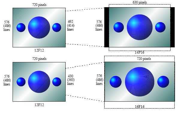
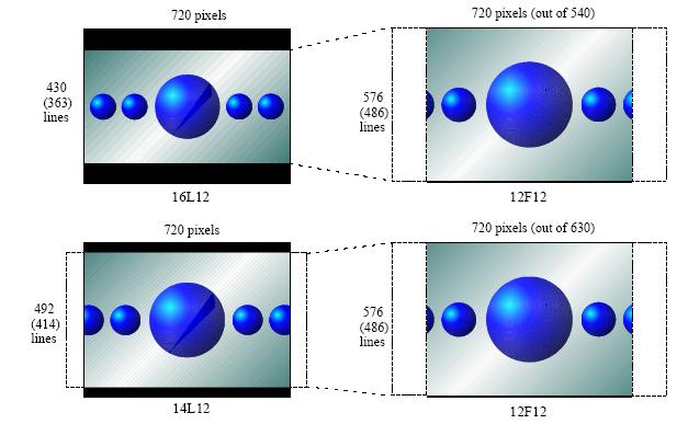
16 Preset The ARC21 has 16 factory preset aspect ratio conversion modes they are as follows; Preset No. Menu Function Conversion Mode 1 #1 Pass through 12F12 12F12 2 #2 4:3 to 16:9 as 4:3 pillarbox 12F12 12P16 3 #3 4:3 to 16:9 as 14:9 pillarbox 12F12 14P16 4 #4 4:3 to 16:9 as 16:9 full field 12F12 16F16 5 #5 16:9 to 4:3 as 16:9 letterbox 16F16 16L12 6 #6 16:9 to 4:3 as 14:9 letterbox 16F16 14L12 7 #7 16:9 to 4:3 as 4:3 full field 16F16 14F12 8 #8 Pass through 12F12 12F12 9 #9 Pass through 12F12 12F12 10 #10 Pass through 12F12 12F12 11 #11 Pass through 12F12 12F12 12 #12 Pass through 12F12 12F12 13 #13 Pass through 12F12 12F12 14 #14 Pass through 12F12 12F12 15 #15 Pass through 12F12 12F12 16 #16 Pass through 12F12 12F12 The default setting of Preset is #1. NOTE: If the menu item is preceded by a # sign, it is possible to add this setting to a preset. The presets are stored in memory. #Inp-Format The menu item #Inp-Format selects the aspect ratio of the input signal. The aspect ratio settings are as follows; Setting Aspect Ratio 12F12 4:3 Full 13L12 13:9 picture displayed Letterbox in 4:3 environment 14L12 14:9 picture displayed Letterbox in 4:3 environment 15L12 15:9 picture displayed Letterbox in 4:3 environment 16L12 16:9 picture displayed Letterbox in 4:3 environment 21L12 21:9 picture displayed Letterbox in 4:3 environment 12P16 4:3 picture displayed Pillarbox in a 16:9 environment 13P16 13:9 picture displayed Pillarbox in a 16:9 environment 14P16 14:9 picture displayed Pillarbox in a 16:9 environment 15P16 15:9 picture displayed Pillarbox in a 16:9 environment 16F16 16:9 Full 21L16 21:9 picture displayed Letterbox in 16:9 environment 21F21 21:9 Full The default setting of #Inp-Format is 12F12. 14
17 #Out-Format The menu item #Out-Format selects the aspect ratio of the output signal. The aspect ratio settings are as follows; Setting Aspect Ratio 12F12 4:3 Full 13L12 13:9 picture displayed Letterbox in 4:3 environment 14L12 14:9 picture displayed Letterbox in 4:3 environment 15L12 15:9 picture displayed Letterbox in 4:3 environment 16L12 16:9 picture displayed Letterbox in 4:3 environment 21L12 21:9 picture displayed Letterbox in 4:3 environment 12P16 4:3 picture displayed Pillarbox in a 16:9 environment 13P16 13:9 picture displayed Pillarbox in a 16:9 environment 14P16 14:9 picture displayed Pillarbox in a 16:9 environment 15P16 15:9 picture displayed Pillarbox in a 16:9 environment 16F16 16:9 Full 21L16 21:9 picture displayed Letterbox in 16:9 environment 21F21 21:9 Full The default setting of #Out-Format is 12F12. #Pan This item sets the horizontal position of the picture. The value range is from px to px (pixels).. The increment is 1 pixel steps. The default value (and middle) is 0.00 #Tilt This item sets the vertical position of the picture. The value range is from ln to ln (lines). The increment is 1ln. The default value (and middle) is 0.00 #H_blank The menu item #H_Blank set the amount by which the picture is blanked horizontally. #H_Blank has an adjustment range of 0 px (pixels) to 199 px. The default setting is 0 px (pixels). #V_blank The menu item #V_Blank set the amount by which the picture is blanked vertically. #V_Blank has an adjustment range of 0 ln (TV lines) to 130 ln. The default setting is 0 ln (TV lines) 15
18 #Filter This meu item selects the filter mode for Video, Film, Mixed and Film_Eff. Filter modes have an effect when the vertical filtering is active. Video mode is the default setting and is normally used. This filter mode processes video fields. In order to improve the vertical resolution of the video being processed, three video fields are used. Film mode is used for video material that has been scanned from a film source. The ARC takes advantage of the fact that there is no motion between fields. Two fields are interlaced in advance of the vertical filter to give a non interlaced frame, this improves vertical resolution. Mixed mode utilizes a combination of filter coefficients from Film mode and video mode to reduce ghosting artefacts that result from post production effects and aspect ratio changes. Film_Eff (Film Effect) mode used to give a film scanned look to video material. In this mode the vertical filter coefficients change with the same sequence as in film-mode. REMARK: For a complete description of the different filter modes please refer to Appendix One. #VI-Insert The Video Index insertion menu enables the generation of Video Index (VI) information. Video Index is used to trigger cascaded equipment that process wide screen manipulation, aspect ratio converters for example. #VI-Insert can be set to 4:3_0 to 4:3_7, 16:9_0 to 16:9_7 and Off. The default setting is 4:3_0. #WSS-Insert The WSS insertion menu selects the WSS mode. Off, Standard, Extended and Blank can be set. The WSS extended is a special mode that uses the physical structure of WSS but with a VI like data settings. The default setting is Off. #WSS-Std-Ins #WSS-Std-Ins is activated if Standard is selected in the setting menu item #WSS-Insert. The WSS standard has 16 settings 8 for video and 8 for film. Selection is made between 1_vid to 8_vid, or 1_flm to 8_flm and NA. The default setting is 1_vid. 16
19 #WSS-Ext-Ins #WSS-Ext-Ins is activated if Extended is selected in the setting menu item #WSS-Insert. WSS-Ext-Ins sets the WSS extended format. The setting can be within the range 4:3_0, 4:3_1, 4:3_2, etc., to 16:9_0, 16:9_1, 16:9_2 etc. and Off. The default setting is 4:3_0. #WSS-GPI-Ins #WSS-GPI-Ins is activated if Extended is selected in the setting menu item #WSS-Insert. The #WSS-GPI-Ins setting sets the programmable GPIs that are supported by WSS. selection of 4 GPI can be made:, 4, _4 etc to1234. The default setting is. #GPI-Out-Slv The menu item #GPI-Out-Slv selects which GPI outputs of the slave GPI16 card are used. The available GPI outputs can be set between #1 to #16. The default setting is #1. Prvw_Config Prvw_Config determines the configuration of the preview output connectors. Cv_Y_C: G_B_R: Y_Cb_Cr: Composite Video, and separate Y/C Component GBR Component YCbCr The default setting is Cv_Y_C. Prvw_Signal The settings menu item Prvw_Signal allows selection between the Input and the Processed signal fro the preview output. The default setting is Input. Prvw_Marker The settings menu item Prvw_Marker sets the condition of the preview marker. The setting of Prvw_Marker are On or Off and movement speeds S1 to S7. The default setting is On. EDH-Gen The EDH generator inserts EDH into the output signal. This setting allows the user to switch the built in EDH generator On or Off. The default setting is On. 17
20 EDH-Det This setting allows the user to choose between Active-Picture (Active-P) or Full- (Full-F) EDH detection. Can also be set to Off. The default setting is Full-F. CC_525 When used with 525 line signals, the setting menu item CC_525 enables the closed captioning lines L21 or L21+L22 and the corresponding lines in field two to pass transparently through the ARC21. These lines are not scaled or filtered. The default setting of CC_525 is Off. ADF-only ADF-only allows the ARC21 to react only to changes in the ADF (Active Format Descriptor) values in the Video Index or WSS-ext see above setting items. The settings of ADF-Only are On and Off. The default setting is Off. Frame-Delay The Frame-Delay setting allows adjustment of the delay of the output signal. The Frame-Delay setting gives a delay in the addition to the input. The adjustment range of the frame delay is 1 frame\15 frames Line-Delay The Line-Delay setting allows adjustment of the delay of the output signal. The Line-Delay setting gives a delay in the addition to the input. The adjustment range of the line delay is 2 lines till 624 lines. Sample-Delay The Sample-Delay setting allows adjustment of the delay of the output signal (pixels). The Sample-Delay setting gives a delay in the addition to the input. The adjustment of the line delay is 0 samples to 1727 samples. Blank-ANC The Blank-ANC setting determines the ancillary blanking mode. Off, H, V or H+V are the available settings. The Blank-ANC setting blanks the ancillary data in the horizontal and/or vertical blanking interval. The default setting is Off. Soften_edges When this setting is On, the left and right edges of the picture are smoothened in Pillarbox output formats or when blanking is enabled. Turned Off the edges remain unsmoothed. By default, this setting is set to On. 18
21 6 Status Menu Introduction The status menu indicates the current status of each item listed below. SDI-Input This status item indicates the presence of a valid Serial video signal at the SDI input. SDI-Input indicates if an input signal is NA (not available) or Present. Format-Det 625 Lines and 525 Lines standards can be detected as the valid input signal format, 625/50 and 525/60 are recognised as valid inputs. EDH-Stat EDH-Stat, indicates the status of the EDH within the incoming SDI signal. OK is indicated if the status of the detected EDH does not indicate errors. UES is shown if an EDH data block is not present. EDA is displayed if an EDH error has previously been detected by another card in the SDI chain. EDH is displayed if a previously undetected EDH error is detected by this device. GPI-in-local The status item GPI-in-Local indicates which of the eight local GPI inputs are activated. The status item displays #1..#8. GPI-in-slave The status item GPI-in-slave indicates which of the slave GPI inputs are activated (up to 16). The status item displays #1..#16. VI-Detect This item displays the VI format that has been detected. 4:3_0 to 4:3_7 and 16:9_0 to 16:9_7 and NA are the modes that can be detected. WSS-Std-Det Detection of any WSS standard signals is shown in this menu. WSS-Ext-Det Detection of any WSS Extended formats is shown here. WSS-GPI-Det Detection of any WSS GPI contact closures are shown here. 19
22 7 Events Menu Introduction An event is a special message that is generated on the card asynchronously. This means that it is not the response to a request to the card, but a spontaneous message. What is the Goal of an event? The goal of events is to inform the environment about a changing condition on the card. A message may be broadcast to mark the change in status. The message is volatile and cannot be retrieved from the system after it has been broadcast. There are several means by which the message can be filtered. ARC21 Events The events reported by the ARC21 are as follows; Announcements Announcements is not an event. This item is only used for switching the announcement of status changes on/off. 0=off, other =on Input Input can be selected between = no event, is the priority setting. EDH status EDH status can be selected between = no event, is the priority setting. What information is available in an event? The message consists of the following items; 1) A message string to show what has happened in text, for example: INP_LOSS, REF_LOSS, INP_RETURN. 2) A tag that also shows what happens, but with a predefined number: e.g. 1 (= loss of input), 2 (= loss of reference), 129(= = return of input). For a list of these predefined tags see the table on the next page. 3) A priority that marks the importance of an event. This value is defined by the user and can have any value between 1 and 255, or 0 when disabled. 4) A slot number of the source of this event. The Message String The message string is defined in the card and is therefore fixed. It may be used in controlling software like Synapse Set-up to show the event. 20
23 The Tag The tag is also defined in the card. The tag has a fixed meaning. When controlling or monitoring software should make decisions based on events, it is easier to use the tag instead of interpreting a string. The first implementation is the tag controlled switch in the GPI16. In cases where the event marks a change to fault status (e.g. 1 for Loss of Input) the complement is marked by the tag increased by 128 (80 hex ) (e.g. 129 (81 hex ) for Return of Input). Defining Tags The tags defined for the ARC21 are: Event Menu Item Tag Description Announcements 0 or NA 0 or NA Announcing of report and control values Input 01 hex =INP_LOSS 81 hex =INP_RETURN primary input lost or returned EDH-Status 03 hex =EDH_ERROR 83 hex =EDH_OK EDH error occurred The Priority The priority is a user-defined value. The higher the priority of the alarm, the higher this value. Setting the priority to Zero disables the announcement of this alarm. Alarms with priorities equal or higher than the Error Threshold setting of the RRC will cause the error LED on the Synapse rack front panel to light. The Address Together with the message string or the tag, the slot number or address of the card is relevant to be able to assign the event to a certain card. 21
24 8 LED Indication Error LED The error LED indicates an error if the internal logic of the ARC21 card is not configured correctly or has a hardware failure. Input LED This LED indicated the presence of a valid SDI video signal on the input. Reference LED Indicated the presence of a valid reference signal on the selected reference input connector (ref-1 or ref-2). ANC Data LED Indicates the presence of embedded audio within the SDI input signal. Data Error LED This LED indicate two different types of error: - ANC (embedded audio) checksum error. - EDH error Connection LED This LED illuminates after the card has initialised. The LED lights for 0.5 seconds every time a connection is made to the card. 22

25 9 Block Schematic 23
26 10 Connector Panel The ARC21 can be used with the following backplanes: BPX03 or BPL01 SDI. IN GPI I/O R/Cr/C B/Cb/Y G/Y/Cv PROCESSED OUT RECL. OUT P SUB.D FEM. GPI Input Connector GPI IN 1 GPI IN 2 GPI IN 3 GPI IN 4 GPI IN 5 GPI IN 6 GPI IN 7 GPI IN 8 +5 VOLT GPI OUT 1 GPI OUT 2 GROUND ARC21 Connector type: 15-pin high density D type BPX03 J1 = SDI input J2 = SDI reclocked out J3 = SDI proccesed out J4 = SDI proccesed out J5 = G/Y/Cv J6 = B/Cb/Y J7 = R/Cr/C!Unused inputs and outputs must be terminated with the correct impedance! BPL01 Same connections, GPI not possible 24
27 Appendix One Filter Modes There are four different filter-modes 1. The two main modes are VIDEO and FILM. For normal video sources (camera, VCR etc.) the VIDEO filter mode is used. The FILM mode is especially made for video-material scanned from a film. There is no motion between two fields because they are both scanned from one frame. To adapt the vertical scaling for the film sources, the vertical resolution is improved substantially. The other two modes Mixed and Film-Eff are: a mix between video/film and a film effect filter. 1 These filter-modes works only temporally and therefore have no effect on horizontal scaling. Video mode The VIDEO mode is the default and most used filter mode. This filter mode uses three fields for the calculations of the processed field and is explained by the following picture. field n-1 n n+1 n n+1 n+2 3 fields are used to improve the vertical resolution. For the calculation of the output field n, the three fields n-1, n and n+1 are used. The fields n-1 and n+1 are only used for improvement so the main influence is from field n. 25
28 Film mode The FILM mode is especially made for video-material scanned from a film. The ARC20 takes advantage of the fact that there is no motion between two fields because they are both scanned from the same frame. Before the vertical filter the two interlaced fields are combined to a non-interlaced frame. This improves the vertical resolution substantially. Film usually is recorded at 24 Frames Per Second (FPS). When transferring to 625 lines / 50 fields per second video standard (625/50) the film is played back 4% faster and each film-frame is mapped into 2 video fields Film Frame = FPS transfer ARC Input Video = 25FPS Used fields ARC Output Frame A Frame B field Ao Ae Bo Be Ao Ae Bo Be 26
29 27
30 When transferring to 525 lines / 60 fields per second video standard (525/60) the 3/2 pulldown is used. Film Frame = 3/2 PULLDOWN SEQUENCE ARC Input Video = 30FPS Used fields ARC Output Frame A Frame B Frame C Ao Ae Ao Be Bo Ce Co Ce Ao Ae Ao Be Bo Ce Co Ce The ARC20 automatically detects this 3/2 pulldown sequence 28
31 Mixed mode The 3 field filtering of video mode implicates that at a sudden change in picture contents (a cut or scene change) can cause a little bit of ghosting artefacts. For just converting live signals or complete tapes this is no problem. If you have to edit the material after aspect ratio conversion the ghosting artefacts can cause a ghost from a field which have to be cut out and causes a intolerable fault. The mixed mode uses the same sequence as in Film -625/50 mode and uses the filter coefficients of the video mode. field Ao Ae Bo Be Ao Ae Bo Be For the calculation of field Ao, only the field Ae is used for improvement and the main influence is from field Ao. Editing after aspect ratio conversion on a frame-by-frame basis there are no ghosting artefacts. Care must be taken when the editing is on a field by field basis. Film-effect mode The film-effect mode is made for a normal video source that, after conversion, it looks like that the material is scanned from a film. In this mode the vertical filter coefficients change with the same sequence as in film-mode. 29


32 Appendix two Some in- and output modes visualised #Inp_format #Out_format 30
33 #Inp_format #Out_format 31
CDV07. Analog video distribution amplifier(s)
") CDV07 Analog video distribution amplifier(s) TECHNICAL MANUAL CDV07 Analog video distribution amplifier Lange Wagenstraat 55 NL-5126 BB Gilze The Netherlands Phone: +31 161 850 450 Fax: +31 161 850 499
CDV07 Analog video distribution amplifier(s) TECHNICAL MANUAL CDV07 Analog video distribution amplifier Lange Wagenstraat 55 NL-5126 BB Gilze The Netherlands Phone: +31 161 850 450 Fax: +31 161 850 499
DAC20. 4 Channel Analog Audio Output Synapse Add-On Card
 DAC20 4 Channel Analog Audio Output Synapse Add-On Card TECHNICAL MANUAL DAC20 Analog Audio Delay Line Lange Wagenstraat 55 NL-5126 BB Gilze The Netherlands Phone: +31 161 850 450 Fax: +31 161 850 499
SDB20. Analog & Digital Audio De-Embedder
 SDB20 Analog & Digital Audio De-Embedder TECHNICAL MANUAL SDB20 Analog & Digital Audio De-Embedder Lange Wagenstraat 55 NL-5126 BB Gilze The Netherlands Phone: +31 161 850 450 Fax: +31 161 850 499 E-mail:
2DB22. Dual 4 channel digital audio de-embedder
 2DB22 Dual 4 channel digital audio de-embedder TECHNICAL MANUAL 2DB22 Dual 4 channel digital audio de-embedder Lange Wagenstraat 55 NL-5126 BB Gilze The Netherlands Phone: +31 161 850 450 Fax: +31 161
GDR26. Dual input 3Gbit/s distribution amplifier with 3 reclocked outputs per channel (2 x 1 to 3 amplifier)
") GDR26 Dual input 3Gbit/s distribution amplifier with 3 reclocked outputs per channel (2 x 1 to 3 amplifier) Lange Wagenstraat 55 NL-5126 BB Gilze The Netherlands Phone: +31 161 850 450 Fax: +31 161 850
GDR26 Dual input 3Gbit/s distribution amplifier with 3 reclocked outputs per channel (2 x 1 to 3 amplifier) Lange Wagenstraat 55 NL-5126 BB Gilze The Netherlands Phone: +31 161 850 450 Fax: +31 161 850
ADP24 AUDIO DESCRIPTION AND VOICE OVER CARD
 ADP24 AUDIO DESCRIPTION AND VOICE OVER CARD TECHNICAL MANUAL ADP24 AUDIO DESCRIPTION AND VOICE OVER CARD Lange Wagenstraat 55 NL-5126 BB Gilze The Netherlands Phone: +31 161 850 450 Fax: +31 161 850 499
DIO24. 4 Channel Audio Sample Rate Converter Tracking delay ADD-ON card
 DIO24 4 Channel Audio Sample Rate Converter Tracking delay ADD-ON card TECHNICAL MANUAL DIO24 4 Channel Audio Sample Rate Converter Tracking delay ADD-ON card Lange Wagenstraat 55 NL-5126 BB Gilze The
DAC24. 4 Channel Audio D/A converter ADD-ON card
 DAC24 4 Channel Audio D/A converter ADD-ON card TECHNICAL MANUAL DAC24 4 Channel Audio D/A converter ADD-ON card Lange Wagenstraat 55 NL-5126 BB Gilze The Netherlands Phone: +31 161 850 450 Fax: +31 161
HDE10. HD/SDI Dolby E Embedder (mastercard)
") HDE10 HD/SDI Dolby E Embedder (mastercard) TECHNICAL MANUAL HDE10 HD / SDI Dolby E Embedder (mastercard) Lange Wagenstraat 55 NL-5126 BB Gilze The Netherlands Phone: +31 161 850 450 Fax: +31 161 850 499
HDE10 HD/SDI Dolby E Embedder (mastercard) TECHNICAL MANUAL HDE10 HD / SDI Dolby E Embedder (mastercard) Lange Wagenstraat 55 NL-5126 BB Gilze The Netherlands Phone: +31 161 850 450 Fax: +31 161 850 499
HDW10. SDI to WXGA Converter on VGA and DVI
 HDW10 SDI to WXGA Converter on VGA and DVI TECHNICAL MANUAL HDW10 SDI TO WXGA CONVERTER Lange Wagenstraat 55 NL-5126 BB Gilze The Netherlands Phone: +31 161 850 450 Fax: +31 161 850 499 E-mail: Info@axon.tv
SAM10. Digital to Analog A/V Bridge with SDI processed outputs
 SAM10 Digital to Analog A/V Bridge with SDI processed outputs TECHNICAL MANUAL SAM10 Digital to Analog A/V Bridge with SDI processed outputs Lange Wagenstraat 55 NL-5126 BB Gilze The Netherlands Phone:
DIO48. 8 Channel digital Audio Sample Rate Converter Tracking delay ADD-ON card
 DIO48 8 Channel digital Audio Sample Rate Converter Tracking delay ADD-ON card TECHNICAL MANUAL DIO48 8 Channel Digital Audio Sample Rate Converter Tracking delay ADD-ON card Lange Wagenstraat 55 NL-5126
ADC24. 4 Channel Audio A/D converter Tracking delay ADD-ON card
 ADC24 4 Channel Audio A/D converter Tracking delay ADD-ON card TECHNICAL MANUAL ADC24 4 Channel Audio A/D converter Tracking delay ADD-ON card Handelsweg 5 NL-5071 NT Udenhout The Netherlands Phone: +31
HFS11. HD/SDI Frame/Line Synchroniser With audio embedding
 HFS11 HD/SDI Frame/Line Synchroniser With audio embedding TECHNICAL MANUAL HFS11 HD / SDI Frame/Line Synchroniser With audio embedding. Lange Wagenstraat 55 NL-5126 BB Gilze The Netherlands Phone: +31
HQW15. HD/SDI Quad Split to WXGA Converter on VGA and DVI with 4 HD/SD-SDI inputs.
 HQW15 HD/SDI Quad Split to WXGA Converter on VGA and DVI with 4 HD/SD-SDI inputs. TECHNICAL MANUAL HQW15 HD/SDI Quad Split to WXGA Converter with 4 HD/SD-SDI inputs. Lange Wagenstraat 55 NL-5126 BB Gilze
High-end bi-directional aspect ratio converter with digital and analog outputs COPYRIGHT 2008 AXON DIGITAL DESIGN BV ALL RIGHTS RESERVED
 High-end bi-directional aspect ratio converter with digital and analog outputs A Synapse product COPYRIGHT 2008 AXON DIGITAL DESIGN BV ALL RIGHTS RESERVED NO PART OF THIS DOCUMENT MAY BE REPRODUCED IN
Synapse DAC44-DAC48. 4 or 8 channel audio D/A converter with analog and AES/EBU outputs. Installation and operation manual. Original manual V1.
 Synapse DAC44-DAC48 4 or 8 channel audio D/A converter with analog and AES/EBU outputs Installation and operation manual Original manual V1.0 COPYRIGHT 2017 Axon Digital Design BV 2017 Preface ALWAYS disconnect
HSI11. Committed. HD/SD SDI VBI/VANC vflex powered encoder. Installation and Operation manual
 HSI11 HD/SD SDI VBI/VANC vflex powered encoder Installation and Operation manual Committed. TECHNICAL MANUAL HSI11 Lange Wagenstraat 55 NL-5126 BB Gilze The Netherlands Phone: +31 161 850 450 Fax: +31
INS400. Committed. VBI line inserter/swapper (data bridge) for composite and SDI inputs. Installation and Operation manual
 for composite and SDI inputs. Installation and Operation manual") INS400 VBI line inserter/swapper (data bridge) for composite and SDI inputs Installation and Operation manual Committed. TECHNICAL MANUAL INS400 VBI line inserter/swapper (data bridge) for composite and
INS400 VBI line inserter/swapper (data bridge) for composite and SDI inputs Installation and Operation manual Committed. TECHNICAL MANUAL INS400 VBI line inserter/swapper (data bridge) for composite and
DBE08. Dolby E Encoder
 DBE08 Dolby E Encoder TECHNICAL MANUAL DBE08 Dolby E Encoder Lange Wagenstraat 55 NL-5126 BB Gilze The Netherlands Phone: +31 161 850 450 Fax: +31 161 850 499 E-mail: Info@axon.tv Web: www.axon.tv WARNING:
FS3. Quick Start Guide. Overview. FS3 Control
 FS3 Quick Start Guide Overview The new FS3 combines AJA's industry-proven frame synchronization with high-quality 4K up-conversion technology to seamlessly integrate SD and HD signals into 4K workflows.
Model 7130 HD Downconverter and Distribution Amplifier Data Pack
 Model 7130 HD Downconverter and Distribution Amplifier Data Pack E NSEMBLE D E S I G N S Revision 1.0 SW v1.0 www.ensembledesigns.com 7130-1 Contents MODULE OVERVIEW 3 Audio Handling 3 Control 3 Metadata
FS1-X. Quick Start Guide. Overview. Frame Rate Conversion Option. Two Video Processors. Two Operating Modes
 FS1-X Quick Start Guide Overview Matching up and synchronizing disparate video and audio formats is a critical part of any broadcast, mobile or post-production environment. Within its compact 1RU chassis,
Dual HD input, frame synchronizer, down converter, embedder, CVBS encoder ALL RIGHTS RESERVED
 Dual HD input, frame synchronizer, down converter, embedder, CVBS encoder A Synapse product COPYRIGHT 2013 AXON DIGITAL DESIGN BV ALL RIGHTS RESERVED NO PART OF THIS DOCUMENT MAY BE REPRODUCED IN ANY FORM
Model 5240 Digital to Analog Key Converter Data Pack
 Model 5240 Digital to Analog Key Converter Data Pack E NSEMBLE D E S I G N S Revision 2.1 SW v2.0 This data pack provides detailed installation, configuration and operation information for the 5240 Digital
Dual HD input, frame synchronizer, down converter, embedder, CVBS encoder COPYRIGHT 2008 AXON DIGITAL DESIGN BV ALL RIGHTS RESERVED
 Dual HD input, frame synchronizer, down converter, embedder, CVBS encoder A Synapse product COPYRIGHT 2008 AXON DIGITAL DESIGN BV ALL RIGHTS RESERVED NO PART OF THIS DOCUMENT MAY BE REPRODUCED IN ANY FORM
Model 7600 HD/SD Embedder/ Disembedder Data Pack
 Model 7600 HD/SD Embedder/ Disembedder Data Pack E NSEMBLE D E S I G N S Revision 2.1 SW v2.0.1 This data pack provides detailed installation, configuration and operation information for the 7600 HD/SD
Dual HD input, frame synchronizer, down converter with embedder, de-embedder and CVBS encoder COPYRIGHT 2008 AXON DIGITAL DESIGN BV
 Dual HD input, frame synchronizer, down converter with embedder, de-embedder and CVBS encoder A Synapse product COPYRIGHT 2008 AXON DIGITAL DESIGN BV ALL RIGHTS RESERVED NO PART OF THIS DOCUMENT MAY BE
METADATA CHALLENGES FOR TODAY'S TV BROADCAST SYSTEMS
 METADATA CHALLENGES FOR TODAY'S TV BROADCAST SYSTEMS Randy Conrod Harris Corporation Toronto, Canada Broadcast Clinic OCTOBER 2009 Presentation1 Introduction Understanding metadata such as audio metadata
2GS100/110-2HS100/110 / Dual channel 3Gb/s, HD down-converter with color corrector and optional cross input audio shuffler
 2GS100/110-2HS100/110 / Dual channel 3Gb/s, HD down-converter with color corrector and optional cross input audio shuffler A Synapse product COPYRIGHT 2018 AXON DIGITAL DESIGN BV ALL RIGHTS RESERVED NO
2013, 2014 Hewlett-Packard Development Company, L.P.
 User Guide 2013, 2014 Hewlett-Packard Development Company, L.P. The only warranties for HP products and services are set forth in the express warranty statements accompanying such products and services.
AES-404 Digital Audio Switcher/DA/Digital to Analog Converter
 Broadcast Devices, Inc. AES-404 Digital Audio Switcher/DA/Digital to Analog Converter Technical Reference Manual Broadcast Devices, Inc. Tel. (914) 737-5032 Fax. (914) 736-6916 World Wide Web: www.broadcast-devices.com
Model 5250 Five Channel Digital to Analog Video Converter Data Pack
 Model 5250 Five Channel Digital to Analog Video Converter Data Pack E NSEMBLE D E S I G N S Revision 3.1 SW v2.0.1 This data pack provides detailed installation, configuration and operation information
Dual channel (enhanced) integrity checking probe with switch-over function and frame synchronizer COPYRIGHT 2011 AXON DIGITAL DESIGN BV
 integrity checking probe with switch-over function and frame synchronizer COPYRIGHT 2011 AXON DIGITAL DESIGN BV") Dual channel (enhanced) integrity checking probe with switch-over function and frame synchronizer A Synapse product COPYRIGHT 2011 AXON DIGITAL DESIGN BV ALL RIGHTS RESERVED NO PART OF THIS DOCUMENT MAY
Dual channel (enhanced) integrity checking probe with switch-over function and frame synchronizer A Synapse product COPYRIGHT 2011 AXON DIGITAL DESIGN BV ALL RIGHTS RESERVED NO PART OF THIS DOCUMENT MAY
AES Channel Digital/Analog Audio Switcher/DA/Digital to Analog Converter
 Broadcast Devices, Inc. AES-408 8 Channel Digital/Analog Audio Switcher/DA/Digital to Analog Converter Technical Reference Manual Broadcast Devices, Inc. Tel. (914) 737-5032 Fax. (914) 736-6916 World Wide
AES-402 Automatic Digital Audio Switcher/DA/Digital to Analog Converter
 Broadcast Devices, Inc. AES-402 Automatic Digital Audio Switcher/DA/Digital to Analog Converter Technical Reference Manual Broadcast Devices, Inc. Tel. (914) 737-5032 Fax. (914) 736-6916 World Wide Web:
Premium quality HD to SD down converter with frame synchronizer COPYRIGHT 2008 AXON DIGITAL DESIGN BV ALL RIGHTS RESERVED
 Premium quality HD to SD down converter with frame synchronizer A Synapse product COPYRIGHT 2008 AXON DIGITAL DESIGN BV ALL RIGHTS RESERVED NO PART OF THIS DOCUMENT MAY BE REPRODUCED IN ANY FORM WITHOUT
HDB400/440 HDB800/840/880. Committed. Installation and Operation manual. 3Gb/s, HD, SD 4, 8 or 16 channel audio de-embedder
 GDB400/440 HDB400/440 GDB800/840/880 HDB800/840/880 3Gb/s, HD, SD 4, 8 or 16 channel audio de-embedder Installation and Operation manual Committed. TECHNICAL MANUAL GDB400/440/800/840/880 HDB400/440/800/840/880
Dual channel high-end HD-SDI to SD-SDI/composite down converter with de-embedding function COPYRIGHT 2008 AXON DIGITAL DESIGN BV ALL RIGHTS RESERVED
 Dual channel high-end HD-SDI to SD-SDI/composite down converter with de-embedding function A Synapse product COPYRIGHT 2008 AXON DIGITAL DESIGN BV ALL RIGHTS RESERVED NO PART OF THIS DOCUMENT MAY BE REPRODUCED
Model 6010 Four Channel 20-Bit Audio ADC Data Pack
 Model 6010 Four Channel 20-Bit Audio ADC Data Pack Revision 3.1 SW v1.0.0 This data pack provides detailed installation, configuration and operation information for the Model 6010 Four Channel 20-bit Audio
ivw-fd133 Video Wall Controller MODEL: ivw-fd133 Video Wall Controller Supports 3 x 3 and 2 x 2 Video Wall Array User Manual Page i Rev. 1.
 MODEL: ivw-fd133 Video Wall Controller Supports 3 x 3 and 2 x 2 Video Wall Array User Manual Rev. 1.01 Page i Copyright COPYRIGHT NOTICE The information in this document is subject to change without prior
FS4 Quick Start Guide
 FS4 Quick Start Guide Overview FS4 is AJA s flagship frame synchronizer and converter, offering incredible versatility and connectivity in a sleek and compact 1RU frame for all your 4K/ UltraHD/2K/HD/SD
USER MANUAL. 27 Full HD Widescreen LED Monitor L27ADS
 USER MANUAL 27 Full HD Widescreen LED Monitor L27ADS TABLE OF CONTENTS 1 Getting Started 2 Control Panel/ Back Panel 3 On Screen Display 4 Technical Specs 5 Care & Maintenance 6 Troubleshooting 7 Safety
ivw-fd122 Video Wall Controller MODEL: ivw-fd122 Video Wall Controller Supports 2 x 2 Video Wall Array User Manual Page i Rev. 1.
 MODEL: ivw-fd122 Video Wall Controller Supports 2 x 2 Video Wall Array User Manual Rev. 1.01 Page i Copyright COPYRIGHT NOTICE The information in this document is subject to change without prior notice
GDB500/550 HDB500/550 HDB900/950/990
 GDB500/550 HDB500/550 GDB900/950/990 HDB900/950/990 3Gb/s, HD, SD 4, 8 or 16 channel audio de-embedder with TWINS dual channel function Installation and Operation manual Committed. TECHNICAL MANUAL GDB500/550/900/950/990
IQUDC33. 3G/HD/SD-SDI Dual Up, Down and Cross Converter with AES I/O. Inputs & Outputs - IQH3A/1A/3B enclosures. Features
 The provides two channels of multi-rate format conversion and AES embedding and de-embedding for 3G/HD/ SD-SDI signals. Using high quality motion adaptive de-interlacing and flexible scaling technology
TABLE OF CONTENTS 1. OVERVIEW INSTALLATION VIDEO CONNECTIONS GENERAL PURPOSE INPUTS & OUTPUTS SPECIFICATIONS...
 TABLE OF CONTENTS 1. OVERVIEW...1 2. INSTALLATION...3 2.1. VIDEO CONNECTIONS... 3 2.2. GENERAL PURPOSE INPUTS & OUTPUTS... 4 3. SPECIFICATIONS...6 3.1. SERIAL DIGITAL VIDEO INPUTS... 6 3.2. SERIAL DIGITAL
Kramer Electronics, Ltd. USER MANUAL. Model: FC Analog Video to SDI Converter
 Kramer Electronics, Ltd. USER MANUAL Model: FC-7501 Analog Video to SDI Converter Contents Contents 1 Introduction 1 2 Getting Started 1 3 Overview 2 4 Your Analog Video to SDI Converter 3 5 Using Your
HD Digital Set-Top Box Quick Start Guide
 HD Digital Set-Top Box Quick Start Guide Eagle Communications HD Digital Set-Top Box Important Safety Instructions WARNING TO REDUCE THE RISK OF FIRE OR ELECTRIC SHOCK, DO NOT EXPOSE THIS PRODUCT TO RAIN
USER MANUAL. 22" Class Slim HD Widescreen Monitor L215DS
 USER MANUAL 22" Class Slim HD Widescreen Monitor L215DS TABLE OF CONTENTS 1 Getting Started Package Includes Installation 2 Control Panel / Back Panel Control Panel Back Panel 3 On Screen Display 4 Technical
HCC6830N Series. HD/SD Digital Video Signal Cross Converter. User Manual
 HCC6830N Series HD/SD Digital Video Signal Cross Converter User Manual Product Information Model: HCC6830N Series HD/SD Digital Video Signal Cross Converter Version: V010001 Release Date: August 21th,
Kramer Electronics, Ltd. USER MANUAL. Models: VS-162AV, 16x16 Audio-Video Matrix Switcher VS-162AVRCA, 16x16 Audio-Video Matrix Switcher
 Kramer Electronics, Ltd. USER MANUAL Models: VS-162AV, 16x16 Audio-Video Matrix Switcher VS-162AVRCA, 16x16 Audio-Video Matrix Switcher Contents Contents 1 Introduction 1 2 Getting Started 1 3 Overview
TR6102HD HDTV/DVD/COMPONENT VIDEO TO RGBHV TRANSCODER USER S GUIDE
 MANUAL PART NUMBER: 400-0031-003 PRODUCT REVISION: 1 HDTV/DVD/COMPONENT VIDEO TO RGBHV TRANSCODER USER S GUIDE INTRODUCTION Thank you for your purchase of the Transcoder. We are certain that you will find
Kramer Electronics, Ltd. USER MANUAL. Model: VS x 1 Sequential Video Audio Switcher
 Kramer Electronics, Ltd. USER MANUAL Model: VS-120 20 x 1 Sequential Video Audio Switcher Contents Contents 1 Introduction 1 2 Getting Started 1 2.1 Quick Start 2 3 Overview 3 4 Installing the VS-120 in
USER MANUAL. 27 Full HD Widescreen LED Monitor L270E
 USER MANUAL 27 Full HD Widescreen LED Monitor L270E TABLE OF CONTENTS 1 Getting Started 2 Control Panel/ Back Panel 3 On Screen Display 4 Technical Specs 5 Care & Maintenance 6 Troubleshooting 7 Safety
R20AD 10-bit Universal Decoder R-series Card Module User Manual
 R20AD 10-bit Universal Decoder R-series Card Module User Manual September 29, 2003 P/N 101645-00 Test Equipment Depot - 800.517.8431-99 Washington Street Melrose, MA 02176 - FAX 781.665.0780 - TestEquipmentDepot.com
V pro8 QUICK START GUIDE
 QUICK START GUIDE Welcome to your V pro8 FIRST STEPS POWERING ON CONNECTING YOUR COMPUTER Thank you for buying the Lawo V pro8, a true high-quality product developed and manufactured in Rastatt, Germany.
17 19 PROFESSIONAL LCD COLOUR MONITOR ART
 17 19 PROFESSIONAL LCD COLOUR MONITOR ART. 41657-41659 Via Don Arrigoni, 5 24020 Rovetta S. Lorenzo (Bergamo) http://www.comelit.eu e-mail:export.department@comelit.it WARNING: TO REDUCE THE RISK OF FIRE
Model 4455 ASI Serial Digital Protection Switch Data Pack
 Model 4455 ASI Serial Digital Protection Switch Data Pack Revision 1.5 SW v2.2.11 This data pack provides detailed installation, configuration and operation information for the 4455 ASI Serial Digital
USER MANUAL Full HD Widescreen LED Monitor L215ADS
 USER MANUAL 21.5 Full HD Widescreen LED Monitor L215ADS TABLE OF CONTENTS 1 Getting Started 2 Control Panel/ Back Panel 3 On Screen Display 4 Technical Specs 5 Care & Maintenance 6 Troubleshooting 7 Safety
Winmate Communication INC.
 20.1 Military Grade Display Model: R20L100-RKA2ML User s Manual Winmate Communication INC. May, 2011 1 IMPORTANT SAFETY INSTRUCTIONS Please read these instructions carefully before using the product and
USER MANUAL Full HD Widescreen LED Monitor L215IPS
 USER MANUAL 21.5 Full HD Widescreen LED Monitor L215IPS TABLE OF CONTENTS 1 Getting Started 2 Control Panel/ Back Panel 3 On Screen Display 4 Technical Specs 5 Care & Maintenance 6 Troubleshooting 7 Safety
Model#: IN-MDRI3MF. Hardware User Manual. 3MP Indoor Mini Dome with Basic WDR, Fixed lens. (PoE) Ver. 2013/02/04
 Ver. 2013/02/04") Model#: IN-MDRI3MF 3MP Indoor Mini Dome with Basic WDR, Fixed lens Hardware User Manual (PoE) Ver. 2013/02/04 Table of Contents 0. Precautions 3 1. Introduction 4 Package Contents... 4 Features and Benefits...
Model#: IN-MDRI3MF 3MP Indoor Mini Dome with Basic WDR, Fixed lens Hardware User Manual (PoE) Ver. 2013/02/04 Table of Contents 0. Precautions 3 1. Introduction 4 Package Contents... 4 Features and Benefits...
USER MANUAL Full HD Widescreen LED Monitor L236VA
 USER MANUAL 23.6 Full HD Widescreen LED Monitor L236VA TABLE OF CONTENTS 1 Getting Started 2 Control Panel/ Back Panel 3 On Screen Display 4 Technical Specs 5 Care & Maintenance 6 Troubleshooting 7 Safety
C8000. switch over & ducking
 features Automatic or manual Switch Over or Fail Over in case of input level loss. Ducking of a main stereo or surround sound signal by a line level microphone or by a pre recorded announcement / ad input.
USER S MANUAL. Deuce HD User's Manual WORLD HEADQUARTERS
 USER S MANUAL WORLD HEADQUARTERS Artel Video Systems 5B Lyberty Way Westford, MA 01886 Tel: (978) 263-5775 Fax: (978) 263-9755 Email: info@artel.com Web: www.artel.com P/N 1219 Rev. F Copyright 2016 USER
Model 7940 SD Aspect Ratio Converter Data Pack
 Model 7940 SD Aspect Ratio Converter Data Pack E NSEMBLE D E S I G N S Revision 1.3 SW v2.3.3 This data pack provides detailed installation, configuration and operation information for the 7940 SD Aspect
Commander 384. w w w. p r o l i g h t. c o. u k U S E R M A N U A L
 Commander 384 w w w. p r o l i g h t. c o. u k U S E R M A N U A L 1, Before you begin 1.1: Safety warnings...2 3 1.2: What is included...4 1.3: Unpacking instructions...4 2, Introduction 2.1: Features...4
COPYRIGHT 2018 AXON DIGITAL DESIGN BV ALL RIGHTS RESERVED NO PART OF THIS DOCUMENT MAY BE REPRODUCED IN ANY FORM WITHOUT THE PERMISSION OF
 3Gb/s, HD and SD preset based dual logo inserter/generator A Synapse product COPYRIGHT 2018 AXON DIGITAL DESIGN BV ALL RIGHTS RESERVED NO PART OF THIS DOCUMENT MAY BE REPRODUCED IN ANY FORM WITHOUT THE
3G Multi-Rate Digital Video Optical Transmitter/Receiver/ Transceiver/Repeater. Installation and Operations. Manual
 Manual DigiLink DLC103A Function module 3G Multi-Rate Digital Video Optical Transmitter/Receiver/ Transceiver/Repeater Installation and Operations Manual WWW.ARTEL.COM ii DLC103A Function Module Installation
Models 5360 and 5365 Four Channel Analog to Digital Video Converters and Embedders Data Pack
 Models 5360 and 5365 Four Channel Analog to Digital Video Converters and Embedders Data Pack E NSEMBLE D E S I G N S Revision 1.3 SW v2.2.1 This data pack provides detailed installation, configuration
Table of Contents FCC COMPLIANCE STATEMENT... 4 WARNINGS AND PRECAUTIONS... 4 WARRANTY... 5 STANDARD WARRANTY... 5 TWO YEAR WARRANTY... 5 DISPOSAL...
 1 Table of Contents FCC COMPLIANCE STATEMENT... 4 WARNINGS AND PRECAUTIONS... 4 WARRANTY... 5 STANDARD WARRANTY... 5 TWO YEAR WARRANTY... 5 DISPOSAL... 6 1. INTRODUCTION... 7 FEATURES... 7 2. CONNECTIONS
8020A-D-DVB-03-MNL Issue 3. DVB-8020A-D Digital Video Buffer Delay Version USER MANUAL
 8020A-D-DVB-03-MNL Issue 3 DVB-8020A-D Digital Video Buffer Delay Version USER MANUAL DVB-8020A-D Digital Video Buffer Delay Version User Manual Ross Part Number: 8020A-D-DVB-03-MNL Document Issue: 3 Printing
USER MANUAL. 27" 2K QHD LED Monitor L27HAS2K
 USER MANUAL 27" 2K QHD LED Monitor L27HAS2K TABLE OF CONTENTS 1 Getting Started 2 Control Panel/ Back Panel 3 On Screen Display 4 Technical Specs 5 Troubleshooting 6 Safety Info & FCC warning 1 GETTING
2TG100. Committed. Dual 3Gb/s, HD and SD test pattern generator with embedded audio signals and Quad Speed ADD-ON handling
 2TG100 Dual 3Gb/s, HD and SD test pattern generator with embedded audio signals and Quad Speed ADD-ON handling Installation and Operation manual Committed. TECHNICAL MANUAL 2TG100 Hercules 28 NL-5126 BK
COPYRIGHT 2016 AXON DIGITAL DESIGN BV ALL RIGHTS RESERVED
 HD, SD SDI VBI/VANC encoder A Synapse product COPYRIGHT 2016 AXON DIGITAL DESIGN BV ALL RIGHTS RESERVED NO PART OF THIS DOCUMENT MAY BE REPRODUCED IN ANY FORM WITHOUT THE PERMISSION OF AXON DIGITAL DESIGN
Model#: IN-DI2MIRF 2MP Indoor Dome with True Day/Night, IR, Basic WDR, Fixed lens
 Model#: IN-DI2MIRF 2MP Indoor Dome with True Day/Night, IR, Basic WDR, Fixed lens Hardware User Manual (PoE) Ver.2013/01/17 Table of Contents 0. Precautions 3 1. Introduction 4 Package Contents...4 Features
Kramer Electronics, Ltd. USER MANUAL. Models: 6808, SDI-AES De-Embedder 6809, SDI-AES Embedder
 Kramer Electronics, Ltd. USER MANUAL Models: 6808, SDI-AES De-Embedder 6809, SDI-AES Embedder Contents Contents 1 Introduction 1 2 Getting Started 1 3 Overview 1 3.1 About the 6808 SDI-AES De-Embedder
IQDDAC D to A Converter
 IQDDAC D to A Converter Module Description The IQDDAC module converts serial D1 format 270Mbits/sec data to analogue component video, in either YPbPr or GBR format. Functional Description The incoming
HD Digital MPEG2 Encoder / QAM Modulator
 HD Digital MPEG2 Encoder / QAM Modulator HDMI In QAM Out series Get Going Guide ZvPro 800 Series is a one or two-channel unencrypted HDMI-to-QAM MPEG 2 Encoder / QAM Modulator, all in a compact package
DVISm. DVISm - Mini Digital Video Insertion System. Quick Start Guide. Patent Pending
 DVISm Patent Pending DVISm - Mini Digital Video Insertion System Quick Start Guide Although every effort has been taken to ensure the accuracy of this document it may be necessary, without notice, to make
Model 1476-C SuperQuad HR
 Model 1476-C SuperQuad HR Installation and Operating Instructions Table of Contents Page Table of Content... 2 System Description... 3 Features... 3 Installation... 4 Internal Setups... 4 Connections...
OPERATING INSTRUCTIONS TOM-0431IP
 OPERATING INSTRUCTIONS TOM-0431IP Table of Contents FCC Information -------------------------------------------------------------------- 2 Safety and Environmental Precautions ------------------------------------------------
B. The specified product shall be manufactured by a firm whose quality system is in compliance with the I.S./ISO 9001/EN 29001, QUALITY SYSTEM.
 VideoJet 8000 8-Channel, MPEG-2 Encoder ARCHITECTURAL AND ENGINEERING SPECIFICATION Section 282313 Closed Circuit Video Surveillance Systems PART 2 PRODUCTS 2.01 MANUFACTURER A. Bosch Security Systems
Auxiliary states devices
 22 Auxiliary states devices When sampling using multiple frame states, Signal can control external devices such as stimulators in addition to switching the 1401 outputs. This is achieved by using auxiliary
C Module Description
 IQMMX -Input Router & ASI Distribution Amplifier C Module Description The IQMMX is an ASI to 1 switch, distribution amplifier and transport stream switcher with up to 8 outputs in double width form or
HD Digital MPEG2 Encoder / QAM Modulator
 HD Digital MPEG2 Encoder / QAM Modulator YPrPb VGA In QAM Out series Get Going Guide ZvPro 600 Series is a one or two-channel Component or VGA-to-QAM MPEG 2 Encoder/ Modulator, all in a compact package
MONOPRICE. 27" UHD IPS 4K Ultra Slim Aluminum Monitor. Quick User's Guide P/N 24658
 MONOPRICE 27" UHD IPS 4K Ultra Slim Aluminum Monitor P/N 24658 Quick User's Guide SAFETY WARNINGS AND GUIDELINES Please read this entire manual before using this device, paying extra attention to these
USER MANUAL. 28" 4K Ultra HD Monitor L28TN4K
 USER MANUAL 28" 4K Ultra HD Monitor L28TN4K TABLE OF CONTENTS 1 Getting Started 2 Control Panel/ Back Panel 3 On Screen Display 4 Technical Specs 5 Care & Maintenance 6 Troubleshooting 7 Safety Info &
USERS GUIDE ASP-VTHS. VGA & Audio to HDMI Scaler Converter. Manual Number:
 USERS GUIDE ASP-VTHS VGA & Audio to HDMI Scaler Converter i Manual Number: 131120 User Guide SAFETY INSTRUCTIONS Please review the following safety precautions. If this is the first time using this model,
User Manual TL-2X1-HDVC 2x1 HDMI & VGA Switcher with Control All Rights Reserved Version: TL-2X1-HDVC_160630
 User Manual TL-2X1-HDVC 2x1 HDMI & VGA Switcher with Control All Rights Reserved Version: TL-2X1-HDVC_160630 Preface Read this user manual carefully before using this product. Pictures shown in this manual
RMS 8424S Quick Start
 VIEWSIZE THE WORLD RMS 8424S Quick Start Standard 4 unit rack mount size 8 inch LCD 2 1024 3 (RGB) 600 16:9 / 4:3 adjustable SDI/HDMI embedded audio output via 3.5mm earphone socket Support SDI/DVI audio
Dragonfly Quad. User Manual V1.4. Order code: EQLED101
 Dragonfly Quad User Manual V1.4 Order code: EQLED101 Safety advice WARNING FOR YOUR OWN SAFETY, PLEASE READ THIS USER MANUAL CAREFULLY BEFORE YOUR INITIAL START-UP! Before your initial start-up, please
COMPOSITE VIDEO LUMINANCE METER MODEL VLM-40 LUMINANCE MODEL VLM-40 NTSC TECHNICAL INSTRUCTION MANUAL
 COMPOSITE VIDEO METER MODEL VLM- COMPOSITE VIDEO METER MODEL VLM- NTSC TECHNICAL INSTRUCTION MANUAL VLM- NTSC TECHNICAL INSTRUCTION MANUAL INTRODUCTION EASY-TO-USE VIDEO LEVEL METER... SIMULTANEOUS DISPLAY...
DSP x1 Color Screen Splitter Instruction Manual
 DSP-1200 2x1 Color Screen Splitter Instruction Manual Thank you for purchasing one of our products. Please read this manual before using this product. When using this product, always follow the instructions
VISTEK V1633/A & V1633/D USER GUIDE.
 AUDIO MULTIPLEXER USER GUIDE www.pro-bel.com 1 Contents 1. DESCRIPTION...3 2. INSTALLATION...4 2.1 Rear Panel 3U...4 2.2 Rear Panel 1U...4 2.3 Rear Panel Connections...5 2.4 D-Type Connector Pin-out...5
G3 NET 2K USER MANUAL
 G3 NET 2K USER MANUAL Article No: RGB-RD-UM-G3 NET 2K E001 Revision No: V1.0 CONTENTS CONTENTS... 1 Declarations... 3 FCC/Warranty... 3 Operators Safety Summary... 4 Installation Safety Summary... 4 Chapter
COPYRIGHT 2017 AXON DIGITAL DESIGN BV
 UXU400 UXU410 / High End 4k (UHD), 3Gb/s, HD, SD up/down/cross converter with based color space and dynamic range converter Synchronizer with optional audio shuffler A Synapse product COPYRIGHT 2017 AXON
PLL2210MW LED Monitor
 PLL2210MW LED Monitor USER'S GUIDE www.planar.com Content Operation Instructions...1 Safety Precautions...2 First Setup...3 Front View of the Product...4 Rear View of the Product...5 Quick Installation...6
CardModule. Reference Manual. Series C DA Channel SDI to CVBS Converter. Version 1.0
 Reference Manual C DA 5005 5 Channel SDI to CVBS Converter Version 1.0 Series 5000 CardModule LYNX Technik AG Brunnenweg 3 D-64331 Weiterstadt Germany www.lynx-technik.com Information in this document