USER MANUAL. LiveWire Mantis TM. Live diagnostic module that monitors energized cable runs and electrical circuits around the clock MONITORING SYSTEM
|
|
|
- Isabel Baldwin
- 5 years ago
- Views:
Transcription

1 LiveWire Mantis TM MONITORING SYSTEM USER MANUAL (Android Tablet Interface Version) Live diagnostic module that monitors energized cable runs and electrical circuits around the clock Revision 12_2014
2 LiveWire Mantis TM User Manual (Android Tablet Interface Version) Table of Contents About the Mantis... 3 Terms and Descriptions... 4 Part Numbers and Accessories... 5 Additional Equipment Required... 5 Safety Information. 6 Mantis Description...7 Android User Interface General Operations Connecting to the Mantis Fault Location, Live IFD, and Live Sweep Test Cable Types and VOP File Management Interpreting Test Results User Settings Mantis Software/Firmware Updates Maintenance Specifications Appendix A Customer Service Warranty Patents
3 About the Mantis The Mantis is the first live cable tester module that monitors energized and un-energized cable runs and electrical circuits around-the-clock. It detects, locates, and characterizes faults, either static/persistent or intermittent to show where and when they occur. This information can then be transmitted either wirelessly or over data cables for alerts and instant response to the events. Note: For Windows PC interface features, please consult LiveWire Mantis User Manual (Windows PC Interface version) available at livewireinnovation.com/downloads. Feature (Android Tablet Interface) Works on both energized and un-energized cables Monitors cable for intermittent faults Android tablet interface Electrical connector interface Saves reports transferrable to PCs for storage and printing Cable fault finding or end point discovery and associated locations No calibration needed English or metric measurements 1000V Category II Rechargeable Lithium-ion battery pack Function Locate and isolate persistent faults or intermittent faults that can occur during operations including Date, Time, Location, and Type Records a complete history of intermittent faults Easy to use interface for controlling and reading info from the Mantis Easy-to-use terminal block for electrical connections Maintain test result history Easily verify quality of entire cable length and report faults No metrology calibration required International applications Meets international requirements for working on energized cables 8 10 hours of battery power 3
4 Terms and Descriptions The table below defines the terms used throughout the manual and provides information to assist you with proper operation and understanding of the unit and its functions. Term Spread Spectrum Time Domain Reflectometry (SSTDR) Open Fault Short Fault Fault Location Testing Live IFD Testing Description SSTDR is a patented technology that allows for diagnotic testing on cables without interference from voltage. Typically an unterminated wire, broken wire, or bad connection. Two wires making contact or connected together (closed circuit). Testing for faults that are persistent, (either a hard short or open which do not change with time). Intermittent Fault Detection (IFD) continuously tests for a fault on live or unenergized cables that can occur randomly and not persistent. Live Sweep Testing An intermittent fault detection function that is used to locate intermittent fault conditions on extremely long energized cables ( 6 kilometers), but also retains the ability to detect short and medium distance faults. VOP Velocity of Propagation (VOP) is the speed at which a signal travels through a cable, measured relative to the speed of light. For most cables, this is about 66% the speed of light. 4
5 Part Numbers and Accessories The Mantis can be used with a variety of accessories and in conjunction with an application on an Android tablet or on a Windows PC operating system. This manual applies to use with the Android tablet interface application. For reference on the Windows PC interface application, please see LiveWire Mantis User Manual (Windows PC Interface Version) available at livewireinnovation.com/downloads. Below is a list of accessories included with the Mantis. The Android tablet is not included. Part Number LW-MM200 Description Mantis main unit Power Supply 12VDC Additional Equipment Required In order to use the LiveWire Mantis in the Android tablet interface application, an Android tablet must be purchased separately to perform tasks with the Mantis. An Android tablet is not required for the Mantis to be used in the Windows PC interface application. See LiveWire Mantis User Manual (Windows PC Interface Version) located at livewireinnovation.com/downloads for any additional PC interface equipment requirements. To utilize the 3G functionality, the user will be required to use a LAN/Wi- Fi router and 3G card. Below are the requirements for tablet compatibility with the Mantis unit and applications. Software and Firmware: Android OS v or 10 tablet with minimum resolution at 800x600 dpi. (Nexus 7, 2013 or 2012 recommended) Minimum 2 GB memory 5
6 Safety Information To ensure safe operation of the Mantis, follow the instructions carefully and observe the warning and caution messages in this manual. Failure to observe warnings can result in severe injury or death and can damage the equipment. Warning/Caution: Do not use the Mantis or Mantis accessories if they appear damaged or if the Mantis is not working properly. Do not use with voltages higher than the Mantis rated voltage (1000V). Use caution when connecting to live voltage, particularly any voltage greater than 30V. All safety guidelines and rules for the particular application should be followed. Do not use around explosive or flammable gas. Always wear personal protective equipment when working with the Mantis in live power environments. Disposal Warning Do not place equipment and accessories in the trash. Items must be properly disposed of in accordance with local regulations. 6


7 Mantis Description A/C Charger DC IN Terminal Block The accepted input voltage is 10 to 28 VDC. Use the provided A/C to D/C Power Adapter (charger) to connect to the Mantis DC power input. It charges the battery and provides power for the Mantis. The power supply must be 24 Watt or greater. Using an improper power supply can cause serious damage to the Mantis and may pose a serious safety hazard. USB Port The USB port will be used for future expansion capabilities, eg. 3G. Indicator Lights PWR On Unit is ON Off Unit is OFF STAT Solid On Test is running Blinking There is a fault in the log Wi-Fi Solid Waiting for a client to connect through wireless Blinking A client is logged into the Mantis unit CHRG On A/C to D/C Power Adapter is plugged into the unit Off Unit is running on battery power Blinking Mantis has a missing or bad battery 7

8 (On/Off) Power Button Use this button to power up and power down the Mantis or if there is a power outage beyond the battery life. Terminal Block Connect the cables to the terminal block for testing. RJ45 Jack Ethernet connector for the Mantis. Cable Testing: The Mantis offers three test modes. Fault Location: The Fault Location test is a good test to start with. It will scan the wire under test to find either a persistent open or short fault. Operating in this mode is recommended for non-powered cables only. Live Intermittent Fault Detection: Live IFD scans the wire continuously to identify faults that may not be detected by the Fault Location test if the fault condition changes with time. Live Sweep Fault Detection: Live Sweep mode is similar to Live IFD mode, but uses multi-frequency scanning in order to provide better distance to fault accuracy over the entire length of an extremely long cable. Live IFD should be used when intermittent fault conditions occur very rapidly (less than 5 seconds). Cable Types and VOP: The Mantis has the ability to save new cable types and VOP values. Mantis Alerts The Mantis is equipped with an alert system for 24/7 monitoring. The Mantis can send an alert if any of the following occur: 8
9 A fault occurs during intermittent testing (IFD). A fault occurs during Live Sweep Fault Detection. The power supply to the Mantis is disconnected. The battery reaches critical battery power (10%). When AC power is restored. Cable Faults The Mantis is capable of scanning a cable in three modes; Fault Location, Live IFD, and Live Sweep, all enabling the user to identify if an open or short circuit condition exists on the cable. The table below describes open and short circuit fault conditions. Cable Faults Description An Open fault appears when a wire that should be connected from point A to point B has no electrical connection between those points. Open The Short fault appears when the two wires within a cable are electrically connected. This is also known as a short circuit. Short 9
 that provides details for installing the Mantis Application on your Android tablet, then connecting through a network to the Mantis.")
10 Android User Interface This section of the manual provides a preview of the Mantis Android interface and shows screenshots of some available screens used. There is a separate section (Connecting to the Mantis) that provides details for installing the Mantis Application on your Android tablet, then connecting through a network to the Mantis. The first screen you see when you open the application is the Log-in screen: After successfully logging in to the Mantis unit (for additional detail on login user name and password, see Connecting to the Mantis section), the tablet brings you to the Main menu page: 10

11 Fault Location: This mode of testing indicates where the closest reflection is located. This can either be the end of the cable or the location of a hard fault, whichever is closest to the point where the Mantis is connected. Live Intermittent Fault Detection: Cable and wiring systems can have fault conditions that come and go intermittently, which means that the fault can disappear and reappear at any time. Live IFD enables a technician to find such a fault condition. A significant change in the condition of the wire or cable under test (short, open, etc.) that is different than the initial condition of the wire will be reported as a fault. The following screen shows an IFD test while it is running: 11
12 Live Sweep: Cable and wiring systems can have fault conditions that come and go intermittently, which means that the fault condition can disappear and reappear at any time. Live Sweep enables a technician to find intermittent fault conditions on extremely long cables ( 6 kilometers), but also retains the ability to detect short and medium distance faults. Multiple operating frequencies are utilized to obtain the most accurate distance to fault results over the entire length of a long cable. File Browser: You can view previously saved data that provide detail for reporting or analysis. Files are saved to the Mantis and must be transferred to the tablet. 12
13 LOGOUT: Logout of the Mantis from the Main page using the LOGOUT option at the top. If there is a Live IFD test or Live Sweep test running, use the tablet s back button to return to the Main page. In this case, the test that is running currently is the only option that is active. The other Main Menu page options are disabled, however you still have the option to leave the test running and LOGOUT of the Mantis. Later, you can log in again and the Android tablet will load the page for the test that is currently running and the history file containing run time, fault history, and waveforms. General Settings Menu: 1) Live IFD tests to use Advanced Intermittent Test settings by checking the box. The unchecked box (default) means the Mantis is configured to use Simple Mode which loads all the default settings for cable scans at any frequency chosen. 2) Unit of Measure either Standard or Metric. This configures the waveform graphs and distance to fault for all detection modes. 3) Alert Language is set to English (default) or Italian (Additional language support will be added as needs arise at no additional charge). The menus at the top right allow you to change Mantis Device settings, Network settings, settings, and List. More specific details about these menus are discussed in the User Settings section. 13

14 ABOUT menu: Provides information about the software/hardware versions active on the current platform. Battery Status: The battery charge status bar is located at the bottom of the Mantis application. The battery status bar turns green when there is no DC power source charging the battery. The battery status bar changes to red when the battery charge falls below 10%. 14
15 General Operations The Mantis is operated via menu-driven software. It is simple to use and connects to wires, cables, or harness wiring connectors quickly via standard test leads. To ensure safe operation of the Mantis, follow the instructions carefully and pay attention to the warning and caution symbols. Failure to observe warnings can result in severe injury or death and can damage the unit. Physical Setup Mount the Mantis in the desired location. Connect the included A/C to D/C power adapter to the Mantis. Connecting to a Cable/Wires Connect the cable or wires to the terminal block of the Mantis to perform a test. Fault Location Testing The Mantis Fault Location test is not meant to be used on powered cables. Connect the cable or wires to the terminal block of the Mantis to perform a test. Live IFD (Intermittent) Test: To monitor the cable length, Mantis can be connected either near the source or near the load. The images on the next page illustrate connections with the Mantis near the source or near the circuit load. Live Sweep (Intermittent) Test: The Live Sweep test maximizes accuracy on very long length cables (> 1000 feet). Mantis can be connected either near the source or near the load. The images on the next page illustrate connections with the Mantis near the source or near the circuit load. 15
16 Connect the Mantis near source: Connect the Mantis near load: Turning the Unit On/Off Touch the power (On/Off) button to turn the unit on. Touch the Power button momentarily to turn the unit off. The unit performs a 6 second power down sequence. Resetting the Mantis to factory default settings If the unit is on, power down by touching the power button momentarily and wait approximately 6 seconds. To reset the Mantis to factory defaults, touch and hold down the power button for 15 seconds then release it. The Wi-Fi and Status LED s will turn on then off after seconds have passed. The reset is now complete, and the Mantis will continue the boot process until the Wi-Fi LED lights again (another seconds). When properly reset, its default connection mode is AP mode with Wi-Fi on channel 1. 16

17 Connecting to the Mantis Install the Mantis Application on Android Tablet On the Android tablet, navigate to the Google Play website. Search for LiveWire Mantis Control and select the one with the LiveWire logo. The application should look similar to the figure shown below: Select Install. After the application is installed, it will appear in applications on the tablet or can be opened from the install window by selecting OPEN. The Mantis Control icon is installed on the tablet desktop for use later. Mantis Log-in Access Point (AP Mode) The Mantis ships from the factory in Access Point mode. This means that the Mantis is the network AP and the Android tablet must first connect directly to its Wi-Fi interface. Power on the unit by touching the power button and wait approximately 40 seconds until the Mantis boots and the Wi-Fi light is displayed on the unit. Open the Mantis application on the tablet. Select Direct Connection. Under Network Selection: Select the network SSID the unit is broadcasting. (Default: mantis1) If multiple Wi-Fi networks are present, there will be more than one network SSID shown on the tablet as mantis1. 17

18 If SSID is not listed, select the Refresh option at the top. Enter the Mantis device password (Default: cdma2000) Note: This is the Mantis root password not the wireless password. Check the Remember me box. Touch If this is the first time wirelessly logging into the unit, a Connection Issue will be displayed. This indicates that the Android tablet needs to be configured to connect via Wi-Fi directly to the Mantis. Touch OK. This brings up the Android tablet s Wi-Fi connection list. Select mantis1 from the list. In the menu that appears, enter the network password. (Default: ) Touch Done, then touch the Connect button. Momentarily, the Wi-Fi connections screen should show mantis1 at the top and show that it is connected. Touch the Back button on the tablet. Touch the Sign In button on the log-on screen. The tablet should log in to the Mantis and bring up the Main screen. 18
19 Setting up Network in AP mode (Alternate method) Select the tablet settings icon. Select Wi-Fi. Note: Another way to access the tablet Wi-Fi settings is to touch and pull down the menu from the Wi-Fi icon (top right). Select mantis1 in the Wi-Fi connection list. In the menu that appears, enter the network password. (Default: ). Note: For added security, the Mantis default network password can and should be changed to one that is more secure. Once you are logged in to the Mantis, go to the Main menu page, select Settings, then Network, and change the password. However, if you change the password, then forget the new password, a factory reset may need to be done. Select Connect. The tablet should log in to the Mantis and bring you to the Mantis application main page. Select the proper Time Zone From the Mantis main screen select Settings. Select Time Zone and select the correct time zone. Select Apply Settings. Note: The time displayed on the tablet is different than the time displayed in the Mantis program because the default is Coordinated Universal Time (UTC). The Mantis time zone must be correctly set for time and date data to be correct in s that are sent from the Mantis. Mantis Log-in (Switching from AP mode to Wi-Fi Client Mode) Wi-Fi Client mode is used when you want to connect one or more Mantis units to a network. The Mantis will need to be connected to this network s router wirelessly. The Android tablet must also be configured to connect to the same network wirelessly. Log-in to the Mantis using AP mode as shown above. From the Mantis Main screen select Settings. Select Network from the options at the top right. Touch Network Mode and select Wi-Fi Client. 19
. Example: 192.168.0.28. Touch OK. Select Subnet Mask.")
20 Select SSID, then type in the name of the network you are connecting to (case sensitive). Touch OK. Select Passphrase. Type in the Wi-Fi Password for this network (case sensitive). Touch OK. Select Static IP Address. Type the IP address you would like the Mantis to access (verify this address is correct and that it is not being used by another device). Example: Touch OK. Select Subnet Mask. Type in a valid Subnet Mask. Example: Touch OK. Select Gateway. Type in a valid Gateway IP address. This may be the address of your LAN router, or 3G/4G Wi-Fi router. Example: Touch OK. Select DNS. Type IP address of the DNS server. Touch OK. Important! Double check all settings on this page! If you touch Apply Settings and your settings are incorrect (especially network SSID/password), you may not be able to log in to the Mantis and a factory reset would need to be done. 20
21 When all settings are correct, touch Apply Settings at the top right. Note: When you touch Apply Settings, the Mantis immediately reconfigures its own network settings. This will disconnect the tablet from the Mantis and bring you back to the Mantis App Log-in screen. Select Manual connection. If the correct network is not shown, select Network Selection. Select and enter the SSID of the network the Mantis was assigned to. If it has not been done before, the network will need to be selected/configured with the correct password on the Android tablet. Select Client List at the top right, then New to enter the Mantis new name (if desired) and IP address. Here, you can also edit or delete a Mantis connection that was previously stored on the tablet. Select the Name and IP address of the Mantis you are connecting to. Under Mantis Log-In, enter the Mantis device password (Default: cdma2000). If this was previously done and the Remember Me box was checked, the tablet will remember the Mantis device (root) password. Reminder: This is not the Network password. When all settings on this screen are correct, touch the Sign In button at the bottom. The tablet logs into the Mantis and brings you to the Main screen. Mantis Log-in (switching to Wired Network Mode) Power on the unit by touching the power button and wait approximately 40 seconds for the Mantis to boot up. If the Mantis is currently setup in any wireless mode, the Wi-Fi LED will light. If it is set up in wired mode, the Wi-Fi LED will not be lit. Open the Mantis application on the tablet. Log in to the Mantis in its current mode (either Wireless AP mode, Wireless Client mode, or Wired Client). From the Main screen, select Settings. Select Network at the top right. Select Network Mode. 21

22 Under Network Mode, select Wired Client from the options shown. Select Static IP Address. Enter a valid and available IP address to assign to the Mantis for a wired connection. Touch OK. Select Subnet Mask. Enter the subnet mask. Example: Touch OK. Select Gateway. Type in in a valid Gateway IP address. This may be the address of your LAN router, or 3G/4G router. Example: Touch OK. 22

23 Select DNS. Type in IP address of the DNS server. Touch OK. Mantis using Wired Client to a 3G/4G router Recheck settings on this page to be sure they are valid and correct. Touch Apply Settings at the top right. Note: This will log the tablet out of the Mantis and bring you back to the Mantis App log-in screen. Select Manual connection. If the correct network is not shown, select Network Selection, then select and enter the SSID of the network the Mantis was assigned to. If it has not been done before, the network will need to be selected/configured with the correct password on the Android tablet. 23
24 Select Client List at the top right, then New to enter the Mantis new name (if desired) and IP address. Here, you can also edit or delete a Mantis connection that was previously stored on the tablet. Select the Name and IP address of the Mantis you are connecting to. Under Mantis Log-in, enter the Mantis device password (Default: cdma2000). If this was previously done and the Remember Me box was checked, the tablet will remember the Mantis device (root) password. Reminder: This is not the Network password. When all settings on this screen are correct touch the Sign In button at the bottom. The tablet logs in to the Mantis and brings you to the Main screen. 24
25 Fault Location, Live IFD, and Live Sweep Test The Mantis offers three test modes to measure and identify faults on a cable. The Fault Location test is a good test to start with. It will scan the wire being tested to find either an open or a short fault. It is not meant to be used on powered cables. The Live IFD test scans the wire continuously looking for intermittent faults that may not be detected using the Fault Location mode and is intended for cables < 1000 feet. The Live Sweep test uses the same scan characteristics as in a Live IFD test, but separately steps through multiple operating frequencies and scan operations. Live Sweep mode is able to monitor extremely long cables, but retains the ability to detect short and medium range faults. Fault Location Test The Mantis can conduct tests for Fault Location faults to test for an existing open or short circuit. Fault Location mode is not used for testing intermittent faults. Fault Location is not meant to be used on A/C powered cables and may not provide accurate results in this mode. Set Up Connect the cable to be tested to the terminal block. The leader cable must be correctly connected to the cable under test. Use additional adapters if needed. From the Main page of the Mantis Application, select the Fault Location icon. This brings up the Fault Location Test page. 25

26 Select your Cable Type Select CABLE LIST in the upper right corner of the test screen. In the drop down menu that appears, select the appropriate cable type being tested. This step ensures accuracy of the test by using the correct VOP that is associated with the cable type. To add or edit a cable type, refer to Cable Types and VOP section. Fault Location Testing and Results Select the Test button. The result displays the fault type, distance to fault, and a graph of the waveform from the test. The fault is displayed in the graph with a vertical line at the reported fault location. An example is shown below. Note: If the distance to fault shown is at or near zero, it is likely that the terminal block connections need to be checked and/or adjusted. Additionally, if the test result shows Unknown, the distance to fault may be too far away for the Mantis to detect the fault with certainty. 26

27 For a more detailed explanation of test results, refer to the Interpreting Test Results section of this manual. Select the tablet back button to return to previous pages. To save the Fault Location test, refer to File Management Save File section of this manual. Intermittent Testing Test Frequency Before running an intermittent test, select the correct frequency for the cable. The table below illustrates test frequencies that work best for the length of cable being tested. Test Frequency Recommendations 48 MHz Recommended for short impedance controlled cables up to 100 ft. in length 24 MHz Recommended for impedance controlled cables up to 150 ft. in length 12 MHz Recommended for cables up to 300 ft. in length 6 MHz Use on cables up to 800 ft. in length 3 MHz Use on cables up to 1,200 ft. in length 1.5 MHz Use on cables up to 2,000 ft. in length 750 khz Use on cables up to 4,000 ft. in length 375 khz Use on cables up to 8,000 ft. in length khz Use on cables up to 16,000 ft. in length 27


28 Run an Intermittent Test (Live IFD) Connect the Mantis as described in General Operations Connecting to Cable/Wire on page 11. Select the Live IFD test icon from the Mantis Main screen. Open the test frequency menu by touching the current selected frequency value and a drop down menu will appear. Select the desired test frequency from the drop down menu. Select the cable type from Cable List drop down menu. Touch Test. This starts the test that continuously scans the wire for faults. Select STOP to stop the test. A confirmation dialog box will appear. Select Cancel or OK to stop the test. Intermittent Test Results Test time elapsed is displayed in the upper left hand side of the screen. The waveform that represents current state of the wire under test is displayed in the graph view waveform. The reference state is shown in blue and the fault state in red. Intermittent faults will appear on the graph (and also in text form) as they occur. The most recent fault (primary fault) will be displayed at the top of the list along with the total number of faults at that location. The secondary fault appears beneath the primary, and shows the most prominent fault that is at a different location than the primary fault. An example of a running intermittent test is shown below. 28

29 To view a full list of all faults and their specific results, swipe the touchscreen to the left to display TEXT VIEW. This will display total number of recorded occurrences and distance to where the fault occurred. An example of the text view is shown below. To view detailed information and detailed fault waveforms, select a single fault location or occurrence by first touching the down arrow to the left of the text view information. This will additionally display the elapsed time during which the fault occurred, and how long the fault lasted, as shown in the image below. To minimize this information, touch. To view detailed waveforms of the fault, touch the additional information displayed under the short, example shown below: This will open the graph window shown on the next page. The window consists of a single graph displaying the reference, focus, and difference reflectometry. 29

30 Live IFD Waveform Graph For further information on this graph and interpreting data, see Interpreting Test Results on page 38. Use the tablet s back button to return to the Live IFD Test page or Mantis Main page. To save a Live IFD test, refer to File Management Save File(s) on page
31 Running a Live Sweep Test Connect the Mantis as described in General Operations Connecting to Cable/Wire. Select the Live Sweep test icon from the Mantis home screen. Select the cable type from Cable List drop down menu. Touch Test. This starts the test that continuously scans the wire for faults at multiple frequencies. Note: Since the reference waveform changes every time the Sweep test cycles to a new frequency scan, the graph /waveform will not appear until a fault occur. Then the fault state waveform appears and remains until another fault is detected. Select STOP to stop the test. A dialog will appear; select Cancel or OK to stop the test. Sweep Test Results Test time elapsed is displayed in the upper left hand side of the screen. The current state of the wire under test is displayed in the graph view waveform. Sweep mode faults will begin to appear as they occur. The fault with the most occurrences and most recent will be displayed at the top of the list. The total faults will also be displayed. An example of a running a sweep test is shown on the next page. To view specific results, swipe the touchscreen to the left to display TEXT VIEW. 31


32 This will display all of the occurrences and length at which a fault occurred. An example of the text view is shown below. To view detailed information and detailed fault waveforms, select a single fault occurrence by first touching the down arrow to the left of the text view information. This will additionally display the time and the duration of the fault, as shown in the image below. To minimize this information, touch. To view detailed waveforms of the fault, touch the additional information displayed under the Open, as shown below. This will open the graph window shown on the next page. This screen displays multiple selectable graphs - one for each frequency in the sweep. In the diagram, the 6 MHz waveform was the one picked to identify fault location. 32
 we get the following screen:")
33 Selecting the first waveform (6 MHz) we get the following screen: 33

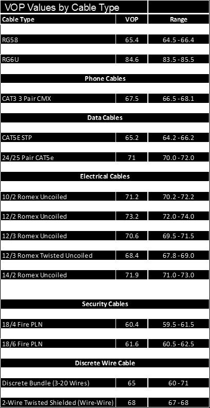
34 Cable Types and VOP To edit an existing cable, create a new cable, select the CABLE LIST button. This will display a cable list window as shown in the following screen. Add New Cable Type To create a new cable type select NEW. To change the name of the new cable select the text box and enter the name of the cable being created. Change the VOP to the correct VOP of the cable being tested. Appendix A of this manual contains typical cable types and VOP values Note: If the VOP is unknown see Calculate Unknown VOP section. The range for VOP is 0% - 99%. Edit Cable Properties To edit a current cable type, select EDIT. Select the cable to be edited from the library of cables. The details of the cable will be displayed in the window. Edit the cable name or VOP value as needed by selecting each field and changing them to fit proper cable properties. Select OK to save changes. 34
35 Calculate Unknown VOP If a cable is not found in the pre-populated list and the VOP is unknown or if the VOP of an existing cable is not accurate, calibration of the VOP may be necessary. A cable of known length 25ft 200 ft. is needed to calculate the VOP. Longer lengths (up to 500 ft.) will result in a more accurate VOP. Connect the known length of cable to the Mantis. From the main Mantis Application, select the Fault Location icon. Select TEST to perform a Fault Location test. If the result of the Fault Location test is greater than the known cable length, the VOP is set too high. If the length of the Fault Location test is less than the known cable length, the VOP is set too low. Use the calculation below as an example of how to determine the VOP for an unknown cable: VOP estimate = 84.6% Actual cable length = 30 feet Reported fault location = 38.5 feet VOP Actual = VOP Estimate* (Cable Length/Reported Fault Location) = (30/38.5) = 64.58% To create a new cable type with another VOP, select CABLE LIST then select NEW. To edit an existing cable, select a cable from the cable list then select EDIT. Enter or edit the cable name and VOP, then select OK. Run the Fault Location test with the new VOP and readjust until the length of the known cable is displayed or is very close. It may also be helpful and more accurate to use longer cables where possible, but a different test frequency will be necessary depending on the length of the cable and distance to fault. 35
36 File Management Save File(s) From the Fault Location test screen, select Save File in the upper right corner of the page. Enter a filename and select OK. This file will be saved to the Mantis unit, however the file is not viewable until it is transferred from the Mantis unit to the tablet. To transfer the file to the tablet, touch the back button to return to the main page or log back in to the Mantis Application. Select File Manager from the home screen. For intermittent test mode, swipe right to view files. Select Refresh at the top. Previously saved files will appear on a new page. Select any available file(s) to transfer to the tablet or check Select All. Select Copy Files option at the top of the page. When finished, a message appears Done Transferring Files at the bottom of the screen. Load File(s) From the Fault Location test screen, select Load File in the bottom left corner of the test page. Select the desired file from the available files on the tablet. Results will load immediately. 36
. Open the tablet s email program. Select the paper clip to to add an attachment. Select Select the folder labeled DCIM.")
37 File(s) In order to a file, a file manager must be installed on the tablet. An example of a file manager from Google Play Store is CHEETAH MOBILE, shown below. A test file must be saved on the tablet (see Save File section). Open the tablet s program. Select the paper clip to to add an attachment. Select Select the folder labeled DCIM. Inside this folder select LiveWire. All Fault Location test files are located in the fault_location folder. All Live Intermittent Fault Detection test files are located in the live_ifd folder. Select the proper folder and the file to be ed. The client will appear with an attachment in the . Input the Sender, Subject Line, and text as desired and select Send. 37
38 Interpreting Test Results The Mantis evaluates cable faults using SSTDR which is capable of detecting/locating/reporting both intermittent and hard cable faults. The Mantis transmits a small but recognizable signal along a pair of wires or cable which will reflect off impedance changes. When the reflection of this signal reaches the launch point, the distance to the impedance change is determined by the velocity of propagation (VOP), which is a characteristic of every cable. The table below displays the reflections that would be seen for both a short and open circuit fault. Type Launch Waveform with no detectable fault Waveform Short Circuit Fault Open Circuit Fault The waveform shape on the left is the initial start of the waveform, or location zero. This is the SSTDR signature that is caused by the cable connection. The waveform shapes shown to the right correspond to fault reflections. The behavior of up-down-up vs. down-up-down indicates a short or an open circuit, respectively. The time delay between the initial reflection (location = 0, where the Mantis is connected to the wire) and the reflection from the fault or end of the wire indicates the location of the fault. The time delay is converted to distance using VOP, which is why using the correct VOP for the type of cable is necessary an accurate measurement. The Mantis uses this information to display the distance and type of fault. For the Fault Location test mode, several different scans are sent down the cable and the optimum scan chosen. For Live Intermittent Fault Detection, continuous scans (single frequency) are used to monitor the cable for faults in real-time. 38

39 Fault Location Test: The Fault Location test shown below displays a short at the point where fault is indicated. The SSTDR signature can be seen at the beginning of the test and the short appears as an up-down-up reflection at some point during the scanning process. SSTDR Signature (Launch Pulse) Fault (Short) 39

40 To compare various frequencies tested, touch anywhere on the graph to view all of the simplified waveforms for each frequency used during the test. Touch and scroll up or down to view waveforms at the top or bottom of the list shown, then touch the waveform you wish to select for a full screen view of only that waveform by itself. Note: Any waveforms (among the full list) may be viewed, but the frequency that was chosen for final result during this test is the same waveform that was shown on the main Fault Location Test screen (and matches the distance to fault reading shown in text). 40

41 Waveform Analysis: The following waveform is an example of an Intermittent (IFD) test result, but the analysis can also be applied to the Fault Location waveforms. The buttons displayed at the bottom of the screen provide a legend for the graph and can be selected to provide a single graph or selection of graphs. The Reference graph displays the waveform of the transmitted signal and its reflections that are used as a reference for the wire scan with cables connected (known good state of the cable) before a fault is determined. The Focus graph displays the waveform (detected change; impedance signature) of the wire during a fault condition. The Difference graph displays the magnitude difference between the reference and focus graph (difference between the before/after states of the cable). The difference is used to determine the type of fault and its magnitude. In the above waveform, the fault and reference appear at the same place in this graph, because the fault (short) has occurred at the end of the cable. The reference is displaying at the end of the cable, and the fault is also displayed at the same place. 41
42 User Settings Mantis Application (Log-in Page) The Mantis client list is accessed from the Mantis log-in menu and by selecting CLIENT LIST. This list is only for use in Wi-Fi Client or Wired Client modes. Note: Manual connection mode must be selected for the Client List to appear. It may be necessary to delete, edit, or create new clients at times depending on network configuration needs. The Device Client List displays Mantis clients on the same network or in range of the tablet. If only one Mantis is being used, there should only be one Mantis in the client list. To add a new client select NEW from the client list. Input the new client name and IP address information. To delete a client from the list, select DELETE in the menu and touch the client to be deleted. The client will immediately be deleted from the list. To edit a client in the list, select EDIT from the client list. The name of each Client on the list can be anything that helps identify each Mantis unit that will be connected to from the Android tablet. Input the new name and IP address information. If you are trying to connect to a Mantis that is currently in Access Point (AP) mode, select Direct Connection (on the left), then REFRESH (top right). Be sure to configure the tablet to be connected directly to the Mantis through Wi-Fi. 42
43 Settings menu To check or change the Mantis main configuration settings, first log in to the Mantis and from the Main menu page select SETTINGS at the top. Advanced Intermittent Test Settings Uncheck the box to use the default settings (simple mode). Under most test conditions, the default settings will work very well and it is not recommended to use Advanced Intermittent Test settings unless the user/technician has a solid understanding of changing these settings. Enter a checkmark in the box to enable Advanced Intermittent Test settings. This enables three sets of optional (advanced) settings: Custom, Short, and Long referring to cable length. Unit of Measure From the main Mantis Application menu, select SETTINGS. Select Unit of Measure. Select standard or metric units. Alert Language Select Alert Language (Default: English) Select English or Italian (Additional language support will be added as the need arises at no additional charge) Note: This only affects the language used for alerts generated by the Mantis and not any other screens, settings, or functions. 43
44 Device menu This menu is for changing the Host Name, Password, and Time Zone. Host Name and Password The Host Name is the name that Mantis uses to identify itself (Default: Mantis) and the password is the password used to log-in to the Mantis (Default: cdma2000). The Host Name may be changed to help identify one or more Mantis units and is contained in the notifications. Select Host Name to change the host name. Select password to change the password. Changing this will also increase security and help guard against unauthorized use of your Mantis unit. Be sure to make note of these changes correctly before you apply the settings. Select APPLY SETTINGS. Mantis Time Zone Go to Device Settings. Select Time Zone. Scroll to the desired time zone and select it. Select APPLY SETTINGS. Select . Note that alerts are disabled by default and that most of the fields are grayed out. To enable alerts, check the empty box to the right of Disabled at the top. It changes to Enabled which enables the fields below it. Input User name, Password, SMTP Server, SMTP Port, and Authentication. These settings are for the account from which the Mantis sends all alerts. The example shown in the following screen shows valid settings for a Gmail account (except the username and password, which will need to be created by each user individually): 44
.")
45 When all fields are valid and correct, touch APPLY SETTINGS at the top. Touch VERIFY SETTINGS. This will authenticate all of the settings with the applicable server (in this case Google s Gmail server). Of course, this also requires the Mantis to have a valid connection to the internet. List An list can be added to send alerts to multiple members. Select NEW to create a new to receive alerts and input a valid address. Select EDIT or DELETE to edit or delete an . Check the box next to the s that will receive alerts. Select APPLY. 45
46 Mantis Software/Firmware Updates The Mantis software can be updated using the Mantis Android tablet application. Be sure that the Mantis has sufficient battery power (>20%) or connect the Mantis to the A/C to D/C power adapter. From the Mantis Session Log-in screen, select ABOUT. This dialog box shows only the current Android App version if you are not logged in to a Mantis unit. It shows all applicable software/firmware only if you are logged in to the Mantis. Close this window. Sign In to the Mantis. From the Main menu page select ABOUT in the top right corner of the page. Note the current Mantis Server version. Select Check Online (for this choice, the Mantis must be connected to a network with internet access). A confirmation dialog box opens: Okay to update? Select OK. A message pops up: Unit is updating, then Android tablet logs out. Wait for at least 2 minutes for the Mantis to update its firmware and reboot. Select the Sign In button to log back into the Mantis. Check software versions to ensure the Mantis has the latest Server App version. Alternate method (Update from file): From the Main menu page or the Log-in page, select ABOUT. Ensure the Android tablet has a valid internet connection. Select the Update button. The Android tablet downloads the latest Mantis Server App as indicated by the down arrow in the upper right corner of the screen. Once the download completes, the Download Information dialog box appears, saying Please use the Update from file button in the about section. Touch OK. Log-in to the Mantis from the log-in page. From the Main menu page select ABOUT. Note the current Mantis Server version. 46
47 From the Version Information dialog box, select the Update button. Select the Update from file button. This does not require the Mantis or the tablet to be connected to the internet, but requires that the Update file has been previously downloaded from the internet. The mantis_update.tar.gz file should appear under the Android tablet s download directory. Touch/select the file. A message pops up: Unit is updating, then Android tablet logs out. Wait for at least 2 minutes for the Mantis to update its firmware and reboot. Select the Sign In button to log back into the Mantis. Check software versions to ensure correctness. 47
48 WARNING! Disconnect all cables from the Mantis prior to cleaning. Failing to do so can damage the unit and result in personal injury. *Do not use abrasive, harsh cleaners, or solvents to clean the Mantis. Battery Maintenance The Mantis contains a rechargeable Lithium-ion battery. To charge the battery, plug the charger into the bottom port then plug the charger into the power source. Mantis battery is not user serviceable. NOTE: Lithium-ion batteries are hazardous waste and should be disposed of in compliance with local, state, and federal hazardous waste regulations. Cleaning Use a clean, damp cloth to clean the Mantis. Before cleaning, disconnect all cables from the Mantis. Failing to disconnect cables can damage the device and cause personal injury. Do not use harsh cleaners, abrasives, or solvents. Storage When not in use, store the Mantis in a temperature controlled area. Do not expose the Mantis to high temperatures or humidity. See the specifications section for Operating Environment limitations. 48
49 Specifications Specifications Description Size: 5.25 x 8.5 x 10.0 (with antenna) Physical Dimensions Power Supply Battery Voltage Warning 5.25 x 7.5 x 7.25 (without antenna) Weight: 2.25 lbs. (1.02 kg) Wall Adapter Voltage Input Range 10 to 28 VDC (12 V Nominal), 20W During power failure, battery will keep Mantis alive 3100 mah Totes Li-ion rechargeable Hours Typical, 4 hour typical charge cycle The Mantis is designed for use on cabling systems with voltage ratings: Output connector banana jacks rated CAT II 1000V/CAT III 600 V Measurement Method Spread Spectrum Time Domain Reflectometry (SSTDR) VOP Range 3-digit precision ranging from 20.0% to 99.9% +/- 2% accuracy for cables > 100 feet VOP Accuracy Range Maximum Length +/- 2 feet for cables < 100 feet Note: Accuracy Range applies with known VOP and consistent cable parameters Up to 20,000 ft. (6 km.) maximum testable cable length Note: Maximum testable cable length varies with VOP and cable type. Contact LiveWire Innovation for cables beyond this length Operating temperature: -20 to 70 C ( -4 to 158 F) Operating Environment Storage temperature: -30 to 85 C (-22 to 185 F) Humidity: 10% to 90%, non-condensing Altitude: 6,500 ft. (2,000m) operating ANSI/ISA ( ) 2004 CAN/CSA-C22.2 No Designed to Meet (Pending) UL 6101B (2003) IEC/EN nd Edition for measurement Category II, 1000 V EMC EN WEEE Compliant 49

50 Appendix A 50
51 Contacting LiveWire Innovation, Inc. For technical information and customer support, please visit or send an to Contact Information: Customer Service Phone: Toll Free: Local: Address: LiveWire Innovation, Inc South Jordan Gateway, Suite A South Jordan, UT USA General Terms/ Software and End User License Agreement The sales of all LiveWire Innovation products shall be subject to LiveWire s General Terms and Software and End User License Agreement located at Returns Prior to returning any product to LiveWire Innovation, Inc., you must first request a Return Merchandise Authorization Number by contacting the Customer Service Department at 1(855) Note: Shipments will not be accepted without an RMA number which must be clearly marked on the shipping label. 51
52 Warranty LiveWire Mantis is covered by the Limited Product Warranty set forth in and subject to the terms, conditions, limitations and disclaimers set forth in LiveWire s General Terms, No further warranties either implied or express will apply, nor will responsibility for operation of this device be assumed by LiveWire Innovation. Product Registration Registering your Mantis allows you to access support information and receive product updates. Register your products on the LiveWire Innovation website: Disposal WEEE Compliant: Prior to disposal of this product, please contact LiveWire Innovation for proper disposal options. Patents/Intellectual Property LiveWire Mantis is the trademark of LiveWire Innovation, Inc. and is covered by one or more patents as described at 52


53 LiveWire Mantis TM User Manual (Android Tablet Interface Version) For technical information and customer support, please visit or send an to Contact Numbers: Toll Free: Local: Address: LiveWire Innovation, Inc South Jordan Gateway, Suite A South Jordan, UT USA
Snap ShotTM User Manual
 Snap ShotTM Fault Finding/Cable Length Measurement SSTDR User Manual Accurately finds cable length, impediments in the cable and conditions at the end of every wire in your data, power, or communications/video
Cable Prowler TM. User Manual. Full-Color Cable Testing and Report Management.
 Cable Prowler TM Full-Color Cable Testing and Report Management User Manual Displays length measurement for each pair in feet or meters using TDR technology Detects presence of PoE and class of PoE per
Single cable multiswich programmer PC102W
 Single cable multiswich programmer PC102W 1. Product description The PC102W - single cable multiswich programmer (in the text - programmer) is useful instrument while configuring and troubleshooting SAT
OPERATING INSTRUCTIONS TOM-0431IP
 OPERATING INSTRUCTIONS TOM-0431IP Table of Contents FCC Information -------------------------------------------------------------------- 2 Safety and Environmental Precautions ------------------------------------------------
Cable Prowler TM. User Manual. Full-Color Cable Testing and Report Management
 Cable Prowler TM User Manual Full-Color Cable Testing and Report Management Displays length measurement for each pair in feet or meters using TDR technology Detects presence of PoE and class of PoE per
E-MANUAL. Thank you for purchasing this Samsung product. To receive more complete service, please register your product at.
 E-MANUAL Thank you for purchasing this Samsung product. To receive more complete service, please register your product at www.samsung.com/register Model Serial No. Contents Connecting Antenna and External
BY-HPE11KTA. Operating Instructions. Coaxial - LAN Converter with PoE function. Indoor Use Only. Model No. Attached Installation Guide
 Operating Instructions Coaxial - LAN Converter with PoE function Model No. Indoor Use Only BY-HPE11KTA Attached Installation Guide Before attempting to connect or operate this product, please read these
AudioFetch User Manual 1
 AudioFetch User Manual 1 Thank you for your purchase of: By Broadcastvision Entertainment The dynamic AudioFetch system enables Android and Apple smartphones and tablets with the AudioFetch App to receive
E-MANUAL. Thank you for purchasing this Samsung product. To receive more complete service, please register your product at.
 E-MANUAL Thank you for purchasing this Samsung product. To receive more complete service, please register your product at www.samsung.com/register Model Serial No. Contents Connecting Antenna and External
Dell Wyse 5030 PCoIP Zero Client
 Dell Wyse 5030 PCoIP Zero Client User Guide Regulatory Model: PxN Regulatory Type: PxN001 Notes, cautions, and warnings NOTE: A NOTE indicates important information that helps you make better use of your
Installation Guide. Wireless Display Receiver
 Wireless Display Receiver Installation Guide Model# SBWD950A This Installation Guide will walk you through the easy steps to set up your ScreenBeam Pro Wireless Display Receiver - Enterprise Edition. During
MANAGERS REFERENCE GUIDE FOR
 MANAGERS REFERENCE GUIDE FOR Receive Components/Supplies Device (Scanner) Set Up Access Point Routers Set up Scanners Scanner Functions Additional Scanner Functions - Menu Button - Function Descriptions
JD725A Cable and Antenna Analyzer - Dual Port
 COMMUNICATIONS TEST & MEASUREMENT SOLUTIONS JD725A Cable and Antenna Analyzer - Dual Port Key Features Portable and lightweight handheld instrument Built-in wireless frequency bands as well as the most
Video Extender DS128 DSRXL. Instruction Manual. 8-Port Cat5 VGA Digital Signage Broadcaster with RS232 and Audio
 DS128 DSRXL Instruction Manual Video Extender 8-Port Cat5 VGA Digital Signage Broadcaster with RS232 and Audio Cat5 VGA Digital Signage Receiver with RS232 and Audio FCC Compliance Statement This equipment
User Guide. MonitorMix User Guide 1
 User Guide EN MonitorMix User Guide 1 Introduction Thank you for downloading MonitorMix app for ios or Android. With MonitorMix, you can control MIX/MATRIX/AUX mixes wirelessly for your CL, QL or TF series
Operating Instructions
 Marshall Electronics Broadcast A/V Division Model No. VSW-2200 4-Input Seamless SDI A/V Switcher Operating Instructions Table of Contents 1. Overview... 2. Features.... Package Contents... 4. Specifications...
USER GUIDE 3. For more information visit
 USER GUIDE 3 For more information visit www.caldigit.com Table of Contents Section 1 : General Information Introduction 3 General Use Warnings 3 Safety Warnings 3 System Requirements 4 In the Box 4 TS3
E-MANUAL. Thank you for purchasing this Samsung product. To receive more complete service, please register your product at.
 E-MANUAL Thank you for purchasing this Samsung product. To receive more complete service, please register your product at www.samsung.com/register Model Serial No. Contents Quick Guides Using Smart Hub
AW900mT. User s Manual. Point-to-multipoint. Industrial-grade, ultra-long-range 900 MHz non-line-of-sight wireless Ethernet systems
 User s Manual Point-to-multipoint Industrial-grade, ultra-long-range 900 MHz non-line-of-sight wireless Ethernet systems User s Manual Non-line-of-sight :: 900 MHz Thank you for your purchase of the multipoint
DDW36C Advanced Wireless Gateway - Safety and Installation Product Insert. Federal Communications Commission (FCC) Interference Statement
 Interference Statement") DDW36C Advanced Wireless Gateway - Safety and Installation Product Insert Federal Communications Commission (FCC) Interference Statement This equipment has been tested and found to comply with the limits
DDW36C Advanced Wireless Gateway - Safety and Installation Product Insert Federal Communications Commission (FCC) Interference Statement This equipment has been tested and found to comply with the limits
THD601DC Set-top box
 THD601DC Set-top box Contents 1. Safety... 1 2. Appearance... 2 3. Rear Panel Connection... 3 4. Remote... 4 5 First Time Set-Up... 7 6. Network Settings... 8 6.1 Available Networks and Checking Current
Operation Guide Version 2.0, December 2016
 Operation Guide Version 2.0, December 2016 Document Revision History Revision Date Description v1.0 January 8, 2016 Initial release of COLR Operation Manual, based on firmware version 1.0.1 CONTENTS Contents...
FS3. Quick Start Guide. Overview. FS3 Control
 FS3 Quick Start Guide Overview The new FS3 combines AJA's industry-proven frame synchronization with high-quality 4K up-conversion technology to seamlessly integrate SD and HD signals into 4K workflows.
AEROTRAK PORTABLE AIRBORNE PARTICLE COUNTER MODEL 9110 QUICK START GUIDE
 AEROTRAK PORTABLE AIRBORNE PARTICLE COUNTER MODEL 9110 QUICK START GUIDE Thank you for purchasing a TSI AeroTrak Model 9110 Portable Airborne Particle Counter (particle counter). This guide will help you
Be sure to run the vehicle engine while using this unit to avoid battery exhaustion.
 CAUTION: TO REDUCE THE RISK OF ELECTRIC SHOCK DO NOT REMOVE COVER (OR BACK) NO USER-SERVICEABLE PARTS INSIDE REFER SERVICING TO QUALIFIED SERVICE PERSONNE; Please Read all of these instructions regarding
Operation Guide Version 1.0, December 2015
 Operation Guide Version 1.0, December 2015 Document Revision History Revision Date Description v1.0 January 8, 2016 Initial release of COLR Operation Manual, based on firmware version 1.0.1 CONTENTS Contents...
INFORMATION TO USER CAUTION RISK OF ELECTRIC SHOCK, DO NOT OPEN
 INFORMATION TO USER CAUTION RISK OF ELECTRIC SHOCK, DO NOT OPEN! CAUTION: TO REDUCE THE RISK OF ELECTRIC SHOCK, DO NOT REMOVE COVER (OR BACK). NO USER SERVICEABLE PARTS INSIDE. REFER SERVICING TO QUALIFIED
Lite USER GUIDE. 3 Lite. For more information visit
 USER GUIDE Lite 3 Lite For more information visit www.caldigit.com Table of Contents Section 1 : General Information Introduction 3 General Use Warnings 3 Safety Warnings 3 System Requirements 4 In the
22" Touchscreen LED Monitor USER'S GUIDE
 22" Touchscreen LED Monitor USER'S GUIDE Content Operation Instructions...1 Unpacking Instructions...2 Safety Precautions...2 Front View of the Product...3 Rear View of the Product...4 Quick Installation...5
Remote Control. degraded, causing unreliable operation. The recommended effective distance for remote operation is about 16 feet (5 meters).
.") Media Streaming Sound Bar RTS736W User Manual Remote Control using the remote control Point the remote control at the REMOTE SENSOR located on the unit (see Front Panel illustration for precise location).
Media Streaming Sound Bar RTS736W User Manual Remote Control using the remote control Point the remote control at the REMOTE SENSOR located on the unit (see Front Panel illustration for precise location).
Quick Start. RSHS1000 Series Handheld Digital Oscilloscope
 Quick Start RSHS1000 Series Handheld Digital Oscilloscope General Safety Summary Carefully read the following safety precautions to avoid personal injury and prevent damage to the instrument or any products
Redcare signal strength tester user manual.
 Redcare signal strength tester user manual. Page 1 Issue Apr 2012 Product description. The redcare GSM/GPRS Signal Strength Tester has been developed to help Security and Fire Alarm installers or engineers
Getting started with
 Getting started with Electricity consumption monitoring single phase for homes and some smaller light commercial premises OVERVIEW: The OWL Intuition-e electricity monitoring system comprises of three
LedSet User s Manual V Official website: 1 /
 LedSet User s Manual V2.6.1 1 / 42 20171123 Contents 1. Interface... 3 1.1. Option Menu... 4 1.1.1. Screen Configuration... 4 1.1.1.1. Instruction to Sender/ Receiver/ Display Connection... 4 1.1.1.2.
QUICK START GUIDE QT ANALOG HD CAMERA & DVR BUNDLE ENGLISH
 QUICK START GUIDE QT ANALOG HD CAMERA & DVR BUNDLE ENGLISH Table of Contents Welcome What s Included...3 Understanding your DVR...4 Get Connected Registration...5 Connect Your Cameras...5 Connect DVR to
VIDEO GRABBER. DisplayPort. User Manual
 VIDEO GRABBER DisplayPort User Manual Version Date Description Author 1.0 2016.03.02 New document MM 1.1 2016.11.02 Revised to match 1.5 device firmware version MM 1.2 2019.11.28 Drawings changes MM 2
AudioFetch User Manual 1
 AudioFetch User Manual 1 Thank you for your purchase of: By Broadcastvision Entertainment The dynamic AudioFetch system enables Android and Apple smartphones and tablets with the AudioFetch App to receive
Wireless Cloud Camera TV-IP751WC (v1.0r)
") TRENDnet s, model, takes the work out of viewing video over the internet. Previously to view video remotely, users needed to perform many complicated and time consuming steps: such as signing up for a
TRENDnet s, model, takes the work out of viewing video over the internet. Previously to view video remotely, users needed to perform many complicated and time consuming steps: such as signing up for a
EdgeConnect Module Quick Start Guide ITERIS INNOVATION FOR BETTER MOBILITY
 EdgeConnect Module Quick Start Guide ITERIS INNOVATION FOR BETTER MOBILITY 493456301 Rev B April 2009 Table of Contents Installation... 1 Setup... 2 Operation... 4 Live Video... 4 Video Settings... 5 Network
QUICK START GUIDE. IP Camera & NVR Bundle ENGLISH
 QUICK START GUIDE IP Camera & NVR Bundle ENGLISH Table of Contents Welcome What s Included...3 Understanding Your NVR...4 Get Connected Registration...5 Connect Your Cameras...5 Connect Your NVR...6 Powering
Description. Specifications and Ordering Information 1900/27 Vibration Monitor
 R Specifications and Ordering Information 1900/27 Vibration Monitor Description The 1900/27 is a single-channel, stand-alone, locally mounted vibration monitor. It can be used as a stand-alone machinery
Wireless Studio. User s Guide Version 5.1x Before using this software, please read this manual thoroughly and retain it for future reference.
 4-743-161-12 (1) Wireless Studio User s Guide Version 5.1x Before using this software, please read this manual thoroughly and retain it for future reference. DWR-R01D/R02D/R02DN/R03D 2018 Sony Corporation
E-MANUAL. Thank you for purchasing this Samsung product. To receive more complete service, please register your product at.
 E-MANUAL Thank you for purchasing this Samsung product. To receive more complete service, please register your product at www.samsung.com/register Model Serial No. Contents Connecting Antenna and External
LA1500R USER S GUIDE.
 LA1500R USER S GUIDE www.planar.com The information contained in this document is subject to change without notice. This document contains proprietary information that is protected by copyright. All rights
E-MANUAL. Thank you for purchasing this Samsung product. To receive more complete service, please register your product at.
 E-MANUAL Thank you for purchasing this Samsung product. To receive more complete service, please register your product at www.samsung.com/register Model Serial No. Contents Quick Guides Connecting the
imso-104 Manual Revised August 5, 2011
 imso-104 Manual Revised August 5, 2011 Section 1 Getting Started SAFETY 1.10 Quickstart Guide 1.20 SAFETY 1.30 Compatibility 1.31 Hardware 1.32 Software Section 2 How it works 2.10 Menus 2.20 Analog Channel
Package Contents. LED Protocols Supported. Safety Information. Physical Dimensions
 Pixel Triton Table of Contents Package Contents... 1 Safety Information... 1 LED Protocols Supported... 1 Physical Dimensions... 1 Software Features... 2 LED Status... 2 Power... 2 Activity LED... 2 Link
MATE3 Owner s Manual Addendum
 Purpose MATE3 Owner s Manual Addendum This document is an addendum to 900-0117-01-00, Revision C of the MATE3 System Display and Controller Owner s Manual. It provides descriptions of changes to the MATE3
E-MANUAL. Thank you for purchasing this Samsung product. To receive more complete service, please register your product at.
 E-MANUAL Thank you for purchasing this Samsung product. To receive more complete service, please register your product at www.samsung.com/register Model Serial No. Contents Quick Guides Connecting the
VAD Mobile Wireless. OBD-II User's Manual Version 1.0
 VAD Mobile Wireless OBD-II User's Manual Version 1.0 Table of Contents What Is VAD Mobile Wireless?... 1 What is the OBD-II Module?... 1 Where to Get a VAD Mobile Wireless System... 1 Installing the OBD-II
FS1-X. Quick Start Guide. Overview. Frame Rate Conversion Option. Two Video Processors. Two Operating Modes
 FS1-X Quick Start Guide Overview Matching up and synchronizing disparate video and audio formats is a critical part of any broadcast, mobile or post-production environment. Within its compact 1RU chassis,
Model#: IN-MDRI3MF. Hardware User Manual. 3MP Indoor Mini Dome with Basic WDR, Fixed lens. (PoE) Ver. 2013/02/04
 Ver. 2013/02/04") Model#: IN-MDRI3MF 3MP Indoor Mini Dome with Basic WDR, Fixed lens Hardware User Manual (PoE) Ver. 2013/02/04 Table of Contents 0. Precautions 3 1. Introduction 4 Package Contents... 4 Features and Benefits...
Model#: IN-MDRI3MF 3MP Indoor Mini Dome with Basic WDR, Fixed lens Hardware User Manual (PoE) Ver. 2013/02/04 Table of Contents 0. Precautions 3 1. Introduction 4 Package Contents... 4 Features and Benefits...
SELF-INSTALLATION GUIDE
 SELF-INSTALLATION GUIDE Welcome to FrontierTV You are just a few quick connections away from the most amazing TV experience you ve ever had. The colors are stunning and the sound is astonishing. Just follow
V17. Quick Guide. Smart Media Player A new way to watch live TV & online entertainment
 V17 Quick Guide Smart Media Player A new way to watch live TV & online entertainment 4K Ultra HD IPTV Wi-Fi LAN Movies 2 x USB Product & Services Informations Most Beautiful Android System with support
Positive Attendance. Overview What is Positive Attendance? Who may use Positive Attendance? How does the Positive Attendance option work?
 Positive Attendance Overview What is Positive Attendance? Who may use Positive Attendance? How does the Positive Attendance option work? Setup Security Codes Absence Types Absence Reasons Attendance Periods/Bell
DISTRIBUTION AMPLIFIER
 MANUAL PART NUMBER: 400-0045-005 DA1907SX 1-IN, 2-OUT VGA/SVGA/XGA/UXGA DISTRIBUTION AMPLIFIER USER S GUIDE TABLE OF CONTENTS Page PRECAUTIONS / SAFETY WARNINGS... 2 GENERAL...2 GUIDELINES FOR RACK-MOUNTING...2
VF-STB IP Appliance User Guide
 VF-STB IP Appliance User Guide Copyright 2007 Video Furnace, Inc. All Rights Reserved. Copyright 2002-2007 Video Furnace, Inc. All Rights Reserved This document refers to the current published version
FS4 Quick Start Guide
 FS4 Quick Start Guide Overview FS4 is AJA s flagship frame synchronizer and converter, offering incredible versatility and connectivity in a sleek and compact 1RU frame for all your 4K/ UltraHD/2K/HD/SD
P XGA TFT Monitor. User s Manual
 P6151 15 XGA TFT Monitor User s Manual Disclaimers This manual has been carefully checked and believed to contain accurate information. Axiomtek Co., Ltd. assumes no responsibility for any infringements
SAT IF distribution system
 7. Technical specifications Type cs43 RF input frequency range pr. 50-350 MHz inputs number 4 level pr. 55...88 dbµv 60...93 dbµv symbol rate 3 45 Ms/s return loss/impedance > 0 db/75 Ω LNB powering/control
USER MANUAL. 27 Full HD Widescreen LED Monitor L27ADS
 USER MANUAL 27 Full HD Widescreen LED Monitor L27ADS TABLE OF CONTENTS 1 Getting Started 2 Control Panel/ Back Panel 3 On Screen Display 4 Technical Specs 5 Care & Maintenance 6 Troubleshooting 7 Safety
E-MANUAL. Thank you for purchasing this Samsung product. To receive more complete service, please register your product at.
 E-MANUAL Thank you for purchasing this Samsung product. To receive more complete service, please register your product at www.samsung.com/register Model Serial No. Contents Connecting Antenna and External
SKYPLAY-MX Installation and Operation Guide
 SKYPLAY-MX Installation and Operation Guide Rev 130412 Important Safety Instructions Please completely read and verify you understand all instructions in this manual before operating this equipment. Keep
USER MANUAL. 27 Full HD Widescreen LED Monitor L270E
 USER MANUAL 27 Full HD Widescreen LED Monitor L270E TABLE OF CONTENTS 1 Getting Started 2 Control Panel/ Back Panel 3 On Screen Display 4 Technical Specs 5 Care & Maintenance 6 Troubleshooting 7 Safety
Store Inventory Instruction Guide
 Store Inventory Instruction Guide Review Equipment & Supplies page 2 Set-Up Access Point page 6 Register Scanners page 8 Place Fixture Stickers/Enter Ranges page 10 Scanning Basics and Additional Keyboard
MS2540 Current Loop Receiver with RS485 Communication
 MS2540 Current Loop Receiver with RS485 Communication User Manual Metal Samples Company A Division of Alabama Specialty Products, Inc. 152 Metal Samples Rd., Munford, AL 36268 Phone: (256) 358 4202 Fax:
EM7580 TV Streamer powered by OpenELEC Kodi
 EM7580 TV Streamer powered by OpenELEC Kodi 2 ENGLISH EM7580 - TV streamer powered by OpenELEC Kodi Table of contents 1.0 Introduction... 2 1.1 Introduction TV streamer... 2 1.2 OpenELEC and Kodi introduction...
V pro8 QUICK START GUIDE
 QUICK START GUIDE Welcome to your V pro8 FIRST STEPS POWERING ON CONNECTING YOUR COMPUTER Thank you for buying the Lawo V pro8, a true high-quality product developed and manufactured in Rastatt, Germany.
VGA Extender over Single CAT 6 Cable with Audio Support. Model Extend both video and audio up to 1000 feet
 VGA Extender over Single CAT 6 Cable with Audio Support Model 103004 Extend both video and audio up to 1000 feet Utilize a Cat 6 cable instead of a bulky VGA cable Supports a local monitor and local speakers
First Time Setup Guide
 First Time Setup Guide www.exhibio.com 1.877.EXHIBIO (394.4246) Exhibio ST-200 Components & Accessories Standing Mount TV Tuner with Input Cable (USB 2.0 only) VESA Mount Over-the-Air Antenna Power Adapter
E-MANUAL. Thank you for purchasing this Samsung product. To receive more complete service, please register your product at.
 E-MANUAL Thank you for purchasing this Samsung product. To receive more complete service, please register your product at www.samsung.com/register Model Serial No. Contents Connecting Antenna and External
ULTRA-TRAC APL INSTRUCTION MANUAL. Read and understand instructions before use. Patented. 851 Transport Drive Valparaiso, IN
 ULTRA-TRAC APL A C O U S T I C P I P E L O C A T O R INSTRUCTION MANUAL Read and understand instructions before use. Patented MADE IN USA 851 Transport Drive Valparaiso, IN 46383-8432 Phone: 888 4SENSIT
HD Digital MPEG2 Encoder / QAM Modulator
 HD Digital MPEG2 Encoder / QAM Modulator HDMI In QAM Out series Get Going Guide ZvPro 800 Series is a one or two-channel unencrypted HDMI-to-QAM MPEG 2 Encoder / QAM Modulator, all in a compact package
Installation Guide. Cellular Plug-in for Inverters with SetApp. Version 1.1
 Installation Guide Cellular Plug-in for Inverters with SetApp Version 1.1 2 Version History Version 1.0 (initial release)- January 2019 Version 1.1- January 2019 Modified Technical Specifications modem
PL2410W LCD Monitor USER'S GUIDE.
 PL2410W LCD Monitor USER'S GUIDE www.planar.com Content Operation Instructions...1 Safety Precautions...2 First Setup...3 Front View of the Product...4 Rear View of the Product...5 Quick Installation...6
E-MANUAL. Thank you for purchasing this Samsung product. To receive more complete service, please register your product at.
 E-MANUAL Thank you for purchasing this Samsung product. To receive more complete service, please register your product at www.samsung.com/register Model Serial No. Contents Connecting Antenna and External
Contents. Quick Guides. Connections. Remote Control and Peripherals. Connecting a Mobile Device. Using Smart Hub
 SMART TV E-Manual Contents Quick Guides Using Smart Hub 1 Connecting to the Internet 1 Setting up Smart Hub 1 Using Smart Hub Using the Samsung Smart Remote 2 Operating the TV with the POINTER button 3
GV-3D People Counter 3DPCV10-A
 GV-3D People Counter User's Manual Before attempting to connect or operate this product, please read these instructions carefully and save this manual for future use. 3DPCV10-A 2013 GeoVision, Inc. All
-TECH DIGITAL. Explore The High DefinitionWorld. Website: Hot Line: [US] USER MANUAL
![-TECH DIGITAL. Explore The High DefinitionWorld. Website: Hot Line: [US] USER MANUAL](/thumbs/80/80689593.jpg "-TECH DIGITAL. Explore The High DefinitionWorld. Website: Hot Line: [US] USER MANUAL") -TECH DIGITAL Explore The High DefinitionWorld Website: www.jtechdigital.com Hot Line: 1-888-610-2818[US] USER MANUAL J-Tech Digital ProAV H.264 Encoder/Decoder Many to Many HDMI Extender RoHS 1 Operating
-TECH DIGITAL Explore The High DefinitionWorld Website: www.jtechdigital.com Hot Line: 1-888-610-2818[US] USER MANUAL J-Tech Digital ProAV H.264 Encoder/Decoder Many to Many HDMI Extender RoHS 1 Operating
IMPORTANT! This instruction guide explains how to install your CCTV system.
 IMPORTANT! This instruction guide explains how to install your CCTV system. Which accessories do you need before getting started? 1. Monitor or TV (recommended not less than 19" for clear viewing) 2. HDMI
HD-1603 Single Input MPEG-4 DVB-T HD Encoder/Modulator User Guide and Install Manual
 ZyCastR digi-mod HD Range digi-mod HD-1603 www.digi-modbyzycast.com HD-1603 Single Input MPEG-4 DVB-T HD Encoder/Modulator User Guide and Install Manual Table of Contents www.digi-modbyzycast.com Safety
E-MANUAL. Thank you for purchasing this Samsung product. To receive more complete service, please register your product at. Model Serial No.
 E-MANUAL Thank you for purchasing this Samsung product. To receive more complete service, please register your product at www.samsung.com Model Serial No. To directly go to the page that provides instructions
QUICK START GUIDE. QT Analog HD Camera & DVR Bundle ENGLISH
 QUICK START GUIDE QT Analog HD Camera & DVR Bundle ENGLISH Table of Contents Welcome What s Included...3 Understanding your DVR...4 Get Connected Registration...5 Connect Your Cameras...5 Connect DVR to
Contents: 1 LANsmart Pro Main Unit 4 Remote Unit: ID1, ID2, ID3, ID4
 LANsmart Pro user manual Introduction LANsmart Pro is a hand-held, multifunction Cable Map Tester and Cable Length Meter. It has an integrated Analog and Digital Tone Generator, Port Finder, and Quick
ST8-WiFi Timer. Installation Guide and Operations Manual. English MIN M D YYYY
 ST8-WiFi Timer Installation Guide and Operations Manual AM M D YYYY English Contents ST8-WiFi Timer Installation Guide and Operations Manual Introduction Welcome to Rain Bird... 1 Timer Features... 1 Controls
IP LIVE PRODUCTION UNIT NXL-IP55
 IP LIVE PRODUCTION UNIT NXL-IP55 OPERATION MANUAL 1st Edition (Revised 2) [English] Table of Contents Overview...3 Features... 3 Transmittable Signals... 3 Supported Networks... 3 System Configuration
E-MANUAL. Thank you for purchasing this Samsung product. To receive more complete service, please register your product at.
 E-MANUAL Thank you for purchasing this Samsung product. To receive more complete service, please register your product at www.samsung.com/register Model Serial No. Contents Quick Guides Connecting the
BRIGHTLINK HDMI EXTENDER OVER ETHERNET - H METER MODEL: BL-EXT-IP-264
 BRIGHTLINK HDMI EXTENDER OVER ETHERNET - H.264-120 METER MODEL: BL-EXT-IP-264 Operating Instructions BRIGHTLINKAV.COM 1 Introduction This HDMI over IP Extender use the advanced H.264 as the compression
User Manual PS-684. HDBaseT Extender Kit 70m. All Rights Reserved. Version: UHBT70P_2016V1.2
 User Manual PS-684 All Rights Reserved Version: UHBT70P_2016V1.2 Preface Read this user manual carefully before using this product. Pictures shown in this manual is for reference only, different model
USER MANUAL. VP-435 Component / UXGA HDMI Scaler MODEL: P/N: Rev 13
 KRAMER ELECTRONICS LTD. USER MANUAL MODEL: VP-435 Component / UXGA HDMI Scaler P/N: 2900-000262 Rev 13 Contents 1 Introduction 1 2 Getting Started 2 2.1 Achieving the Best Performance 2 2.2 Safety Instructions
Overview. Shipped in the Venue Vizion Package: Simplified Integration Process. Installation consists of 6 easy steps:
 Overview Shipped in the Venue Vizion Package: Four two-channel QMOD Encoder-Modulators Each unit can accept up to 2 inputs, providing up to 8 channels in the system. One ICE-HE-DXL Display Control Center
DVISm. DVISm - Mini Digital Video Insertion System. Quick Start Guide. Patent Pending
 DVISm Patent Pending DVISm - Mini Digital Video Insertion System Quick Start Guide Although every effort has been taken to ensure the accuracy of this document it may be necessary, without notice, to make
INSTALLATION MANUAL FT-FOTR-1VDE-ST-S
 INSTALLATION MANUAL FT-FOTR-1VDE-ST-S 1-Channel Digital Duplex Baseband Video Transmitter and Receiver With Reverse Data Transmission & Ethernet Transmission v1.0 4/5/11 1 PACKAGE CONTENTS This package
G4500. Portable Power Quality Analyser. Energy Efficiency through power quality
 G4500 Portable Power Quality Analyser Energy Efficiency through power quality The BlackBox portable series power quality analyser takes power quality monitoring to a whole new level by using the revolutionary
E-MANUAL. Thank you for purchasing this Samsung product. To receive more complete service, please register your product at.
 E-MANUAL Thank you for purchasing this Samsung product. To receive more complete service, please register your product at www.samsung.com/register Model Serial No. Contents Quick Guides Connecting the
USER MANUAL Full HD Widescreen LED Monitor L215ADS
 USER MANUAL 21.5 Full HD Widescreen LED Monitor L215ADS TABLE OF CONTENTS 1 Getting Started 2 Control Panel/ Back Panel 3 On Screen Display 4 Technical Specs 5 Care & Maintenance 6 Troubleshooting 7 Safety
Peak Atlas IT. RJ45 Network Cable Analyser Model UTP05. Designed and manufactured with pride in the UK. User Guide
 GB05-7 Peak Atlas IT RJ45 Network Cable Analyser Model UTP05 Designed and manufactured with pride in the UK User Guide Peak Electronic Design Limited 2001/2013 In the interests of development, information
Transmitter Interface Program
 Transmitter Interface Program Operational Manual Version 3.0.4 1 Overview The transmitter interface software allows you to adjust configuration settings of your Max solid state transmitters. The following
Z-IP Stream 004/008. User Guide and Installation Manual. Four or Eight Input QAM Encoder / Modulator
 Z-IP Stream 004/008 User Guide and Installation Manual Four or Eight Input QAM Encoder / Modulator MPEG-2 / H.264 HD ENCODER with QAM /IP/ & ASI Outputs Contents Safety Precautions... 3 Package Contents...
MT300 Pico Broadcaster
 MT300 Pico Broadcaster Version 1.0 OPERATOR MANUAL 1 August 21, 2012 Table of Contents 1. PREFACE... 3 2. IMPORTANT NOTICE... 3 3. INTRODUCTION... 3 3.1 OVERVIEW... 3 3.2 DEFAULT SETTINGS... 4 3.3 GENERAL