SINGLE ZONE CLIMATE ZONING SYSTEM. Technical Manual. Polyaire Pty Ltd
|
|
|
- Henry Malone
- 6 years ago
- Views:
Transcription
1 SINGLE ZONE CLIMATE ZONING SYSTEM Technical Manual Polyaire Pty Ltd White Road GEPPS CROSS South Australia, 5094 Tel: (08) Fax: (08)
2
3 CONTENTS Features 1 Application 1 Components 2 Connection Diagram 3 Installation 3 Commissioning Instruction 5 1. Initiating and Exit Setting Process 5 2. Room Temperature Sensor 5 3. Minimum Ventilation 5 4. Damper on/off Test 6 Trouble Shooting Guide 6 User Manual 7 Programming Mode 8 Appendix A - Specifications 14 Appendix B - Single VAV Product Code 15 Liability Please read the instructions before installing this Zonemaster System. Polyaire Pty Ltd does not accept any responsibility for loss or damage that may occur as a result of the installation of this System.
4 FEATURES Manual and programmable zone temperature control. Maintains room temperature within ±1 C using an onboard sensor. LCD indicator for zone status and parameter display. User-friendly temperature and program setting. Real time clock with battery backup programmable temperature setting and start time. Returns to last setting after power drop. Programmable minimum ventilation. Max (or fully open) control. APPLICATION Zonemaster single VAV system is a fully featured and engineered system that is well suited to all ducted, reverse cycle, heating and evaporative air conditioning systems for light commercial, residential or apartment applications. It is especially designed for an area with dynamic heat loads, and where a constant or exact temperature is required. Page 1

5 9) Central Latch Adaptor (Only if 2 motors are used) Connects the Triple Centre Latched Adaptor with the damper motors.
6 CONNECTION DIAGRAM The cabling of the Zonemaster single VAV system is straightforward. The touchpad connects the damper motor and power supply in serial via an adaptor, and the temperature sensor can be plugged into the socket on the back of the touchpad, as shown in Figure 1. Yellow Damper Motor Figure 1. Wiring Diagram - One Motor Figure 2. Wiring Diagram - Two Motors Figure 1. Wiring Diagram INSTALLATION 1) Plug the 24VAC power supply into the power-in port and a pre-tested control cable into the touchpad port in the adaptor. Plug the adaptor into the damper. Warning - Zonemaster components are not compatible with other motors. Page 3
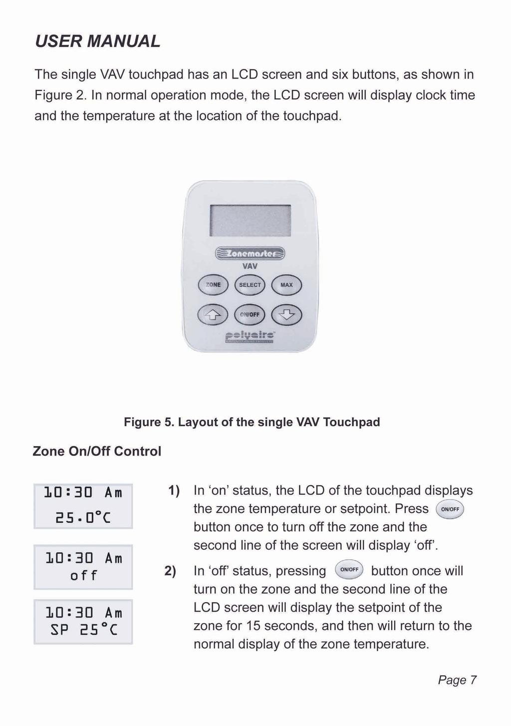
7

 At the setting mode, pressing button at any time will return to the normal operation mode. 2.")

 At the setting mode, press button until the LCD displays the Sensor screen. 3)")
8 COMMISSIONING INSTRUCTION The Zonemaster single VAV has two parameters, room temperature and minimum ventilation, that should be set in the commissioning stage. 1. Initiating and Exit Setting Process 1) Hold down both and buttons for about 5 seconds until the LCD displays Setting on the top line of the LCD screen. 2) At the setting mode, pressing button at any time will return to the normal operation mode. 2. Room Temperature Sensor The touchpad has an onboard sensor for temperature control. The sensor can be calibrated to provide more accurate temperature control as follows. 1) Using an accurate probe to measure the temperature of the area you want to calibrate and record the value. 2) At the setting mode, press button until the LCD displays the Sensor screen. 3) Press or button to adjust the displayed value to the value recorded. 3. Minimum Ventilation Customers may prefer minimum ventilation during the climate control. This ventilation allows a minimum airflow into the zone that is switched on. The amount of ventilation can be set from 0 to 30% open with a default of 0%. 1) At the setting mode, press button until the LCD displays the Min Vent screen. 2) Press or button to adjust the percent value of the minimum ventilation as desired. Page 5
9 4. Damper on/off Test 1) Switch on the air conditioner. 2) Press button to turn the zone on or off to check if the damper is correctly connected by feeling the air at the outlet. Refer to User s manual for the operation. TROUBLE SHOOTING GUIDE Problem Nothing is showing on touchpad LCD. Touchpad display is not normal. No response from dampers when turning on or off. Temperature is beyond ±1 C range. Suggested Action Check the power supply. Check the cable and plug to the touchpad. First disconnect the battery. Reset the touchpad by turning the power supply off and on. If the display is normal, plug in the battery again. Check the connection between the touchpad and the damper motor. Check the 24V AC power supply. Air Conditioner does not have enough capacity for the area. Too much air coming from other areas. Please contact distributors for any other problems not listed as above. Page 6
10 3. 3.
 Press or button again to adjust the setpoint to the desired value. 3) The screen will return to zone temperature display in 15 seconds with no key being pressed.")

11 Zone Temperature Setting Maximum Damper 1) In on status, press or button once to allow the setpoint of the zone to be displayed on the second line of the LCD. 2) Press or button again to adjust the setpoint to the desired value. 3) The screen will return to zone temperature display in 15 seconds with no key being pressed. 1) Press button once, the barrel damper will be fully opened and the screen will display MAX on the second line. 2) In MAX status, press button again to return to the normal operation mode. Programming Mode Programmable zone temperature control is an important feature of the Zonemaster single VAV system. This system has a program capability which means the system has an individual program for weekdays (Monday to Friday), Saturday and Sunday respectively. Each program has 4 programmable events per day: Wake, Day, Back and Sleep, which can be turned on or off individually. For these events, the user can adjust the start times and the cooling/heating temperature setting. In order to use the program, the user has to enable the program during the setup. The Zonemaster single VAV system provides a battery backup real time clock to support the programming mode. The program is set in default mode from the factory with the settings listed in the following table. Page 8
12 Program Wake Day Back Sleep Monday to Friday Saturday Sunday Start time 6.30AM 8.00AM 5.30PM 10.00PM Set cool 24 C off 24 C 30 C Set heat 21 C off 21 C 17 C Start time 7.30AM 12.30PM 6.00PM 11.30PM Set cool 24 C 24 C 24 C 30 C Set heat 21 C 21 C 21 C 17 C Start time 7.30AM 12.30PM 6.00PM 11.30PM Set cool 24 C 24 C 24 C 30 C Set heat 21 C 21 C 21 C 17 C The above default settings are explained as follows; Monday to Friday: 6:30AM Wake, the zone turns on with a setpoint of 24 C for cooling mode and 21 C for heating mode. 8:00AM Day, the zone turns off. 5:30PM Back, the zone turns on again with a setpoint of 24 C for cooling mode, and 21 C for heating mode. 10:00PM Sleep, the zone s temperature setpoint is set to 30 C for cooling mode and 17 C for heating mode. Page 9

13 Saturday: 7:30AM Wake, the zone turns on with a setpoint of 24 C for cooling mode and 21 C for heating mode. 12:30PM Day, the zone s temperature setpoint is set to 24 C for cooling mode and 21 C for heating mode. 6:00PM Back, the zone s temperature setpoint is set to 24 C for cooling mode and 21 C for heating mode PM Sleep, the zone s temperature setpoint is set to 30 C for cooling mode and 17 C for heating mode. Sunday: The program is the same as Saturday s. Setting Clock and Week 1) Press button once to select the clock and week setting. 2) Use or button to change the flashing hours to the desired value. 3) Press button once more to select the minutes to be flashing. 4) Use or button to change the flashing minute to the desired value. 5) Press button again to select week to set. 6) Use or button to change the weekday to the desired day. 7) It will return to the normal operation mode itself in 15 seconds with no key being pressed. Page 10
 In enable status, pressing button will select each of the program data to be adjusted.")
14 Adjust Program Time 1) Press button twice, the LCD shows the program status. 2) Factory default status of the program is disabled that means no program control. Pressing button once will enable the program. 3) In enable status, pressing button will select each of the program data to be adjusted. At the first screen, it shows the start time of the Wake event of the program for Monday to Friday. 4) Use or button to change the flashing hours to the desired value. 5) Press button once to select minutes, and repeat step 4) to change the minutes. 6) If you do not want the event to happen press button to disable it. 7) Press button again, the LCD will show the temperature setpoint for cooling mode of the event. 8) Use or button to change the setpoint in cooling mode to the desired value or press button to turn off the zone at the start time in cooling mode. 9) Press button again, the LCD will show the temperature setpoint for heating mode of the event. 10) Use or button to change the setpoint in heating mode to the desired value or press button to turn off the zone at the start time in heating mode. Page 11
 Follow step 4) to 10) to set the start time and cooling/heating setpoint of Day event or disable the event.")
15 11) Press button again, the LCD will show the start time of the Day event of the program for Monday to Friday. 12) Follow step 4) to 10) to set the start time and cooling/heating setpoint of Day event or disable the event. 13) Press button again, the LCD will show the start time of the Back event of the program for Monday to Friday. 14) Follow step 4) to 10) to set the start time and cooling/heating setpoint of Back event or disable the event. 15) Press button again, the LCD will show the start time of the Sleep event of the program for Monday to Friday. 16) Follow steps 4) to 10) to set the start time and cooling/heating setpoint of Sleep event or disable the event. 17) Follow steps 3) to 16) to adjust the Saturday program. 18) Follow steps 3) to 16) to adjust the Sunday program. 19) It will return to the normal operation mode itself in 15 seconds with no key being pressed. Page 12
16 Programming Information Sheet The following program tables are designed to assist the user in programming. Program Wake Day Back Sleep Monday to Friday Saturday Sunday Start time Set cool Set heat Start time Set cool Set heat Start time Set cool Set heat Page 13
17 APPENDIX A - TECHNICAL SPECIFICATIONS Environmental Requirements Operating temperature 0 C to 60 C Altitude 0 to 2000 metres Operating relative humidity 10% to 80% Avoid static electricity hazards Avoid electromagnetic radiation sources Avoid dust contamination Avoid highly corrosive environments Touchpad Power input Power Consumption Touchpad Dimensions Normal Style Single VAV Slimline Single VAV Transformer Input Voltage Output Voltage Wattage 24VAC 50Hz 0.5 VA 78mm Wide x 118mm High x 13mm Deep 76mm Wide x 116mm High x 4mm Deep 240VAC, 50Hz 24VAC, 50Hz 24W Supply Air Sensor NTC type, 10kΩ at 25 C Battery AAAM rechargeable battery, 3.6V Page 14
18 APPENDIX B - SINGLE VAV PRODUCT CODE Code Items Description Zonemaster Single Zone VAV Single zone VAV touchpad (1) Rechargeable battery (1) Adaptor (1) Mounting bracket kit (1) Technical manual (1) Supply Air Sensor Supply air sensor with 7M lead NEAT 24V Transformer Plug 24V transformer with plug Control Cable 7M Pre-made control cable 7M Double Centre Latched Adaptor Adaptor 6P6C. Double Centre Latched (1) (ONLY IF 2 MOTORS ARE USED) Page 15
19
20 by
ZoneTouch V2 Zone Control System User Manual
 ZoneTouch V2 Zone Control System User Manual www.polyaire.com.au 2014 Polyaire Pty Ltd II ZONEMASTER ZONETOUCH V2 ZONE CONTROL SYSTEM - User Manual TABLE OF CONTENTS 1) Features 2 2) Wall Controller Layout
Weekly Time Switch. Rated time Time setting range Time division 24 hrs x 7 days 00:00 to 23:59 1min
 Weekly Time Switch Easy Programming with Large LCD Display and Interactive Functions Programming for 24 hrs x 7 days using just five switches. Sixteen program steps available. Power supply freely selectable
Omni Ultimate Quick Start Guide. 120V AC or 230V AC.
 Omni Ultimate Quick Start Guide 120V AC or 230V AC www.omnicharge.co POWER YOUR NEXT ADVENTURE For more information visit our support page at www.omnicharge.co 2 BEFORE USING CALIBRATE THE BATTERY To make
Environmental Conditions, page 2-1 Site-Specific Conditions, page 2-3 Physical Interfaces (I/O Ports), page 2-4 Internal LEDs, page 2-8
, page 2-4 Internal LEDs, page 2-8") 2 CHAPTER Revised November 24, 2010 Environmental Conditions, page 2-1 Site-Specific Conditions, page 2-3 Physical Interfaces (I/O Ports), page 2-4 Internal LEDs, page 2-8 DMP 4305G DMP 4310G DMP 4400G
2 CHAPTER Revised November 24, 2010 Environmental Conditions, page 2-1 Site-Specific Conditions, page 2-3 Physical Interfaces (I/O Ports), page 2-4 Internal LEDs, page 2-8 DMP 4305G DMP 4310G DMP 4400G
Stage Right Party 10-Watt Mini Beam Moving Head LED Light
 Stage Right Party 10-Watt Mini Beam Moving Head LED Light P/N 612980 User's Manual SAFETY WARNINGS AND GUIDELINES Please read this entire manual before using this device, paying extra attention to these
SAUTER flexotron RDT405 Manual
 SAUTER flexotron 400 - RDT405 Manual P100012100 Table of contents DISCLAIMER The information in this manual has been carefully checked and is believed to be correct. Fr. Sauter AG however, makes no warranties
Good Display Specifications
 Specifications Type: Model No. Description: 5.0inch TFT LCD module GD567M03-GTI050TN22 5.0 LCD with 640 x RGB x 480 dots Supports CVBS/Video & VGA input RoHS Compliant Prepared: Xiaoli Lan Checked: Moon
Inserting the batteries. Basic settings of the remote control
 Inserting the batteries Procedure prior to first use or when changing batteries Remove the back plate to expose the battery tray. Insert 2 x AA 1.5V alkaline batteries. Ensure the polarity of the batteries
Luminaire installation box Surface-mounted box Ceiling installation box
 -Smart PTM Ambient light sensor and motion detector for constant lighting control uminaire installation box Surface-mounted box Ceiling installation box Overview: -SMART PTM i is an ambient light sensor,
Innovative Air Systems ABN When Calling For Support Quote:.doc
 1.0 User Guide 1.1 Normal Display This displays the current time and date. 1.2 Condition On Press the button to turn on the air conditioning. If the After Hours Timer is set then the air conditioning
Comfort System T-32-P Universal Thermostat. Operation Manual
 TM Comfort System T-32-P Universal Thermostat TM O Operation Manual Your new Comfort System T-32-P Universal Thermostat has been built using the highest quality components and design currently available.
Weekly Timer. Mounting track 50 cm (1.64 ft) length PFP-50N 1 m (3.28 ft) length PFP-100N
 length PFP-50N 1 m (3.28 ft) length PFP-100N") Weekly Timer 1/4 DIN Size Timer Features Prompted Programming and Large LCD Display 24 hours x 7 days programming using just 5 switches 16 program steps and cycle operation Two independent 15 A control
Weekly Timer 1/4 DIN Size Timer Features Prompted Programming and Large LCD Display 24 hours x 7 days programming using just 5 switches 16 program steps and cycle operation Two independent 15 A control
NS-3 RF Noise Source Operation Manual
 RF Noise Source Operation Manual Version 2.04 June 3, 2016 SPECIFICATIONS Frequency... Maximum output level... Output flatness... (at max output level) Impedance... Displayed level... Repeatability...
Waterline Room Controller - Type WLCT3
 INSTRUCTIONS Introduction Room controller type WLCT3 is a 4-event programmable controller used to control areas with underfloor heating or special features of a WLM3 installation. The standard WLCT3 can
RT505TX Programmable. The RT505TX can be used with any of these receivers RXBC605 RXWBC605 RXVBC605 RXST MHz
 RT505TX T RT505 T505TX TX RT505TX RT505TX RT505TX 5TX Programmable Room o Thermostat RXBC605 RXRT505 RXWBC605 RXST625 RXVBC605 The RT505TX can be used with any of these receivers 868MHz RT505TX RT505TX
TP7001 Range Electronic 7 Day Programmable Room Thermostat. Danfoss Heating. Installation Guide
 TP7001 Range Electronic 7 Day Programmable Room Thermostat Danfoss Heating Installation Guide For a large print version of these instructions please call Marketing on 0845 121 7400. Certification Mark
Cronotermostato Digitale
 Cronotermostato Digitale CHRONOS KEY Manuale d Uso User Manual DIGITAL PROGRAMMABLE THERMOSTAT Index Dimensions Page 4 Connection diagram Page 4 Safety warnings Page 5 Technical specifications Page 6 Display
MP 35" Zero-G 100Hz Curved Monitor with AMD FreeSync 2.0
 MP 35" Zero-G 100Hz Curved Monitor with AMD FreeSync 2.0 P/N 31005 User's Manual SAFETY WARNINGS AND GUIDELINES Please read this entire manual before using this device, paying extra attention to these
MP Zero-G 27" WQHD 144Hz TN-LED Monitor with AMD FreeSync
 MP Zero-G 27" WQHD 144Hz TN-LED Monitor with AMD FreeSync P/N 31004 User's Manual SAFETY WARNINGS AND GUIDELINES Please read this entire manual before using this device, paying extra attention to these
28 4K LED monitor. User Manual M284K
 28 4K LED monitor User Manual M284K CONTENTS Safety Information... 2 What s included..... 4 Getting Started....... 8 Troubleshooting.... 14 Specification.... 15 2 of 15 SAFETY INFORMATION Read these instructions
Automatic Transfer Switch Control PLC Operator s Manual
 MTS Power Products MIAMI FL 33142 ATS-22AG Automatic Transfer Switch Control PLC Operator s Manual Dedicated Single Phase Transfer Switch ATS-22AG Automatic Transfer Switch INTRODUCTION 1.1 Preliminary
SCALE & WEIGHT DISPLAYS
 The MICRO SERIES SCALE & WEIGHT DISPLAYS LARGE DIGIT MODELS Mighty-5S DPM MODELS Micro-S & Mighty-1S Mighty-1S Micro-S ELECTRO-NUMERICS, INC. Introduction The Electro-Numerics family of Digital Panel Meters
P XGA TFT Monitor. User s Manual
 P6151 15 XGA TFT Monitor User s Manual Disclaimers This manual has been carefully checked and believed to contain accurate information. Axiomtek Co., Ltd. assumes no responsibility for any infringements
SINCE User Manual 7 DAY PROGRAMMABLE DIGITAL TIMER MODEL PS-100. The best solutions for automation and protection.
 SINCE 1973 User Manual 7 DAY PROGRAMMABLE DIGITAL TIMER MODEL PS-100 The best solutions for automation and protection www.nassarelectronics.com Description The PS-100 is a 7 day programmable digital timer
Installation and User Guide 458/CTR8 8-Channel Ballast Controller Module
 Installation and User Guide 458/CTR8 8-Channel Ballast Controller Module Helvar Data is subject to change without notice. www.helvar.com i Contents Section Page Introduction 1 Installation 2 1. Attach
RD RACK MOUNT DIMMER OWNERS MANUAL VERSION /09/2011
 RD - 122 RACK MOUNT DIMMER OWNERS MANUAL VERSION 1.3 03/09/2011 Page 2 of 14 TABLE OF CONTENTS UNIT DESCRIPTION AND FUNCTIONS 3 POWER REQUIREMENTS 3 INSTALLATION 3 PLACEMENT 3 POWER CONNECTIONS 3 OUTPUT
DLP200M 2 Relay Module for Heating and Cooling Plants
 Product Sheet TH6.24 Thermostat Type DLP200M DLP200M 2 Relay Module for Heating and Cooling Plants The DLP 200 M is a relay module for activation of loads (namely thermal actuators or circulators) in wireless
Operation Guide 6022 ENGLISH
 Operation Guide 6022 Control Panel Reset TEMP UP SET CLOCK PROG2 TIME SET Heat/Cool Mode Switch Fan Switch Target Temp TIME SLOT Time EPA PROGRAM COPY HOLD REVIEW FILTER TEMP DOWN Battery Compartment Statement
DDW36C Advanced Wireless Gateway - Safety and Installation Product Insert. Federal Communications Commission (FCC) Interference Statement
 Interference Statement") DDW36C Advanced Wireless Gateway - Safety and Installation Product Insert Federal Communications Commission (FCC) Interference Statement This equipment has been tested and found to comply with the limits
DDW36C Advanced Wireless Gateway - Safety and Installation Product Insert Federal Communications Commission (FCC) Interference Statement This equipment has been tested and found to comply with the limits
ACT 10 Digital Keypad Operating & Installation Instructions This manual is found at
 ACT 10 Digital Keypad Operating & Installation Instructions 18-00001 This manual is found at www.eaglesecuritysolutions.co.uk Installation Notes Always remember to factory default the controller before
BT Diverse Repeater. User Guide
 BT Diverse Repeater User Guide Section Welcome to your BT Diverse Repeater Range Extender Extends the range in which you can make and receive calls from your existing DECT base station by up to 50m indoors
TABLE OF CONTENTS Important Safety Instructions Package Content Setting Up the Display Trouble shooting Specifications Product Dimensions
 TABLE OF CONTENTS Important Safety Instructions...1 1.1 Safety precautions and maintenance....1 1.2 Use.......4 1.3 Installation Notes.......7 Package Content...9 2.1 Unpacking...9 2.2 Accessories......10
USER MANUEL. SNIPE 2 Ref R13
 USER MANUEL SNIPE 2 Ref. 0141317R13 Contents 1. General Information 1-1. Introduction 1-2. Proper use and operation 1-3. Safety notes......... 2 3 3 2. Contents 2-1. Accessory included 2-2. Name of parts......
Programmable Room Thermostat With RF
 Salus RT500RF Manual:89 10/7/10 23:43 Page 1 Programmable Room Thermostat With RF Instruction Manual Model No RT500RF 2 Salus RT500RF Manual:89 10/7/10 23:43 Page 2 PRODUCT COMPLIANCE This product complies
Installation Operation Maintenance
 Installation Operation Maintenance Rooftop Energy Recovery Module for TKD / TKH / WKD / WKH YKD / YKH / DKD / DKH # 125-155-175-200 250 265-290-340 # 275-300-350-400-500-600 April 2011 RT-SVX42B-E4 General
XTM72E & F Real-Time Clock Modules
 Capricorn Controls Ltd Data & Application Notes Page 1 of 8 XTM72E & F Real-Time Clock Modules Originally designed to compliment our wide range of Gen-Set controls, these DC powered Real-Time-Clocks have
Instruction Manual. Universal Flow Controller Model 261 / 261-EC-01
 Universal Flow Controller Model 261 / 261-EC-01 Instruction Manual Type ARS 261-EC 01 Art.-no: 82212264 Table of Contents 1. Safety Instructions 2. Product ID - Dimensions 3. Function Description 4. Installation
USER MANUAL. 27 Full HD Widescreen LED Monitor L270E
 USER MANUAL 27 Full HD Widescreen LED Monitor L270E TABLE OF CONTENTS 1 Getting Started 2 Control Panel/ Back Panel 3 On Screen Display 4 Technical Specs 5 Care & Maintenance 6 Troubleshooting 7 Safety
LCD Thermometer / Clock S No. 1253
 Installation and Operating Manual LCD Thermometer / Clock S No. 1253 The 3 fold thermometer with crystal clock is purpose build for the mounting in caravans, boats and intervention vehicles. Please read
Master Time Clock MTC Users Manual
 Master Time Clock MTC-6000 Users Manual Midwest Time Control Phone (972)987-4408 Toll Free (888)713-0373 FAX (877)720-9291 www.midwest-time.com sales@midwest-time.com TABLE OF CONTENTS TOPIC PAGE GENERAL
DLP600M 6+1 Relay Module for Heating and Cooling Plants
 Product Sheet TH6.25 Thermostat Type DLP600M DLP600M 6+1 Relay Module for Heating and Cooling Plants The DLP 600 M is a relay module for activation of loads (namely thermal actuators or circulators) in
AD2612 DVB TS SCRAMBLER USER S MANUAL
 AD2612 DVB TS SCRAMBLER USER S MANUAL CONTENTS 1 SAFETY INSTRUCTIONS ------------------------------------------------------------ 1-1 2 COMPOSITIONS OF SYSTEM AND OPERATING PRINCIPLE----------- 2-1 2.1
Quick Operation Guide of LTN7700/7600 Series NVR
 Quick Operation Guide of LTN7700/7600 Series NVR UD.6L0202B0042A02 Thank you for purchasing our product. If there is any question or request, please do not hesitate to contact dealer. This manual is applicable
DCL9AW. User Manual. English
 DCL9AW User Manual English PRECAUTIONS Information for users applicable in European Union countries 1 Information for users applicable in United States of America 1 Installation 1 Power connection 1 Maintenance
Ecomind Electricity Monitor Kit EM422EM-E-KBTS EM422EM-E-KMTS. Installation Instructions
 Ecomind Electricity Monitor Kit EM422EM-E-KBTS EM422EM-E-KMTS Installation Instructions Contents 1.0 Introduction...3 2.0 Safety...3 3.0 In the box...4 4.0 Installation of sensors...5 5.0 Linking transmitter
estat20 Electronic Humidistat with remote sensor head Technical data Electrical data Humidity Temperature +125 C
 Galltec ess- und Regeltechnik GmbH EA ensortechnik GmbH D-71145 Bondorf. Germany D-07987 ohlsdorf-teichwolframsdorf. Germany Tel. +49 (0)7457-9453-0. Fax +49 (0)7457-3758 Tel. +49(0)3661-62704-0. Fax +49(0)3661-62704-20
TFT-LCD TV USER MANUAL W102T READ CAREFULLY BEFORE OPERATION W102T
 TFT-LCD TV W102T USER MANUAL READ CAREFULLY BEFORE OPERATION W102T IMPORTANT SAFETY INSTRUCTIONS CAUTION RISK OF ELECTRIC SHOCK. DO NOT OPEN. This symbol indicates dangerous voltage inside the product
ivw-ud322 / ivw-ud322f
 ivw-ud322 / ivw-ud322f Video Wall Controller Supports 2 x 2, 2 x 1, 3 x 1, 1 x 3, 4 x 1 & 1 x 4 Video Wall Array User Manual Rev. 1.01 i Notice Thank you for choosing inds products! This user manual provides
FN:4181M5.DOC MC4181N SERIES MASTER CLOCKS MC4181N
 FN:4181M5.DOC MC4181N SERIES MASTER CLOCKS MC4181N TABLE OF CONTENTS 1.0 INTRODUCTION 2.0 SPECIFICATIONS 3.0 INSTALLATION 4.0 GETTING STARTED 4.1 The Auto-Prompt Display 4.2 The Cursor, Entering Data 4.3
Model IQ4-PC User Manual Revision Date:
 Basic Specifications Supply Volts 230V 50/60Hz ±15% 115V 50/60Hz ±15% 24V DC (isolated) ±15% Power Consumption Max. 3VA (IQ4-PC-R0) Max. 6VA (IQ4-PC-R2-PSI24-RT) Operating Temperature -5 ~ +60 C Operating
USER MANUAL. 27 Full HD Widescreen LED Monitor L27ADS
 USER MANUAL 27 Full HD Widescreen LED Monitor L27ADS TABLE OF CONTENTS 1 Getting Started 2 Control Panel/ Back Panel 3 On Screen Display 4 Technical Specs 5 Care & Maintenance 6 Troubleshooting 7 Safety
Ambiflex MF620 USER GUIDE
 Ambiflex MF620 USER GUIDE 1 st August 2001 AMBIFLEX MF620 - USER GUIDE CONTENTS Page No MF620 Overview 2 MF620 Connection Details 3 Technical Specification 4 Standby Display 6 User Facilities 7 Status
User Manual CC DC 24 V 5A. Universal Control Unit UC-1-E. General Information SET. Universal Control Unit UC-1 Of Central Lubrication PAUSE CONTACT
 Universal Control Unit UC-1-E User Manual General Information Universal Control Unit UC-1 Of Central Lubrication CC DC 24 V 5A / M 15 SL /MK 31 M Z 30 General Information Contents Universal Control Unit
Thank you for purchasing this product. If installing for someone else, please ensure that the instructions are handed to the householder.
 Instruction Manual TPSRF51 (957707) - BOSS TM Universal RF Programmable Room Thermostat (Wireless) (7 day, 5/2 day and 24 hour programme options) Thank you for purchasing this product. If installing for
LP20. Installation & User Guide. Dual Channel Programmer. Part number 25039DR
 Dual Channel Programmer Part number 25039DR! For GREENSTAR CDi, GREENSTAR i JUNIOR and GREENSTAR Si MODELS also GREENSTAR i SYSTEM and GREENSTAR CDi SYSTEM MODEL(only when used with the optional integral
V/L V/H H/L H/H. Satellite - Input. Programmable Cascadable switch. with 32 User Bands with Terrestrial input & 1 Legacy port
 : 47-862MHz For default UB frequencies: Unicable II Multiswitch 32 User Bands with & 1 Legacy port Installation manual 1 2 Thank you for purchasing Inverto s advanced multiswitch and we are certain it
D R M A X - 2 DDS FREQUENCY SYNTHESIZED DRM MW TRANSMITTER. User s Guide (Please read carefully before using for the first time!)
") D R M A X - 2 DDS FREQUENCY SYNTHESIZED DRM MW TRANSMITTER User s Guide (Please read carefully before using for the first time!) Copyright 2018 by ASPiSYS Ltd. DRMAX2 is a low-power DRM MW transmitter.
D R M A X - 2 DDS FREQUENCY SYNTHESIZED DRM MW TRANSMITTER User s Guide (Please read carefully before using for the first time!) Copyright 2018 by ASPiSYS Ltd. DRMAX2 is a low-power DRM MW transmitter.
Thank you for purchasing this product. If installing for someone else, please ensure that the instructions are handed to the householder.
 Instruction Manual TPST501 (569568) - BOSS TM Universal mable Room Thermostat (Wired) (7 day, 5/2 day and 24 hour programme options) Thank you for purchasing this product. If installing for someone else,
INSTRUCTIONAL MANUAL FOR LCD ZOOM MICROSCOPE
 INSTRUCTIONAL MANUAL FOR LCD ZOOM MICROSCOPE ? 8 LCD Screen? 10.4 LCD Screen LCD Zoom Microscope Instruction Manual Please read the Instruction Manual carefully before installation and keep it for future
USER S MANUAL CCTV LED MONITOR MODEL: ADE-117N1 ADE-119N1 ADE-118W1 ADE-121W1 ADE-124W Atherton Electronics Corp. All rights reserved.
 USER S MANUAL CCTV LED MONITOR MODEL: ADE-117N1 ADE-119N1 ADE-118W1 ADE-121W1 ADE-124W1 2015 Atherton Electronics Corp. All rights reserved. TABLE OF CONTENTS FCC information -------------------------------------------------------------------
CT-DMX-300 LED Controller
 CT-DMX-300 LED Controller V5.00 (Kindly please read through this manual carefully before use) 1 Product oductbrief Brief CT-DMX-300 Multifunction Full-color Controller is dedicated to control color changes
- special pressure ranges - variety of electrical and mechanical. Characteristics. - other versions on request
 DMP Industrial Pressure Transmitter for Low Pressure piezoresistive stainless steel sensor O p t i o n : f l u s h v e r s i o n accuracy: 0.75 %, 0.5 %, 0.0 %, 0.05 % FSO BFSL (0.5 %, 0.5 %, 0. %, 0.
PLL1920M LED LCD Monitor
 PLL1920M LED LCD Monitor USER'S GUIDE www.planar.com Content Operation Instructions...1 Safety Precautions...2 First Setup...3 Front View of the Product...4 Rear View of the Product...5 Installation...6
DISTRIBUTION AMPLIFIER
 MANUAL PART NUMBER: 400-0045-005 DA1907SX 1-IN, 2-OUT VGA/SVGA/XGA/UXGA DISTRIBUTION AMPLIFIER USER S GUIDE TABLE OF CONTENTS Page PRECAUTIONS / SAFETY WARNINGS... 2 GENERAL...2 GUIDELINES FOR RACK-MOUNTING...2
Stage Wash 7x 10W LED Moving Head (RGBW)
") Stage Wash 7x 10W LED Moving Head (RGBW) P/N 612870 User's Manual CONTENTS SAFETY WARNINGS AND GUIDELINES... 3 INTRODUCTION... 4 FEATURES... 5 CUSTOMER SERVICE... 5 PACKAGE CONTENTS... 6 PRODUCT OVERVIEW...
Stage Wash 7x 10W LED Moving Head (RGBW) P/N 612870 User's Manual CONTENTS SAFETY WARNINGS AND GUIDELINES... 3 INTRODUCTION... 4 FEATURES... 5 CUSTOMER SERVICE... 5 PACKAGE CONTENTS... 6 PRODUCT OVERVIEW...
PLL2210MW LED Monitor
 PLL2210MW LED Monitor USER'S GUIDE www.planar.com Content Operation Instructions...1 Safety Precautions...2 First Setup...3 Front View of the Product...4 Rear View of the Product...5 Quick Installation...6
PL2410W LCD Monitor USER'S GUIDE.
 PL2410W LCD Monitor USER'S GUIDE www.planar.com Content Operation Instructions...1 Safety Precautions...2 First Setup...3 Front View of the Product...4 Rear View of the Product...5 Quick Installation...6
Vorne Industries. 87/719 Analog Input Module User's Manual Industrial Drive Itasca, IL (630) Telefax (630)
 Telefax (630)") Vorne Industries 87/719 Analog Input Module User's Manual 1445 Industrial Drive Itasca, IL 60143-1849 (630) 875-3600 Telefax (630) 875-3609 . 3 Chapter 1 Introduction... 1.1 Accessing Wiring Connections
Vorne Industries 87/719 Analog Input Module User's Manual 1445 Industrial Drive Itasca, IL 60143-1849 (630) 875-3600 Telefax (630) 875-3609 . 3 Chapter 1 Introduction... 1.1 Accessing Wiring Connections
USER MANUAL Full HD Widescreen LED Monitor L236VA
 USER MANUAL 23.6 Full HD Widescreen LED Monitor L236VA TABLE OF CONTENTS 1 Getting Started 2 Control Panel/ Back Panel 3 On Screen Display 4 Technical Specs 5 Care & Maintenance 6 Troubleshooting 7 Safety
Getting started with
 PART NO. CMA11 3 MADE IN CHINA 1. Measuring CAT II 2. Max. voltage 250V ~ 3. Max. current 71 Amp Getting started with Electricity consumption & Solar PV generation monitoring single phase, for homes fitted
Winmate Communication INC.
 20.1 Military Grade Display Model: R20L100-RKA2ML User s Manual Winmate Communication INC. May, 2011 1 IMPORTANT SAFETY INSTRUCTIONS Please read these instructions carefully before using the product and
Description. Specifications and Ordering Information 1900/27 Vibration Monitor
 R Specifications and Ordering Information 1900/27 Vibration Monitor Description The 1900/27 is a single-channel, stand-alone, locally mounted vibration monitor. It can be used as a stand-alone machinery
HD-1600 Single Input MPEG-4 DVB-T HD Encoder/Modulator User Guide and Install Manual
 digi-mod HD Range digi-mod HD-1600 www.resi-linx.com HD-1600 Single Input MPEG-4 DVB-T HD Encoder/Modulator User Guide and Install Manual Table of Contents Safety Precautions 2 Package Contents 2 Product
EC7000, EC7004 and EC7005 Single Channel Electronic Time Controls
 http://waterheatertimer.org/paragon-timers-and-manuals.html#ec Replacement timer http://waterheatertimer.org/intermatic-et-series-timers-and-manuals.html#et1700 EC7000, EC7004 and EC7005 Single Channel
Installation and Setting up Instructions for the 990 Signal Conditioning Instrument
 Installation and Setting up Instructions for the 990 Signal Conditioning Instrument Contents Page 1.0 Overview... 3 2.0 Installation.. 4 2.1 Electrical connections... 4 2.2 Cable selection... 4 2.3 Electrical
27'' Full HD LED Monitor KALED27MONSC Quick Start Guide
 Safety Warnings 27'' Full HD LED Monitor KALED27MONSC Quick Start Guide TO REDUCE THE RISK OF ELECTRIC SHOCK, DO NOT REMOVE ANY COVERS (OR BACKINGS). NO USER SERVICEABLE PARTS ARE INSIDE. REFER ALL SERVICING
multi-function meters
 multi-function meters eclipse 2 eclipse 7 installation and operating manual 1 GENERAL DESCRIPTION 2 INSTALLATION 3 WIRING INFORMATION 4 2 ECLIPSE 2 METERS 2.1 PROGRAMMING THE METER 5 2.2 INFORMATION 6
Data Sheet - DARWIN temperature controllers
 D40H022 Ed.04 GB Data Sheet - DARWIN temperature controllers - Quick Selection Guide Relay outputs Inputs Options Panel Compressor Defrost Fan Auxiliary Temperature control End of defrost temperature (a)
Westerstrand T/T- display
 Page: 1 av 17 Manual Westerstrand T/T- display With chronometer function Page: 2 av 17 GENERAL...3 INSTALLATION...4 CONNECTION...5 CONNECTION SYNCHRONISATION...5 STRAPPING TC / MIN-IMPULSE COMPUTER BOARD
DMP 343. Industrial Pressure Transmitter. Without Media Isolation. accuracy according to IEC 60770: 0,35 % FSO. Nominal pressure
 DMP 4 Industrial Pressure Transmitter Without Media Isolation accuracy according to IEC 60770: 0,5 % FSO Nominal pressure from 0... 0 mbar up to 0... 000 mbar Product characteristics excellent linearity
WE-EF LEUCHTEN. Technical information for Eco Step Dim Basic. Product ID
 WE-EF LEUCHTEN Technical information for Eco Step Dim Basic Product ID 430-0001 Eco Step Dim Basic General information All WE-EF Eco Step Dim components are intended for professional users. Installation
Displays Open Frame Monitor Model Number: AND-TFT-150Bxx
 Displays 15.0 Open Frame Monitor Model Number: AND-TFT-150Bxx The AND-TFT-150Bxx 15.0 Open Frame Monitor series are rugged, high performance Industrial LCD Monitors, designed for commercial and industrial
2x1 HDMI SWITCH. with Multiview and PIP Vanco Part Number: EVSW21MV
 2x1 HDMI SWITCH with Multiview and PIP Vanco Part Number: EVSW21MV 2x1 HDMI Switch with Multiview and Picture-in-Picture www.vanco1.com 800.626.6445 DEAR CUSTOMER Thank you for purchasing this product.
02/11/2015
 24 x 48 Totalizers CTR24 non-backlit model Part number 87622062 Display : 8-digit LCD, height 8 mm Powered by a lithium battery Counter inputs : solid state (4-30 VDC) or voltage (10 260 VAC) Reset on
PNP300 / PNP300UN / PNP350
 DOCUMENT NUMBER 400-0114-003 / UN / PNP350 Pop N Plug Slim INTERCONNECT BOX USER'S GUIDE TABLE OF CONTENTS Page PRECAUTIONS / SAFETY WARNINGS...2 GENERAL...2 INSTALLATION...2 CLEANING...2 ABOUT YOUR /300UN/350...3
Ambient Weather WS-01 Intelligent Color Changing Temperature Night Light with Ambient Backlight User Manual
 Ambient Weather WS-01 Intelligent Color Changing Temperature Night Light with Ambient Backlight User Manual Table of Contents 1 Introduction... 1 2 Warnings... 2 3 Getting Started... 2 3.1 Parts List...
VLC-3 USER'S MANUAL. Light Program Controller. M rev. 04 K rev. 00 & ( ( 5, 352*5$0 1 : $ 2 ' 6(77,1*6 )81&7,216
81&7,216") Light Program Controller VLC-3 USER'S MANUAL +50,1 +50,1 1 : $ ' 2 7. 6 8 ' 5, 7 6 6. $ ( 3 352*5$0 0,16(& )81&7,216 6(77,1*6 & 8 5 5 ( 1 7 3 ( 5, 2 ' M 890-00189 rev. 04 K 895-00406 rev. 00 GENERAL...
Light Program Controller VLC-3 USER'S MANUAL +50,1 +50,1 1 : $ ' 2 7. 6 8 ' 5, 7 6 6. $ ( 3 352*5$0 0,16(& )81&7,216 6(77,1*6 & 8 5 5 ( 1 7 3 ( 5, 2 ' M 890-00189 rev. 04 K 895-00406 rev. 00 GENERAL...
USER MANUAL. 22" Class Slim HD Widescreen Monitor L215DS
 USER MANUAL 22" Class Slim HD Widescreen Monitor L215DS TABLE OF CONTENTS 1 Getting Started Package Includes Installation 2 Control Panel / Back Panel Control Panel Back Panel 3 On Screen Display 4 Technical
CS x1 RS-232 Computer Controlled Video Switcher. Instruction Manual
 CS-1600 16x1 RS-232 Computer Controlled Video Switcher Instruction Manual Thank you for purchasing one of our products. Please read this manual before using this product. When using this product, always
talento 800 Series 365-Day One, Two and Four Circuit Electronic Time Controls Functional Description
 Operating Instructions talento 800 Series 365-Day One, Two and Four Circuit Electronic Time Controls The talento 800 controls are one, two and four electronic time switches with 365-day, 7-day and 24-hour
OPERATING AND SAFETY INSTRUCTIONS for DIGITAL TEMPERATURE CONTROLS (PLSM SERIES)
") user instructions 711 HULMAN STREET PO BOX 2128 TERRE HAUTE, IN 47802 812-235-6167 FAX 812-234-6975 OPERATING AND SAFETY INSTRUCTIONS for DIGITAL TEMPERATURE CONTROLS (PLSM SERIES) Models: 104A PLSM112;
user instructions 711 HULMAN STREET PO BOX 2128 TERRE HAUTE, IN 47802 812-235-6167 FAX 812-234-6975 OPERATING AND SAFETY INSTRUCTIONS for DIGITAL TEMPERATURE CONTROLS (PLSM SERIES) Models: 104A PLSM112;
PX1710M LCD Monitor USER S GUIDE
 PX1710M LCD Monitor USER S GUIDE www.planar.com The information contained in this document is subject to change without notice. This document contains proprietary information that is protected by copyright.
PNP300 & PNP350 POP N PLUG SLIM INTERCONNECT BOX USER S GUIDE
 The is shown above. MANUAL PART NUMBER: 400-0114-004 & PNP350 POP N PLUG SLIM INTERCONNECT BOX USER S GUIDE TABLE OF CONTENTS Page PRECAUTIONS / SAFETY WARNINGS... 2 GENERAL...2 HANDLING...2 CLEANING...2
Digital Economy Seven Programmer
 Digital Economy Seven Programmer Model: TRTD7N White Installation & Operating Instructions 1. General Information These instructions should be read carefully and retained for further reference and maintenance.
USER & ENGINEER INSTRUCTION MANUAL
 USER & ENGINEER INSTRUCTION MANUAL BENSON CP4 USER INSTRUCTIONS CONTENTS PAGE SUBJECT PAGE No. Contents Page... 1 CP4 Basic Setting Guide... 2-3 Standard Terms... 4 Normal RUN Mode... 4 Override... 5
SAFETY WARNINGS AND GUIDELINES
 SAFETY WARNINGS AND GUIDELINES Please read this manual thoroughly, paying extra attention to these safety warnings and guidelines: Do not expose this monitor to water or moisture of any kind. Do not handle
FN:4181NX_M1.DOC MC4181NX MASTER CLOCK MC4181NX
 FN:4181NX_M1.DOC MC4181NX MASTER CLOCK MC4181NX TABLE OF CONTENTS 1.0 INTRODUCTION 2.0 SPECIFICATIONS 3.0 INSTALLATION 4.0 GETTING STARTED 4.1 The Auto-Prompt Display 4.2 The Cursor, Entering Data 4.3
Owners SW-LCD 2.0 Manual & Specifications
 Owners SW-LCD 2.0 Manual & Specifications Contents 1. Preface. 19 2. Appearance and Size.20 2.1 Material and Color 20 2.2 Display Size and Installation Size 20 3. Function Summary and Button Definition
All real signals have scale factor 10. Integer, Index and Logic has always scale factor 1.
 STRA communication The types of the signals (types in the list below): 1 = Coil Status Register ( function = 1, 5 and 15) - 0x 2 = Discrete Input ( function = 2) - 1x 3 = Holding Register ( function =
DH551C/DH550C/DL550C Double Sided Display User Manual
 DH551C/DH550C/DL550C Double Sided Display User Manual Disclaimer BenQ Corporation makes no representations or warranties, either expressed or implied, with respect to the contents of this document. BenQ