Report No. 074L146-RFCEP02V01. Test Report MSI / MS-6837D. Date of Receipt Apr. 24, Issued Date May. 28, 2007
|
|
|
- Patrick Parsons
- 5 years ago
- Views:
Transcription
1 Test Report Product Name Model No. Transmitter Module Notebook MS Atheros / AR5BXB63 MSI / MS-6837D Applicant Address MICRO-STAR INTL Co., LTD. No. 69, Li-De St., Jung-He City, Taipei Hsien, Taiwan, R.O.C. Date of Receipt Apr. 24, 2007 Issued Date May. 28, 2007 Report No. 074L146-RFCEP02V01 The Test Results relate only to the samples tested. The test report shall not be reproduced except in full without the written approval of QuieTek Corporation. Page: 1 of 50

2 Test Report Certification Issued Date: May. 28, 2007 Report No.: 074L146-RFCEP02V01 Product Name Applicant Address Manufacturer Model No. Rated Voltage Working Voltage Trade Name Notebook MICRO-STAR INTL Co., LTD. No. 69, Li-De St., Jung-He City, Taipei Hsien, Taiwan, R.O.C. MICRO-STAR INTL Co., LTD. MS AC 230V/50Hz AC V/50-60Hz MSI Applicable Standard ETSI EN :V1.2.1 ( ) ETSI EN : V1.6.1 ( ) Test Result Complied The test results relate only to the samples tested. The test report shall not be reproduced except in full without the written approval of QuieTek Corporation. Documented By : ( Senior Engineering Adm. Specialist / Anita Chou ) Tested By : (Assistant Engineer/ Roy Hsieh ) Approved By : 0914 (President /Gene Chang ) Page: 2 of 50
3 TABLE OF CONTENTS Description Page 1. GENERAL INFORMATION EUT Description Tested System Details Configuration of Test System EUT Exercise Software Test Facility Conducted Emission Test Equipmen Test Setup Limits Test Procedure Test Specification Uncertainty Test Result Radiated Emission Test Equipment Test Setup Limits Test Procedure Test Specification Uncertainty Test Result Power Harmonics, Voltage Fluctuation and Flicker Test Equipment Test Setup Limits Test Procedure Test Specification Uncertainty Test Result Electrostatic Discharge (ESD) Test Equipment Test Setup Test Level Test Procedure Test Specification Uncertainty Test Result Radiated Susceptibility (RS) Test Equipment Test Setup Test Level Test Procedure Test Specification Uncertainty Test Result Electrical Fast Transient/Burst (EFT/B) Test Equipment...21 Page: 3 of 50
4 7.2. Test Setup Test Level Test Procedure Test Specification Uncertainty Test Result Surge Test Equipment Test Setup Test Level Test Procedure Test Specification Uncertainty Test Result Conducted Susceptibility (CS) Test Equipment Test Setup Test Level Test Procedure Test Specification Uncertainty Test Result Voltage Dips and Interruption Test Equipment Test Setup Test Level Test Procedure Test Specification Uncertainty Test Result EMC Reduction Method During Compliance Testing Test Result Test Data of Conducted Emission Test Data of Radiated Emission Test Data of Power Harmonics, Voltage Flucturation and Flicker Test Data of Electrostatic Discharge Test Data of Radiated Susceptibility Test Data of Electrical Fast Transient Test Data of Surge Test Data of Conducted Susceptibility Test Data of Voltage Dips and Interruption...47 Attachment 1: EUT Test Photographs Attachment 2: EUT Detailed Photographs Reference : Laboratory of License Page: 4 of 50
5 1. GENERAL INFORMATION 1.1. EUT Description Product Name Trade Name Model No. Working Voltage Frequency Range Channel Number Data Rate Channel Separation Type of Modulation Channel Control Antenna Gain Antenna type Power Adapter Notebook MSI MS AC 230V/50Hz b/g: MHz Bluetooth: MHz b/g: 13CH Bluetooth: 79 CH DSSS: 1, 2, 5.5, 11Mbps OFDM: 6, 9, 12, 18, 24, 36, 48, 54Mbps Bluetooth: 2Mbps b/g: 5MHz DSSS/OFDM Auto Refer to the table Antenna List Connector LITEON, PA Input: AC V, 50/60Hz, 1.5A Output: DC 19V, 4.74A Cable Out: Shielded, 1.8m, with one ferrite core bonded. Power Cord: Shielded, 1.8m Antenna List No. Manufacturer Part No. Peak Gain 1 HIGH-TEK S H39 (Main) S H39 (Aux) -0.87dBi for 2.4 GHz dbi for 5.0 GHz Page: 5 of 50
6 DSSS Working Frequency of Each Channel: Channel Frequency Channel Frequency Channel Frequency Channel Frequency Channel 01: 2412 MHz Channel 02: 2417 MHz Channel 03: 2422 MHz Channel 04: 2427 MHz Channel 05: 2432 MHz Channel 06: 2437 MHz Channel 07: 2442 MHz Channel 08: 2447 MHz Channel 09: 2452 MHz Channel 10: 2457 MHz Channel 11: 2462 MHz Channel 12: 2467 MHz Channel 13: 2472 MHz Frequency of Each Channel (Bluetooth): Channel Frequency Channel Frequency Channel Frequency Channel Frequency Channel 00: 2402 MHz Channel 20: 2422 MHz Channel 40: 2442 MHz Channel 60: 2462 MHz Channel 01: 2403 MHz Channel 21: 2423 MHz Channel 41: 2443 MHz Channel 61: 2463 MHz Channel 02: 2404 MHz Channel 22: 2424 MHz Channel 42: 2444 MHz Channel 62: 2464 MHz Channel 03: 2405 MHz Channel 23: 2425 MHz Channel 43: 2445 MHz Channel 63: 2465 MHz Channel 04: 2406 MHz Channel 24: 2426 MHz Channel 44: 2446 MHz Channel 64: 2466 MHz Channel 05: 2407 MHz Channel 25: 2427 MHz Channel 45: 2447 MHz Channel 65: 2467 MHz Channel 06: 2408 MHz Channel 26: 2428 MHz Channel 46: 2448 MHz Channel 66: 2468 MHz Channel 07: 2409 MHz Channel 27: 2429 MHz Channel 47: 2449 MHz Channel 67: 2469 MHz Channel 08: 2410 MHz Channel 28: 2430 MHz Channel 48: 2450 MHz Channel 68: 2470 MHz Channel 09: 2411 MHz Channel 29: 2431 MHz Channel 49: 2451 MHz Channel 69: 2471 MHz Channel 10: 2412 MHz Channel 30: 2432 MHz Channel 50: 2452 MHz Channel 70: 2472 MHz Channel 11: 2413 MHz Channel 31: 2433 MHz Channel 51: 2453 MHz Channel 71: 2473 MHz Channel 12: 2414 MHz Channel 32: 2434 MHz Channel 52: 2454 MHz Channel 72: 2474 MHz Channel 13: 2415 MHz Channel 33: 2435 MHz Channel 53: 2455 MHz Channel 73: 2475 MHz Channel 14: 2416 MHz Channel 34: 2436 MHz Channel 54: 2456 MHz Channel 74: 2476 MHz Channel 15: 2417 MHz Channel 35: 2437 MHz Channel 55: 2457 MHz Channel 75: 2477 MHz Channel 16: 2418 MHz Channel 36: 2438 MHz Channel 56: 2458 MHz Channel 76: 2478 MHz Channel 17: 2419 MHz Channel 37: 2439 MHz Channel 57: 2459 MHz Channel 77: 2479 MHz Channel 18: 2420 MHz Channel 38: 2440 MHz Channel 58: 2460 MHz Channel 78: 2480 MHz Channel 19: 2421 MHz Channel 39: 2441 MHz Channel 59: 2461 MHz Note: 1. QuieTek verified the construction and function in typical operation. All the test modes were carried out with the EUT in normal operation, which was shown in this test report and defined as: EMI Mode EMS Mode Mode1: Normal Operation (AR5BXB63+MS-6837D) Mode1: Normal Operation (AR5BXB63+MS-6837D) Page: 6 of 50
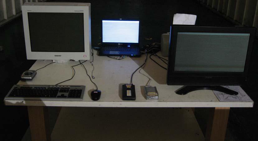
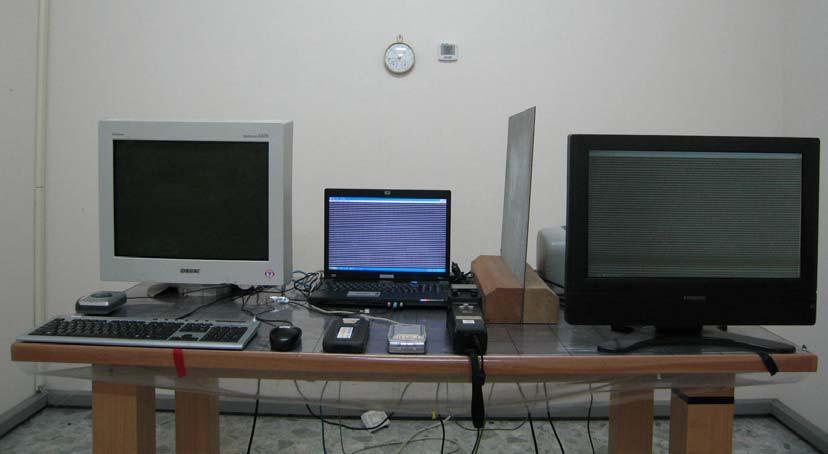
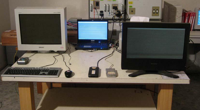
7 1.2. Tested System Details The types for all equipment, plus descriptions of all cables used in the tested system (including inserted cards) are: Product Manufacturer Model No. Serial No. Power Cord 1 Monitor SONY CPD-G Non-Shielded, 1.8m 2 Walkman AIWA HS-TA164 N/A N/A 3 Keyboard Logitech Y-SM N/A 4 USB Mouse Logitech M-UV83 HCB N/A 5 Microphone & Earphone PCHOME N/A N/A Non-Shielded, 2.0m 6 USB 2.0 HDD AACOM F12-UF N/A Power by PC 7 USB 2.0 HDD AACOM F12-UF N/A Power by PC 8 Printer EPSON StyLus C63 FAPY Non-Shielded, 1.9m 9 Monitor BenQ LT-20E17 N/A Non-Shielded, 1.8m 10 TS9980 R&S N/A N/A N/A 11 Notebook PC DELL PP18L Non-Shielded, 0.8m 12 Exchange Network Sun Moon Star PX Non-Shielded, 1.8m Signal Cable Type Signal cable Description A Audio Cable Non-Shielded, 1.6m B USB Cable Shielded, 1.5m C USB Cable Shielded, 1.5m D Microphone & Earphone Cable Non-Shielded, 1.6m E USB Cable Shielded, 1.5m F 1394 Cable Shielded, 1.2m G HDMI Cable Shielded, 1m H S-VIDEO Cable Shielded, 1.6m I COAXIAL Cable Shielded, 7.0m J LAN Cable Non-Shielded, 7.0m K USB Cable Shielded, 1.5m L D-SUB Cable Shielded, 1.8m, with two ferrite cores bonded M TELECOM Cable Non-Shielded, 7.0m N TELECOM Cable Non-Shielded, 7.0m Page: 7 of 50
8 1.3. Configuration of Test System 1.4. EUT Exercise Software (1) Setup the EUT and simulators as shown on 1.3. (2) Turn on the power of all equipment. (3) Boot the PC from Hard Disk. (4) PC reads test software from disk The Notebook PC's and far Notebook PC's monitor will show the transmitting and receiving (5) characteristics when the communication is success. (6) Wireless LAN function was used to perform the wireless data transmission. (7) Repeat the above procedure 5 to 6. Page: 8 of 50
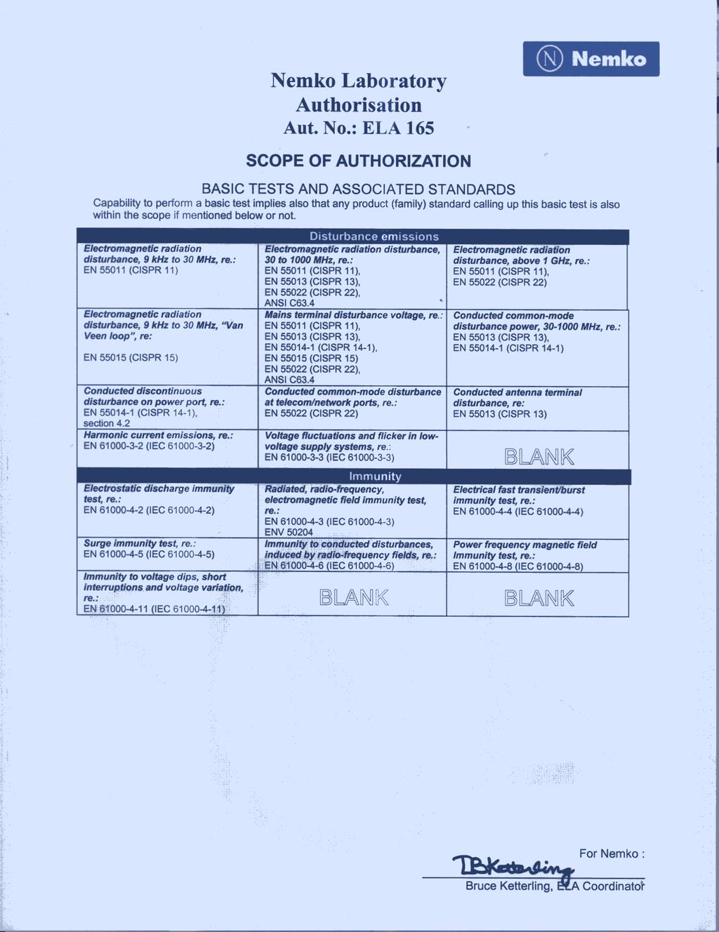
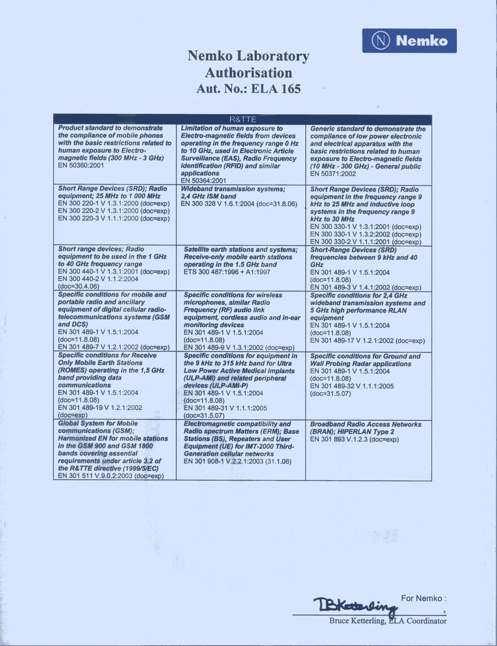
9 1.5. Test Facility Ambient conditions in the laboratory: Items Test Item Required (IEC 68-1) Actual Temperature ( C) Humidity (%RH) IEC Barometric pressure (mbar) Temperature ( C) Humidity (%RH) IEC Barometric pressure (mbar) Temperature ( C) IEC Barometric pressure (mbar) IEC Site Description: Accredited by NVLAP NVLAP Lab Code: Site Name: Site Address: Accredited by DNV Statement No. : LAB11 Accredited by Nemko Certificate No.: ELA 165 Accredited by TUV Rheinland Certificate No.: Accredited by CNLA Accredited Number: 0914 Quietek Corporation No. 5-22, Ruei-Shu Valley, Ruei-Ping Tsuen, Lin-Kou Shiang, Taipei, Taiwan, R.O.C. TEL : / FAX : service@quietek.com 0914 Page: 9 of 50
10 2. Conducted Emission 2.1. Test Equipmen The following test equipment are used during the conducted emission test: Item Equipment Manufacturer Model No. / Serial No. Last Cal. Remark 1 Test Receiver R & S ESCS 30 / /018 Sep., Artificial Mains Network R & S ENV4200 / /10 Feb., 2007 Peripherals 3 LISN R & S ESH3-Z5 / /002 Feb., 2007 EUT 4 Pulse Limiter R & S ESH3-Z2 / Feb., wire ISN R & S ENY41 / /001 Feb., Double 2-Wire ISN R & S ENY22 / /008 Feb., No.1 Shielded Room Note: All equipment upon which need to calibrated are with calibration period of 1 year Test Setup Shielded Room 0.8m Peripheral ( EUT ) 40cm 80cm AMN for Peripheral AMN for EUT 50 ohm Terminator Test Receiver Page: 10 of 50
11 2.3. Limits (1) Mains terminal Frequency MHz Limits (dbuv) Limit for conducted emissions of equipment intended to be used in Limit for conducted emissions telecommunication centers only QP AV QP AV Remarks: The limit decreases linearly with the logarithm of the frequency in the range 0.15 MHz ~ 0.50 MHz. (2) Telecommunication ports Limits (dbuv) Frequency MHz Limit for conducted emissions from telecommunication ports of equipment intended for use in telecommunication centers only Limit for conducted emissions from telecommunication ports QP AV QP AV Remarks: In the above table, the tighter limit applies at the band edges. Page: 11 of 50
12 2.4. Test Procedure AC Mains: The EUT and simulators are connected to the main power through a line impedance stabilization network (L.I.S.N.). This provides a 50 ohm /50uH coupling impedance for the measuring equipment. The peripheral devices are also connected to the main power through a LISN that provides a 50ohm /50uH coupling impedance with 50ohm termination. (Please refers to the block diagram of the test setup and photographs.) Both sides of AC line are checked for maximum conducted interference. In order to find the maximum emission, the relative positions of equipment and all of the interface cables must be changed according to ETSI EN : V1.6.1 ( ) on conducted measurement. The bandwidth of the field strength meter (R & S Test Receiver ESCS 30) is set at 9kHz. Telecommunication Port: The mains voltage shall be supplied to the EUT via the LISN when the measurement of telecommunication port is performed. The common mode disturbances at the telecommunication port shall be connected to the ISN, which is 150ohm impedance. Both alternative cables are tested related to the LCL requested. The measurement range is from 150kHz to 30MHz. The bandwidth of measurement is set to 9kHz. The 60dB LCL ISN is used for cat. 5 cable, 50dB LCL ISN is used for cat. 3 and 80dB LCL is wed for alternative one Test Specification According to ETSI EN : V1.6.1 ( ) EN 55022:1998+A1: A2: Uncertainty ± 2.26 db 2.7. Test Result The emission from the EUT was below the specified limits. The worst-case emissions are shown in section 12. The EUT complies the acceptance criterion and passes the test. Page: 12 of 50
13 3. Radiated Emission 3.1. Test Equipment The following test equipment are used during the Radiated emission test: Test Site Equipment Manufacturer Model No./Serial No. Last Cal. Site # 1 Test Receiver R & S ESVS 10 / /003 July, 2006 Spectrum Analyzer Advantest R3162/ May, 2007 Pre-Amplifier Advantest BB525C/ 3307A01812 May, 2007 Bilog Antenna SCHAFFNER CBL6112B / 2697 Nov., 2006 Site # 2 Test Receiver R & S ESCS 30 / / 022 Nov., 2006 Spectrum Analyzer Advantest R3162 / May, 2007 Pre-Amplifier Advantest BB525C/3307A01814 May, 2007 Bilog Antenna SCHAFFNER CBL6112B / 2705 Oct., 2006 Horn Antenna ETS 3115 / July, 2006 Pre-Amplifier QTK QTK-AMP-01/ 0001 July, 2006 Site # 3 Test Receiver R & S ESI 26 / / 004 May, 2007 Spectrum Analyzer Advantest R3162 / May, 2007 Pre-Amplifier QTK QTK-AMP-03 / 0003 May, 2007 Bilog Antenna SCHAFFNER CBL6112B / 2697 May, 2007 Horn Antenna ETS 3115 / July, 2006 Pre-Amplifier QTK QTK-AMP-01 / 0001 July, 2006 Note: 1. All equipments are calibrated every one year. 2. The test instruments marked by X are used to measure the final test results Test Setup 10m FRP Dome 1m to 4m Non-Conducted Table Load EUT Antenna Mast Dipole or Horn Antenna Antenna height can be moved from 1m to 4m, Antenna and turntable distance 3m 80cm Test Receiver Fully Soldered Ground Plane TO Controller To Receiver Page: 13 of 50
14 3.3. Limits Limits (dbuv/m) Frequency MHz Limit for radiated emissions from ancillary equipment intended for use in telecommunication centers only, and measured on a stand alone basis QP Limit for radiated emissions from ancillary equipment, measured on a stand alone basis QP Test Procedure The EUT and its simulators are placed on a turn table which is 0.8 meter above ground. The turn table can rotate 360 degrees to determine the position of the maximum emission level. The EUT was positioned such that the distance from antenna to the EUT was 10 meters.the antenna can move up and down between 1 meter and 4 meters to find out the maximum emission level. Both horizontal and vertical polarization of the antenna are set on measurement. In order to find the maximum emission, all of the interface cables must be manipulated according to ETSI EN : V1.6.1 ( ) on radiated measurement. The additional motch filter below 1GHz was used to measure the level of harmonics radiated emission during field dtrength of harmonics measurement. The bandwidth below 1GHz setting on the field strength meter (R&S Test Receiver ESCS 30 )is 120 khz, and 1MHz bandwidth is adpted above 1GHz. The frequency range from 30MHz to 10 th harmonics is checked Test Specification According to ETSI EN : V1.6.1 ( ) EN 55022:1998+A1: 2002+A2: Uncertainty ± 3.8 db 3.7. Test Result The emission from the EUT was below the specified limits. The worst-case emissions are shown in section 12. The EUT complies the acceptance criterion and passes the test. Page: 14 of 50
15 4. Power Harmonics, Voltage Fluctuation and Flicker 4.1. Test Equipment Item Instrument 4Manufacturer Type No/Serial No. Last Calibration 1 Power Harmonics Tester SCHAFFNER Profline S/N: HK54148 June, Analyzer SCHAFFNER CCN /X71887 June, No.3 Shielded Room Note: All equipments are calibrated every one year Test Setup Controller PC Power Analyzer Impedance Network Power Source EUT Load Non-Conducted 4.3. Limits Limits of Class A Harmonics Currents Harmonics Order n Maximum Permissible harmonic current A Odd harmonics Harmonics Order n Maximum Permissible harmonic current A Even harmonics n * 8/n n * 15/n Limits of Class B Harmonics Currents For Class B equipment, the harmonic of the input current shall not exceed the maximum permissible values given in table that is the limit of Class A multiplied by a factor of 1.5. Page: 15 of 50
16 Limits of Class C Harmonics Currents Report No. 074L146-RFCEP02V01 Harmonics Order Maximum Permissible harmonic current Expressed as a percentage of the input current at the fundamental frequency n % λ * n 39 3 (odd harmonics only) *λ is the circuit power factor Limits of Class D Harmonics Currents Harmonics Order Maximum Permissible harmonic current per watt ma/w Maximum Permissible harmonic current A n n 39 (odd harmonics only) 4.4. Test Procedure 3.85/n See limit of Class A The EUT is supplied in series with power analyzer from a power source having the same normal voltage and frequency as the rated supply voltage and the equipment under test. And the rated voltage at the supply voltage of EUT of 0.94 times and 1.06 times shall be performed Test Specification According to EN :2000+A1: 2001, EN :1995+A1: Uncertainty ± 3.23 % 4.7. Test Result The measurement of the power harmonics, which test at the extremes of EUT s supply range, was investigated and test result was shown in section 12. The EUT complies the acceptance criterion and passes the test. Test Result: (See Test Result) PASS FAIL Note: According to clause 7 of EN : 2000, equipment with a rated power of 75W or less, no limits apply. The test result is only for reference. Page: 16 of 50
17 5. Electrostatic Discharge (ESD) 5.1. Test Equipment Item Instrument Manufacturer Type No/Serial No. Last Calibration 1 ESD Simulator System SCHAFFNER NSG-438 S/N: 167 June, Horizontal Coupling Plane (HCP) 3 Vertical Coupling Plane (VCP) 4 No.3 Shielded Room QuieTek HCP AL50 N/A QuieTek VCP AL50 N/A Note: All equipments are calibrated every one year Test Setup Vertical Coupling Plane Insulation EUT Loads: Active Horizontal Coupling Plane 80cm Non-Conducted table ESD Simulator 470K ohm Resistor Metal Ground Plane 470K ohm Resistor 5.3. Test Level Item Environmental Phenomena Units Test Specification Performance Criteria Enclosure Port Electrostatic Discharge kv(charge Voltage) ±8 Air Discharge ±4 Contact Discharge B Page: 17 of 50
18 5.4. Test Procedure Direct application of discharges to the EUT: Contact discharge was applied only to conductive surfaces of the EUT. Air discharges were applied only to non-conductive surfaces of the EUT. During the test, it was performed with single discharges. For the single discharge time between successive single discharges will be keep longer 1 second. It was at least ten single discharges with positive and negative at the same selected point. The selected point, which was performed with electrostatic discharge, was marked on the red label of the EUT. Indirect application of discharges to the EUT: Vertical Coupling Plane (VCP): The coupling plane, of dimensions 0.5m x 0.5m, is placed parallel to, and positioned at a distance 0.1m from, the EUT, with the Discharge Electrode touching the coupling plane. The four faces of the EUT will be performed with electrostatic discharge. It was at least ten single discharges with positive and negative at the same selected point. Horizontal Coupling Plane (HCP): The coupling plane is placed under to the EUT. The generator shall be positioned vertically at a distance of 0.1m from the EUT, with the Discharge Electrode touching the coupling plane. The four faces of the EUT will be performed with electrostatic discharge. It was at least ten single discharges with positive and negative at the same selected point Test Specification According to EN :1995+A1: 1998+A2: Uncertainty ± % 5.7. Test Result The measurement of the electrostatic discharge was investigated and test result was shown in section 12. The EUT complies the acceptance criterion and passes the test. Page: 18 of 50
19 6. Radiated Susceptibility (RS) 6.1. Test Equipment Item Equipment Manufacturer Model No. / Serial No. Last Cal. 1 Signal Generator R & S SMY02 / /029 Oct., Power Amplifier A & R 100W10000M7 / A N/A 3 RF Power Amplifier OPHIRRF 5022F / 1075 N/A 4 Bilog Antenna Chase CBL6112B / 2452 Sep., Power Meter R & S NRVD / Jan., Directional Coupler A & R DC6180 / Jan., No.5 EMC Fully Chamber Note: All equipments are calibrated every one year Test Setup Antenna Mast 3 m Sensor Full-Anechoic Chamber Camera system EUT Load 1m 80cm Power Amplifier Field Meter Power Meter Signal Generator Computer controller Camera Monitor 6.3. Test Level Item Environmental Phenomena Units Test Specification Performance Criteria Enclosure Port Radio-Frequency MHz Electromagnetic Field V/m(Un-modulated, rms) 3 A Amplitude Modulated % AM (1kHz) 80 Page: 19 of 50
20 6.4. Test Procedure The EUT and load, which are placed on a table that is 0.8 meter above ground, are placed with one coincident with the calibration plane such that the distance from antenna to the EUT was 3 meters. Both horizontal and vertical polarization of the antenna and four sides of the EUT are set on measurement. In order to judge the EUT performance, a CCD camera is used to monitor EUT screen. All the scanning conditions are as follows: Condition of Test Remarks 1. Field Strength 3 V/m Level 2 2. Radiated Signal AM 80% Modulated with 1kHz sinusoidal audio signal 3. Scanning Frequency 80MHz MHz, 1400MHz MHz 4 Dwell Time 3 Seconds 5. Frequency step size f : 1% 6. The rate of Swept of Frequency 1.5 x 10⁻³ decades/s 6.5. Test Specification According to EN :1996+A1: 1998+A2: Uncertainty ± 6.17 % 6.7. Test Result The measurement of the radiated susceptibility was investigated and test result was shown in section 12. The EUT complies the acceptance criterion and passes the test. Page: 20 of 50

21 7. Electrical Fast Transient/Burst (EFT/B) 7.1. Test Equipment Item Instrument Manufacturer Type No/Serial No. Last Calibration Fast Transient/Burst 1 Generator 2 No.2 Shielded Room SCHAFFNER NSG 2050 S/N: AR June, 2006 Note: All equipments are calibrated every one year Test Setup Page: 21 of 50
22 7.3. Test Level Item Environmental Phenomena Units Test Specification Performance Criteria Ports for signal lines and control lines kv (Peak) +0.5 Fast Transients Common Mode Tr/Th ns 5/50 B Rep. Frequency khz 5 Input DC Power Ports kv (Peak) +0.5 Fast Transients Common Mode Tr/Th ns 5/50 B Rep. Frequency khz 5 Input AC Power Ports kv (Peak) +1 Fast Transients Common Mode Tr/Th ns 5/50 B Rep. Frequency khz Test Procedure The EUT and load are placed on a table that is 0.8 meter above a metal ground plane measured 1m*1m min. and 0.65mm thick min. And projected beyond the EUT by at least 0.1m on all sides. For Signal Ports and Telecommunication Ports: The EFT interference signal is through a coupling clamp device couples to the signal and control lines of the EUT with burst noise for 1min. For Input DC and AC Power Ports: The EUT is connected to the power mains through a coupling device that directly couples the EFT interference signal. Each of the Line and Neutral conductors is impressed with burst noise for 1 min. The length of power cord between the coupling device and the EUT shall be 1m Test Specification According to EN :1995+A1: 2001+A2: Uncertainty ± 8.80 % 7.7. Test Result The measurement of the Electrical Fast Transient/Burst was investigated and test result was shown in section 12. The EUT complies the acceptance criterion and passes the test. Page: 22 of 50
23 8. Surge 8.1. Test Equipment Item Instrument Manufacturer Type No/Serial No. Last Calibration 1 Surge Generator SCHAFFNER NSG 2050 S/N: AR 2 No.6 Shielded Room June, 2006 Note: All equipment upon which need to calibrated are with calibration period of 1 year Test Setup PC Surge Generator EUT Load Non-Conducted Table Non-Conducted Table 8.3. Test Level Item Environmental Phenomena Units Test Specification Performance Criteria Telecommunication Ports (See 1) and 2)) Surges Tr/Th us Line to Ground kv Telecommunication Ports in Telecom Centres (See 1) and 2)) Surges Tr/Th us Line to Ground kv AC Input and AC Output Power Ports Surges Line to Line Line to Ground Tr/Th us kv kv AC Input and AC Output Power Ports in Telecom Centres Surges Tr/Th us Line to Line kv Line to Ground kv 1.2/50 (8/20) ± 1 1.2/50 (8/20) ± /50 (8/20) ±1 ± 2 1.2/50 (8/20) ±0.5 ± 1 B B B B Notes: 1) Applicable only to ports which according to the manufacturer s may directly to outdoor cables. 2) Where normal functioning cannot be achieved because of the impact of the CDN on the EUT, no immunity test shall be required. Page: 23 of 50
24 8.4. Test Procedure The EUT and its load are placed on a table that is 0.8 meter above a metal ground plane measured 1m*1m min. and 0.65mm thick min. And projected beyond the EUT by at least 0.1m on all sides. The length of power cord between the coupling device and the EUT shall be 2m or less. For Signal Ports and Telecommunication Ports The disturbance signal is through a coupling and decoupling networks (CDN) device couples to the signal and Telecommunication lines of the EUT. For Input and Output AC Power or DC Input and DC Output Power Ports: The EUT is connected to the power mains through a coupling device that directly couples the Surge interference signal. The surge noise shall be applied synchronized to the voltage phase at 0 0, 90 0, 180 0, and the peak value of the a.c. voltage wave. (Positive and negative) Each of Line-Earth and Line-Line is impressed with a sequence of five surge voltages with interval of 1 min Test Specification According to EN :1995+A Uncertainty ± 7.93 % 8.7. Test Result The measurement of the Surge was investigated and test result was shown in section 12. The EUT complies the acceptance criterion and passes the test. Page: 24 of 50
25 9. Conducted Susceptibility (CS) 9.1. Test Equipment Item Equipment Manufacturer Model No. / Serial No. Last Cal. 1 CS SYSTEM SCHAFFNER NSG 2070 March, CDN SCHAFFNER CDN M016S / Dec., CDN SCHAFFNER CDN M016S / Dec., FIXED PAD SCHAFFNER INA / 2115 N/A 5 EM Clamp KEMZ 801 / March, No.6 Shielded Room Note: All equipments are calibrated every one year Test Setup Aux equipment CDN EUT CDN Aux equipment Ground Reference Plane T Non-Conducted Table T2 RF-Generator PA 9.3. Test Level Item Environmental Phenomena Units Test Specification Performance Criteria AC Input and AC Output & DC Input and DC output Power Ports & Functional Earth Ports Radio-Frequency Common Mode. Amplitude Modulated MHz V (rms, Unmodulated) % AM (1kHz) Source Impedance Ω A Page: 25 of 50
26 9.4. Test Procedure The EUT are placed on a table that is 0.8 meter height, and a Ground reference plane on the table, EUT are placed upon table and use a 10cm insulation between the EUT and Ground reference plane. For Signal Ports and Telecommunication Ports The disturbance signal is through a coupling and decoupling networks (CDN) or EM-clamp device couples to the signal and Telecommunication lines of the EUT. For Input DC and AC Power Ports The EUT is connected to the power mains through a coupling and decoupling networks for power supply lines. And directly couples the disturbances signal into EUT. Used CDN-M2 for two wires or CDN-M3 for three wires. All the scanning conditions are as follows: Condition of Test Remarks 1. Field Strength 130dBuV(3V) Level 2 2. Radiated Signal AM 80% Modulated with 1kHz sinusoidal audio signal 3. Scanning Frequency 0.15MHz 80MHz 4 Dwell Time 3 Seconds 5. Frequency step size f : 1% 6. The rate of Swept of Frequency 1.5 x 10⁻³ decades/s 9.5. Test Specification According to EN :1996 +A1: Uncertainty ± 6.17 % 9.7. Test Result The measurement of the Conducted Susceptibility was investigated and test result was shown in section 12. The EUT complies the acceptance criterion and passes the test. Page: 26 of 50
27 10. Voltage Dips and Interruption Test Equipment Item Instrument Manufacturer Type No/Serial No. Last Calibration 1 Voltage Dips Generator SCHAFFNER NSG 2050 S/N: AR 2 No.6 Shielded Room June, 2006 Note: All equipments are calibrated every one year Test Setup To AC Line Voltage Dips/ Interruptions /Variations Simulator AC Power Line to EUT EUT Load Non-Conducted Table 80cm Controller Computer Printer Test Level Item Environmental Phenomena Units Test Specification Performance Criteria AC Input and AC Output Power Ports Voltage Dips % Reduction ms B Voltage Dips % Reduction ms C Voltage Interruptions % Reduction ms > 95 % 5000 C Page: 27 of 50
28 10.4. Test Procedure The EUT and its load are placed on a table which is 0.8 meter above a metal ground plane measured 1m*1m min. and 0.65mm thick min. And projected beyond the EUT by at least 0.1m on all sides. The power cord shall be used the shortest power cord as specified by the manufacturer. For Voltage Dips/ Interruptions test: The selection of test voltage is based on the rated power range. If the operation range is large than 20% of lower power range, both end of specified voltage shall be tested. Otherwise, the typical voltage specification is selected as test voltage. The EUT is connected to the power mains through a coupling device that directly couples to the Voltage Dips and Interruption Generator. The EUT shall be tested for 30% voltage dip of supplied voltage and duration 10ms, with a sequence of three voltage dips with intervals of 10 seconds, for 60% voltage dip of supplied voltage and duration 100ms with a sequence of three voltage dips with intervals of 10 seconds, and for 95% voltage interruption of supplied voltage and duration 5000ms with a sequence of three voltage interruptions with intervals of 10 seconds. Voltage phase shifting are shall occur at 0 0, 45 0, 90 0,135 0,180 0,225 0, 270 0,315 0 of the voltage Test Specification According to EN :1994+A1: Uncertainty ± 2.03 % Test Result The measurement of the Voltage Dips and Interruption was investigated and test result was shown in section 12. The EUT complies the acceptance criterion and passes the test. Page: 28 of 50
29 11. EMC Reduction Method During Compliance Testing No modification was made during testing. Page: 29 of 50
30 12. Test Result The test results in the emission and the immunity were performed according to the requirements of measurement standard and process. Quietek Corporation is assumed full responsibility for the accuracy and completeness of these measurements. The test data of the emission is listed as below. All the tests were carried out with the EUT in normal operation, which was defined as: EMI Mode EMS Mode Mode1: Normal Operation (AR5BXB63+MS-6837D) Mode1: Normal Operation (AR5BXB63+MS-6837D) Page: 30 of 50
31 12.1. Test Data of Conducted Emission Product : Notebook Test Item : Conducted Emission Test Site : No.1 Shielded Room Power Line : Line 1 Test Mode : Mode1: Normal Operation (AR5BXB63+MS-6837D) Frequency Correct Reading Measurement Margin Limit Factor Level Level MHz db dbuv dbuv db dbuv LINE 1 Quasi-Peak Average Note: 1. All Reading Levels are Quasi-Peak and Average value. 2. " " means the worst emission level. 3. Measurement Level = Reading Level + Correct Factor Page: 31 of 50
32 Product : Notebook Test Item : Conducted Emission Test Site : No.1 Shielded Room Power Line : Line 2 Test Mode : Mode1: Normal Operation (AR5BXB63+MS-6837D) Frequency Correct Reading Measurement Margin Limit Factor Level Level MHz db dbuv dbuv db dbuv LINE 2 Quasi-Peak Average Note: 1. All Reading Levels are Quasi-Peak and Average value. 2. " " means the worst emission level. 3. Measurement Level = Reading Level + Correct Factor Page: 32 of 50
33 Product : Notebook Test Item : Impedance Stabilization Network Test Site : No.1 Shielded Room Test Mode : Mode1: Normal Operation (AR5BXB63+MS-6837D)(LAN Cable-100 Mbps) Frequency Correct Reading Measurement Margin Limit Factor Level Level MHz db dbuv dbuv db dbuv Quasi-Peak Average Note: 1. All Reading Levels are Quasi-Peak and Average value. 2. " " means the worst emission level. 3. Measurement Level = Reading Level + Correct Factor Page: 33 of 50
34 Product : Notebook Test Item : Impedance Stabilization Network Test Site : No.1 Shielded Room Test Mode : Mode1: Normal Operation (AR5BXB63+MS-6837D)(LAN Cable-10 Mbps) Frequency Correct Reading Measurement Margin Limit Factor Level Level MHz db dbuv dbuv db dbuv Quasi-Peak Average Note: 1. All Reading Levels are Quasi-Peak and Average value. 2. " " means the worst emission level. 3. Measurement Level = Reading Level + Correct Factor Page: 34 of 50
35 Product : Notebook Test Item : Impedance Stabilization Network Test Site : No.1 Shielded Room Test Mode : Mode1: Normal Operation (AR5BXB63+MS-6837D) (Telecom) Frequency Correct Reading Measurement Margin Limit Factor Level Level MHz db dbuv dbuv db dbuv Quasi-Peak Average Note: 1. All Reading Levels are Quasi-Peak and Average value. 2. " " means the worst emission level. 3. Measurement Level = Reading Level + Correct Factor Page: 35 of 50
36 Product : Notebook Test Item : Impedance Stabilization Network Test Site : No.1 Shielded Room Test Mode : Mode1: Normal Operation (AR5BXB63+MS-6837D) (GIGA CUR) Frequency Correct Reading Measurement Margin Limit Factor Level Level MHz db dbuv dbuv db dbuv Quasi-Peak Average Note: 1. All Reading Levels are Quasi-Peak and Average value. 2. " " means the worst emission level. 3. Measurement Level = Reading Level + Correct Factor Page: 36 of 50
37 Product : Notebook Test Item : Impedance Stabilization Network Test Site : No.1 Shielded Room Test Mode : Mode1: Normal Operation (AR5BXB63+MS-6837D) (GIGA VOL) Frequency Correct Reading Measurement Margin Limit Factor Level Level MHz db dbuv dbuv db dbuv Quasi-Peak Average Note: 1. All Reading Levels are Quasi-Peak and Average value. 2. " " means the worst emission level. 3. Measurement Level = Reading Level + Correct Factor Page: 37 of 50
38 12.2. Test Data of Radiated Emission Product : Notebook Test Item : General Radiated Emission Test Site : No.3 OATS Test Mode : Mode1: Normal Operation (AR5BXB63+MS-6837D) Frequency Correct Reading Measurement Margin Limit Factor Level Level MHz db dbuv dbuv/m db dbuv/m Horizontal Vertical Note: 1. All Readings below 1GHz are Quasi-Peak, above are performed with peak and/or average measurements as necessary. 2. means the worst emission level. 3. Measurement Level = Reading Level + Correct Factor Page: 38 of 50
39 12.3. Test Data of Power Harmonics, Voltage Flucturation and Flicker Product : Notebook Test Item : Power Harmonics Classification : Class D Test Mode : Mode1: Normal Operation (AR5BXB63+MS-6837D) Test Result: Pass Current & voltage waveforms Source qualification: Normal Current (Amps) Voltage (Volts) Harmonics and Class D limit line European Limits Current RMS(Amps) Harmonic # Test result: Pass Worst harmonic was #7 with 13.63% of the limit. Page: 39 of 50
40 Test Result: Pass Source qualification: Normal THC(A): 0.06 I-THD(%): POHC(A): POHC Limit(A): Highest parameter values during test: V_RMS (Volts): Frequency(Hz): I_Peak (Amps): I_RMS (Amps): I_Fund (Amps): Crest Factor: Power (Watts): 86.9 Power Factor: Harm# Harms(avg) 100%Limit %of Limit Harms(max) 150%Limit %of Limit Status Pass Pass Pass Pass Pass Pass Pass Pass Pass Pass Pass Pass Pass Pass Pass Pass Pass Pass Pass Dynamic limits were applied for this test. The highest harmonics values in the above table may not occur at the same window as the maximum harmonics/limit ratio. 2:According to EN paragraph 7 the note 1 and 2 are valid for all applications having an active input power >75W. Others the result should be pass. Page: 40 of 50
41 Product : Notebook Test Item : Voltage Fluctuations and Flicker Test Mode : Mode1: Normal Operation (AR5BXB63+MS-6837D) Test Result: Pass Pst i and limit line Status: Test Completed European Limits Pst :25:55 Plt and limit line Plt :25:55 Parameter values recorded during the test: Vrms at the end of test (Volt): Highest dt (%): 0.00 Test limit (%): 3.30 Pass Time(mS) > dt: 0.0 Test limit (ms): Pass Highest dc (%): 0.00 Test limit (%): 3.30 Pass Highest dmax (%): 0.00 Test limit (%): 4.00 Pass Highest Pst (10 min. period): Test limit: Pass Highest Plt (2 hr. period): Test limit: Pass Page: 41 of 50
42 12.4. Test Data of Electrostatic Discharge Product : Notebook Test Item : Electrostatic Discharge Test Site : No.3 Shielded Room Test Mode : Mode1: Normal Operation (AR5BXB63+MS-6837D) Item Amount of Discharge Voltage Required Criteria Complied To Criteria (A, B, C) Results Air Discharge kV -8kV B B B B Pass Pass Contact Discharge kV -4kV B B B B Pass Pass Indirect Discharge 50 +4kV B B Pass (HCP) 50-4kV B B Pass Indirect Discharge 50 +4kV B B Pass (VCP Front) 50-4kV B B Pass Indirect Discharge 50 +4kV B B Pass (VCP Left) 50-4kV B B Pass Indirect Discharge 50 +4kV B B Pass (VCP Back) 50-4kV B B Pass Indirect Discharge 50 +4kV B B Pass (VCP Right) 50-4kV B B Pass Note: The testing performed is from lowest level up to the highest level as required by standard, but only highest level is shown on the report. NR: No Requirement Meet criteria A: Operate as intended during and after the test Meet criteria B: Operate as intended after the test Meet criteria C: Loss/Error of function Additional Information EUT stopped operation and could / could not be reset by operator at kv. No false alarms or other malfunctions were observed during or after the test. Page: 42 of 50
43 12.5. Test Data of Radiated Susceptibility Product : Notebook Test Item : Radiated Susceptibility Test Site : No.5 EMC fully Chamber Test Mode : Mode1: Normal Operation (AR5BXB63+MS-6837D) Frequency (MHz) Position (Angle) Polarity (H or V) Field Strength (V/m) Required Criteria Complied To Criteria (A, B, C) Results Front H 3 A A Pass Front V 3 A A Pass Back H 3 A A Pass Back V 3 A A Pass Left H 3 A A Pass Left V 3 A A Pass Right H 3 A A Pass Right V 3 A A Pass Top H 3 A A Pass Top V 3 A A Pass Down H 3 A A Pass Down V 3 A A Pass Front H 3 A A Pass Front V 3 A A Pass Back H 3 A A Pass Back V 3 A A Pass Left H 3 A A Pass Left V 3 A A Pass Right H 3 A A Pass Right V 3 A A Pass Top H 3 A A Pass Top V 3 A A Pass Down H 3 A A Pass Down V 3 A A Pass Note: The testing performed is from lowest level up to the highest level as required by standard, but only highest level is shown on the report. Meet criteria A: Operate as intended during and after the test Meet criteria B: Operate as intended after the test Meet criteria C: Loss/Error of function Additional Information There was no observable degradation in performance. EUT stopped operation and could / could not be reset by operator at at frequency MHz. No false alarms or other malfunctions were observed during or after the test. V/m Page: 43 of 50
44 12.6. Test Data of Electrical Fast Transient Product : Notebook Test Item : Electrical Fast Transient Test Site : No.2 Shielded Room Test Mode : Mode1: Normal Operation (AR5BXB63+MS-6837D) Inject Line Polarity Voltage (kv) Inject Time (Second) Inject Method Required Criteria Complied to Criteria Result L + N +PE ± 1 60 Direct B A Pass LAN ± Clamp B A Pass Telecom ± Clamp B B Pass Note: The testing performed is from lowest level up to the highest level as required by standard, but only highest level is shown on the report. Meet criteria A : Operate as intended during and after the test Meet criteria B : Operate as intended after the test Meet criteria C : Loss/Error of function Additional Information EUT stopped operation and could / could not be reset by operator at Line. No false alarms or other malfunctions were observed during or after the test. kv of Page: 44 of 50
45 12.7. Test Data of Surge Product : Notebook Test Item : Surge Test Site : No. 6 Shielded Room Test Mode : Mode1: Normal Operation (AR5BXB63+MS-6837D) Inject Line Polarity Angle Voltage (kv) Time Interval (Second) Inject Method Required Criteria Complied to Criteria Result L-N ± Direct B A Pass L-N ± Direct B A Pass L-N ± Direct B A Pass L-N ± Direct B A Pass N-PE ± Direct B A Pass N-PE ± Direct B A Pass N-PE ± Direct B A Pass N-PE ± Direct B A Pass L+PE ± Direct B A Pass L+PE ± Direct B A Pass L+PE ± Direct B A Pass L+PE ± Direct B A Pass Note: The testing performed is from lowest level up to the highest level as required by standard, but only highest level is shown on the report. Meet criteria A : Operate as intended during and after the test Meet criteria B : Operate as intended after the test Meet criteria C : Loss/Error of function Additional Information EUT stopped operation and could / could not be reset by operator at Line. No false alarms or other malfunctions were observed during or after the test. kv of Page: 45 of 50
46 12.8. Test Data of Conducted Susceptibility Product : Notebook Test Item : Conducted Susceptibility Test Site : No. 6 Shielded Room Test Mode : Mode1: Normal Operation (AR5BXB63+MS-6837D) Frequency Voltage Inject Tested Port of Required Performance Result Range Applied Method EUT Criteria Criteria (MHz) dbuv(v) Complied To 0.15~80 130(3V) CDN AC IN A A PASS 0.15~80 130(3V) Clamp LAN A A PASS 0.15~80 130(3V) Clamp LAN GIGA A A PASS 0.15~80 130(3V) Clamp Telecom A A PASS Note: The testing performed is from lowest level up to the highest level as required by standard, but only highest level is shown on the report. Meet criteria A: Operate as intended during and after the test Meet criteria B: Operate as intended after the test Meet criteria C: Loss/Error of function Additional Information EUT stopped operation and could / could not be reset by operator at kv of Line. No false alarms or other malfunctions were observed during or after the test. The acceptance criteria were met, and the EUT passed the test. Page: 46 of 50
47 12.9. Test Data of Voltage Dips and Interruption Product : Notebook Test Item : Voltage Dips and Interruption Test Site : No.6 Shielded Room Test Mode : Mode1: Normal Operation (AR5BXB63+MS-6837D) Voltage Dips and Interruption Reduction (%) Angle Test Duration (ms) Required Performance Criteria Performance Criteria Complied To Test Result B A PASS B A PASS B A PASS B A PASS B A PASS B A PASS B A PASS B A PASS C A PASS C A PASS C A PASS C A PASS C A PASS C A PASS C A PASS C A PASS > C A PASS > C A PASS > C A PASS > C A PASS > C A PASS > C A PASS > C A PASS > C A PASS Meet criteria A: Operate as intended during and after the test Meet criteria B: Operate as intended after the test Meet criteria C: Loss/Error of function Additional Information The nominal voltage of EUT is 230V. EUT stopped operation and could / could not be reset by operator at kv of Line. No false alarms or other malfunctions were observed during or after the test. The acceptance criteria were met, and the EUT passed the test. Page: 47 of 50
48 Attachment 1: EUT Test Photographs Page: 48 of 50

49 Report No.: 074L146-RFCEP02V01 Attachment 1: EUT Test Setup Photographs Front View of Conducted Test Back View of Conducted Test Page : 1 of 10


50 Report No.: 074L146-RFCEP02V01 Front View of Conducted Test (ISN) Back View of Conducted Test (ISN) Page : 2 of 10

 Back CUR) Page : 3 of 10")
51 Report No.: 074L146-RFCEP02V01 Front View of Conducted Test (GIGA CUR) Back View of Conducted Test (GIGA CUR) Page : 3 of 10


 Page : 4 of 10")
52 Report No.: 074L146-RFCEP02V01 Front View of Conducted Test (GIGA VOL) Back View of Conducted Test (GIGA VOL) Page : 4 of 10


53 Report No.: 074L146-RFCEP02V01 Front View of Radiated Test Back View of Radiated Test-Clamp Page : 5 of 10


54 Report No.: 074L146-RFCEP02V01 Power Harmonics Test Setup ESD Test Setup Page : 6 of 10


55 Report No.: 074L146-RFCEP02V01 Radiated Susceptibility Test Setup EFT/B Test Setup Page : 7 of 10

56 Report No.: 074L146-RFCEP02V01 EFT/B Test Setup Clamp SURGE Test Setup Page : 8 of 10


57 Report No.: 074L146-RFCEP02V01 Conducted Susceptibility Test Setup Conducted Susceptibility Test Setup- Clamp Page : 9 of 10

58 Report No.: 074L146-RFCEP02V01 Voltage Dips Test Setup Page : 10 of 10
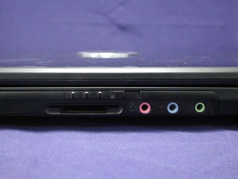
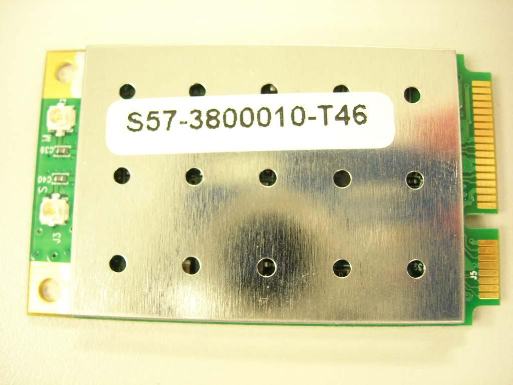
59 Attachment 2: EUT Detailed Photographs Page: 49 of 50

 EUT Photo")
60 Report No.: 074L146-RFCEP02V01 Attachment 2 : EUT Detailed Photographs (1) EUT Photo (2) EUT Photo Page : 1 of 7

61 Report No.: 074L146-RFCEP02V01 (3) EUT Photo (4) EUT Photo Page : 2 of 7

62 Report No.: 074L146-RFCEP02V01 (5) EUT Photo (6) EUT Photo Page : 3 of 7


63 Report No.: 074L146-RFCEP02V01 (7) EUT Photo (8) EUT Photo Page : 4 of 7

 EUT Photo (10)")
64 Report No.: 074L146-RFCEP02V01 (9) EUT Photo (10) EUT Photo Page : 5 of 7

 EUT Photo")
65 Report No.: 074L146-RFCEP02V01 (11) EUT Photo (12) EUT Photo Page : 6 of 7

 EUT Photo")
66 Report No.: 074L146-RFCEP02V01 (13) EUT Photo (14) EUT Photo Page : 7 of 7
67 Reference: Laboratory of License Page: 50 of 50
68
69
70

71
72

73
74
Report No R-RFCEP02V01. Test Report MSI / MS-6837D. Date of Receipt Aug. 21, Issued Date Sep. 11, 2007
 Test Report Product Name Model No. Transmitter Module Notebook MS-163D, EX610 Atheros / AR5BXB63 MSI / MS-6837D Applicant Address MICRO-STAR INTL Co., LTD. No. 69, Li-De St., Jung-He City, Taipei Hsien,
Report No. 074L076-RFCEP02V01-A. Test Report MSI / MS-6837D
 Test Report Product Name Model No. Transmitter Module Notebook MS-16371,MS-16372 Atheros / AR5BXB63 MSI / MS-6837D Applicant MICRO-STAR INT L Co., LTD. Address No. 69, Li-De St., Jung-He City, Taipei Hsien,
Report No R-RFCEP02V01. Test Report. MICRO-STAR INT L Co., LTD. No. 69, Li-De St., Jung-He City, Taipei Hsien, Taiwan, R.O.C.
 Test Report Product Name Model No. Notebook MS-1242, U200 Transmitter Module. Ralink / RT3090 (MS-6891) Bluetooth Module MSI / MS-6837D Applicant Address MICRO-STAR INT L Co., LTD. No. 69, Li-De St., Jung-He
Test Report. Product Name: Access Point Model No.: MS-6809 FCC ID: DoC
 Test Report Product Name: Access Point Model No.: MS-6809 FCC ID: DoC Applicant : MICRO-STAR INT L Co., LTD Address : No 69, Li-De st., Jung-He City, Taipei Hsien, Taiwan, R.O.C Date of Receipt : June
Report No. 103S085E-RFCEP02V01-A. Test Report
 Test Report Product Name Notebook Model No. MS-1244 Transmitter Module. Ralink / RT3090 (MS-6891) luetooth Module MSI / MS-6837D Applicant Address MICRO-STAR INT L Co., LTD. No. 69, Li-De St., Jung-He
Test Report. Product Name : PC2PC-Bluetooth Model No. : MS-6967 FCC ID. : I4L-MS6967
 Test Report Product Name : PC2PC-Bluetooth Model No. : MS-6967 FCC ID. : I4L-MS6967 Applicant : MICRO-STAR INT'L Co., LTD. Address : No. 69, Li-De St, Jung-He City, Taipei Hsieh, Taiwan, R.O.C. Date of
Page: 1 of 19 EMC TEST REPORT EN55024:1998+A2:2003
 Page: 1 of 19 EMC TEST REPORT Reference No. Applicant : WT05110894 : Gembird Electronics Ltd. Equipment Under Test (EUT) : Product Name : Card reader Model No : USB2.0A LL-in-1 Standards : EN55022:1998+A2:2003
Sensoray. Model 819. Tests Conducted by: ElectroMagnetic Investigations, LLC. May 10, 2013
 European Union (EU) Council Directive 2004/108/EC Electromagnetic Compatibility (EMC) and FCC Part 15 Subpart B Class B Test Report for Information Technology Equipment Sensoray Model 819 May 10, 2013
Test Report. Model No.: NF592XX-YYYY-ZZ(X,Y & Z: Stands for A-Z & 0-9 ) HBJC1XXF592-YYYY-ZZ (X,Y & Z: Stands for A-Z & 0-9 )
 HBJC1XXF592-YYYY-ZZ (X,Y & Z: Stands for A-Z & 0-9 )") Test Report Applicant: Product Name: Brand Name: Jetway Information Co.,Ltd Motherboard/Barebone N/A Model No.: NF592XX-YYYY-ZZ(X,Y & Z: Stands for A-Z & 0-9 ) HBJC1XXF592-YYYY-ZZ (X,Y & Z: Stands for
Test Report Applicant: Product Name: Brand Name: Jetway Information Co.,Ltd Motherboard/Barebone N/A Model No.: NF592XX-YYYY-ZZ(X,Y & Z: Stands for A-Z & 0-9 ) HBJC1XXF592-YYYY-ZZ (X,Y & Z: Stands for
FCC Part 15B Test Report
 Shenzhen Toby Technology Co., Ltd. Report No.: TB-FCC111757 Page: 1 of 18 FCC Part 15B Test Report Application No. : TB11081419 Applicant : Ingtron Enterprise Co., Ltd. Equipment Under Test (EUT) EUT Name
FCC Test Report (Class II Permissive Change)
") FCC Test Report (Class II Permissive Change) Product Name Intel Wireless-AC 9560 Model No. 9560NGW FCC ID. 2AKHF9560NG Applicant TONGFANG HONGKONG (SUZHOU) LIMITED Address NO. 83 Wu Lane, Suzhou Industrial
FCC Test Report (Class II Permissive Change) Product Name Intel Wireless-AC 9560 Model No. 9560NGW FCC ID. 2AKHF9560NG Applicant TONGFANG HONGKONG (SUZHOU) LIMITED Address NO. 83 Wu Lane, Suzhou Industrial
FCC TEST REPORT for Aeon Labs LLC. Aeon Minimote Model No.: DS03202B-ZWUS, DS03202W-ZWUS
 Page 1 of 22 FCC TEST REPORT for Aeon Labs LLC. Aeon Minimote Model No.: DS03202B-ZWUS, DS03202W-ZWUS Prepared for Address Prepared By Address : Aeon Labs LLC. : 121 Buckingham drive, unit36 santa claras
FCC Part 15 Subpart B Test Report. FCC PART 15 Subpart B Class B: 2014
 Shenzhen CTL Electromagnetic Technology Co., Ltd. Tel: +86-755-89486194 Fax: +86-755-26636041 FCC Part 15 Subpart B Test Report FCC PART 15 Subpart B Class B: 2014 Report Reference No...: CTL1408272147-F
FCC TEST REPORT For. ETI Solid State Lighting (Zhuhai) Ltd. LED downlight Model No.: XX
 Ltd. LED downlight Model No.: XX") Page 1 of 24 FCC TEST REPORT For ETI Solid State Lighting (Zhuhai) Ltd LED downlight Model No.: 531931XX Prepared for Address Prepared by Address : ETI Solid State Lighting (Zhuhai) Ltd : No.1, Zhongzhu
Page 1 of 24 FCC TEST REPORT For ETI Solid State Lighting (Zhuhai) Ltd LED downlight Model No.: 531931XX Prepared for Address Prepared by Address : ETI Solid State Lighting (Zhuhai) Ltd : No.1, Zhongzhu
FCC TEST REPORT D-LINK CORPORATION
 FCC TEST REPORT REPORT NO.: RF921014R02 MODEL NO.: DWL-120(refer to page 6 for other models) RECEIVED: October 14, 2003 TESTED: October 16 ~ October 17, 2003 APPLICANT: ADDRESS: D-LINK CORPORATION NO.8,
CENTRE OF TESTING SERVICE INTERNATIONAL
 CENTRE OF TESTING SERVICE INTERNATIONAL OPERATE ACCORDING TO ISO/IEC 17025 IC TEST REPORT TEST REPORT NUMBER : CGZ3150202-00095-E A101,No.65,Zhuji Highway,Tianhe District,Guangzhou, Guangdong, China TEST
FCC Test Report (Class II Permissive Change)
") FCC Test Report (Class II Permissive Change) Product Name 802.11abgn/11ac WLAN + Bluetooth PCI-E Mini Card Model No BCM94360HMB FCC ID QDS-BRCM1082 Applicant Broadcom Corporation Address 190 Mathilda Place
FCC Test Report (Class II Permissive Change) Product Name 802.11abgn/11ac WLAN + Bluetooth PCI-E Mini Card Model No BCM94360HMB FCC ID QDS-BRCM1082 Applicant Broadcom Corporation Address 190 Mathilda Place
Report On. FCC Testing of the Pace Plc 16x4 Hybrid Gateway Cable Set Top Box COMMERCIAL-IN-CONFIDENCE
 Report On FCC Testing of the Pace Plc 16x4 Hybrid Gateway Cable Set Top Box Document 75926325 Report 01 Issue 1 April 2014 TÜV SÜD Product Service, Octagon House, Concorde Way, Segensworth North, Fareham,
EN : 2015 IEC :2014 TEST REPORT FOR LED ILLUMINATOR MODEL NUMBER: P1347 REPORT NUMBER: E1V1 ISSUE DATE: MAY 15, 2017
 EN 60601-1-2: 2015 IEC 60601-1-2:2014 TEST REPORT FOR LED ILLUMINATOR MODEL NUMBER: P1347 REPORT NUMBER: 11473017- E1V1 ISSUE DATE: MAY 15, 2017 Prepared for TECHNI-QUIP CORPORATION 530 BOULDER COURT SUITE
FCC PART MEASUREMENT AND TEST REPORT FOR. DongGuan City FLYSKY Remote Model Co., Ltd.
 FCC PART 15.249 MEASUREMENT AND TEST REPORT FOR DongGuan City FLYSKY Remote Model Co., Ltd. No.41 Road West, BanHu Village, HuangJiang Town, DongGuan City, GuangDong Porvince, China FCC ID: VPOFLYSKY002
APPLICATION OF CERTIFICATION For. TTE Technology Inc. LCD TV FCC ID: W8ULE32HDE3000
 FCC ID:W8ULE32HDE3000 APPLICATION OF CERTIFICATION For TTE Technology Inc. LCD TV Brand Name TCL Model Number LE32HDE3000; LE32HDE3011 LE32HDE5311; LE32HDF3310TA LE32HDF3311; LE32HDF3312 FCC ID: W8ULE32HDE3000
Testing. Maker Works. Applicant: Model No.: FCC ID: Jun., May to 16. Date of Test: PASS* Test Result: Signature: Authorized. this report.
 1 Cover Page Shenzhen Zhongjian Nanfang Testing Co., Ltd. FCC REPORT Applicant: Address of Applicant: Maker Works Technology INC Building C3, Floor 4th, Zhiyuan, Xili, Nanshan District, ShenZhen 518057
FCC ID: IMK-ILCISA EMI TEST REPORT
 15.247 Certification FCC ID: IMK-ILCISA EMI TEST REPORT On SYMPHONY ISA Card Prepared for Proxim 295 N. Bernardo Ave Mountain View, CA 94043 Tel: (650)960-1630 Fax: (650)960-0332 Prepared by Electronic
CENTRE OF TESTING SERVICE INTERNATIONAL OPERATE ACCORDING TO ISO/IEC FCC ID TEST REPORT
 CENTRE OF TESTING SERVICE INTERNATIONAL OPERATE ACCORDING TO ISO/IEC 17025 FCC ID TEST REPORT TEST REPORT NUMBER : CGZ3150520-00565-EF TEST REPORT For FCC ID 47 CFR PART 15 OCT, 2014 Report Reference No....
FCC Report. Beijing Visual World Technology Co.,Ltd.
 FCC Report Report No.: GTS201703000097F01 Applicant: Beijing Visual World Technology Co.,Ltd. Address of Applicant: 15th Floor and 17th Floor 1701-10A, Building 3, No. 10, Jiuxianqiao Road Jia, Chaoyang
Test Report. Applicant Address. : WALTOP International Corp. : 6F,No.19-1 Industry E.Rd.IV,Hsinchu Science Park,Hsin-Chu 30077,Taiwan,R.O.C.
 Test Report Product Name : Tablet: Wireless Tablet X86/X86; Dongle: Wireless Tablet Receiver X86/X86 Model No. : Tablet: RCK-T7, RCK-T7S; Dongle: RCK-T7R, RCK-T7RS FCC ID. : Tablet: UBBRCKT7, Dongle: UBBRCKT7R
TEST REPORT. iphone Hi-Fi Audio cable Adapter with Lightning female connector Model No.:
 No. 1 Workshop, M-10, Middle section, Science & Technology Park, Shenzhen, Guangdong, China 518057 Telephone: +86 (0) 755 2601 2053 Fax: +86 (0) 755 2671 0594 Email: ee.shenzhen@sgs.com Application No.:
EMC Test Report. 850 Kacena Road Hiawatha, IA 52233
 EMC Client: EUT: Crystal Group 850 Kacena Road Hiawatha, IA 52233 Model RS112 No.: R20140819-21 Approved By: Nic S. Johnson, NCE EMC Test Engineering Manager/Technical Manager inarte Certified EMC Engineer
CONTENTS 6.2 TEST SET-UP...16
 CONTENTS 1. GENERAL INFORMATION...3 2. INTRODUCTION...4 3. PRODUCT INFORMATION...5 3.1 DESCRIPTION OF EUT...5 3.2 SUPPORT EQUIPMENT / CABLES USED...6 3.3 MODIFICATION ITEM(S)...6 4. DESCRIPTION OF TESTS...7
Date: ESPOO Page: 1 (10) Appendices. Tyre Pressure Monitoring Device. Flextronics International Finland.
 Appendices. Tyre Pressure Monitoring Device. Flextronics International Finland.") TEST REPORT Date: ESPOO 25.04.2003 Page: 1 (10) Appendices Number: 1031681 No.1/1 Date of handing in: 07.04.2003 Testedby: Timo Leismala, Product Manager Reviewed by: Janne Nyman, Product Manager, EMC
TEST REPORT Date: ESPOO 25.04.2003 Page: 1 (10) Appendices Number: 1031681 No.1/1 Date of handing in: 07.04.2003 Testedby: Timo Leismala, Product Manager Reviewed by: Janne Nyman, Product Manager, EMC
TABLE OF CONTENTS 1. GENERAL INFORMATION PRODUCT DESCRIPTION FOR EQUIPMENT UNDER TEST (EUT) TEST STANDARDS TEST METHODOLOGY
 TEST STANDARDS TEST METHODOLOGY") FCC Rule(s): FCC Part 15B Measurement and Test Report Product Description: Tested Model: Report No.: For GlobTek, Inc. 186 Veterans Dr. Northvale, NJ 07647 USA FCC Part 15 Subpart B X-PLORE 8000 STANDARD
FCC Rule(s): FCC Part 15B Measurement and Test Report Product Description: Tested Model: Report No.: For GlobTek, Inc. 186 Veterans Dr. Northvale, NJ 07647 USA FCC Part 15 Subpart B X-PLORE 8000 STANDARD
Sunlight Supply, Inc.
 FCC Part 18 Subpart C Consumer For RF Lighting Equipment Electromagnetic Compatibility Test Report Sunlight Supply, Inc. Etelligent Compatible Ballast - olt July 19, 2017 Tests Conducted by:, LLC 20811
FCC PART 15 CLASS B MEASUREMENT AND TEST REPORT. Tritech Technology Ltd.
 FCC PART 15 CLASS B MEASUREMENT AND TEST REPORT For Tritech Technology Ltd. Unit 8B,Chung pont Commercial Building No.300 Hennessy Road, Wanchai, HongKong Model: 0-545-24967-8, 0-545-24986-4 Report Type:
Order Number : GETEC-C FCC Part 15 subpart B Test Report Number : GETEC-E Page 2 / 32 CONTENTS
 Test Report Number : GETEC-E3-12-032 Page 2 / 32 CONTENTS 1. GENERAL INFORMATION... 3 2. INTRODUCTION... 4 3. PRODUCT INFORMATION... 5 3.1 DESCRIPTION OF EUT... 5 3.2 SUPPORT EQUIPMENT / CABLES USED...
Test result 1. Conducted emission EN 55022: A1:2007 EA 3 passed 2. Radiated emission <1GHz (others)
") SHARP EMC Testing Laboratory Test Report No.: 11/250-02 page TR-2 of TR-13 5 SUMMARY OF TEST RESULTS Emission testing No. Item Test procedure Page code Number of pages Test result 1. Conducted emission
SHARP EMC Testing Laboratory Test Report No.: 11/250-02 page TR-2 of TR-13 5 SUMMARY OF TEST RESULTS Emission testing No. Item Test procedure Page code Number of pages Test result 1. Conducted emission
R&TTE EMC TEST REPORT
 No. 1 Workshop, M-10, Middle section, Science & Technology Park, Shenzhen, Guangdong, China 518057 Telephone: +86 (0) 755 2601 2053 Fax: +86 (0) 755 2671 0594 Email: sgs_internet_operations@sgs.com Application
Shenzhen Zhongjian Nanfang Testing Co., Ltd.
 Report No: CCIS15010007003 1 Cover Page FCC REPORT Applicant: Address of Applicant: Interglobe Connection Corp 7500 NW 25 th Street 112 Miami, Florida 33122 USA Equipment Under Test (EUT) Product Name:
FCC REPORT Q6WBT * In the configuration tested, the EUT complied with the standards specified above.
 1 Cover Page Report No: CCIS12110026101 FCC REPORT Applicant: Address of Applicant: Equipment Under Test (EUT) GUANGDONG STEELMATE SECURITY CO., LTD Renan Street, Dong fu Road, Dongfeng Town,Zhongshan,
FCC test report. Via Pezza Alta, 13 I Rustignè di Oderzo (TV)
") Test report nr. 20811FCC11 Measurements performed in accordance with: FCC Rules: code of Federal Regulations (CFR) no. 47 PART 15 RADIO FREQUENCY DEVICES Product: Tested model: FCC ID Applicant: Manufacturer:
Test report nr. 20811FCC11 Measurements performed in accordance with: FCC Rules: code of Federal Regulations (CFR) no. 47 PART 15 RADIO FREQUENCY DEVICES Product: Tested model: FCC ID Applicant: Manufacturer:
CHAO WEI ELECTRONICS CO., LTD. FCC REPORT CHAO WEI ELECTRONICS CO., LTD.
 CHAO WEI ELECTRONICS CO., LTD. FCC REPORT Prepared For : CHAO WEI ELECTRONICS CO., LTD. No.8, Xianglong Road, Xiagang, Changantown, Dongguan City, China Product Name: Model : DVB-T ANTENNA CW-DVB66, CW-DVB83,
FCC TEST REPORT North Mathilda Avenue, Sunnyvale, California Advance Data Technology Corporation
 FCC TEST REPORT REPORT NO.: RF931119H01 NO.: RECEIVED: Nov. 19, 2004 TESTED: Dec. 22, 2004 to Jan. 05, 2005 ISSUED: Jan. 17, 2005 APPLICANT: ADDRESS: Juniper Networks 1194 North Mathilda Avenue, Sunnyvale,
FCC Report (WIFI) Shenzhen Reo-link Digital Technology Co., Ltd B509, University Town Business Park LiShan Road, NanShan, Shenzhen, Guangdong, China
 Shenzhen Reo-link Digital Technology Co., Ltd B509, University Town Business Park LiShan Road, NanShan, Shenzhen, Guangdong, China") FCC Report (WIFI) Applicant: Address of Applicant: Manufacturer/y: Address of Manufacturer/y: Equipment Under Test (EUT) Product Name: Shenzhen Reo-link Digital Technology Co., Ltd B509, University Town
FCC Report (WIFI) Applicant: Address of Applicant: Manufacturer/y: Address of Manufacturer/y: Equipment Under Test (EUT) Product Name: Shenzhen Reo-link Digital Technology Co., Ltd B509, University Town
EMC REPORT. Shenzhen Sunchip Technology Co., Ltd. * In the configuration tested, the EUT complied with the standards specified above.
 Report No.: GTS16000346E01 EMC REPORT Applicant: Shenzhen Sunchip Technology Co., Ltd Address of Applicant: 201-301, Building A4, No. 90, Dayang Road, FuYong town, Bao'an District, Shenzhen, China Equipment
THRU Lab & Engineering , Hager-Ri, Yoju-Up, Yoju-Gun Kyunggi-Do, , Korea T /F
 Test Report Product Name: IQ Pager (Receiver) FCCID: WDC-IQ2008 Model No.: IQ2008 Applicant: HME Wireless, Inc. 1400 Northbrook Parkway, Suite 320, Suwanee City, GA, 30024, U.S.A Date Receipt : 12/20/2008
EMC TEST REPORT. Product : Digital Camcorder Model No. : SCD5000. SAMSUNG ELECTRONICS Co., Ltd. EMC Test Laboratory. Project No.
 Page 1 of 17 EMC TEST REPORT Project No. :LBE031059 Product : Digital Camcorder Model No. : SCD5000 Date of test : May 7 ~ 9, 2003 Issued Date : May 9, 2003 Tested by: Jay Yong, PARK / Test Engineer Reviewed
Test Report #: Date: January 24, 2006
 Test Report #: 2415-1 Date: January 24, 2006 CERTIFICATE #2316.01 Issued To: Jeffrey Samstad American Power Conversion 85 Rangeway Road North Billerica, MA 01862 USA 978-670-2440 Product Name/Description
THRU Lab & Engineering , Hager-Ri, Yoju-Up, Yoju-Gun Kyunggi-Do, , Korea T /F
 Test Report Product Name: IQ Pager (Receiver) FCCID: WDC-IQ2008 Model No.: IQ2008L Applicant: HME Wireless, Inc. 1400 Northbrook Parkway, Suite 320, Suwanee City, GA, 30024, U.S.A Date Receipt : 12/20/2008
FCC Report (WIFI) Shenzhen SDMC Technology Co., Ltd 2AFC2-STB-1HD. * In the configuration tested, the EUT complied with the standards specified above.
 Shenzhen SDMC Technology Co., Ltd 2AFC2-STB-1HD. * In the configuration tested, the EUT complied with the standards specified above.") Report No.: GTSE15080158301 FCC Report (WIFI) Applicant: Shenzhen SDMC Technology Co., Ltd Address of Applicant: 7/F, W2-A Bld, Gaoxin S. Av. 4, Hi-tech Park, Nanshan, Shenzhen, China Equipment Under Test
Report No.: GTSE15080158301 FCC Report (WIFI) Applicant: Shenzhen SDMC Technology Co., Ltd Address of Applicant: 7/F, W2-A Bld, Gaoxin S. Av. 4, Hi-tech Park, Nanshan, Shenzhen, China Equipment Under Test
FCC PART 15B, CLASS B TEST REPORT. Autel Intelligent Tech. Corp., Ltd.
 FCC PART 15B, CLASS B TEST REPORT For Autel Intelligent Tech. Corp., Ltd. 6th - 10th Floor, Bldg. B1, Zhiyuan, Xueyuan Rd., Xili, Nanshan Shenzhen China FCC ID: WQ8MAXISYSMY906 Report Type: Original Report
ONETECH Testing & Eval. Lab. VERIFICATION FCC RULES PARTS 2 & 15 CLASS A DIGITAL DEVICE. for AUTHORIZED. Win4NET Co., Ltd.
 ONETECH Testing & Eval. Lab. VERIFICATION FCC RULES PARTS 2 & 15 CLASS A DIGITAL DEVICE for PRODUCT: VIDEO CODEC MODEL NAME: NetSafe-VC3001 AUTHORIZED Win4NET Co., Ltd. KOLON Digital Tower 1301, 222-7,
FCC PART TEST REPORT. HHC Changzhou Corp.
 FCC PART 15.249 TEST REPORT For HHC Changzhou Corp. No 61, Xinggang Road, Zhonglou District, Changzhou, Jiangsu, China, 213023 FCC ID: 2AEQWCB20HHC011 Report Type: Original Report Product Type: Control
TEST REPORT. Test Report No. : UL-RPT-RP JD18L V2.0. Manufacturer : Neeo AG. Model No. : 6336-BRAIN FCC ID : 2AKK7-BR633601
 TEST REPORT Test Report No. : UL-RPT-RP11456397JD18L V2.0 Manufacturer : Neeo AG Model No. : 6336-BRAIN FCC ID : 2AKK7-BR633601 Test Standard(s) : FCC Part 15.207 1. This test report shall not be reproduced
CONTENTS 1. GENERAL INFORMATION INTRODUCTION PRODUCT INFORMATION DESCRIPTION OF TESTS CHANNEL BANDWIDTH...
 Test Report Number : GETEC-E3-09-083 Page 2 / 33 CONTENTS. GENERAL INFORMATION...4 2. INTRODUCTION...5 3. PRODUCT INFORMATION...6 3. DESCRIPTION OF EUT...6 3.2 SUPPORT EQUIPMENT / CABLES USED...7 3.3 MODIFICATION
FCC Report (WIFI) Red Bear Company Limited. RedBear IoT phat 2ABXJ-PHAT-IOT
 Red Bear Company Limited. RedBear IoT phat 2ABXJ-PHAT-IOT") Report No.: GTS201607000065E01 FCC Report (WIFI) Applicant: Red Bear Company ed Address of Applicant: 1711 Block B, Wah Luen Industrial Centre, 15-21 Wong Chuk Yeung Street, Fo Tan, Hong Kong Equipment
Report No.: GTS201607000065E01 FCC Report (WIFI) Applicant: Red Bear Company ed Address of Applicant: 1711 Block B, Wah Luen Industrial Centre, 15-21 Wong Chuk Yeung Street, Fo Tan, Hong Kong Equipment
FCC REPORT. Report Reference No... : TRE R/C.: Simbans Picasso 10 Inch Tablet
 FCC REPORT Report Reference No.... : TRE1704011605 R/C.:59884 FCC ID... : Applicant s name... : Address... : Manufacturer...: Address...: Test item description... : Trade Mark... : Model/Type reference...
A Test Lab Techno Corp. FCC. RF Test Report. Product Type. : Mobile Hotspot. Applicant. : Netgear Inc.
 FCC RF Test Report Product Type Applicant : Mobile Hotspot : Netgear Inc. Address : 350 East Plumeria Drive, San Jose, CA 95134 Trade Name Model Number Test Specification : NETGEAR : AC810S-300 : FCC 47
T E S T - R E P O R T. No for. SLG 42 MOBY Component
 Straubing, August 04, 1998 T E S T - R E P O R T No. 51905-80643-0 for SLG 42 MOBY Component Applicant: Purpose of Testing: Siemens AG To show compliance with FCC Rules Part 15, Subpart C section 15.209
ELECTRICAL TESTING FOR:
 ELECTRICAL TESTING 0839.01 Hermon Laboratories Ltd. Harakevet Industrial Zone, Binyamina 30500, Israel Tel. +972-4-6288001 Fax. +972-4-6288277 E-mail: mail@hermonlabs.com TEST REPORT ACCORDING TO: FCC
CE DFS Test Report. : abgn M.2 module w/usb interface (Refer to item for more details.) (Refer to item for more details.
 (Refer to item for more details.") CE DFS Test Report Equipment Model No. Brand Name Applicant : 802.11abgn M.2 module w/usb interface (Refer to item 1.1.1 for more details.) : M2US50NBT (Refer to item 1.1.1 for more details.) : Laird Technologies
CE DFS Test Report Equipment Model No. Brand Name Applicant : 802.11abgn M.2 module w/usb interface (Refer to item 1.1.1 for more details.) : M2US50NBT (Refer to item 1.1.1 for more details.) : Laird Technologies
FCC PART 15 CLASS B EMI MEASUREMENT AND TEST REPORT
 FCC PART 15 CLASS B EMI MEASUREMENT AND TEST REPORT For XIAMEN YEALINK NETWORK TECHNOLOGY CO., LTD. 7/F HuaLian Electronic BLDG., No.580 JiaHe Road, XiaMen, China September 26, 2005 This Report Concerns:
FCC Test Report. Color LCD Monitor
 Underwriters Laboratories Inc. www.ul.com/emc www.ulk.co.kr Project: 10CA46552 File: TC8352 Report: 10CA46552-FCC Date: October 13, 2010 Model: EX190W (Basic), RadiForce EX190W FCC Test Report For Color
STC (Dongguan) Company Limited EC VERIFICATION OF COMPLIANCE EMC-D163584VOC
 Company Limited EC VERIFICATION OF COMPLIANCE EMC-D163584VOC") EC VERIFICATION OF COMPLIANCE Reference Number: Applicant: EMC-D16584VOC Zhuhai Zhi Li Battery Co., Ltd. 7/F., Building 10, Xiang Zhou North Industry Park, Zhuhai, GD 519002, China Description: Zinc Air
EC VERIFICATION OF COMPLIANCE Reference Number: Applicant: EMC-D16584VOC Zhuhai Zhi Li Battery Co., Ltd. 7/F., Building 10, Xiang Zhou North Industry Park, Zhuhai, GD 519002, China Description: Zinc Air
EMC Test Report. Client: Crestron Electronics, Inc. Tested by: Jeremy O. Pickens, Senior EMC Engineer
 Test Report Number: 3919823EMC1 Rev. Page: 1 of 26 EMC Test Report Project Number: 3919823 Report Number: 3919823EMC1 Revision Level: Client: Crestron Electronics, Inc. Equipment Under Test: infinet EXTM
TEST REPORT FROM RFI GLOBAL SERVICES LTD
 TEST REPORT FROM RFI GLOBAL SERVICES LTD Test of: D-MINI-2108-2019 FCC ID: NEO-DMINI21082019 To: FCC Parts 2.1046; 2.1049; 22.913(a); 22.917; 24.232; 24.238 & 15.107 3GPP TS 36.143 V10.3.0 This Test Report
Global United Technology Services Co., Ltd. TEST REPORT. Bentel Sistem SRL. HEGEL STREET NO.1, Cluj-Napoca, Romania Equipment Under Test (EUT)
") Report No.: GTSE15030028301 TEST REPORT Applicant: Address of Applicant: Bentel Sistem SRL HEGEL STREET NO.1, 400448 Cluj-Napoca, Romania Equipment Under Test (EUT) Product Name: Model No.: Trade Mark:
Report No.: GTSE15030028301 TEST REPORT Applicant: Address of Applicant: Bentel Sistem SRL HEGEL STREET NO.1, 400448 Cluj-Napoca, Romania Equipment Under Test (EUT) Product Name: Model No.: Trade Mark:
FCC PART 15C TEST REPORT FOR CERTIFICATION On Behalf of NYNE MULTIMEDIA INC. Bluetooth Speaker. Model Number: NYNE VIBE FCC ID: AWA-NYNEVIBE
 FCC PART 15C TEST REPORT FOR CERTIFICATION On Behalf of NYNE MULTIMEDIA INC. Bluetooth Speaker Model Number: NYNE VIBE FCC ID: AWA-NYNEVIBE Prepared for: NYNE MULTIMEDIA INC. 3451 LUNAR COURT, OXNARD,
T E S T - R E P O R T. No for PC24E-11-FC/R. RF-modem for wireless LAN. Agere Systems Nederland B.V.
 EMV-Prüfzentrum EMI/EMC-Testcenter Straubing, September 5, 2001 T E S T - R E P O R T No. 56305-10552-1 for RF-modem for wireless LAN Purpose of testing: To show compliance with FCC Code of Federal Regulations,
Guangzhou Panyu Juda Car Audio Equipment Co.,Ltd. Bluetooth Speaker. Model Number: UB-SPB4M-101 FCC ID: ESXSPB4M
 FCC ID: ESXSPB4M FCC PART 15C TEST REPORT FOR CERTIFICATION On Behalf of Guangzhou Panyu Juda Car Audio Equipment Co.,Ltd. Bluetooth Speaker Model Number: UB-SPB4M-101 FCC ID: ESXSPB4M Prepared for : Guangzhou
Page: 1 of 15 FCC TEST REPORT. : MEGAVIEW DIGITECH LIMITED : C Fu Gui Yuan, Block 80, Bao an District, Shenzhen, China
 Page: 1 of 15 FCC TEST REPORT Reference No. Applicant Address : WT10125265-S-E-F : MEGAVIEW DIGITECH LIMITED : C1-1001 Fu Gui Yuan, Block 80, Bao an District, Shenzhen, China Equipment Under Test (EUT)
CE DFS Test Report. Report No.: EY Page : 1 of 15 Report Version: Rev. 01
 CE DFS Test Report Equipment Model No. Brand Name Applicant Address : Radio Module : SSD45N : Laird Technologies : Laird Technologies : W66N220 Commerce Court, Cedarburg, Wisconsin 53012, USA Standard
EMC Test Report. Client: Continental Automotive Systems, Inc. Tested by: Fendy Liauw, Engineering Technician
 Test Report Number: 3953917EMC7 Rev: Page: 1 of 35 EMC Test Report Project Number: 3953917 Report Number: 3953917EMC7 Revision Level: Client: Continental Automotive Systems, Inc. Equipment Under Test:
PDX75U36/6. 75" Professional Extra Bright Signage Displays. Key Features. Open Platform Support. OPS Support. Pixel Shifting.
 75" Professional Extra Bright Signage Displays Key Features Open Platform Support OPS Support Scheduler Pixel Shifting Our SoC supports API (Application Programming Interface) for solution providers/integrators
ANSI C63.4 and CISPR 22-Harmony
 ANSI C63.4 and CISPR 22-Harmony at Last? Donald N. Heirman Lucent Technologies, Bell Laboratories Innovations Holmdel, New Jersey 07738 USA Abstract: This paper compares the most prevalent emission measurement
FCC PART TEST REPORT SHANGHAI MERIT TECHNOLOGY CORP.
 FCC PART 15.247 TEST REPORT For SHANGHAI MERIT TECHNOLOGY CORP. 1058 TAOGAN RD., SHESHAN TOWN, SONGJIANG DISTRICT, SHANGHAI, China FCC ID: XJ6MT-180H Report Type: Original Report Product Type: 4CH 2.4GHZ
TEST REPORT FROM RFI GLOBAL SERVICES LTD
 FROM RFI GLOBAL SERVICES LTD Test of: Blighter B422-HPNB Aux Unit FCC ID: UFQB400HPNBAUX To: FCC Part 90: 2010 Subpart F in accordance with RFI Test Plan RFI/REGE1/TP75565JD03 Test Report Serial No: RFI-RPT-RP76945JD15B
FCC DoC TEST REPORT APPLICANT: LSI CORP ADDRESS: 6145-D NORTHBELT PKY, NOR CROSS, GA 30071, USA
 FCC DoC TEST REPORT REPORT NO.: FD990301L25 MODEL NO.: 25243 (refer to item 3.1 for more details) RECEIVED: Mar. 01, 2010 TESTED: Mar. 09 ~ Mar. 10, 2010 ISSUED: Mar. 17, 2010 APPLICANT: LSI CORP ADDRESS:
Specifications. Reference Documentation. Performance Conditions
 The material in this section is organized into two main groupings: the specification tables and the supporting figures. The specification tables include: 1. PAL general and test signal specifications 2.
FCC PART 15C TEST REPORT FOR CERTIFICATION On Behalf of. Guangzhou Panyu Juda Car Audio Equipment Co.,Ltd. CD/USB RADIO. Model Number: TY-CWU700
 FCC PART 15C TEST REPORT FOR CERTIFICATION On Behalf of Guangzhou Panyu Juda Car Audio Equipment Co.,Ltd. CD/USB RADIO Model Number: TY-CWU700 FCC ID: ESX-CWU700 Prepared for : Guangzhou Panyu Juda Car
TEST REPORT. Test Report No. : UL-RPT-RP C V2.0. Date of Issue: 06 March 2018
 Test Report No. : UL-RPT-RP11913492-2216C V2.0 Manufacturer : Raspberry Pi (Trading) Ltd Model No. : Raspberry Pi 3 Model B+ FCC ID : 2ABCB-RPI3BP Technology : Bluetooth Low Energy Test Standard(s) : FCC
CERTIFICATION APPLICATION TEST REPORT
 BEC INCORPORATED CERTIFICATION APPLICATION TEST REPORT TEST STANDARDS: FCC Part 15 Subpart C, Section 15.247 Intentional Radiator ARRIS Model VMS4100 Set Top Box FCC ID: ACQ-VMS4100 REPORT BEC-1792-03
FCC Part 15 Certification Test Report. 433 MHz Alarm System
 FCC Part 15 Certification Test Report 433 MHz Alarm System FCC ID: Q6K 1000-7253 FCC Rule Part: 15.231 ACS Report Number: 03-0111-15B Manufacturer: 3SI Security Systems Model: 1000-7253 with variants Test
Fibre Optic Modem ODW-622
 Fibre Optic Modem ODW-622 RS-232 to fibre optic link, redundant ring or multidrop applications The ODW-622 can be used to create either redundant ring or multidrop solutions for devices with RS-232 interfaces.
Raspberry Pi (Trading) Ltd. Raspberry Pi. dated. 9th December 2013
 Ltd. Raspberry Pi. dated. 9th December 2013") FCC ID: 2ABCB-RPI2 T545 of 37 EMC Testing ---------- ( Cambridge Ltd. ) ---------- EMC Consultancy EMC Training 23, Headington Drive, Cambridge. CB 9HE Tel : 0954 25974 (test site) or : 0223 2440 (accounts)
FCC ID: 2ABCB-RPI2 T545 of 37 EMC Testing ---------- ( Cambridge Ltd. ) ---------- EMC Consultancy EMC Training 23, Headington Drive, Cambridge. CB 9HE Tel : 0954 25974 (test site) or : 0223 2440 (accounts)
TEST REPORT. Power Spout PLT V. tested to. 47 Code of Federal Regulations. Part 15 - Radio Frequency Devices
 EMC Technologies (NZ) Ltd PO Box 68-307,Newton Auckland 1145 New Zealand Phone 09 360 0862 Fax 09 360 0861 E-Mail Address: aucklab@ihug.co.nz Web Site: www.emctech.com.au TEST REPORT Power Spout PLT 100
We, International Standards Laboratory, hereby certify that:
 Product Name Model(s) Applicant Address Issue Date: February 12, 2014 Ref. Report No. ISL-14HE043FA : Robust Computing System : RCS-7422-610QW; RCS-7xxx; RCS-7400; RCS-7200; RCS-7220-610QW; RCS-7211-610QW
Indoor Linear 80W Driver SI-C215280N2KR
 Product Data Sheet Rev.00 2017. 2. 9 1# LED Driver Indoor Linear 80W Driver SI-C215280N2KR Constant Current LED Driver Features & Benefits Output Current Range: 1550mA Output Voltage Range: MAX 51 Vdc
FCC Verification Test Report
 FCC Verification Test Report Report No.: FV160805D04 Test Model: RCS-9440 Series Model: RCS-9XXXXXXXX series ( X can be 0-9, A-Z or blank for marketing purpose) Received Date: Aug. 4, 2016 Test Date: Aug.
ODW-621. RS-232 Point-to-point applications
 Re-timing Data rate up to 250 kbit/s 9-position D-sub connector Redundant power supply inputs Status interface for fault indication Fibre link fault indication (Red) Design for harsh environments 40 to
LW10-T600. P10 Led Wall Display
 P10 Led Wall Display PANEL Led Type 3in1 Panel Size (W*H*D) (mm) 960x960x160 Pixel Pitch 10mm Module Size (W*H) (mm) 320x160 Pixel Configuration SMD 3535 Product Weight (Kg/m2) 42 PCB Layer 2 layer Material
BT SOUND BAR. Model Number: AR2010 SBT2014, SBT2014XX, SBT2015,SBT2015XX, ER822FL FCC ID: RI5AR2010
 FCC ID: RI5AR2010 FCC PART 15C TEST REPORT FOR CERTIFICATION On Behalf of Dongguan Earson Audio Technology Co., Ltd BT SOUND BAR Model Number: AR2010 Additional Model:AR2010XX, AR3002, AR3002XX, SBT2014,
IFM65UG OPS-COMPLIANT 16/7 400 NITS ULTRA HD INTERACTIVE FLAT PANEL DISPLAY
 PRODUCT SPECIFICATION Date:12.01.2017 Passing on and copying of this document, use and communication of its contents not permitted without written permission from VESTEL. IFM65UG612 65 OPS-COMPLIANT 16/7
AMERICAN NATIONAL STANDARD
 ENGINEERING COMMITTEE Interface Practices Subcommittee AMERICAN NATIONAL STANDARD ANSI/SCTE 153 2008 Drop Passives: Splitters, Couplers and Power Inserters NOTICE The Society of Cable Telecommunications
WVR500 Waveform/Vector Monitor
 Service Manual WVR500 Waveform/Vector Monitor 070-8897-01 Warning The servicing instructions are for use by qualified personnel only. To avoid personal injury, do not perform any servicing unless you are
JD725A Cable and Antenna Analyzer - Dual Port
 COMMUNICATIONS TEST & MEASUREMENT SOLUTIONS JD725A Cable and Antenna Analyzer - Dual Port Key Features Portable and lightweight handheld instrument Built-in wireless frequency bands as well as the most
BlueRadios BR-LE4.0-D2A N/A. BlueRadios, Inc.
 TEST REPORT of R&TTE (1999/5/EC ) Directive ETSI EN 300 328 V1.7.1: 2006 Product : Brand: Model: Model different: Applicant: Address: BT 4.0 Dual Mode Module BlueRadios BR-LE4.0-D2A N/A BlueRadios, Inc.
PRODUCT SPECIFICATION Date: VESTEL
 PRODUCT SPECIFICATION Date: 04.01.2017 VESTEL ST65S02 65 SOC BASED 16/7 Full HD DIGITAL SIGNAGE DISPLAY 1 SPECIFICATIONS ST65S02 Panel Mainboard Model System-On-Chip Model: 17MB120DS H-Freq 67.5 Khz Max.
LONWORKS Fibre Optic Converter
 LONWORKS Fiber Optic Converter LRW-102 and LRW-102/PP LONWORKS to fibre optic link, multidrop and redundant ring applications The LRW-102 is a fibre optic modem designed for multidrop and redundant ring
PRODUCT SPECIFICATION Date: VESTEL
 PRODUCT SPECIFICATION Date: 26.04.2017 VESTEL NB37U34 37 SOC BASED STRETCHED DISPLAY 24/7 700 NITS FULL HD DIGITAL SIGNAGE DISPLAY 1 Copyright VESTEL Company. All rights reserved. SPECIFICATIONS Panel
ATT AN TENG TESTING R& TTE TEST REPORT. For Electric Skateboard Surfwheel. Test Report Number: ATT RT
 TT N TENG TESTING R& TTE TEST REPORT For Electric Skateboard Surfwheel R1 Trademark: Surfwheel Test Report Number: TT1605230089RT Issued Date: June 02, 2016 Issued for: Koofy Development Limited Unit 220
FCC PART 22H, PART 24E MEASUREMENT AND TEST REPORT. Shanghai AirM2M Communication Technology Co., Ltd
 FCC PART 22H, PART 24E MEASUREMENT AND TEST REPORT For Shanghai AirM2M Communication Technology Co., Ltd No. 666.East beijing road, Shanghai, China FCC ID: 2AEGG-AIR208 Report Type: Original Report Product