SHUTTLE WITH INFRA-RED DETECTION SAS2-IR
|
|
|
- Colin Townsend
- 5 years ago
- Views:
Transcription
. Waiting time at either end is adjustable or can be set to random.")

1 SHUTTLE WITH INFRA-RED DETECTION SAS2-IR Shuttle Model Train Controller with Infra-Red Detection Automatically operates a train backwards and forwards along a single line. Train detection using Infra-red sensors (no track cutting required). Waiting time at either end is adjustable or can be set to random. Optional Route Indication leds can be connected to show train waiting at either end, or in transit up or down the line. Optional 2-aspect signals can be connected, and will switch to green three seconds before train departs, and back to red two seconds later. The BLOCKsignalling Simple Automatic Shuttle SAS2-IR is designed to automate a DC model train running backwards and forwards along a single length of track. At each end of the track, an Infra-Red sensor is fixed below the track to detect the train which stops when the module switches off the track power.

2 The train waits until the track current is switched back on in reverse and the train then automatically starts travelling in the reverse direction. This action is repeated at each end of the line. The module is fully programmable, and can be to selected to fixed or random waiting time at one or both ends of the line, and can also be programmed for the maximum waiting time. Each of the relays are rated at 10A for long life (traction current is typically 0.5A to 1A). Power Supply The controller is designed for use with a DC power supply of between 8V and 25V, or an AC power supply of between 8V and 16V. Where there is a choice, the recommended power supply is 12V DC. Programming Programming for the particular application can be completed before or after finishing the wiring. A wire link needs to be inserted between A1 and K1. Programming is performed by holding down the Push Button when switching on the power. For each program there are two values to be stored. The red led on the PCB flashes at 1 second intervals. When the required number of flashes is seen (see later for the list of possible choices) the button is released to store the first value. At this point the led comes on for five seconds to confirm the value is stored.

3 The led then starts flashing again, and this time the button needs to be pressed to store the second value. Once both values have been are entered, the led flashes 10 times rapidly, and the module starts operating. Each value entered can be up to 255 flashes. If more are seen, or the programming is aborted by switching off, then the programming must be repeated. Factory Reset To reset the module back to factory settings, switch off the power to the module and hold down the Push Button. Apply the power and continue holding the push button until 1 flash of the led is seen. At this point, release the button. You will see a long flash of five seconds. The led will begin flashing again. When you have seen 1 flash press the button. You will see a long flash of five seconds and then 10 rapid flashes. The reset procedure is then complete and the module will restart running program 3. If you make a mistake programming, simply repeat the process. Wiring the Infra-red Detection An Infra-Red source and Infra-Red detector are moulded into a single 5mm x 6.5mm package that can be located below the track bed to reflect light off rolling stock. Identify the leads from the diagram and connect to the terminals marked A, K, C and E on the PCB.

.")
4 The wires can be extended using small chocolate block and extra lengths of cable if required (not supplied). Sensitivity Setting The module is supplied with the sensitivity pre-set to suit most installations and should not need adjustment. In locations such as tunnels, or when not being used under the track bed, then it may be desirable to adjust the detection threshold. The sensitivity is factory set to 5, and can be adjusted from 1 to 10 (with 1 being the most sensitive and 10 being the least sensitive). To change the sensitivity, switch off the power to the module and hold down the Push Button. Apply the power and continue holding the Push Button until 9 flashes of the led are seen. At this point, release the button. You will see a long flash of five seconds. The led will begin flashing again. When you have reached the desired number of flashes to set the new sensitivity, press the button. You will see a long flash of five seconds and then 10

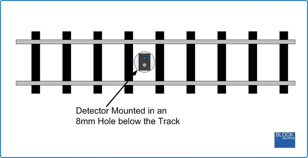
5 rapid flashes. The programming is then complete and the module will restart. If you make a mistake programming, simply repeat the process. Performing a factory reset will reset the sensitivity setting back to 5. Installation The Infra-Red sensor is normally installed below the track-bed. The detection range of the unit is up to approximately 25mm from the face of the package when normal sensitivity is set (for dark surfaces with low levels of reflectivity). The detector can be mounted in an 8mm hole drilled through the track baseboard. If required, the detector can be held in place using a small amount of blutack, expanded polystyrene or similar. The led diameter is 2.2mm, so on smaller scales the leds can still have a clear view between the sleepers.
6

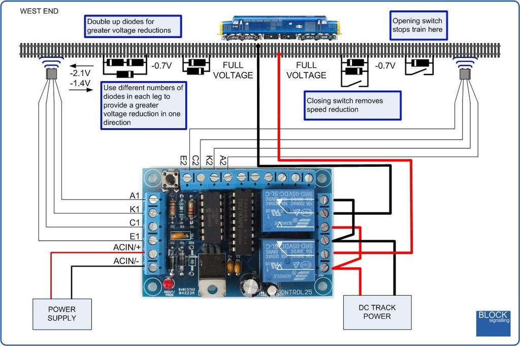
7 Wiring - Basic The diagram below shows the connections from the DC Track Power (Throttle) wired via the shuttle module. The two relays on the module control the switching of the polarity of the power feed to the track and hence the direction of the running. Infra-Red sensors are located where it is required to stop the front of the train. As supplied, the controller is set program 3 with a fixed waiting time of 5 seconds at the west end, a fixed waiting time of 10 seconds at the east end. These times can easily be changed. When power is first switched on and the throttle is opened, the train will travel from west to east until it is detected by sensor 2, when it will be halted. After 10 seconds of waiting time, the module will reverse the track polarity and the engine will run back towards the west end until it is detected by sensor 1, when it will be stopped. At the west end, it will wait 5 seconds and then the process will repeat.
8 Setting the Waiting Times Each of the times can be set from 1 second to 240 seconds. The west end waiting time is set with setting 4 and the east end waiting time is set with setting 6. For instance, if you want to set the west end maximum waiting time to 20 seconds, switch off the power to the module and hold down the Push Button. Apply the power and continue holding the push button until 4 flashes of the led are seen. At this point, release the button. You will see a long flash of five seconds. The led will begin flashing again. When you have seen 20 flashes (for 20 seconds waiting time), press the button. You will see a long flash of five seconds and then 10 rapid flashes. The programming is then complete and the will start running the program. If you make a mistake programming, simply repeat the process. Random Waiting Times If instead of fixed waiting times, random waiting times are preferred, then settings 5 and 7 can be changed. For instance, setting 5 selects the west end waiting time to either fixed or random. Setting 7 changes the waiting time at the east end. If random waiting time is selected, the minimum waiting time will be approximately 1/4 of the maximum waiting time set. The maximum waiting time that can be programmed is 240 seconds. To select random timing, switch off the power to the module and hold down the Push Button. Apply the power and continue holding the push button until 5 flashes of the led are seen. At this point, release the button. You will see a long flash of five seconds. The led will begin flashing again. When you have seen 2 flashes (setting random timing as the selected option), press the button. You will see a long flash of five seconds and then 10 rapid flashes. The programming is then complete and the will start running the program. If you make a mistake programming, simply repeat the process.

9 Wiring - Control Panel Route Leds Optional additional leds may be connected to show the operation of the module. These will be lit when there is a train waiting at the west end of the line, when a train is travelling from the west end of the line to the east, when there is a train waiting at the east end of the line, and when there is a train travelling from east to west. Alternatively two-aspect signals can be connected to these outputs. These will remain at red when a train is stationed at the end of the track and will switch to green five seconds before a train departs. After the train has set off, the signal will return to red five seconds later.

10 To select control panel leds or route signals, setting 8 can be changed. Setting it to 1 selects route led indications, and setting it to 2 selects the signal mode. For instance, to select signal mode, switch off the power to the module and hold down the Push Button. Apply the power and continue holding the push button until 8 flashes of the led are seen. At this point, release the button. You will see a long flash of five seconds. The led will begin flashing again. When you have seen 2 flashes, press the button. You will see a long flash of five seconds and then 10 rapid flashes. The programming is then complete and the will start running the program. If you make a mistake programming, simply repeat the process. Connecting Leds When using leds it is important to connect them the right way around. The negative lead (cathode) is identified by a flat on the side of the led body, and by having a shorter lead.
11
12 Program Flow Diagram The diagram below shows all the programming options.

13 Other Ideas Trains can be operated at different speeds by inserting one or more diodes in the feed to the track. Each diode has an approximate 0.7V voltage drop. Use a different number of diodes in each direction to create different speeds in each direction. You need at least one diode for each direction. Creating additonal track gaps, with associated diodes, allows diffeing voltages along a length of track, and so different operating speeds in each section. Use one diode in each direction to drop the speed in the following section by equal amounts. Use a different number of diodes in each direction to create different speeds in each direction. You need at least one diode for each direction. Speed reductions can be removed by shorting across the diodes with a switch. Different stop points can be created by inserting additional single diodes, and shorting across them when they are not required.
14
LEVEL CROSSING MODULE FOR LED SIGNALS LCS2
 LEVEL CROSSING MODULE FOR LED SIGNALS LCS2 Fully Flexible Controller for Common-Anode LED signals Automatically detects trains using an infra-red sensor mounted below the track bed Operates attached yellow
The UK sequence is shown below. The duration of each phase can be easily adjusted during the programming to suit.
 The Traffic Light Controller has been designed to replicate the traffic light sequence as used in the UK and on the continent for junction control and road-works. The UK sequence is shown below. The duration
POINTS POSITION INDICATOR PPI4
 POINTS POSITION INDICATOR PPI4 Monitors the brief positive operating voltage across points motors when they are switched Lights a corresponding led on a control panel to show the last operation of each
BLOCK OCCUPANCY DETECTOR
 BLOCK OCCUPANCY DETECTOR This Block Occupancy Detector recognises the current drawn by moving trains within a block, and can operate a number of built-in programs in response. When used with DC systems,
Azatrax Model Railroad Track Signal Control - Single Track
 Installation Guide Azatrax Model Railroad Track Signal Control - Single Track TS2 What it is: The TS2 operates one or two trackside block signals (one in each direction) on one track to simulate the block
STX Stairs lighting controller.
 Stairs lighting controller STX-1795 The STX-1795 controller serves for a dynamic control of the lighting of stairs. The lighting is switched on for consecutive steps, upwards or downwards, depending on
Projector Lift. User Guide INSTALLATION OPERATION SETUP PROGRAM IR REMOTE FACTORY RESET
 INSTALLATION OPERATION SETUP PROGRAM IR REMOTE FACTORY RESET MODELS: Small - Standard Deep - Wide - Large X-Large - XX-Large Projector Lift User Guide ver 26.01.012 2012 PureTheatre CONTENTS Part Checklist...
Access Control Keypad for MK-DV, JB-DV
 #91173 0406 Access Control Keypad for MK-DV, JB-DV - INSTRUCTIONS - The KVI is a surface mount electronic access control keypad for use with Aiphone s MK-DV or JB-DV video door station. Designed with the
SECU-16. Specifications Power: Input Voltage 9-12V DC or AC Input Current Max 200mA. 8 2-wire inputs, Analog (0 5VDC) or Supervised
 or Supervised") SECU-16 Introduction The SECU-16 module allows 8 inputs and 8 low-current relay outputs to be added to an ADICON control system. The inputs may be supervised (switch closure), analog, or 4-20mA. Specifications
SECU-16 Introduction The SECU-16 module allows 8 inputs and 8 low-current relay outputs to be added to an ADICON control system. The inputs may be supervised (switch closure), analog, or 4-20mA. Specifications
Luminaire installation box Surface-mounted box Ceiling installation box
 -Smart PTM Ambient light sensor and motion detector for constant lighting control uminaire installation box Surface-mounted box Ceiling installation box Overview: -SMART PTM i is an ambient light sensor,
Light Emitting Diodes (LEDs)
") Light Emitting Diodes (LEDs) Example: Circuit symbol: Function LEDs emit light when an electric current passes through them. Connecting and soldering LEDs must be connected the correct way round, the diagram
Light Emitting Diodes (LEDs) Example: Circuit symbol: Function LEDs emit light when an electric current passes through them. Connecting and soldering LEDs must be connected the correct way round, the diagram
Technology Control Technology
 L e a v i n g C e r t i f i c a t e Technology Control Technology P I C A X E 1 8 X Prog. 1.SOUND Output Prog. 3 OUTPUT & WAIT Prog. 6 LOOP Prog. 7...Seven Segment Display Prog. 8...Single Traffic Light
ImproX (TRT) Twin Remote Terminal INSTALLATION MANUAL
 Twin Remote Terminal INSTALLATION MANUAL") SPECIFICATIONS MODEL NUMBER: XRT910-0-0-GB-XX XRT911-0-0-GB-XX XTT911-0-0-NN-XX IMPROX TRT ImproX (TRT) Twin Remote Terminal INSTALLATION MANUAL Working Environment XRT910-0-0-GB-XX... (Aluminium Extruded
SPECIFICATIONS MODEL NUMBER: XRT910-0-0-GB-XX XRT911-0-0-GB-XX XTT911-0-0-NN-XX IMPROX TRT ImproX (TRT) Twin Remote Terminal INSTALLATION MANUAL Working Environment XRT910-0-0-GB-XX... (Aluminium Extruded
21 Channel Light Show PWM LED Controller with Remote Control
 21 Channel Light Show PWM LED Controller with Remote Control Application: Managing dynamic illuminated advertising signs, spectacular light walls, podiums, etc. Managing groups LED and LED strips - from
Sensor module. Safety instructions. Function Correct use. Product characteristics. Structure of the device. Operation. Ref.No.
 Sensor module Ref.No.: SM 1608 V03 Safety instructions Caution! Electrical devices may only be installed and fitted by electrically skilled persons. Non-compliance with the installation information could
Product information. Front-door station series with video for surface-mount
 Product information Front-door station series with video for surface-mount series VPES series VPDS 2 05/2006 Table of contents Scope of delivery...3 Safety notices...3 General notes on the cabling in TCS
8 PIN PIC PROGRAMMABLE BOARD (DEVELOPMENT BOARD & PROJECT BOARD)
") ESSENTIAL INFORMATION BUILD INSTRUCTIONS CHECKING YOUR PCB & FAULT-FINDING MECHANICAL DETAILS HOW THE KIT WORKS LEARN ABOUT PROGRAMMING WITH THIS 8 PIN PIC PROGRAMMABLE BOARD (DEVELOPMENT BOARD & PROJECT
ESSENTIAL INFORMATION BUILD INSTRUCTIONS CHECKING YOUR PCB & FAULT-FINDING MECHANICAL DETAILS HOW THE KIT WORKS LEARN ABOUT PROGRAMMING WITH THIS 8 PIN PIC PROGRAMMABLE BOARD (DEVELOPMENT BOARD & PROJECT
PROXIMITY SWITCHES INDUCTIVE TUBULAR SENSOR M30 SERIES HIGHLIGHTS APPLICATIONS
 INDUCTIVE TUBULAR SENSOR M30 SERIES There are millions of inductive sensors deployed in almost every area of factory automation. They detect metal objects contactless and are distinguished by a long operating
LEDs. Types and Uses. By Wil Davis June 18, 2016
 LEDs (Light Emitting Diodes) Types and Uses By Wil Davis June 18, 2016 Definition Commonly called LEDs. Found every where Basically, LEDs are like tiny light bulbs that fit easily into an electrical circuit.
SU17 Series Fiber Optic Sensors
 SU17 Series Fiber Optic Sensors Fiber Optic Diffuse and Thru-Beam Mode See page 750 Sensing Range: Determined by fiber optic cable Output: NPN, PNP Built-in auto-tuning Digital display Mutual interference
RF Wireless Receiver (Model S4PU-DC-ANT3)
") RF Wireless Receiver (Model 0020445 S4PU-DC-ANT3) Package Include: 1 Reciver S4PU-DC06-ANT3 / S4PU-DC09-ANT3 / S4PU-DC12-ANT3 / S4PU-DC24-ANT3 1 User Manual Feature: Application: It can be used in industry
RF Wireless Receiver (Model 0020445 S4PU-DC-ANT3) Package Include: 1 Reciver S4PU-DC06-ANT3 / S4PU-DC09-ANT3 / S4PU-DC12-ANT3 / S4PU-DC24-ANT3 1 User Manual Feature: Application: It can be used in industry
HS-509 VIBRATION TRIP MODULE
 HS-509 VIBRATION TRIP MODULE 1. Overview The HS-509 is a configurable trip amplifier capable of accepting a 4-20mA signal from a HS-420 sensor and providing two trip action relay outputs along with an
APPLICATIONS. Automatic warehouse. Trasportation lines
 INDUCTIVE TUBULAR SENSOR M8 SERIES There are millions of inductive sensors deployed in almost every area of factory automation. They detect metal objects contactless and are distinguished by a long operating
Building the BX24-AHT
 Building the BX24-AHT file:///f /LASER/build-it.htm (1 of 8) [03/04/2002 5:21:52 PM] file:///f /LASER/build-it.htm (2 of 8) [03/04/2002 5:21:52 PM] Tips & Tricks Use a 25W or smaller soldering iron with
Timer Modules. MEU11 24 Hour Module, MEU17 7 Day Module (Without Housing)
") Timer Modules MEU11 24 Hour Module, MEU17 7 Day Module (Without Housing) EMU11 24 Hour Module, EMU17 7 Day Module (With Housing Giving panel mounting facility) Installation & Operating Instructions 1 1.
Timer Modules MEU11 24 Hour Module, MEU17 7 Day Module (Without Housing) EMU11 24 Hour Module, EMU17 7 Day Module (With Housing Giving panel mounting facility) Installation & Operating Instructions 1 1.
Bill of Materials: Super Simple Water Level Control PART NO
 Super Simple Water Level Control PART NO. 2169109 Design a simple water controller in which electrodes are required to sense high and low water levels in a tank. Whenever the water level falls below the
Atlas Drop In Decoder
 TCS DCC decoders provide the ultimate in control. This decoder is in # A1 Atlas Drop In Decoder 1.3 amp continuous, 2.0 amp peak motor drive plus four 100 ma function outputs Dither creates the ultimate
7 SEGMENT LED DISPLAY KIT
 ESSENTIAL INFORMATION BUILD INSTRUCTIONS CHECKING YOUR PCB & FAULT-FINDING MECHANICAL DETAILS HOW THE KIT WORKS CREATE YOUR OWN SCORE BOARD WITH THIS 7 SEGMENT LED DISPLAY KIT Version 2.0 Which pages of
Troubleshooting. 1. Symptom: Status indicator (Red LED) on SSR is constant on. 2. Symptom: Output indicator (Yellow LED) on SSR is flashing.
 on SSR is constant on. 2. Symptom: Output indicator (Yellow LED) on SSR is flashing.") Product Data Electrical Data SST (Transmitter) SSR (Receiver) Supply voltage 18 30 V dc Max. Voltage ripple 15 % (within supply range) Current consumption 100 ma (RMS) 75 ma Digital - 100 ma Max. outputs
Product Data Electrical Data SST (Transmitter) SSR (Receiver) Supply voltage 18 30 V dc Max. Voltage ripple 15 % (within supply range) Current consumption 100 ma (RMS) 75 ma Digital - 100 ma Max. outputs
FOREST SHUTTLE S / L / M RECEIVER
 2 FOREST SHUTTLE S / L / M RECEIVER QUICK INSTALLATION OF ASSEMBLED TRACKS : Programming Shuttle S / L / M Receiver to a channel One pre-assembled motorized curtain track systems is standard programmed
ADD AN AUDIO MESSAGE TO YOUR PRODUCT WITH THIS RECORD & PLAYBACK KIT
 ADD AN AUDIO MESSAGE TO YOUR PRODUCT WITH THIS RECORD & PLAYBACK KIT BUILD INSTRUCTIONS Before you start take a look at the Printed Circuit Board (PCB). The components go in the side with the writing on
CSM Color sensors. Color sensors for the detection of a single color in restricted space conditions
 CSM Color sensors Color sensors for the detection of a single color in restricted space conditions Due to its compact design, the CSM can be used in the most confined of spaces. The choice of color tolerance
16 Amp Electronic 24 Hour/7 Day Time Controller
 16 Amp Electronic 24 Hour/7 Day Time Controller Model: ELU56 Installation & Operating Instructions 1 1. General Information These instructions should be read carefully and retained for further reference
Electrical connection
 Splice sensor Dimensioned drawing en 04-2014/06 50116166-01 4mm 12-30 V DC We reserve the right to make changes DS_IGSU14CSD_en_50116166_01.fm Reliable detection of splice on paper web or plastic web With
MSS-CASCADE User Manual
 MSS-CASCADE User Manual Overview The MSS-CASCADE module is designed to provide basic ABS signaling functionality at a block boundary as part of a Modular Signal System implementation ( http://modularsignalsystem.info/
Assembly. Front view. LEDs. Parametrization interface. Power Bus
 otation Speed Monitor Features Assembly 1-channel signal conditioner 2 V DC supply Input for 2- or -wire sensors Input frequency 10 mhz... 50 khz elay contact output Start-up override and restart inhibit
Amplifier for fiber optics. Dimensioned drawing
 Amplifier for fiber optics Dimensioned drawing up to 525mm up to 120mm 10-30 V DC 3-digit display for indicating and setting the switching threshold NEW: AutoSet function for easy sensor adjustment Menu
Film-Tech. The information contained in this Adobe Acrobat pdf file is provided at your own risk and good judgment.
 Film-Tech The information contained in this Adobe Acrobat pdf file is provided at your own risk and good judgment. These manuals are designed to facilitate the exchange of information related to cinema
RADIO RECEIVER RGBW CONTROLLING LED STRIP COMMON ANODE
 TELECO AUTOMATION SRL - Via dell Artigianato, 16-31014 Colle Umberto (TV) ITALY TELEPHONE: ++39.0438.388511 FAX: ++39.0438.388536 - www.telecoautomation.com This document is the property of Teleco Automation
P Triply ingenious Portier
 P109465 Triply ingenious Portier Ultra-slim design Easiest possible installation Maximum functionality 2 Portier modular door station The new and distinctive design of our modular Portier door station
APPLICATIONS. Automatic warehouse. Trasportation lines
 INDUCTIVE TUBULAR SENSOR M12 SERIES There are millions of inductive sensors deployed in almost every area of factory automation. They detect metal objects contactless and are distinguished by a long operating
7 Day Digital Time Switch
 7 Day Digital Time Switch Model: NTT08 Installation & Operating Instructions 1 1. General Information These instructions should be read carefully and retained for further reference and maintenance. 2.
Setting up the Setting up the Dragonfly 1 v June
 Setting up the 1 Introduction In this guide we'll be setting up a rather complete observatory, integrating in the Dragonfly all relevant elements: Roof, motorized with a garage-door system and including
INSTALLATION INSTRUCTIONS FOR
 INSTALLATION INSTRUCTIONS FOR MODEL 2240LED www.sportablescoreboards.com 1 Table of Contents 8 X 7 INDOOR SCOREBOARD... 3 THE SCOREBOARD SYSTEM SHOULD INCLUDE THE FOLLOWING PARTS:... 3 INSTRUCTIONS FOR
RADIO RECEIVER RGB CONTROLLING LED COMMON KATHODE
 RADIO RECEIVER RGB CONTROLLING LED COMMON KATHODE Product code: TVRGBDSYA0 Syncroled Master receiver 0mA TVRGBDSYM0 Syncroled receiver 0mA TVRGBDSYB0 Syncroled Master receiver 00mA TVRGBDSYN0 Syncroled
"Sophisticated Model Railroad Electronics"
 LOGIC RAIL TM "Sophisticated Model Railroad Electronics" TECHNOLOGIES 21175 Tomball Pkwy Phone: (281) 251-5813 Suite 287 email: info@logicrailtech.com Houston, TX 77070 http://www.logicrailtech.com Block
multi-function meters
 multi-function meters eclipse 2 eclipse 7 installation and operating manual 1 GENERAL DESCRIPTION 2 INSTALLATION 3 WIRING INFORMATION 4 2 ECLIPSE 2 METERS 2.1 PROGRAMMING THE METER 5 2.2 INFORMATION 6
Radio for Everyone...
 Radio for Everyone... P R O D U C T I O N O N A I R C O N S O L E Eight dual inputs Built in auto Silence detector 4 USB in/out stereo channels Play out USB control section included AES 3 digital program
Single Axis Position Controller
 SERIES P9511 Single Axis Position Controller Compact Construction Simple Go-to operation Integrated Relay Output Integrated Mains Power Supply ELEKTRO-TRADING sp. Z o.o. 44-109 Gliwice, ul. Mechaników
QUAD ENVELOPE MANUAL V.1
 www.malekkoheavyindustry.com 814 SE 14TH AVENUE PORTLAND OR 97214 USA TABLE OF CONTENTS SPECIFICATIONS 1 INSTALLATION 2 DESCRIPTION 3 CONTROLS 4-6 MEASUREMENTS 7 USING QUAD ENVELOPE WITH VARIGATE 8+ AND
3.22 Finalize exact specifications of 3D printed parts.
 3.22 Finalize exact specifications of 3D printed parts. This is the part that connect between the main tube and the phone holder, it needs to be able to - Fit into the main tube perfectly - This part need
Digital Economy Seven Programmer
 Digital Economy Seven Programmer Model: TRTD7N White Installation & Operating Instructions 1. General Information These instructions should be read carefully and retained for further reference and maintenance.
Digital Time Switch. Installation & Operating Instructions
 Digital Time Switch Model: NTT06 24 Hour General Purpose Digital Timer Model: NTT07 7 Day General Purpose Digital Timer Installation & Operating Instructions 1 1. General Information These instructions
Level Measurement silometer FMC 420, FMC 423
 Technical Information TI 077F/00/en Level Measurement silometer FMC 420, FMC 423 For connecting to capacitance probes or Deltapilot S hydrostatic probes Main applications The is used for continuous level
TP7001 Range Electronic 7 Day Programmable Room Thermostat. Danfoss Heating. Installation Guide
 TP7001 Range Electronic 7 Day Programmable Room Thermostat Danfoss Heating Installation Guide For a large print version of these instructions please call Marketing on 0845 121 7400. Certification Mark
Data Sheet. HSMW-C120, HSMW-C130, HSMW-C191, HSMW-C197, HSMW-C265 White ChipLEDs. Description. Features. Applications
 HSMW-C12, HSMW-C13, HSMW-C191, HSMW-C197, HSMW-C265 White ChipLEDs Data Sheet Description These white ChipLEDs come in unique shades of white and provide product differentiation for backlighting application.
Features. Applications
 HSMF-C118 TriColor ChipLED Data Sheet Description The HSMF-C118 tricolor chip-type LED is designed in an ultra small package for miniaturization. It is the first of its kind to achieve such small packaging
Emergency lighting units EM powerled
 CE CPS 12/15 W ED Driver for AC and DC power supplies Product description ED Driver for mains operation with integrated Simple CORRIDOR FUCTIO (CF) For use in central battery systems For luminaire installation
USER S GUIDE. 1 Description PROGRAMMABLE 3-RELAY LOGIC MODULE
 1 Description The is a programmable 3 relay logic module that may be used for multiple applications, including simple timing, door mounted sensor inhibiting and advanced relay sequencing. The contains
QUIZ BUZZER KIT TEACHING RESOURCES. Version 2.0 WHO ANSWERED FIRST? FIND OUT WITH THIS
 TEACHING RESOURCES SCHEMES OF WORK DEVELOPING A SPECIFICATION COMPONENT FACTSHEETS HOW TO SOLDER GUIDE WHO ANSWERED FIRST? FIND OUT WITH THIS QUIZ BUZZER KIT Version 2.0 Index of Sheets TEACHING RESOURCES
Gazer VI700A-SYNC2 and VI700W- SYNC2 INSTALLATION MANUAL
 Gazer VI700A-SYNC2 and VI700W- SYNC2 INSTALLATION MANUAL Contents List of compatible cars... 3 Package contents... 4 Special information... 6 Car interior disassembly and connection guide for Ford Focus...
SceneStyle2 User Guide
 SceneStyle2 User Guide Mode Lighting (UK) Limited. The Maltings, 63 High Street, Ware, Hertfordshire, SG12 9AD, UNITED KINGDOM. Telephone: +44 (0) 1920 462121 Facsimile: +44 (0) 1920 466881 e-mail: website:
Channel Controller for Light Show with Remote Control. HomLiCon RCL164R
 16 + 4 Channel Controller for Light Show with Remote Control Application: Managing dynamic illuminated advertising signs, spectacular light walls, podiums, etc. Managing groups of lamps 120V/60Hz or 230V/50Hz
Dimensions. Model Number. Electrical connection. Features. Pinout Product information. Indicators/operating means. LGS25 Serie.
 Q Dimensions Transmitter Detection field + 9. Detection field 7.8 n Beam. Beam Receiver III 0. 0 Fix H H H Fn Model Number Light grid with fixed cable with -pin, M x connector, and fixed cable with 8-pin,
C-net WIND. User s Guide
 C-net WIND User s Guide EMC Directive 89/336/EEC This product has been designed to be compliant with the above EMC Directive. Maximum performance and compliance with the EMC Directive can only be ensured
45 mm : all channels. Output indicator Yellow LED System status indicator Light source Infrared (880 nm) Opening angle +/ 4 Emission angle +/ 5
 Opening angle +/ 4 Emission angle +/ 5") SPACEGUARD SERIES Description 1-12 metre sensing range 16 to 56 parallel scanning beams Active height of 0 mm to 2520 mm Detector length of 1928 mm to 2648 mm 3 different channel placement models Cable
SPACEGUARD SERIES Description 1-12 metre sensing range 16 to 56 parallel scanning beams Active height of 0 mm to 2520 mm Detector length of 1928 mm to 2648 mm 3 different channel placement models Cable
Data Sheet. HSMx-C280. Miniature ChipLED. Features. Description. Applications. Device Selection Guide
 HSMx-C28 Miniature ChipLED Data Sheet Description The HSMx-C28 ChipLEDs are designed to 42 (1. x.5 mm) industry standard footprint. They are extremely small in size and the low.4 mm height makes them very
Emergency lighting units EM powerled
 E 15 W CE CPS ED Driver for AC and DC power supplies Product description ED Driver for mains operation with integrated Simple CORRIDOR FUCTIO (CF) For use in central battery systems For luminaire installation
Gamma instabus. Technical product information
 Gamma instabus Technical product information Universal dimmer N 554D31, 4 x 300 VA / 1x 1000 VA, AC 230 V Universal dimmer N 554D31 Control of dimmable lamps, including LED without minimum load Output
Provides an activation of Relay 1 triggered by Input 1. The function also provides an option for reverse-logic on the activation of Input 1.
 USER S GUIDE PROGRAMMABLE 3-RELAY LOGIC MODULE 1 Description The is a programmable 3 relay logic module that may be used for multiple applications, including simple timing, door mounted sensor inhibiting
CAMTO LTD. Arc detecting system DC/AC
 CAMTO LTD Arc detecting system DC/AC Arc detecting system DC/AC The system is based on experience with arc protection since 1962. The system units are built into boxes that all fit on a 35 mm DIN-rail.
INSTALLATION AND OPERATION M
 INSTALLATION AND OPERATION M RUBYSTAR INSTALLATION AND OPERATION MANUAL Safety Instructions : Only authorised installers should install and or replace Rubystar inverters. Ensure that all electrical installations
Nixie Clock Type Quattro'
 Assembly Instructions And User Guide Nixie Clock Type Quattro' - 1 - Issue Number Date REVISION HISTORY 2 8 Sept 2012 Errors corrected 1 27 July 2012 New document Reason for Issue - 2 - 1.1 Nixie Quattro
M-relays, 2, 3 or 4 pole, 7-12 A Datasheet
 , 2, 3 or 4 pole, 7-12 A Datasheet Features Compact plug-in design 2, 3 or 4 C/O contacts Standard mechanical indicator Flat and silver relay pins for excellent connection in socket Wide range sockets
SCENEMASTER 3F QUICK OPERATION
 SETTING PRESET MODE SCENEMASTER 3F QUICK OPERATION 1. Hold [RECORD], and press [CHNS] (above the Channels Master) to set Scenes, Dual, or Wide mode. WIDE MODE OPERATION In Wide mode, both CHANNELS and
Electrical connection
 (I)GSU 14C Ultrasonic Label Fork Dimensioned drawing en 06-2011/12 50109234-01 4mm 12-30 V DC 4 m/s We reserve the right to make changes DS_IGSU_14C_en.fm Ultrasonic forked sensor for universal application
Data Sheet. HSMR-CL mm Blue Leadframe-Based Surface Mount ChipLED. Features. Description. Advantages. Package Dimensions
 HSMR-CL25.25mm Blue Leadframe-Based Surface Mount ChipLED Data Sheet Description The HSMR-CL25 series of parts is designed with an ultra small form factor to allow this miniaturization. The HSMR- CL25
Features. Applications
 HSMx-C1/C177/C197/C265 High Performance Chip LEDs Data Sheet Description These chip type LEDs utilize Aluminium Indium Galium Phosphide (AlInGaP) material technology. The AlInGaP material has a very high
Caution. Hanging the Screen:
 Installation Instructions for Laminar and Laminar XL Projection Screens Caution 1. Read Instructions through completely before proceeding; keep them for future reference. Follow these instructions carefully.
randomrhythm Bedienungsanleitung User Guide
 randomrhythm Bedienungsanleitung User Guide EN Foreword Whether random really exists or is just an illusion, shall be discussed by philosophers and mathematicians. At VERMONA, we found a possibility to
SPACESCAN SERIES SS 02
 Description 0-10 metre sensing range 12 to 384 channels Available with channel spacing of 5, 10 or 20 mm Active length of 225 mm to 1920 mm Housing length of 300 mm to 1980 mm Plug connection 18-30 V dc
LED Driver Linear / area dimming. Driver LCAI 38/75W TW lp Tunable White
 Driver LCAI 38/75W TW lp Tunable White Product description 2-channel LED Driver with LI DT8 Output power: 38 W or 75 W Power input on standby < 0.3 W Nominal life-time up to 50,000 h 5-year guarantee Properties
Technical data. General specifications. Indicators/operating means
 Model Number Single head system Features Sensor head bidirectional and rotatable Function indicators visible from all directions Quick mounting bracket Selectable sound lobe width Programmable Diagrams
Technical data. General specifications. 60 ma Power consumption P 0. 1 W Time delay before availability t v. 120 ms Interface. Protocol IO-Link V1.
 Model Number Single head system Features IO-link interface for service and process data Programmable via DTM with PACTWARE programmable switch outputs Selectable sound lobe width Synchronization options
>Inductive. REFERENCE guide. Proximity
 >Inductive REFEREE guide Proximity DATALOGIC: SOLUTIONS FOR INDUSTRIAL AUTOMATION Datalogic Industrial Automation is an industry-leader in products and solutions for material handling, traceability, inspection
relays Electromechanical 2006 /2007
 1 Electromechanical relays 2006 /2007 miniature relays industrial relays automotive relays interface relays plug-in sockets and accessories 2 Relays and Sensors - our business! Established in 1935 to manufacture
LED Backlight for Technics amplifiers
 LED Backlight for Technics amplifiers Technics SE-A900S Technics SE-A900SM2 Technics SE-A909S Technics SE-A1000 Technics SE-A1000M2 Technics SE-A1010 Rev. 1.2 B Description The LED module is designed to
Nixie Clock Type Frank 2 Z570M
 Assembly Instructions And User Guide Nixie Clock Type Frank 2 Z570M Software version: 7R PCB Revision: 11 April 09-1 - 1. INTRODUCTION 1.1 About the clock Nixie clock type Frank 2 is a compact design with
263 Series LED Bargraph Indicator and Controllers
 263 Series LED Bargraph Process Control Water Treatment High resolution 51 segment LED Bargraph for easy reading Accuracy 1% Red display Vertical or Horizontal mounting & stackable Connection Diagrams
Monday 28 January 2013 Morning
 Monday 28 January 2013 Morning GCSE DESIGN AND TECHNOLOGY Electronics and Control Systems A514/01 Technical Aspects of Designing and Making: Electronics *A528620113* Candidates answer on the Question Paper.
Seth h N eu N mann 1
 Seth Neumann sneumann@pacbell.net 1 Why Control Panels? Panels work well where you have a group of related indicators and controls close together Panels may not be the right answer for all fascia controls:
Dear Railway Modeller,
 1721_Betra_21_6915_0101.qxd 27.09.2007 12:15 Uhr Seite 25 6915 TURN-CONTROL Turntable Controller Contents Operating instructions GB Page 1. Safety Warnings and Advice on Use 26 1.2. Components, operational
Electrical connection
 Colour sensors Dimensioned drawing Part No. 50109619 12.5mm 60mm 10-30 V DC 6 khz Scanner for colour detection Very short response time 85µs for detection of fast or small objects and marks Direct indication
4.0 Description. 2-channel operation D1 and D2 rated at 200 VA each. 1-channel operation D1 rated at 400 VA (see connection chap. 6.
 _307 238_EN_LUXOR 405_310 410 01_D.qxd 21.09.16 10:54 Seite 1 Operating Manual Dimmer module 4050100 1.0 Designated use The LUXOR dimmer module expands the existing LUXOR series of devices. It switches
Art M Digital codelock module
 CODELOCK UNIT MODULES Art. 4900-4900M This module has on the front a 12 stainless steel button keypad (keys from 0 to 9 plus ENTER and CLEAR keys), 2 LEDS for operation signalling, the keypad illumination
TDEPD. Field-Programmable Pressure Switch/Transducer with Integrated LED Display. Programming Sequence Manual
 TDEPD Field-Programmable Pressure Switch/Transducer with Integrated LED Display Programming Sequence Manual Wiring Diagram Pin5 Maintenance Mode + Gray Vent Pin2 Digital Output 2 +/ Analog Output + White
LED control gear Compact dimming. Uconverter LCAI 2x38 W 0500 K013 one4all ECO series. Ordering data
 Product description Dimmable built-in for LED Constant current (with 2 adjustable output channels) Designed for outdoor and street luminaire Output power 2 x 38 W Suitable for mains voltage peaks (burst/surge)
Speed sensor MiniCoder GEL 2471
 Speed sensor MiniCoder GEL 2471 for electrically conducting toothed-wheels Technical information version 10.02 The MiniCoder family from Lenord + Bauer offers spacesaving solutions for the contactless
Data Sheet. HSMx-C120, HSMx-C177, HSMx-C197 and HSMx-C265. High Performance Chip LEDs. Description. Features. Applications. Device Selection Guide
 HSMx-C12, HSMx-C177, HSMx-C197 and HSMx-C265 High Performance Chip LEDs Data Sheet Description These chip type LEDs utilize Aluminium Indium Galium Phosphide (AlInGaP) material technology. The AlInGaP
Features. Applications R TOP VIEW
 ASMT-CW InGaN White,.4mm Low Profile Right Angle Surface Mount ChipLED Data Sheet Description The ASMT-CW of white color chip-type LEDs is designed with the smallest footprint to achieve high density of