Seth h N eu N mann 1
|
|
|
- Oliver Malone
- 5 years ago
- Views:
Transcription
1 Seth Neumann 1
2 Why Control Panels? Panels work well where you have a group of related indicators and controls close together Panels may not be the right answer for all fascia controls: for example turnout controls may better be placed opposite the turnout being controlled to facilitate walk around operation. 2
3 Why this clinic? Dave Connery (IHX Clinic Chairman) requested a clinic on the panels on my Union Pacific in Niles Canyon after a visit on a recent PCR tour These techniques were developed by Rick Fortin and Kermit Paul but I have expanded and adapted them for my layout: they are reasonably easy to build and inexpensive to make so they may find a place on your layout, too! 3


4 Examples Radum Panel 4
5 Pleasanton Panel 5

6 Staging Panel 6


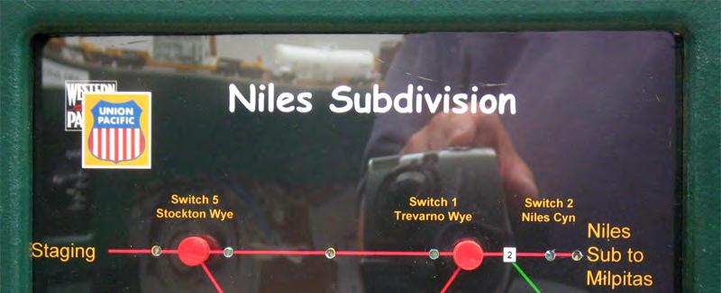
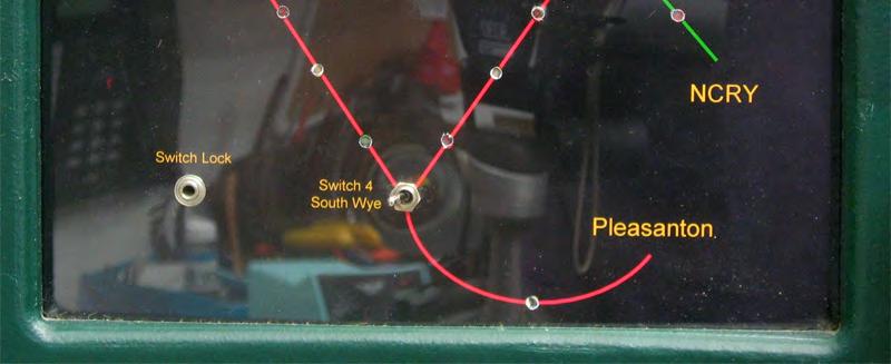
7 Problem: Messy set of controls for Diridon Station The labels on the fascia don t look so great and the Signal Repeater is in another location so the operator has to look around to get his train in or out of staging 7


8 Solution: A Unified Panel 8
9 How to Make the Artwork? Any graphics program will do, so you use this technique with your favorite drawing, painting or CAD program I used PowerPoint because I used it a lot in my career as a Product Manager and it is very fast for this sort of work: Draws lines and basic shapes Has libraries of useful shapes and graphics Import pictures in many formats Is included in most versions of Microsoft Office Most presentation programs have similar capabilities 9
10 Start with lines to represent Track Hints: you can lock lines to horizontal & vertical by holding the shift key as you draw them You can copy lines (Ctrl C) and paste them (Ctrl V) Use the align tool to keep things lined up 10
11 Change Line Colors and Widths Hints: I use 2 ¼ for main tracks I use Red for main track and green for other tracks These tools are in the Shape Outline submenu in the drawing menu 11
12 Add the Dots for Indicators Occupancy Place holder for toggle switch Switch position indicator: Green for normal Red for reversed End of Track 12
13 Add the Signals Hints: Signals made from circles and rectangles 13
14 Set The Background And Remove Any Distracting Graphics 14
15 Add Text and Other items Milpitas CPM019 Berryessa Diridon Station Stop when lit 15


16 Milpitas CPM019 Berryessa Diridon Station Stop when lit 16

17 Milpitas CPM019 Milpitas CPM019 Diridon Station Diridon Station Berryessa Stop when lit Berryessa Stop when lit Rotate 90 Degrees to get two copies 17
18 Print a test copy for sizing I use a basic black and white print for this phase Check size against the place where the panel is to go Check that your panel material fits I use two pieces of Plexiglas: 1/8 for the back and 1/16 for the cover You can add registration marks to your graphic for fitting 18

19 Cut your Material to Fit Leave a little extra if you re inserting from behind the fascia as I did 19

20 Drill Registration And Switch Holes I use sub-miniature toggle switches which are 5/16 diameter and have a barrel about.200 deep Use a test print out to locate the holes Registration Hole Registration Hole 20


21 Drill LED Holes in the Back Sheet Only A 3 mm LED takes a #35 bit but I use the high speed bits from TAP plastics: 1/8 is pretty close Use a test print out as a drilling guide Use a drill press or, better yet, a drill press with an XY table or a mill if you have access to one 21


22 Print Out the Final Panel Graphic Use Plastic Photo Paper this is like photo paper but it s on 7 mil plastic. It won t rip under the drill like paper and it s dimensionally stable and won t suck in moisture and pucker over time I used Inkpress White Gloss Film from InkJetArt.com, last I checked, 20 sheets go for $30 or $1.50 a sheet 22
23 Use The Back Panel As A Drill Template For The Graphic No photo 23
24 Assemble the Sandwich Remove the blue protective film from all surfaces except the front of the front panel Front Panel Completed Graphic with holes for LEDs and Switches Back panel Use machine screws through the registration holes to keep everything aligned Mark the holes on the back for the color LED needed, it s OK to mark with Sharpies as this won t be seen. Check that the holes are correctly labeled. Ask me why <g>. 24
25 Prepare the LEDs This is Rick Fortin s Trick: the LEDs have a ring at the base that holds them against the 1/8 back panel but the LED are too long to seat, however you can file or sand them flat and shorter for a better fit. File down to here 25
 up or down for easier wiring Leave it alone to set up for a few hours")
26 Glue the LEDs in I use E6000 from TAP Plastics Keep the LEDs aligned with all long leads (anode) up or down for easier wiring Leave it alone to set up for a few hours 26
27 Wire the LEDs I like to wire my LEDs with all of the Anodes together and bussed to +5. You may have a different standard. This allows the LEDs to be driven by open collector or open drain drivers (like CMRI) Be sure to add an appropriate limiting or ballast resistor The example panel will be driven by an Arduino but I haven t settled on the exact circuit yet. In this case it may not need limiting resistors so I didn t install them. 27


28 LEDs with Power Bussed Together I use a wire wrap tool to wrap the wire to the leads and then solder over. I cut the leads off the anodes at about ½ You may need a different arrangement depending on your wiring requirements 28
29 LED Terminology And Wiring Modern LEDs will light brightly with as little as 2 or 3 ma so very little current is involved Forward voltage (on package) is typically 1.5 V (Red) 3.1 V (White) Anode, + end, long lead + 5 VDC Cathode, - end, short lead R To Determine R: Subtract Forward voltage of Diode from Supply: (white LED) = 1.9 Desired current = 5mA, so given Ohm s law R= Volts/Current or 1.9/.005 = 380. The nearest standard value is 390, so we use a 390 ohm Resistor To get a wattage rating, Watts = Volts X Current so we have 1.9V x.005a = ~.001 W, so an 1/8 th Watt (or larger) resistor will more than do 29


30 LED Package Info 30

31 Diodes and Resistors I got these at the components aisle at Fry s Light Emitting Diodes were 10 for $3 ¼ W Resistors were 10 for $1 Also try Halted, Anchor or any of Mousser, Jameco, Digikey etc 31


32 Cheap and Dirty LED Tester A 9V battery with a 1K ohm resistor on the + terminal wired in series with a test lead and another test lead to ground. Limits current to about 9 ma Actual current to diode under test is from 6 8 mawhich is safe for anything you need If the LED under test doesn t light, try flipping polarity. If it still doesn t light it s probably blown. 32
33 Now For Something Completely Different Signal Repeaters This appeared in the Branch Line a few years ago and in LDJ in the Planning for Signaling series I had set up my signal system but the correct signals were not yet available (long, sad story I hope to have them on the layout by next year) Repeaters allowed me to start CTC operations right away and would help color-blind operators even after the correct US&S type H2 search light signals were installed on the layout. 33

34 Remember those signals at Diridon Station? You can t actually see them because Diridon is hidden staging for the ACE train So I put the repeater up on top of the View Divider Note the signal is a Type D color light, red is on the bottom per railroad practice. This means color-weak guys can read them The low signals have only a RED LED because the most favorable aspect this signal can display is RESTRICTING (flashing Red), because Diridon is not signaled 34


35 PC Board For The Repeater Dave Falkenburg laid this out for me. There are several services that print short run circuit boards and they are relatively inexpensive. These boards cost $15 each a few years ago. It s less now. Note the board can support up to 4 heads in a CTC triad The signal can be assembled right or left handed by flipping it over and stuffing form the side you need Not all LEDs need to be populated on my layout we never use Low Green because the turnouts are assumed to be medium speed and the most favorable aspect they can display is APPROACH 35


36 Now I needed a Cover The Plexiglas technique didn t work for because I couldn t control the drill well enough without an XY table and I didn t want to buy a new drill press and table or a mill Kermit Paul offered the use of his Laser Cutter which is very precise 36


37 And a Box I built boxes out of.040 Styrene and painted them aluminum 37


38 Signal Repeater 38
39 Notes on Laser Cutting The laser engraves on a two level material like we use for Coast Division badges: low power burns away the surface color, high power cuts all the way through The laser cutter wants vector artwork. Kermit uses an older version of CorelDraw, but a quick Google search shows many freeware vector graphics tools. For panels that get handled, Kermit recommends a pebbled material (available at Johnson Plastics in Concord) to avoid finger prints I found that the smoke form the cutting process settled into the texture on my white panels and was very difficult to clean out so I d recommend going with a darker color Since my repeaters are on top of the scenic divider, and won t be handled, I d use the smooth material if I did it again 39
40 Questions? 40
Light Emitting Diodes (LEDs)
") Light Emitting Diodes (LEDs) Example: Circuit symbol: Function LEDs emit light when an electric current passes through them. Connecting and soldering LEDs must be connected the correct way round, the diagram
Light Emitting Diodes (LEDs) Example: Circuit symbol: Function LEDs emit light when an electric current passes through them. Connecting and soldering LEDs must be connected the correct way round, the diagram
Obtained from Omarshauntedtrail.com
 http://www.cindybob.com/halloween/ledlighting/ledspotlights/ Introduction In our 2005 haunt providing 120V AC power to the various lights and props requiring it became a fairly large problem. Extension
Bill of Materials: Super Simple Water Level Control PART NO
 Super Simple Water Level Control PART NO. 2169109 Design a simple water controller in which electrodes are required to sense high and low water levels in a tank. Whenever the water level falls below the
Azatrax Model Railroad Track Signal Control - Single Track
 Installation Guide Azatrax Model Railroad Track Signal Control - Single Track TS2 What it is: The TS2 operates one or two trackside block signals (one in each direction) on one track to simulate the block
Visit the Abrams Railroad Empire at
 1 Visit the Abrams Railroad Empire at http://mywebpages.comcast.net/abrams_railroad/ About Dwarf Signals Definitions A ground mounted signal A low home signal (protecting the entrance of a route or block
SHUTTLE WITH INFRA-RED DETECTION SAS2-IR
 SHUTTLE WITH INFRA-RED DETECTION SAS2-IR Shuttle Model Train Controller with Infra-Red Detection Automatically operates a train backwards and forwards along a single line. Train detection using Infra-red
Tube Cricket Build Guide
 Tube Cricket Build Guide The Tube Cricket is a small-wattage amp that puts out about 1 watt of audio power. With a 12AU7 tube-preamp and a JRC386 power amp, the Tube Cricket gives you great tone in a compact
Build your own: Track Display
 Build your own: Track Display! " #! $% $ & ' $ ' ( ) * +, Track Display Manual 0706 web distribution version Table of Contents Section 1 Page 2 Quick Start Guide -Connecting 2 LEDs to Output #1 -Operating
TECHNOLOGY WILL SAVE US: THE LUMIPHONE
 TECHNOLOGY WILL SAVE US: THE LUMIPHONE This is a step-by-step guide to soldering your own Lumiphone. The equipment you should have at your station: goggles, soldering mat, soldering Iron, solder and side
Lab 7: Soldering - Traffic Light Controller ReadMeFirst
 Lab 7: Soldering - Traffic Light Controller ReadMeFirst Lab Summary The two-way traffic light controller provides you with a quick project to learn basic soldering skills. Grading for the project has been
DEM 9ULNACK 3.4 GHz. PHEMT LNA amplifier complete kit assembly guide
 DEM 9ULNACK 3.4 GHz. PHEMT LNA amplifier complete kit assembly guide SPECIFICATIONS Noise Figure: < 0.8 db Gain: > 15 db Frequency Range: 3400-3500 MHz Input Voltage: 7-16 VDC Description: The 9ULNACK
"Sophisticated Model Railroad Electronics"
 LOGIC RAIL TM "Sophisticated Model Railroad Electronics" TECHNOLOGIES 21175 Tomball Pkwy Phone: (281) 251-5813 Suite 287 email: info@logicrailtech.com Houston, TX 77070 http://www.logicrailtech.com Block
Lab 7: Soldering - Traffic Light Controller ReadMeFirst
 Lab 7: Soldering - Traffic Light Controller ReadMeFirst Lab Summary The two way traffic light controller provides you with a quick project to learn basic soldering skills. Grading for the project has been
ELECTRONIC GAME KIT ESSENTIAL INFORMATION. Version 2.0 BUILD YOUR OWN MEMORY & REACTIONS
 ESSENTIAL INFORMATION BUILD INSTRUCTIONS CHECKING YOUR PCB & FAULT-FINDING MECHANICAL DETAILS HOW THE KIT WORKS BUILD YOUR OWN MEMORY & REACTIONS ELECTRONIC GAME KIT Version 2.0 Build Instructions Before
Los Angeles Model Railroad Society. Assembling Fascia Plates
 Los Angeles Model Railroad Society Assembling Fascia Plates Ira Abramowitz 8/10/2011 1 INTRODUCTION...3 2 FASCIA ELECTRICAL ASSEMBLY...3 2.1 FASCIA WIRING TO BOARDS...4 2 1 Introduction Mike Haasis has
Introduction 1. Green status LED, controlled by output signal ST. Sounder, controlled by output signal Q6. Push switch on input D6
 Introduction 1 Welcome to the GENIE microcontroller system! The activity kit allows you to experiment with a wide variety of inputs and outputs... so why not try reading sensors, controlling lights or
QUIZ BUZZER KIT TEACHING RESOURCES. Version 2.0 WHO ANSWERED FIRST? FIND OUT WITH THIS
 TEACHING RESOURCES SCHEMES OF WORK DEVELOPING A SPECIFICATION COMPONENT FACTSHEETS HOW TO SOLDER GUIDE WHO ANSWERED FIRST? FIND OUT WITH THIS QUIZ BUZZER KIT Version 2.0 Index of Sheets TEACHING RESOURCES
PowerBook G4 Aluminum 12" GHz LCD panel upgrade
 PowerBook G4 Aluminum 12" 1-1.5 GHz LCD panel upgrade Upgrade a 1400x1050 LCD panel. Written By: martin ifixit CC BY-NC-SA www.ifixit.com Page 1 of 18 INTRODUCTION The original LCD 1024x768 resolution
ENGR 40M Project 3a: Building an LED Cube
 ENGR 40M Project 3a: Building an LED Cube Lab due before your section, October 31 November 3 1 Introduction In this lab, you ll build a cube of light-emitting diodes (LEDs). The cube is wired to an Arduino,
ELECTRONIC GAME KIT TEACHING RESOURCES. Version 2.0 BUILD YOUR OWN MEMORY & REACTIONS
 TEACHING RESOURCES SCHEMES OF WORK DEVELOPING A SPECIFICATION COMPONENT FACTSHEETS HOW TO SOLDER GUIDE BUILD YOUR OWN MEMORY & REACTIONS ELECTRONIC GAME KIT Version 2.0 Index of Sheets TEACHING RESOURCES
MAKE AN RGB CONTROL KNOB.
 MAKE AN RGB CONTROL KNOB. This is a knob based colour changing controller that uses a custom programmed microcontroller to pack a lot of features into a small affordable kit. The module can drive up to
Documentation VFD clock 8 a clock
 Documentation VFD clock 8 a clock This documentation is protected by our copyright. It must not be used for commercial purposes. Congratulations on your purchase of your VFD clock. To guarantee success
TKEY-K16. Touch CW automatic electronic keyer. (No moving parts no contacts) Assembly manual. Last review: March 15, 2018
 Assembly manual. Last review: March 15, 2018") TKEY-K16 Touch CW automatic electronic keyer (No moving parts no contacts) Assembly manual Last review: March 15, 2018 Commands and use manual of the K16 and Updates and news: www.ea3gcy.com Thanks for
TKEY-K16 Touch CW automatic electronic keyer (No moving parts no contacts) Assembly manual Last review: March 15, 2018 Commands and use manual of the K16 and Updates and news: www.ea3gcy.com Thanks for
3.22 Finalize exact specifications of 3D printed parts.
 3.22 Finalize exact specifications of 3D printed parts. This is the part that connect between the main tube and the phone holder, it needs to be able to - Fit into the main tube perfectly - This part need
ADD AN AUDIO MESSAGE TO YOUR PRODUCT WITH THIS RECORD & PLAYBACK KIT
 ADD AN AUDIO MESSAGE TO YOUR PRODUCT WITH THIS RECORD & PLAYBACK KIT BUILD INSTRUCTIONS Before you start take a look at the Printed Circuit Board (PCB). The components go in the side with the writing on
553-xxxx mm LED CBI Circuit Board Indicator (DIN Compatible), Narrow Bi-level x x x x - 2 x 0 ATTENTION
, Narrow Bi-level x x x x - 2 x 0 ATTENTION") 3mm LED CBI Circuit Board Indicator (DIN 41494 Compatible), Narrow Bi-level 553-xxxx-200 9.65 [.380] 5.08 [.200] CATHODE LEAD Red/Yel Cathode for Bi-color 1.00 Features 4.32 [.170] D ANODE I.D. 3.51 [138]
3mm LED CBI Circuit Board Indicator (DIN 41494 Compatible), Narrow Bi-level 553-xxxx-200 9.65 [.380] 5.08 [.200] CATHODE LEAD Red/Yel Cathode for Bi-color 1.00 Features 4.32 [.170] D ANODE I.D. 3.51 [138]
IQPro Construction Notes by Gary Johnson, WB9JPS August 5, 2006
 IQPro Construction Notes by Gary Johnson, WB9JPS August 5, 2006 All parts of the enclosure were fabricated from 0.050 brass sheet, folded and soldered, with 0.187-thick brass strips soldered along edges
Fully ly Automaticti. Motorised Satellite t TV System. User s manual REV
 REV. 1.0 Fully ly Automaticti Motorised Satellite t TV System User s manual Customer Help Line: 1300 139 255 Support Email: support@satkingpromax.com.au Website: www.satkingpromax.com.au www.satkingpromax.com.au
Bill of Materials: Magic Color PART NO
 Magic Color PART NO. 2193838 Magic color is a guessing game. With this game you can surprise your friends and leave them with amazement, how the game guesses what they have in their minds. Only two selections
COLOUR CHANGING USB LAMP KIT
 TEACHING RESOURCES SCHEMES OF WORK DEVELOPING A SPECIFICATION COMPONENT FACTSHEETS HOW TO SOLDER GUIDE SEE AMAZING LIGHTING EFFECTS WITH THIS COLOUR CHANGING USB LAMP KIT Version 2.1 Index of Sheets TEACHING
Layout Design For Signaling
 Layout Design For Signaling 2 0 1 5, Ro d n e y B l a c k N o v e m b e r 1 5, 2 0 1 5 11/15/2015 1 Download This Presentation 11/15/2015 Layout Design for Signaling 2 Outline 1. Why Signal a Layout 2.
Analog Style LED Clock
 Analog Style LED Clock Operation and Assembly Manual For use with PCB Rev 2.1 Copyright 2018 All Rights Reserved. Manual version 2.1c, for use with PCB revision 2.1, Software version 2.0.0. The electronic
Creative Suggestions & Billboard Installation
 TMNT CAMPAIGN LOS ANGELES, CA These instructions include creative suggestions as well as handling, installation, and dismantling step by step guides for Light Tape Billboard Installations. R R Creative
LEDs. Types and Uses. By Wil Davis June 18, 2016
 LEDs (Light Emitting Diodes) Types and Uses By Wil Davis June 18, 2016 Definition Commonly called LEDs. Found every where Basically, LEDs are like tiny light bulbs that fit easily into an electrical circuit.
Nixie Clock Type Frank 2 Z570M
 Assembly Instructions And User Guide Nixie Clock Type Frank 2 Z570M Software version: 7R PCB Revision: 11 April 09-1 - 1. INTRODUCTION 1.1 About the clock Nixie clock type Frank 2 is a compact design with
8 PIN PIC PROGRAMMABLE BOARD (DEVELOPMENT BOARD & PROJECT BOARD)
") ESSENTIAL INFORMATION BUILD INSTRUCTIONS CHECKING YOUR PCB & FAULT-FINDING MECHANICAL DETAILS HOW THE KIT WORKS LEARN ABOUT PROGRAMMING WITH THIS 8 PIN PIC PROGRAMMABLE BOARD (DEVELOPMENT BOARD & PROJECT
ESSENTIAL INFORMATION BUILD INSTRUCTIONS CHECKING YOUR PCB & FAULT-FINDING MECHANICAL DETAILS HOW THE KIT WORKS LEARN ABOUT PROGRAMMING WITH THIS 8 PIN PIC PROGRAMMABLE BOARD (DEVELOPMENT BOARD & PROJECT
"Sophisticated Model Railroad Electronics"
 LOGIC RAIL TM "Sophisticated Model Railroad Electronics" TECHNOLOGIES 21175 Tomball Pkwy Phone: (281) 251-5813 Suite 287 email: info@logicrailtech.com Houston, TX 77070 http://www.logicrailtech.com Block
Bruce Chubb s Computer/Model Railroad Interface (C/MRI) 101- The Basics
 101- The Basics") Bruce Chubb s Computer/Model Railroad Interface (C/MRI) 101- The Basics By Jay Beckham http://jaysoscalelayout.blogspot.com/ james@thebeckhams.us Visit the layout Sunday Afternoon 1 My presentation is
Bruce Chubb s Computer/Model Railroad Interface (C/MRI) 101- The Basics By Jay Beckham http://jaysoscalelayout.blogspot.com/ james@thebeckhams.us Visit the layout Sunday Afternoon 1 My presentation is
How To Build Megavolt s Small Buffered JTAG v1.2
 How To Build Megavolt s Small Buffered JTAG v1.2 Abstract A JTAG cable should be considered mandatory equipment for any serious tester. It provides a means to backup the information in the receiver and
Model Railway Animation: Part 1, LEDs - Expanded By David King
 Model Railway Animation: Part 1, LEDs - Expanded By David King By now you are most likely ready to proceed past the simple Blink sketch so that is what we will do now. A couple of simple sketches we can
Cable System Installation Guide
 Overview Cable System Installation Guide 5/19/2008 Our recommended approach for the installation of your Circle Graphics Cable Systems on the panels in your market is to install the fixed hardware (namely
SN-Class Nixie Clock Kits
 Assembly Instructions And User Guide SN-Class Nixie Clock Kits - 1 - REVISION HISTORY Issue Date Reason for Issue Number 1 20 November 2017 New document - 2 - 1. INTRODUCTION 1.1 About the How can the
Christmas LED Snowflake Project
 Christmas LED Snowflake Project Version 1.1 (01/12/2008) The snowflake is a follow-on from my Christmas star project from a few years ago. This year I decided to make a display using only white LEDs, shaped
LEVEL CROSSING MODULE FOR LED SIGNALS LCS2
 LEVEL CROSSING MODULE FOR LED SIGNALS LCS2 Fully Flexible Controller for Common-Anode LED signals Automatically detects trains using an infra-red sensor mounted below the track bed Operates attached yellow
Multi-Key v2.4 Multi-Function Amplifier Keying Interface
 Multi-Key v2.4 Multi-Function Amplifier Keying Interface ASSEMBLY & OPERATION INSTRUCTIONS INTRODUCTION The Harbach Electronics, LLC Multi-Key is a multi-function external device designed for the safe
Layout Design For Signaling
 Layout Design For Signaling 2014, Rodney Black h t t p : / / h o m e.c o mca st.n e t / ~ kb 0o ys June 29, 2014 7/5/2014 1 Download 7/5/2014 Layout Design for Signaling 2 Outline 1. Why Signal a Layout
Fixed Audio Output for the K2 Don Wilhelm (W3FPR) & Tom Hammond (NØSS) v August 2009
 & Tom Hammond (NØSS) v August 2009") Fixed Audio Output for the K2 Don Wilhelm (W3FPR) & Tom Hammond (NØSS) v. 2.1 06 August 2009 I have had several requests to provide a fixed audio output from the K2. After looking at the circuits that
Fixed Audio Output for the K2 Don Wilhelm (W3FPR) & Tom Hammond (NØSS) v. 2.1 06 August 2009 I have had several requests to provide a fixed audio output from the K2. After looking at the circuits that
Tip: Faller Mittelstadt Apartments with Controlled LED Lighting Date: , Addition
 Hi All, I have had the 130926 Mittelstadt apartments shown below on my layout for a long time and thought it was about time to add LED lighting to the buildings. With my success at upgrading the Faller
[ Photos ] [ Wares ] [ Library ] [ Dave's Web ] [ Matt's Web ] Wares [ SWISH ] [ Simple Search ] [ Trunk Calc ]
![[ Photos ] [ Wares ] [ Library ] [ Dave's Web ] [ Matt's Web ] Wares [ SWISH ] [ Simple Search ] [ Trunk Calc ]](/thumbs/85/91698811.jpg "[ Photos ] [ Wares ] [ Library ] [ Dave's Web ] [ Matt's Web ] Wares [ SWISH ] [ Simple Search ] [ Trunk Calc ]") [ Photos ] [ Wares ] [ Library ] [ Dave's Web ] [ Matt's Web ] Wares [ SWISH ] [ Simple Search ] [ Trunk Calc ] Realistic PRO-2006 Hardware Modifications Note Edited on January 1st, 1970, 00:00 UT. Improper
[ Photos ] [ Wares ] [ Library ] [ Dave's Web ] [ Matt's Web ] Wares [ SWISH ] [ Simple Search ] [ Trunk Calc ] Realistic PRO-2006 Hardware Modifications Note Edited on January 1st, 1970, 00:00 UT. Improper
VU-1 VU Meter Kit Volume Unit Meter
 VU-1 VU Meter Kit Volume Unit Meter Simplicity Counts, Detail Matters. No part of this document may be reproduced, either mechanically or electronically, posted online on the Internet, in whole or in part,
Data Acquisition Using LabVIEW
 Experiment-0 Data Acquisition Using LabVIEW Introduction The objectives of this experiment are to become acquainted with using computer-conrolled instrumentation for data acquisition. LabVIEW, a program
Q1. Do LED lights burn out?
 Here are answers to your LED lighting Frequently Asked Questions. We hope this page is helpful and informative. Be sure to come back from time to time as we continually add to this page to reflect the
C2 +5V. (14) Vdd (+5 Vdc) (13) OSC1/A7 1.2K (12) 1.2K (11) 1.2K (10) U1 16F628 16F628A 1.2K (1) A2 1.2K (8) 1.2K (7) 1.2K. (Gnd) Vss (5) (6) 1.
 Vdd (+5 Vdc) (13) OSC1/A7 1.2K (12) 1.2K (11) 1.2K (10) U1 16F628 16F628A 1.2K (1) A2 1.2K (8) 1.2K (7) 1.2K. (Gnd) Vss (5) (6) 1.") CN1 Power Sw. SW1 CN2 C1 VR1 78L05 or LP2950ACZ- 5.0 +5V.1uf.1uf 9V Battery Fast Scan (Open) Slow Scan (Closed) Activity LED Reserved for LCD Serial Display R1 10K R2 10K SW2 CN3 LD1 R3 (16) (15) OS/A6
CN1 Power Sw. SW1 CN2 C1 VR1 78L05 or LP2950ACZ- 5.0 +5V.1uf.1uf 9V Battery Fast Scan (Open) Slow Scan (Closed) Activity LED Reserved for LCD Serial Display R1 10K R2 10K SW2 CN3 LD1 R3 (16) (15) OS/A6
BME 3512 Biomedical Laboratory Equipment List
 BME 3512 Biomedical Laboratory Equipment List Agilent E3630A DC Power Supply Agilent 54622A Digital Oscilloscope Agilent 33120A Function / Waveform Generator APPA 95 Digital Multimeter Component Layout
KIT81 Assembly Instructions 1. KIT81 Instructions
 KIT81 Assembly Instructions 1 KIT81 Instructions Adire Audio 1111 Elliott Avenue West Seattle, WA 98119 206-789-2919 techsupport@adireaudio.com http://www.adireaudio.com TABLE OF CONTENTS 1. INTRODUCTION...
Lynx Broadband Installation Manual for Residential Packages with a 35 db Amp Quick Start Guide (first 3 pages)
") Lynx Broadband Installation Manual for Residential Packages with a 35 db Amp Quick Start Guide (first 3 pages) 1. Be sure that your kit includes all the parts shown in the Check the Equipment section in
Lynx Broadband Installation Manual for Residential Packages with a 35 db Amp Quick Start Guide (first 3 pages) 1. Be sure that your kit includes all the parts shown in the Check the Equipment section in
Scanned and edited by Michael Holley Nov 28, 2004 Southwest Technical Products Corporation Document Circa 1976
 GT-6144 Graphics Terminal Kit The GT-6144 Graphics Terminal Kit is a low cost graphics display unit designed to display 96 lines of 64 small rectangles per line on a standard video monitor or a slightly
POINTS POSITION INDICATOR PPI4
 POINTS POSITION INDICATOR PPI4 Monitors the brief positive operating voltage across points motors when they are switched Lights a corresponding led on a control panel to show the last operation of each
EA63-7D. Generator Automatic Voltage Regulator Operation Manual. Self Excited Automatic Voltage Regulator
 EA63-7D Generator Automatic Voltage Regulator Operation Manual Self Excited Automatic Voltage Regulator SP POWERWORLD LTD Willows, Waterside, Ryhall, Stamford, Lincs, PE9 4EY, UK Tel: +44 1780 756872 -
Distributed Design Series
 D10SUB 10-INCH FEATURES Powerful, high-impact bass response Internal passive low-pass crossover Spring loaded Drop-Stop installation assistant tabs support the back can on the included rails and C-ring
Introduction 1. Green status LED, controlled by output signal ST
 Introduction 1 Welcome to the magical world of GENIE! The project board is ideal when you want to add intelligence to other design or electronics projects. Simply wire up your inputs and outputs and away
Introduction 1. Digital inputs D6 and D7. Battery connects here (red wire to +V, black wire to 0V )
") Introduction 1 Welcome to the magical world of GENIE! The project board is ideal when you want to add intelligence to other design or electronics projects. Simply wire up your inputs and outputs and away
Introduction 1 Welcome to the magical world of GENIE! The project board is ideal when you want to add intelligence to other design or electronics projects. Simply wire up your inputs and outputs and away
ASSEMBLY, INSTALLATION, AND REMOVAL OF CONTACTS AND MODULES
 ASSEMBLY, INSTALLATION, AND REMOVAL OF CONTACTS AND MODULES FOR 75 OHM AND 75 OHM HD COAXIAL CONTACTS AND MODULES Table of Contents SECTION 1 RECEIVER CONTACT ASSEMBLY INSTRUCTIONS SECTION 2 ITA CONTACT
Package View X2-DFN Seating Plane X2-DFN1006-3
 PACKAGE INFORMATION Mechanical Data Package View Surface Mount Package Weight: 0.0009 grams (Approximate) Max Soldering Temperature +260 C for 30 secs as per JEDEC J-STD-020 Case Material Molded Plastic,
Assembly Instructions And User Guide. Nixie FunKlock. FunKlock Issue 4 (1 February 2017)
") Assembly Instructions And User Guide Nixie FunKlock - 1 - Issue Number Date REVISION HISTORY 4 1 February 2017 New diode for D2 3 27 December 2013 C7 / C8 error page 15 2 7 November 2013 Errors corrected
Assembly Instructions And User Guide Nixie FunKlock - 1 - Issue Number Date REVISION HISTORY 4 1 February 2017 New diode for D2 3 27 December 2013 C7 / C8 error page 15 2 7 November 2013 Errors corrected
Summer Grocery Shopping Assistant for the Visually Impaired(Grozi) Joo Byoung (Ave) Park Client: National Federation of the Blind.
 Joo Byoung (Ave) Park Client: National Federation of the Blind.") Summer 2010 Grocery Shopping Assistant for the Visually Impaired(Grozi) Joo Byoung (Ave) Park Client: National Federation of the Blind Summer 2010 Page 1 Table of Contents Introduction---------------------------------------------------------------------------------------------------3
Summer 2010 Grocery Shopping Assistant for the Visually Impaired(Grozi) Joo Byoung (Ave) Park Client: National Federation of the Blind Summer 2010 Page 1 Table of Contents Introduction---------------------------------------------------------------------------------------------------3
Build A Video Switcher
 Build A Video Switcher VIDEOSISTEMAS serviciotecnico@videosistemas.com www.videosistemas.com Reprinted with permission from Electronics Now Magazine September 1997 issue Copyright Gernsback Publications,
Australian Technical Production Services
 Australian Technical Production Services Dual Rail Crowbar Copyright notice. These notes, the design, schematics and diagrams are Copyright Richard Freeman, 2015 While I am happy for the notes to be printed
Lab Using The Multimeter And The Trainer
 Lab 2 Sierra College CIE-01 Jim Weir 530.272.2203 jweir43@gmail.com www.rstengineering.com/sierra 1. Using The Multimeter And The Trainer a. Plug the trainer power cord into a standard wall outlet (110
Snail Fence InteleCell Deployment Guide
 Snail Fence InteleCell Deployment Guide Preparation 1. Prepare deployment trip by making sure you have the following materials and tools when you fly up to the site: InteleCell NEMA Enclsoure (grey plastic
A 100-watt Compact Z-Match Antenna Tuner By Phil Salas AD5X
 A 100-watt Compact Z-Match Antenna Tuner By Phil Salas AD5X I ve been reading about Z-Match antenna tuners for quite awhile now. The nice thing about the Z-Match tuner is that it will match just about
ENGR 40M Project 3b: Programming the LED cube
 ENGR 40M Project 3b: Programming the LED cube Prelab due 24 hours before your section, May 7 10 Lab due before your section, May 15 18 1 Introduction Our goal in this week s lab is to put in place the
INTRODUCTION (EE2499_Introduction.doc revised 1/1/18)
") INTRODUCTION (EE2499_Introduction.doc revised 1/1/18) A. PARTS AND TOOLS: This lab involves designing, building, and testing circuits using design concepts from the Digital Logic course EE-2440. A locker
INTRODUCTION (EE2499_Introduction.doc revised 1/1/18) A. PARTS AND TOOLS: This lab involves designing, building, and testing circuits using design concepts from the Digital Logic course EE-2440. A locker
Building the BX24-AHT
 Building the BX24-AHT file:///f /LASER/build-it.htm (1 of 8) [03/04/2002 5:21:52 PM] file:///f /LASER/build-it.htm (2 of 8) [03/04/2002 5:21:52 PM] Tips & Tricks Use a 25W or smaller soldering iron with
Parts Checklist - Please note there is no resistor R3. Diodes, LED and transistors are polarized see construction stages
 Xtal Check Kit build Read me first! -------- UPDATED GUIDE------ September 12, 2018--------- The following steps are designed to get your Xtal check kit built and operational. This is a good beginner s
Mal-2 assembly guide v1.0
 Mal-2 assembly guide v.0 SONIC POTIONS Schematic and BOM The BOM can be found on Google Docs Prepare the PCB Separate the PCBs using some pliers. PCB We start with the lower PCB and assemble it beginning
Industrial Monitor Update Kit
 Industrial Monitor Update Kit (Bulletin Number 6157) Installation Instructions 2 Table of Contents Table of Contents Industrial Monitor Update Kit... 3 Overview... 3 Part 1 - Initial Preparation... 5 Part
1 Backlighting the Opencockpits Mode Control Panel
 1 Backlighting the Opencockpits Mode Control Panel The Opencockpits Mode Control Panel is a full size replica of the real unit used in the Boeing 737. Compared to many other manufacturers of this unit
The NorCal SMT Dummy Load Assembly and Operating Manual Rev. 1.0 January 4, 2005
 The NorCal SMT Dummy Load Assembly and Operating Manual Rev. 1.0 January 4, 2005 Copyright 2005 W3CD 1 1. Introduction The NorCal SMT Dummy Load is a practice kit for anyone wishing to gain some experience
Module 4: Traffic Signal Design Lesson 1: Traffic Signal (Arduino) Control System Laboratory Exercise Grade 6-8
 Control System Laboratory Exercise Grade 6-8") Name: Class: Module 4: Traffic Signal Design Lesson 1: Traffic Signal (Arduino) Control System Laboratory Exercise Grade 6-8 Background Traffic signals are used to control traffic that flows in opposing
Name: Class: Module 4: Traffic Signal Design Lesson 1: Traffic Signal (Arduino) Control System Laboratory Exercise Grade 6-8 Background Traffic signals are used to control traffic that flows in opposing
MSS-CASCADE User Manual
 MSS-CASCADE User Manual Overview The MSS-CASCADE module is designed to provide basic ABS signaling functionality at a block boundary as part of a Modular Signal System implementation ( http://modularsignalsystem.info/
Nixie Clock Type Quattro'
 Assembly Instructions And User Guide Nixie Clock Type Quattro' - 1 - Issue Number Date REVISION HISTORY 2 8 Sept 2012 Errors corrected 1 27 July 2012 New document Reason for Issue - 2 - 1.1 Nixie Quattro
NewScope-7A Operating Manual
 2016 SIMMCONN Labs, LLC All rights reserved NewScope-7A Operating Manual Preliminary May 13, 2017 NewScope-7A Operating Manual 1 Introduction... 3 1.1 Kit compatibility... 3 2 Initial Inspection... 3 3
READ THESE INSTRUCTIONS COMPLETELY AND CAREFULLY
 06.18.18 BEFORE YOU BEGIN Determine your light bar mounting method. Are you using pre-existing sockets to mount? If so, Retrofit Connectors are included. If not, be sure to purchase our Speed Spring Brackets
QSA 200i. ACTIVE LOUDSPEAKER user manual
 QSA 200i ACTIVE LOUDSPEAKER user manual Contents Safety Precautions Safety 03 Installation 04 Flying and installation of this speaker cabinet must be carried out by suitably qualified personnel following
Nixie Tube Clock Type Marsden
 Assembly Instructions And User Guide Nixie Tube Clock Type Marsden Software version: RTC-1.3 PCB Revision: 16 Aug 10-1 - 1. INTRODUCTION 1.1 About the clock Nixie clock type Marsden is a compact design
LED LIGHTING FOR YOUR MODEL RAILROAD by Rick Wade
 Many of you have been following the various threads here on MRH about using LEDs to light your layout. I've become a believer of using LEDs after seeing Michael Rose's layout and seeing how great they
PC BOARD MOUNT DISPLAYS
 PC BOARD MOUNT DISPLAYS The Trusted Source for Innovative Control Solutions 1-717-767-6511 891 QUICK Specs Counters LCD DISPLAY SUB-CUB 1 & 2 SUB-CUB 2-8A SUB-CUB D SUB-CUB T Description Count Indication
Motor Operated Solar Shade with Valance Installation and Care Instructions Complete Video Instructions Available Online at
 * Motor Operated Solar Shade with Valance Installation and Care Instructions Complete Video Instructions Available Online at www.keystonefabrics.com Step 1: Identify the parts of your shade (parts shown
Build Your Own Clone Super 8 Kit Instructions
 Build Your Own Clone Super 8 Kit Instructions Warranty: BYOC, Inc. guarantees that your kit will be complete and that all parts and components will arrive as described, functioning and free of defect.
Pelican PL-957. Adding additional Tos Link (Digital Optical) inputs, and / or IR Remote
 inputs, and / or IR Remote") Pelican PL-957 Adding additional Tos Link (Digital Optical) inputs, and / or IR Remote Table of Contents: Background;... 2 Section 1: Adding TosLink receivers... 3 Section 2: Adding Remote Capability...
Pelican PL-957 Adding additional Tos Link (Digital Optical) inputs, and / or IR Remote Table of Contents: Background;... 2 Section 1: Adding TosLink receivers... 3 Section 2: Adding Remote Capability...
SADDLE STITCHING 8 TO 64 PAGES $$$$$
 Binding & Finishing SADDLE STITCHING Sheets of paper (signatures) are nested and stapled together through the center fold with wire staples. Alternatively this can be done with thread which falls into
1995 Metric CSJ SPECIAL SPECIFICATION ITEM 6031 SINGLE MODE FIBER OPTIC VIDEO TRANSMISSION EQUIPMENT
 1995 Metric CSJ 0508-01-258 SPECIAL SPECIFICATION ITEM 6031 SINGLE MODE FIBER OPTIC VIDEO TRANSMISSION EQUIPMENT 1.0 Description This Item shall govern for the furnishing and installation of color Single
EECS 140 Laboratory Exercise 7 PLD Programming
 1. Objectives EECS 140 Laboratory Exercise 7 PLD Programming A. Become familiar with the capabilities of Programmable Logic Devices (PLDs) B. Implement a simple combinational logic circuit using a PLD.
Part names (continued) Remote control
 Remote control") Introduction Part names (continued) Remote control (1) STANDBY ( 25) (1) (2) ON ( 25) (3) (3) ID - 1 / 2 / 3 / 4 s ( 18) (4) (4) COMPUTER 1 ( 27) (7) (5) COMPUTER 2 * (8) (6) COMPUTER 3 * (10) (13) (7)
Introduction Part names (continued) Remote control (1) STANDBY ( 25) (1) (2) ON ( 25) (3) (3) ID - 1 / 2 / 3 / 4 s ( 18) (4) (4) COMPUTER 1 ( 27) (7) (5) COMPUTER 2 * (8) (6) COMPUTER 3 * (10) (13) (7)
Linkage 3.6. User s Guide
 Linkage 3.6 User s Guide David Rector Friday, December 01, 2017 Table of Contents Table of Contents... 2 Release Notes (Recently New and Changed Stuff)... 3 Installation... 3 Running the Linkage Program...
GAUGEMASTER PRODIGY EXPRESS
 GAUGEMASTER PRODIGY EXPRESS DCC01 USER MANUAL Version 1.2 2014 1 T A B L E O F C O N T E N T S 1 Getting Started Introduction Specifications and Features Quick Start Connecting to Your Layout Running a
SPECIAL SPECIFICATION 1291 Fiber Optic Video Data Transmission Equipment
 1993 Specifications CSJ 0500-01-117 SPECIAL SPECIFICATION 1291 Fiber Optic Video Data Transmission Equipment 1. Description. This Item shall govern for the furnishing and installation of Fiber Optic Video
Concord 4 GSM Module Installation Sheet
 600-1053-3 Concord 4 GSM Module Installation Sheet Description Component Function The module interfaces with the Concord panel data bus and is powered by the panel battery or an auxiliary 12 VDC power
MODIFYING A SMALL 12V OPEN FRAME INDUSTRIAL VIDEO MONITOR TO BECOME A 525/625 & 405 LINE MULTI - STANDARD MAINS POWERED UNIT. H. Holden. (Dec.
 MODIFYING A SMALL 12V OPEN FRAME INDUSTRIAL VIDEO MONITOR TO BECOME A 525/625 & 405 LINE MULTI - STANDARD MAINS POWERED UNIT. H. Holden. (Dec. 2017) INTRODUCTION: Small open frame video monitors were made