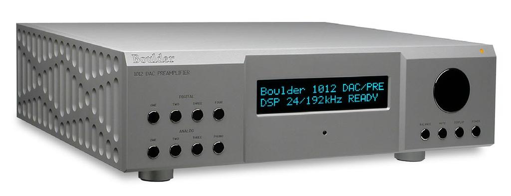
Boulder 1012 DAC Preamplifier
|
|
|
- Austen Goodman
- 5 years ago
- Views:
Transcription
1
2 Boulder 1012 DAC Preamplifier Owners Manual 10/27/03 Boulder Amplifiers, Inc Prairie Ave. Boulder, CO APPENDIX RECORDING BOULDER LINK PROGRAMMING REMOTE CONTROL OPERATION GETTING STARTED

3 B o u l d e r D A C P r e a m p l i f i e r R e a r P a n e l
4 TABLE OF CONTENTS GETTING STARTED Introduction Quick Start Placement of the 1012 DAC Preamplifier Connecting to the Mains Outlet Connecting a Digital Source Polarity Connecting a Balanced Analog Source Connecting an Unbalanced Analog Source Connecting a Turntable Connecting to a Balanced Input Amplifier Connecting to an Unbalanced Input Amplifier Setting the Boulderlink Switch OPERATION Powering Up Input Selections Volume Balance Mute Display APPENDIX RECORDING BOULDER LINK PROGRAMMING REMOTE CONTROL OPERATION GETTING STARTED
5 REMOTE CONTROL Batteries Source Selection Volume, Balance and Mute Polarity PROGRAMMING Input Names Input Polarity Theater Mode Input Level Calibration Input Balance Calibration Main Outputs Polarity Boulderlink ID Remote ID Master Reset BOULDERLINK Connecting the Boulderlink Setting Boulderlink Switches Setting Boulderlink ID Numbers Power up via Boulderlink Boulderlink Messages APPENDIX RECORDING BOULDER LINK PROGRAMMING REMOTE CONTROL OPERATION GETTING STARTED
6 RECORDING Connecting a Recording Device APPENDIX Block Diagram Specifications Troubleshooting Notes APPENDIX RECORDING BOULDER LINK PROGRAMMING REMOTE CONTROL OPERATION GETTING STARTED

7 G E T T I N G S TA RT E D INTRODUCTION Congratulations on your selection of the Boulder 1012 DAC Preamplifier. We at Boulder Amplifiers are certain it will provide years of listening pleasure. 1-1 QUICK START To get started listening, you only need to connect the 1012 as you would any other preamplifier, but you should take note of the following. WARNING: The polished volume control is attractive and because it is optical and has no stops, it is really tempting to just spin it around. DO THIS ONLY WITH THE POWER OFF! It must be given the respect you would any other volume control with its ability to get loud very quickly. By the time you have turned it up to db with a source turned on, you should be hearing some music. If not, don t proceed any louder until you have solved the problem. See trouble shooting section. For the 1012 to work properly, the Boulderlink s MASTER/SLAVE switch should be set to MASTER. A thorough reading of this manual will definitely enhance your enjoyment of your 1012 DAC Preamplifier. GETTING STARTED
8 PLACEMENT OF THE 1012 DAC PREAMPLIFIER Your Boulder 1012 DAC Preamplifier is designed to reduce the effects that external magnetic and radio fields (RF) have on its internal circuitry. While placement is not critical, known magnetic fields should be avoided. Line of sight from the listening position is necessary for the remote control to function properly. Because the preamplifier is heavy, a solid, stable surface should be used. As it will generate some heat, there should be good air circulation around it. In particular, make certain that the power supply heat sink fins on the rear of the chassis are not blocked. You may want to have some access to the rear panels for cable changes. 1-2 GETTING STARTED


9 CONNECTING TO THE MAINS OUTLET Your 1012 DAC Preamplifier is supplied with a mains cord suitable to the location where it was purchased. A label showing the exact voltage and frequency range is located on the rear panel. Make certain that the mains voltage used is with in the specifications shown. Also listed are the fuse ratings. There are two fuse holders on the rear of the 1012 which are for each of the digital and analog power transformers. Use only specified fuses. Check with qualified service person first. 1-3 GETTING STARTED


10 CONNECTING A DIGITAL SOURCE There are four digital inputs to the DSP and D/A Converter section of the Three inputs are the AES/EBU style. Because of the balanced nature of these connections, it is the preferred method of connection and should be used whenever available. With the 1012, one DABL digital adapter is supplied and may be plugged into any one of these inputs thus converting it to RCA phono style SPDIF. Additional adapters are available if more than one input needs conversion. WARNING: In order to maintain proper impedance and level matching, it is important to always use the DABL adapter when coming from an unbalanced RCA phono style digital source. Do not use a Boulder ABL analog adapter for this purpose. The fourth connector normally supplied is toslink optical. For possible future connections, consult your Boulder dealer. 1-4 GETTING STARTED
11 POLARITY Please note that the 1012 DAC Preamplifier conforms to the standard of pin 2 as the high or hot pin for all analog balanced inputs and outputs. Because input and output polarities are handled through programming setups and the remote control, no concern for polarity is needed while connecting sources. Digital connectors have no polarity. CONNECTING A BALANCED ANALOG SOURCE To fully realize the sonic potential of your 1012 DAC Preamplifier, use balanced connections whenever possible. Balanced cables reduce interference from magnetic and RF sources to an absolute minimum. Connect each line source to one of the three inputs provided. Later, you will be able to name each input with the source s name, so you might want to make a list as you connect them. 1-5 GETTING STARTED

12 CONNECTING AN UNBALANCED ANALOG SOURCE Although the inputs are all of the 3 pin type, an unbalanced source is easily accommodated by using a special cable. This cable has an RCA phono type connector on the source end and a 3 pin connector for going to an input on the 1012 DAC Preamplifier. The minus input (pin 3) should be wired to ground only at the RCA phono connector. This brings the minus input reference of the 1012 to the unbalanced source ground, thus reducing ground loops. Another option for accommodating unbalanced sources is that of the Boulder ABL analog input adapter. It converts a balanced input into a RCA phono input right at the rear of the Like the above cable, the minus input of the 1012 is connected to the ground of the RCA phono. However, this minus side will then share the shield wire with the chassis ground and will not have the best hum rejection. UNBALANCED INPUT CABLE 2-POS INPUT 3-NEG INPUT 1-GROUND 1-6 GETTING STARTED
 to either pin 2 or 3 at any point in the cable, turntable chassis, or tonearm. Pins 2 and 3 must only connect directly to the cartridge pins.")
13 CONNECTING A TURNTABLE Balanced inputs are provided for connecting a turntable to the To avoid hum pickup in the cabling, it is important to follow these instructions. Do not connect pin 1 (chassis/ground) to either pin 2 or 3 at any point in the cable, turntable chassis, or tonearm. Pins 2 and 3 must only connect directly to the cartridge pins. This can be accomplished by several wiring schemes shown on the next page. Do not use the Boulder ABL input adapter or other RCA Phono to XLR adapter. Use either a connection from pin 1 to the turntable chassis or wire from the CHASSIS screw terminal to the turntable chassis, but do not use both. For high level, moving magnet (MM) type cartridges, set the LEVEL switch to HIGH. For low level, moving coil (MC) type cartridges, set the LEVEL switch to LOW. If in doubt, consult your Boulder dealer. 1-7 GETTING STARTED
14 PHONO CABLES CARTRIDGE TURNTABLE CHASSIS 1012 PHONO INPUT 2-POS INPUT 3-POS INPUT 1-POS INPUT CHASSIS CARTRIDGE TURNTABLE CHASSIS N.C PHONO INPUT 2-POS INPUT 3-POS INPUT 1-POS INPUT CHASSIS CARTRIDGE TURNTABLE CHASSIS 1012 PHONO INPUT 2-POS INPUT 3-POS INPUT 1-POS INPUT CHASSIS 1-8 GETTING STARTED
15 CONNECTING TO A BALANCED INPUT AMPLIFIER With your 1012 DAC Preamplifier s balanced output driving a balanced input power amplifier, you can take sonic advantage of short speaker cables and correspondingly longer input cables. With the 1012 s low output impedance, distances of more than 50 meters between preamplifier and power amplifier are practical. Connect each amplifier input to the main outputs labeled MAIN OUT. If it is desired to use 2 or more amplifiers such as in bi-amping, splitters will be required. If in doubt, consult your Boulder dealer. 1-9 GETTING STARTED
16 CONNECTING TO AN UNBALANCED INPUT AMPLIFIER A special cable is required to make this connection. This cable connects pin 1 to the shield and pin 2 to the center pin. It leaves the output pin 3 unconnected. Connecting the unused output pin (usually pin 3) to ground will cause excessive ground currents and degrade performance. Use an ohmmeter or continuity checker to determine how a cable is wired. UNBALANCED OUTPUT CABLE 2-POS OUTPUT 3-NEG OUTPUT 1-GROUND LINE PREAMP INPUT 1-10 GETTING STARTED

17 SETTING THE BOULDERLINK SWITCH Set the Boulderlink MASTER / SLAVE switch to MASTER. For more information on Boulderlink, see the Boulderlink section as indicated by the finger tabs below GETTING STARTED


18 OPERATION POWERING UP With all your connections made, you are ready to listen to your Boulder 1012 DAC Preamplifier. The power LED will cycle through a variety of colors indicating a standby mode. Power is applied only to the microprocessor during this mode. Press the POWER button to turn on the The indicator will change to amber and power will be applied to the analog audio section. If a digital input was previously selected, power will also be applied to the DSP, D/A Converter, and analog low-pass filter sections which are used only for digital signals. During the power up sequence, the displays at left will be briefly shown. The front panel POWER button should be used for everyday turn on and off. This switch mutes the audio, turns off all sections except the microprocessor, and puts the preamplifier in a standby mode. 2-1 OPERATION

19 INPUT SELECTIONS To select an analog input, press one of the ANALOG pushbuttons labeled ONE, TWO, THREE or PHONO. The respective input will be shown in the display and that signal will be routed to both the main and record outputs. For example, if input ONE is chosen, A1. ANALOG INPUT 1 will show in the display. NOTE: There will be a 1 second delay when switching from one source to another. This is necessary to allow the circuitry to adjust to the new input source. 2-2 OPERATION


20 To select a digital input, press one of the DIGITAL pushbuttons labeled ONE through FOUR. For a few seconds, the input sample rate of the source and the Upandoversampling rate out of the DSP will be shown. For example, a regular CD will show INPUT RATE 44.1kHz, OUTPUT RATE 705.6kHz. The INPUT RATE is the rate at which the 1012 receives data from the source. The OUTPUT RATE is the rate at which the 1012 s Digital Signal Processor (DSP) sends data to the converters. The ratio of these two numbers is the amount of Upandoversampling performed by the DSP. Then the respective input will be shown in the display and that signal will be routed to both the main and record outputs. For example, if input ONE is chosen, D1. DIGITAL INPUT 1 will show in the display. 2-3 OPERATION


21 VOLUME Because the precise feel of the Boulder 1012 s volume control may be different than you are used to, we recommend starting the source device so that an audio signal is fed to the 1012 before increasing the volume. The display will show VOLUME INFINITE to indicate maximum attenuation or no sound. By placing a finger at the edge of the rotating control and moving it slowly so it turns in a clockwise direction, the volume will increase and an indication such as VOLUME dB in the display will show the respective volume. At this point you should be listening to music. Each volume step is a change of 0.5 db. WARNING: The volume control must be given the respect you would any other volume control with its ability to get loud very quickly. WARNING: If the input is programmed to be in THEATER MODE, then the volume control will have no effect. For more information, see THEATER MODE in the programming section. 2-4 OPERATION


22 BALANCE To change the level balance, press the BALANCE pushbutton. BALANCE CENTERED will show in the display. Now, rotating the control will change the balance instead of the volume for as long as BALANCE... is displayed. Turning the control counterclockwise (left) will cause an indication such as BALANCE R -2.0dB < in the display. This means that the right channel has been attenuated -2.0 db below the left channel, regardless of volume setting, making the left channel louder. The range of balance offset is limited to db. If the control is then rotated further counterclockwise, the BALANCE RIGHT MUTED< will be displayed to indicate that only the left channel is on. After several seconds of not changing the balance, the display will return to the VOLUME... indication. You may also return to controlling volume by again pressing the BALANCE pushbutton. The balance resolution is the same as for the volume control, 0.5 db steps. WARNING: If the input is programmed to be in THEATER MODE, then the balance control will have no effect. For more information, see THEATER MODE in the programming section. 2-5 OPERATION
23 MUTE To temporarily reduce the volume, press the MUTE pushbutton. VOLUME MUTED will show in the display, replacing the volume indication. Again pressing the MUTE pushbutton will return the volume to normal level. While muted, the level of both channels will be reduced by -100 db, regardless of volume setting. 2-6 OPERATION

24 DISPLAY The display brightness may be set to any of 4 brightness levels. To change the brightness level, press the DISPLAY pushbutton. DISPLAY 100% will show in the display. Rotate the control until the desired brightness is obtained such as DISPLAY 50%. The number in the display is the relative brightness. After several seconds of not changing the brightness level, the display will return to the VOLUME... indication. You may also return to controlling volume by again pressing the DISPLAY pushbutton. With the display at a brightness less than that of 100%, any operation of a pushbutton or the volume control will cause the display to go to full brightness for several seconds, and then return to the desired brightness. This ensures that if a function is changed, it will be noticed whether intentional or inadvertent. 2-7 OPERATION


25 R E M O T E C O N T R O L BATTERIES A standard small flat blade screwdriver is required to install the three AAA batteries. To install batteries in the remote control, it is necessary to separate the two sections. WARNING: When opened, the pushbutton balls will be loose and care must be taken to properly retain them. It is recommended to lay the remote control face down on a flat surface so that the balls will stay in position. Then, remove the three screws. Lift off the cover and set aside, making certain that the battery holder comes out from the cover. Install the batteries with the positive (+) terminals facing as indicated on the holder and replace the cover. 3-1 REMOTE CONTROL

26 SOURCE SELECTION To select an input (source) press one of the eight buttons on the left side of the remote control in the ANALOG and DIGITAL groups. You will now be listening to your desired source, and it will be showing in the display. VOLUME, BALANCE and MUTE To increase the volume, press the button marked with an up arrow. To reduce, press the one marked with a down arrow. Holding either button down will cause the volume to change continuously until released. To change the balance to the left, press the button marked with a left arrow until the display shows BALANCE CENTERED and continue holding until the display shows the desired balance change. Similarly, you may change the balance to the right by holding the button marked with a right arrow. To temporarily mute the audio, press MUTE. To return to normal audio level, again press MUTE. 3-2 REMOTE CONTROL
27 POLARITY NOTE: Often polarity is mistakenly called phase. As phase indicates any angle between two channels from 0 to 360 degrees, the correct term of polarity is preferred to indicate the 180º phase change, or inversion, available in the 1012 DAC Preamplifier. By using the remote control, the polarity of both channels may be changed simultaneously at the main outputs during any listening mode. The record outputs are never affected by the polarity setting. To change polarity, press the POL pushbutton on the remote control. POLARITY INVERTED will show in the display. Also, the decimal point after the source abbreviation (e.g. D1) will change to a - symbol for as long as the polarity remains inverted, even if the source is changed. To return to normal (noninverted) polarity, again press the POL pushbutton. POLARITY NORMAL will show in the display. 3-3 REMOTE CONTROL


28 P R O G R A M M I N G While it is not necessary to ever use any programming functions, you will find they maximize the enjoyment of your Boulder 1012 DAC Preamplifier. Each input has several programmable features associated with it. These include assigning an alphanumeric name of your choosing, setting an individual offset attenuation and balance, correcting polarity, and setting theater mode. After holding down an input button until RELEASE BUTTON NOW is displayed, each additional press of this input button will step through the programming options. Changes made during the programming process are automatically stored as they are made. If no changes are made, the original settings are retained. INPUT NAMES For the analog inputs, press and hold the input number you wish to program. If you selected ONE, then PROG ANALOG INPUT 1 will show in the top display row and CHANGE NAME? NO will show in the bottom display row. Rotating the volume control clockwise will allow you to choose YES if you want to change the name. Again press the same input source number to continue. 4-1 PROGRAMMING

29 If you chose to assign a name, then A1 ANALOG INPUT 1 will be shown in the bottom display row with a blinking cursor before the name s first character. Rotate the control until the desired character appears. Press the same input source number to accept the displayed character and go to the next character. Continue in this manner until all 17 characters are set. For example, Boulder can be set. NOTE: The space character is just before the exclamation mark (!). INPUT POLARITY Input polarity is used to match the 1012 s input polarity to that of each individual source. If uncertain of a particular source s polarity, check the source s owners manual or consult with its manufacturer. After the last character is assigned, pressing the same input source number will make INPUT PIN 2 POSITIVE show in the bottom display row. As you rotate the volume control to INPUT PIN 3 POSITIVE the polarity relays will immediately activate. After the desired polarity is selected, or if no change is desired, press the same input source number. 4-2 PROGRAMMING
30 THEATER MODE When the 1012 preamplifier is used in a surround sound theater system, it is normally desired to bypass the volume control, thus letting the surround processor control the volume. WARNING: Setting an input to THEATER MODE forces the volume to unity gain. Use only in conjunction with a surround processor. Again pressing the same input source number will make NORMAL MODE show in the bottom display row. Rotating the volume control will show THEATER MODE-Caution. 4-3 PROGRAMMING
31 INPUT LEVEL CALIBRATION Pressing the same input source number will make INPUT LEVEL 0.0dB show in the bottom display row. Rotating the volume control will change the display and the main outputs levels simultaneously. This allows calibration of each input with test tones if desired. For example, setting the display to -6.0dB will allow an input which is twice the voltage of the other inputs to be heard at the same level. A maximum of -24 db may be set. This is easiest to do if you start with the quietest source as your reference, and then adjust the louder sources to match it. 4-4 PROGRAMMING
32 INPUT BALANCE CALIBRATION Pressing the same input source number will make INPUT BAL CENTERED show in the bottom display row. Rotating the volume control will simultaneously change the display and the main output s balance so that the action can be monitored or measured. For example, setting the display to R -9.0dB will make the left channel louder than the right channel. A maximum of -12 db may be set. Again pressing the same input source number will end the programming of this input and initiate a power up sequence. 4-5 PROGRAMMING

33 PROGRAMMING BY THE DISPLAY BUTTON Several special features are programmed by pressing and holding the DISPLAY pushbutton until the display changes indicating you are in a programming mode. If no action is taken for some time, then the 1012 reverts back to normal operation. The sequence is as follows. MAIN OUTPUTS POLARITY The polarity of the main outputs may be adjusted to match the power amplifiers used. For Boulder series 1000 or 2000 amplifiers, it should be set to PIN 2 POSITIVE. If you are using a Boulder 100, 250 or 500 series, this should be set to PIN 3 POSITIVE. For other brands, consult the product s owners manual. If uncertain, set to PIN 2 POSITIVE. Press and hold the DISPLAY pushbutton. OUTPUT POLARITY, PIN 2 POSITIVE will show in the display. Rotate the volume control until the desired polarity is shown in the display. The polarity changes simultaneously with the display. 4-6 PROGRAMMING


34 BOULDERLINK ID Again pressing the DISPLAY pushbutton will make PROGRAM BOULDER LINK, BOULDER LINK ID 20 show in the display. Rotating the volume control changes the ID number. For more information consult the Boulderlink section. Unless you are using two or more 1012 DAC Preamplifiers together, this setting should be left at 20. REMOTE ID Again pressing the DISPLAY pushbutton will make PROGRAM REMOTE ID, REMOTE CONTROL ID 3 show in the display. Rotating the volume control changes the ID number. This feature is used in conjunction with a wiring change in the remote control and should be left set at 3. Consult your dealer to change this setting. BOULDERLINK SPEED Again pressing the DISPLAY pushbutton will make BOULDER LINK SPEED, BAUD-Standard show in the display. Rotating the volume control changes the baud rate. This feature increases the 1012 s compatibility with other brands of equipment. Consult your dealer to change this setting. 4-7 PROGRAMMING


35 RESET TO FACTORY DEFAULTS Should you wish to have all settings reset to original factory defaults, you may execute a master reset. Normally, this function is not used. Press and hold the POWER pushbutton. RESET ALL PARAMETERS, DIG 1=YES DIG 2=NO will show in the display. To leave all settings as they currently are, press the DIGITAL TWO pushbutton. To reset all settings, press the DIGITAL ONE pushbutton. WARNING: All settings which you have programmed in will be lost, including the names of each input. The microprocessor and PROM version numbers are momentarily displayed. All other pushbuttons are inoperative during this time. The 1012 DAC Preamplifier will then return to normal operating mode and initiate a power up sequence. 4-8 PROGRAMMING

36 BOULDER PRE- AMPLIFIER BOULDERLINK "DAISY CHAIN" BOULDER POWER AMPLIFIER BOULDER POWER AMPLIFIER MASTER SLAVE SLAVE TO ALL OTHER SLAVE UNITS B O U L D E R L I N K Boulderlink is a means of interconnecting most Boulder products so that their microprocessors can talk to each other and pass important information. Among the key features, Boulderlink allows sequential initiation of power amplifiers and other products power up when the 1012 DAC Preamplifier is turned on. Power amplifiers can send messages to the 1012 which are then shown on its display. CONNECTING THE BOULDERLINK Turn off all products to be linked before connecting Boulderlink cables and setting Boulderlink ID and Master/Slave switches. Boulderlink cables in various lengths are available as an accessory from your Boulder dealer. Two connectors are provided on the back of the 1012 and other Boulderlink enabled products. All the chassis are connected together in a daisy chain manner. Start by connecting one chassis to another then from that chassis to the next until all are connected. The order does not matter. A special interface may be obtained to enable Boulderlink to be used with other control systems. Contact your Boulder dealer for details. 5-1 BOULDER LINK


37 SETTING BOULDERLINK SWITCHES Every Boulderlink system must have one MASTER component, and only one component can be set to MASTER. Usually this is the preamplifier. Power amplifiers and other products not having a MASTER/SLAVE switch are not eligible to be MASTER. On the 1012, set the Boulderlink toggle switch to MASTER. SETTING BOULDERLINK ID NUMBERS Each component is required to have a unique Boulderlink ID number. The 1012 ID is preset to 20 at the factory and/or when a master reset sequence is executed. If multiple preamplifiers are connected together, see pages 4-5 through 4-6 for instructions on how to change the ID numbers of the additional units. Each Boulder 1000 and 2000 power amplifier has a thumbwheel switch on the rear panel. Start by setting the first switch to 0 or 1 and then going up from there without any duplication. Use of the lowest numbers will speed up turn on as each amplifier is allowed about 3 seconds before the next. This spreads out the power line inrush currents thus preventing house circuit breakers from unnecessary tripping. Up to 16 power amplifiers may be connected together in one Boulderlink cable daisy chain. 5-2 BOULDER LINK


38 POWER UP VIA BOULDERLINK With each component connected together with a Boulderlink cable, and individually connected to the mains, pressing the 1012 s POWER pushbutton will initiate the turn on sequence of all components. The first time a MASTER 1012 is powered up, it will search for any slave units connected to it. As the Master finds each slave, the slave s ID number will be shown on the display. If any of the connected slaves are amplifiers, then each time the master is turned on it will display WAITING FOR AMPS. Each amplifier will be turned on in the order of their Boulderlink ID. To minimize turn on time, the amplifier s Boulderlink IDs should be set to the lowest sequential numbers possible. For example, use 0, 1, and 2 instead of 13, 14, and 15. An amplifier set to ID 15 will take 47 seconds to turn on. A 1012 set to SLAVE, will display THIS UNIT SLAVE #20. If there is no component set to MASTER, the 1012 will display THERE IS NO MASTER! In this case, the 1012 s MASTER/SLAVE switch should be set to MASTER. It may take up to 30 seconds for the 1012 to recognize the switch change. 5-3 BOULDER LINK

39 BOULDERLINK MESSAGES Each component in the system can send a message to the 1012 which is then shown on its display. This is particularly helpful in confirming the operating status of each power amplifier in a multiple amplifier system. AMPLIFIER 1 ERROR means that an internal power supply has failed and the amplifier has turned itself off to protect the speakers from damage. AMPLIFIER 1 HAS DC means that it has turned itself off due to a DC offset voltage being detected at its inputs. AMPLIFIER 1 IS HOT means that is has turned itself off due to a higher than normal temperature condition on the heatsinks. AMPLIFIER CLIP means that the amplifier s output has momentarily reached its voltage limitation. 5-4 BOULDER LINK

40 UNIT 1 IS OFFLINE means that the slave is no longer responding via Boulderlink. Its Boulderlink cable may have become disconnected, or the mains power has been disconnected. UNIT 1 IS ONLINE means that the slave is now responding via Boulderlink in a normal manner and has been recognized by the master. 5-5 BOULDER LINK

41 RECORDING A separated analog output is provided for making recordings or supplying a fixed level output to other system components. CONNECTING A RECORDING DEVICE A recording device may be connected to the 1012 DAC Preamplifier. You may use balanced or unbalanced connections as previously described in the sections on connecting power amplifiers. See pages 1-8 and RECORDING
42 1012 AUDIO BLOCK DIAGRAM DIGITAL INPUTS DIGITAL AUDIO RECEIVER MODULE BOULDER CUSTOM DSP DIGITAL LOW PASS D/A CONVERTER 6 POLE BESSEL ANALOG LOW PASS ANALOG INPUTS K OHM BALANCED INPUT BUFFER 200 STEP ATTENUATOR BALANCED OUTPUT BUFFER MAIN OUTPUT BALANCED OUTPUT BUFFER RECORD OUTPUT PHONO 30 DB GAIN LOW NOISE RIAA CURVE PHONO STAGE 10/30 DB SWITCHABLE GAIN BUFFER 7-1 APPENDIX
43 BOULDER 1012 DAC PREAMPLIFIER SPECIFICATIONS DIGITAL INPUTS Digital Inputs 3 AES/EBU, Adapts to SPDIF (1 DABL Adapter included), 1 Toslink Sampling Rates 32, 44.1, 48, 88.2, 96 khz, (AES/EBU) Maximum DSP Sample Rate for Future I/F 192 khz Digital Signal Processor Speed 1 GFLOPS, 167 MHz Clock Decoding System 64 Bit Math, 24 Bit Output Upandoversampling 32, 44.1, 48, khz: 16X, 88.2, 96 khz: 8X Converters per Channel 2 Analog Anti-imaging Filter 3 Stage, 6 Pole Bessel Full Scale Output Level at Record Output 4.25 Vrms THD+N, 0 dbfs, 20 Hz to 1 khz % (-96.5 db) THD+N, 0 dbfs, 20 khz % (-82.5 db) S/N Ratio, A wtd. 109 db S/N Ratio, Unweighted 107 db Frequency Response, 0.03 Hz to 20 khz +0.00, -0.5 db ANALOG INPUTS Balance Line Inputs 3 Phono Inputs, Balanced Connector 1 Main Balanced Outputs 1 Record Balanced Outputs APPENDIX
44 BOULDER 1012 DAC PREAMPLIFIER SPECIFICATIONS (CTD) Maximum Input Level 6.0 Vrms Maximum Output Level 14.0 Vrms THD+N, 2V Output, from 20 Hz to 20 khz % (-96.5 db) Output loaded with 150Ω Less than 1 db distortion change, khz Maximum Voltage Gain, Line input 20 db Maximum Voltage Gain, Phono (MM) 60 db Maximum Voltage Gain, Phono (MC) 80 db Volume Range 100 db Volume Steps 0.5 db db Record Path Gain, Balanced Output 8.5 db Record Path Gain, Unbalanced Output 2.5 db Frequency Response, 20 Hz to 20 khz +0.00, db Frequency Response, -3 db at 0.02 Hz & 250 khz Clip to noise ratio 118 db Crosstalk, L to R or R to L -101 db or better 20 Hz to 20kHz Crosstalk, Adjacent Inputs -115 db or better 20 Hz to 20kHz Input Impedance 100kΩ Balanced Output Impedance 100Ω Balanced, 50Ω Unbalanced Preamp Size, W x H x D 18.0 x x inches Power Requirements 100 / 120 / V, Hz, 75 W Max. 7-3 APPENDIX
45 TROUBLESHOOTING SYMPTOM CAUSE REMEDY No power indication Preamplifier is not plugged in Connect to an AC outlet Analog source selected, Amber power indication but sound not heard from either channel Amber power indication, but sound not heard from one channel Digital source is selected, but no input signal is displayed Displays UNIT x ONLINE, then UNIT x OFFLINE continuously No signal from source No signal to power amplifier Preamp is defective No signal from one channel of source One Channel is muted by balance control D/A Converter is not receiving digital signal from source More than one slave unit has the same Boulderlink ID Check source controls, cables and connections Check amplifier power status, cables and connections Return to dealer for service Check source controls, cables and connections Push BALANCE and recenter Check controls, cables and connections from the digital source Make certain all slave units have a unique Boulderlink ID. See page APPENDIX
46 NOTES 7-5 APPENDIX
Boulder 1010 Preamplifier
 Boulder 1010 Preamplifier Owners Manual 10/1/03 Boulder Amplifiers, Inc. 3235 Prairie Ave. Boulder, CO 80301 www.boulderamp.com APPENDIX RECORDING BOULDER LINK PROGRAMMING REMOTE CONTROL OPERATION GETTING
Boulder 2020 Advance D/A Converter
 Boulder 2020 Advance D/A Converter Owners Manual V1.2 8/1/98 TABLE OF CONTENTS GETTING STARTED Placement of your 2020 D/A Converter........................................1-1 Connecting the Power Supply
508 Phono Preamplifier. Boulder Amplifiers, Inc. 255 S. Taylor Ave. Louisville, CO (303) /1/2018 Rev. 1.
 /1/2018 Rev. 1.") 508 Phono Preamplifier 6/1/2018 Rev. 1.0 P/N: 91053 Boulder Amplifiers, Inc. 255 S. Taylor Ave. Louisville, CO 80027 (303) 449-8220 www.boulderamp.com About About Boulder Amplifiers, Inc. Boulder was founded
508 Phono Preamplifier 6/1/2018 Rev. 1.0 P/N: 91053 Boulder Amplifiers, Inc. 255 S. Taylor Ave. Louisville, CO 80027 (303) 449-8220 www.boulderamp.com About About Boulder Amplifiers, Inc. Boulder was founded
RoHS. Atma-Sphere Music Preamplifier. model P-2 OWNER'S MANUAL. Please study this document carefully before using equipment
 1742 Selby Av. St. Paul, MN 55104 651 690 2246 atma sphere.com Atma-Sphere Music Preamplifier model P-2 OWNER'S MANUAL Please study this document carefully before using equipment RoHS CONGRATULATIONS!
CONSONANCE PREAMPLIFIER OWNER S MANUAL
 CONSONANCE PREAMPLIFIER OWNER S MANUAL TABLE OF CONTENTS Introduction Initial Inspection Features Installation Input Impedance Adjustments Preamplifier Internal View Impedance Adjustment Diagram Overall
CP1 OAD. Owner s Manual. Stereo Control Preamplifier. Ultrafidelity
 OAD Ultrafidelity CP1 Stereo Control Preamplifier Owner s Manual Contents Section Page No. Introduction........................................................................ 1 Warnings.................................................................................
COHERENCE ONE PREAMPLIFIER
 COHERENCE ONE PREAMPLIFIER OWNER S MANUAL TABLE OF CONTENTS Introduction Features Unpacking Instructions Installation Phono Cartridge Loading Basic Troubleshooting Technical Specifications Introduction
Owners Manual PERREAUX
 éloquence Phono Preamplifier Owners Manual PERREAUX 1 The éloquence phono preamplifier Designed and Manufactured in Dunedin, New Zealand Table of Contents INTRODUCTION... 3 Unpacking... 4 Fitting Instructions...
Introduction Front Panel Functions Rear Panel Functions Precautions Placement & Ventilation... 5
 Contents Introduction... 2 Front Panel Functions... 3 Rear Panel Functions... 3 Precautions... 5 Placement & Ventilation... 5 Installation & Operation... 5 Care & Maintenance... 7 Troubleshooting... 8
110LP MOON Series. Phono Preamplifier. Owner s Manual
 Phono Preamplifier Owner s Manual Owner s Manual I Table of Contents Introduction 4 Unpacking 5 Installation & Placement 5 Circuit Board Layout s 6 Internal Adjustments 7 Rear Panel Connections 8 Operating
INSTRUCTIONS FOR USE Pro-Ject Phono Box DS2 USB
 INSTRUCTIONS FOR USE Pro-Ject Phono Box DS2 USB Dear music lover, thank you for purchasing a Pro-Ject Audio phono amplifier. In order to achieve maximum performance and reliability you should study these
VPS 100 YPSILON PHONO STAGE. OWNERS MANUAL V1 01/01/2010 All rights reserved
 VPS 100 YPSILON PHONO STAGE OWNERS MANUAL V1 01/01/2010 All rights reserved INTRODUCTION Thank you for trusting YPSILON ELECTRONICS. We assure you that you have made an excellent purchase. Your phono stage
MODEL PA II-R (1995-MSRP $549.00)
") F O R T H E L O V E O F M U S I C MODEL PA II-R (1995-MSRP $549.00) OWNER'S MANUAL AND INSTALLATION GUIDE INTRODUCTION To aid in the exciting and custom installs which installers are performing all over
F O R T H E L O V E O F M U S I C MODEL PA II-R (1995-MSRP $549.00) OWNER'S MANUAL AND INSTALLATION GUIDE INTRODUCTION To aid in the exciting and custom installs which installers are performing all over
A y r e. K-1x Preamplifier. Owner s Manual
 A y r e K-1x Preamplifier Owner s Manual Table of Contents Welcome to Ayre........................... 2 Installation and Operation......................... 3 Optimizing the Phono Stage........................
OWNERS MANUAL LUNATEC V3 MICROPHONE PREAMPLIFIER AND A/D CONVERTER
 OWNERS MANUAL LUNATEC V3 MICROPHONE PREAMPLIFIER AND A/D CONVERTER LUNATEC 35 +48 35 +48 30 40 30 40 0 25 45 25 45 3 192 1 1 6 176.4 20 50 20 50 9 96 12 PEAK 88.2 55 55 RESET 48 10 60 2 10 60 2 21 44.1
GAMBIT DAC1 OPERATING MANUAL
 digital audio weiss engineering ltd. Florastrasse 42, 8610 Uster, Switzerland +41 1 940 20 06 +41 1 940 22 14 http://www.weiss.ch / http://www.weiss-highend.com GAMBIT DAC1 OPERATING MANUAL Software Version:
The performance of a lifetime. Owner s Manual MOON 110LP v2 Phono Preamplifier
 The performance of a lifetime Owner s Manual MOON 110LP v2 Phono Preamplifier MOON by Simaudio simaudio.com Simaudio Ltd 1345 Newton Road, Boucherville, Québec J4B 5H2 CANADA Date Code: 20180831 01 INTRODUCTION
ModWright Instruments, Inc. PH 150 Tube Phono Stage Owner s Manual
 ModWright Instruments, Inc. PH 150 Tube Phono Stage Owner s Manual Manufactured by ModWright Instruments, Inc. 21919 399th St., Amboy, WA 98601 USA www.modwright.com 1 CAUTIONS: Do not operate or power
INSTRUCTIONS FOR USE Pro-Ject Tube Box DS2
 INSTRUCTIONS FOR USE Pro-Ject Tube Box DS2 Dear music lover, Thank you for purchasing a tube phono preamplifier from Pro-Ject Audio Systems. In order to achieve maximum performance and reliability you
Mapletree Audio Design
 Ultra 4C Preamplifier Mapletree Audio Design Ultra 4C Stereo Phono/Line Preamplifier PS 2D Power Supply User s Manual Rev. Mar. 22, 2019 Mapletree Audio Design R. R. 1, Seeley's Bay, Ontario, Canada, K0H
USER MANUAL GOLDMUND PH3 Phono Preamplifier
 USER MANUAL GOLDMUND PH3 Phono Preamplifier Congratulations. Thank you for purchasing the Goldmund PH3 Phono Preamplifier. You have acquired the best Phono Preamplifier ever made for professional and domestic
USER MANUAL GOLDMUND MIMESIS 32.5 Universal Acoustic Processor
 USER MANUAL GOLDMUND MIMESIS 32.5 Universal Acoustic Processor Congratulations. Thank you for purchasing the Goldmund MIMESIS 32.5 UNIVERSAL ACOUSTIC PROCESSOR. You have acquired the best multi-usage acoustic
BP2-MM/MC Phono Preamplifier Owner s Manual
 BP2-MM/MC Phono Preamplifier Owner s Manual Important Safety Instructions The lightning flash with arrowhead symbol within an equilateral triangle, is intended to alert the user to the presence of un-insulated
CLASSÉ AUDIO CP-60 REMOTE CONTROL BALANCED PREAMPLIFIER CP-60 OWNER'S MANUAL
 CLASSÉ AUDIO CP-60 REMOTE CONTROL BALANCED PREAMPLIFIER CP-60 OWNER'S MANUAL CLASSÉ DESIGN PHILOSOPHY 1. REPEATED LISTENING DESIGN SESSIONS: Fine tuning of sound by exchanging and mixing of parts (transistors,
Hegel HD20 High End D/A Converter
 Hegel HD20 High End D/A Converter www.hegel.com info@hegel.com USER GUIDE Congratulations on your new HEGEL! Every Hegel product is based on a simple philosophy: The audio reproduction instrument shall
PREAMPLIFIER INTRODUCTION INSTRUCTIONS FOR USE. Thank you for purchasing the Musical Fidelity A3 CR remote control preamplifier.
 INTRODUCTION A3 CR PREAMPLIFIER INSTRUCTIONS FOR USE Thank you for purchasing the Musical Fidelity A3 CR remote control preamplifier. Used properly and carefully, it should give you many years of outstanding
INSTRUCTIONS FOR USE Pro-Ject Tube Box DS2
 INSTRUCTIONS FOR USE Pro-Ject Tube Box DS2 Dear music lover, Thank you for purchasing this tube phono preamplifier from Pro-Ject Audio Systems. In order to achieve maximum performance and reliability you
ORPHEUS ZERO U S E R M A N U A L
 ORPHEUS ZERO U S E R M A N U A L I N T R O D U C T I O N FEATURES Class 1 product CD drive (ORPHEUS ZERO Drive) or player (ORPHEUS ZERO Player) Multiple formats reader : CD, CD-R, CD-RW Software controlled
INSTRUCTIONS FOR USE Pro-Ject Tube Box DS2
 INSTRUCTIONS FOR USE Pro-Ject Tube Box DS2 Dear music lover, Thank you for purchasing a tube phono preamplifier from Pro-Ject Audio Systems. In order to achieve maximum performance and reliability you
Owner's Manual PPA-1 Phono Preamp
 Owner's Manual PPA-1 Phono Preamp Contents Legal Notifications 2 Warranty Information 2 Installation and Usage Tips 3 Connections and Controls 3 Front panel Rear panel Connecting the PPA-1 to Your System
Professional Fidelity Mastering Grade Listening
 Professional Fidelity Mastering Grade Listening Director ON SOURCE VOLUME VOLTAiR 120V DC Audio Rail DAC Preamplifier This User Manual is optimized for Acrobat Reader. Interactive buttons may not appear
Low Noise Solid State Phono Preamplifier User's Guide and Operating Information
 Bel Canto Design PHONO 1 Low Noise Solid State Phono Preamplifier User's Guide and Operating Information Bel Canto Design 212 Third Avenue North Suite 345 Minneapolis, MN 55401 Phone: (612) 317.4550 Fax:
USB Phono Plus. Project Series USER S MANUAL. Audiophile Computer Interface
 USB Phono Plus Audiophile Computer Interface Project Series USER S MANUAL IMPORTANT SAFETY INSTRUCTION READ FIRST This symbol, whenever it appears, alerts you to the presence of uninsulated dangerous voltage
Operating Manual. Mark Levinson Nº25 Dual Monaural Phono Preamplifier. Madrigal Audio Laboratories, Inc. 1
 Operating Manual Mark Levinson Nº25 Dual Monaural Phono Preamplifier Madrigal Audio Laboratories, Inc. 1 WARNING: TO REDUCE THE RISK OF FIRE OR ELECTRIC SHOCK, DO NOT EXPOSE THIS APPLIANCE TO RAIN OR MOISTURE.
DP1 DYNAMIC PROCESSOR MODULE OPERATING INSTRUCTIONS
 DP1 DYNAMIC PROCESSOR MODULE OPERATING INSTRUCTIONS and trouble-shooting guide LECTROSONICS, INC. Rio Rancho, NM INTRODUCTION The DP1 Dynamic Processor Module provides complete dynamic control of signals
DIGITAL SPEAKER MANAGEMENT UK
 DSM2-6mkII DIGITAL SPEAKER MANAGEMENT 170.659UK Features 96kHz sampling frequency, 32-bit A/D and D/A converter, 24-bit DSP processor Input channel: 6-band parametric EQ, Delay, Polarity Output channel:
SATRI AMPLIFIER AMP-51R. Owner s Manual
 SATRI AMPLIFIER AMP-51R Owner s Manual contents SAFETY INSTRUCTIONS 4 INTRODUCTION 6 OVERVIEW (FRONT PANEL) 8 OVERVIEW (REAR PANEL) 9 OVERVIEW (REMOTE CONTROL) 1 1 OPERATION 12 TROUBLESHOOTING 13 SPECIFICATION
Element 78 MPE-200. by Summit Audio. Guide To Operations. for software version 1.23
 Element 78 MPE-200 by Summit Audio Guide To Operations for software version 1.23 TABLE OF CONTENTS IMPORTANT SAFETY AND GROUNDING INSTRUCTIONS COVER 1. UNPACKING AND CONNECTING...3 AUDIO CONNECTIONS...4
PH60B Phono Stage. User Guide
 PH60B Phono Stage User Guide is a division of Radial Engineering Ltd. 1588 Kebet Way, Port Coquitlam BC, Canada V3C 5M5 (604) 942-1001 info@hafler.com www.hafler.com PH60B Phono stage USER GUIDE Table
USER MANUAL Goldmund PH3.8 Phono Preamplifier
 USER MANUAL Goldmund PH3.8 Phono Preamplifier Congratulations. Thank you for purchasing the Goldmund PH3.8 Phono Preamplifier. You have acquired the best Phono Preamplifier ever made for professional and
+41 * 2 db. GENERAL The Shure M675 Broadcast Production Master is designed for use in conjunction with a Shure M67 or
 2 2 2 HARTREY AVE., EVANSTON, IL. 6 0 2 0 4 U.S.A. GENERAL The Shure M675 Broadcast Production Master is designed for use in conjunction with a Shure M67 or M67-2E Professional Microphone Mixer, M63 Audio
Table of Contents. Read This First.2. Introduction by Jim Fosgate...3. Unpacking..4. Tubes and Tube shield Installation 5. Product Placement...
 Owner s Manual Table of Contents Read This First.2 Introduction by Jim Fosgate...3 Unpacking..4 Tubes and Tube shield Installation 5 Product Placement...6 Connecting your Fosgate Signature..7 Phono stage
LavryBlack Series Model DA10 Digital to Analog Converter
 LavryBlack Series Model DA10 Digital to Analog Converter Lavry Engineering, Inc. P.O. Box 4602 Rolling Bay, WA 98061 http://lavryengineering.com email: techsupport@lavryengineering.com January 14, 2008
music hall pa2.2 INSTRUCTION MANUAL music hall
 music hall pa2.2 INSTRUCTION MANUAL music hall http://www.musichallaudio.com CONGRATULATIONS ON YOUR PURCHASE You have selected an exceptional phono preamplifier. Each component used in the construction
Sphinx II. Owner s Manual. Tube Hybrid Integrated Power Amplifier. Rogue Audio, Inc. 3 Marian Lane Brodheadsville, PA Issue date: 08/01/16
 Sphinx II Tube Hybrid Integrated Power Amplifier Owner s Manual Rogue Audio, Inc. 3 Marian Lane Brodheadsville, PA 18322 Issue date: 08/01/16 TABLE OF CONTENTS 1) Introduction 2 2) Unpacking the Sphinx
DLM471S-5.1 MULTICHANNEL AUDIO LEVEL MASTER OPERATION MANUAL IB B. (Mounted in RMS400 Rack Mount & Power Supply) (One of 4 Typical Cards)
 (One of 4 Typical Cards)") DLM471S-5.1 (Mounted in RMS400 Rack Mount & Power Supply) MULTICHANNEL AUDIO LEVEL MASTER (One of 4 Typical Cards) OPERATION MANUAL IB6432-02B TABLE OF CONTENTS PAGE 1.0 GENERAL DESCRIPTION 2 2.0 INSTALLATION
DLM471S-5.1 (Mounted in RMS400 Rack Mount & Power Supply) MULTICHANNEL AUDIO LEVEL MASTER (One of 4 Typical Cards) OPERATION MANUAL IB6432-02B TABLE OF CONTENTS PAGE 1.0 GENERAL DESCRIPTION 2 2.0 INSTALLATION
BP2-MM MM Phono Preamplifier Owner s Manual
 BP2-MM MM Phono Preamplifier Owner s Manual Important Safety Instructions The lightning flash with arrowhead symbol within an equilateral triangle, is intended to alert the user to the presence of un-insulated
TABLE OF CONTENTS. 1) Introduction 2. 2) Unpacking the Ares 2. 3) Installing the Ares in your system 3. 4) Setting the Operational Parameters 4
 Introduction 2. 2) Unpacking the Ares 2. 3) Installing the Ares in your system 3. 4) Setting the Operational Parameters 4") TABLE OF CONTENTS 1) Introduction 2 2) Unpacking the Ares 2 3) Installing the Ares in your system 3 4) Setting the Operational Parameters 4 5) High Output MM/MC Cartridge Setup 6 6) Medium Output Cartridge
TABLE OF CONTENTS 1) Introduction 2 2) Unpacking the Ares 2 3) Installing the Ares in your system 3 4) Setting the Operational Parameters 4 5) High Output MM/MC Cartridge Setup 6 6) Medium Output Cartridge
bel canto SEP2 Single Ended Triode Tube Preamplifier User's Guide and Operating Information
 bel canto SEP2 Single Ended Triode Tube Preamplifier User's Guide and Operating Information Bel Canto Design 212 Third Avenue North, Suite 274 Minneapolis, MN 55401 USA Phone: 612 317.4550 Fax: 612.359.9358
USER MANUAL GOLDMUND METIS 7 Integrated Amplifier
 USER MANUAL GOLDMUND METIS 7 Integrated Amplifier Congratulations. Thank you for purchasing the Goldmund METIS 7. You have acquired the best multi-usage ever made for professional and domestic uses. Please
R e c e i v e r. Receiver
 R e c e i v e r Receiver > Eight channels > Eight configurable inputs > Three independent zones > Integrated 7-channel amplifier with massive toroidal transformer and thermal/dc protection > AM/FM tuner
INSTRUCTIONS FOR USE Pro-Ject A/D Phono Box S
 INSTRUCTIONS FOR USE Pro-Ject A/D Phono Box S Dear music lover, thank you for purchasing an A/D Phono Box S from Pro-Ject Audio Systems. In order to achieve maximum performance and reliability you should
J R Sky, Inc. tel: fax:
 STEREO OPTICAL RECORDING SYSTEM N UOPTIX STEREO OPTICAL RECORDING MONITOR LEFT SYSTEM MODE PREVIEW RECORD BIAS RECORD REV SETUP TEST RIGHT INPUT SETUP INPUT BIAS SETUP BIAS INPUT STEREO AUX MONO DIRECT
4 Input A/V Switcher with Automatic Input Mode and Volume Stabilizer. Model SVS-4D. User Manual
 4 Input A/V Switcher with Automatic Input Mode and Volume Stabilizer Model SVS-4D User Manual Table of Contents WHAT S INCLUDED... 2 INTRODUCTION... 3 IMPORTANT SAFETY PRECAUTIONS... 3 FRONT PANEL... 4
Professional Power Amplifier Specifications...8 SPECIFICATION
 Contents Contents...1 Important note...2 Control elements...3 Rear panel features introduction...4 Rear panel features introduction...5 Audio input and output connections...6 PC Interface...7 Professional
T L Audio. User Manual C1 VALVE COMPRESSOR. Tony Larking Professional Sales Limited, Letchworth, England.
 T L Audio User Manual C1 VALVE COMPRESSOR Tony Larking Professional Sales Limited, Letchworth, England. Tel: 01462 490600. International +44 1462 490600. Fax: 01462 490700. International +44 1462 490700.
Owner s Manual. Model PH8 Phono Preamplifier
 Owner s Manual Model PH8 Phono Preamplifier 2 Contents Model PH8 Phono Preamplifier Illustrations 4 Preface 5 Warnings 5 Packaging 5 Front Panel Controls 5 6 Remote Control Functions 6 Connections 6 Installation
Operating Manual. Mark Levinson Nº28 Preamplifier. Madrigal Audio Laboratories, Inc. 15
 Operating Manual Mark Levinson Nº28 Preamplifier Madrigal Audio Laboratories, Inc. 15 WARNING: TO REDUCE THE RISK OF FIRE OR ELECTRIC SHOCK, DO NOT EXPOSE THIS APPLIANCE TO RAIN OR MOISTURE. CAUTION RISK
Orpheus. Phono Preamplifier. by Thrax Audio. Operating Manual. Manual issued 05/03/2012 CAUTION
 Orpheus Phono Preamplifier by Thrax Audio Operating Manual Manual issued 05/03/2012 CAUTION THE UNIT CONTAINS NO USER SERVICEABLE PARTS. DO NOT REMOVE THE COVERS. LETHAL VOLTAGES ARE PRESENT WITHIN THE
MclNTOSH MODEL C-4 and C-4P
 INSTRUCTION MANUAL MclNTOSH MODEL C-4 and C-4P AUDIO COMPENSATORS McINTOSH LABORATORY, INC. 320 Water St. Binghamton, N. Y. U.S.A. - 1 - INSTRUCTION MANUAL McINTOSH MODEL C-4 and C-4P AUDIO COMPENSATORS
Recording to Tape (Analogue or Digital)...10
...10") c o n t e n t s DUAL MIC-PRE Green Dual Mic Pre (introduction).............................4 Section (i): Setting Up Power Connections...........................................4 Power Supply................................................5
c o n t e n t s DUAL MIC-PRE Green Dual Mic Pre (introduction).............................4 Section (i): Setting Up Power Connections...........................................4 Power Supply................................................5
OPERATION NOTES FOR PSIDEX AUDIO PGP-1A PRE-AMPLIFIER DESCRIPTION INSTALLATION
 OPERATION NOTES FOR PSIDEX AUDIO PGP-1A PRE-AMPLIFIER DESCRIPTION The Psidex Audio Laboratory PGP- 1A is a vacuum tube based microphone preamp and program line amplifier designed to provide solid, robust
Model CMX3838A2 AV Matrix Switch with DSP audio (firmware 1.0)
") Model CMX3838A2 AV Matrix Switch with DSP audio (firmware 1.0) Overview: This product is a full featured video & audio matrix switch. It is most commonly used to independently distribute video & audio
Model CMX3838A2 AV Matrix Switch with DSP audio (firmware 1.0) Overview: This product is a full featured video & audio matrix switch. It is most commonly used to independently distribute video & audio
Reference 150 LINEAR
 Reference 150 LINEAR USER GUIDE Congratulations on your new CONSONANCE! Our products are based on a simple philosophy: The component shall reproduce the original musical sound, purely and naturally. The
KORU. Phono Preamplifier Instruction Manual. The heart of music
 KORU Phono Preamplifier Instruction Manual The heart of music www.pliniusaudio.com Contents Introduction...2 Design Philosophy...3 Unpacking...4 Placement & Ventilation...4 Care & Maintenance...5 Precautions...6
MANUAL ENGLISH Core Club Ordercode: D2314
 MANUAL ENGLISH Core Club Ordercode: Highlite International B.V. Vestastraat 2 6468 EX Kerkrade the Netherlands Table of contents Warning... 2 Unpacking Instructions... 2 Safety Instructions... 2 Operating
OTM FREQUENCY AGILE 750MHz F.C.C. COMPATIBLE TELEVISION MODULATOR INSTRUCTION MANUAL
 OTM-4000 FREQUENCY AGILE 750MHz F.C.C. COMPATIBLE TELEVISION MODULATOR INSTRUCTION MANUAL Phone: (209) 586-1022 (800) 545-1022 Fax: (209) 586-1026 E-Mail: salessupport@olsontech.com 025-000331 REV B www.olsontech.com
MATRIX. 24Bit /192kHz ASRC Stereo Audio Processor MATRIX. 2-Channel 24-bit 192-kHz ASRC Desktop Digital Audio Processor CUBE.
 24Bit /192kHz ASRC Stereo Audio Processor 2-Channel 24-bit 192-kHz ASRC Desktop Digital Audio Processor User Guide CUBE Thank you for purchasing digital audio processor! This manual booklet provides you
USER MANUAL. GOLDMUND MIMESIS 20.7 D/A Converter
 USER MANUAL GOLDMUND MIMESIS 20.7 D/A Converter Thank you for purchasing the Goldmund MIMESIS 20.7 D/A CONVERTER. Please take some time to read this manual. It will provide you with useful information
PROFESSIONAL 2 CHANNEL SOLID-STATE MIC / LINE PREAMPLIFIER USER S MANUAL
 PROFESSIONAL 2 CHANNEL SOLID-STATE MIC / LINE PREAMPLIFIER USER S MANUAL SAFETY INSTRUCTIONS This symbol, wherever it appears, alerts you to important operating and maintenance instructions in the accompanying
There is a button to select either the AES/EBU or S/PDIF input for the D/A converter, which is located on the rear panel.
 4 RB-DAC1 Digital to Analogue Converter Introduction Fig 4-1: RB-DAC1 Front Panel Using 24 bit, 96kHz capable devices, the RB-DAC1 Digital to Analogue Converter is a 1U rack-mount which produces a stereo
Revision 1.2d
 Specifications subject to change without notice 0 of 16 Universal Encoder Checker Universal Encoder Checker...1 Description...2 Components...2 Encoder Checker and Adapter Connections...2 Warning: High
DCX-24 ORDERCODE D2020
 DCX-24 ORDERCODE D2020 Congratulations! You have bought a great, innovative product from DAP Audio. The DAP Audio DCX-24 brings excitement to any venue. Whether you want simple plug-&-play action or a
Mercedes Benz NTG5+ MOST150 to 12-channel Analog & Digital sound processor NTV-KIT871
 3950 NW 120 th Ave, Coral Springs, FL 33065 TEL 561-955-9770 FAX 561-955-9760 Mercedes Benz NTG5+ MOST150 to 12-channel Analog & Digital sound processor NTV-KIT871 WARNING: Do not connect any RCA cables
Owner s Manual. Model REFERENCE PHONO 2 P R E A M P L I F I E R
 Owner s Manual Model REFERENCE PHONO 2 P R E A M P L I F I E R 3900 ANNAPOLIS LANE NORTH / PLYMOUTH, MINNESOTA 55447-5447 / PHONE: 763-577-9700 FAX: 763-577-0323 www.audioresearch.com Contents 1 Model
Technical Specifications
 INSTALLATION SHEET AND OPERATORS MANUAL General Description: The is a mixer/preamplifier that includes 6 channels that each include a microphone input at screw terminals and an aux input at an RCA jack.
SAWM60 AUDIO/VIDEO MODULATOR
 SAWM60 LIMITED WARRANTY Holland Electronics LLC, warrants that the product enclosed with this Limited Warranty statement will conform to the manufacturer s specifications and be free of defects in the
Kramer Electronics, Ltd. USER MANUAL. Models: VS-162AV, 16x16 Audio-Video Matrix Switcher VS-162AVRCA, 16x16 Audio-Video Matrix Switcher
 Kramer Electronics, Ltd. USER MANUAL Models: VS-162AV, 16x16 Audio-Video Matrix Switcher VS-162AVRCA, 16x16 Audio-Video Matrix Switcher Contents Contents 1 Introduction 1 2 Getting Started 1 3 Overview
Pre-Amplifier. Owner s Manual
 Pre-Amplifier Owner s Manual Thank you and congratulations on your purchase of this Yamaha product. You can enjoy the high-quality stereo sound of this preamplifier at home. This Owner s Manual describes
3124mb+ All Discrete 4 Channel Mic/Instrument Preamplifier with Stereo Mixer Operator s Manual
 3124mb+ All Discrete 4 Channel Mic/Instrument Preamplifier with Stereo Mixer Operator s Manual Written by Carl J Houde 2015 Table of Contents 1.0 Introduction... 3 2.0 Overview... 4 2.1 3124mb+ Features
PH 1.1 Phono Preamplifier Owner s Manual
 PH 1.1 Phono Preamplifier Owner s Manual Nerve Audio, Inc. 822 SW 75th Way Gainesville, FL 32607 INTRODUCTION Thank you for your purchase!! The Nerve Audio PH-1.1 represents our statement about the quality-versus-value
M2 RIAA Owner s Information
 M2 RIAA Owner s Information The M2 RIAA is a Level 2 RIAA phono stage, developed for the best possible sonic performance rather than technical specifications. To this end, the M2 RIAA incorporates thermionic
N o_ INTEGRATED AMPLIFIER
 N o_ 585.5 INTEGRATED AMPLIFIER 585.5 INTEGRATED AMPLIFIER WITH PURE PHONO STAGE Introducing the Mark Levinson 585.5 Integrated Amplifier. With unsurpassed analog performance, advanced digital audio capability
32 Channel CPCI Board User Manual
 0 Sections Page 1.0 Introduction 1 2.0 Unpacking and Inspection 1 3.0 Hardware Configuration 1 4.0 Board Installation 5 5.0 I/O Connections and the Front Panel 5 5.1 Front Panel Layout 5 5.2 Input and
MP-204D Digital/Analog Stereo Monitor Panel
 MP-204D Digital/Analog Stereo Monitor Panel Videoquip Research Limited 595 Middlefield Road, Unit #4 Scarborough, Ontario, Canada. MIV 3S2 (416) 293-1042 1-888-293-1071 www.videoquip.com 1 Videoquip MP-204D
O W N E R ' S M A N U A L. D/AC-1100 Digital/Analog Converter
 O W N E R ' S M A N U A L D/AC-1100 HD Digital to Analog Converter Congratulations on your purchase of this precision audio component and thank you for your selection of Parasound. The D/AC-1100 HD is
MASTERING DIGITAL TO ANALOG USER MANUAL. VER.7/April Use ver.5 manual for earlier units (without toslink)
") MASTERING DIGITAL TO ANALOG CONVERTER USER MANUAL VER.7/April 2007 Use ver.5 manual for earlier units (without toslink) Quick Start.3 Introduction.....4 This manual may be updated Download the newest version
MASTERING DIGITAL TO ANALOG CONVERTER USER MANUAL VER.7/April 2007 Use ver.5 manual for earlier units (without toslink) Quick Start.3 Introduction.....4 This manual may be updated Download the newest version
Dream. Prism. Operation Manual
 Prism Dream Operation Manual st Issue 2.01 21 January 1998 Prism Media Products Limited William James House Cowley Road Cambridge CB4 4WX UK Phone: +44-(0)1223-424988 Fax: +44-(0)1223-425023 Email: support@prismsound.com
VK-P10SE WARRANTY REGISTRATION FORM
 VK-P10SE WARRANTY REGISTRATION FORM Unit Serial Number: Customer Name: Address: Date of Purchase: Purchased From: Dealer Name: Address: IMPORTANT NOTE: In order to receive the full five-year product warranty,
Since Stereo Preamplifier. An introduction to the technology within the Boulder 1110 Stereo Preamplifier.
 Since 1984 1110 Stereo Preamplifier An introduction to the technology within the Boulder 1110 Stereo Preamplifier. Welcome Basic Design What constitutes a high-performance preamplifier? The feel of the
Vorne Industries. 87/719 Analog Input Module User's Manual Industrial Drive Itasca, IL (630) Telefax (630)
 Telefax (630)") Vorne Industries 87/719 Analog Input Module User's Manual 1445 Industrial Drive Itasca, IL 60143-1849 (630) 875-3600 Telefax (630) 875-3609 . 3 Chapter 1 Introduction... 1.1 Accessing Wiring Connections
Vorne Industries 87/719 Analog Input Module User's Manual 1445 Industrial Drive Itasca, IL 60143-1849 (630) 875-3600 Telefax (630) 875-3609 . 3 Chapter 1 Introduction... 1.1 Accessing Wiring Connections
INTEGRATED AMPLIFIER INSTRUCTIONS FOR USE
 INTEGRATED AMPLIFIER INSTRUCTIONS FOR USE Thank you for purchasing the Musical Fidelity Amplifier. Used properly and carefully, it should give you many years of outstanding musical reproduction. The is
ATMA-SPHERE MUSIC PREAMPLIFIER. model MP-3 Mk. 3.2 OWNER'S MANUAL
 ATMA-SPHERE MUSIC PREAMPLIFIER model MP-3 Mk. 3.2 OWNER'S MANUAL Please study this document carefully before using equipment RoHS 2012 Atma-Sphere Music Systems Inc 1742 Selby Ave. St. Paul, MN 55104 651-690-2246
RMX-44 & RMX-62 MIXING MATRIX. Installation & Operation Manual
 RMX-44 & RMX-6 MIXING MATRIX Installation & Operation Manual TABLE OF CONTENTS RMX-44 & RMX-6 INTRODUCTION... RMX-44 CALLOUTS... RMX-44 BLOCK DIAGRAM... RMX-6 CALLOUTS... 4 RMX-6 BLOCK DIAGRAM... 5 RMX-44
SA-3 OWNER S MANUAL. (954) STANTON MAGNETICS, INC PROFESSIONAL DJ MIXER
 STANTON MAGNETICS, INC PROFESSIONAL DJ MIXER") SA3_manual_FINAL 2/18/0 2:26 PM Page 1 2003, Stanton Magnetics, INC SA-3 PROFESSIONAL DJ MIXER OWNER S MANUAL STANTON MAGNETICS, INC info@stantonmagnetics.com (94) 689-8833 www.stantondj.com SA3_manual_FINAL
SA3_manual_FINAL 2/18/0 2:26 PM Page 1 2003, Stanton Magnetics, INC SA-3 PROFESSIONAL DJ MIXER OWNER S MANUAL STANTON MAGNETICS, INC info@stantonmagnetics.com (94) 689-8833 www.stantondj.com SA3_manual_FINAL
Owner s Manual PRE1. v1.2. Triode Class A Line Preamplifier
 Owner s Manual PRE1 Triode Class A Line Preamplifier www.lab12.gr v1.2 Table of Contents It is yours Features Installation & Placement Front Panel Rear Panel Remote Control Main connections For the safety
MP1100 Phono Preamplifier Owner s Manual
 McIntosh Laboratory, Inc. 2 Chambers Street Binghamton, New York MP1100 Phono Preamplifier Owner s Manual 13903-2699 Phone: 607-723-3512 www.mcintoshlabs.com Important Safety Information is supplied in
Premier. Pre-Amplifiers. User Manual
 Premier Pre-Amplifiers User Manual Models Covered Phono Stage MM Head Amplifier MC Line Pre-Amplifier + Remote Version Line / Phono MM Pre-Amplifier + Remote Version Line / Phono MM Plus + Remote Version
Instruction Manual By Digital & Analog
 FEMTO Instruction Manual By Digital & Analog www.calyxaudio.com 1 Thank you for purchasing FEMTO Music is the most important messenger of human emotion as well as a meaning of its expression since human
HMA-860H AGILE MODULATOR
 HMA-860H AGILE MODULATOR LIMITED WARRANTY Holland Electronics LLC, warrants that the product enclosed with this Limited Warranty statement will conform to the manufacturer s specifications and be free