23" UNIVERSAL MOUNT INDUSTRIAL MONITOR REVISION B USER MANUAL
|
|
|
- Cecily Miles
- 6 years ago
- Views:
Transcription


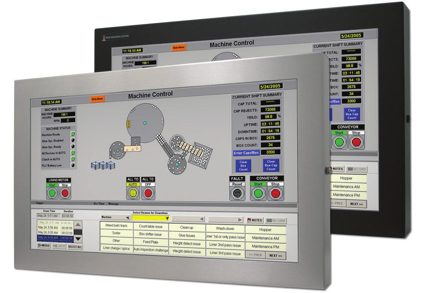

1 23" UNIVERSAL MOUNT INDUSTRIAL MONITOR REVISION B USER MANUAL Model No. HIS-UM23- _ B
2 Table of Contents Safety and Regulatory Information...3 FCC Notice...3 Hazardous Locations...4 Waste Electrical and Electronic Equipment Directive (WEEE)... 4 Mechanical Drawings...5 Front View...5 Rear View...5 Side View...6 Installation Instructions...7 Step 1: Prepare for Installation...7 Step 2: Bench-test Configuration...8 Install Cable Connections... 8 Install Touch Screen Driver... 9 Step 3: Install the Monitor Fully Assembled Workstations...11 Install Cable Exit Cover Plate...11 Mount the Monitor Video Settings...15 Setting the Timing Mode...15 Control Panel Buttons...16 OSD and Power Lock Settings...17 On-Screen Display (OSD) Menus...18 Auto Image Adjust Menu Contrast / Brightness Menu Input Select Menu Color Adjust Menu Information Menu Manual Image Adjust Menu Setup Menu Memory Recall Menu Cleaning Instructions...24 Troubleshooting...25 Video Troubleshooting...25 Touch Screen Troubleshooting...27 Specifications...28 Display...28 Environmental...28 Electrical...28 Video...29 Functional...29 Physical...30 Compliances and Certifications...30 Warranty Statement UM23B User Manual, 99149, January 2017
3 Safety and Regulatory Information Safety and Regulatory Information! WARNING! To prevent fire or shock hazard, do not expose live components to rain or moisture. Dangerously high voltages are present inside the unit. Do not disassemble the unit. Refer servicing to qualified personnel only. This equipment is not intended for use in critical applications where its failure to operate would create immediate life threatening circumstances. Applications including, but not limited to, nuclear reactor control, aerospace navigation systems and life support systems are not appropriate for this product. To be covered by UL rd Edition, the monitor covered in this report is required to be used with a Listed computer, and the socket-outlet shall be installed near the equipment and shall be easily accessible. DC Supplied Units only: The HISUM23 subject unit is to be powered by a Listed Power Supply suitable for the application with outputs at SELV/LPS or Class 2 levels rated VDC, 2.5 A max. The equipment is not intended to connect directly to a DC Mains source. FCC Notice This equipment has been tested and found to comply with the limits for a Class A digital device, pursuant to Part 15 of the FCC Rules. These limits are designed to provide reasonable protection against harmful interference when the equipment is operated in a commercial environment. This equipment generates, uses, and can radiate radio frequency energy and, if not installed and used in accordance with the instruction manual, may cause harmful interference to radio communications. Operation of this equipment in a residential area is likely to cause harmful interference in which case the user will be required to correct the interference at his own expense. Any changes or modifications not expressly approved by the grantee of this device could void the user s authority to operate the device. UM23B User Manual, 99149, January
4 Safety and Regulatory Information Hazardous Locations The following applies only to monitors rated for hazardous locations (model numbers HIS-UM23- HB and HIS-UM23- UB): This equipment is suitable for use in Class I, Division 2, Groups A, B, C, and D; Class II, Division 2, Groups F and G; Class III; or non-hazardous locations only. WARNING EXPLOSION HAZARD Do not disconnect equipment unless power has been removed or the area is known to be non-hazardous. WARNING EXPLOSION HAZARD Substitution of any components may impair suitability for Class I, II & III, Division 2 Locations. NOTE: Hope Industrial Systems provides wiring and conduit that complies with the U.S. National Electric Code but cannot rate wiring or conduit methods for hazardous locations, as these must be locally inspected and approved. The customer must install their hazardous location rated monitor in accordance with the applicable electrical codes for their location. YB, PED4X4, and FPED series are not approved for routing internal cables in Class II or III locations. If these mounting options are desired, customer must route cables outside of pedestal. Choose only CP-CON-xx or CP-BLNK-xx cover plate series for Universal Mount Monitors for hazardous locations. Waste Electrical and Electronic Equipment Directive (WEEE) The following information is only for EU-member states: The mark shown to the right is in compliance with the Waste Electrical and Electronic Equipment Directive 2002/96/EC (WEEE). The mark indicates the requirement NOT to dispose of the equipment as unsorted municipal waste, but use the return and collection systems according to local law. Users should contact their supplier and check the terms and conditions of the purchase contract. When purchased directly from Hope Industrial Systems, you may contact technical support for disposal arrangements. 4 UM23B User Manual, 99149, January 2017
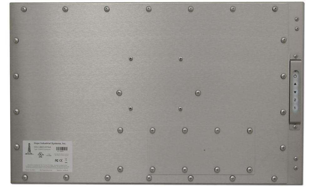
5 Mechanical Drawings Mechanical Drawings Front View mm (23.38") mm (20.22") mm (14.59") mm (11.44") Rear View mm (23.38") mm (14.59") 98.8 mm (3.89") CABLE ENTRY mm (9.50") UM23B User Manual, 99149, January
6 Mechanical Drawings Side View 71.2 mm (2.80") 34.3 mm (1.35") mm (7.30") KVM EXTENDER (optional) Side Mounting Holes 1/4"-20 Internal Thread x 0.625" Deep mm (4.87") mm (6.85") KEYBOARD (optional) 6 UM23B User Manual, 99149, January 2017
7 Installation Instructions Installation Instructions Step 1: Prepare for Installation IMPORTANT! Perform the following steps BEFORE installation of the monitor. 1. Ensure that sufficient power is available and a readily accessible disconnect device is incorporated in the building installation wiring. 2. Ensure that sufficient space is available to allow for proper air flow into and out of the unit. 3. Ensure that the air temperature around the unit (top and bottom) will not exceed the rated specifications of the unit.! ff ff The maximum rated temperature for the HIS-UM23 is 50 C (122 F). Remember that even though this product is designed to operate at 50 C, the life span of any electronic device is shortened when it is consistently operated at high temperatures. Therefore, it is wise to take steps to keep the temperature of the ambient air around the unit as low as possible. 4. Ensure that the ambient humidity of the air around the unit does not exceed the specifications of the unit. ff The maximum rated humidity for the HIS-UM23 is 90% non-condensing. UM23B User Manual, 99149, January
8 Installation Instructions Step 2: Bench-test Configuration Make sure everything works before installing into the production environment. TIP! If using a KVM extender, please refer to the installation instructions included with the KVM extender module. It is particularly important to bench-test the full configuration prior to final installation. This will help to identify and troubleshoot any system issues while configuration changes may still be easily made. Install Cable Connections The cable ports are located on the rear of the monitor. Refer to the following instructions to connect power, video, and touch screen (if applicable) to your monitor. Video Connection The HIS-UM23 supports digital video through its DVI port, and analog video through its VGA port. After selecting the appropriate interface, connect one end of your video cable to the input port on the rear of the monitor and the other end to the appropriate port on your host computer or other video source. TIP! If the video source has an HDMI or DisplayPort connection, this can be converted for use with the DVI video port using a simple adapter. If the video source has a 5 wire analog RGB video output, this can be converted for use with the VGA video port using a simple adapter. Contact Hope Industrial Systems for more information. Power Connection The HIS-UM23 is available with either AC or DC power input. 8 UM23B User Manual, 99149, January 2017
9 Installation Instructions AC power input models are powered by 100 to 240 VAC, 1.0/0.5 A, 60/50 Hz. Connect the AC power cable to the power input port on the rear of the monitor. Connect the other end into a nearby outlet. DC power input models are powered by 9.6 to 36.6 VDC, 2.5 to 0.65 A, Class 2 or SELV/LPS. Install Touch Screen Driver Applies to touch screen monitors only. Instructions below apply to Windows systems. Both Serial and USB ports are present on all touch screen monitors, but only one should be used to connect the touch screen interface to the monitor. All touch screen monitors are shipped with a CD-ROM that contains documentation and drivers for all major operating systems. To be sure that you have the most current information, please check the following Internet address: IMPORTANT! If you will be using a USB connection, install the touch screen driver first, and then connect the USB cable. If you will be using a Serial connection, connect the Serial cable first, and then install the touch screen driver. USB Connection 1. Select the appropriate driver for your operating system. a. If downloading from the web address listed above, select the appropriate driver for your operating system. b. If using the included CD, insert it into the host computer's CD-ROM drive. If the CD does not automatically run, browse the contents of the CD and open the READ.ME.FIRST.htm file in a web browser. Select the appropriate driver. 2. Click to "Run" the software when prompted. Follow on-screen instructions to download and execute the touch screen driver installation. 3. A cable retention bracket comes installed on the USB port on the rear of the monitor UM23B User Manual, 99149, January
10 Installation Instructions and will help to secure the cable and ensure adequate strain relief. Without removing the bracket, route one end of the USB cable through the retention bracket and connect it to the USB input port on the monitor. Connect the other end to the USB port on the host computer. Serial (RS-232) Connection 1. Connect one end of the Serial cable to the Serial input port on the rear of the monitor. Connect the other end to the Serial port on the host computer. Tighten the captive screws on the cable connectors to ensure adequate strain relief. 2. Select the appropriate driver for your operating system. a. If downloading from the web address listed above, select the appropriate driver for your operating system. b. If using the included CD, insert it into the host computer's CD-ROM drive. If the CD does not automatically run, browse the contents of the CD and open the READ.ME.FIRST.htm file in a web browser. Select the appropriate driver. 3. Click to "Run" the software when prompted. Follow on-screen instructions to download and execute the touch screen driver installation. Calibrate the Touch Screen Once the driver has finished installing, you are ready to calibrate the touch screen. Open the touch screen's Control Panel by clicking on the "Elo Touchscreen" icon, located in the host computer's Control Panel. Under the "General" tab, click the "Align" button to start the calibration routine. 10 UM23B User Manual, 99149, January 2017


11 Installation Instructions Step 3: Install the Monitor Once you have completed the full bench-test configuration and confirmed that all components are working properly, you are ready for final installation and mounting of the monitor.! WARNING! Hope Industrial will not assume liability for damage to internal electronics due to improper installation. Contact Hope Industrial if you need additional assistance. Fully Assembled Workstations If you purchased a fully assembled workstation, most of the assembly has already been performed for you. For your reference, complete installation instructions are shipped with the workstation should you need to disassemble or reassemble it for any reason. They may also be found on our website at the following address: Install Cable Exit Cover Plate Installation instructions vary slightly depending on the Cable Exit Cover Plate you ordered. Complete installation instructions are shipped with each Cover Plate configuration and may also be found on our website at the following addresses: Conduit Cable Exit (CP-CON Series): PermaGland (CP-PG Series): Pilot Hole Cover Plate (CP-BLNK Series): Compression Gland (CP-GL Series): Compression Gland (CP-RG Series): CP-RG1: CP-RG2: UM23B User Manual, 99149, January


12 Installation Instructions Mount the Monitor Hope Industrial Systems offers a variety of mounting options for your Universal Mount Monitor. Individual installation instructions are shipped with the following products and may also be found on our website at the addresses listed below. Heavy Industrial Yoke Mounts The standard yoke may be used alone, with our benchtop mounting kit for through-surface cable routing, or with our Pedestal Mount for free-standing applications. Complete installation instructions are shipped with the following products and may also be found on our website at the following addresses: Yoke Mounting Hardware: YB-N12-KIT (for YB -BLK-N12 Series): Yoke and Benchtop Mounting Kit (for YB Series): Heavy Industrial Pedestal Mounts Our Yoke and Pedestal Mount allows full range of pan and tilt motion, while our Fixed Pedestal Mount provides a sturdy solution when a non-adjustable mount is acceptable. Complete installation instructions are shipped with the following products and may also be found on our website at the following addresses: Fixed Pedestal: Yoke Mounting Hardware: YB-N12-KIT (for YB -BLK-N12 Series): Yoke and Benchtop/Pedestal Mounting Kit (for YB and PED4X4 Series): 12 UM23B User Manual, 99149, January 2017

: http://www.hopeindustrial.")


13 Installation Instructions Heavy Industrial Arm Mounts Our wall arm mounting options range from solid wall yoke to fully articulating arms. Complete installation instructions are shipped with the following products and may also be found on our website at the following addresses: Wall Mount Arms (for YA -15 and YA -24 Series): Wall Yoke (for YW -07 Series): VESA Radial Arm The VESA Radial Arm Mount is designed to suspend our Universal Mount Monitors above a working area. VESA Wall Mount Bracket The VESA Wall Mount Bracket allows simple, effective mounting of our Universal Mount Monitors to any vertical surface. VESA Benchtop Stand The VESA Benchtop Stand allows easy, stable positioning of our Universal Mount Monitors on any flat surface. UM23B User Manual, 99149, January
14 Installation Instructions All Hope Industrial Universal Mount Monitors come standard with a 100 mm square VESA mounting pattern with M4 threads. Below is the VESA mounting diagram for Hope Industrial Universal Mount Monitors. Detailed installation instructions for specific VESA mounting options are shipped with the product and may also be found on our website at the following address: IMPORTANT! If using VESA mounting screws not supplied by Hope Industrial Systems, ensure they do not intrude into the enclosure more than 12.7 mm (0.5"). VESA MOUNTING PATTERN (100 mm x 100 mm) MOUNTING PLATE UNIVERSAL MOUNT MONITOR M4 SCREWS NYLON WASHERS RUBBER WASHERS KEYBOARD (OPTIONAL) 14 UM23B User Manual, 99149, January 2017
15 Video Settings Video Settings Setting the Timing Mode Setting the timing mode of your computer graphics adapter (or other video source) is important for maximizing the quality of the screen image and for minimizing eye strain. The timing mode consists of the resolution (e.g x 1080) and refresh rate (or vertical frequency; e.g. 60 Hz). After setting the timing mode, use the On-Screen Display (OSD) controls to adjust the screen image. TIP! For the best picture quality, set your computer graphics adapter timing mode to: VESA 1920 x 60 Hz Please refer to the computer graphics adapter manufacturer's manual for instructions on setting the resolution and timing mode. In Microsoft Windows, these settings may be found at the following location: ff ff 2000, XP: Control Panel > Display > Settings Vista: Control Panel > Personalization > Display Settings ff Windows 7, 8, 10: Control Panel > Appearance and Personalization > Adjust Screen Resolution! WARNING! Do not set the graphics card in your computer to exceed the maximum refresh rate of 75 Hz; doing so may result in permanent damage to your display. UM23B User Manual, 99149, January

16 Video Settings Control Panel Buttons Use the control panel buttons located on the back of the monitor to display and adjust various settings on the On-Screen Display (OSD) menu. CONTROL PANEL BUTTONS 1. To display the Main Menu, press button [1]. NOTE: All OSD menus and adjustment screens disappear automatically after 15 seconds. This is adjustable through the OSD Time Out setting in the Setup menu. 2. To select a control to adjust, press the up [ ] or down [ ] button to scroll through the menu. 3. Press button [2] to open the menu for a selected control. 4. To adjust the control, press the up [ ] or down [ ] button. 5. To save the adjustments and return to the main OSD menu, press button [1] once. To exit the OSD menu, press button [1] twice. 16 UM23B User Manual, 99149, January 2017


![When the OSD menu IS displayed: Displays the control screen for the highlighted control. OSD and Power Lock Settings ff ff ff OSD Lock: Press and hold [1] and the up [ ] button for 10 seconds.](/docs-images/74/69650080/images/17-2.jpg "If any buttons are pressed the message OSD Locked will display for 3 seconds. OSD Unlock: Press and hold [1] and the up [ ] button again for 10 seconds.")
17 Video Settings Button Control Functions Power Turns the monitor on and off. The Power Indicator light glows blue during normal operation and orange when the monitor is in Power Saving mode. Menu Opens the OSD menu. Exits the OSD menu and saves adjustments. Up / Contrast Adjust Down / Brightness Adjust Enter When the OSD menu IS NOT displayed: Shortcut to Contrast Adjust. When the OSD menu IS displayed: Scrolls up and adjusts items in the menu up. When the OSD menu IS NOT displayed: Shortcut to Brightness Adjust. When the OSD menu IS displayed: Scrolls down and adjusts items in the menu down. When the OSD menu IS NOT displayed: Shortcut to toggle between analog and digital connection. When the OSD menu IS displayed: Displays the control screen for the highlighted control. OSD and Power Lock Settings ff ff ff OSD Lock: Press and hold [1] and the up [ ] button for 10 seconds. If any buttons are pressed the message OSD Locked will display for 3 seconds. OSD Unlock: Press and hold [1] and the up [ ] button again for 10 seconds. Power Button Lock: Press and hold [1] and the down [ ] button for 10 seconds. If the power button is pressed, the message Power Button Locked will display for 3 seconds. With or without this setting, after a power failure, your monitor's power will automatically turn ON when power is restored. f f Power Button Unlock: Press and hold [1] and the down [ ] button again for 10 seconds. UM23B User Manual, 99149, January
![Video Settings On-Screen Display (OSD) Menus To open the OSD menu, press button [1] once.](/docs-images/74/69650080/images/18-0.jpg "The following screen will appear: Main Menu Auto Image Adjust Contrast / Brightness Input Select Color Adjust Information Manual Image Adjust Setup Menu Memory Recall Description Automatically sizes,")
18 Video Settings On-Screen Display (OSD) Menus To open the OSD menu, press button [1] once. The following screen will appear: Main Menu Auto Image Adjust Contrast / Brightness Input Select Color Adjust Information Manual Image Adjust Setup Menu Memory Recall Description Automatically sizes, centers, and fine tunes the video signal to eliminate waviness and distortion. Includes the Contrast and Brightness functions. Allows the user to toggle between inputs. Provides several color adjustment modes. Displays the timing mode (video signal input). Includes the H / V Position, Horizontal Size, Fine Tune, Sharpness, Dynamic Contrast, Aspect Ratio, and ECO Mode functions. Includes the Language Select, Resolution Notice, OSD Position, OSD Time Out, OSD Background, Auto Power Off, and Power Indicator functions. Returns adjustments back to factory settings. 18 UM23B User Manual, 99149, January 2017

19 Auto Image Adjust Menu The Auto Image Adjust menu automatically sizes, centers, and fine tunes the video signal to eliminate waviness and distortion. Video Settings NOTE: Auto Image Adjust works with most common video cards. If this function does not work on your display, lower the video refresh rate to 60 Hz and set the resolution to its pre-set value. Contrast / Brightness Menu The Contrast / Brightness menu includes the Contrast and Brightness functions. Contrast / Brightness Menu Description Contrast Adjusts the difference between the image background (black level) and the foreground (white level). This feature may also be accessed by pressing the up [ ] button outside of the OSD menu. Brightness Adjusts the background black level of the screen image. This feature may also be accessed by pressing the down [ ] button outside of the OSD menu. Input Select Menu The Input Select menu allows the user to toggle between inputs if there is more than one computer connected to the display. Use D-Sub for analog VGA signals and DVI for digital signals. UM23B User Manual, 99149, January
, green (G), and blue (B). The factory setting for this product is Native.")
20 Video Settings Color Adjust Menu The Color Adjust menu provides several color adjustment modes, including preset color temperatures and a User Color mode which allows independent adjustment of red (R), green (G), and blue (B). The factory setting for this product is Native. Color Adjust Menu srgb Description This is quickly becoming the industry standard for color management, with support being included in many of the latest applications. Enabling this setting allows the LCD to more accurately display colors the way they were originally intended. NOTE: Enabling the srgb setting will cause the Contrast and Brightness adjustments to be disabled. Bluish Cool Native Warm User Color Adds blue to the screen image for cooler white (used in most office settings with fluorescent lighting). Adds blue to the screen image for cooler white (used in most office settings with fluorescent lighting). Adds red to the screen image for warmer white and richer red. Adds red to the screen image for warmer white and richer red. Individual adjustments for red (R), green (G), and blue (B). 1. To select color (R, G, or B) press button [2]. 2. To adjust selected color, press the up [ ] or down [ ] button. NOTE: If you select RECALL from the OSD Main Menu when the product is set to a Preset Timing Mode, colors return to the Native factory preset. 20 UM23B User Manual, 99149, January 2017
21 Information Menu Video Settings The Information menu displays the timing mode (video signal input) coming from the graphics card in the computer. See your graphics card's user guide for instructions on changing the resolution and refresh rate (vertical frequency). NOTE: VESA 1920 x 60 Hz (recommended) means that the resolution is 1920 x 1080 and the refresh rate is 60 Hz. Manual Image Adjust Menu The Manual Image Adjust menu includes the H / V Position, Horizontal Size, Fine Tune, Sharpness, Dynamic Contrast, Aspect Ratio, and ECO Mode functions. Manual Image Adjust Menu H / V Position Horizontal Size Fine Tune Description Moves the screen image left or right and up or down. Adjusts the width of the screen image. Sharpens the focus by aligning text and/or graphics with pixel boundaries. NOTE: Try the Auto Image Adjust function first. Sharpness Adjusts the clarity and focus of the screen image. UM23B User Manual, 99149, January
.")
22 Video Settings Manual Image Adjust Menu Dynamic Contrast Aspect Ratio ECO Mode Description Allows the user to turn the contrast ratio enhancement On or Off. Dynamic Contrast adjusts the brightness of the backlights to improve the contrast of the screen image (darker screen images will have better black levels). Selects the image size for 4:3 or full screen. Provides lower power consumption by reducing the brightness. Standard is the default brightness setting Optimize reduces brightness by 25% Conserve reduces brightness by 50% Setup Menu The Setup menu includes the Language Select, Resolution Notice, OSD Position, OSD Time Out, OSD Background, Auto Power Off, and Power Indicator functions. 22 UM23B User Manual, 99149, January 2017
23 Video Settings Setup Menu Language Select Resolution Notice OSD Position OSD Time Out OSD Background Auto Power Off Power Indicator Description Allows the user to choose the language used in the menus and control screens. Advises the optimal resolution to use. Allows the user to move the OSD menus and control screens. Sets the length of time the OSD screen is displayed. For example, with a "15 second" time setting, if a control is not pushed within 15 seconds, the display screen disappears. Allows the user to turn the OSD background On or Off. When enabled, this setting will automatically power off the monitor when no signal is detected for 3 minutes. Allows the user to select the Power Indicator On/Off for Power On/Off mode. Memory Recall Menu The Memory Recall menu returns adjustments back to factory settings. NOTE: This control does not affect changes made with the Language Select or Power Lock setting. UM23B User Manual, 99149, January
24 Cleaning Instructions Cleaning Instructions! CAUTION! DO NOT USE ABRASIVE MATERIALS, SUCH AS PAPER TOWELS OR DIRTY SHOP RAGS, ON THE DISPLAY AS IT WILL SCRATCH THE PROTECTIVE COATING. ALWAYS USE A SOFT CLOTH, PREFERABLY MADE OF COTTON. All displays may be cleaned using any standard glass cleaner as long as there is no abrasive or oily content. Vinegar or ammonia will not hurt the screen. The anti-reflective coatings on glass window-equipped displays are physically part of the surface of the glass and resist degradation to the Military Specifications. To minimize over-run of cleaning solution, spray the cloth first and then clean the screen. 24 UM23B User Manual, 99149, January 2017
25 Troubleshooting Troubleshooting Video Troubleshooting IMPORTANT! If using a KVM extender, first try to resolve any problems using the solutions listed below. If the problem still exists, try bypassing the KVM extender. If this fixes the problem and allows the monitor to work properly, then the KVM extender is the source of the problem. Please refer to the troubleshooting section of the KVM extender manual or contact Hope Industrial Systems for additional assistance. Symptom Causes Solutions No image on the screen and control's Power Indicator light is not lit No image on the screen and control's Power Indicator light is lit orange Screen image is dim Monitor is not powered on. Press the Power button on the monitor and make sure the Power Indicator light is lit blue. Check power connections at the monitor and power source. For DC models, check the connector polarity and ensure input voltage is 9.6 to 36.6 VDC. The "Auto Power Off" function is enabled. Video cable is not plugged in correctly. PC is in Power Saving mode. PC is not powered on. PC is not sending signal. Brightness and/or contrast settings are not set properly. Disable this setting by unchecking the box for the "Auto Power Off" function in the OSD's "Setup" menu. Check the video cable connection at the monitor, PC, and/or KVM extender. Power Saving mode can usually be exited by moving the mouse. Ensure PC is powered on. Connect the PC to another known working monitor to check the PC source signal. Adjust the monitor's brightness and contrast settings in the OSD's "Contrast / Brightness" menu. UM23B User Manual, 99149, January
26 Troubleshooting Symptom Causes Solutions "Out of Range" message box and no image on the screen "No Signal" message box and no image on the screen Incorrectly displayed or partial image on the screen Wrong or abnormal colors (white is not white) The message "OSD Locked" appears The message "Power Button Locked" appears The source signal exceeds the maximum resolution and/or refresh rate that the monitor can handle ( > 1920 x 1080 resolution or > 75 Hz refresh rate). Video cable is not plugged in correctly. PC is in Power Saving mode. PC is not powered on. PC is not sending signal. Monitor has not been adjusted correctly for the source signal. Monitor color settings are incorrectly adjusted. Video cable is not securely connected. Video cable is bad. The OSD has been locked to prevent unauthorized changes to display settings. The Power button has been locked to prevent unauthorized shut down of the monitor. Adjust the computer settings to the monitor's native resolution: 1920 x 60 Hz Check the video cable connection at the monitor, PC, and/or KVM extender. Power Saving mode can usually be exited by moving the mouse. Ensure PC is powered on. Connect the PC to another known working monitor to check the PC source signal. Activate the "Auto Image Adjust" function in the OSD menu. Fine tune the picture by manually adjusting the image. In the OSD menu, these functions can be found in the "Manual Image Adjust" menu. Reset the monitor to the factory default settings by activating the "Memory Recall" function in the OSD. If any colors (red, green, or blue) are missing, check the video cable to make sure it is securely connected. Check to make sure there are no loose or broken pins in the cable connector. Shorts in the cable could also cause an improper image to display. Press and hold [1] and the up [ ] button for 10 seconds. Press and hold [1] and the down [ ] button for 10 seconds. 26 UM23B User Manual, 99149, January 2017
27 Troubleshooting Touch Screen Troubleshooting Applies to touch screen monitors only. To be sure that you have the most current driver, please check the following Internet address: Symptom Causes Solutions No response when touching the touch screen The cursor moves but does not follow my finger when touching the touch screen Touch screen driver has not been installed. Touch screen cable is not plugged in correctly. If using a USB connection, does the USB cable length exceed 3 meters? If using a Serial connection, is the Serial cable plugged into the correct COM port? Touch screen driver has not been installed. Touch screen has not been calibrated. Download and install the latest driver from the Hope Industrial website. Make sure either the USB or Serial cable is securely connected to the monitor and PC. Do not connect both. USB cables have a 3 meter limitation and could cause no touch response if this is exceeded. Ensure that the Serial cable is connected to the COM port being used prior to installing the touch screen driver. Download and install the latest driver from the Hope Industrial website. Activate the calibration utility. In Windows systems, these settings may be found at the following location: Control Panel > Elo Touchscreen > "General" Tab Press the Align button. Touch all targets as the appear to calibrate the touch screen. Press the Green Check button when verified. UM23B User Manual, 99149, January
28 Specifications Specifications Display Type Size Thin-film transistor (TFT) Active Matrix Liquid Crystal 23" diagonal Image Size (W x H) mm x mm (20.05" x 11.28") Native Resolution Minimum Resolution VGA (640 x 480) Pixel Pitch Number of Colors Full HD 1080p (1920 x 1080, 16:9 aspect ratio) mm x mm 16.7 million Brightness (white) 250 nits (cd/m 2 ) Viewing Angle (Hori/Vert) 178 / 178 Contrast Ratio (typical) Backlight (typical) Environmental Operating Temperature Storage Temperature Humidity Operating Shock Operating Vibration (sine) Transport Vibration (random) 1000:1 (static); 20,000,000:1 (dynamic) LED; 40,000 hour brightness half-life 0 to 50 C (32 to 122 F) -20 to 60 C (-4 to 140 F) 20% to 90% non-condensing 15 g, 6 msec, half-sine 1.0g, swept sine Hz 0.1g 2 / Hz, Hz 0.03g 2 / Hz, Hz Altitude Operating: up to 10,000 feet Electrical Non-operating: up to 40,000 feet Monitor Input AC power models 100 to 240 VAC, 1.0/0.5 A, 60/50 Hz Power Consumption Power Consumption (Standby mode) DC power models 9.6 to 36.6 VDC, 2.5 to 0.65 A, Class 2 or SELV/LPS ~ 24 W < 1 W 28 UM23B User Manual, 99149, January 2017
29 Specifications Video Input Connectors HD-15, DVI-D Compatible inputs using optional adapter (call for details): HDMI (via HDMI to DVI adapter) DisplayPort (via DisplayPort to DVI adapter) BNC (via HD-15 to 5-wire BNC adapter) Input Signal Formats RGB Analog video, 0.7/1.0 Vp-p, 75 Ohms Horizontal Scan Vertical Scan Supported Video Standards Response Rate (typical) Compatible sync modes: Separate H/V sync DVI NOTE: NTSC/PAL composite input available (call for details) khz Hz 60 Hz 60 Hz 60 Hz 60 Hz 60 Hz 60, 75 Hz 60 Hz 60 Hz 60, 75 Hz 50, 60, 75 Hz 50, 60, 75 Hz 50, 60, 75 Hz 50, 60 Hz 66 Hz 5 ms 75 Hz 60, 75 Hz 50, 60, 70, 72, 75 Hz 60 Hz 75 Hz 60 Hz 56, 60, 72, 75 Hz 60 Hz 50 Hz 60 Hz 70 Hz 50, 60, 67, 72, 75 Hz 60, 70 Hz 70 Hz Functional Control Panel Buttons On-Screen Display (OSD) Menus Touch Screen Option Power, 1 (Menu), Up, Down, 2 (Enter) Auto Image Adjust, Contrast / Brightness, Input Select, Color Adjust, Information, Manual Image Adjust, Setup, Memory Recall 5-wire resistive system; emulates a mouse; Serial (RS-232) and USB interface to host computer UM23B User Manual, 99149, January
30 Specifications Physical Enclosure Type Enclosure Rating Self-contained enclosure Built to IP22 standards NEMA/UL Type 2 (Black Powder-Coated or Stainless Steel) Enclosure Dimensions (W x H x D) Built to IP65/IP66 standards NEMA/UL Type 12/4 (Black Powder-Coated Steel) NEMA/UL Type 12/4/4X (Stainless Steel) mm x mm x 82.6 mm (23.38" x 14.59" x 3.25") Net Weight Black Powder-Coated Carbon Steel model 17 lbs. Stainless Steel model 22 lbs. Shipping Weight Black Powder-Coated Carbon Steel model 22 lbs. Stainless Steel model 27 lbs. Compliances and Certifications Electrical UL rd Edition / cul Listed Product (File No. E212889) FCC Class A CAN ICES-3A/NMB-3A CE Environmental IEC (Reliability) Enclosure UL 50E (File No. E212889) WEEE (Registration No. WEE/DJ1859ZX for UK only) Hazardous Location For monitors with model numbers HIS-UM23- HB only: UL Rated for Hazardous Locations: I.T.E. Listed for Class I, Division 2 for Groups A, B, C, and D; Class II, Division 2 for Groups F and G; Class III; Temp Code T5 (File No. E334953) per ANSI/ISA For monitors with model numbers HIS-UM23- UB only: UL Rated for Hazardous Locations: I.T.E. Listed for Class I, Division 2 for Groups A, B, C, and D; Class II, Division 2 for Groups F and G; Class III; Temp Code T4A (File No. E334953) per ANSI/ISA UM23B User Manual, 99149, January 2017
31 Warranty Statement Warranty Statement Who is Covered? This warranty covers the purchaser of this product only and is not transferable without our written consent. What Does This Warranty Cover and What is the Period of Coverage? We warrant this product to be free from defects in material and workmanship, subject to the conditions set forth below. The warranty on all industrial display products, KB-R2 and KB-M2 keyboard series, KVM2 extender series, and ENCL-TC and ENCL-PC enclosure series remains in force for a three year period beginning on the date we invoice you. The warranty period on KB-PL1 keyboards is two years, and all other keyboards carry a one year warranty. If Hope Industrial Systems repairs or replaces a product under warranty, its warranty term is not extended. What Will We Do to Correct Problems and How Do You Get Service? We will repair or replace (at our sole option) any part of the unit which proves to be defective. Replacement parts may be new or refurbished and will meet the same specifications of the original parts or unit. For orders sold through our U.S. operations, at our expense we will return the product to any location within the U.S.A. via the shipping method of our choice. Shipping fees for products returned to customers outside the U.S.A. are the responsibility of the customer. For products originally sold through Hope Industrial U.K., return shipping to and from Hope Industrial repair facilities and any EU member country (except Croatia, Cyprus, and Malta) will be provided using a pre-paid UPS shipping label sent via . In order to receive warranty service you must get prior approval from Hope Industrial Systems. To request warranty service you can telephone us at or +44 (0) in the United Kingdom or send an to support@hopeindustrial.com. If we determine that warranty service is needed we will give you a Return Material Authorization (RMA) number. This RMA number must be conspicuously marked on the outside of the shipping box. Hope Industrial Systems will not accept shipments not accompanied by the RMA number. Except where otherwise noted, you must ship or deliver the product to Hope Industrial Systems Freight prepaid. What Does This Warranty Not Cover? This warranty does not cover equipment which has been damaged due to misuse, abuse, or accident such as: operating the equipment outside of published specifications; exposure to chemicals or gases not covered by specified NEMA standards; displaying fixed images for long periods of time resulting in afterimage effects; improper or unauthorized repair by anyone other than Hope Industrial Systems or a service agency authorized by Hope Industrial Systems to perform such repairs; fire, flood, acts of God, or other contingencies beyond the control of Hope Industrial Systems. Hope Industrial Systems responsibility for malfunctions and defects in hardware is limited to repair and replacement as set forth in this warranty statement. Hope Industrial Systems shall not be liable for direct, indirect, incidental, consequential, or other types of damages resulting from the use of any Hope Industrial Systems product other than the liability stated above. These warranties are in lieu of all other warranties express or implied, including, but not limited to, the implied warranties of merchantability or fitness for a particular purpose. Some states do not allow the exclusion of implied warranties or the limitation or exclusion of liability for incidental or consequential damages so the above exclusions or limitations may not apply to you. You are cautioned that the performance of this product can be affected by many factors, such as system configuration, software, application, and operator control of the system. It is your responsibility to determine suitability of this product for your purpose and application. UM23B User Manual, 99149, January
32 Hope Industrial Systems, Inc. US / International 1325 Northmeadow Parkway Suite 100 Roswell, GA United States Toll Free: (877) International: +1 (678) Fax: +1 (678) Sales and Customer Service: sales@hopeindustrial.com Support and Returns: support@hopeindustrial.com Accounting Department: accounting@hopeindustrial.com UK Harling Road Snetterton Norwich NR16 2JU United Kingdom Phone: +44 (0) Fax: +44 (0) Sales and Customer Service: sales@hopeindustrial.co.uk Support and Returns: support@hopeindustrial.co.uk Accounting Department: accounting@hopeindustrial.co.uk 32 UM23B User Manual, 99149, January Hope Industrial Systems, Inc.
19" RACK MOUNT INDUSTRIAL MONITOR REVISION F USER MANUAL
 19" RACK MOUNT INDUSTRIAL MONITOR REVISION F USER MANUAL Model No. HIS-RL19- _ F Table of Contents Safety and Regulatory Information 3 FCC Notice 3 Hazardous Locations 4 Waste Electrical and Electronic
23" UNIVERSAL MOUNT INDUSTRIAL MONITOR REVISION D USER MANUAL
 23" UNIVERSAL MOUNT INDUSTRIAL MONITOR REVISION D USER MANUAL Model No. HIS-UM23- _ D Table of Contents Safety and Regulatory Information...3 FCC Notice...3 Hazardous Locations...4 Waste Electrical and
23" PANEL MOUNT INDUSTRIAL MONITOR REVISION C USER MANUAL
 23" PANEL MOUNT INDUSTRIAL MONITOR REVISION C USER MANUAL Model No. HIS-ML23- _ C Table of Contents Safety and Regulatory Information...3 FCC Notice...3 Hazardous Locations...4 Waste Electrical and Electronic
19" RACK MOUNT INDUSTRIAL MONITOR REVISION H USER MANUAL
 19" RACK MOUNT INDUSTRIAL MONITOR REVISION H USER MANUAL Model No. HIS-RL19- _ H Table of Contents Safety and Regulatory Information...3 FCC Notice... 3 Hazardous Locations... 4 Waste Electrical and Electronic
19" PANEL MOUNT INDUSTRIAL MONITOR REVISION F USER MANUAL
 19" PANEL MOUNT INDUSTRIAL MONITOR REVISION F USER MANUAL Model No. HIS-ML19- _ F Table of Contents Safety and Regulatory Information 3 FCC Notice 3 Hazardous Locations 4 Waste Electrical and Electronic
22" PANEL MOUNT INDUSTRIAL MONITOR REVISION B USER MANUAL
 22" PANEL MOUNT INDUSTRIAL MONITOR REVISION B USER MANUAL Model No. HIS-ML22- _ B Table of Contents Safety and Regulatory Information...3 FCC Notice...3 Hazardous Locations...4 Waste Electrical and Electronic
19.5" PANEL MOUNT INDUSTRIAL MONITOR REVISION A USER MANUAL
 19.5" PANEL MOUNT INDUSTRIAL MONITOR REVISION A USER MANUAL Model No. HIS-ML19.5- _ A Table of Contents Safety and Regulatory Information...3 FCC Notice...3 Hazardous Locations...4 Waste Electrical and
19" PANEL MOUNT INDUSTRIAL MONITOR REVISION H USER MANUAL
 19" PANEL MOUNT INDUSTRIAL MONITOR REVISION H USER MANUAL Model No. HIS-ML19- _ H Table of Contents Safety and Regulatory Information...3 FCC Notice...3 Hazardous Locations...4 Waste Electrical and Electronic
20" PANEL MOUNT INDUSTRIAL MONITOR REVISION C USER MANUAL
 20" PANEL MOUNT INDUSTRIAL MONITOR REVISION C USER MANUAL Model No. HIS-ML20- _ C Table of Contents Safety and Regulatory Information...3 FCC Notice...3 Waste Electrical and Electronic Equipment Directive
15" RACK MOUNT INDUSTRIAL MONITOR REVISION H USER MANUAL
 15" RACK MOUNT INDUSTRIAL MONITOR REVISION H USER MANUAL Model No. HIS-RL15- _ H Table of Contents Safety and Regulatory Information...3 FCC Notice...3 Hazardous Locations...4 Waste Electrical and Electronic
17" PANEL MOUNT INDUSTRIAL MONITOR REVISION H USER MANUAL
 17" PANEL MOUNT INDUSTRIAL MONITOR REVISION H USER MANUAL Model No. HIS-ML17- _ H Table of Contents Safety and Regulatory Information...3 FCC Notice...3 Hazardous Locations...4 Waste Electrical and Electronic
15" PANEL MOUNT INDUSTRIAL MONITOR REVISION H USER MANUAL
 15" PANEL MOUNT INDUSTRIAL MONITOR REVISION H USER MANUAL Model No. HIS-ML15- _ H Table of Contents Safety and Regulatory Information...3 FCC Notice...3 Hazardous Locations...4 Waste Electrical and Electronic
Hope Industrial Systems, Inc. User Manual. 12 Panel Mount Industrial Monitor Revision C. Model Numbers: HIS-ML12- _ C
 Hope Industrial Systems, Inc. User Manual 12 Panel Mount Industrial Monitor Revision C Model Numbers: HIS-ML12- _ C Table of Contents SAFETY AND REGULATORY INFORMATION... 3 Warning... 3 FCC Notice... 3
Hope Industrial Systems, Inc. User Manual. 17 Rack Mount Industrial Monitor Revision D. Model No. HIS-RL17- _ D
 Hope Industrial Systems, Inc. User Manual 17 Rack Mount Industrial Monitor Revision D Model No. HIS-RL17- _ D Table of Contents SAFETY AND REGULATORY INFORMATION... 3 Warning... 3 FCC Notice... 3 CONTROL
Hope Industrial Systems, Inc. User Manual. 19 Universal Mount Industrial Monitor. Model No. HIS-WL19- A
 Hope Industrial Systems, Inc. User Manual 19 Universal Mount Industrial Monitor Model No. HIS-WL19- A 1 TABLE OF CONTENTS Safety and Regulatory Information... 3 Using the LCD Display... 4 Adjusting the
Hope Industrial Systems, Inc. User Manual. 18 Panel Mount Industrial Monitor. Model No. HIS-ML18-xxxC
 Hope Industrial Systems, Inc. User Manual 18 Panel Mount Industrial Monitor Model No. HIS-ML18-xxxC 1 TABLE OF CONTENTS Safety and Regulatory Information...3 Using the LCD Display...4 Adjusting the Screen
Hope Industrial Systems, Inc. User Manual. 17 Panel Mount Industrial Monitor Revision A. Model Numbers: HIS-ML17- _ A
 Hope Industrial Systems, Inc. User Manual 17 Panel Mount Industrial Monitor Revision A Model Numbers: HIS-ML17- _ A TABLE OF CONTENTS Safety and Regulation Information... 3 Factory Preset Timing... 4 Control
Hope Industrial Systems, Inc. User Manual. 17 Panel Mount Industrial Monitor Revision D. Model No. HIS-ML17- _ D
 Hope Industrial Systems, Inc. User Manual 17 Panel Mount Industrial Monitor Revision D Model No. HIS-ML17- _ D Table of Contents SAFETY AND REGULATORY INFORMATION... 3 Warning... 3 FCC Notice... 3 CONTROL
PL2410W LCD Monitor USER'S GUIDE.
 PL2410W LCD Monitor USER'S GUIDE www.planar.com Content Operation Instructions...1 Safety Precautions...2 First Setup...3 Front View of the Product...4 Rear View of the Product...5 Quick Installation...6
PLL2210MW LED Monitor
 PLL2210MW LED Monitor USER'S GUIDE www.planar.com Content Operation Instructions...1 Safety Precautions...2 First Setup...3 Front View of the Product...4 Rear View of the Product...5 Quick Installation...6
22" Touchscreen LED Monitor USER'S GUIDE
 22" Touchscreen LED Monitor USER'S GUIDE Content Operation Instructions...1 Unpacking Instructions...2 Safety Precautions...2 Front View of the Product...3 Rear View of the Product...4 Quick Installation...5
PXL2470MW LED LCD Monitor
 PXL2470MW LED LCD Monitor USER'S GUIDE www.planar.com Content Operation Instructions...1 Unpacking Instructions...2 Safety Precautions...2 Package Overview...3 First Setup...4 Front View of the Product...5
PXL2760MW LED LCD Monitor
 PXL2760MW LED LCD Monitor USER'S GUIDE www.planar.com Content Operation Instructions...1 Safety Precautions...2 Package Overview...3 First Setup...4 Front View of the Product...5 Rear View of the Product...6
USER MANUAL. 22" Class Slim HD Widescreen Monitor L215DS
 USER MANUAL 22" Class Slim HD Widescreen Monitor L215DS TABLE OF CONTENTS 1 Getting Started Package Includes Installation 2 Control Panel / Back Panel Control Panel Back Panel 3 On Screen Display 4 Technical
PLL2710W LED LCD Monitor
 PLL2710W LED LCD Monitor USER'S GUIDE www.planar.com Content Operation Instructions...1 Safety Precautions...2 Package Overview...3 First Setup...4 Front View of the Product...5 Rear View of the Product...6
USER MANUAL. 27 Full HD Widescreen LED Monitor L27ADS
 USER MANUAL 27 Full HD Widescreen LED Monitor L27ADS TABLE OF CONTENTS 1 Getting Started 2 Control Panel/ Back Panel 3 On Screen Display 4 Technical Specs 5 Care & Maintenance 6 Troubleshooting 7 Safety
Introduction...2. Features...2 Safety Precautions...2. Installation...4
 PE1900 Contents Introduction...2 Features...2 Safety Precautions...2 Installation...4 Unpacking the Display...4 Locations and Functions of Controls...4 Connections...5 Using Your Display...7 Turning the
USER MANUAL. 27 Full HD Widescreen LED Monitor L270E
 USER MANUAL 27 Full HD Widescreen LED Monitor L270E TABLE OF CONTENTS 1 Getting Started 2 Control Panel/ Back Panel 3 On Screen Display 4 Technical Specs 5 Care & Maintenance 6 Troubleshooting 7 Safety
USER MANUAL. 27" 2K QHD LED Monitor L27HAS2K
 USER MANUAL 27" 2K QHD LED Monitor L27HAS2K TABLE OF CONTENTS 1 Getting Started 2 Control Panel/ Back Panel 3 On Screen Display 4 Technical Specs 5 Troubleshooting 6 Safety Info & FCC warning 1 GETTING
PLL1920M LED LCD Monitor
 PLL1920M LED LCD Monitor USER'S GUIDE www.planar.com Content Operation Instructions...1 Safety Precautions...2 First Setup...3 Front View of the Product...4 Rear View of the Product...5 Installation...6
USER MANUAL. 28" 4K Ultra HD Monitor L28TN4K
 USER MANUAL 28" 4K Ultra HD Monitor L28TN4K TABLE OF CONTENTS 1 Getting Started 2 Control Panel/ Back Panel 3 On Screen Display 4 Technical Specs 5 Care & Maintenance 6 Troubleshooting 7 Safety Info &
USER MANUAL Full HD Widescreen LED Monitor L215ADS
 USER MANUAL 21.5 Full HD Widescreen LED Monitor L215ADS TABLE OF CONTENTS 1 Getting Started 2 Control Panel/ Back Panel 3 On Screen Display 4 Technical Specs 5 Care & Maintenance 6 Troubleshooting 7 Safety
USER MANUAL Full HD Widescreen LED Monitor L215IPS
 USER MANUAL 21.5 Full HD Widescreen LED Monitor L215IPS TABLE OF CONTENTS 1 Getting Started 2 Control Panel/ Back Panel 3 On Screen Display 4 Technical Specs 5 Care & Maintenance 6 Troubleshooting 7 Safety
19 / 20.1 / 22 WIDE SCREEN TFT-LCD MONITOR
 19 / 20.1 / 22 WIDE SCREEN TFT-LCD MONITOR V193/ V220 Series V202 Series USER MANUAL www.viewera.com Rev. 2.0 Table of Contents EMC Compliance......1 Important Precautions...2 1. Package contents....3
USER MANUAL Full HD Widescreen LED Monitor L236VA
 USER MANUAL 23.6 Full HD Widescreen LED Monitor L236VA TABLE OF CONTENTS 1 Getting Started 2 Control Panel/ Back Panel 3 On Screen Display 4 Technical Specs 5 Care & Maintenance 6 Troubleshooting 7 Safety
User Manual MODEL: KK1500-TR. Touch Display LCD Monitor. Installation Guide. 15 Resistive Touch LCD Monitor
 Touch Display LCD Monitor User Manual Installation Guide 15 Resistive Touch LCD Monitor MODEL: KK1500-TR i-tech Company LLC TOLL FREE: (888) 483-2418 EMAIL: info@itechlcd.com WEB: www.itechlcd.com User
DCL9AW. User Manual. English
 DCL9AW User Manual English PRECAUTIONS Information for users applicable in European Union countries 1 Information for users applicable in United States of America 1 Installation 1 Power connection 1 Maintenance
Dell D3218HN. User s Guide. Regulatory model: D3218HNo
 Dell D3218HN User s Guide Regulatory model: D3218HNo Notes, cautions, and warnings NOTE: A NOTE indicates important information that helps you make better use of your computer. CAUTION: A CAUTION indicates
QuickSpecs. Models RB146AA#ABA Standard Configuration RB146AT#ABA Promotional Part Number (SmartBuy) HP L5006tm 15-inch LCD Touchscreen Monitor
 HP L5006tm 15-inch LCD Touchscreen Monitor") Overview 1. 2. 3. 4. 5. Power: Turns the unit on and off. Select: Selects the adjustment items from the on-screen display (OSD) menus. Arrow down: Enter brightness adjustment, decrease value of the adjustment
Overview 1. 2. 3. 4. 5. Power: Turns the unit on and off. Select: Selects the adjustment items from the on-screen display (OSD) menus. Arrow down: Enter brightness adjustment, decrease value of the adjustment
LCD VALUE SERIES (32 inches)
") LCD VALUE SERIES (32 inches) http://www.orionimages.com All contents of this document may change without prior notice, and actual product appearance may differ from that depicted herein 1. SAFETY INSTRUCTION
LCD VALUE SERIES (32 inches) http://www.orionimages.com All contents of this document may change without prior notice, and actual product appearance may differ from that depicted herein 1. SAFETY INSTRUCTION
LA1500R USER S GUIDE.
 LA1500R USER S GUIDE www.planar.com The information contained in this document is subject to change without notice. This document contains proprietary information that is protected by copyright. All rights
User Guide. Single-Link DVI Active Cable Extender. DVI-7171c
 User Guide Single-Link DVI Active Cable Extender DVI-7171c TABLE OF CONTENTS SECTION PAGE PRODUCT SAFETY...1 PRODUCT LIABILITY...1 1.0 INTRODUCTION...2 2.0 SPECIFICATIONS...3 3.0 PACKAGE CONTENTS...4 4.0
User Guide. 20 Widescreen LED Monitor NS-20EM50A13
 User Guide 20 Widescreen LED Monitor NS-20EM50A13 Contents Introduction.....................................................1 Safety Precautions...............................................1 WARNINGS:......................................................
User Manual. PC / HD Scaler. with advanced video processing. VGA to Component Video Component Video to VGA VGA to VGA Component to Component
 User Manual PC / HD Scaler with advanced video processing VGA to Component Video Component Video to VGA VGA to VGA Component to Component Model 1366 WARNINGS Read these instructions before installing or
User Manual MODEL: KKF1500-PCAP. True FLAT P-CAP LCD Monitor. Installation Guide. 15 True FLAT P-CAP Touch LCD Monitor
 True FLAT P-CAP LCD Monitor User Manual Installation Guide 15 True FLAT P-CAP Touch LCD Monitor MODEL: KKF1500-PCAP i-tech Company LLC TOLL FREE: (888) 483-2418 EMAIL: info@itechlcd.com WEB: www.itechlcd.com
17 19 PROFESSIONAL LCD COLOUR MONITOR ART
 17 19 PROFESSIONAL LCD COLOUR MONITOR ART. 41657-41659 Via Don Arrigoni, 5 24020 Rovetta S. Lorenzo (Bergamo) http://www.comelit.eu e-mail:export.department@comelit.it WARNING: TO REDUCE THE RISK OF FIRE
VGA Extender over Single CAT 6 Cable with Audio Support. Model Extend both video and audio up to 1000 feet
 VGA Extender over Single CAT 6 Cable with Audio Support Model 103004 Extend both video and audio up to 1000 feet Utilize a Cat 6 cable instead of a bulky VGA cable Supports a local monitor and local speakers
It will cause malfunction if the monitor is operating with unspecified power supply
 User Manual / Installation Guide Model No. PTM-1525R/RT Warning! It will cause malfunction if the monitor is operating with unspecified power supply unit or incorrect power voltage. Do not exposure this
INFORMATION TO THE USER
 U.S.FEDERAL COMMUNICATIONS COMMISSION RADIO FREQUENCY INTERFERENCE STATEMENT INFORMATION TO THE USER NOTE: This equipment has been tested and found to comply with the limits for a Class B digital device
H270 LED MONITOR USER MANUAL
 H270 LED MONITOR USER MANUAL In order to continue serving our customers and providing the best products, our product information including our user manuals may receive updates from time to time. Please
Table of Contents Precautions... 2
 Table of Contents Precautions... 2 Special notes on LCD monitors... 2 Package contents... 3 Installation instructions... 3 Assembling the monitor... 3 Adjusting the viewing angle... 4 Connecting the devices...
DA1909 COMPUTER VIDEO LINE DRIVER WITH EQUALIZATION USER S GUIDE
 MANUAL PART NUMBER: 400-0108-002 PRODUCT REVISION: 1 COMPUTER VIDEO LINE DRIVER WITH EQUALIZATION USER S GUIDE INTRODUCTION Altinex appreciates your purchase of the Line Driver. We are sure you will find
User Manual 15" LCD Open frame SAW Touch Monitor KOT-0150US-SA4W. Table of Contents
 User Manual 15" LCD Open frame SAW Touch Monitor KOT-0150US-SA4W Table of Contents Chapter 1. Introduction...2 1.1 Product Description 1.2 About the Product Chapter 2. Installation and Setup...2 2.1 Unpacking
Operation Manual 1T-TG-PCHD Analog Test Generator 1T-TG-DVI DVI Test Generator
 99 Washington Street Melrose, MA 02176 Phone 781-665-1400 Toll Free 1-800-517-8431 Visit us at www.testequipmentdepot.com Operation Manual 1T-TG-PCHD Analog Test Generator 1T-TG-DVI DVI Test Generator
2013, 2014 Hewlett-Packard Development Company, L.P.
 User Guide 2013, 2014 Hewlett-Packard Development Company, L.P. The only warranties for HP products and services are set forth in the express warranty statements accompanying such products and services.
TFT LCD MONITOR USER MANUAL. L80AP and L101AP
 TFT LCD MONITOR USER MANUAL L80AP - 8.0 and L101AP - 10.1 Table Of Contents Table of contents/ Warning.... 2 Precautions...3 About this user manual and products / Items included in the delivery..... 4
7: 11 8: 11 9: OSD...
 NB27CW/NB27CB In order to continue serving our customers and providing the best products, our product information including our user manuals may receive updates from time to time. Please check our website
900-Lumen Portable LED Projector Part #: User manual
 900-Lumen Portable LED Projector Part #: 21797 User manual 900-Lumen LED Projector Manual Page 2 of 14 900-Lumen LED Projector Manual Page 3 of 14! SAFETY WARNINGS AND CAUTIONS WARNING: To reduce the risk
28 4K LED monitor. User Manual M284K
 28 4K LED monitor User Manual M284K CONTENTS Safety Information... 2 What s included..... 4 Getting Started....... 8 Troubleshooting.... 14 Specification.... 15 2 of 15 SAFETY INFORMATION Read these instructions
L1900J L1900R L1900E. User s Guide
 User s Guide L1900J L1900R L1900E Make sure to read the Important Precautions before using the product. Keep the User's Guide(CD) in an accessible place for future reference. See the label attached on
User Guide. HDMI Fiber Optic Extender. DVI-7350a
 User Guide HDMI Fiber Optic Extender DVI-7350a Table of Contents Section Page Product Safety.................................... 1 1.0 Introduction...2 2.0 Specifications...3 3.0 Package Contents...3 4.0
SK2002DA SIDEKICKER 1-IN, 2-OUT VGA-UXGA DISTRIBUTION AMPLIFIER CABLE USER S GUIDE DISTRIBUTION AMPLIFIERS
 MANUAL PART NUMBER: 400-0152-001 PRODUCT REVISION: 0 SK2002DA SIDEKICKER 1-IN, 2-OUT VGA-UXGA DISTRIBUTION AMPLIFIER CABLE USER S GUIDE TABLE OF CONTENTS Page PRECAUTIONS / SAFETY WARNINGS...2 GENERAL...2
Warning...1 Safety Precaution...3
 PL1910W Contents Preface...1 Warning...1 Safety Precaution......3 Installation...4 Introduction...4 Features...4 Unpacking...5 Attaching the Base...6 Removing the Base...7 Preparing The Monitor For Wall-Mounting...8
PRO-ScalerHD2V HDMI to VGA & Audio Scaler Converter. User s Guide. Made in Taiwan
 PRO-ScalerHD2V HDMI to VGA & Audio Scaler Converter User s Guide Made in Taiwan Congratulations for owning a gofanco product. Our products aim to meet all your connectivity needs wherever you go. Have
TRANSDUCTION USER S MANUAL. TR-LCD1900-OCD 19 Rack/Panel Mount TFT LCD Monitor with Front LCD Controls
 TRANSDUCTION USER S MANUAL Version 1.0 07/02/09 TR-LCD1900-OCD 19 Rack/Panel Mount TFT LCD Monitor with Front LCD Controls 5155-23 Spectrum Way, Mississauga, ON, Canada L4W 5A1 TEL: 1-800-268-0427, 905-625-1907
SXT SXGA TFT NEMA 4/12 Flat Panel Monitor. User s Guide
 SXT2010 20.1 SXGA TFT NEMA 4/12 Flat Panel Monitor User s Guide 302010(A) (was document no. 920A0007 version 1.0), revised 12/98 Viewtronix Viewtronix reserves the right to make changes in specifications
DISTRIBUTION AMPLIFIER
 MANUAL PART NUMBER: 400-0045-005 DA1907SX 1-IN, 2-OUT VGA/SVGA/XGA/UXGA DISTRIBUTION AMPLIFIER USER S GUIDE TABLE OF CONTENTS Page PRECAUTIONS / SAFETY WARNINGS... 2 GENERAL...2 GUIDELINES FOR RACK-MOUNTING...2
LM/TM-30xx, 31xx Series LCD Monitor User s Manual Rev. A0
 LM/TM-30xx, 31xx Series LCD Monitor User s Manual Rev. A0 FCC NOTICE This equipment generates, uses, and can radiate radio frequency energy and, if not installed and used in accordance with the instructions
L1752SE L1952SE. User s Guide
 User s Guide L1752SE L1952SE Make sure to read the Important Precautions before using the product. Keep the User's Guide(CD) in an accessible place for furture reference. See the label attached on the
VGA Extender over Cat 6 with Audio Support. Model Extend both video and audio up to 300 meters
 VGA Extender over Cat 6 with Audio Support Model 103004 Extend both video and audio up to 300 meters Utilize a Cat 6 cable instead of a bulky VGA cable Supports a local monitor and local audio Easy installation
QuickSpecs. Models RB146AA#ABA Standard Configuration RB146AT#ABA Promotional Part Number (SmartBuy)
") Overview 1. 2. 3. 4. 5. Power: Turns the unit on and off. Select: Selects the adjustment items from the on-screen display (OSD) menus. Arrow down: Enter brightness adjustment, decrease value of the adjustment
Overview 1. 2. 3. 4. 5. Power: Turns the unit on and off. Select: Selects the adjustment items from the on-screen display (OSD) menus. Arrow down: Enter brightness adjustment, decrease value of the adjustment
Model Extend HDMI audio and video connections up to 300 feet. Add up to 8 additional receivers with a dedicated network switch
 HDMI Extender over Single CAT 6 Cable with IR Control Model 103002 Extend HDMI audio and video connections up to 300 feet Utilize existing Cat 6 wiring for an easy installation Add up to 8 additional receivers
10.4" LCD Monitor with Aluminum Front Bezel YPM1040PHB
 SPECIFICATION FOR APPROVAL M0DEL: 10.4" LCD Monitor with Aluminum Front Bezel YPM1040PHB BASE MODEL Customer's Confirmation Approved by: Reviewed by: Prepared by: Supplier's Confirmation Approved by: Reviewed
1215L 12 LCD Desktop Touchmonitor
 1215L 12 LCD Desktop Touchmonitor Cost-effective LCD touchmonitor for systems integrators and OEMs Elo s 1215L desktop LCD touchmonitor is designed, developed, and built to provide the most cost-effective
TR6102HD HDTV/DVD/COMPONENT VIDEO TO RGBHV TRANSCODER USER S GUIDE
 MANUAL PART NUMBER: 400-0031-003 PRODUCT REVISION: 1 HDTV/DVD/COMPONENT VIDEO TO RGBHV TRANSCODER USER S GUIDE INTRODUCTION Thank you for your purchase of the Transcoder. We are certain that you will find
User Guide. HDMI Active Cable Extender. DVI-7370c
 User Guide HDMI Active Cable Extender DVI-7370c TABLE OF CONTENTS SECTION PAGE PRODUCT SAFETY...1 PRODUCT LIABILITY STATEMENT........................ 1 1.0 INTRODUCTION...2 2.0 SPECIFICATIONS...3 3.0 PACKAGE
Thank you for purchasing our product. If there is any question or request, please do not hesitate to contact us. This manual may contain technical or
 22-inch LCD Display Unit ST-HDLED2.5 User Manual www.securitytronix.com Thank you for purchasing our product. If there is any question or request, please do not hesitate to contact us. This manual may
IPS LED Monitor. (LED Monitor*) OWNER S MANUAL
 OWNER S MANUAL") OWNER S MANUAL IPS LED Monitor (LED Monitor*) * LG LED Monitor applies LCD screen with LED backlights. Please read this manual carefully before operating your set and retain it for future reference. 34UC89G
OWNER S MANUAL IPS LED Monitor (LED Monitor*) * LG LED Monitor applies LCD screen with LED backlights. Please read this manual carefully before operating your set and retain it for future reference. 34UC89G
ACCESSORIES MANUAL PART NUMBER: TNP500. Universal Tilt N Plug Interconnect Box USER'S GUIDE
 MANUAL PART NUMBER: 400-0091-003 TNP500 Universal Tilt N Plug Interconnect Box USER'S GUIDE INTRODUCTION Your purchase of the TNP100 Tilt N Plug Interconnect Box is greatly appreciated. We are sure you
VT VGA TFT NEMA 4/12 Flat Panel Monitor. User s Guide
 VT1040 10.4 VGA TFT NEMA 4/12 Flat Panel Monitor User s Guide 301040(A) (was document no. 920A0001 version 1.1), revised 01/98 Viewtronix Viewtronix reserves the right to make changes in specifications
SAFETY WARNINGS AND GUIDELINES
 SAFETY WARNINGS AND GUIDELINES Please read this manual thoroughly, paying extra attention to these safety warnings and guidelines: Do not expose this monitor to water or moisture of any kind. Do not handle
INSTRUCTIONAL MANUAL FOR LCD ZOOM MICROSCOPE
 INSTRUCTIONAL MANUAL FOR LCD ZOOM MICROSCOPE ? 8 LCD Screen? 10.4 LCD Screen LCD Zoom Microscope Instruction Manual Please read the Instruction Manual carefully before installation and keep it for future
VITEK VTM-TLM191 VTM-TLM240
 VTM-TLM191 VTM-TLM240 19 & 24 Professional LED Monitors with HDMI, VGA, and Looping BNC VITEK FEATURES 19 & 24 Wide Screen LED Display Panel HDMI, VGA, and Looping BNC Composite Video Inputs & Stereo Audio
18.5, 21.5, 23.8 & 27 Widescreen LED Security Monitors LED22 USER GUIDE
 LED18 / LED22 / LED24 / LED27 18.5, 21.5, 23.8 & 27 Widescreen LED Security Monitors LED27 LED24 LED22 LED18 USER GUIDE 3625 Cincinnati Avenue, Rocklin, CA 95765 855-388-7422 www.northernvideo.com Rev.
User Manual TL-2X1-HDVC 2x1 HDMI & VGA Switcher with Control All Rights Reserved Version: TL-2X1-HDVC_160630
 User Manual TL-2X1-HDVC 2x1 HDMI & VGA Switcher with Control All Rights Reserved Version: TL-2X1-HDVC_160630 Preface Read this user manual carefully before using this product. Pictures shown in this manual
User Manual. Innovative LCD Display Solutions AP-20 Series DP-20 Series OP-20 Series NAP-20 Series
 Innovative LCD Display Solutions AP-20 Series DP-20 Series OP-20 Series NAP-20 Series 1. Table of Content 1. Table of Content P.1 2. Introduction 3. Installation A) Overview P.2 B) Features P.2 C) Dimension
ACCESSORIES MANUAL PART NUMBER: PRODUCT REVISION: 1 PNP202. Interconnect Box USER'S GUIDE
 MANUAL PART NUMBER: 400-0109-001 PRODUCT REVISION: 1 PNP202 Interconnect Box USER'S GUIDE INTRODUCTION Your purchase of the PNP202 Interconnect Box is greatly appreciated. We are sure you will find it
User Manual. Model HCX-11 HDMI Coax Extender. Five-Coax Extender Model HCX-11. Five-Coax Extender Model HCX-11
 User Manual Model HCX-11 Coax Extender INTERNAL CLOCK B 800-322-8346 859-233-4599 www.audioauthority.com COAX INPUT R G B CLOCK INTERNAL COAX OUTPUT Five-Coax Extender Model HCX-11 G R 12V DC LINK INPUT
HP EliteDisplay LED Backlit Monitors. User Guide
 HP EliteDisplay LED Backlit Monitors User Guide 2013 Hewlett-Packard Development Company, L.P. Microsoft and Windows are U.S. registered trademarks of Microsoft Corporation. The only warranties for HP
600 Series Video Surveillance Monitors
 600 Series Video Surveillance Monitors 32 LED Monitor 43, 50, 55 & 55 4K LED Monitor Models: PMCL632: PMCL643 PMCL650 PMCL655 PMCL655K Contents for Wall Mount Monitor User Manual (10/16)... 1 Important
ACCESSORIES MANUAL PART NUMBER: PRODUCT REVISION: 1 TNP100. Tilt N Plug Interconnect Box USER'S GUIDE
 MANUAL PART NUMBER: 400-0091-001 PRODUCT REVISION: 1 TNP100 Tilt N Plug Interconnect Box USER'S GUIDE INTRODUCTION Your purchase of the TNP100 Tilt N Plug Interconnect Box is greatly appreciated. We are
PC/HDTV 2-Way Converter
 Vision for Net Media HDView PC/HDTV 2-Way Converter Operation Manual 1. Introduction The HDView is a high-performance universal PC/HDTV to PC/HDTV converter. It combines the functions of a video scaler,
ADP- 11x6 Display Monitor User Manual
 ADP- 11x6 Display Monitor User Manual Release Date Revision Apr 2010 V1.0 2010 Aplex Technology, Inc. All Rights Reserved. Published in Taiwan Aplex Technology, Inc. 15, No. 186, Jian Yi Road, Chung Ho
ACUBRITE 23 SS. Manual. Stainless Steel Chassis 23" LCD Display. Content
 ACUBRITE 23 SS Stainless Steel Chassis 23" LCD Display Manual Introduction... 2 Hardware Installation... 2 The Display Timing... 5 The Display Outline Dimensions... 6 The Display Controls... 7 The Screen
27'' Full HD LED Monitor KALED27MONSC Quick Start Guide
 Safety Warnings 27'' Full HD LED Monitor KALED27MONSC Quick Start Guide TO REDUCE THE RISK OF ELECTRIC SHOCK, DO NOT REMOVE ANY COVERS (OR BACKINGS). NO USER SERVICEABLE PARTS ARE INSIDE. REFER ALL SERVICING
Table of Contents. APPENDIX A...12 TFT LCD Monitor Specifications 12. APPENDIX B...13 APPENDIX C...14 Troubleshooting Procedures 14 PREFACE...
 Table of Contents CHAPTER 1...1 Unpacking 1 Identifying Components 2 The LCD Monitor Front View 2 The LCD Monitor Rear View 3 Adjusting the Tilting Angle 3 Raising Your Monitor to an Upright Position and
3G/HD/SD-SDI to HDMI Converter
 3G/HD/SD-SDI to HDMI Converter Model #: 3G/HD/SD-SDI to HDMI Converter 2010 Avenview Inc. All rights reserved. The contents of this document are provided in connection with Avenview Inc. ( Avenview ) products.
User Manual TL-2X1-HDV 2x1 HDMI & VGA Switcher All Rights Reserved Version: TL-2X1-HDV_160630
 User Manual TL-2X1-HDV 2x1 HDMI & VGA Switcher All Rights Reserved Version: TL-2X1-HDV_160630 Preface Read this user manual carefully before using this product. Pictures shown in this manual are for reference
P XGA TFT Monitor. User s Manual
 P6151 15 XGA TFT Monitor User s Manual Disclaimers This manual has been carefully checked and believed to contain accurate information. Axiomtek Co., Ltd. assumes no responsibility for any infringements
CNK221 CABLE-NOOK JR. INTERCONNECT BOX USER S GUIDE
 MANUAL PART NUMBER: 400-0133-002 CNK221 CABLE-NOOK JR. INTERCONNECT BOX USER S GUIDE TABLE OF CONTENTS Page PRECAUTIONS / SAFETY WARNINGS... 2 GENERAL... 2 INSTALLATION... 2 CLEANING... 2 FCC / CE NOTICE...