MARINE AND FLUVIAL SATELLITE TV ANTENNAS WITH USB CONTROL UNIT SERIES MK3
|
|
|
- Cori York
- 6 years ago
- Views:
Transcription


1 SATURN V9104S2U V9104SKEWS2U MARS V9804S2U V9804SKEWS2U RHINE R9804S2U R9804SERS2U MARINE AND FLUVIAL SATELLITE TV ANTENNAS WITH USB CONTROL UNIT SERIES MK3 USER AND INSTALLATION MANUAL
2 42
3 INDEX 1. FOREWORD DELIVERY LETTER ANTENNA IDENTIFICATION WARRANTY GENERAL SAFETY RULES ENVIRONMENT PRODUCT DESCRIPTION SATURN V9104S2U - V9104SKEWS2U - MARS V9804S2U - V9804SKEWS2U RHINE R9804S2U - R9804SERS2U CONTENTS OPTIONAL ACCESSORIES (NOT INCLUDED) TO USE GLOMEX ANTENNAS NECESSARY TOOLS FOR ASSEMBLY (NOT PROVIDED) INSTALLATION ASSEMBLY LOWER RADOME CUTTING TEMPLATE CONTROL UNIT CUTTING TEMPLATE FOR INSTALLATION ON A VERTICAL WALL SKEW CALIBRATION (MANUAL) SKEW ADJUSTMENT GRID FOR EUROPE USE TIPS FOR CORRECT USAGE FOOTPRINTS: SATELLITE TRANSMISSION AREAS MAINTENANCE PREVENTIVE MAINTENANCE SPARE PARTS SOFTWARE UPDATE BY FLASH USB TROUBLESHOOTING RESHIPPING TECHNICAL SPECIFICATIONS TECHNICAL SUPPORT
4 1. FOREWORD 1.1 DELIVERY LETTER Welcome: with the installation of this antenna, the world of satellite television comes on board your boat. This manual has been drafted in order to help you with the correct installation and operation of the antenna. 1.2 ANTENNA IDENTIFICATION When calling GLOMEX or an authorized Service Centre, always provide the serial number and the model of the antenna, shown on the second page of the manual, on the packaging, on the backside of the dish, under the control unit and under the power supply. 1.3 WARRANTY GLOMEX guarantees the satellite antennas series SATURN4 V9104S2U and V9104SKEWS2U, MARS4 V9804S2U, V9804SKEWS2U and RHINE R9804S2U, R9804SERS2U against conformity defects for a period of 24 (twenty-four) months from the date of sales. Warranty is intended as the repair or replacement of the equipment showing conformity defects when entering the sales contract, with no charge for the materials. In case of conformity defects, the customer is entitled to the replacement of the goods with no charge. The warranty is only valid if the product comes with a valid proof of purchase (receipt or invoice). The non-conforming product must be sent back to a Service Centre or authorized retailer, who will forward it to: GLOMEX S.r.l. Via Faentina 165/G 48124, Ravenna (Italy) along with all the accessories supplied at purchase. The serial number must neither be erased nor made illegible, otherwise the warranty will be voided. S WARNING Conserve the installation and user manual with care! Losing the serial number makes the warranty null and void! The warranty does not apply in case of damage due to carelessness, use or installation not compliant with the instructions given, tampering, product or serial number modification, damage due to accidental causes or to the buyer s negligence. Moreover, warranty does not apply in case of damage consequent to connections of the equipment to different voltages than those indicated or to sudden voltage variations of the network the equipment is connected to, as well as in case of damage caused by leakage, fire, inductive/electrostatic discharges or discharges due to lightning, use of cables different to those provided, overvoltages or other phenomena not related to the equipment. The parts subject to wear consequent to use such as connection cables, driving belts, connectors, external parts and plastic supports are covered by a one-year period warranty. The following are not covered by warranty: periodic monitoring, software updates, settings of the product, maintenance. After the expiration of the warranty period, the technical support activities will be carried out charging the customer for the replaced parts, the labour costs and freight charges, according to current rates. The equipment will be replaced or repaired under warranty only and exclusively on Glomex quality department s approval. Should any dispute rise, the place of jurisdiction will exclusively be Ravenna (Italy). The warranty is provided by: GLOMEX S.r.l. Via Faentina 165/G Ravenna (Italy) 44
5 1.4 GENERAL SAFETY RULES Carefully read the instructions given and follow the precautions indicated to prevent potential hazards and to safeguard your health and safety, before carrying out any installation and maintenance operation. This manual contains the following indications: S WARNING This symbol warns against potential damage to the equipment which could involve the operator s safety. S DANGER With specific warnings against potential dangers for the safety of the operator or other directly involved persons. Failure to comply with the instructions preceded by the above-mentioned keywords (WARNING and DANGER) can cause serious accidents or even the death of the persons involved. Moreover, in this Manual, some instructions are given with text in italics, preceded by the word NOTE. The information and specifications given in this manual are based upon the information available at the moment it is written. In case of doubts, do not hesitate to contact GLOMEX S.r.l. 1.5 ENVIRONMENT Do not throw the appliance away with the normal household waste at the end of its life, but hand it in at an official point for recycling. By doing this, you will help preserve the environment. Fig. 1 45
6 2. PRODUCT DESCRIPTION 2.1 SATURN V9104S2U - V9104SKEWS2U - MARS V9804S2U - V9804SKEWS2U They are satellite antennas equipped with the DVB-S2 technology in order to be able to receive channels in FULL HD and 4K andensure high standards in the acquisition and maintenance of the satellite signal both when cruising and when riding the anchor or at the dock. They enable connection of up to 16 independent decoders on the same boat. These satellite TV antenna models are equipped with the new control unit with USB input for faster and easier software update. The new control unit also has a built-in power supply to simplify installation and reduce wiring. They are provided with the HPD (High-Performance Dish) parabolic dish, combined with the innovative STO (Silent Tracking Operation) noise reduction system. They are equipped with an efficient compensation system of the boat s rolling and pitching movements consisting of electronic gyrostabilizers (EGS), a multiple coaxial rotating joint (MCRJ) and a multiswitch box for the connection of more independent decoders (4 outputs for multiswitch, up to a maximum quantity of 16 per antenna). The antenna can turn infinitely around its axis, since no coaxial cable winding and no interruption of TV reception are needed. They are equipped with a control unit which can be embedded into the on-board electric panel. In the SKEW version, they are provided with the innovative compensation system which, according to the geographic position, directly operates on the LNB, automatically changing its inclination and optimizing polarization to obtain the best possible signal quality. 8 satellites are already available on the control unit and are recognized through the NIT (Network Identification Table) system. They are prearranged for future updating. 2.2 RHINE R9804S2U - R9804SERS2U Rhine R9804S2U/R9804SERS2U is the best satellite TV antenna for river boats designed by Glomex and is equipped with the DVB-S2 technology in order to be able to receive channels in FULL HD and 4K and ensure high standards in the acquisition and maintenance of the satellite signal. Identical in dimensions to Mars V9804S2U (dish diameter 600 mm), it allows the connection of up to 16 independent decoders on the same boat. This antenna is equipped with a multiple coaxial rotating joint (MCRJ) and with a multiswitch box for the connection of more independent decoders (4 outputs for multiswitch, up to a maximum quantity of 16 per antenna). Rhine R9804S2U is equipped with the new control unit with USB input for faster and easier software update. The new control unit also has a built-in power supply to simplify installation and reduce wiring. Rhine has been designed to obtain an outstanding performance in fluvial navigation thanks to the new hardware and software of mobile inspiration, which prevent losing the satellite TV signal even in the presence of bridges and obstacles along the banks. These characteristics make Rhine the ideal choice to watch TV in river boats and in case of bad weather conditions. It is prearranged for future updating. 46
7 3. CONTENTS The satellite antenna is sent packed in a cardboard box and sealed with the GLOMEX SAFETY SEAL hoop, which has the function of CONTENT WAR- RANTY seal. Upon receipt, check that: - the packaging is whole and the warranty hoop is present; - the supply matches the order specifications; - the antenna and its accessories are not damaged. In case of damage or missing parts, immediately inform the Retailer, if possible with appropriate photos. The following tables list the components contained in the package, indicating the quantities and the GLOMEX code (if provided). 47
8 SATURN V9104S2U - MARS V9804S2U - SATURN V9104SKEWS2U - MARS V9804SKEWS2U - RHINE R9804S2U Satellite receiver (not provided) Fig. 1C SATURN V9104S2U and V9104SKEWS2U - MARS V9804S2U and V9804SKEWS2U - RHINE R9804S2U Fig. 1C Component GLOMEX code V9104S2U antenna unit (1) V9104SKEWS2U antenna unit (1) V9804S2U antenna unit (1) V9804SKEWS2U antenna unit (1) R9804S2U antenna unit (1) Base seal (2) A M8 x 100 threaded bars (4 pcs) (3) Fastening reinforcements (4 pcs) (4) M8 self-locking nuts (4 pcs) (5) USB DVB-S2 control unit (6) Multiswitch (7) V9191 Vimar support for control unit fastening (8) Frame for built-in installation (9) m cables for antenna - control unit and antenna - multiswitch connection (10) (4 pcs) V9139/ m cable for control unit - multiswitch connection (11) V m cable for multiswitch - decoder connection (12) V9143 Connection cable for control unit - magneto-thermal switch on the on-board panel (13) Brackets for fastening the control unit on a horizontal surface (14)
9 RHINE R9804SERS2U Satellite receiver (not provided) Fig. 1D RHINE R9804SERS2U Fig. 1D Component GLOMEX code R9804SERS2U antenna unit (1) Base seal (2) A M8 x 100 threaded bars (4 pcs) (3) Fastening reinforcements (4 pcs) (4) M8 self-locking nuts (4 pcs) (5) USB DVB-S2 control unit (6) Multiswitch (7) V9191 Vimar support for control unit fastening (8) Frame for built-in installation (9) m cables for antenna - control unit and antenna - multiswitch connection (10) (4 pcs) V9139/ m cable for control unit - multiswitch connection (11) V m cable for multiswitch - decoder connection (12) V9143 Connection cable for control unit - magneto-thermal switch on the onboard panel (13) Brackets for fastening the control unit on a horizontal surface (14)
10 3.1 OPTIONAL ACCESSORIES (NOT INCLUDED) TO USE GLOMEX ANTENNAS To be able to use your new GLOMEX satellite antenna for boats, you will have to procure or buy also: - a TV set; - a satellite receiver for channel selection. The table below lists all the GLOMEX optional components, with relevant code. Optional accessory Stainless steel support 0-5 Twin radome 4. NECESSARY TOOLS FOR ASSEMBLY (NOT PROVIDED) Procure all tools and materials listed below. They will be necessary to complete installation. - Electric drill (1) mm drill tip for radome assembly (2) mm hollow mill for drilling the passage hole for the antenna connector cable (3). - Phillips screwdriver (with adequate dimensions for control unit installation) (4) mm wrench (for the installation of the coaxial cable connectors) (5). - Reciprocating saw (to create the compartment in case of wall built-in installation of the control unit; use the template provided on page 62) (6). - LOCTITE 638 (7) GLOMEX code V9500 V9... TWIN - R9804 TWIN S WARNING Plan the whole installation before proceeding! Please consider the lay-out of the various components, the distance between them, the length of the various cables and the accessibility to the equipment once it is installed. S WARNING Always lift the antenna from the lower radome and never from the upper radome or any part inside it. Upper radome Lower radome Fig. 3 Fig. 2 50
11 5. INSTALLATION Before proceeding with the installation, please respect the following guidelines: - please remember that the best position for the satellite TV antenna is in the middle of the boat, in the lowest possible position. - minimize obstruction. The antenna requires a clear view of the sky in order to receive satellite TV signals. The fewer the obstacles, the better the system operation. Any foreign body (flags, antennas, radar antennas, sailboat masts, cranes, bridges, etc.) between the antenna and the satellite obstructs the signal and prevents correct receipt. - make sure that the mounting surface is wide enough for the antenna base to be installed. - make sure that the mounting surface is resistant and rigid enough to support the weight of the antenna and the vibrations which could occur. - do not install the antenna near speakers or magnetic sources. In case it is not possible, it is necessary to compensate the magnetic source, paying attention not to interfere with the on-board compass. - the antenna requires a lifting angle between 5 and 90 to receive satellite signals (Fig. 4). Obstructed signal! TV antenna Roll-bar = lifting angle Fig. 4 51
12 Typical antenna lifting NORTHERN EUROPE (~ 15 ) CENTRAL EUROPE (~ 35 ) SOUTHERN EUROPE (~ 50 ) Fig. 5 - please also consider the position of the antenna with respect to the position of all various attachments or wiring harnesses inside the boat. - the control unit should be mounted in a convenient position for the adjusting operations. It should be near the receiver/tv-set unit, so that the TV screen may be watched while carrying out the operations on the control unit. S WARNING The radio frequency beam transmitted by the radar may damage the inner electronics of the antenna, especially the LNB. We recommend not to install the antenna at the same level of the radar, as the radar s energy could damage the antenna. The antenna should be positioned at a distance of at least 1.5 m from the other transmitting antennas (VHF, radar) (Fig. 6). OK Typical radar vertical irradiation angle NO Fig. 6 52
13 6. ASSEMBLY S DANGER While installing the antenna, wear the appropriate safety equipment for the job to be carried out. 1. First of all, make sure you have chosen a correct position to install the antenna (see section 5: Installation ). 2. Remove the antenna from the packaging box. Remove the screws from the lower radome. 3. Underneath the base of the antenna, insert the 4 M8 threaded bars and use a liquid thread locking product (Loctite 638). 5. Drill the 4 holes for the passage of the threaded bars by means of an electric drill and a 8.5 mm drill tip on the supporting surface. Fig Drill the hole for cable passage by means of an electric drill and a 28 mm hollow mill. Fig Use cutting template 6.1 on page 61 and use a felt-tip pen to mark the holes for the threaded bars and cable passage. Fig Position the rubber seal so that the holes match. Fig. 8 53

14 8. Position the antenna onto the seal, inserting the 4 threaded bars through the holes, and pay attention to direct the orientation symbol of the antenna towards the bow. 12. Should it be necessary to shorten the cable, please refer to the instructions given in Fig. 13. Fig Install the fastening reinforcements onto the threaded bars and screw in the M8 self-locking nuts. Fig Completely tighten. S WARNING GLOMEX declines any liability for an incorrect mounting of the radome on the boat. Fig. 13 GL Make sure that the cable core is correctly inserted in the central hole of the female connector on the antenna. Manually screw in the ring nut of connector F. Once the ring nut has been manually screwed in, tighten by ¼ turn by means of a 11 mm wrench. 14. Remove the two safety straps found on the azimuth and lifting gears. 11. Have the four 10 m cables pass through the previously drilled hole (V9104S2U, V9104SKEWS2U, V9804S2U, V9804SKEWS2U, R9804S2U, R9804SERS2U). 54
15 Fig. 14 Central coaxial cable conductor S WARNING For a correct assembly, respect the installation direction indicated in Fig. 11. A different installation from the recommended one could cause an incorrect operation of the antenna due to the risk of water penetration into the radome. Operations to be carried out inside the boat. 1. Determine the correct position for the control unit: - it must be positioned near the satellite receiver, as the provided coaxial cable is 1.5 m long; - it must be reached by the power supply cable coming from the power supply; - it must be reached by the coaxial cable coming from the antenna (10 m long); - it must be positioned in a dry and ventilated area (maximum operating temperature 45 C). 2. Determine the correct position for the power supply: - it must be close to the control unit; - it must be reached by the (red - black) cable coming from the batteries or from the onboard panel; - it must be positioned in a dry and ventilated area (maximum operating temperature 45 C). 3. Connect the coaxial cable of the antenna (previously installed) to the ANTENNA IN input on the control unit and a coaxial cable between the RECEIVER OUT output on the control unit and the decoder. Make sure that the cable cores are correctly inserted in the central holes of the relevant female connectors on the control unit. Manually screw in the ring nuts of connectors F. Once the ring nuts have been manually screwed in, tighten by ¼ turn by means of a 11 mm wrench. S WARNING The inversion of the two cables jeopardizes the operation of the equipment. Make sure you have correctly installed the coaxial cables. In case of damage, GLOMEX will not be directly liable for the damage suffered by the receiver. 55
16 Backside of the control unit Red Vdc Black To the multiswitch (V9104S2U- V9104SKEWS2U-V9804S2U- V9804SKEWS2U-R9804S2U) HH To the multiswitch (R9804SERS2U) VL From the antenna Fig Connect the power supply cable (10-30 Vdc) to a free switch for the on-board electronic devices (min. 5A): connect the positive terminal to the red cable and the negative terminal to the black cable. The power supply line must have cables with a minimum cross section of 2.5 mm 2 with a length up to 4 m, of 4 mm 2 for longer cables. S WARNING Do not use power supply from secondary circuits. This could jeopardize the operation of the equipment. S WARNING In order to prevent that current leakage or charge build-up may damage the electronic components of the antenna, make sure there is an efficient grounding system. S WARNING Pay attention not to bend the coaxial cables at a right angle; the bending angle must always be higher than 120. Fig
17 Fig. 17 NOTA: Do not cut the connectors of the coaxial cables (the operation would not be guaranteed any more) and always use the original GLOMEX cables supplied, even with inappropriate dimensions (too long). Do not use different cables, as it would jeopardize the operation of the equipment. S WARNING If the control unit shows the error message ERR1, there is no communication between the antenna and the control unit. It is therefore necessary to check that the connection cable between antenna and control unit is correctly fastened and is not interrupted or shortcircuited. 57
18 5. For models V9104S2U, V9104SKEWS2U, V9804S2U, V9804SKEWS2U and R9804S2U which provide for the presence of the multiswitch, connect the cables by following the indications given in Fig. 18. Backside of the control units Receiver Receiver Receiver Receiver Isolated 75 ohm charge or maximum another 3 multiswitches and, on the last one, the isolated 75 ohm charge. Receiver Receiver Receiver Receiver Fig. 18 Isolated 75 ohm charge 58
19 6. For model R9804SERS2U connect the cables by following the indications given in Fig. 19. Backside of the control units Receiver Receiver Receiver Receiver Isolated 75 ohm charge or maximum another 3 multiswitches and, on the last one, the isolated 75 ohm charge. Fig. 19 Receiver Receiver Receiver Receiver Isolated 75 ohm charge 59
20 To connect the coaxial cables to VL, HL, VH and HH sockets of the coaxial rotating joint it is necessary to remove the upper radome and to connect the various cables to the connectors (1) available inside the lower radome, trying to give the cables a path that follows the curvature of the radome. NOTA: for some models, there is a single bracket with 4 connections instead of 2 brackets with 2 connections each. 8. Connect the cables to the line amplifier (is available), to the multiswitch (if available), to the receiver(s) (not included), as indicated in Fig. 1, Fig. 15, Fig. 18. Fig. 21 Fig The control unit may be fastened to a vertical wall by means of the Vimar in-built covering frame provided together with the antenna. In this case, drill a hole with a reciprocating saw, using the cutting template in Fig. 22. The control unit may be fastened also to a horizontal surface or to the roof. In this case, it is necessary to use the 2 L-shaped brackets provided together with the antenna and fasten them as indicated in Fig
21 6.1 LOWER RADOME CUTTING TEMPLATE Fig
22 6.2 CONTROL UNIT CUTTING TEMPLATE FOR INSTALLATION ON A VERTICAL WALL Fig
23 6.3 SKEW CALIBRATION (MANUAL) Satellites can transmit in linear (Europe) or circular (USA) polarisation. GLOMEX antennas are designed to operate with a linear or circular polarisation according to the installed LNB, depending on the satellite whose transmission you want to receive and on where you are positioned. Circular polarisation does not require any calibration for the optimization of the received signal. On the contrary, LNB operating with linear polarisation need calibrating upon installation, in order to optimize the alignment of the LNB with the satellite whose transmission you want to receive. When you are at the same longitude of the satellite, its horizontal and vertical signals are aligned with the horizon. When the satellite is east or west of your position, the signal of the satellite will appear as clockwise or counterclockwise shifted. Both the horizontal and the vertical signal will be shifted by the same angle, and therefore they will always be perpendicular to each other. The degree of rotation will depend on the distance to the east or to the west between the position of the antenna and the position of the satellite, and on your distance from the equator. Once you move to an area with a longitude more than +/- 10 from the previous position, the LNB must be manually adjusted in order to obtain the best possible signal. Antennas are delivered with the LNB optimized for an area with longitude 12 East while receiving satellite 13 East. Fig outputs For the adjustment of the LNB, proceed as follows: - loosen the screws on the radome and remove the upper radome from the base; - loosen the four screws on the front part of the dish and manually move it, using the parameter of signal quality of the digital receiver in use as a reference for correct calibration (please refer to the receiver s manual). Calibration does not need to be changed any more if the boat remains in the same area and receives transmission from the same satellite. Once the desired adjustment has been carried out, tighten the screws, position the upper radome onto its base again and tighten the fastening screws. Fig. 25 NOTA: the operations described above are not to be carried out in case of antennas with automatic SKEW adjustment! (V9104SKEWS2U and V9804SKEWS2U) S WARNING While adjusting the SKEW, please make sure not to disconnect the two sensor cables fastened to the LNB. 63
 app SMW Link (distributed by SWEDISH MICROWAVE AB) available for both ios on the App Store and")
24 SATURN MARS RHINE 6.4 SKEW ADJUSTMENT GRID FOR EUROPE To determine the values for adjusting the LNB, it is possible to use the grid below and the relevant table. EGITTO GIORDANIA GL00096 Fig. 26 We recommend obtaining the exact values for the adjustment of the skew by using the (free licence) app SMW Link (distributed by SWEDISH MICROWAVE AB) available for both ios on the App Store and for Android on Play Store. Select the menu item Antenna Alignment. 64
 -25-19 -18-14 -11-6 -3 14-3 B (6 E 58 N) -20-13 -12-8 -4 0 4 20 4 C (18 E 58 N) -14-6 -4 0 3 8 11 24 11 D (30 E 58 N) -7 1 3 6 10 14 17 28")
25 Grid position TURKSAT 42 E ASTRA E ASTRA E ASTRA E HOTBIRD 13.0 E SIRIUS 4.8 E THOR 1 W HISPASAT 30 W ATLANTIC BIRD 3 5 W A (6 W 58 N) B (6 E 58 N) C (18 E 58 N) D (30 E 58 N) E (42 E 58 N) F (6 W 52 N) G (6 E 52 N) H (18 E 52 N) I (30 E 52 N) J (42 E 52 N) K (6 W 45 N) L (6 E 45 N) M (18 E 45 N) N (30 E 45 N) O (42 E 45 N) P (6 W 38 N) Q (6 E 38 N) R (18 E 38 N) S (30 E 38 N) T (42 E 38 N) U (6 W 30 N) V (6 E 30 N) W (18 E 30 N) X (30 E 30 N) Y (42 E 30 N) Turksat (42 E) Atlantic Bird 3 (5 W) Fig. 27 Sirius 4 (5 E) Eurobird (9 E) Hot-Bird (13 E) Astra 1 (19,2 E) Astra 3 (23,5 E) GL
26 7. USE Flow chart POWER ON KEY I SIGNAL SEARCH CALIBRATION SOUTH SEARCH SATELLITE SEARCH SATELLITE FOUND SATELLITE CHECK AND IDENTIFICATION IS IT THE SELECTED SATELLITE? NO YES SATELLITE OK Fig
27 1. Make sure that the antenna has a clear view of the sky in order to receive satellite signals. 2. Turn on the receiver and the TV set. For details about the use of the receiver and the TV set, please refer to the relevant user manuals provided by the manufacturers. 3. To turn on the control unit, position the key (A) to I: the antenna automatically communicates to the control unit when it is ready and starts searching for the selected satellite taking min. 20 seconds up to a max. of 2 minutes, according to the boat s movement. 4. LANGUAGE SELECTION: upon start-up, while GLOMEX appears on the display, it is possible to select the desired language (among Italian, English, French, Spanish and German) by repeatedly pressing key (C). To confirm selection, just turn off and on again the control unit by means of key (A). 5. SELECTION OF THE SATELLITE TO BE SEARCHED: repeatedly press key (C) for satellite selection, until the alphanumeric display in its first line (B1) corresponds to the desired choice. The following satellites are the ones which can be received with the device: - ASTRA E - ASTRA E - ASTRA E -HOTBIRD 13 E - EUROBIRD 9 E - SIRIUS 4.8 E - THOR 1 W - HISPASAT 30 W After selecting the desired satellite, the antenna immediately starts searching for the signal, indicating it in the second line of the display (B2). 6. SATELLITE SIGNAL SEARCH AND TRACKING: when the antenna has found the satellite signal, this is verified and, in case of success, the display shows sat ok (B2). Sometimes it may happen that an antenna first receives a different satellite from the selected one (depending on position, transmitted signal strength and weather conditions). In this case, the NIT system check is negative and the antenna immediately starts searching for the selected satellite, taking into account the position of the satellite just found. The control unit saves the last satellite position selected on it and, the next time it is turned on, it starts searching for this last satellite position. When the antenna is tracking, you can watch TV programmes and listen to the RADIO using a receiver and a TV set (not provided). 7. ENERGY SAVING FUNCTION: when the boat is moored and the movements are minimal, you can activate the energy saving function that will not only minimize electric consumption, but also eliminate any noise coming from the antenna. To enable this function, press key (C) once for satellite selection (the display indicates the status - enabled or disabled). To change status, press key (C) again. When the function is enabled, after about 2 minutes that the boat did not move, the antenna stops in the position where signal reception from the satellite is maximum. A level decrease of the received signal or a total shift of the boat of 6 in two minutes wake the antenna up in order that it recovers the maximum receivable signal level. A. Power on key B. Two-line alphabetic display: B1 (first line): name of the satellite to be received B2 (second line): running function C. Key for satellite selection and activation/ deactivation of energy saving system. Fig
28 CAPTION OF CONTROL UNIT FUNCTIONS Start-up: when turning on the control unit, the display shows GLOMEX V9804S2U DVB-S2 VX.XXX VX.XXX = SW VERSION ANTENNA INIT: in this phase, the antenna positions itself for calibration; CALIBRATION: calibration phase of the gyroscopes; SOUTH SEARCH: rotation of the azimuth axis which positions the antenna southbound; SAT SEARCH: satellite search; unless the user intervenes, the antenna automatically starts searching for the last satellite received; FOUND SAT: writing that appears on the display when the antenna finds a satellite signal before the NIT system check is run. LOST SIGNAL: it appears in case the signal is lost; ANT. STANDBY: it appears when the antenna manages to receive the satellite signal and the boat remains motionless for a certain period of time. In this situation, the antenna stops on the maximum value of the received signal, reducing operating noise and energy consumption; NEXT SAT SEARCH: message displayed when the antenna passes from one satellite to another, when the first satellite received does not match the one selected; SAT VERIFICATION: message that appears when the satellite is received during the NIT system verification phase; WARNING ERR 1: there is no communication between the antenna and the control unit. SAT OK: it indicates that the selected satellite has been correctly hooked up and verified. READY FOR UPDATE - INSERT USB KEY: awaiting the USB memory containing the upgrade file. CHECK UPGRADE FILE: check of the upgrade file. UPDATING: upgrade in progress. UPGRADE SUCCESSFUL: upgrade executed successfully. 68

 parts from wind, rain and dust.")


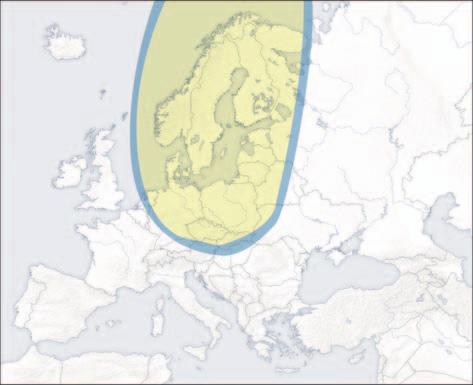
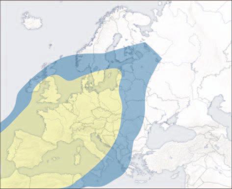
29 8. TIPS FOR CORRECT USAGE GLOMEX recommends observing the following indications for a correct use of the equipment. - The receiver must be activated before receiving the satellite programmes. - Keep the radome always mounted on the antenna. Its task is to protect all inner (fixed and moving) parts from wind, rain and dust. - Do not lean against and/or sit on the antenna! - Pay attention not to spill liquids of any kind into the antenna. - The radome should be cleaned periodically. Dust or dirt accumulated on the radome could affect the satellite signal receipt. Clean the radome with a cloth damped with water. DO NOT USE BRUSHES, ABRASIVE PRODUCTS, DETERGENTS OR ALCOHOL-BASED LIQ- UIDS. - Do not paint the surface of the radome! This would negatively affect signal receipt. - The antenna requires a clear view of the sky to receive satellite signals. Possible very common signal obstructions include masts of other boats, bridges, on-board equipment, etc. GLOMEX antennas also do not operate inside storage areas. GL00045 Fig Heavy rain or snow could temporarily interrupt signal receipt from the satellite. - The boat must be within the coverage area of the selected satellite to receive the desired signal. Please refer to the satellite coverage footprints on page 71. S WARNING Bad weather conditions affect the quality of the signal and reduce image quality! - At the end of its life, do not scatter the antenna or its components into the environment, but take advantage of specialized waste disposal agencies. Fig
30 8.1 FOOTPRINTS: SATELLITE TRANSMISSION AREAS Satellite television is one of the few means which allow receiving information in any part of the world within the coverage area of the satellite you wish to receive. The signal transmitted by the satellite generally has a wide coverage area, as shown in the purely indicative footprints on the following page, and thus guarantees you can watch the same TV programmes in various areas. However, it is important to remember that ground obstacles are the main causes of satellite antenna malfunction. Ground obstacles include all bodies which could be located between satellite and antenna, such as masts of other boats, bridges, on-board equipment, etc. The signal transmitted by the satellite is also affected by weather conditions (storm clouds or ice clouds). The footprints show the satellite coverage areas on the Earth by using the GLOMEX satellite antennas. S WARNING In case of bad weather, signals will be weaker; therefore, the image quality could be reduced, up to completely fading away. It is also very important to make sure, upon purchase, that the dimensions of the satellite antenna are the most appropriate ones to receive the signal in the areas where you spend your holiday. Footprints are indicative and referred to the satellite with the strongest E.I.R.P. (Equivalent Isotropic Radiated Power). 70


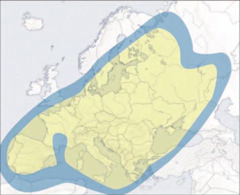
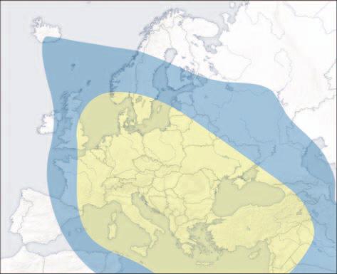
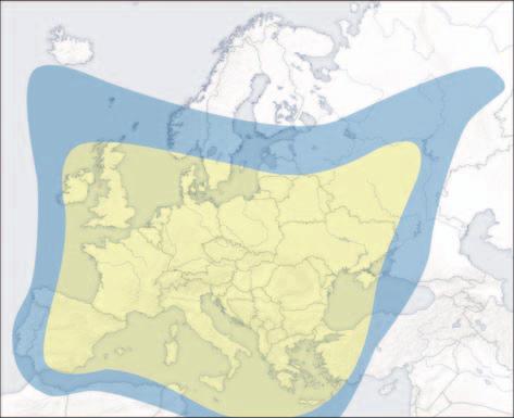
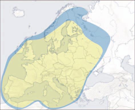
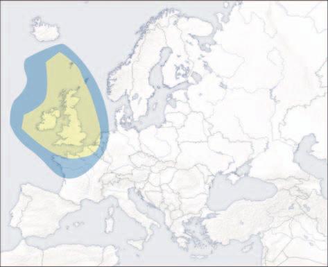
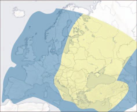
31 ATLANTIC BIRD 3 (5 W) Fig. 32 GL
32 9. MAINTENANCE 9.1 PREVENTIVE MAINTENANCE GLOMEX antennas require minimum preventive maintenance. Observing the following instructions is sufficient to maintain a high equipment performance. Monthly checks - Wash the radome surface with a cloth damped with fresh water; do not direct pressurized water jets onto the radome. S WARNING Do not use brushes, abrasive products, detergents or alcohol-based liquids. Should you have problems with the operation or in case you need technical support, first of all contact the authorized Retailer. Keep at hand the serial number of your antenna (on page 2 in this manual) and a list with the failure symptoms. Should no Retailer be available, contact the GLOMEX Service Centre (see section Technical Support ). S WARNING You will be asked the serial number of your antenna during any service or troubleshooting phone call. The serial number is found on page 2 of the user manual of your antenna (see page 44 for serial number indications). Yearly checks - Check the outer conditions of the radome. Clean from dust and dirt if necessary. Checks before any long cruise - Check that the antenna is correctly fastened. S DANGER Before carrying out any maintenance or cleaning operation, or after each use, ALWAYS turn off the antenna by means of the switch located on the control unit or from the on-board control panel. S WARNING Conserve the installation and user manual with care, as it contains the serial number of your antenna! 9.2 SPARE PARTS The following table lists the codes of the components which can be supplied as spare parts directly by the Retailer. Component Lower radome SATURN V9104S2U Upper radome SATURN V9104S2U Lower radome SATURN V9104SKEWS2U Upper radome SATURN V9104SKEWS2U Lower radome MARS V9804S2U Upper radome MARS V9804S2U Lower radome MARS V9804SKEWS2U Upper radome MARS V9804SKEWS2U Lower radome RHINE R9804S2U Upper radome RHINE R9804S2U Lower radome RHINE R9804SERS2U Upper radome RHINE R9804SERS2U GLOMEX code V9104S2U-LR V9104S2U-UR V9104SKEWS2U-LR V9104SKEWS2U-UR V9804S2U-LR V9804S2U-UR V9804SKEWS2U-LR V9804SKEWS2U-UR R9804S2U-LR R9804S2U-UR R9804SERS2U-LR R9804SERS2U-UR 72
33 9.3 SOFTWARE UPDATE BY FLASH USB The SD card must be inserted into the USB port located on the control unit front side. The USB memory used for updating must be formatted in FAT32, cluster size 4096 bytes (4k). It is therefore necessary to copy the provided file update-xxxxx.hex onto the USB memory, proceeding as follows: - Turn on the control unit and press the SAT SELECT button while BOOT is displayed. - Wait, the upgrade procedure takes about 30 seconds. - The message READY FOR UPDATE INSERT USB KEY will be displayed. - Once the upgrade is completed, UPGRADE SUCCESSFUL will be displayed. - Insert the USB flash formatted in FAT32 containing the file update-xxxxx.hex. - The control unit will check the integrity of the upgrade file displaying CHECK UPGRADE FILE. - Turn off the control unit and remove the USB memory. S WARNING In case of repeated failures in the software update procedure, please contact the GLOMEX Service Centre. NOTA: it is possible to download the necessary software updating file from the Glomex website () in section Technical Support - Download Area. 73
34 Flow chart USB UPGRADE TURN ON THE CONTROL UNIT PRESS SAT SELECT WHILE THE BOOT MESSAGE IS DISPLAYED INSERT USB MEMORY (ready for update insert usb key) CHECK UPGRADE FILE (check upgrade file) NO YES SOFTWARE UPGRADE (updating) CHECK THE UPGRADE FILE ON THE USB MEMORY TURN OFF THE CONTROL UNIT UPDATE COMPLETED (upgrade succesfull) NO YES Fig. 33 TURN OFF THE CONTROL UNIT AND REMOVE THE USB MEMORY 74
35 10. TROUBLESHOOTING When a malfunction of your satellite system occurs, it is very important to make a rapid check to understand the nature of the malfunction and, if possible, to find a remedy. To analyze a malfunction, it is appropriate to carry out the following verifications: - the malfunction has been generated through human mistake; - the malfunction is due to a weather problem; - the malfunction is due to a failure of the equipment itself or it is caused by an anomaly of another external appliance, but in some ways connected to the equipment; - in which phase the malfunction occurs: upon start-up, during normal operation, upon shutdown; - the malfunction is repeated; if so, according to what criteria; - what the malfunction determine from a functional point of view; 1. The control unit shows the error message ERR1 - whether the malfunction produces signals (light signals) and/or anomalous noise (such as hissing, buzzing, etc.) and/or anomalous odours (smell of burning) or not; - the malfunction interferes with the operation of other appliances; - the malfunction is an apparent failure (i.e. it disappears, for example, by turning off and then on again the equipment). The better you are able to answer the above-mentioned questions, the deeper the malfunction analysis will be. The following table analyzes the most probable causes which can lead to malfunctions of your GLOMEX satellite antenna. For any analyzed possible cause, a corrective measure is proposed, to efficiently solve, as much as possible, the trouble. Anomaly Cause Remedy - no connection between control unit and antenna 2. The antenna does not operate - wrong power supply cable connection - check that the connection cable between antenna and control unit is correctly fastened and is not interrupted or short-circuited - check the polarity on the power supply line - short-circuited coaxial cable - check the correct mounting of the coaxial cables - proper failure - contact the Service Centre - the coaxial cable has loosened or has disconnected from the antenna - check the connection of the coaxial cables - inner failure - contact the Service Centre 3. No status message on the - the satellite receiver is not - check the receiver connection decoder installed correctly - alternating current fluctuations - refer to the user manual of the receiver for support 4. No image on the TV - the receiver is off - turn off the control unit, turn on the receiver and then turn on the control unit again - the TV set is off or has not been tuned to AV - turn on the TV set and tune to AV channel - wrong cable connection on the receiver - the channel list is not up-todate - check that the SCART socket between the TV set and the receiver is installed correctly - carry out the automatic channel search in the receiver menu 75
36 5. Intermittent images for short periods 6. The equipment does not find the satellite - the satellite signals are obstructed by masts of other boats, bridges, on-board equipment, etc. - the boat is at the boundary of the coverage area - bad weather conditions - move the boat to allow an unobstructed view for the antenna - go back within the coverage area; refer to the footprints of the coverage areas on page 71 in this manual - wrong SKEW adjustment - adjust the SKEW by following - the satellite signals are obstructed by masts of other boats, bridges, on-board equipment, etc. - the boat is outside the signal coverage area the instructions on page 63 - move the boat to allow an unobstructed view for the antenna or correctly position the antenna on the boat - go back within the coverage area; refer to the footprints of the coverage areas on page 71 in this manual - the boat is heaving within the first 60 seconds after turning on the equipment - turn off the equipment for 10 seconds, turn it on again and make sure that the boat is still - bad weather conditions or moves in a straight line during the first 60 seconds after being turned on - inner failure - contact the Service Centre - the satellite signals are obstructed by masts of other boats, bridges, on-board equipment, etc. - the equipment software is not up to date - move the boat to allow an unobstructed view for the antenna - please contact the Service Centre to ask for software update - wrong SKEW adjustment - adjust the SKEW by following - parameters in satellite communication have changed the instructions on page 63 - please contact the Service Centre to ask for software update 7. Disturbed images - failure of the receiver - refer to the user manual of the receiver for support, spare parts and warranty conditions. 76
37 8. Confused, incomplete and obstructed images For further information, please address to the GLOMEX Service Centre (see section Technical Support ). - condensate or rain on the radome, which can disturb the signal - remove the condensate deposits from the radome with a fresh water jet (not under pressure) - bad weather conditions - periodically apply a liquid detergent suitable for dishes (no alcohol-based detergent) to the radome surface and let dry up - wrong SKEW adjustment - adjust the SKEW by following the instructions on page The decoder blocks - alternating current fluctuations - refer to the user manual of the receiver for support 10. The equipment operates with still boat but not with moving boat - the satellite signal is obstructed - failure in the gyroscope system - move away from possible obstacles obstructing the satellite signal - contact the Service Centre 11. RESHIPPING Should you need to return the antenna to GLOMEX, place it in a box, possibly the original one, making sure it is well packaged and that the upper and lower side are well recognizable. In order to prevent any damage to the antenna during transport, it is necessary to send it inside the original radome (upper and lower) and fasten it to the lower radome using 4 M8x10 screws. Together with the antenna, please also send the control unit, so that a verification of the whole system is possible. NOTA: GLOMEX will not be liable for possible damage occurred during transport due to incorrect packaging. S WARNING Do not ship the antenna to GLOMEX for repairs without having received a corresponding authorization to return the material (RMA), as reported in the general warranty/support conditions. 77
38 12. TECHNICAL SPECIFICATIONS SATURN4 V9104S2U Antenna dish diameter 47 cm Radome dimension 50 x 56 cm Antenna weight 13.0 kg Tracking rate 50 sec Antenna gain 35 db - 12 GHz PRIME FOCUS Dish type + HPD Polarization Linear (H + V) LNB 10.7 GHz / GHz Radome type UV resistant Power requirements 12/24 Vdc (1.5 A/h) Operating temperature range -20 C +55 C Azimuth turn range Unlimited Full elevation range 5-90 Type of stabilization Gyro on 2 axis +3 axis by interpolation Satellite identification NIT (Network identification table) Min. EIRP 49 dbw Future upgrade ready Yes 4 outputs to the Decoder output multiswitch (maximum 16 outputs) Autoskew NO Control unit 8 satellites loaded: see page 67 SATURN4 V9104SKEWS2U Antenna dish diameter 47 cm Radome dimension 50 x 56 cm Antenna weight 13.0 kg Tracking rate 50 sec Antenna gain 35 db - 12 GHz PRIME FOCUS Dish type + HPD Polarization Linear (H + V) LNB 10.7 GHz / GHz Radome type UV resistant Power requirements 12/24 Vdc (1.5 A/h) Operating temperature range -20 C +55 C Azimuth turn range Unlimited Full elevation range 5-90 Type of stabilization Gyro on 2 axis +3 axis by interpolation Satellite identification NIT (Network identification table) Min. EIRP 49 dbw Future upgrade ready Yes 4 outputs to the Decoder output multiswitch (maximum 16 outputs) Autoskew YES Control unit 8 satellites loaded: see page 67 78
39 MARS4 V9804S2U Antenna dish diameter 60 cm Radome dimension 66 x 66 cm Antenna weight 15.5 kg Tracking rate 50 sec Antenna gain 36.5 db - 12 GHz PRIME FOCUS Dish type + HPD Polarization Linear (H + V) LNB 10.7 GHz / GHz Radome type UV resistant Power requirements 12/24 Vdc (1.5 A/h) Operating temperature range -20 C +55 C Azimuth turn range Unlimited Full elevation range 5-90 Type of stabilization Gyro on 2 axis +3 axis by interpolation Satellite identification NIT (Network identification table) Min. EIRP 47 dbw Future upgrade ready Yes 4 outputs to the Decoder output multiswitch (maximum 16 outputs) Autoskew NO Control unit 8 satellites loaded: see page 67 MARS4 V9804SKEWS2U Antenna dish diameter 60 cm Radome dimension 66 x 66 cm Antenna weight 15.5 kg Tracking rate 50 sec Antenna gain 36.5 db - 12 GHz PRIME FOCUS Dish type + HPD Polarization Linear (H + V) LNB 10.7 GHz / GHz Radome type UV resistant Power requirements 12/24 Vdc (1.5 A/h) Operating temperature range -20 C +55 C Azimuth turn range Unlimited Full elevation range 5-90 Type of stabilization Gyro on 2 axis +3 axis by interpolation Satellite identification NIT (Network identification table) Min. EIRP 47 dbw Future upgrade ready Yes 4 outputs to the Decoder output multiswitch (maximum 16 outputs) Autoskew YES Control unit 8 satellites loaded: see page 67 79
40 RHINE R9804S2U Antenna dish diameter 60 cm Radome dimension 66 x 66 cm Antenna weight 15.5 kg Tracking rate 25 sec Antenna gain 36.5 db - 12 GHz PRIME FOCUS Dish type + HPD Polarization Linear (H + V) LNB 10.7 GHz / GHz Radome type UV resistant Power requirements 12/24 Vdc (1.5 A/h) Operating temperature range -20 C +55 C Azimuth turn range Unlimited Full elevation range 5-90 Type of stabilization Gyro on 2 axis +3 axis by interpolation Satellite identification NIT (Network identification table) Min. EIRP 47 dbw Future upgrade ready Yes 4 outputs to the Decoder output multiswitch (maximum 16 outputs) Autoskew NO Control unit 8 satellites loaded: see page 67 RHINE R9804SERS2U Antenna dish diameter 60 cm Radome dimension 66 x 66 cm Antenna weight 15.5 kg Tracking rate 25 sec Antenna gain 36.5 db - 12 GHz PRIME FOCUS Dish type + HPD Polarization Linear (H + V) LNB 10.7 GHz / GHz Radome type UV resistant Power requirements 12/24 Vdc (1.5 A/h) Operating temperature range -20 C +55 C Azimuth turn range Unlimited Full elevation range 5-90 Type of stabilization Gyro on 2 axis +3 axis by interpolation Satellite identification NIT (Network identification table) Min. EIRP 47 dbw Future upgrade ready Yes 4 outputs to the Decoder output multiswitch (maximum 16 outputs) Autoskew NO Control unit 8 satellites loaded: see page TECHNICAL SUPPORT In case technical support is needed, please contact the GLOMEX SERVICE CENTRE: Glomex Divisione Marine Via Faentina 165/G Ravenna (Italy) Tel (only from Italy) Fax service@glomex.it 80
SATFI UK User Manual Ver. 1.0 SATFI UK DP300. User Manual
 SATFI UK DP300 User Manual T able of contents 1 Introduction Specification..7 Antenna System Overview.8 Direct Broadcast Satellite Overview...9 System Components 10 2 Installation Unpacking the Unit.....12
Max-Dome Satellite System
 MXL007 (single LNB output) MXL007/TWIN (twin LNB output) Max-Dome Satellite System Installation & Operation Instruction Manual 9111407 issue 2 Useful Information Date of Purchase Retailer Installer Serial
USER MANUEL. SNIPE 2 Ref R13
 USER MANUEL SNIPE 2 Ref. 0141317R13 Contents 1. General Information 1-1. Introduction 1-2. Proper use and operation 1-3. Safety notes......... 2 3 3 2. Contents 2-1. Accessory included 2-2. Name of parts......
Fully ly Automaticti. Motorised Satellite t TV System. User s manual REV
 REV. 1.0 Fully ly Automaticti Motorised Satellite t TV System User s manual Customer Help Line: 1300 139 255 Support Email: support@satkingpromax.com.au Website: www.satkingpromax.com.au www.satkingpromax.com.au
Operating Instructions SAT-Finder plus
 GB Operating Instructions SAT-Finder plus Contents 1. Getting started 1.1 Package contents 1.2 Safety information 1.3 Connecting the SAT-Finder plus 1.4 Start-up process 2. Searching and finding 2.1. Automatic
Specifications. Compatible Receivers. Compatible Satellites. DIRECTV Sat DISH Sat DIRECTV Receiver Compatibility
 Quick Setup Make sure the Carryout G2 antenna is in a location with a clear view of the southern sky. Connect the provided coaxial cable from the primary receiver to the MAIN port on the base. Connect
Free Way 1M. In Motion Satellite Antenna. User Manual. Ver. 1.0
 Free Way 1M In Motion Satellite Antenna User Manual Ver. 1.0 Thanks to have bought our products. We recommend to read all this instructions manual before installing and making use of the l'antenna. Please,
UMN_ User Manual Antenna Simplex. TECHNO-MEDIA srl Via IV Novembre 92, Bollate (MB) tel
 tel") UMN_00094400 User Manual Antenna Simplex TECHNO-MEDIA srl Via IV Novembre 92, 20021 Bollate (MB) tel. 0248672988 - info@techno-media.it Aggiornamenti Revision N Date Owner Notes 1 02/03/2017 T-Media First
UMN_00094400 User Manual Antenna Simplex TECHNO-MEDIA srl Via IV Novembre 92, 20021 Bollate (MB) tel. 0248672988 - info@techno-media.it Aggiornamenti Revision N Date Owner Notes 1 02/03/2017 T-Media First
RV SATELLITE ANTENNA AUTOMATIC SKEW TWIN LNB SSA-850
 RV SATELLITE ANTENNA AUTOMATIC SKEW TWIN LNB SSA-850 INSTALLATION AND OPERATION MANUAL Please ensure that this manual is read in full prior to installing or using this sphere satellite unit. Design and
WINEGARD INSTALLATION MANUAL. Model GM Carryout Ladder Mount for mounting pipes with outer diameters between 1 to 1-1/8
 WINEGARD INSTALLATION MANUAL Model GM-3000 Carryout Ladder Mount for mounting pipes with outer diameters between 1 to 1-1/8 WARNING: DO NOT USE THE LADDER MOUNT AS A STEP! NOT INTENDED FOR USE WITH THE
TracVision R6DX Installation Guide
 TracVision R6DX Installation Guide These instructions explain how to install the TracVision R6DX satellite TV antenna system on an RV or motor coach. Complete instructions on how to use the system are
Instructions for Use P.154-UP (9/4) P.155-UP (9/8) P.150-UP-12 (9/12) P.150-UP-16 (9/16)
 P.155-UP (9/8) P.150-UP-12 (9/12) P.150-UP-16 (9/16)") Satellite multiswitch Instructions for Use P.154-UP (9/4) P.155-UP (9/8) P.150-UP-12 (9/12) P.150-UP-16 (9/16) EMP-CENTAURI is a registered trademark Dear Customer, Thank you for buying the EMP-Centauri
Satellite multiswitch Instructions for Use P.154-UP (9/4) P.155-UP (9/8) P.150-UP-12 (9/12) P.150-UP-16 (9/16) EMP-CENTAURI is a registered trademark Dear Customer, Thank you for buying the EMP-Centauri
Instructions for Use P.160-AP-8 (13/8) P.160-CP-8 (13/8) P.160-CP-12 (13/12) P.160-CP-16 (13/16)
 P.160-CP-8 (13/8) P.160-CP-12 (13/12) P.160-CP-16 (13/16)") Satellite multiswitch Instructions for Use P.160-AP-8 (13/8) P.160-CP-8 (13/8) P.160-AP-12 (13/12) P.160-CP-12 (13/12) P.160-AP-16 (13/16) P.160-CP-16 (13/16) EMP-CENTAURI is a registered trademark Dear
Satellite multiswitch Instructions for Use P.160-AP-8 (13/8) P.160-CP-8 (13/8) P.160-AP-12 (13/12) P.160-CP-12 (13/12) P.160-AP-16 (13/16) P.160-CP-16 (13/16) EMP-CENTAURI is a registered trademark Dear
INSTALLING THE MOUNT
 INSTALLING THE MOUNT Assemble the H-H Mount as the following diagram. Ensure the mounting tube indicates 0.If not. sit it to exactly 0 using the manual buttons on the bottom of the mount. The cable must
B2590/65SNZ. Crank-Up. Installation & Operation Instruction Manual NZ Iss 1
 B2590/65SNZ Crank-Up Installation & Operation Instruction Manual 9111410NZ Iss 1 Useful Information Date of Purchase Retailer Installer Serial Number Contents Warranty P3 Safety Precautions P4 Introduction
Contents. 1. General Information. 2. Contents. 3. Operating Instruction. 4. Program update. 5. Trouble Shooting. 6. Specifications
 Contents 1. General Information 1-1. Introduction 1-2. Proper use and operation 1-3. Safety Notes 2. Contents 2-1. Accessory Include 2-2. Name of parts 3. Operating Instruction 3-1. Connection Diagram
Fully ly Automaticti. Motorised Satellite t TV System. User s manual. ver 3.0.
 ver 3.0 Fully ly Automaticti Motorised Satellite t TV System User s manual Customer Help Line: 1300 139 255 Support Email: support@satkingpromax.com.au Website: www.satkingpromax.com.au www.satkingpromax.com.au
Field Service Procedure Replacement PCU Kit, Coastal
 1. Brief Summary: Troubleshooting document for diagnosing a fault with and replacing the PCU assembly on the coastal series antennas. 2. Checklist: Initialization Rate Sensor Outputs Run the Built In Test
USER MANUAL. Travel Vision R6
 www.travel-vision.com USER MANUAL Travel Vision R6 Version 1.0 February 2012 Introduction Congratulations on the purchase of your Travel Vision R6 system. This user manual provides all necessary information
Interactive Satellite Terminal Installation / Validation Manual
 Installation / Validation Manual Version October 5, 2016 Index INTERACTIVE SATELLITE TERMINAL 1. FCC COMPLIANCE... 3 2. TECHNICAL FEATURES...4 3. GENERAL DESCRIPTION...5 4. ELEMENTS CONTAINED IN THE TERMINAL...6
Chapter 4. Dish Antenna Installation. Installing a DISH 500 Antenna. Finding the Satellites
 These instructions guide you through the installation of a satellite system which includes your receiver (included with this manual), and a DISH Pro DISH 500 antenna system that can be identified by the
LCD Thermometer / Clock S No. 1253
 Installation and Operating Manual LCD Thermometer / Clock S No. 1253 The 3 fold thermometer with crystal clock is purpose build for the mounting in caravans, boats and intervention vehicles. Please read
Brillantes Fernsehen. Seaman. user manual. English. Seaman 37 Seaman 45 Seaman 60
 Brillantes Fernsehen Seaman user manual English Seaman 37 Seaman 45 Seaman 60 Table of contents Notes, Cautions, and Warnnings Introduction Specifications 6 Antenna System Overview 7 Direct Broadcast Satellite
Contents 1. Safety precautions... 1 Environment protection... 3 Features... 4 Operating notes... 4 Installation... 5
 Motor System for Satellite Receiver Model ID: MH1 EN User manual DE Bedienungsanleitung PL Instrukcja obsługi RU Руководство пользователя 6/2010 jp Contents 1. Safety precautions... 1 2. Environment protection...
In-Ceiling Electric Motorized Front Projection Screen Evanesce Series. User s Guide
 In-Ceiling Electric Motorized Front Projection Screen Evanesce Series User s Guide Important Safety & Warning Precautions Make sure to read this user s guide and follow the procedures below. Caution: The
Instruction Manual. Do not return antenna to place of purchase. Power Inserter. See page 2 for setup instructions
 Instruction Manual SD SD/HD SD/HD Do not return antenna to place of purchase Power Inserter See page 2 for setup instructions 2452360 Specifications Compatible with DIRECTV, DISH, & Bell TV programming
Digital satellite antenna with control panel. Kronings MobilSat +
 Digital satellite antenna with control panel User s Manual Models: MSP-S / MSP-C SUMMARY 1. Introduction... 2 1.1. Usage... 2 1.2. General notes... 3 1.3. The Control Panel... 3 2. Base functions... 4
Interactive Satellite Terminal Installation / Validation Manual
 Installation / Validation Manual Version September 14, 2017 Index INTERACTIVE SATELLITE TERMINAL 1. FCC COMPLIANCE... 3 2. TECHNICAL FEATURES...4 3. GENERAL DESCRIPTION...5 4. ELEMENTS CONTAINED IN THE
For receivers and programming, call
 Instruction Manual for DISH Users www.winegard.com/mobile For receivers and programming, call 1-866-609-9374 For up-to-date information on receiver compatibility and programming, visit www.winegard.com/receivers
USER MANUAL. Travel Vision R6
 www.travel-vision.com USER MANUAL Travel Vision R6 Version 1.1 September 2012 Introduction Congratulations on the purchase of your Travel Vision R6 system. This user manual provides all necessary information
Instruction Manual for DIRECTV Users
 Instruction Manual for DIRECTV Users www.winegard.com/mobile For receivers and programming, call 1-866-609-9374 For up-to-date information on receiver compatibility and programming, visit www.winegard.com/receivers
User Guide. Do not return antenna to place of purchase
 User Guide For help, email help@winegard.com or call 1-800-788-4417 For Receivers and Programming, call 1-866-609-9374 For up-to-date information on receiver compatibility and programming, visit www.winegard.com/receivers
TracVision R6DX Installation Guide
 TracVision R6DX Installation Guide TracVision R6DX Installation Guide KVH s Premier Satellite TV System for RVs These instructions explain how to install the TracVision R6DX on an RV or motor coach. Complete
User Manual. SCR Multiswitch Ref. 9744SKY, 9746SKY, 9748SKY
 User Manual SCR Multiswitch Ref. 9744SKY, 9746SKY, 9748SKY No part of this manual may be copied, reproduced, transmitted, transcribed or translated into any language without permission. Unitron reserves
T850 Day & Night Security Camera
 T850 Day & Night Security Camera For use with Swann 4500 DVR EN INSTRUCTION MANUAL MT850_091014E Swann 2014 Before you begin Introduction Congratulations on your purchase of this T850 Day & Night Security
DO NOT RETURN ANTENNA TO PLACE OF PURCHASE
 Instruction Manual www.winegard.com/pathway For receivers and programming, call 1-866-593-0348 For up-to-date information on receiver compatibility and programming, visit www.winegard.com/receivers For
Colour Explosion Proof Video Camera USER MANUAL VID-C
 Colour Explosion Proof Video Camera USER MANUAL VID-C Part Number: MAN-0036-00 Rev 4 Copyright 2002 Net Safety Monitoring Inc. Printed in Canada This manual is provided for informational purposes only.
INSTALLATION GUIDE FOR THE MOTOR
 INSTALLATION GUIDE FOR THE MOTOR Motor Horizon-Horizon ref 450907 MET542 This symbol indicates that the product must not be treated as household waste. The harmfull substances possibly contained in the
In-Motion Automatic Satellite System. Model V30
 In-Motion Automatic Satellite System with built-in DVB for positive satellite identification Model V30 Installation and Operating Instructions Satellite Solutions for Mobile Markets 11200 Hampshire Avenue
V/L V/H H/L H/H. Satellite - Input. Programmable Cascadable switch. with 32 User Bands with Terrestrial input & 1 Legacy port
 : 47-862MHz For default UB frequencies: Unicable II Multiswitch 32 User Bands with & 1 Legacy port Installation manual 1 2 Thank you for purchasing Inverto s advanced multiswitch and we are certain it
SIRIUS HOME ANTENNA USER GUIDE & WARRANTY
 SIRIUS HOME ANTENNA FOR USER GUIDE & WARRANTY Thank you for purchasing the Monster SIRIUS Home Antenna for SIRIUS Satellite Radio. Your new antenna lets you enjoy SIRIUS Satellite Radio in the comfort
In-Motion Automatic Satellite System. Model V30
 In-Motion Automatic Satellite System with built-in DVB for positive satellite identification Model V30 Installation and Operating Instructions Satellite Solutions for Mobile Markets 11200 Hampshire Avenue
Troubleshooting Guide
 Troubleshooting Guide 9760 Series 9762 Series Satellite Solutions for Mobile Markets 11200 Hampshire Avenue South, Bloomington, MN 55438-2453 Phone: (800) 982-9920 Fax: (952) 922-8424 www.kingcontrols.com
Electric Wall/Ceiling Projection Screen Saker Tab-Tension Series User s Guide
 Electric Wall/Ceiling Projection Screen Saker Tab-Tension Series User s Guide Important Safety & Warning Precautions Make sure to read this user s guide and follow the procedures below. Caution: The screen
Photovoltaic Module Installation Manual (IEC)
") Phono Solar Technology Co., Ltd. Add: No. 1 Xinghuo Rd., Nanjing Hi-tech Zone, Nanjing, China Tel: +86 25 5863 8000 Fax: +86 25 5863 8009 E-mail: support@phonosolar.com Website: www.phonosolar.com PHONO
Phono Solar Technology Co., Ltd. Add: No. 1 Xinghuo Rd., Nanjing Hi-tech Zone, Nanjing, China Tel: +86 25 5863 8000 Fax: +86 25 5863 8009 E-mail: support@phonosolar.com Website: www.phonosolar.com PHONO
Indoor/Outdoor Security System with Quad Monitor User s Manual
 Indoor/Outdoor Security System with Quad Monitor User s Manual 4919539 Important! Please read this booklet carefully before installing or using these units. WARNING - These units should ONLY be opened
Automatic Satellite System. Model KD5500
 Automatic Satellite System for DISH Network Programming Model KD5500 Installation and Operating Instructions Digital TV Solutions for Mobile Markets 11200 Hampshire Avenue South, Bloomington, MN 55438-2453
2.0 Wall Mount TV Soundbar Instruction Manual
 8010275 2.0 Wall Mount TV Soundbar Instruction Manual Read all of the instructions before using this soundbar and keep the manual in a safe place for future reference. Safety Information CA UT IO N RISK
EAGLE RE-1 CONTROLLER
 EAGLE RE-1 CONTROLLER For Use On ALL MotoSAT Mounts Supported Systems HD SL5 DirecTV HD DP3 Dish Network HD SC2 SHAW HD DP3 BELL TV EXECUTIVE 18" DirecTV 101 Dish Network 119 MSC-60 SHAW MD-500 Dish Network
Electric Wall/Ceiling Projection Screen Saker Series User s Guide
 Electric Wall/Ceiling Projection Screen Saker Series User s Guide Important Safety & Warning Precautions Make sure to read this user s guide and follow the procedures below. Caution: The screen s Black
15 Marine Satellite System. Model 1200-KU
 15 Marine Satellite System with built-in DVB for positive satellite identification Model 1200-KU Installation and Operating Instructions Satellite Solutions for Mobile Markets 11200 Hampshire Avenue South,
Photovoltaic Module Installation Manual (IEC)
") Phono Solar Technology Co., Ltd. Add: No. 1 Xinghuo Rd., Nanjing Hi-tech Zone, Nanjing, China Tel: +86 25 5863 8000 Fax: +86 25 5863 8009 E-mail: support@phonosolar.com Website: www.phonosolar.com PHONO
Phono Solar Technology Co., Ltd. Add: No. 1 Xinghuo Rd., Nanjing Hi-tech Zone, Nanjing, China Tel: +86 25 5863 8000 Fax: +86 25 5863 8009 E-mail: support@phonosolar.com Website: www.phonosolar.com PHONO
Electric Motorized Projection Screen Spectrum Series
 Electric Motorized Projection Screen Spectrum Series User s Guide 1 Important Safety & Warning Precautions Make sure to read this user s guide and follow the procedure below. Caution: The screen s Black
2 WIRE - LOOP POWERED TRANSMITTER FOR PT100 AND NI100 PROBES
 EN K20RTD 2 WIRE - LOOP POWERED TRANSMITTER FOR PT00 AND NI00 PROBES General Description The K20RTD instrument converts a temperature signal read by a PT00 (EN 60 75) or NI00 probe with connection by 2,
LWX-1. Satellite Weather Radio Module Installation Instructions A
 LWX-1 Satellite Weather Radio Module Installation Instructions 988-0158-13A Copyright 2009 Navico All rights reserved. No part of this manual may be copied, reproduced, republished, transmitted or distributed
INSTRUCTION & INSTALLATION GUIDE
 Digital electric radiator INSTRUCTION & INSTALLATION GUIDE 2 Introduction harmoni digital electric radiators are programmable with an exclusive electronic temperature programmer and manufactured with quality
MODEL... MXL012/55NZ MXL012/65NZ SIMPLICITY AT IT S BEST SET UP & USER MANUAL REGISTERED COMMUNITY DESIGN NO
 SIMPLICITY AT IT S BEST MODEL... MXL012/55NZ MXL012/65NZ SET UP & USER MANUAL REGISTERED COMMUNITY DESIGN NO.2207746. PATENT PENDING SIMPLICITY AT IT S BEST THANK YOU! For purchasing this product, we trust
Troubleshooting Guide 9630 Series
 Troubleshooting Guide 9630 Series Satellite Solutions for Mobile Markets 11200 Hampshire Avenue South, Bloomington, MN 55438-2453 Phone: (800) 982-9920 Fax: (952) 922-8424 www.kingcontrols.com 1305-SEMI
75 Elliptical Antenna System
 Instruction and Assembly Manual 75 Elliptical Antenna System 7291 NW 74th Street Miami, FL 33166 GlobeCast Technical Service: (888) 988-5288 Manufactured By: 2002 Channel Master LLC Printed in U.S.A. 8000915-02
DCL9AW. User Manual. English
 DCL9AW User Manual English PRECAUTIONS Information for users applicable in European Union countries 1 Information for users applicable in United States of America 1 Installation 1 Power connection 1 Maintenance
CHECK LINE. Model LS-36-LED. Stationary Stroboscope. Operating Manual BY ELECTROMATIC
 CHECK LINE BY ELECTROMATIC Stationary Stroboscope Model LS-36-LED Operating Manual Table of Contents 1.0 Introduction... 02 1.1 Unpacking 1.2 Optional Accessories 2.0 Safety Information... 3 3.0 Controls...
AWT150C/AWT150CS/ AWT151C CCD Camera
 AWT150C/AWT150CS/ AWT151C CCD Camera ISSUED OCTOBER 2018 WARNING Failure to follow all instructions and safety precautions in this manual, in the vehicle and body manufacturers' manuals and on the safety
GEOSATpro GS120. DiSEqC 1.2 Motorized H-H H Motor
 DiSEqC 1.2 Motorized H-H H Motor GEOSATpro GS120 Compatible with DiSEqC 1.2 & USALS Receivers Adjustable Hardware Limiters for 140 Degree Coverage Goto X Preprogrammed for North American Satellites LED
Owner s Manual. Sat-Meter MSK 15. Order No.:
 Owner s Manual Sat-Meter MSK 15 Order No.: 217 100 13 Thank you for choosing our latest and most innovative satellite meter. It has been designed and manufactured to a very high standard and offers a UNIQUE
Electric Wall/Ceiling Projection Screen Saker Plus Series User s Guide
 Electric Wall/Ceiling Projection Screen Saker Plus Series User s Guide Important Safety & Warning Precautions Make sure to read this user s guide and follow the procedures below. Caution: The screen s
Cellular Signal Booster
 Drive 4G-X Cellular Signal Booster THE ALUMINUM CASING OF YOUR SIGNAL BOOSTER!! WILL ADJUST TO THE TEMPERATURE OF ITS ENVIRONMENT, BUT IS DESIGNED TO PROTECT THE SIGNAL BOOSTER TECHNOLOGY. FOR EXAMPLE,
Omnidirectional TV/FM Antenna
 Omnidirectional TV/FM Antenna For Technical Services, email help@winegard.com or call 1-800-788-4417. DO NOT RETURN ANTENNA TO PLACE OF PURCHASE. DO NOT SNAP THE ANTENNA HEAD AND PEDESTAL TOGETHER PRIOR
Check our knowledge base at
 USER MANUAL Check our knowledge base at www.paralinx.net/support Copyright 2015 Paralinx LLC All Rights Reserved TABLE OF CONTENTS 1 Important Notice 10 LCD Screen 2 Safety Instructions 11 Indicators 3
TracVision R1DX. with Multi-service Interface Box/Controller. TracVision R1DX Installation Guide
 TracVision R1DX with Multi-service Interface Box/Controller TracVision R1DX Installation Guide TracVision R1DX Installation Guide Multi-service Interface Box/Controller Configuration These instructions
User Guide SiriUS ConneCt tuner
 User Guide Sirius ConneCt TUNER Congratulations on your purchase of the SIRIUS Connect SCH1P2 Satellite Radio Tuner! Your new SCH1P2 SIRIUS Connect Satellite Radio Tuner is designed to work with SIRIUS-Ready
Specifications. Dual Satellite Tracking Meter. With a built in 22Khz tone generator. Overview
 Dual Satellite Tracking Meter 38.8 With a built in Khz tone generator Specifications Power demand over 800 ma will result in an Over Current indication. Compatible With STARBAND Receivers Input Frequency:
Motor Operated Solar Shade with Valance Installation and Care Instructions Complete Video Instructions Available Online at
 * Motor Operated Solar Shade with Valance Installation and Care Instructions Complete Video Instructions Available Online at www.keystonefabrics.com Step 1: Identify the parts of your shade (parts shown
Field Service Procedure Replacement PCU Kit, ST24
 1. Brief Summary: Troubleshooting document for diagnosing a fault with and replacing the main PCU PCB on the ST24 antenna. 2. Checklist: Verify Initialization Built In Test 3. Theory of Operation: The
TRF STEP-DOWN TRANSFORMER USER MANUAL
 TRF STEP-DOWN TRANSFORMER USER MANUA www.ventilation-system.com 2013 ! WARNING The present operation manual consisting of the technical details, operating instructions and technical specification applies
PLL1920M LED LCD Monitor
 PLL1920M LED LCD Monitor USER'S GUIDE www.planar.com Content Operation Instructions...1 Safety Precautions...2 First Setup...3 Front View of the Product...4 Rear View of the Product...5 Installation...6
Spectra Batten (Order code: LEDJ95)
") www.prolight.co.uk Spectra Batten (Order code: LEDJ95) Safety WARNING FOR YOUR OWN SAFETY, PLEASE READ THIS USER MANUAL CAREFULLY BEFORE YOUR INITIAL START-UP! CAUTION! Keep this equipment away from rain,
www.prolight.co.uk Spectra Batten (Order code: LEDJ95) Safety WARNING FOR YOUR OWN SAFETY, PLEASE READ THIS USER MANUAL CAREFULLY BEFORE YOUR INITIAL START-UP! CAUTION! Keep this equipment away from rain,
Satellite B or D. Satellite Inputs (LNB Trunk)
") Power Diagnosis V/L Satellite A C V/H H/L Satellite Inputs (LNB Trunk) Satellite B D 2 x Wideband LNBs (SAT A/B or C/D) Universal Quattro LNB (SAT A/B/C/D) H/H Terrestrial input On DC in 19V 3.5A max.
Power Diagnosis V/L Satellite A C V/H H/L Satellite Inputs (LNB Trunk) Satellite B D 2 x Wideband LNBs (SAT A/B or C/D) Universal Quattro LNB (SAT A/B/C/D) H/H Terrestrial input On DC in 19V 3.5A max.
SNIPE Automatic Portable / Roof Top Satellite System
 SNIPE Automatic Portable / Roof Top Satellite System Our NEW SNIPE Automatic Portable Satellite System provides superb quality satellite television and radio to travelling Australians. SNIPE is designed
TracVision M1 Installation Guide. TracVision
 TracVision M1 with Multi-service Interface Box/Controller (Model M1dx DISH Network Configuration) (Model M1-C ExpressVu Configuration) Models M1d x / M1-C TracVision M1 Installation Guide TracVision M1
AVS50 USER GUIDE. 2.4GHz Audio/Video Sender System - AVS50
 2.4GHz Audio / Video Sender System AVS50 USER GUIDE 2.4GHz Audio/Video Sender System CONTENTS 1. Introduction... 2 2. Conformity of Use... 3 3. Controls and Connections... 4-5 4. Product Contents... 6
Digital satellite antenna with touch screen control panel Mounting instructions User Manual
 Digital satellite antenna with touch screen control panel Mounting instructions User Manual IMPORTANT To exercise the right of the 24 months warranty is mandatory that in the sales document is reported
WINEGARD. Operation Manual Made in the U.S.A. For up-to-date information on receiver compatibility and programming, visit
 WINEGARD Carryout Automatic Portable Satellite TV Antenna Operation Manual Made in the U.S.A. For up-to-date information on receiver compatibility and programming, visit www.winegard.com/receivers For
Website: Tel: ADDRESS: 6475 Las Positas Rd. Livermore, CA Item No. E5B/E5S Installation Guide
 Website: www.flexispot.com Tel: -855-4-808 ADDRESS: 6475 Las Positas Rd. Livermore, CA 9455 Item No. E5B/E5S Installation Guide Specifications Step Column 3 Max. Weight Capacity 0 Ibs (00 kg) Speed 38mm/s
GPS4000. GPS Time Receiver System. User Manual Version 1.1. World Time Solutions. World Time Solutions Limited
 GPS000 GPS Time Receiver System User Manual Version. World Time Solutions World Time Solutions Limited COPYRIGHT 0-0 World Time Solutions Limited. All Rights Reserved. All information contained within
TVAC20000 User manual
 TVAC20000 User manual Version 01/2010 Original English user manual. Keep for future use. 10 Introduction Dear Customer, Thank you for purchasing this product. This product meets the requirements of the
HDCVI Camera User s Manual
 HDCVI Camera User s Manual Version 1.0.2 Table of Contents 1 General Introduction... 1 1.1 Overview... 1 1.2 Features... 1 2 Device Framework... 2 3 Installation... 5 3.1 Installation for Model A... 5
TracVision 95W LNB Installation
 TracVision 95W LNB Installation To enable a TracVision system to receive DIRECTV international programming from the linear satellite located at 95W, a 95W LNB must be installed in a secondary M7SK or M9
USER MANUAL. WARNING Read the instructions before using the machine. EN (Original Instruction) / 1704
 / 1704") USER MANUAL European Models American Models 60/100/120 3/4/5 24/40/48 3/4/5 Read the instructions before using the machine. EN (Original Instruction) 9124097 / 1704 KEEP THIS USER MANUAL FOR FUTURE USE
USER MANUAL European Models American Models 60/100/120 3/4/5 24/40/48 3/4/5 Read the instructions before using the machine. EN (Original Instruction) 9124097 / 1704 KEEP THIS USER MANUAL FOR FUTURE USE
User Guide. Centrex Recording Interface
 User Guide Centrex Recording Interface Table of Contents Introduction... 2 The Meridian Business Set... 3 Key Numbering Plan (18 button add-on)... 4 Key Numbering Plan (36 button add-on)... 5 Key Numbering
Installation guide and user manual
 Installation guide and user manual GB TELECO WARRANTY Teleco guarantees its satellite dishes and terrestrial antennas against any material and/or construction fault and defect. The warranty offered by
Electric Motorized Projection Screen Spectrum Tab-Tension Series User s Guide
 Electric Motorized Projection Screen Spectrum Tab-Tension Series User s Guide Important Safety Precautions Make sure to read this user s guide and follow the procedures below prior to screen operation.
In-Line or 75 Ohm In-Line
 or 5 Ohm 1dB Adjustable Gain 800/1900 Smart Technology Contents: Quick Install Overview.... 2 Installation Diagram.... Understanding the Lights... 9 Warnings and Recommendations....11 Appearance of device
Horizon Nano-S2. DVB-S2 Signal Meter TEST REPORT
 TEST REPORT DVB-S2 Signal Meter Horizon Doesn t require its own power supply Extremely easy to use Displays signal level and quality Optimized for the measurement of four satellite positions Very fast
User Manual CVA3. HDMI Audio Decoder. All Rights Reserved. Version: CVA3_2016V1.0
 User Manual CVA3 All Rights Reserved Version: CVA3_2016V1.0 Preface Read this user manual carefully before using this product. Pictures shown in this manual is for reference only, different model and specifications
User Manual TP70L. HDBaseT Extender. All Rights Reserved. Version: TP70L2016V1.1
 User Manual TP70L HDBaseT Extender All Rights Reserved Version: TP70L2016V1.1 Preface Read this user manual carefully before using this product. Pictures shown in this manual is for reference only, different
ER-100 Eurorack 8 Channel Stereo, Transformer Balanced Out Summing Mixer User Manual
 ER-100 Eurorack 8 Channel Stereo, Transformer Balanced Out Summing Mixer User Manual Issue 0.1 SAFETY INSTRUCTIONS WARNING Always follow the precautions listed below to avoid any possibility of serious
DLP200M 2 Relay Module for Heating and Cooling Plants
 Product Sheet TH6.24 Thermostat Type DLP200M DLP200M 2 Relay Module for Heating and Cooling Plants The DLP 200 M is a relay module for activation of loads (namely thermal actuators or circulators) in wireless
Operating Instructions
 Operating Instructions SDI Input board Model No. AV-HS04M1 РУССКИЙ FRANÇAIS DEUTSCH ENGLISH ESPAÑOL ITALIANO Before operating this product, please read the instructions carefully and save this manual for
User Manual MODEL: KK1500-TR. Touch Display LCD Monitor. Installation Guide. 15 Resistive Touch LCD Monitor
 Touch Display LCD Monitor User Manual Installation Guide 15 Resistive Touch LCD Monitor MODEL: KK1500-TR i-tech Company LLC TOLL FREE: (888) 483-2418 EMAIL: info@itechlcd.com WEB: www.itechlcd.com User
HDCVI Camera User s Manual
 HDCVI Camera User s Manual Version 1.0.3 Table of Contents 1 General Introduction... 1 1.1 Overview... 1 1.2 Features... 1 2 Device Framework... 2 3 Installation... 5 Model A... 5 Model B1 and B2... 6