Brillantes Fernsehen. Seaman. user manual. English. Seaman 37 Seaman 45 Seaman 60
|
|
|
- Norah Howard
- 5 years ago
- Views:
Transcription


1 Brillantes Fernsehen Seaman user manual English Seaman 37 Seaman 45 Seaman 60
2 Table of contents Notes, Cautions, and Warnnings Introduction Specifications 6 Antenna System Overview 7 Direct Broadcast Satellite Overview 8 System Components 9 Installation Unpacking the Unit 11 Preparing for the installation 12 Selecting the location 13 Equipment and cable installation 14 Setting the LNB Skew Angle (Manual Skew version only) 15 Operation Receiving Satellite TV Signals 17 Turning the System On/Off 17 Changing Channels 18 Watching TV 18 Switching between Satellites 18 Operating the IDU 19 Troubleshooting Simple Check 24 Causes and Remedies 25 Caution Improper handling by unqualified personnel can cause serious damage to this equipment. Unqualified personnel who tamper with this equipment may be held liable for any resultant damage to the equipment. Install under DRY condition ONLY! Do not install this system in the rain, or under any wet conditions. Moisture may affect electronics and void warranty! Warning Sie benötigen 2 Personen, um die Antenne auf dem Dach zu installieren. Versuchen Sie nicht, die Antenne selbst zu installieren. Hinweis Bevor Sie beginnen, lesen Sie aufmerksam diese Bedienungsanleitung. Wenn Sie noch keine ähnlichen Arbeiten an vergleichbaren Geräten durchgeführt haben, versuchen Sie nicht, dieses Gerät selbst zu installieren. Appendix How to set the skew angle 26 Appendix B Satellite Coverage Map 31 Appendix C Firmware Upgrade 35 Megasat Werke GmbH Industriestraße 4a D Niederlauer info@megasat.tv 2 3
3 Figures Introduction Tables Table 1-1 Specification 7 Table 2-1 Parts included 12 Table A-1 Regional Skew Angle 32 Figures Figure 1-1 System Diagram 8 Figure 1-2 Satellite Blockage 9 Figure 1-3 System Components 10 Figure 2-1 Unpacking the Unit 12 Figure 2-2 Selecting the Location 15 Figure 2-3 Satellite Signals 17 Figure 2-4 Best Skew Angle 17 Figure 3-1 IDU LCD Screen 21 Figure 3-2 Appearance of IDU 22 Figure 3-3 Functions of LCD Display 22 Figure A-1 Europe Position Grid 31 Figure A-2 The Back of the Reflector 33 Figure A-3 LNB Skew Angle Adjustment 34 Figure B-1 Astra 2N Coverage Map 36 Figure B-2 Astra 2S Coverage Map 36 Figure B-3 Astra 1 Coverage Map 37 Figure B-4 Hotbird Coverage Map 37 Figure B-5 Sirius Coverage Map 37 Figure B-6 Thor Coverage Map 37 Figure B-7 Atlantic Bird 3 Coverage Map 38 Figure B-8 Hipasat Coverage Map 38 Figure C-1 SD Memory Card 40 Figure C-2 Formatting SD Memory Card 40 Figure C-3 The Back of IDU 41 Figure C-4 Writing Software 41 Figure C-5 Finishing to Write 41 The Seaman satellite antenna system is the innovative and a technologically advanced satellite In-Motion system. The Seaman has a unique combination of state-of-the art components with the most sophisticated satellite acquisition and tracking programs to provide the following features: Fast satellite acquisition Compatible with any Satellite Receiver Compatible with all Direct Broadcast Satellites (DBS) Built-in Digital Broadcast Receiver (DVB) Capable of High Definition receiving Specifications 7 Antenna System Overview 8 Direct Broadcast Satellite Overview 9 System Components

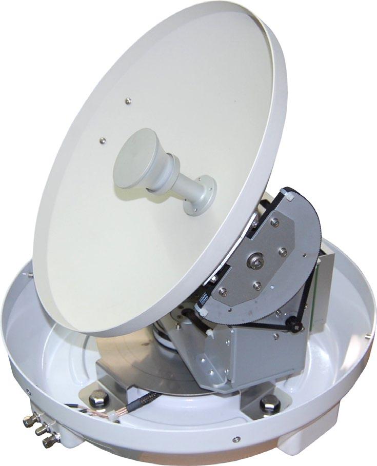
4 Specifications Antenna System Overview Antenna Type Parabola Frequency Band Ku Band Operating Frequency 11.7GHz to 12.75GHz Dish Dimension 320mm Radome Dimension 350x360mm Antenna Weight 6kg Antenna Gain 27dBi Minimum EIRP 51Dbw Polarization V/H or RHCP/LHCP Type of Stabilization 2-Axis Step Motor Elevation Range 5 to 90 Azimuth Range Unlimited Tracking Rate 50 /sec Temperate Range -20 to 70 Power 12~24VDC Auto Skew(Option) Range -90 to 90 A complete satellite TV system, illustrated in Figure 1-1, includes the Seaman antenna connected to a IDU, a satellite TV receiver, and a television set. antenna unit Power 12~24 V DC set-top-box indoor untit (IDU) television Table 1-1 Specification Figure 1-1 System Diagram 6 7

, and control elements within a radome.")
5 Direct Broadcast Satellite Overview System Components Direct Broadcast Service (DBS) satellites broadcast audio, video and data information from satellites located 22,000 miles in space. A receiving station, such as the Seaman antenna, should include a dish and satellite receiver to receive the signals and process them for use by the consumer audio and video equipment. The system requires a clear view of the satellite to maximize the signal reception. Blocked Antenna Unit The antenna unit houses the antenna positioning mechanism, LNB (low noise block), and control elements within a radome. Weathertight connectors join the power, signal, and control cabling from the belowdecks units. Objects such as tall lighthouse, bridges and big ship that block this view will cause a loss of signal. The signal will be quickly restored once the antenna has a clear line of sight again. Heavy rain, cloud, snow or ice may also interfere with the signal reception quality. If the satellite signal is lost due to blockage or severe weather condition, services from the receiver will be lost (picture will freeze frame and may disappear). When the satellite signal strength is again high enough, then the receiver will resume providing desired programming services. IDU (InDoor Unit) The IDU is the system s user interface, providing access to the system and its functions through an LCD and three buttons. The IDU also serves as the vessel s junction box, allowing the system to use vessel power, and supply and receive data to/from the antenna unit. Figure 1-2 Satellite Blockage Figure 1-3 System Components 8 9

 17 1. Open box and remove packing material. The following items are included in the packaging of the Seaman antenna.")
6 Installation Unpacking the unit This section offers a general explanation of how properly to install the Seaman antenna. Installation of the Seaman antenna must be accomplished by or under the supervision of an authorized dealer for the Limited Warranty to be valid and in force. The steps in the installation and setup process are as follows: Unpacking the Unit 12 Preparing for the installation 13 Selecting the location 14 Equipment and cable installation 16 Setting the LNB Skew Angle (Manual Skew version only) Open box and remove packing material. The following items are included in the packaging of the Seaman antenna. Item Description Quantity 1 Seaman Antenna Unit 1 each 2 IDU(InDoor Unit) 1 each 3 Power Cable 1 each 4 Coaxial Cable (10m) 1 each 5 Coaxial Cable (1m) 1 each 6 Installation & User Manual 1 set 2. Lift dome out of box vertically. Then lift unit out of box vertically. Do not turn box and roll out, or turn upside down to remove. Lift Unit straight up out of the carton! Figure 2-1 Unpacking the unit 10 11

7 Preparing for the installation Selecting the location Install Tools and Materials The Seaman antenna system is designed for simple installation and setup. However, the following list of equipment or items should be available during installation of the Seaman antenna. Electric drill and drill bits Socket wrench Silicon sealant Fastener suitable for specific application 1. Verification of the Vessel s Power Supply. Confirm that the vessel s power supply is 12VDC~24VDC. 2. Verification of the Satellite Receiver and IDU s attachment and the electricity supply Attach Satellite Receiver and IDU in the interior of the vessel or the trunk. Connect the power of Satellite Receiver and IDU. Once the power of Satellite Receiver and IDU is verified, it confirms that both Satellite Receiver and IDU are working normally. 3. Procedure of the satellite s attachment and installation. Attach the satellite on the flat surface area of the vessel s roof. Connect each end of the Coaxial antenna cable to the satellite s terminal and the IDU. Connect the IDU and the Satellite Receiver box together through the coaxial cable. Make sure that the satellite is working normally, once the power is supplied. Determine the optimum mounting location for the antenna radome assembly. It should be installed where: 1. The antenna has a clear line-of-sight view to as much of the sky as is practical. Choose a location where masts or other structures do not block the satellite signal from the dish as the vessel turns. 2. The antenna is at least 5 feet away from other transmitting antennas (HF, VHF and radar) that may generate signals that may interfere with the Seaman antenna. The further away the Seaman antenna is from these other antennas, the less impact their operation will have on it. 3. Direct radiation into the antenna from vessels radar, especially high power surveillance radar arrays, is minimized. The radome should be as far away from the vessels Radar as possible and should NOT be mounted on the same plane as the vessels Radar. 4. The antenna radome assembly should be rigidly mounted to the vessel. If necessary, reinforce the mounting area to assure that it does not flex due to the vessel motion or vibration. If these conditions cannot be entirely satisfied, the site selection will inevitably be a best compromise between the various considerations. Perform a through site inspection on the roof for the antenna to be mounted. 1. The antenna must have a clear view of the sky and the horizon at all the directions to avoid blockage of the satellite signal. 2. The antenna should be on the top of the vessel. Best Warnig! Turn off the power when attaching or detaching the antenna. Make sure that the attached satellite is fixed on the flat surface. When attaching, ensure that all the products are adhered properly. Ensure that all the cables are connected properly. Good Figure 2-2 Selecting the location Poor 12 13
8 Equipment and cable installation Setting the LNB skew angle This offers a general explanation of how to install the IDU and satellite receiver properly to the inside of vessel connecting with coaxial cable. 1. The Coaxial cable is routed from the antenna to the IDU inside the vessel. 2. After Once deciding where to place the IDU and satellite receiver, make sure that both units are placed in a dry and protected area. 3. The IDU and satellite receiver should be placed away from any heat source and in an area with proper ventilation. 4. Ensure that there are at least 3cm of space around both units for ventilation and connection of cables. Do not stack the units on top of each other. 5. The following describes the basic wiring configurations for the Seaman antenna system. Connect the Coaxial cable to the Seaman antenna port on the back of the IDU Connect one end of the supplied coaxial cable to the receiver port on the back of the IDU Connect the other end of the coaxial cable to the satellite receiver Figure 2-3 Satellite signals Signals transmitted in vertical(red) and horizontal(blue) wave offset exactly 90º from each other. Since linear satellite signals are oriented in a precise cross pattern, the Seaman antenna s receiving element, called an LNB (low-noise block) must be oriented in the same way to optimize reception. This orientation adjustment is referred to as the LNB s skew angle. Figure 1-4 illustrates how skew determines the amount of signal the LNB collects. The more signal, the better the reception. bad skew Good skew best skew The correct skew setting varies depending on your geographic location, since the orientation of your antenna to the satellite changes as you move. For complete details about adjusting the LNB s skew angle, see Appendix A How to Set the Skew Angle LNB signal collector satellite signal Figure 2-3 Satellite signals 14 15
9 Operation Receiving Satellite TV Signals The Seaman antenna system is easy to use. Under normal conditions, operation of the Seaman antenna requires no intervention from the user. Antenna unit initialization and satellite acquisition is completely automatic. Receiving Satellite TV Signals 20 Turning the System On/Off 20 Changing Channels 21 Watching TV 21 Switching between Satellites 21 Operating the IDU 22 Television satellites are located in fixed positions above the Earth s equator and beam TV signals down to certain regions of the planet. To receive TV signals from a satellite, you must be located within that satellite s unique coverage area. To check it, see Appendix B Satellite Coverage Map In addition, since TV satellites are located above the equator, the Seaman antenna must have a clear view of the sky to receive satellite TV signals. Anything that stands between the antenna and the satellite can block the signal, resulting in lost reception. Common causes of blockage include lighthouses, boat masts, trees, buildings, and bridges. Heavy rain, ice, or snow might also temporarily interrupt satellite signals. Turning the System On/Off Since power to the Seaman system is controlled by the IDU, you can turn the antenna on or off by applying/removing operating power to the IDU. Turning on the System Follow the steps below to turn on your Seaman System. 1. Make sure the antenna has a clear view of the sky. 2. Turn on your satellite TV receiver and TV. 3. Apply operating power to the IDU. 4. Wait one minute for system startup. The IDU will display the Tracking Satellite screen after system testing is complete. Turning off the System Follow the steps below to turn off your Seaman System. 1. Remove operating power from the IDU. 2. Turn off your satellite TV receiver and TV

10 Changing Channels Operating the IDU If you have followed the installation instructions, your system should be set to the satellite of your choice and the system should have downloaded the appropriate channel guides. When the Seaman antenna system and satellite receiver is properly configured, it is easy to change the channel using the remote control that normally comes with the receiver unit. Watching TV Appearance Power LCD Display The Seaman antenna is designed to operate as efficiently and as reliably as possible when the vessel is moved and anchored. It is also the quickest satellite acquisition system available among the Seaman antennas. If you have anchored the vessel and the antenna has completed to searching selected satellite, turn off IDU Power to avoid unnecessary use of power. Because the LNB receives its power from the Satellite Receiver through the IDU, the antenna will continue to receive the satellite TV signals. Satellite select button Sleep button Switching between Satellites You can switch between satellites using the IDU by pressing Satellite select buttons. Follow the steps below to switch to another satellite. 1. Ensure that the LCD screen of the IDU is displayed HOTBIRD ID: Figure 2-3 Satellite signals Functions of LCD Display It shows user selected satellite It shows current operational status It shows satellite id It shows intensity of signal 2. Press the Satellite select buttons to switch to another satellite. 3. The antenna shifts to track selected satellite. Wait for the Tracking Satellite screen to reappear with the ID of selected satellite displayed. Figure 3-3 Functions of LCD Display 18 19
11 Explanation of words in LCD INIT: It shows condition of initializing the antenna. INIT-SCH: It shows condition of initial search mode. SAT-MOVE: It shows condition of moving to another satellite. S:xxx: It shows intensity of signal. ID:xxx: It shows ID of acquired satellite. GYRO-CAL: It shows condition of calibrating the Gyro Sensor. General Operation Order HOTBIRD HOTBIRD It notice the start. The antenna is being initialized. ON Turn the power switch on. HOTBIRD Gyro sensor is being calibrated. Power HOTBIRD The antenna is searching the selected satellite. At first time, it can have longer time to find satellite. Once it can find satellite, next time it will have shorter time because it remember the elevation angle of satellite. Information of IDU LCD shows information of IDU. HOTBIRD ID: It shows ID and intensity of signal. The antenna is tracking the satellite. select satellite Push the Satellite select buttons to choose satellite. HOTBIRD ID: The Antenna stops to track the satellite
12 In case of search failure Troubleshooting HOTBIRD The antenna is searching the selected satellite. There are a number of common issues that can affect the signal quality or the operation of the Seaman antenna system. The following sections address these issues and potential solutions. HOTBIRD If the antenna cannot search the signal, it stops to search during 2 minutes and repeat searching the satellite. Simple Check 27 Causes and Remedies 28 Improper Wiring HOTBIRD The antenna is searching the selected satellite. If the system has been improperly wired, the antenna will not operate correctly. Refer to the User Manual for complete system wiring information or visit website HOTBIRD ID: It shows ID and intensity of signal. The antenna is tracking the satellite. Loose Cable Connectors We recommends periodically checking the antenna unit s cable connections. A loose cable connector can reduce signal quality or prevent automatic satellite switching using the receiver s remote control. Fasten the cable connector. HOTBIRD ID: The Antenna stops to track the satellite
13 Simple check Causes and Remedies Can the antenna see the satellite? The antenna requires an unobstructed view of the sky to receive satellite TV signals. Common causes of blockage include trees, buildings, bridges, and mountains. Is there excessive dirt or moisture on the antenna dome? Dirt buildup or moisture on the dome can reduce satellite reception. Clean the exterior of the dome periodically. Is it raining heavily? Heavy rain or snow can weaken satellite TV signals. Reception should improve once the inclement weather subsides. Is everything turned on and connected properly? Make sure your TV and receiver are both turned on and set up for the satellite input. Finally, check any connecting cables to ensure none have come loose. Is the antenna s LNB set to the correct skew angle? (Manual Skew Ver. Only) To optimize reception, the antenna s LNB needs to be set to the correct skew angle for the satellite you want to track. See Appendix A How to set the skew angle for details Receiver Fault Your satellite TV receiver might be set up incorrectly or defective. First check the receiver s configuration to ensure it is set up for the desired programming. In the case of a faulty receiver, refer to your selected receiver s user manual for service and warranty information. Satellite Coverage Issue Television satellites are located in fixed positions above the Earth s equator and beam TV signals down to certain regions of the planet (not worldwide). To receive TV signals from a satellite, you must be located within that satellite s unique coverage area. See Appendix-B Satellite Coverage Map Satellite Signal Blocked The Seaman Antenna needs a clear line of sight (LOS), view to the satellite for uninterrupted reception. Objects such as tall lighthouse, bridges and big ship that block this view will cause a loss of signal. The signal will be quickly restored once the antenna has a clear line of sight again. Heavy rain, cloud, snow or ice may also interfere with the signal reception quality. If the satellite signal is lost due to blockage or severe weather condition, services from the receiver will be lost (picture will freeze frame and may disappear). When the satellite signal strength is again high enough, then the receiver will resume providing desired programming services. Satellite Frequency Data Changed If some channels work, while one or more other channels do not, or if the antenna cannot find the selected satellite, the satellite s frequency data might have changed. You can visit any MEGASAT-authorized dealer or distributor for assistance or visit
 must be oriented in the same way to optimize reception.")
14 Appendix A European Position Grid How to Set up the Skew Signals transmitted in vertical and horizontal wave offset exactly 90º from each other. Since linear satellite signals are oriented in a precise cross pattern, the Seaman antenna s receiving element, called an LNB (low-noise block) must be oriented in the same way to optimize reception. This orientation adjustment is referred to as the LNB s skew angle. The correct skew setting varies depending on your geographic location, since the orientation of your antenna to the satellite changes as you move. This appendix provides how to set up the skew angle. If you wish to determine the Skew Angle(LNB), use the position grid(figure A-1 European Positon Grid) and table(tablea-1 Regional Skew angle) on page 32. Figure A-1 Europe Position Grid 26 27


15 If you wish to set the correct skew, see TableA-1 Regional Skew angle. The correct skew setting varies depending on your geographic location, since the orientation of your antenna to the satellite changes as you move. Setting the Skew Angle If you have determine the correct skew angle, follow the steps below to adjust the antenna s LNB skew angle. Caution To avoid bodily injury, be sure to turn off the antenna and disconnect power to all wored components. 1. Turn off the antenna and disconnect power to all wired components. 2. Using the screwdriver, remove the screws securing the radome. Then remove and set it aside in a safe place. 3. Locate the LNB assembly on the back of the antenna reflector. Reflector LNB Table A-1 Regional Skew Angle Figure A-2 The Back of the Reflector 28 29
16 4. Loosen the four screws fastening the LNB. 5. Adjust the LNB clockwise or counter-clockwise, until the skew arrow on the LNB points to the skew angle that you determined earlier. Appendix B Satellite Coverage Map Television satellites are located in fixed positions above the Earth s equator and beam TV signals down to certain regions of the planet (not worldwide). To receive TV signals from a satellite, you must be located within that satellite s unique coverage area. LNB (-) direction (+) direction Figure A-3 LNB Skew Angle Adjustment Caution Be sure to keep the LNB fully inserted into the hall to ensure the optimum performance. 6. Tighten the four screws. 7. Reinstall the radome

17 Satellite Coverage Map ASTRA 1 HOTBIRD Figure B-3 Astra 1 Coverage Map Figure B-4 Hotbird Coverage Map SIRIUS THOR 2/3 Figure B-5 Sirius Coverage Map Figure B-6 Thor 2/3 Coverage Map Satellite TV broadcast spot beams are aimed at land masses where the bulk of subscribers can be found. Thus, the signal strength decreases as you travel away from the land masses. The further you travel offshore you will require a larger size antenna. Although this information is believed to be correct, MEGASAT Technologies has no control over the variations on the actual satellite footprint coverage. Signal strength and reception can be affected by the weather conditions. ASTRA 2N ASTRA 2S Figure B-1 Astra 2N Coverage Map 32 Figure B-2 Astra 2S Coverage Map 33


18 Appendix C Atlantic Bird 3 Hispasat Firmware Update If satellite beam is changed or eliminated, you have to upgrade firmware of IDU. Your distributor provides the firmware. If antenna cannot search the selected satellite or move incorrectly, you need to change the firmware of IDU. To upgrade the firmware, follow the steps below. 1. Prepare the SD memory card. Figure C-1 SD memory card Figure B-7 Atlantic bird 3 Coverage Map Figure B-8 Astra 2S Coverage Map 2. Before you use the SD memory card, you should format it to FAT16(Default) Figure C-2 Formatting SD memory card 34 35

19 3. After formatting your SD card, copy the new software file. 4. Turn off the IDU. 5. Put your SD memory card into the SD slot of front side of the IDU. 6. Turn on the IDU. You can see the message WRITING SOFTWARE in LCD Display. WRITING Figure C-3 Writing software 7. If you see the message FINISH TO WRITE, IDU is finishing the software upgrade. You have to wait until the IDU is restarted. FINISH TO WRITE Figure C-4 Finishing to write 8. Turn off the IDU. Take your SD memory card away from the IDU. 9. Turn on the IDU

20 38 39

21 40 41

22 42 43
23 Brillantes Fernsehen Status: June 2012
SATFI UK User Manual Ver. 1.0 SATFI UK DP300. User Manual
 SATFI UK DP300 User Manual T able of contents 1 Introduction Specification..7 Antenna System Overview.8 Direct Broadcast Satellite Overview...9 System Components 10 2 Installation Unpacking the Unit.....12
Free Way 1M. In Motion Satellite Antenna. User Manual. Ver. 1.0
 Free Way 1M In Motion Satellite Antenna User Manual Ver. 1.0 Thanks to have bought our products. We recommend to read all this instructions manual before installing and making use of the l'antenna. Please,
OCEAN TV. Satellite Antennas. Ocean Series O60M Installation and User Manual Version 1.1. Ocean TV Ocean Series Antennas
 OCEAN TV Satellite Antennas Ocean Series O60M Installation and User Manual Version 1.1 www.oceantv.com.au Ocean TV 2010 OCEAN TV 1 www.oceantv.com.au Antenna System Overview A complete satellite TV system,
RV SATELLITE ANTENNA AUTOMATIC SKEW TWIN LNB SSA-850
 RV SATELLITE ANTENNA AUTOMATIC SKEW TWIN LNB SSA-850 INSTALLATION AND OPERATION MANUAL Please ensure that this manual is read in full prior to installing or using this sphere satellite unit. Design and
TracVision R6DX Installation Guide
 TracVision R6DX Installation Guide These instructions explain how to install the TracVision R6DX satellite TV antenna system on an RV or motor coach. Complete instructions on how to use the system are
Max-Dome Satellite System
 MXL007 (single LNB output) MXL007/TWIN (twin LNB output) Max-Dome Satellite System Installation & Operation Instruction Manual 9111407 issue 2 Useful Information Date of Purchase Retailer Installer Serial
TracVision R6DX Installation Guide
 TracVision R6DX Installation Guide TracVision R6DX Installation Guide KVH s Premier Satellite TV System for RVs These instructions explain how to install the TracVision R6DX on an RV or motor coach. Complete
TracVision M5/M7 Switchplate Configuration. TracVision M5/M7 User s Guide
 TracVision M5/M7 Switchplate Configuration TracVision M5/M7 User s Guide TracVision M5/M7 Switchplate Configuration User s Guide This user s guide provides all of the basic information you need to operate,
Interactive Satellite Terminal Installation / Validation Manual
 Installation / Validation Manual Version October 5, 2016 Index INTERACTIVE SATELLITE TERMINAL 1. FCC COMPLIANCE... 3 2. TECHNICAL FEATURES...4 3. GENERAL DESCRIPTION...5 4. ELEMENTS CONTAINED IN THE TERMINAL...6
TracVision M5/M7 Control Panel Configuration. TracVision M5/M7 User s Guide
 TracVision M5/M7 Control Panel Configuration TracVision M5/M7 User s Guide TracVision M7 with Auto Skew Important Information About Your System Important Information About Your TracVision M7 System with
TracVision M5/M7 User s Guide
 TracVision M5/M7 GyroTrac Configuration TracVision M5/M7 User s Guide TracVision M7 with Auto Skew Important Information About Your System Important Information About Your TracVision M7 System with Auto
WINEGARD. Movin View. Digital Satellite Mobile Antenna for Single Receiver for Use While Stationary or In-Motion Model MV-4005
 WINEGARD TM Movin View Digital Satellite Mobile Antenna for Single Receiver for Use While Stationary or In-Motion Model MV-4005 Made in the U.S.A. U.S. Patent Nos. 6,023,247; 6,188,300 Winegard Company
USER MANUEL. SNIPE 2 Ref R13
 USER MANUEL SNIPE 2 Ref. 0141317R13 Contents 1. General Information 1-1. Introduction 1-2. Proper use and operation 1-3. Safety notes......... 2 3 3 2. Contents 2-1. Accessory included 2-2. Name of parts......
Field Service Procedure Replacement PCU Kit, ST24
 1. Brief Summary: Troubleshooting document for diagnosing a fault with and replacing the main PCU PCB on the ST24 antenna. 2. Checklist: Verify Initialization Built In Test 3. Theory of Operation: The
Interactive Satellite Terminal Installation / Validation Manual
 Installation / Validation Manual Version September 14, 2017 Index INTERACTIVE SATELLITE TERMINAL 1. FCC COMPLIANCE... 3 2. TECHNICAL FEATURES...4 3. GENERAL DESCRIPTION...5 4. ELEMENTS CONTAINED IN THE
SNIPE Automatic Portable / Roof Top Satellite System
 SNIPE Automatic Portable / Roof Top Satellite System Our NEW SNIPE Automatic Portable Satellite System provides superb quality satellite television and radio to travelling Australians. SNIPE is designed
WINEGARD. Movin View. Digital Satellite Mobile Antenna for Two Receivers for Use While Stationary or In-Motion Model MV-4002
 WINEGARD TM Movin View Digital Satellite Mobile Antenna for Two Receivers for Use While Stationary or In-Motion Model MV-4002 Made in the U.S.A. U.S. Patent Nos. 6,023,247; 6,188,300 Winegard Company 3000
Field Service Procedure Replacement PCU Kit, Coastal
 1. Brief Summary: Troubleshooting document for diagnosing a fault with and replacing the PCU assembly on the coastal series antennas. 2. Checklist: Initialization Rate Sensor Outputs Run the Built In Test
TracVision R1DX. with Multi-service Interface Box/Controller. TracVision R1DX Installation Guide
 TracVision R1DX with Multi-service Interface Box/Controller TracVision R1DX Installation Guide TracVision R1DX Installation Guide Multi-service Interface Box/Controller Configuration These instructions
TracVision M1 Installation Guide. TracVision
 TracVision M1 with Multi-service Interface Box/Controller (Model M1dx DISH Network Configuration) (Model M1-C ExpressVu Configuration) Models M1d x / M1-C TracVision M1 Installation Guide TracVision M1
Automatic Satellite System. Model KD5500
 Automatic Satellite System for DISH Network Programming Model KD5500 Installation and Operating Instructions Digital TV Solutions for Mobile Markets 11200 Hampshire Avenue South, Bloomington, MN 55438-2453
TracVision. with Multi-service Interface Box/Controller. TracVision M1DX User s Guide
 TracVision M1DX with Multi-service Interface Box/Controller TracVision M1DX User s Guide TracVision M1DX Multi-service Interface Box/ Controller Configuration User s Guide This user s guide provides all
IMPORTANT! Special Instructions for the TracVision M3DX Conversion System ( )
") IMPORTANT! Special Instructions for the TracVision M3DX Conversion System (01-0279-05) You have purchased a special TracVision M3DX conversion system that can be configured for either circular or linear
IMPORTANT! Special Instructions for the TracVision M3DX Conversion System (01-0279-05) You have purchased a special TracVision M3DX conversion system that can be configured for either circular or linear
15 Marine Satellite System. Model 1200-KU
 15 Marine Satellite System with built-in DVB for positive satellite identification Model 1200-KU Installation and Operating Instructions Satellite Solutions for Mobile Markets 11200 Hampshire Avenue South,
TracVision M3 DX Version. Circular Configuration. TracVision M3 User s Guide
 TracVision M3 DX Version Circular Configuration TracVision M3 User s Guide TracVision M3DX Circular Configuration User s Guide This user s guide provides all of the basic information you need to operate,
MARINE AND FLUVIAL SATELLITE TV ANTENNAS WITH USB CONTROL UNIT SERIES MK3
 SATURN V9104S2U V9104SKEWS2U MARS V9804S2U V9804SKEWS2U RHINE R9804S2U R9804SERS2U MARINE AND FLUVIAL SATELLITE TV ANTENNAS WITH USB CONTROL UNIT SERIES MK3 USER AND INSTALLATION MANUAL 42 INDEX 1. FOREWORD...........................................................
LNB Conversion Instructions for TracVision C3/R5/R4
 LNB Conversion Instructions for TracVision C3/R5/R4 These instructions explain how to change between a circular (North American-type) LNB and a linear (European-type) LNB in a TracVision C3/R5/R4 system.
TracVision Interface Box Circular Configuration for North America. TracVision Interface Box User s Guide
 TracVision Interface Box Circular Configuration for North America TracVision Interface Box User s Guide TracVision Interface Box Circular Configuration for North America User s Guide This user s guide
Chapter 4. Dish Antenna Installation. Installing a DISH 500 Antenna. Finding the Satellites
 These instructions guide you through the installation of a satellite system which includes your receiver (included with this manual), and a DISH Pro DISH 500 antenna system that can be identified by the
TracVision M9 Standard Configuration. TracVision M9 User s Guide
 TracVision M9 Standard Configuration TracVision M9 User s Guide TracVision M9 Standard Configuration with Master Control Unit (MCU) User s Guide This user s guide provides all of the basic information
KD5500. Automatic Satellite TV Antenna for DISH Programming. Owner s Manual
 Automatic Satellite TV Antenna for DISH Programming KD5500 Owner s Manual 11200 Hampshire Avenue South, Bloomington, MN 55438 PH 952.922.6889 FAX 952.922.8424 kingcontrols.com IMPORTANT! The KING Relay
Fully ly Automaticti. Motorised Satellite t TV System. User s manual REV
 REV. 1.0 Fully ly Automaticti Motorised Satellite t TV System User s manual Customer Help Line: 1300 139 255 Support Email: support@satkingpromax.com.au Website: www.satkingpromax.com.au www.satkingpromax.com.au
TracVision R6 & Multi-service Interface Box. User s Guide
 TracVision R6 & Multi-service Interface Box User s Guide Welcome to TracVision R6 TracVision User s Guide R6 Satellite TV Antenna & Interface Box This manual provides detailed instructions on the proper
TracVision M5/M7. Configuration. GyroTrac. User s Guide
 TracVision M5/M7 GyroTrac Configuration User s Guide TracVision M5/M7 RF7 Board Addendum PLEASE READ! Important Addendum to the Product Manuals Your TracVision M5/M7 antenna is equipped with a new RF7
TracVision 95W LNB Installation
 TracVision 95W LNB Installation To enable a TracVision system to receive DIRECTV international programming from the linear satellite located at 95W, a 95W LNB must be installed in a secondary M7SK or M9
Contents. 1. General Information. 2. Contents. 3. Operating Instruction. 4. Program update. 5. Trouble Shooting. 6. Specifications
 Contents 1. General Information 1-1. Introduction 1-2. Proper use and operation 1-3. Safety Notes 2. Contents 2-1. Accessory Include 2-2. Name of parts 3. Operating Instruction 3-1. Connection Diagram
USER MANUAL. Travel Vision R6
 www.travel-vision.com USER MANUAL Travel Vision R6 Version 1.0 February 2012 Introduction Congratulations on the purchase of your Travel Vision R6 system. This user manual provides all necessary information
Welcome! Troubleshooting. Can the antenna see the satellite? Turning On the System. Single-Receiver Setup. Product Serial Number
 RC32 FORMAT PWR & TV POWER ON GUIDE OFF ACTIVE R LIST BACK EXIT MENU VOL INFO CHAN PAGE PREV 0 ENTER Welcome! Basic Operation ing Satellites Troubleshooting Congratulations! You have purchased the most
EAGLE RE-1 CONTROLLER
 EAGLE RE-1 CONTROLLER For Use On ALL MotoSAT Mounts Supported Systems HD SL5 DirecTV HD DP3 Dish Network HD SC2 SHAW HD DP3 BELL TV EXECUTIVE 18" DirecTV 101 Dish Network 119 MSC-60 SHAW MD-500 Dish Network
Satellite Television. A Guide to TracVision 6. user s guide. Operating Instructions. KVH TracVision 6
 A Guide to TracVision 6 user s guide Operating Instructions Satellite Television KVH TracVision 6 Welcome to TracVision 6 TracVision 6 User s Guide Congratulations on your choice of the TracVision 6, one
Reference WIRING THE SYSTEM TOGETHER. Page 4-1 TWO OR MORE RECEIVERS
 4 Reference WIRING THE SYSTEM TOGETHER TWO OR MORE RECEIVERS Each output on the LNBF can support a single receiver. You cannot connect two receivers to the same output (for example, by using a line splitter),
USER MANUAL. Travel Vision R6
 www.travel-vision.com USER MANUAL Travel Vision R6 Version 1.1 September 2012 Introduction Congratulations on the purchase of your Travel Vision R6 system. This user manual provides all necessary information
Fully ly Automaticti. Motorised Satellite t TV System. User s manual. ver 3.0.
 ver 3.0 Fully ly Automaticti Motorised Satellite t TV System User s manual Customer Help Line: 1300 139 255 Support Email: support@satkingpromax.com.au Website: www.satkingpromax.com.au www.satkingpromax.com.au
SATELLITE TV OPERATION / TECHNICAL MANUAL. Eagle II Controller
 SATELLITE TV OPERATION / TECHNICAL MANUAL Eagle II Controller 8 Nov 2017 2 Index Warnings... 4 Mount Definitions... 5 Controller Views... 6 Configuration and Software Versions... 8 Menus and Operations...
Electric Motorized Projection Screen PowerMax Tension Series
 Electric Motorized Projection Screen PowerMax Tension Series User s Guide Important Safety & Warning Precautions Make sure to read this user s guide and follow the procedures below. Caution: The screen
Operating Instructions SAT-Finder plus
 GB Operating Instructions SAT-Finder plus Contents 1. Getting started 1.1 Package contents 1.2 Safety information 1.3 Connecting the SAT-Finder plus 1.4 Start-up process 2. Searching and finding 2.1. Automatic
Troubleshooting Guide
 Troubleshooting Guide 9760 Series 9762 Series Satellite Solutions for Mobile Markets 11200 Hampshire Avenue South, Bloomington, MN 55438-2453 Phone: (800) 982-9920 Fax: (952) 922-8424 www.kingcontrols.com
In-Ceiling Electric Motorized Front Projection Screen Evanesce Series. User s Guide
 In-Ceiling Electric Motorized Front Projection Screen Evanesce Series User s Guide Important Safety & Warning Precautions Make sure to read this user s guide and follow the procedures below. Caution: The
SATELLITE TV OPERATION / TECHNICAL MANUAL. Eagle II Controller
 SATELLITE TV OPERATION / TECHNICAL MANUAL Eagle II Controller 10 May 2018 2 Index Warnings... 4 Mount Definitions... 5 Controller Views... 6 Configuration and Software Versions... 8 Menus and Operations...
Field Service Procedure Receive Path Troubleshooting
 1. Brief Summary: Troubleshooting document for diagnosing a fault with the receive path of an installation. 2. Checklist: Switch LNB Bands Connection Issue LNB Power Bands Switching Correctly 3. Theory
KOP4800 Owner s Manual
 KOP4800 Owner s Manual For use with Bell TV satellite programming IMPORTANT! The KING One Pro works with DIRECTV, DISH, and Bell TV. This manual is for Bell TV subscribers. Manuals for DISH and DIRECTV
Satellite Television. A Guide to TracVision G4. user s guide. Operating Instructions. KVH TracVision G4
 A Guide to TracVision G4 user s guide Operating Instructions Satellite Television KVH TracVision G4 Welcome to TracVision G4 TracVision G4 User s Guide Congratulations on your choice of the TracVision
Specifications. Compatible Receivers. Compatible Satellites. DIRECTV Sat DISH Sat DIRECTV Receiver Compatibility
 Quick Setup Make sure the Carryout G2 antenna is in a location with a clear view of the southern sky. Connect the provided coaxial cable from the primary receiver to the MAIN port on the base. Connect
1.8 METER SERIES 1183 Az/El MOUNT ANTENNA SYSTEM
 REVISION G January 11, 2002 ASSEMBLY MANUAL 1.8 METER SERIES 1183 Az/El MOUNT ANTENNA SYSTEM PRODELIN CORPORATION 1500 Prodelin Drive Newton NC 28658 1.8 METER SERIES 1183 Az/El MOUNT ANTENNA SYSTEM G
MITSUBISHI ELECTRONICS AMERICA, INC.
 User Experiences Problem During Operation Success User Resolves Problem Using Troubleshooting Instructions in Operating Manual No Success User Calls Dealer Success Dealer Resolves Problem Over Phone Using
Digital satellite antenna with control panel. Kronings MobilSat +
 Digital satellite antenna with control panel User s Manual Models: MSP-S / MSP-C SUMMARY 1. Introduction... 2 1.1. Usage... 2 1.2. General notes... 3 1.3. The Control Panel... 3 2. Base functions... 4
User Guide SiriUS ConneCt tuner
 User Guide Sirius ConneCt TUNER Congratulations on your purchase of the SIRIUS Connect SCH1P2 Satellite Radio Tuner! Your new SCH1P2 SIRIUS Connect Satellite Radio Tuner is designed to work with SIRIUS-Ready
Owner s Manual. Sat-Meter MSK 15. Order No.:
 Owner s Manual Sat-Meter MSK 15 Order No.: 217 100 13 Thank you for choosing our latest and most innovative satellite meter. It has been designed and manufactured to a very high standard and offers a UNIQUE
UMN_ User Manual Antenna Simplex. TECHNO-MEDIA srl Via IV Novembre 92, Bollate (MB) tel
 tel") UMN_00094400 User Manual Antenna Simplex TECHNO-MEDIA srl Via IV Novembre 92, 20021 Bollate (MB) tel. 0248672988 - info@techno-media.it Aggiornamenti Revision N Date Owner Notes 1 02/03/2017 T-Media First
UMN_00094400 User Manual Antenna Simplex TECHNO-MEDIA srl Via IV Novembre 92, 20021 Bollate (MB) tel. 0248672988 - info@techno-media.it Aggiornamenti Revision N Date Owner Notes 1 02/03/2017 T-Media First
INSTALLATION GUIDE FOR THE MOTOR
 INSTALLATION GUIDE FOR THE MOTOR Motor Horizon-Horizon ref 450907 MET542 This symbol indicates that the product must not be treated as household waste. The harmfull substances possibly contained in the
Field Service Procedure Replacement EL Motor Kit, ST24
 1. Brief Summary: Troubleshooting document for diagnosing a fault with and replacing the elevation motor and encoder on the ST24 antenna. 2. Checklist: Verify Initialization Run the Built In Test 3. Theory
TracVision M9 LNB Replacement Instructions
 TracVision M9 LNB Replacement Instructions These instructions explain how to replace an LNB with a new LNB of the same type in a TracVision M9. Installation Steps LNB Replacement Instructions 1. Remove
KOP4800 Owner s Manual
 KOP4800 Owner s Manual For use with DIRECTV satellite programming IMPORTANT! The KING One Pro works with DIRECTV, DISH, and Bell TV. This manual is for DIRECTV subscribers. Manuals for DISH and Bell subscribers
In-Motion Automatic Satellite System. Model V30
 In-Motion Automatic Satellite System with built-in DVB for positive satellite identification Model V30 Installation and Operating Instructions Satellite Solutions for Mobile Markets 11200 Hampshire Avenue
Sea Tel is one of the Cobham Group companies and one of the most wide spread and recognizable SatCom manufacturers.
 Mobile Satellite TV maritime systems Sea Tel is one of the Cobham Group companies and one of the most wide spread and recognizable SatCom manufacturers. SatCom International offers you all types of Sea
Electric Wall/Ceiling Projection Screen Saker Tab-Tension Series User s Guide
 Electric Wall/Ceiling Projection Screen Saker Tab-Tension Series User s Guide Important Safety & Warning Precautions Make sure to read this user s guide and follow the procedures below. Caution: The screen
USER MANUAL. 27 Full HD Widescreen LED Monitor L27ADS
 USER MANUAL 27 Full HD Widescreen LED Monitor L27ADS TABLE OF CONTENTS 1 Getting Started 2 Control Panel/ Back Panel 3 On Screen Display 4 Technical Specs 5 Care & Maintenance 6 Troubleshooting 7 Safety
DataSAT ACU-2 Controller Wiring Configuration - Operation
 DataSAT ACU-2 Controller Wiring Configuration - Operation This manual covers basic wiring, antenna controller configurations, and typical operation. For proper operation, wiring and configuration are very
In-Motion Automatic Satellite System. Model V30
 In-Motion Automatic Satellite System with built-in DVB for positive satellite identification Model V30 Installation and Operating Instructions Satellite Solutions for Mobile Markets 11200 Hampshire Avenue
Sea-King Fully Stabilized Marine Satellite System 9762-SW. Installation and Operating Instructions
 Sea-King Fully Stabilized Marine Satellite System 9762-SW Installation and Operating Instructions MEMBER TM Satellite Solutions for Mobile Markets 11200 Hampshire Avenue South, Bloomington, MN 55438-2453
Cellular Signal Booster
 Connect 4G-X Cellular Signal Booster !! IT IS VERY MPORTANT TO POWER YOUR SIGNAL BOOSTER US NG A SURGE PROTECTED AC POWER STRIP WITH AT LEAST A 1000 JOULE RATING. FAILURE TO DO THIS WILL VOID YOUR WARRANTY
Troubleshooting Guide 9630 Series
 Troubleshooting Guide 9630 Series Satellite Solutions for Mobile Markets 11200 Hampshire Avenue South, Bloomington, MN 55438-2453 Phone: (800) 982-9920 Fax: (952) 922-8424 www.kingcontrols.com 1305-SEMI
500+ channels. With the all-new KVH TracVision M-series, enjoy satellite TV wherever you operate!
 With the all-new KVH TracVision M-series, enjoy satellite TV wherever you operate! There s only one way to enjoy home theatre-quality television wherever you operate satellite TV; and for the captain who
EAGLE RE-1 CONTROLLER For Use On MotoSAT HD Mounts
 EAGLE RE-1 CONTROLLER For Use On MotoSAT HD Mounts Supported Systems HD SL5 DirecTV HD DP3 Dish Network HD SC2 SHAW HD DP3 BELL TV EXECUTIVE DirecTV 101 Dish Network 119 MSC-60 SHAW MD-500 Dish Network
Satellite Television. A Guide to TracVision LF/SF. owner s manual. Installation Instructions User s Guide Technical Manual. KVH TracVision LF/SF
 A Guide to TracVision LF/SF owner s manual Installation Instructions User s Guide Technical Manual KVH TracVision LF/SF Satellite Television TracVision LF/SF Owner s Manual Addendum (ECO # 6857) The following
WINEGARD TRAV LER Automatic Multi-Satellite TV Antenna
 WINEGARD TRAV LER Automatic Multi-Satellite TV Antenna Model SK-7002 MANUAL STA R CHOICE A SHAW Company 1 888 554-STAR SK-7002 Winegard Company 3000 Kirkwood St. Burlington, IA 52601-2000 319/754-0600
Portable In-Motion Automatic Satellite System. Model VQ3000
 Portable In-Motion Automatic Satellite System with built-in DVB for positive satellite identification Model VQ3000 Operating Instructions Satellite Solutions for Mobile Markets 11200 Hampshire Avenue South,
Satellite Dish Installation Manual (Ver. 2) 1
 1") Satellite Dish Installation Manual Provided by DiscoverNet, Inc. Satellite Dish Installation Manual (Ver. 2) 1 Table of Contents Section 1: Introduction Page 3 Section 2: Recommended Tools and Materials
Satellite Dish Installation Manual Provided by DiscoverNet, Inc. Satellite Dish Installation Manual (Ver. 2) 1 Table of Contents Section 1: Introduction Page 3 Section 2: Recommended Tools and Materials
Caution. Hanging the Screen:
 Installation Instructions for Laminar and Laminar XL Projection Screens Caution 1. Read Instructions through completely before proceeding; keep them for future reference. Follow these instructions carefully.
Field Service Procedure Replacement GACP Control Panel Kit, ST24
 1. Brief Summary: Troubleshooting document for diagnosing a fault with and replacing the Graphic Antenna Control Panel (GACP) for the ST24 antenna. 2. Checklist: Verify Power to the GACP Verify Communications
A Guide to TracVision G8. owner s manual. Guide to Operation Guide to Technical Information. KVH TracVision G8. TVG8_OM_BinderCover_9.
 A Guide to TracVision G8 owner s manual Guide to Operation Guide to Technical Information Television TVG8_OM_BinderCover_9.03 KVH TracVision G8 Satellite * * * Notes * Press any button to return. ** If
HE INSTRUCTION MANUAL
 Outdoor Antenna Kit Model Number: HE170351 INSTRUCTION MANUAL OUTDOOR ANTENNA KIT Warranty Details REGISTER YOUR PURCHASE AT www.aldi.com.au/en/about-aldi/product-registration/ TO KEEP UP-TO-DATE WITH
KVH Tri-Sat AutoSwitch Kit Installation and Operation Instructions for TracVision M3DX
 KVH Tri-Sat AutoSwitch Kit Installation and Operation Instructions for TracVision M3DX A The following instructions explain how to install and operate the Tri-Sat AutoSwitch Kit on a TracVision M3DX system.
2.4 METER SERIES 1250 ANTENNA SYSTEM
 June 1,2009 Revision B Assembly Manual 2.4 METER SERIES 1250 ANTENNA SYSTEM General Dynamics SATCOM Technologies 1500 Prodelin Drive Newton NC 28658 2.4 Meter 2 Piece Az/El Installation Instructions B
PLL1920M LED LCD Monitor
 PLL1920M LED LCD Monitor USER'S GUIDE www.planar.com Content Operation Instructions...1 Safety Precautions...2 First Setup...3 Front View of the Product...4 Rear View of the Product...5 Installation...6
75 Elliptical Antenna System
 Instruction and Assembly Manual 75 Elliptical Antenna System 7291 NW 74th Street Miami, FL 33166 GlobeCast Technical Service: (888) 988-5288 Manufactured By: 2002 Channel Master LLC Printed in U.S.A. 8000915-02
Personal Information Page
 Rev. 08.29.07 Personal Information Page Installing Dealer Name Date of Installation Day Month Year Type of System Executive MD500 MD1000.2 MHDTV MD5Slim MSD60 Freedom (not recommended) Serial Number of
Portable Automatic Satellite System. Model VQ2000
 Portable Automatic Satellite System with built-in DVB for positive satellite identification Model VQ2000 Operating Instructions Satellite Solutions for Mobile Markets 11200 Hampshire Avenue South, Bloomington,
Connevans.info. DeafEquipment.co.uk. This product may be purchased from Connevans Limited secure online store at
 Connevans.info Solutions to improve the quality of life Offering you choice Helping you choose This product may be purchased from Connevans Limited secure online store at www.deafequipment.co.uk DeafEquipment.co.uk
TV Lift System Model CL-65 Installation Instructions
 TV Lift System Model CL-65 Installation Instructions Contact: Support@Nexus21.com Toll Free: (866) 500-5438 Phone: (480) 951-6885 Fax: (480) 951-6879 Revised: 01/17/17 Below is a parts list describing
Intellian i6pe Serial Number
 Intellian i6pe Serial Number This serial number will be required for all troubleshooting or service calls made regarding this product. Notice All Right Reserved Intellian i6pe and Intellian are the registered
Electric Wall/Ceiling Projection Screen Saker Series User s Guide
 Electric Wall/Ceiling Projection Screen Saker Series User s Guide Important Safety & Warning Precautions Make sure to read this user s guide and follow the procedures below. Caution: The screen s Black
Mobile Satellite TV Antenna With FastFind Remote Operating Manual
 TM Mobile Satellite TV Antenna With FastFind Remote Operating Manual Made in the USA 1. INTRODUCTION and BACKGROUND... 3 2. COMPENT OVERVIEW and SPECIFICATIONS... 4 3. FCC USER S INFORMATION....5 4. OPERATION...6-7
DH551C/DH550C/DL550C Double Sided Display User Manual
 DH551C/DH550C/DL550C Double Sided Display User Manual Disclaimer BenQ Corporation makes no representations or warranties, either expressed or implied, with respect to the contents of this document. BenQ
Four-Way Antenna Signal Booster. User Manual
 User Manual RETAIN THIS MANUAL FOR FUTURE REFERENCE PLEASE READ THIS MANUAL CAREFULLY BEFORE USE Table of Contents INTRODUCTION... 1 INSTALLING THE FOUR-WAY ANTENNA SIGNAL BOOSTER... 2 Method 1... 2 Method
Register your product and get support at SDV5122/27. EN User manual
 Register your product and get support at www.philips.com/welcome SDV5122/27 User manual Contents 1 Important 4 Safety 4 Notice for USA 5 Notice for Canada 5 Recycling 6 English 2 Your SDV5122 7 Overview
Dealer Training Test. Winegard Dealer Training
 Dealer Training Test Winegard Dealer Training Test 105 General Information 1. Most RV wiring uses two types of coax cable, RG-59 and RG-6. Which type of coax cable should be used for satellite applications?
Installation Manual Wall Mounting
 Installation Manual Wall Mounting EN FR IT NL CZ PL DigiDish 33 DigiDish 45 Satman 33 Satman 45 Multytenne 45 EN FR IT Dear customer, thank you for purchasing one of the quality products produced by TechniSat.
Kramer Electronics, Ltd. USER MANUAL. Model: VS-33Vxl. 3x1 Video Switcher
 Kramer Electronics, Ltd. USER MANUAL Model: VS-33Vxl 3x1 Video Switcher Contents Contents 1 Introduction 1 2 Getting Started 1 2.1 Quick Start 1 3 Overview 3 3.1 Recommendations for Achieving the Best
Electric Motorized Projection Screen Spectrum Tab-Tension Series User s Guide
 Electric Motorized Projection Screen Spectrum Tab-Tension Series User s Guide Important Safety Precautions Make sure to read this user s guide and follow the procedures below prior to screen operation.