1. Introduction. 1.1 Graphics Areas. Modeling: building specification of shape and appearance properties that can be stored in computer
|
|
|
- Octavia Thompson
- 6 years ago
- Views:
Transcription
1 1. Introduction 1.1 Graphics Areas Modeling: building specification of shape and appearance properties that can be stored in computer Rendering: creation of shaded images from 3D computer models 2 Animation: to create an illusion of motion through sequences of images
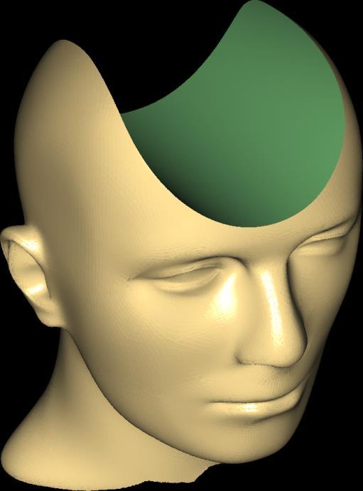
2 Modeling 3 For example, how should the pyramid on the right be represented internally? You need to record both geometric and topological Information: Vertex Table + Edge Table


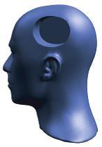
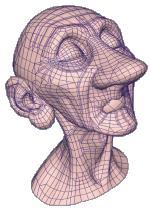
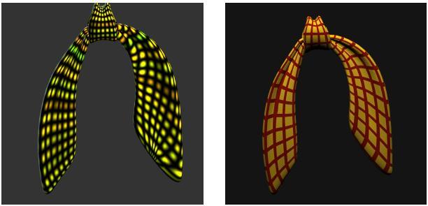
3 Modeling or, these? 4 shape design/representation using: implicit surfaces, parametric surfaces, subdivision surfaces,

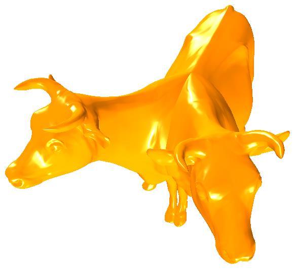
4 Modeling or, these? particle system 5


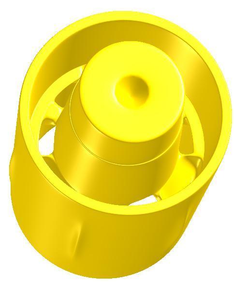
5 Modeling 6 Or, these? Context free grammer (fractals, L-system)

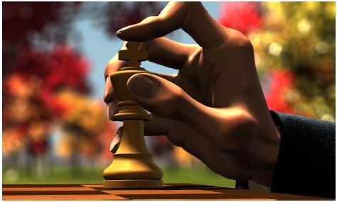
6 Rendering How should images like these be generated? 7


7 Rendering Or these? 8


8 Animation How should an illusion of motion be generated? 9


9 Animation Fat horse animation 10
10 Advantages Quantitative description - precise, not easy to be recognized Pictorial description - easy to be recognized 11
11 History Founded by the PhD thesis of Ivan D. Sutherland at MIT in 1963, - A line drawing system with data structures for storing symbol hierarchies and interaction techniques 12 SIGGRAPH: important CG organization, formed in 1969 Website:
12 Computer Graphics & Image Processing (blending together more each year) Image processing 13 Graphics Image Description Pattern recognition (computer vision)
13 1.2 Applications Art, Entertainment, and Publishing Movie production, Animation, and Special Effects Computer Games Browsing on the World Wide Web Slide, Book and Magazine Design 14
14 Examples 15
15 1.2 Applications 16 Process Control (Monitoring) Status display for refineries, power plants, computer networks from sensors attached to critical components Simulation - Flight simulation - Simulation of the movement of a robot - Simulation of virtual world

16 Virtual World 17
17 1.2 Applications Computer Aided Design (CAD) - Computer Aided Mechanical Part Design (big market) - Computer Aided Architectural Design - Electrical Circuit (IC) Design 18

18 Examples of CAD 19
19 1.2 Applications Scientific Analysis and Visualization Assist scientists in understanding measured data Provide insight into complex mathematical ideas 20
20 Bar chart Faculty PhD Students PhDs graduated Mit (1) Staford (2) CMU (3) Berkeley (4) Cornell (5)
21 1.3 Elements of Pictures Created in Computer Graphics Output Primitive: - polylines - text - filled regions - raster images 22

22 Examples 23
23 1.4 A Graphics System Key board Tablet Mouse Processor Memory Frame buffer monitor Output Device 24 Input Device
24 Output Devices (Video monitors) Cathode Ray Tube (CRT) Liquid Crystal Display (LCD) (Flat-panel display) 25
25 Video Monitor (CRT) Metallic coating Heating filament athode 26 Electron gun Control grid Focusing system (Electron lens) Deflection systems Vertical deflection Horizontal deflection Phospher coating Display surface
26 Video Monitor (CRT) Control-grid voltage: control the picture s intensity Focusing system: force the electrons to converge Deflection systems: to trace a picture on screen (most crucial part of the monitor) Phospher Coating: where image is created 27
27 Video Monitor (CRT) Electron gun Vertical deflection Metallic coating Heating filament athode Electrons 28 Negative voltage : : : : : : : : Control grid Focusing system (Electron lens) Horizontal deflection Phospher coating
28 Video Monitor (CRT) Electron gun Vertical deflection Metallic coating Heating filament athode Control grid Focusing system (Electron lens) Horizontal deflection Phospher coating Electron bean
29 Where is light from? 30 Phospher: when struck by electron beams, kinetic energy carried by the electrons is transferred to the electrons of the phospher atoms, so the electrons of the phospher atoms jump to a higher quantum energy levels. These excited electrons return to their previous quantum levels by giving up their extra energy in the form of light at frequency depicted by the quantum theory
30 Energy Light Start to release quantum energy in the form of light Quantum level Energy level is stable again, no light emitted after this point Stable level 31 persistence Time
31 Video Monitor (CRT) Electron gun Vertical deflection Metallic coating Ligh Heating filament athode Control grid Focusing system (Electron lens) Horizontal deflection Phospher coating Electron bean
32 Video Monitor (CRT) Electron gun Vertical deflection Metallic coating Light Heating filament athode Control grid Focusing system (Electron lens) Horizontal deflection Phospher coating Electron bean
33 Why is refresh necessary? Persistence: the time from the removal of excitation to the moment when phosphersense decayed to 10% of the initial light output Refresh rate: number of times per second a picture is redrawn (determined by persistence) 34 Fusion frequency: the refresh rate above which a picture stops flickering & fuses into a steady picture
34 Note Refresh rate for raster scan display is fixed (30 to 120), independent of the picture complexity Highly dynamic applications (such as computer games) need low-persistence phospher. CAD applications tend to use long-persistence phospher. The relationship between fusion frequency and persistence is nonlinear. 35
35 1.5 Display Processing Unit CPU Image Creation System Image Storage System Image Display System Display (Scan Conversion) (Frame Buffer) (Image Controller) 36
36 Display Processing Unit (a simple two-color raster scan system) Frame Buffer X-address Y-address 1 Pixel value Scan Controller Intensity Image Controller To Deflection Display Screen 37
37 Image Creation System Scan-converts abstract representation of an image into appropriate pixel values in the frame buffer 38
38 Scan Conversion (p, q) (r, s) (c, d) Frame Buffer (a, b) (Scan Conversion) 39
39 Image Storage System (frame buffer, bitmap) 40 refresh memory arranged as a 2D array; each entry corresponds to a screen pixel (i.e., dimension of the frame buffer is the same as the resolution of the screen) each entry is composed of a number of bits; brightness and/or color value of each pixel of the screen is stored in corresponding entry in frame buffer implemented with solid state RAM
40 Image Storage System (a simple two-color raster scan system) X-address Y-address Scan Controller To Deflection 1 Pixel value Intensity Display Screen Frame Buffer 41
41 Image Display System (video/image controller) cycle through frame buffer row by row, 60 or 120 times/sec memory reference addresses are generated in synchronism with the raster scan; contents of the memory are used to control monitor beam s intensity changes in frame buffer is done during the 1.3 millisecond flyback (or, vertical retrace) time interlaced raster scan (to produce a picture whose effective refresh rate is closer to 120 than to 60 Hz). 42
42 Image Display System (a simple two-color raster scan system) Frame Buffer X-address Y-address Pixel value Scan Controller Intensity Image Controller To Deflection 43
43 Image Display System (a simple two-color raster scan system) Frame Buffer X-address Y-address 1 Pixel value Scan Controller Intensity Image Controller To Deflection 44 First row, first pixel
44 Image Display System (a simple two-color raster scan system) Frame Buffer X-address Y-address 0 Pixel value Scan Controller Intensity Image Controller To Deflection 45 First row, second pixel
45 Image Display System (a simple two-color raster scan system) Frame Buffer X-address Y-address 1 Pixel value Scan Controller Intensity Image Controller To Deflection 46 First row, third pixel
46 Image Display System (a simple two-color raster scan system) Frame Buffer X-address Y-address 1 Pixel value Scan Controller Intensity Image Controller To Deflection 47 Second row, first pixel
47 Image Display System (a simple two-color raster scan system) Frame Buffer X-address Y-address 0 Pixel value Scan Controller Intensity Image Controller To Deflection 48 Last row, last pixel ( 1/ 60 sec)
48 Image Display System (a simple two-color raster scan system) Frame Buffer X-address Y-address. Pixel value Scan Controller Intensity Image Controller To Deflection 49 Fly back (to do the next refresh cycle) (1.3 millisecond; update frame buffer)
49 What if dimension of the frame buffer is different from resolution of the display surface? X-address Y-address? Pixel value Scan Controller Intensity To Deflection Frame Buffer Image Controller 50 Do a right-shift of the X- and the Y-registers before sending the indices to the Frame Buffer
50 What if dimension of the frame buffer is different from resolution of the display surface? X-address Y-address 1 Pixel value Scan Controller Intensity To Deflection After right-shift 51 First row, first pixel, of the screen
51 What if dimension of the frame buffer is different from resolution of the display surface? X-address Y-address 0 Pixel value Scan Controller Intensity To Deflection After right-shift 52 First row, third pixel, of the screen
52 What if dimension of the frame buffer is different from resolution of the display surface? X-address Y-address 0 Pixel value Scan Controller Intensity To Deflection After right-shift 53 First row, fourth pixel, of the screen
53 What if dimension of the frame buffer is different from resolution of the display surface? X-address Y-address 1 Pixel value Scan Controller Intensity To Deflection After right-shift 54 Second row, first pixel, of the screen
54 What if dimension of the frame buffer is different from resolution of the display surface? X-address Y-address 1 Pixel value Scan Controller Intensity To Deflection After right-shift 55 Second row, 2nd pixel, of the screen
55 What if dimension of the frame buffer is different from resolution of the display surface? X-address Y-address 0 Pixel value Scan Controller Intensity To Deflection After right-shift 56 Second row, 3rd pixel, of the screen
56 What if dimension of the frame buffer is different from resolution of the display surface? X-address Y-address 0 Pixel value Scan Controller Intensity To Deflection After right-shift 57 Second row, 4th pixel, of the screen
57 1.6 Shadow Mask Color Monitor Green gun Red gun Blue gun Screen Shadow mask Blue Red 58 Green
58 Shadow Mask Color Monitor 59 phospher dots (red, green, blue) are arranged in triangular pattern called triad (or, pixel) three electron guns are used A shadow mask, behind the view surface, is equipped so that each small hole for each triad (holes are aligned so that each electron gun excites its corresponding phospher dot) resolution of these monitors is limited - (high resolution: triads are on about.21mm centers) - (home TV: triads are on about.60mm centers)
59 1.7 Display with Lookup Table (LUT) X address (x0, y0) Y address 12 bits Scan Controller R G B To Deflection Frame Buffer LUT (x0, y0) 60 Shadow mask CRT CRT Screen
60 Display with Lookup Table (LUT) each number stored in frame buffer is an index (address) into a lookup table (color table or color map) Lookup table provides significant saving on memory while gives the ability to change colors from picture to picture 61
61 1.8 Flat-Panel Displays Liquid-crystal display (LCD) Active matrix panel (AMP) Plasma panel 62
62 Reflective Liquid-crystal display (LCD) View direction Reflective layer Horizontal polarizer Horizontal grid wires Liquidcrystal layer Vertical grid wires Vertical polarizer 63
63 Reflective Liquid-crystal display (LCD) 64 Reflective layer Horizontal polarizer Horizontal grid wires Liquidcrystal layer Vertical grid wires With polarizing effect Vertical polarizer
64 Reflective Liquid-crystal display (LCD) 65 Reflective layer Horizontal polarizer Horizontal grid wires Liquidcrystal layer Vertical grid wires With polarizing effect Vertical polarizer
65 Reflective Liquid-crystal display (LCD) nothing 66 Reflective layer Horizontal polarizer Horizontal grid wires Liquidcrystal layer Vertical grid wires Vertical polarizer Without polarizing effect
66 Reflective Liquid-crystal display (LCD) nothing 67 Reflective layer Horizontal polarizer Horizontal grid wires Liquidcrystal layer Vertical grid wires Vertical polarizer Without polarizing effect

67 Reflective Liquid-crystal display (LCD) Six layers (see the above figure) Liquid-crystal is made up of long crystalline molecules arranged in a spiral fashion Direction of polarization of polarized light passing through is rotated 90 degrees The crystals line up in the same direction when in an electric field, therefore no polarizing effect 68
68 Reflective Liquid-crystal display (LCD) In this case the light passing through the liquidcrystal layer will be absorbed by the rear polarizer, so the viewer sees a dark spot on the display 69 To create a dark spot at (x1, y1), use matrix addressing: applying a negative voltage V to the vertical grid wire x1 and a positive voltage +V to the horizontal grid wire y1 to create an electric field at (x1, y1). x1 y1
69 Reflective Liquid-crystal display (LCD) To display dots at (x1, y1) and (x2, y2), cannot simply apply negative voltage to x1 and x2 and positive voltage to y1 and y2: that would cause dots to appear at (x1, y1), (x1, y2), (x2, y1) and (x2, y2). We have to activate them one at a time. The display is refreshed one row at a time. 70
")
70 Transmissive LCD (single pixel) 71
71 Color Transmissive LCD (single pixel w/ rgb sub) 72
72 Transmissive Liquid-crystal display (LCD) Backlight source 73 Reflective layer Horizontal polarizer Horizontal grid wires Liquidcrystal layer Vertical grid wires With polarizing effect Vertical polarizer Bright spot
73 Transmissive Liquid-crystal display (LCD) nothing Backlight source 74 Reflective layer Horizontal polarizer Horizontal grid wires Liquidcrystal layer Vertical grid wires Vertical polarizer Without polarizing effect dark spot
74 Active Matrix Panel (TFT LCD) LCD panel with a thin-film transistor (TFT) at each grid point Transistor can hold the cell in "adjusted" state until changed The display need not be refreshed and is brighter 75
")
75 Color Transmissive LCD (single pixel w/ rgb sub) 76
76 Plasma Panel Similar to the center part of the previous figure Array of tiny neon bulbs Need not be refreshed 77
77 1.9 Input Devices Logical Classes of devices and techniques Logical Device Function Physical device 78 Keyboard Locator Input character string Alphnumeric keyboard Indicate a position and/or orientation Tablet, mouse, joystick Pick Select a displayed entity Light pen Choice Dial (Valuator) Select from a set of actions or choices Input an analog value (number) PFK, mouse Slidebar, potentiometer
78 Mouse most commonly used 79
79 Mouse most commonly used using mechanical detector or optical detector to measure motion mechanical mice measure distance by turning a ball (at the bottom) and consequently a pair of encoders. The encoders measure motion in two directions. old optical mice measure distance traveled by counting lines on a special pad 80
80 Mouse most commonly used modern surface-independent optical mice work by using an optoelectronic sensor (essentially, a tiny low-resolution video camera) to take successive images of the surface on which the mouse operates. the surface is lit at a grazing angle by a light emitting diode (LED). 81
81 Mouse most commonly used 82
82 Mouse most commonly used the purpose is for the texture of the surface to cast shadows on the surface itself, like the situation of a hilly terrain lit at sunset. images taken of the surface are then compared to determine how far the mouse has moved. the displacement information is then sent to the computer to update the location of the mouse cursor. 83
83 Mouse most commonly used a relative device, has no absolute origin, report only changes from their former position the application program can reposition the cursor anywhere on the screen 84
84 1.10 Input Modes Defined by the relationship between the measure process and the trigger Measure: what the device returns to the user program Trigger: a physical action on the device The display processing unit contains a number of registers (buffers). Once initialized, input devices store appropriate values in these registers 85
85 Image Display System (a simple two-color raster scan system) X-address Y-address Scan Controller To Grid wires 1 Pixel value Intensity 86 Frame Buffer Input device Input device Input device
86 Input modes Request mode: application program requests input from a device, the graphics user interface returns control and the measure of the device only after the user has triggered the device Used with only one device at a time Application program cannot provide dynamic feedback, because application program does not regain control until the trigger action occurs 87
87 Input modes Sample mode: a single device is sampled, and the measure of the device is immediately returned. No trigger is needed Sequence of user inputs might be lost in sampling Sequence of user events might be lost in sampling Well-suited for dynamic feedback from the application program 88
88 Input modes Event mode: when a device is triggered, the device measure with the identifier for the deivce is placed in an "event queue (but application program is not interrupted) Application program first enables all devices whose use is to be permitted Once enabled, a trigger action for any of them places an event report in an input queue, in order of occurrence 89
89 Input modes: event mode Events GUI Application Program Examine events, Call processing module Process event type 1 Process event type 2 Process event type more natural mode for systems with several independent processes and shared input devices - typical for a graphical user interface (GUI) and is supported by the library. - handles both hardware interrupts and software interrupts
90 1.11 Clients and Servers Primary motivation for the development of X Window System: "do graphics over a network In a world of distributed computing and networks, building blocks are entities called "server" Printer Server Client Client File Server Computer Server Client 91 (Server: remote machine supporting client workstations)
91 Clients and Servers However, for X Window System & OpenGL Server: device that displays the graphics (machine in front of the user) Client: device that does computation (whatever machine running the application) 92
 Display DPU Display file Input Devices")
92 Concept of X Server Then (Vector Display Device): Host (CPU) Display DPU Display file Input Devices 93
93 Concept of X Server Now Client X Protocol X Protocol File Server CPU Display device 94 Display file Input devices Server
94 End 95
Types of CRT Display Devices. DVST-Direct View Storage Tube
 Examples of Computer Graphics Devices: CRT, EGA(Enhanced Graphic Adapter)/CGA/VGA/SVGA monitors, plotters, data matrix, laser printers, Films, flat panel devices, Video Digitizers, scanners, LCD Panels,
PTIK UNNES. Lecture 02. Conceptual Model for Computer Graphics and Graphics Hardware Issues
 E3024031 KOMPUTER GRAFIK E3024032 PRAKTIK KOMPUTER GRAFIK PTIK UNNES Lecture 02 Conceptual Model for Computer Graphics and Graphics Hardware Issues 2014 Learning Objectives After carefully listening this
CMPE 466 COMPUTER GRAPHICS
 1 CMPE 466 COMPUTER GRAPHICS Chapter 2 Computer Graphics Hardware Instructor: D. Arifler Material based on - Computer Graphics with OpenGL, Fourth Edition by Donald Hearn, M. Pauline Baker, and Warren
Comp 410/510. Computer Graphics Spring Introduction to Graphics Systems
 Comp 410/510 Computer Graphics Spring 2018 Introduction to Graphics Systems Computer Graphics Computer graphics deals with all aspects of 'creating images with a computer - Hardware (PC with graphics card)
Computer Graphics : Unit - I
 Computer Graphics Unit 1 Introduction: Computer Graphics it is a set of tools to create, manipulate and interact with pictures. Data is visualized through geometric shapes, colors and textures. Video Display
2.2. VIDEO DISPLAY DEVICES
 Introduction to Computer Graphics (CS602) Lecture 02 Graphics Systems 2.1. Introduction of Graphics Systems With the massive development in the field of computer graphics a broad range of graphics hardware
Reading. 1. Displays and framebuffers. History. Modern graphics systems. Required
 Reading Required 1. Displays and s Angel, pp.19-31. Hearn & Baker, pp. 36-38, 154-157. OpenGL Programming Guide (available online): First four sections of chapter 2 First section of chapter 6 Optional
Introduction to Computer Graphics
 Introduction to Computer Graphics R. J. Renka Department of Computer Science & Engineering University of North Texas 01/16/2010 Introduction Computer Graphics is a subfield of computer science concerned
Display Technologies CMSC 435. Slides based on Dr. Luebke s slides
 Display Technologies CMSC 435 Slides based on Dr. Luebke s slides Recap: Transforms Basic 2D Transforms: Scaling, Shearing, Rotation, Reflection, Composition of 2D Transforms Basic 3D Transforms: Rotation,
Part 1: Introduction to Computer Graphics
 Part 1: Introduction to Computer Graphics 1. Define computer graphics? The branch of science and technology concerned with methods and techniques for converting data to or from visual presentation using
Overview of Graphics Systems
 CHAPTER - 2 Overview of Graphics Systems Video Display Devices Instructions are stored in a display memory display file display list Modes: immediate each element is processed and displayed retained objects
Part 1: Introduction to computer graphics 1. Describe Each of the following: a. Computer Graphics. b. Computer Graphics API. c. CG s can be used in
 Part 1: Introduction to computer graphics 1. Describe Each of the following: a. Computer Graphics. b. Computer Graphics API. c. CG s can be used in solving Problems. d. Graphics Pipeline. e. Video Memory.
Displays. History. Cathode ray tubes (CRTs) Modern graphics systems. CSE 457, Autumn 2003 Graphics. » Whirlwind Computer - MIT, 1950
 Modern graphics systems. CSE 457, Autumn 2003 Graphics. » Whirlwind Computer - MIT, 1950") History Displays CSE 457, Autumn 2003 Graphics http://www.cs.washington.edu/education/courses/457/03au/» Whirlwind Computer - MIT, 1950 CRT display» SAGE air-defense system - middle 1950 s Whirlwind II
History Displays CSE 457, Autumn 2003 Graphics http://www.cs.washington.edu/education/courses/457/03au/» Whirlwind Computer - MIT, 1950 CRT display» SAGE air-defense system - middle 1950 s Whirlwind II
3. Displays and framebuffers
 3. Displays and framebuffers 1 Reading Required Angel, pp.19-31. Hearn & Baker, pp. 36-38, 154-157. Optional Foley et al., sections 1.5, 4.2-4.5 I.E. Sutherland. Sketchpad: a man-machine graphics communication
MODULE I MCA COMPUTER GRAPHICS ADMN APPLICATIONS OF COMPUTER GRAPHICS
 MODULE 1 1. APPLICATIONS OF COMPUTER GRAPHICS Computer graphics is used in a lot of areas such as science, engineering, medicine, business, industry, government, art, entertainment, advertising, education
Computer Graphics: Overview of Graphics Systems
 Computer Graphics: Overview of Graphics Systems By: A. H. Abdul Hafez Abdul.hafez@hku.edu.tr, 1 Outlines 1. Video Display Devices 2. Flat-panel displays 3. Video controller and Raster-Scan System 4. Coordinate
Reading. Displays and framebuffers. Modern graphics systems. History. Required. Angel, section 1.2, chapter 2 through 2.5. Related
 Reading Required Angel, section 1.2, chapter 2 through 2.5 Related Displays and framebuffers Hearn & Baker, Chapter 2, Overview of Graphics Systems OpenGL Programming Guide (the red book ): First four
CS 4451A: Computer Graphics. Why Computer Graphics?
 CS 445A: Computer Graphics z CCB, TT 9:3- Why Computer Graphics? z Fun! z Lots of uses: y Art, entertainment y Visualizing complex data/ideas y Concise representation of actions/commands/state y Design/task
Reading. Display Devices. Light Gathering. The human retina
 Reading Hear & Baker, Computer graphics (2 nd edition), Chapter 2: Video Display Devices, p. 36-48, Prentice Hall Display Devices Optional.E. Sutherland. Sketchpad: a man-machine graphics communication
Display Devices & its Interfacing
 Display Devices & its Interfacing 3 Display systems are available in various technologies such as i) Cathode ray tubes (CRTs), ii) Liquid crystal displays (LCDs), iii) Plasma displays, and iv) Light emitting
Computer Graphics NV1 (1DT383) Computer Graphics (1TT180) Cary Laxer, Ph.D. Visiting Lecturer
 Computer Graphics (1TT180) Cary Laxer, Ph.D. Visiting Lecturer") Computer Graphics NV1 (1DT383) Computer Graphics (1TT180) Cary Laxer, Ph.D. Visiting Lecturer Today s class Introductions Graphics system overview Thursday, October 25, 2007 Computer Graphics - Class 1
Computer Graphics NV1 (1DT383) Computer Graphics (1TT180) Cary Laxer, Ph.D. Visiting Lecturer Today s class Introductions Graphics system overview Thursday, October 25, 2007 Computer Graphics - Class 1
Downloads from: https://ravishbegusarai.wordpress.com/download_books/
 1. The graphics can be a. Drawing b. Photograph, movies c. Simulation 11. Vector graphics is composed of a. Pixels b. Paths c. Palette 2. Computer graphics was first used by a. William fetter in 1960 b.
Computer Graphics Prof. Sukhendu Das Dept. of Computer Science and Engineering Indian Institute of Technology, Madras Lecture - 5 CRT Display Devices
 Computer Graphics Prof. Sukhendu Das Dept. of Computer Science and Engineering Indian Institute of Technology, Madras Lecture - 5 CRT Display Devices Hello everybody, welcome back to the lecture on Computer
UNIT 1 INTRODUCTION TO COMPUTER
 UNIT 1 INTRODUCTION TO COMPUTER Introduction to Computer Structure 1.1 Introduction Objectives 1.2 Display Devices 1.2.1 Cathode Ray Tube Technology (CRT) 1.2.2 Random Scan Display 1.2.3 Raster Scan Display
Display Systems. Viewing Images Rochester Institute of Technology
 Display Systems Viewing Images 1999 Rochester Institute of Technology In This Section... We will explore how display systems work. Cathode Ray Tube Television Computer Monitor Flat Panel Display Liquid
Monitor and Display Adapters UNIT 4
 Monitor and Display Adapters UNIT 4 TOPIC TO BE COVERED: 4.1: video Basics(CRT Parameters) 4.2: VGA monitors 4.3: Digital Display Technology- Thin Film Displays, Liquid Crystal Displays, Plasma Displays
Computer Graphics. Introduction
 Computer Graphics Introduction Introduction Computer Graphics : It involves display manipulation and storage of pictures and experimental data for proper visualization using a computer. Typically graphics
Objectives: Topics covered: Basic terminology Important Definitions Display Processor Raster and Vector Graphics Coordinate Systems Graphics Standards
 MODULE - 1 e-pg Pathshala Subject: Computer Science Paper: Computer Graphics and Visualization Module: Introduction to Computer Graphics Module No: CS/CGV/1 Quadrant 1 e-text Objectives: To get introduced
These are used for producing a narrow and sharply focus beam of electrons.
 CATHOD RAY TUBE (CRT) A CRT is an electronic tube designed to display electrical data. The basic CRT consists of four major components. 1. Electron Gun 2. Focussing & Accelerating Anodes 3. Horizontal
decodes it along with the normal intensity signal, to determine how to modulate the three colour beams.
 Television Television as we know it today has hardly changed much since the 1950 s. Of course there have been improvements in stereo sound and closed captioning and better receivers for example but compared
CS2401-COMPUTER GRAPHICS QUESTION BANK
 SRI VENKATESWARA COLLEGE OF ENGINEERING AND TECHNOLOGY THIRUPACHUR. CS2401-COMPUTER GRAPHICS QUESTION BANK UNIT-1-2D PRIMITIVES PART-A 1. Define Persistence Persistence is defined as the time it takes
Screens; media that use additive primaries
 Image display Display is the final stage in the image processing pipeline: Continuous scenes are acquired and digitally processed. The display process essentially converts the discrete image back to continuous
Computer Graphics. Raster Scan Display System, Rasterization, Refresh Rate, Video Basics and Scan Conversion
 Computer Graphics Raster Scan Display System, Rasterization, Refresh Rate, Video Basics and Scan Conversion 2 Refresh and Raster Scan Display System Used in Television Screens. Refresh CRT is point plotting
Computer Graphics Hardware
 Computer Graphics Hardware Kenneth H. Carpenter Department of Electrical and Computer Engineering Kansas State University January 26, 2001 - February 5, 2004 1 The CRT display The most commonly used type
High-resolution screens have become a mainstay on modern smartphones. Initial. Displays 3.1 LCD
 3 Displays Figure 3.1. The University of Texas at Austin s Stallion Tiled Display, made up of 75 Dell 3007WPF LCDs with a total resolution of 307 megapixels (38400 8000 pixels) High-resolution screens
Displays and framebuffers
 Reading Optional Displays and framebuffers Brian Curless CSE 557 Autumn 2017 OpenGL Programming Guide (the red book available online): First four sections of chapter 2 First section of chapter 6 Foley
B. TECH. VI SEM. I MID TERM EXAMINATION 2018
 B. TECH. VI SEM. I MID TERM EXAMINATION 2018 BRANCH : COMPUTER SCIENCE ENGINEERING ( CSE ) SUBJECT : 6CS4A COMPUTER GRAPHICS & MULTIMEDIA TECHNIQUES Q 1. Write down mid point ellipse drawing algorithm.
L14 - Video. L14: Spring 2005 Introductory Digital Systems Laboratory
 L14 - Video Slides 2-10 courtesy of Tayo Akinwande Take the graduate course, 6.973 consult Prof. Akinwande Some modifications of these slides by D. E. Troxel 1 How Do Displays Work? Electronic display
Chapter 3. Display Devices and Interfacing
 Chapter 3 Display Devices and Interfacing Monitor Details Collection of dots Matrix of dots creates character Monochrome monitor screen is collection of 350 *720 350 rows and each rows having 720 dots
VARIOUS DISPLAY TECHNOLOGIESS
 VARIOUS DISPLAY TECHNOLOGIESS Mr. Virat C. Gandhi 1 1 Computer Department, C. U. Shah Technical Institute of Diploma Studies Abstract A lot has been invented from the past till now in regards with the
Design of VGA Controller using VHDL for LCD Display using FPGA
 International OPEN ACCESS Journal Of Modern Engineering Research (IJMER) Design of VGA Controller using VHDL for LCD Display using FPGA Khan Huma Aftab 1, Monauwer Alam 2 1, 2 (Department of ECE, Integral
An Efficient SOC approach to Design CRT controller on CPLD s
 A Monthly Peer Reviewed Open Access International e-journal An Efficient SOC approach to Design CRT controller on CPLD s Abstract: Sudheer Kumar Marsakatla M.tech Student, Department of ECE, ACE Engineering
Elements of a Television System
 1 Elements of a Television System 1 Elements of a Television System The fundamental aim of a television system is to extend the sense of sight beyond its natural limits, along with the sound associated
Module 7. Video and Purchasing Components
 Module 7 Video and Purchasing Components Objectives 1. PC Hardware A.1.11 Evaluate video components and standards B.1.10 Evaluate monitors C.1.9 Evaluate and select appropriate components for a custom
1 Your computer screen
 U.S.T.H.B / C.E.I.L Unit 7 Computer science L2 (S2) 1 Your computer screen Discuss the following questions. 1 What type of display do you have? 2 What size is the screen? 3 Can you watch TV on your PC
Understanding Multimedia - Basics
 Understanding Multimedia - Basics Joemon Jose Web page: http://www.dcs.gla.ac.uk/~jj/teaching/demms4 Wednesday, 9 th January 2008 Design and Evaluation of Multimedia Systems Lectures video as a medium
VGA Port. Chapter 5. Pin 5 Pin 10. Pin 1. Pin 6. Pin 11. Pin 15. DB15 VGA Connector (front view) DB15 Connector. Red (R12) Green (T12) Blue (R11)
 DB15 Connector. Red (R12) Green (T12) Blue (R11)") Chapter 5 VGA Port The Spartan-3 Starter Kit board includes a VGA display port and DB15 connector, indicated as 5 in Figure 1-2. Connect this port directly to most PC monitors or flat-panel LCD displays
Chapter 5 VGA Port The Spartan-3 Starter Kit board includes a VGA display port and DB15 connector, indicated as 5 in Figure 1-2. Connect this port directly to most PC monitors or flat-panel LCD displays
2.4.1 Graphics. Graphics Principles: Example Screen Format IMAGE REPRESNTATION
 2.4.1 Graphics software programs available for the creation of computer graphics. (word art, Objects, shapes, colors, 2D, 3d) IMAGE REPRESNTATION A computer s display screen can be considered as being
High Performance Raster Scan Displays
 High Performance Raster Scan Displays Item Type text; Proceedings Authors Fowler, Jon F. Publisher International Foundation for Telemetering Journal International Telemetering Conference Proceedings Rights
MET71 COMPUTER AIDED DESIGN
 UNIT I INTRODUCTION TO CAD Computer Aided Design (CAD) is assistance of computer in engineering processes such as creation, optimization, analysis and modifications. CAD involves creating computer models
Essentials of the AV Industry Welcome Introduction How to Take This Course Quizzes, Section Tests, and Course Completion A Digital and Analog World
 Essentials of the AV Industry Welcome Introduction How to Take This Course Quizzes, s, and Course Completion A Digital and Analog World Audio Dynamics of Sound Audio Essentials Sound Waves Human Hearing
Sep 09, APPLICATION NOTE 1193 Electronic Displays Comparison
 Sep 09, 2002 APPLICATION NOTE 1193 Electronic s Comparison Abstract: This note compares advantages and disadvantages of Cathode Ray Tubes, Electro-Luminescent, Flip- Dot, Incandescent Light Bulbs, Liquid
DISPLAY TECHNOLOGIES. Group 6: Steve Lenhart, Ryan King, Ramsey Akl, and Andrew Scheib
 DISPLAY TECHNOLOGIES Group 6: Steve Lenhart, Ryan King, Ramsey Akl, and Andrew Scheib DISPLAY TECHNOLOGIES Group 6: Steve Lenhart, Ryan King, Ramsey Akl, and Andrew Scheib Introduction First computers
General Items: Reading Materials: Miscellaneous: Lecture 8 / Chapter 6 COSC1300/ITSC 1401/BCIS /19/2004. Tests? Questions? Anything?
 General Items: Tests? Questions? Anything? Reading Materials: Miscellaneous: F.Farahmand 1 / 14 File: lec7chap6f04.doc What is output? - A computer processes the data and generates output! - Also known
Chapter 3 Fundamental Concepts in Video. 3.1 Types of Video Signals 3.2 Analog Video 3.3 Digital Video
 Chapter 3 Fundamental Concepts in Video 3.1 Types of Video Signals 3.2 Analog Video 3.3 Digital Video 1 3.1 TYPES OF VIDEO SIGNALS 2 Types of Video Signals Video standards for managing analog output: A.
Electrical & Electronic Measurements: Class Notes (15EE36) Module-5. Display Devices
 Module-5. Display Devices") Module-5 Display Devices Syllabus: Introduction Character formats Segment displays Dot matrix displays Bar graph displays Cathode ray tubes Light emitting diodes Liquid crystal displays Nixies Incandescent
Module-5 Display Devices Syllabus: Introduction Character formats Segment displays Dot matrix displays Bar graph displays Cathode ray tubes Light emitting diodes Liquid crystal displays Nixies Incandescent
Start with some basics: display devices
 Output Concepts Start with some basics: display devices Just how do we get images onto a screen? Most prevalent device: CRT Cathode Ray Tube AKA TV tube 2 Cathode Ray Tubes Cutting edge 1930 s technology
Technology White Paper Plasma Displays. NEC Technologies Visual Systems Division
 Technology White Paper Plasma Displays NEC Technologies Visual Systems Division May 1998 1 What is a Color Plasma Display Panel? The term Plasma refers to a flat panel display technology that utilizes
ANTENNAS, WAVE PROPAGATION &TV ENGG. Lecture : TV working
 ANTENNAS, WAVE PROPAGATION &TV ENGG Lecture : TV working Topics to be covered Television working How Television Works? A Simplified Viewpoint?? From Studio to Viewer Television content is developed in
Graphics Concepts. David Cairns
 Graphics Concepts David Cairns Introduction The following material provides a brief introduction to some standard graphics concepts. For more detailed information, see DGJ, Chapter 2, p23. Display Modes
Television brian egan isnm 2004
 Introduction Mechanical early developments. Electrical how it works. Digital advantages over analogue. brian egan isnm Mechanical television First televisions were mechanical based on revolving disc, first
Liquid Crystal Displays
 Liquid Crystal Displays Cosmin Ioniţă - Spring 2006 - A brief history 1888 - Friedrich Reinitzer, an Austrian chemist working in the Institute of Plant Physiology at the University of Prague, discovered
Lecture Flat Panel Display Devices
 Lecture 13 6.111 Flat Panel Display Devices Outline Overview Flat Panel Display Devices How do Displays Work? Emissive Displays Light Valve Displays Display Drivers Addressing Schemes Display Timing Generator
Traditionally video signals have been transmitted along cables in the form of lower energy electrical impulses. As new technologies emerge we are
 2 Traditionally video signals have been transmitted along cables in the form of lower energy electrical impulses. As new technologies emerge we are seeing the development of new connection methods within
Basically we are fooling our brains into seeing still images at a fast enough rate so that we think its a moving image.
 Basically we are fooling our brains into seeing still images at a fast enough rate so that we think its a moving image. The formal definition of a Moving Picture... A sequence of consecutive photographic
Dan Schuster Arusha Technical College March 4, 2010
 Television Theory Of Operation Dan Schuster Arusha Technical College March 4, 2010 My TV Background 34 years in Automation and Image Electronics MS in Electrical and Computer Engineering Designed Television
Secrets of the Studio. TELEVISION CAMERAS Technology and Practise Part 1 Chris Phillips
 Secrets of the Studio TELEVISION CAMERAS Technology and Practise Part 1 Chris Phillips Television Cameras Origins in Film Television Principles Camera Technology Studio Line-up Developments Questions of
CATHODE RAY OSCILLOSCOPE (CRO)
") CATHODE RAY OSCILLOSCOPE (CRO) 4.6 (a) Cathode rays CORE Describe the production and detection of cathode rays Describe their deflection in electric fields State that the particles emitted in thermionic
CATHODE RAY OSCILLOSCOPE (CRO) 4.6 (a) Cathode rays CORE Describe the production and detection of cathode rays Describe their deflection in electric fields State that the particles emitted in thermionic
A comprehensive guide to control room visualization solutions!
 A comprehensive guide to control room visualization solutions! Video walls Multi output and 4K display Thin Client Video Extenders Video Controller & Matrix switcher Table of Contents Introduction... 2
Graphics Devices and Visual Perception. Human Vision. What is visual perception? Anatomy of the Eye. Spatial Resolution (Rods) Human Field of View
 Human Field of View") Graphics Devices and Visual Perception Human Vision and Perception CRT Displays Liquid Crystal Displays Video Controllers Display Controllers Input Devices Human Vision Eye + Retinal Receptors in eye provide
Graphics Devices and Visual Perception Human Vision and Perception CRT Displays Liquid Crystal Displays Video Controllers Display Controllers Input Devices Human Vision Eye + Retinal Receptors in eye provide
Television History. Date / Place E. Nemer - 1
 Television History Television to see from a distance Earlier Selenium photosensitive cells were used for converting light from pictures into electrical signals Real breakthrough invention of CRT AT&T Bell
Chapter 9 MSI Logic Circuits
 Chapter 9 MSI Logic Circuits Chapter 9 Objectives Selected areas covered in this chapter: Analyzing/using decoders & encoders in circuits. Advantages and disadvantages of LEDs and LCDs. Observation/analysis
Lab # 9 VGA Controller
 Lab # 9 VGA Controller Introduction VGA Controller is used to control a monitor (PC monitor) and has a simple protocol as we will see in this lab. Kit parts for this lab 1 A closer look VGA Basics The
Television System. EE 3414 May 9, Group Members: Jun Wei Guo Shou Hang Shi Raul Gomez
 Television System EE 3414 May 9, 2003 Group Members: Jun Wei Guo Shou Hang Shi Raul Gomez Overview Basic Components of TV Camera Transmission of TV signals Basic Components of TV Reception of TV signals
Presented by: Amany Mohamed Yara Naguib May Mohamed Sara Mahmoud Maha Ali. Supervised by: Dr.Mohamed Abd El Ghany
 Presented by: Amany Mohamed Yara Naguib May Mohamed Sara Mahmoud Maha Ali Supervised by: Dr.Mohamed Abd El Ghany Analogue Terrestrial TV. No satellite Transmission Digital Satellite TV. Uses satellite
D-ILA PROJECTOR DLA-G15 DLA-S15
 D-ILA PROJECTOR DLA-G15 Outstanding Projection Im Breakthrough D-ILA projector offers high-contrast 350:1, 1500 ANSI lumen brightness and S-XGA resolution Large-size projection images with all the sharpness
the Most Popular Display Technology?
 Why is LCD the Most Popular Display Technology? History of Liquid Crystal Display (LCD) As early as 1889, scientists discovered that chemicals such as cholesteryl benzoate, when melted into liquid form,
Lecture 14: Computer Peripherals
 Lecture 14: Computer Peripherals The last homework and lab for the course will involve using programmable logic to make interesting things happen on a computer monitor should be even more fun than the
Flat Panel Displays: 1. Introduction
 OSE-6820 Flat Panel Displays: 1. Introduction Prof. Shin-Tson Wu College of Optics & Photonics University of Central Florida Email: swu@mail.ucf.edu Office: CREOL 280 Phone: 407-823-4763 UCF College of
Display Technology. Images stolen from various locations on the web... Cathode Ray Tube
 Display Technology Images stolen from various locations on the web... Cathode Ray Tube 1 Cathode Ray Tube Raster Scanning 2 Electron Gun Beam Steering Coils 3 Color Shadow Mask and Aperture Grille 4 Liquid
IMS B007 A transputer based graphics board
 IMS B007 A transputer based graphics board INMOS Technical Note 12 Ray McConnell April 1987 72-TCH-012-01 You may not: 1. Modify the Materials or use them for any commercial purpose, or any public display,
Introduction & Colour
 Introduction & Colour Eric C. McCreath School of Computer Science The Australian National University ACT 0200 Australia ericm@cs.anu.edu.au Overview Computer Graphics Uses Basic Hardware and Software Colour
CATHODE RAY OSCILLOSCOPE. Basic block diagrams Principle of operation Measurement of voltage, current and frequency
 CATHODE RAY OSCILLOSCOPE Basic block diagrams Principle of operation Measurement of voltage, current and frequency 103 INTRODUCTION: The cathode-ray oscilloscope (CRO) is a multipurpose display instrument
Lecture Flat Panel Display Devices
 Lecture 1 6.976 Flat Panel Display Devices Outline Overview of 6.976 Overview Flat Panel Display Devices Course website http://hackman.mit.edu Reading Assignment: Article by Alt and Noda, IBM Journal of
CHAPTER 4 OSCILLOSCOPES
 CHAPTER 4 OSCILLOSCOPES 4.1 Introduction The cathode ray oscilloscope generally referred to as the oscilloscope, is probably the most versatile electrical measuring instrument available. Some of electrical
Multimedia Systems Video I (Basics of Analog and Digital Video) Mahdi Amiri April 2011 Sharif University of Technology
 Mahdi Amiri April 2011 Sharif University of Technology") Course Presentation Multimedia Systems Video I (Basics of Analog and Digital Video) Mahdi Amiri April 2011 Sharif University of Technology Video Visual Effect of Motion The visual effect of motion is due
Course Presentation Multimedia Systems Video I (Basics of Analog and Digital Video) Mahdi Amiri April 2011 Sharif University of Technology Video Visual Effect of Motion The visual effect of motion is due
Hitachi Europe Ltd. ISSUE : app084/1.0 APPLICATION NOTE DATE : 28/04/99
 APPLICATION NOTE DATE : 28/04/99 Design Considerations when using a Hitachi Medium Resolution Dot Matrix Graphics LCD Introduction Hitachi produces a wide range of monochrome medium resolution dot matrix
How to Match the Color Brightness of Automotive TFT-LCD Panels
 Relative Luminance How to Match the Color Brightness of Automotive TFT-LCD Panels Introduction The need for gamma correction originated with the invention of CRT TV displays. The CRT uses an electron beam
RECOMMENDATION ITU-R BT.1201 * Extremely high resolution imagery
 Rec. ITU-R BT.1201 1 RECOMMENDATION ITU-R BT.1201 * Extremely high resolution imagery (Question ITU-R 226/11) (1995) The ITU Radiocommunication Assembly, considering a) that extremely high resolution imagery
Liquid Crystal Display (LCD)
") Liquid Crystal Display (LCD) When coming into contact with grooved surface in a fixed direction, liquid crystal molecules line up parallelly along the grooves. When coming into contact with grooved surface
Liquid Crystal Display (LCD) When coming into contact with grooved surface in a fixed direction, liquid crystal molecules line up parallelly along the grooves. When coming into contact with grooved surface
Time Varying Signals Part A Chemistry 838
 Part A Chemistry 838 Thomas V. Atkinson, Ph.D. Senior Academic Specialist Department of Chemistry Michigan State University East Lansing, MI 88 Table of Contents TABLE OF CONTENTS... TABLE OF TABLES...
An FPGA Based Solution for Testing Legacy Video Displays
 An FPGA Based Solution for Testing Legacy Video Displays Dale Johnson Geotest Marvin Test Systems Abstract The need to support discrete transistor-based electronics, TTL, CMOS and other technologies developed
CHAPTER 3 OSCILLOSCOPES AND SIGNAL GENERATOR
 CHAPTER 3 OSCILLOSCOPES AND SIGNAL GENERATOR OSCILLOSCOPE 3.1 Introduction The cathode ray oscilloscope (CRO) provides a visual presentation of any waveform applied to the input terminal. The oscilloscope
Revision: August 11, E Main Suite D Pullman, WA (509) Voice and Fax. 8 LEDs. Doc: page 1 of 9
 Voice and Fax. 8 LEDs. Doc: page 1 of 9") Digilent DIO4 Peripheral Board Reference Manual www.digilentinc.com Revision: August 11, 2004 215 E Main Suite D Pullman, WA 99163 (509) 334 6306 Voice and Fax Overview The DIO4 circuit board provides
Digilent DIO4 Peripheral Board Reference Manual www.digilentinc.com Revision: August 11, 2004 215 E Main Suite D Pullman, WA 99163 (509) 334 6306 Voice and Fax Overview The DIO4 circuit board provides
28 North Lotts, Dublin 1, Ireland Tel: info [AT] phonevolts.com
![28 North Lotts, Dublin 1, Ireland Tel: info [AT] phonevolts.com](/thumbs/91/104995975.jpg "28 North Lotts, Dublin 1, Ireland Tel: info [AT] phonevolts.com") www.phonevolts.ie 28 North Lotts, Dublin 1, Ireland Tel: 01 8728722 Email: info [AT] phonevolts.com PhoneVolts is owned and operated by GSMsolutions.ie What is an LCD? A liquid crystal display (commonly
www.phonevolts.ie 28 North Lotts, Dublin 1, Ireland Tel: 01 8728722 Email: info [AT] phonevolts.com PhoneVolts is owned and operated by GSMsolutions.ie What is an LCD? A liquid crystal display (commonly
PROFESSIONAL D-ILA PROJECTOR DLA-G11
 PROFESSIONAL D-ILA PROJECTOR DLA-G11 A new digital projector that projects true S-XGA images with breakthrough D-ILA technology Large-size projection images with all the sharpness and clarity of a small-screen
Spatial Light Modulators XY Series
 Spatial Light Modulators XY Series Phase and Amplitude 512x512 and 256x256 A spatial light modulator (SLM) is an electrically programmable device that modulates light according to a fixed spatial (pixel)
Introduction...2. Features...2 Safety Precautions...2. Installation...4
 PE1900 Contents Introduction...2 Features...2 Safety Precautions...2 Installation...4 Unpacking the Display...4 Locations and Functions of Controls...4 Connections...5 Using Your Display...7 Turning the
PROFESSIONAL D-ILA PROJECTOR DLA-G11
 PROFESSIONAL D-ILA PROJECTOR DLA-G11 A new digital projector that projects true S-XGA images with breakthrough D-ILA technology Large-size projection images with all the sharpness and clarity of a small-screen
CR7000. CRT Analyzer & Restorer. Easily Test And Restore CRTs With The Most Complete Tests Available For Added Profit And Security.
 CR7000 CRT Analyzer & Restorer Easily Test And Restore CRTs With The Most Complete Tests Available For Added Profit And Security. S1 New Demands From Higher Performance CRTs Require New Analyzing Techniques