CERTIFICATION APPLICATION TEST REPORT
|
|
|
- Meghan Arnold
- 5 years ago
- Views:
Transcription

1 BEC INCORPORATED CERTIFICATION APPLICATION TEST REPORT TEST STANDARDS: FCC Part 15 Subpart C, Section Intentional Radiator ARRIS Model VMS4100 Set Top Box FCC ID: ACQ-VMS4100 REPORT BEC TEST DATES: 03/13/ /12/2017 CUSTOMER: ARRIS Group Incorporated 101 Tournament Drive Horsham, PA PREPARED BY: Paul Banker, Test Engineer REVIEWED and APPROVED BY: Steve Fanella, Quality Manager The results described in this report relate only to the item(s) tested. This document shall not be reproduced except in full without prior written permission of BEC Incorporated
2 TABLE OF CONTENTS Notice To Customer... 4 Revision History Administrative Information Project Details Preface Test Result Summary Table Measurement Uncertainty Condition of Received Sample Climatic Environment Test Equipment Equipment Under Test EUT Description Product Category Product Classification Test Configuration Test Configuration Rationale Test Configuration Diagram (Transmitter Conducted Measurements) Test Configuration Diagram (Radiated/Conducted Measurements) EUT Information, Interconnection Cabling and Support Equipment Test Signals and Test Modulation Grounding EUT Modifications EUT Pictures Applicable Requirements, Methods, and Procedures Applicable Requirements FCC Requirements Basic Test Methods and Test Procedures Deviations or Exclusions from the Requirements Test Results Number of Operating Frequencies (47 CFR 15.31(m)) Hopping Frequency List Antenna Requirement (47 CFR ) External RF power amplifiers and antenna modifications (47 CFR ) Restricted Bands of Operation (47 CFR ) 30 MHz - 25 GHz Restricted Bands of Operation (47 CFR ) and Spurious Emissions, 30 MHz 1000 MHz Restricted Bands of Operation (47 CFR ) 1 25 GHz Restricted Bands of Operation (47 CFR ) Test Setup Pictures Conducted Emissions AC power leads (47 CFR (b)) Conducted Emissions AC power leads (47 CFR (b)) EUT Test Configuration Description Conducted Emissions AC power leads (47 CFR (b)) EUT Test Results Summary For Delta Model ADP-36KR A Power Supply Sample (03/20/2017) Conducted Emissions, AC power line, 47 CFR (b) Page 2 of 69
3 4.5.4 Conducted Emissions AC power leads (47 CFR (b)) EUT Test Results Summary For LITEON Model PB R4 Power Supply Sample (03/17/2017) Conducted Emissions AC power leads (47 CFR (b)) EUT Test Results Table and Graph For LITEON Model PB R4 Power Supply Sample MHz Worst Case) Conducted Emissions AC power leads (47 CFR (b)) Test Setup Picture Spurious Radiated Emissions 1 25 GHz (47 CFR (a) & DA ) Spurious Radiated Emissions 1 25 GHz Measurement Carrier Frequency Separation (47 CFR (a)(1)) (03/21/2017) Number of Hopping Frequencies (47 CFR (a)(1)(iii)) (03/21/2017) Time of Occupancy (Dwell Time) (47 CFR (a)(1)(iii)) (03/22/2017) Time of Occupancy (Dwell Time) (47 CFR (a)(1)(iii)) Summary Table db Bandwidth, 47 CFR (a)(1)(i), FCC DA , ANSI C63.10, (6.9.2) Maximum Peak Power Output, 47 CFR (b)(1) (03/16/2017) Band Edge Measurement (47 CFR (d)) (11/01/2017) Band Edge Measurement Analyzer Screen Captures Antenna Port, Power Spectral Density (47 CFR (f)) (03/21/2017) Test Setup Pictures Conducted Emissions Power Line Test Setup Picture Conducted Emissions Antenna Test Setup Picture Radiated Emissions MHz Test Setup Picture Radiated Emissions 1 25 GHz Test Setup Picture Appendix A Test Equipment Page 3 of 69
4 Notice To Customer This report and any recommendations it contains represent the result of BEC s testing and assessment on behalf of your company. Testing has been conducted according to accepted engineering standards and practices. This report reflects testing and assessment of product samples provided by your company and may not reflect the characteristics of other samples, especially those produced at different times. Therefore this report and its findings and recommendations, if implemented, should not be construed as an assurance or implied warranty for the continuing electromagnetic compatibility (EMC) of the product. BEC shall not be liable for incidental or consequential damages, even if advised of the possibility thereof. BEC will not disseminate this report to other parties without your express permission. You may reproduce this report in its entirety including this notice and the entireties of any supplemental test reports on the same product (e.g. reports on additional testing following modification). However you may not reproduce portions of the report (except for the entirety of the summary section) or quote from it for any purpose without specific prior written permission from BEC. Revision History Revision Description of Changes Date of Changes Date Released # 0 Test Report Initial Release N/A 05/29/ Replaced Analyzer Screen Captures with Correct Band Edge Measurements for all three Modulation Schemes at Low and High Frequency. See Section 4.12 for edits. 11/01/ /01/2017 Page 4 of 69
5 1.0 Administrative Information 1.1 Project Details Project Number Set Top Box Manufacturer Set Top Box Model Number BEC-1792 ARRIS Group Incorporated VMS4100 Set Top Box Serial Number M11707TCP172 M11707TCP165 Set Top Box Sample Number Power Supply Manufacturer Model and Serial Number Power Supply Sample Number Power Supply Manufacturer Model and Serial Number Power Supply Sample Number FCC ID Bluetooth Chip Manufacturer Bluetooth Chip Model Number Frequency of Operation Equipment Class EUT Description Applicable FCC Rules Part Test Laboratory Location Test Personnel Test Performed For Customer Contact(s) (Modified with SMA to transmitter output) Delta Model ADP-36KR SN# IEAD66B002L LITEON Model PB R4 SN# ACQ-VMS4100 Broadcom Corporation BCM20705 Single Chip Blue Tooth Transceiver MHz Date Received 03/10/2017 DSS for Frequency Hopper Cable Set Top Box with wireless capability supporting Bluetooth 47 CFR Part : Operation within the band MHz, FCC Public Bulletin DA BEC Incorporated 970 East High Street Pottstown, PA Paul Banker / Steve Fanella ARRIS Group Incorporated 101 Tournament Drive Horsham, PA Robert Sicilia / Mark Haegali Page 5 of 69
6 1.2 Preface This report documents product testing conducted to verify compliance of the specified EUT with applicable standards and requirements as identified herein. EUT, test instrument configurations, test procedures, and recorded data are generally described in this report. The reader is referred to the applicable test standards for detailed procedures. The following table summarizes the test results obtained during this evaluation. 1.3 Test Result Summary Table The ARRIS Model VMS4100 Set Top Box was tested to the following standards: FCC Part 15, Subpart C Intentional Radiators Test Description Result 15.31(m) Number of Operating Frequencies PASS Antenna Restrictions PASS Antenna Identification PASS Restricted Bands of Operation PASS (b) (a) Conducted Emissions Power Leads 150 khz to 30 MHz Spurious Radiated Emissions, 30 MHz to 25 GHz PASS PASS (a)(1) Carrier Frequency Separation PASS (a)(1)(iii) Number of Hopping Frequencies PASS (a)(1)(iii) Time of Occupancy (Dwell Time) PASS FCC DA , ANSI C63.10 (6.9.2) 20 db Bandwidth PASS (b)(1) Maximum Peak Power Output PASS (d) Band Edge Measurement PASS (f) Antenna Port, Power Spectral Density PASS Interpretation of Test Results: Where required, the EUT was tested in three modulation schemes; GFSK, QPSK and 8PSK. Also, each modulation scheme was tested at low, middle and high channel frequencies. The resultant data is presented by showing the worst case levels for each modulation type and/or frequency. All recorded results are maintained at BEC Inc. Page 6 of 69
7 1.4 Measurement Uncertainty Measurement Measurement Distance Frequency Range Measurement Limit Expanded Uncertainty Conducted Disturbance N/A 150 khz 30 MHz FCC Section Radiated Disturbance 3 Meters 30 MHz 1 GHz FCC Section No adjustments to measured data presented in this report are required because all values of uncertainty are less that the CISPR :2011 recommendations. These uncertainties have a coverage factor of k = 2, which yields approximately a 95% level of confidence for the nearnormal distribution typical of most measurement results. FCC Registered Test Site Number: US Condition of Received Sample An evaluation of the EUT was conducted in order to verify test subject identity and condition and to ensure suitability for testing. No evidence of physical damage was noted. The test item condition was deemed acceptable for the performance of the requested test services. 1.6 Climatic Environment Unless noted elsewhere in this report, the following were the ambient conditions in the laboratory during testing: Temperature: 22 ± 5 Humidity: 50% ± 20% Barometric Pressure: 1000mb ± 20% 1.7 Test Equipment All test equipment is checked to manufacturer s specifications and, when applicable, have current N.I.S.T. traceable, ISO 9002 conforming certificates of calibration. Test equipment used for the tests described herein is listed in Appendix A. Page 7 of 69
8 2.0 Equipment Under Test Unless otherwise noted in the individual test results sections, testing was performed on the EUT as follows. 2.1 EUT Description The ARRIS VMS4100 HD Video Media Server is an advanced whole home solution for viewing entertainment in the home. It is a media server that includes multiple QAM tuners up to 860MHz, a high-end processor, expanded memory, and enhanced graphics to support delivery of digital, on-demand, and interactive services, including 4K video, throughout the entire home. The ARRIS VMS4100 provides a full complement of interconnection options including Bluetooth for Remote control and audio streaming. This device not only allows for streaming media content, but also uses smaller, more energy-efficient IP client set-top boxes (STBs). The ARRIS VMS4100 communicates with the client set-top boxes (STBs) each connected to a TV. 2.2 Product Category FCC Part 15, Subpart C (Section ) 2.3 Product Classification Intentional Radiator Testing Requirements DSS for Frequency Hopper Operation within the band of MHz. 2.4 Test Configuration The antenna within the ARRIS VMS4100 set top box was controlled by software which allowed selection of frequency hopping (BR-Basic Rata of 1Mbps or EDR-Enhanced Data Rate of 2Mbps). When selecting specific transmission frequencies the software would allow the technician to select Modulated or Un-modulated signals with choices of QPSK, GFSK or 8PSK Modulation Signatures. Output power was controlled as 1-Low, 2-Medium or 3-Maximum Output Power. 2.5 Test Configuration Rationale The tested configuration of the EUT was required so that the test technician could view the characteristics of the antenna at specific frequencies and allow the technician to record the required measurements. Page 8 of 69
9 2.6 Test Configuration Diagram (Transmitter Conducted Measurements) A block diagram of the EUT configuration showing interconnection cables is illustrated below. The drawing shows the physical hardware layout used for the tests along with I/O cables and AC power distribution. Page 9 of 69
10 2.7 Test Configuration Diagram (Radiated/Conducted Measurements) A block diagram of the EUT configuration showing interconnection cables is illustrated below. The drawing shows the physical hardware layout used for the tests along with I/O cables and AC power distribution. Page 10 of 69
11 2.8 EUT Information, Interconnection Cabling and Support Equipment EUT Hardware Description Manufacturer Model Serial Number Sample Number Set Top Box (Unmodified Antennas) ARRIS VMS4100 M11707TCP Set Top Box (Modified Antennas with SMA Connectors) ARRIS VMS4100 M11707TCP AC Adapter Delta ADP-36KR A IEAD66B002L AC Adapter LITEON PB R Interconnection Cable List (Conducted Test Setup) Manufacturer Model Type Shielding Length Description Workhorse WHU High Frequency RF Cable 1 to 40 GHz Double Braid Interconnection Cable List (Radiated Test Setup) 1 Meter Measurement Cable from the Antenna SMA Connector to the Rohde and Schwarz ESIB26 Receiver. Asset # BEC-814 Type Mfr/Part# Shielding Length Description Audio Video Acoustic Research/PR161 95% braid w/100% aluminum Mylar foil 6 Ft Audio & Video Out Ports HDMI Rocketfish Braid over foil 1.3 m HDMI Port 75-Ohm Coax Ethernet CAT5 Belden-T 9114 Duobond Siemon Co. / MC5-8-T Double Braid 1 m RF In and RF Out Mylar foil 7 Ft Ethernet Port USB Hannstar/E52534-D Braid over foil 2 m USB Port Support Equipment Description Manufacturer Model Serial Number Ethernet Broadband Router D-Link DI-604 B25I16B Lap Top Computer Dell Latitude C640 HB00X21 Page 11 of 69
12 2.9 Test Signals and Test Modulation The following table lists the individual hopping frequencies for the transmitter. The EUT can provide GFSK, QPSK or 8PSK modulation. The frequency hopping could be enabled and modulated by selection. The transmitter also could be programmed to control the output at Low, Medium and Maximum Output levels. Channel Frequency Frequency Frequency Frequency Channel Channel Channel GHz GHz GHz GHz Grounding Direct grounding of the test sample was accomplished through the coaxial cable connected to the RF input port of the EUT EUT Modifications Except for the attachment of a SMA connector directly to the antenna output on the main board of the ARRIS VMS4100 Sample for conducted testing, no modifications were made to the units under test. Page 12 of 69
13 2.12 EUT Pictures ARRIS Model VMS4100 Set Top Box Sample # (Front View) ARRIS Model VMS4100 Set Top Box Sample # (Rear View) Page 13 of 69
 Page 14 of")
14 ARRIS Model VMS4100 Set Top Box Sample # (Build Tag) ARRIS Model VMS4100 Set Top Box Sample # (Bottom View) Page 14 of 69
 Page 15")
15 ARRIS Model VMS4100 Set Top Box Sample # (Top View) ARRIS Model VMS4100 Set Top Box Sample # (Sample Tag, Serial Number View) Page 15 of 69
")

16 ARRIS Model VMS4100 Set Top Box Sample # (Front View) ARRIS Model VMS4100 Set Top Box Sample # (Rear View) Page 16 of 69
 Page 17 of")
17 ARRIS Model VMS4100 Set Top Box Sample # (Build Tag) ARRIS Model VMS4100 Set Top Box Sample # (Bottom View) Page 17 of 69
 Page 18")
18 ARRIS Model VMS4100 Set Top Box Sample # (Top View) ARRIS Model VMS4100 Set Top Box Sample # (Sample Tag, Serial Number View) Page 18 of 69
 #1792-03")

19 ARRIS Model VMS4100 Set Top Box Sample # (SMA to Antenna View) ARRIS Model VMS4100 Set Top Box Sample # (SMA to Antenna View) Closeup Page 19 of 69


20 Delta AC Adapter Sample # LITEON AC Adapter Sample # Page 20 of 69
21 3.0 Applicable Requirements, Methods, and Procedures 3.1 Applicable Requirements The results of the measurement of the radio disturbance characteristics of the EUT described herein may be applied and where appropriate, provide a presumption of compliance to one or more of the following requirements or to other requirements at the discretion of the customer, regulatory agencies, or other entities FCC Requirements USA Code of Federal Regulations: Title 47 Telecommunication Chapter I - Federal Communications Commission Sub-chapter A General Part 15 Radio Frequency Devices Subpart C - Intentional Radiators Basic Test Methods and Test Procedures ANSI C63.4: 2014, American National Standard for Methods of Measurement of Radio-Noise Emissions from Low-Voltage Electrical and Electronic Equipment in the Range of 9 khz to 40 GHz. FCC Public Notice FCC DA , Released March 30, 2000, Filing and Measurement Guidelines for Frequency Hopping Spread Spectrum Systems. 3.2 Deviations or Exclusions from the Requirements No deviations or exclusions were made. Page 21 of 69
22 4.0 Test Results 4.1 Number of Operating Frequencies (47 CFR 15.31(m)) Hopping Frequency List The table below details the 79 hopping frequencies contained in the GHz band. Frequency Frequency Frequency Frequency Channel Channel Channel Channel GHz GHz GHz GHz Demonstration of compliance of intentional radiators that operate in a frequency range greater than 10 MHz shall test three frequencies, 1 near top, 1 near middle and 1 near bottom of range. The frequencies of 2.402, and GHz were selected for testing of the ARRIS VMS4100. Page 22 of 69
23 4.2 Antenna Requirement (47 CFR ) The antenna used by the ARRIS VMS4100, is a short trace on the main PCB of the EUT. There are no detachable parts of the antenna. The antenna is not replaceable, nor changeable, and therefore complies with the requirements of this section. 4.3 External RF power amplifiers and antenna modifications (47 CFR ) There are no RF power amplifier kits available to be used with the ARRIS VMS4100. There are no detachable parts of the antenna. The antenna is not replaceable, nor changeable, and therefore complies with the requirements of this section. 4.4 Restricted Bands of Operation (47 CFR ) 30 MHz - 25 GHz The emissions, from the ARRIS VMS4100, which fall in the restricted bands of operation, detailed in this section, comply with the limits of The combinations of frequency and modulation that produced the highest emissions are shown. The EUT operated at maximum RF output at Low Frequency (LF) MHz, Middle Frequency (MF) GHz and High Frequency (HF) GHz. GFSK (Gaussian Frequency Shift Keying), QPSK (Quadrture Phase Shift Keying) and 8PSK (Eight Phase Shift Keying) modulation methods were examined at each frequency. Measurement of the signals was performed with the EUT on a turntable and a variable height antenna mast at 3 meters distance. The signals residing in restricted bands of operation were the second harmonic of the carrier. The table below shows the highest emission measured among the nine combinations of frequency and modulation. Page 23 of 69
 and Spurious Emissions, 30 MHz 1000 MHz The tables below show the radiated emissions between 30 MHz and 1 GHz and transmitter harmonics of the VMS4100 EPR4, measured at a distance of 3 meters.")
24 4.4.1 Restricted Bands of Operation (47 CFR ) and Spurious Emissions, 30 MHz 1000 MHz The tables below show the radiated emissions between 30 MHz and 1 GHz and transmitter harmonics of the VMS4100 EPR4, measured at a distance of 3 meters. The emissions were measured for each of the high, middle and low transmitter frequencies and with each of the three modulation types. From the total of the nine possible tables, the transmitter frequency of GHz, with GFSK modulation, showed the highest emissions. Page 24 of 69
25 4.4.2 Restricted Bands of Operation (47 CFR ) 1 25 GHz Page 25 of 69
26 Page 26 of 69
27 Test Results: The ARRIS VMS4100 EPR4 complies with the requirements of 47 CFR Part Spurious emissions, from MHz and the second and third harmonics of the transmitter frequency, were measured. The second harmonic of the transmitter, using average detected signals levels exceeded the limits of , were re-measured with reduced bandwidth of 10 Hz as permitted by DA Page 27 of 69


28 4.4.1 Restricted Bands of Operation (47 CFR ) Test Setup Pictures MHz 1 18 GHz Page 28 of 69
29 Page 29 of 69
30 4.5 Conducted Emissions AC power leads (47 CFR (b)) AC Power Line Conducted emissions at the power line input of the EUT were measured with an EMI receiver set to the appropriate detector and CISPR bandwidth, which was connected to the RF output of a 50 Ω, 50 μh Line Impedance Stabilization Network (LISN) installed in each power line. Measurements were made over the frequency range of 150 khz to 30 MHz while the EUT was operating as described in the EUT section of this report. The significant amplitudes of emissions measured on the AC power lines of the EUT were recorded as follows: Emission (dbµv) = Meter Reading (dbµv) + Cable Loss (db) + LISN Factor (db) + Limiter Loss (db) Conducted Emissions AC power leads (47 CFR (b)) EUT Test Configuration Description The ARRIS Model VMS4100 Set Top Box Sample was tested with both the Delta Model ADP-36KR A Power Supply Sample with the 3 Different Modulation Schemes testing each at a Low (2402 MHz), Medium (2441 MHz) and High (2480 MHz) Frequency. The testing was then repeated using the LITEON Model PB R4 Power Supply Sample Conducted Emissions AC power leads (47 CFR (b)) EUT Test Results Summary For Delta Model ADP-36KR A Power Supply Sample (03/20/2017) The summary table below shows the highest average and quasi-peak detected signals for each of nine configurations tested. Detailed tabular results for the worst case levels follow. Summary Table of Conducted Emission measurements of the AC power leads (Delta PS) Modulation Scheme Frequency (MHz) L1 Avg Margin L1 QP Margin L2 Avg Margin L2 QP Margin GFSK GFSK GFSK QPSK QPSK QPSK DPSK DPSK DPSK Page 30 of 69
31 4.5.3 Conducted Emissions, AC power line, 47 CFR (b) Page 31 of 69
32 4.5.4 Conducted Emissions AC power leads (47 CFR (b)) EUT Test Results Summary For LITEON Model PB R4 Power Supply Sample (03/17/2017) The table below shows the results for all Conducted Emissions testing for the ARRIS Model VMS4100 Set Top Box Sample when tested with the LITEON Model PB R4 Sample with the 3 Different Modulation Schemes Testing each at a Low (2402 MHz), Medium (2441 MHz) and High (2480 MHz) Frequency. Summary Table of Conducted Emission measurements of the AC power leads (Liteon PS) Modulation Scheme Frequency (MHz) L1 Avg Margin L1 QP Margin L2 Avg Margin L2 QP Margin GFSK GFSK GFSK QPSK QPSK QPSK DPSK DPSK DPSK Page 32 of 69
33 4.5.5 Conducted Emissions AC power leads (47 CFR (b)) EUT Test Results Table and Graph For LITEON Model PB R4 Power Supply Sample MHz Worst Case) Page 33 of 69

34 4.5.6 Conducted Emissions AC power leads (47 CFR (b)) Test Setup Picture Page 34 of 69
35 4.6 Spurious Radiated Emissions 1 25 GHz (47 CFR (a) & DA ) SR#1 The Semi-Anechoic Shielded Room (SR#1) is an ferrite and absorber lined chamber which houses a 5-foot diameter turntable capable of rotating equipment 360 degrees and antenna mast for Horizontal and Vertical polarity measurements. The enclosure is free of reflective metallic objects and extraneous electromagnetic signals. This 3 meter shielded enclosure has a raised computer floor with metal tile bottoms providing a continuous ground plane. Instrumentation for remote control of the antenna mast, turntable, and other equipment are controlled by personnel outside the chamber. The EUT and support peripherals required for EUT operation were placed on a table 80 cm high for tabletop equipment or directly on the turntable surface for floor standing equipment. The test site complies with the attenuation measurements specified in ANSI C63.4:2014 Radiated Emissions 1 40 GHz The EMI receiver was set to quasi-peak mode for frequencies from 30MHz to 1GHz and the appropriate CISPR bandwidths were employed. The receiver was set to average mode for frequencies above 1GHz with the appropriate CISPR bandwidths were employed. Significant emissions found during the preliminary scans were maximized by rotating the turntable and varying the antenna height. Both horizontal and vertical antenna polarities were also investigated for suspect emissions. The signals are maximized and measured using the in house generated RADE or off the shelf TILE software. The support equipment and test item(s) were powered off in turn to determine the source of the emissions where appropriate. Field strengths were calculated as follows: Field Strength (dbµv/m) = Meter Reading (dbµv) + Antenna Factor (db/m) + Cable Loss (db) Amplifier Gain (db) Spurious Radiated Emissions 1 25 GHz Measurement The spurious signal measurements made above 1 GHz are the same measurements made for 47 CFR Part The detected signals were the second and third harmonics of the radio transmitter frequency. The levels were measured at low, middle and high frequencies utilizing GFSK, QPSK and 8PSK modulation. The test result tables show the second harmonic exceeds the Class B limit at several combinations of frequency and modulation. FCC DA provides guidance in measuring signals with low duty cycles. Measurements are made with the Spectrum Analyzer RBW = 1 MHz and VBW = 3 MHz. A re-measurement is then made with the VBW reduced to 10 Hz. The peak level is then measured and compared to the FCC Class B limit at 3 meters. Page 35 of 69

36 Page 36 of 69

37 Page 37 of 69


38 Test Results: The ARRIS VMS4100 EPR4 complies with the requirements of 47 CFR Part Spurious emissions, namely the second and third harmonics of the transmitter frequency, were measured. Those average detected signals levels that exceeded the limits of , were re-measured with reduced bandwidth of 10 Hz as permitted by DA Page 38 of 69
(1)) (03/21/2017) Hopping Channels must be separated by a minimum of 25 khz or 2/3 of the 20 db bandwidth whichever is greater.")
 speed is 1 Mbps (Megabits per second) and uses GFSK modulation. Enhanced Data Rate (EDR) is 2 Mbps.")
39 4.7 Carrier Frequency Separation (47 CFR (a)(1)) (03/21/2017) Hopping Channels must be separated by a minimum of 25 khz or 2/3 of the 20 db bandwidth whichever is greater. The first table shows the 2/3 value of the 20 db bandwidths of each low, middle and high frequencies with the three types of modulation from Section Basic Data Rate (BDR) speed is 1 Mbps (Megabits per second) and uses GFSK modulation. Enhanced Data Rate (EDR) is 2 Mbps. The measured channel separation is shown on the screen graph and table depicted below. BDR (Basic Data Rate) 1 Mbps Page 39 of 69
![EDR (Enhanced Data Rate) 2 Mbps Delta 1 [T1] RBW 30 khz RF Att 50 db Ref Lvl 1.07 db VBW 100 khz 10 dbm 989.97995992 khz SWT 6 ms Unit dbm 10 0 1 1 [T1] -2.04 dbm 1 2.45001723 GHz 1 [T1] 1.](/docs-images/82/86830905/images/40-2.jpg "07 db A 989.97995992 khz -10-20 IN1 1MAX 1MA -30-40 P20 TDF -50-60 -70-80 -90 Center 2.4504 GHz 200 khz/ Span 2 MHz Date: 21.MAR.")
40 EDR (Enhanced Data Rate) 2 Mbps Delta 1 [T1] RBW 30 khz RF Att 50 db Ref Lvl 1.07 db VBW 100 khz 10 dbm khz SWT 6 ms Unit dbm [T1] dbm GHz 1 [T1] 1.07 db A khz IN1 1MAX 1MA P20 TDF Center GHz 200 khz/ Span 2 MHz Date: 21.MAR :48:53 Test Results: The Channel spacing for BDR and EDR Modes are and.99 MHz respectively. These values are greater than the minimum 2/3 value of the 20 db bandwidth required by 47 CFR Part (a)(1). Page 40 of 69
41 4.8 Number of Hopping Frequencies (47 CFR (a)(1)(iii)) (03/21/2017) The hopping frequencies utilized by the VMS4100 were measured directly from the transmitter output of the EUT for BDR and EDR. The displays captured from the Spectrum Analyzer show the range of to using two separate scans for each transmission rate. BDR (Basic Data Rate) 1 Mbps Marker 2 [T1] RBW 30 khz RF Att 50 db Ref Lvl dbm VBW 100 khz 10 dbm GHz SWT 120 ms Unit dbm 10 2 [T1] dbm GHz2 0 1 [T1] dbm GHz A VIEW IN1 1MA P20-50 TDF Center GHz 4.2 MHz/ Span 42 MHz Date: 21.MAR :29:29 Page 41 of 69
42 Marker 2 [T1] RBW 30 khz RF Att 50 db Ref Lvl 0.15 dbm VBW 100 khz 10 dbm GHz SWT 115 ms Unit dbm [T1] 0.15 dbm GHz 1 [T1] dbm A GHz VIEW IN1 1MA P20-50 TDF Start GHz 4.1 MHz/ Stop GHz Date: 21.MAR :40:17 Page 42 of 69
43 (EDR) Enhanced Data Rate 1 Mbps Marker 2 [T1] RBW 30 khz RF Att 50 db Ref Lvl dbm VBW 100 khz 10 dbm GHz SWT 120 ms Unit dbm [T1] dbm GHz 1 [T1] dbm GHz A VIEW IN1 1MA P20-50 TDF Start 2.4 GHz 4.2 MHz/ Stop GHz Date: 21.MAR :49:31 Page 43 of 69
44 Marker 2 [T1] RBW 30 khz RF Att 50 db Ref Lvl dbm VBW 100 khz 10 dbm GHz SWT 115 ms Unit dbm [T1] dbm GHz 2 1 [T1] dbm A GHz MAX IN1 1MA P20-50 TDF Start GHz 4.1 MHz/ Stop GHz Date: 21.MAR :45:37 Test Results: The number of hopping frequencies is 79 for both BDR and EDR modes. This complies with the requirements of 47 CFR (a)(1)(iii). Page 44 of 69
45 4.9 Time of Occupancy (Dwell Time) (47 CFR (a)(1)(iii)) (03/22/2017) Section (a)(1)(iii) of requires the average occupancy time of the hopping frequency system shall not be greater than 0.4 seconds within a period of 0.4 seconds multiplied by the number of hopping channels employed (79 channels). The following displays show the measured occupancy time for both data rates. BDR (Basic Data Rate) 1 Mbps ( ms) Delta 1 [T1] RBW 1 MHz RF Att 50 db Ref Lvl db VBW 3 MHz 15 dbm ms SWT 4 ms Unit dbm A 0-10 GAT TRG -20 1VIEW IN1 1MA P20-40 TDF T1 GL -80 GD -85 Center GHz 400 æ s/ T2 Date: 22.MAR :29:37 Page 45 of 69
46 EDR (Enhanced Data Rate) 2 Mbps ( ms) Delta 1 [T1] RBW 1 MHz RF Att 50 db Ref Lvl 2.97 db VBW 3 MHz 15 dbm ms SWT 4 ms Unit dbm A 0 GAT TRG -10 IN1-20 1VIEW 1 1 1MA -30 P20-40 TDF T1 GL -80 GD -85 Center GHz 400 æ s/ T2 Date: 22.MAR :32:09 Page 46 of 69

47 4.9.1 Time of Occupancy (Dwell Time) (47 CFR (a)(1)(iii)) Summary Table The calculation to determine occupancy time: 79 Hopping Channels X.4 seconds = 31.6 maximum transmission time. DH5 packet utilizes 5 time slots. The hopping rate is 1600 hops/second. Maximum dwell is 5/1600 = ms. DH5 maximum hops per second is 1600 hops/second, 79 channels, 6 time slots (5Tx, 1Rx); 1600/79/6 = 3.37 hops/second in each channel. Dwell time: hops/sec each channel (3.37 ms) X maximum transmission time (31.6) = Measured Transmission # of transmissions in Dwell Time Limit Modulation Frequency Time band (MHz) msec seconds seconds Result BDR GHz PASS EDR GHz PASS db Bandwidth, 47 CFR (a)(1)(i), FCC DA , ANSI C63.10, (6.9.2). The following table contains the 20 db bandwidth measured for each of the modulation schemes and low, middle and high frequency channels. The displays show the highest of each of the modulation schemes. Page 47 of 69
48 GFSK Modulation Delta 1 [T1] RBW 30 khz RF Att 50 db Ref Lvl 1.87 db VBW 100 khz 10 dbm khz SWT 8.5 ms Unit dbm 10 0 D1 0.2 dbm 1 [T1] dbm GHz 1 [T1] 1.87 db A khz D dbm 1 1 IN1 1MAX 1MA P20 TDF F1 F2-90 Center GHz 300 khz/ Span 3 MHz Date: 21.MAR :55:57 Page 48 of 69
49 QPSK Modulation Delta 1 [T1] RBW 30 khz RF Att 50 db Ref Lvl 1.05 db VBW 100 khz 10 dbm MHz SWT 8.5 ms Unit dbm 10 0 D1-3.4 dbm 1 [T1] dbm GHz 1 [T1] 1.05 db MHz A MAX D dbm 1 1 IN1 1MA P20 TDF F1 F2-90 Center GHz 300 khz/ Span 3 MHz Date: 21.MAR :12:39 Page 49 of 69
50 8-DPSK Modulation Delta 1 [T1] RBW 30 khz RF Att 50 db Ref Lvl db VBW 100 khz 10 dbm MHz SWT 8.5 ms Unit dbm 10 0 D1-3 dbm 1 [T1] dbm GHz 1 [T1] db MHz A MAX D D2-23 dbm 1 1 IN1 1MA P20 TDF F1 F2-90 Center 2.48 GHz 300 khz/ Span 3 MHz Date: 21.MAR :25:23 Test Results: The VMS4100, 20 db bandwidth, for each of the modulation methods is used to determine the channel separation in section 4.7. Page 50 of 69
(1) (03/16/2017) Measurement of the Maximum Peak Power Output of the VMS4100 was made with the spectrum analyzer connected directly to the transmitter output")

51 4.11 Maximum Peak Power Output, 47 CFR (b)(1) (03/16/2017) Measurement of the Maximum Peak Power Output of the VMS4100 was made with the spectrum analyzer connected directly to the transmitter output in place of the antenna. The table contains the power levels of each of the modulation schemes at low, middle and high frequency channels in constant transmit mode, non-hopping. No Modulation, Channel 1 Marker 1 [T1] RBW 2 MHz RF Att 50 db Ref Lvl 5.12 dbm VBW 3 MHz 10 dbm GHz SWT 200 ms Unit dbm 10 1 A IN1 1MAX 1MA P20 TDF Center 2.48 GHz 700 khz/ Span 7 MHz Date: 16.MAR :40:31 Page 51 of 69
52 No Modulation, Channel 40 Marker 1 [T1] RBW 2 MHz RF Att 50 db Ref Lvl 4.83 dbm VBW 3 MHz 10 dbm GHz SWT 200 ms Unit dbm 10 1 A IN1 1MAX 1MA P20 TDF Center GHz 700 khz/ Span 7 MHz Date: 16.MAR :43:05 No Modulation, Channel 79 Marker 1 [T1] RBW 2 MHz RF Att 50 db Ref Lvl 5.12 dbm VBW 3 MHz 10 dbm GHz SWT 200 ms Unit dbm 10 1 A IN1 1MAX 1MA P20 TDF Center 2.48 GHz 700 khz/ Span 7 MHz Date: 16.MAR :40:31 Page 52 of 69
53 GFSK Modulation, Channel 1 Marker 1 [T1] RBW 2 MHz RF Att 50 db Ref Lvl 3.75 dbm VBW 3 MHz 10 dbm GHz SWT 200 ms Unit dbm 10 1 A IN1 1MAX 1MA P20 TDF Center GHz 700 khz/ Span 7 MHz Date: 16.MAR :54:29 GFSK Modulation, Channel 40 Marker 1 [T1] RBW 2 MHz RF Att 50 db Ref Lvl 3.89 dbm VBW 3 MHz 10 dbm GHz SWT 200 ms Unit dbm 10 1 A IN1 1MAX 1MA P20 TDF Center GHz 700 khz/ Span 7 MHz Date: 16.MAR :53:02 Page 53 of 69
54 GFSK Modulation, Channel 79 Marker 1 [T1] RBW 2 MHz RF Att 50 db Ref Lvl 4.30 dbm VBW 3 MHz 10 dbm GHz SWT 200 ms Unit dbm 10 1 A IN1 1MAX 1MA P20 TDF Center 2.48 GHz 700 khz/ Span 7 MHz Date: 16.MAR :51:56 QPSK Modulation, Channel 1 Marker 1 [T1] RBW 2 MHz RF Att 50 db Ref Lvl 6.27 dbm VBW 3 MHz 10 dbm GHz SWT 200 ms Unit dbm 10 1 A IN1 1MAX 1MA P20 TDF Center GHz 700 khz/ Span 7 MHz Date: 16.MAR :00:22 Page 54 of 69
55 QPSK Modulation, Channel 40 Marker 1 [T1] RBW 2 MHz RF Att 50 db Ref Lvl 6.40 dbm VBW 3 MHz 10 dbm GHz SWT 200 ms Unit dbm 10 1 A IN1 1MAX 1MA P20 TDF Center GHz 700 khz/ Span 7 MHz Date: 16.MAR :59:29 QPSK Modulation, Channel 79 Marker 1 [T1] Ref Lvl 6.82 dbm 10 dbm GHz 10 1 RBW 2 MHz VBW 3 MHz SWT 200 ms RF Att 50 db Unit dbm A IN1 1MAX 1MA P20 TDF Center 2.48 GHz 700 khz/ Span 7 MHz Date: 16.MAR :58:44 Page 55 of 69
56 8-DPSK Modulation, Channel 1 Marker 1 [T1] Ref Lvl 6.76 dbm 10 dbm GHz 10 1 RBW 2 MHz VBW 3 MHz SWT 200 ms RF Att 50 db Unit dbm A IN1 1MAX 1MA P20 TDF Center GHz 700 khz/ Span 7 MHz Date: 16.MAR :02:08 8-DPSK Modulation, Channel 40 Marker 1 [T1] Ref Lvl 6.81 dbm 10 dbm GHz 10 1 RBW 2 MHz VBW 3 MHz SWT 200 ms RF Att 50 db Unit dbm A IN1 1MAX 1MA P20 TDF Center GHz 700 khz/ Span 7 MHz Date: 16.MAR :06:37 Page 56 of 69
57 8-DPSK Modulation, Channel 79 Marker 1 [T1] Ref Lvl 7.19 dbm 10 dbm GHz 10 1 RBW 2 MHz VBW 3 MHz SWT 200 ms RF Att 50 db Unit dbm A IN1 1MAX 1MA P20 TDF Center 2.48 GHz 700 khz/ Span 7 MHz Date: 16.MAR :05:29 Test Results: The peak output power of the VMS4100 varied slightly with modulation type. The highest levels consistently occurred at the highest channel frequency (2.480 GHz). The maximum peak power output level was compliant to the 1 Watt limit imposed by 47 CFR Part (b)(1). Page 57 of 69
58 4.12 Band Edge Measurement (47 CFR (d)) (11/01/2017) Band edge measurements were recorded on the EUT while operating with a modulated carrier at three frequencies (low middle and high) in the operating band of 2.4 GHz to 2.48 GHz. The measurement procedure used was the conducted output power method, where the antenna output port of the EUT was connected to the receiver input port for direct measurement. The frequencies and associated channel numbers chosen for measurement were as follows: Channel Frequency (GHz) The data was recorded in three screen captures from the Spectrum Analyzer. particular to each measurement are as follows: Parameters Center Frequency Resolution Bandwidth Video Bandwidth Span Scale: Reference Level: 100 khz 300 khz 10 MHz dbm 10 dbm Page 58 of 69
59 Band Edge Measurement Analyzer Screen Captures GFSK CHANNEL 1: 2402 MHZ BAND EDGE MEASUREMENT Marker 2 [T1] RBW 100 khz RF Att 50 db Ref Lvl dbm VBW 300 khz 10 dbm GHz SWT 200 ms Unit dbm 10 0 D1 2.5 dbm 2 [T1] dbm GHz 1 [T1] 2.53 dbm A GHz MAX D dbm IN1 1MA P TDF Start GHz F1 1 MHz/ F2 Stop GHz Date: 1.NOV :47:32 Page 59 of 69
60 GFSK CHANNEL 79: 2480 MHZ BAND EDGE MEASUREMENT Marker 2 [T1] RBW 100 khz RF Att 50 db Ref Lvl dbm VBW 300 khz 10 dbm GHz SWT 200 ms Unit dbm 10 0 D1 3 dbm 1 2 [T1] dbm GHz 1 [T1] 2.96 dbm A GHz VIEW D2-17 dbm IN1 1MA P TDF F1-90 Center GHz 1 MHz/ Span 10 MHz Date: 1.NOV :08:12 Page 60 of 69
61 QPSK CHANNEL 1: 2402 MHZ BAND EDGE MEASUREMENT Marker 2 [T1] RBW 100 khz RF Att 50 db Ref Lvl dbm VBW 300 khz 10 dbm GHz SWT 200 ms Unit dbm 10 0 D1 1 dbm 2 [T1] dbm GHz 1 [T1] 0.46 dbm A GHz VIEW D2-19 dbm IN1 1MA P TDF Start GHz F1 1 MHz/ F2 Stop GHz Date: 1.NOV :55:46 Page 61 of 69
62 QPSK CHANNEL 79: 2480 MHZ BAND EDGE MEASUREMENT Marker 1 [T1] RBW 100 khz RF Att 50 db Ref Lvl 1.45 dbm VBW 300 khz 10 dbm GHz SWT 200 ms Unit dbm D1 1.5 dbm 1 [T1] 1.45 dbm GHz 2 [T1] dbm A GHz VIEW D dbm IN1 1MA P TDF F1-90 Center GHz 1 MHz/ Span 10 MHz Date: 1.NOV :11:17 Page 62 of 69
63 8PSK CHANNEL 1: 2402 MHZ BAND EDGE MEASUREMENT Marker 1 [T1] RBW 100 khz RF Att 50 db Ref Lvl 1.02 dbm VBW 300 khz 10 dbm GHz SWT 200 ms Unit dbm 10 0 D1 1 dbm 1 [T1] 1.02 dbm GHz 2 [T1] dbm A GHz D2-19 dbm IN1 1VIEW 1MA P TDF Start GHz F1 1 MHz/ F2 Stop GHz Date: 1.NOV :59:40 Page 63 of 69
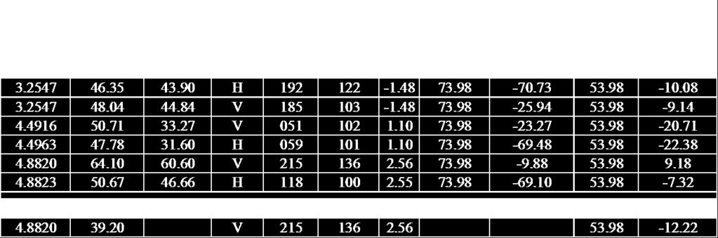
64 8PSK CHANNEL 79: 2480 MHZ BAND EDGE MEASUREMENT Marker 2 [T1] RBW 100 khz RF Att 50 db Ref Lvl dbm VBW 300 khz 10 dbm GHz SWT 200 ms Unit dbm D1 1.5 dbm 2 [T1] dbm GHz 1 [T1] 1.48 dbm A GHz VIEW D dbm IN1 1MA P TDF F1-90 Center GHz 1 MHz/ Span 10 MHz Date: 1.NOV :12:55 Test Results: The Band Edge measurements for Bluetooth Frequencies of the ARRIS Model VMS4100 Set Top Box are compliant with the limits specified in FCC Section (d). Page 64 of 69

65 4.13 Antenna Port, Power Spectral Density (47 CFR (f)) (03/21/2017) The VMS4100 employs a combination of both frequency hopping and digital modulation techniques. Therefore, the power spectral density, conducted from the transmitter to the antenna due to the digital modulation operation of the hybrid system, with the frequency hopping operation turned off shall not be greater than 8 dbm in any 3 khz band during continuous transmission. GFSK GHz Marker 1 [T1] RBW 3 khz RF Att 50 db Ref Lvl dbm VBW 10 khz 10 dbm GHz SWT 10 s Unit dbm [T1] dbm GHz A IN1 1MAX 1MA P20 TDF Center 2.48 GHz 150 khz/ Span 1.5 MHz Date: 21.MAR :11:01 Test Results: Power Spectral Density of the VMS4100 complied with the requirements of CFR Part (f) with a margin of db. Page 65 of 69


66 5.0 Test Setup Pictures 5.1 Conducted Emissions Power Line Test Setup Picture 5.2 Conducted Emissions Antenna Test Setup Picture Page 66 of 69


67 5.3 Radiated Emissions MHz Test Setup Picture 5.4 Radiated Emissions 1 25 GHz Test Setup Picture Page 67 of 69
68 Appendix A Test Equipment Equipment Manufacturer Model # Serial # BEC # Calibration Date Calibration Cycle Calibration Due Date EMI Receiver (20 Hz 26.5 GHz) Antenna (30 MHz - 6 GHz) Rohde & Schwarz Sunol Sciences ESIB / /01/16 2 Years 07/01/18 JB6 A /01/16 2 Years 04/01/18 9kHz-3GHz EMC Analyzer Agilent E7402A US /16/16 2 Years 02/16/18 Amplifier ( MHz) Hewlett Packard 8447F 2805A No Cal. Required No Cal. Required No Cal. Required EMC Analyzer (9 khz GHz) GTEM (30 MHz 1 GHz) Spectrum Analyzer (9 khz - 40 GHz) EMC Analyzer (9 khz GHz) Hewlett Packard ETS Lindgren Hewlett Packard Hewlett Packard 8591EM 3536A /14/14 3 Years 10/14/ No Cal. Required No Cal. Required No Cal. Required 8564E 3410A /29/15 3 Years 12/29/ EM 3710A /02/17 2 Years 03/02/19 Amplifier System ( GHz) Hewlett Packard 83015A 83017A 3123A00360 & 3332A /03/16 2 Year 10/03/18 Double Ridged Horn Antenna (1-18 GHz) EMCO /19/16 2 Years 10/19/18 Page 68 of 69
69 Antenna ( GHz) Hewlett Packard N/A /19/16 2 Years 10/19/18 EMI Receiver (9 khz GHz) Hewlett Packard 8546A 3325A /13/16 3 Years 12/13/19 LISN (9 khz 30 MHz) EMCO 4825/ /21/15 2 Years 04/21/17 Shielded Room #1 ETS Lindgren 12-2/ /16/15 2 Years 12/16/17 Intentional Radiator Testing High Frequency RF Test Cable Workhorse WHU N/A /04/16 2 Years 12/04/18 OATS Site (30 MHz 1 GHz) BEC N/A N/A /09/16 1 Year 05/09/17 Temp/Humidity Meter Control Company /19/15 2 Years 11/19/17 Software (Tile Instrument Control System) Quantum Change/EMC Systems Version 3 N/A N/A No Cal. Required No Cal. Required No Cal. Required Radiated Emissions Test Software BEC RADE 2.2 N/A No Cal. Required No Cal. Required No Cal. Required Page 69 of 69
CERTIFICATION APPLICATION TEST REPORT
 BEC INCORPORATED CERTIFICATION APPLICATION TEST REPORT TEST STANDARDS: FCC Part 15 Subpart C, Section 15.247 Intentional Radiator ARRIS Model VMS4100 Set Top Box FCC ID: ACQ-VMS4100 REPORT BEC-1792-03
CONTENTS 1. GENERAL INFORMATION INTRODUCTION PRODUCT INFORMATION DESCRIPTION OF TESTS CHANNEL BANDWIDTH...
 Test Report Number : GETEC-E3-09-083 Page 2 / 33 CONTENTS. GENERAL INFORMATION...4 2. INTRODUCTION...5 3. PRODUCT INFORMATION...6 3. DESCRIPTION OF EUT...6 3.2 SUPPORT EQUIPMENT / CABLES USED...7 3.3 MODIFICATION
TEST REPORT FROM RFI GLOBAL SERVICES LTD
 TEST REPORT FROM RFI GLOBAL SERVICES LTD Test of: D-MINI-2108-2019 FCC ID: NEO-DMINI21082019 To: FCC Parts 2.1046; 2.1049; 22.913(a); 22.917; 24.232; 24.238 & 15.107 3GPP TS 36.143 V10.3.0 This Test Report
FCC PART TEST REPORT. HHC Changzhou Corp.
 FCC PART 15.249 TEST REPORT For HHC Changzhou Corp. No 61, Xinggang Road, Zhonglou District, Changzhou, Jiangsu, China, 213023 FCC ID: 2AEQWCB20HHC011 Report Type: Original Report Product Type: Control
FCC PART TEST REPORT SHANGHAI MERIT TECHNOLOGY CORP.
 FCC PART 15.247 TEST REPORT For SHANGHAI MERIT TECHNOLOGY CORP. 1058 TAOGAN RD., SHESHAN TOWN, SONGJIANG DISTRICT, SHANGHAI, China FCC ID: XJ6MT-180H Report Type: Original Report Product Type: 4CH 2.4GHZ
FCC ID: IMK-ILCISA EMI TEST REPORT
 15.247 Certification FCC ID: IMK-ILCISA EMI TEST REPORT On SYMPHONY ISA Card Prepared for Proxim 295 N. Bernardo Ave Mountain View, CA 94043 Tel: (650)960-1630 Fax: (650)960-0332 Prepared by Electronic
FCC Part 15 Subpart B Test Report. FCC PART 15 Subpart B Class B: 2014
 Shenzhen CTL Electromagnetic Technology Co., Ltd. Tel: +86-755-89486194 Fax: +86-755-26636041 FCC Part 15 Subpart B Test Report FCC PART 15 Subpart B Class B: 2014 Report Reference No...: CTL1408272147-F
TEST REPORT. Test Report No. : UL-RPT-RP JD18L V2.0. Manufacturer : Neeo AG. Model No. : 6336-BRAIN FCC ID : 2AKK7-BR633601
 TEST REPORT Test Report No. : UL-RPT-RP11456397JD18L V2.0 Manufacturer : Neeo AG Model No. : 6336-BRAIN FCC ID : 2AKK7-BR633601 Test Standard(s) : FCC Part 15.207 1. This test report shall not be reproduced
TEST REPORT FROM RFI GLOBAL SERVICES LTD
 FROM RFI GLOBAL SERVICES LTD Test of: Blighter B422-HPNB Aux Unit FCC ID: UFQB400HPNBAUX To: FCC Part 90: 2010 Subpart F in accordance with RFI Test Plan RFI/REGE1/TP75565JD03 Test Report Serial No: RFI-RPT-RP76945JD15B
FCC PART 15C TEST REPORT FOR CERTIFICATION On Behalf of NYNE MULTIMEDIA INC. Bluetooth Speaker. Model Number: NYNE VIBE FCC ID: AWA-NYNEVIBE
 FCC PART 15C TEST REPORT FOR CERTIFICATION On Behalf of NYNE MULTIMEDIA INC. Bluetooth Speaker Model Number: NYNE VIBE FCC ID: AWA-NYNEVIBE Prepared for: NYNE MULTIMEDIA INC. 3451 LUNAR COURT, OXNARD,
TEST REPORT. Test Report No. : UL-RPT-RP C V2.0. Date of Issue: 06 March 2018
 Test Report No. : UL-RPT-RP11913492-2216C V2.0 Manufacturer : Raspberry Pi (Trading) Ltd Model No. : Raspberry Pi 3 Model B+ FCC ID : 2ABCB-RPI3BP Technology : Bluetooth Low Energy Test Standard(s) : FCC
FCC PART 15 CLASS B MEASUREMENT AND TEST REPORT. Tritech Technology Ltd.
 FCC PART 15 CLASS B MEASUREMENT AND TEST REPORT For Tritech Technology Ltd. Unit 8B,Chung pont Commercial Building No.300 Hennessy Road, Wanchai, HongKong Model: 0-545-24967-8, 0-545-24986-4 Report Type:
CENTRE OF TESTING SERVICE INTERNATIONAL
 CENTRE OF TESTING SERVICE INTERNATIONAL OPERATE ACCORDING TO ISO/IEC 17025 IC TEST REPORT TEST REPORT NUMBER : CGZ3150202-00095-E A101,No.65,Zhuji Highway,Tianhe District,Guangzhou, Guangdong, China TEST
FCC REPORT Q6WBT * In the configuration tested, the EUT complied with the standards specified above.
 1 Cover Page Report No: CCIS12110026101 FCC REPORT Applicant: Address of Applicant: Equipment Under Test (EUT) GUANGDONG STEELMATE SECURITY CO., LTD Renan Street, Dong fu Road, Dongfeng Town,Zhongshan,
Testing. Maker Works. Applicant: Model No.: FCC ID: Jun., May to 16. Date of Test: PASS* Test Result: Signature: Authorized. this report.
 1 Cover Page Shenzhen Zhongjian Nanfang Testing Co., Ltd. FCC REPORT Applicant: Address of Applicant: Maker Works Technology INC Building C3, Floor 4th, Zhiyuan, Xili, Nanshan District, ShenZhen 518057
T E S T - R E P O R T. No for. SLG 42 MOBY Component
 Straubing, August 04, 1998 T E S T - R E P O R T No. 51905-80643-0 for SLG 42 MOBY Component Applicant: Purpose of Testing: Siemens AG To show compliance with FCC Rules Part 15, Subpart C section 15.209
FCC TEST REPORT for Aeon Labs LLC. Aeon Minimote Model No.: DS03202B-ZWUS, DS03202W-ZWUS
 Page 1 of 22 FCC TEST REPORT for Aeon Labs LLC. Aeon Minimote Model No.: DS03202B-ZWUS, DS03202W-ZWUS Prepared for Address Prepared By Address : Aeon Labs LLC. : 121 Buckingham drive, unit36 santa claras
Report On. FCC Testing of the Pace Plc 16x4 Hybrid Gateway Cable Set Top Box COMMERCIAL-IN-CONFIDENCE
 Report On FCC Testing of the Pace Plc 16x4 Hybrid Gateway Cable Set Top Box Document 75926325 Report 01 Issue 1 April 2014 TÜV SÜD Product Service, Octagon House, Concorde Way, Segensworth North, Fareham,
Sunlight Supply, Inc.
 FCC Part 18 Subpart C Consumer For RF Lighting Equipment Electromagnetic Compatibility Test Report Sunlight Supply, Inc. Etelligent Compatible Ballast - olt July 19, 2017 Tests Conducted by:, LLC 20811
EMC Test Report. 850 Kacena Road Hiawatha, IA 52233
 EMC Client: EUT: Crystal Group 850 Kacena Road Hiawatha, IA 52233 Model RS112 No.: R20140819-21 Approved By: Nic S. Johnson, NCE EMC Test Engineering Manager/Technical Manager inarte Certified EMC Engineer
CONTENTS 6.2 TEST SET-UP...16
 CONTENTS 1. GENERAL INFORMATION...3 2. INTRODUCTION...4 3. PRODUCT INFORMATION...5 3.1 DESCRIPTION OF EUT...5 3.2 SUPPORT EQUIPMENT / CABLES USED...6 3.3 MODIFICATION ITEM(S)...6 4. DESCRIPTION OF TESTS...7
EUROFINS PRODUCT SERVICE GMBH. Testing Cert # Compliance Test Report FCC PART 15 SUBPART C IC RSS 210 ISSUE 7
 EUROFINS PRODUCT SERVICE GMBH Testing Cert #1983.01 TEST- REPORT Compliance Test Report FCC PART 15 SUBPART C IC RSS 210 ISSUE 7 FCC ID: T7V1315 IC ID: 216Q-1315 Bluetooth module ENW89818C2JF PAN1315 TEST
Test Report. Product Name: Access Point Model No.: MS-6809 FCC ID: DoC
 Test Report Product Name: Access Point Model No.: MS-6809 FCC ID: DoC Applicant : MICRO-STAR INT L Co., LTD Address : No 69, Li-De st., Jung-He City, Taipei Hsien, Taiwan, R.O.C Date of Receipt : June
FCC PART MEASUREMENT AND TEST REPORT FOR. DongGuan City FLYSKY Remote Model Co., Ltd.
 FCC PART 15.249 MEASUREMENT AND TEST REPORT FOR DongGuan City FLYSKY Remote Model Co., Ltd. No.41 Road West, BanHu Village, HuangJiang Town, DongGuan City, GuangDong Porvince, China FCC ID: VPOFLYSKY002
FCC PART 15B, CLASS B TEST REPORT. Autel Intelligent Tech. Corp., Ltd.
 FCC PART 15B, CLASS B TEST REPORT For Autel Intelligent Tech. Corp., Ltd. 6th - 10th Floor, Bldg. B1, Zhiyuan, Xueyuan Rd., Xili, Nanshan Shenzhen China FCC ID: WQ8MAXISYSMY906 Report Type: Original Report
T E S T - R E P O R T. No for PC24E-11-FC/R. RF-modem for wireless LAN. Agere Systems Nederland B.V.
 EMV-Prüfzentrum EMI/EMC-Testcenter Straubing, September 5, 2001 T E S T - R E P O R T No. 56305-10552-1 for RF-modem for wireless LAN Purpose of testing: To show compliance with FCC Code of Federal Regulations,
FCC PART 15C TEST REPORT FOR CERTIFICATION On Behalf of. Guangzhou Panyu Juda Car Audio Equipment Co.,Ltd. CD/USB RADIO. Model Number: TY-CWU700
 FCC PART 15C TEST REPORT FOR CERTIFICATION On Behalf of Guangzhou Panyu Juda Car Audio Equipment Co.,Ltd. CD/USB RADIO Model Number: TY-CWU700 FCC ID: ESX-CWU700 Prepared for : Guangzhou Panyu Juda Car
FCC Report. Beijing Visual World Technology Co.,Ltd.
 FCC Report Report No.: GTS201703000097F01 Applicant: Beijing Visual World Technology Co.,Ltd. Address of Applicant: 15th Floor and 17th Floor 1701-10A, Building 3, No. 10, Jiuxianqiao Road Jia, Chaoyang
Test Report. Model No.: NF592XX-YYYY-ZZ(X,Y & Z: Stands for A-Z & 0-9 ) HBJC1XXF592-YYYY-ZZ (X,Y & Z: Stands for A-Z & 0-9 )
 HBJC1XXF592-YYYY-ZZ (X,Y & Z: Stands for A-Z & 0-9 )") Test Report Applicant: Product Name: Brand Name: Jetway Information Co.,Ltd Motherboard/Barebone N/A Model No.: NF592XX-YYYY-ZZ(X,Y & Z: Stands for A-Z & 0-9 ) HBJC1XXF592-YYYY-ZZ (X,Y & Z: Stands for
Test Report Applicant: Product Name: Brand Name: Jetway Information Co.,Ltd Motherboard/Barebone N/A Model No.: NF592XX-YYYY-ZZ(X,Y & Z: Stands for A-Z & 0-9 ) HBJC1XXF592-YYYY-ZZ (X,Y & Z: Stands for
FCC PART 22H, PART 24E MEASUREMENT AND TEST REPORT. Shanghai AirM2M Communication Technology Co., Ltd
 FCC PART 22H, PART 24E MEASUREMENT AND TEST REPORT For Shanghai AirM2M Communication Technology Co., Ltd No. 666.East beijing road, Shanghai, China FCC ID: 2AEGG-AIR208 Report Type: Original Report Product
TABLE OF CONTENTS 1. GENERAL INFORMATION PRODUCT DESCRIPTION FOR EQUIPMENT UNDER TEST (EUT) TEST STANDARDS TEST METHODOLOGY
 TEST STANDARDS TEST METHODOLOGY") FCC Rule(s): FCC Part 15B Measurement and Test Report Product Description: Tested Model: Report No.: For GlobTek, Inc. 186 Veterans Dr. Northvale, NJ 07647 USA FCC Part 15 Subpart B X-PLORE 8000 STANDARD
FCC Rule(s): FCC Part 15B Measurement and Test Report Product Description: Tested Model: Report No.: For GlobTek, Inc. 186 Veterans Dr. Northvale, NJ 07647 USA FCC Part 15 Subpart B X-PLORE 8000 STANDARD
Shenzhen Zhongjian Nanfang Testing Co., Ltd.
 Report No: CCIS15010007003 1 Cover Page FCC REPORT Applicant: Address of Applicant: Interglobe Connection Corp 7500 NW 25 th Street 112 Miami, Florida 33122 USA Equipment Under Test (EUT) Product Name:
FCC Part 15B Test Report
 Shenzhen Toby Technology Co., Ltd. Report No.: TB-FCC111757 Page: 1 of 18 FCC Part 15B Test Report Application No. : TB11081419 Applicant : Ingtron Enterprise Co., Ltd. Equipment Under Test (EUT) EUT Name
Test Report #: Date: January 24, 2006
 Test Report #: 2415-1 Date: January 24, 2006 CERTIFICATE #2316.01 Issued To: Jeffrey Samstad American Power Conversion 85 Rangeway Road North Billerica, MA 01862 USA 978-670-2440 Product Name/Description
FCC test report. Via Pezza Alta, 13 I Rustignè di Oderzo (TV)
") Test report nr. 20811FCC11 Measurements performed in accordance with: FCC Rules: code of Federal Regulations (CFR) no. 47 PART 15 RADIO FREQUENCY DEVICES Product: Tested model: FCC ID Applicant: Manufacturer:
Test report nr. 20811FCC11 Measurements performed in accordance with: FCC Rules: code of Federal Regulations (CFR) no. 47 PART 15 RADIO FREQUENCY DEVICES Product: Tested model: FCC ID Applicant: Manufacturer:
FCC Report (WIFI) Shenzhen Reo-link Digital Technology Co., Ltd B509, University Town Business Park LiShan Road, NanShan, Shenzhen, Guangdong, China
 Shenzhen Reo-link Digital Technology Co., Ltd B509, University Town Business Park LiShan Road, NanShan, Shenzhen, Guangdong, China") FCC Report (WIFI) Applicant: Address of Applicant: Manufacturer/y: Address of Manufacturer/y: Equipment Under Test (EUT) Product Name: Shenzhen Reo-link Digital Technology Co., Ltd B509, University Town
FCC Report (WIFI) Applicant: Address of Applicant: Manufacturer/y: Address of Manufacturer/y: Equipment Under Test (EUT) Product Name: Shenzhen Reo-link Digital Technology Co., Ltd B509, University Town
FCC TEST REPORT For. ETI Solid State Lighting (Zhuhai) Ltd. LED downlight Model No.: XX
 Ltd. LED downlight Model No.: XX") Page 1 of 24 FCC TEST REPORT For ETI Solid State Lighting (Zhuhai) Ltd LED downlight Model No.: 531931XX Prepared for Address Prepared by Address : ETI Solid State Lighting (Zhuhai) Ltd : No.1, Zhongzhu
Page 1 of 24 FCC TEST REPORT For ETI Solid State Lighting (Zhuhai) Ltd LED downlight Model No.: 531931XX Prepared for Address Prepared by Address : ETI Solid State Lighting (Zhuhai) Ltd : No.1, Zhongzhu
Guangzhou Panyu Juda Car Audio Equipment Co.,Ltd. Bluetooth Speaker. Model Number: UB-SPB4M-101 FCC ID: ESXSPB4M
 FCC ID: ESXSPB4M FCC PART 15C TEST REPORT FOR CERTIFICATION On Behalf of Guangzhou Panyu Juda Car Audio Equipment Co.,Ltd. Bluetooth Speaker Model Number: UB-SPB4M-101 FCC ID: ESXSPB4M Prepared for : Guangzhou
CENTRE OF TESTING SERVICE INTERNATIONAL OPERATE ACCORDING TO ISO/IEC FCC ID TEST REPORT
 CENTRE OF TESTING SERVICE INTERNATIONAL OPERATE ACCORDING TO ISO/IEC 17025 FCC ID TEST REPORT TEST REPORT NUMBER : CGZ3150520-00565-EF TEST REPORT For FCC ID 47 CFR PART 15 OCT, 2014 Report Reference No....
BT SOUND BAR. Model Number: AR2010 SBT2014, SBT2014XX, SBT2015,SBT2015XX, ER822FL FCC ID: RI5AR2010
 FCC ID: RI5AR2010 FCC PART 15C TEST REPORT FOR CERTIFICATION On Behalf of Dongguan Earson Audio Technology Co., Ltd BT SOUND BAR Model Number: AR2010 Additional Model:AR2010XX, AR3002, AR3002XX, SBT2014,
FCC Report (WIFI) Red Bear Company Limited. RedBear IoT phat 2ABXJ-PHAT-IOT
 Red Bear Company Limited. RedBear IoT phat 2ABXJ-PHAT-IOT") Report No.: GTS201607000065E01 FCC Report (WIFI) Applicant: Red Bear Company ed Address of Applicant: 1711 Block B, Wah Luen Industrial Centre, 15-21 Wong Chuk Yeung Street, Fo Tan, Hong Kong Equipment
Report No.: GTS201607000065E01 FCC Report (WIFI) Applicant: Red Bear Company ed Address of Applicant: 1711 Block B, Wah Luen Industrial Centre, 15-21 Wong Chuk Yeung Street, Fo Tan, Hong Kong Equipment
Order Number : GETEC-C FCC Part 15 subpart B Test Report Number : GETEC-E Page 2 / 32 CONTENTS
 Test Report Number : GETEC-E3-12-032 Page 2 / 32 CONTENTS 1. GENERAL INFORMATION... 3 2. INTRODUCTION... 4 3. PRODUCT INFORMATION... 5 3.1 DESCRIPTION OF EUT... 5 3.2 SUPPORT EQUIPMENT / CABLES USED...
FCC Test Report (Class II Permissive Change)
") FCC Test Report (Class II Permissive Change) Product Name Intel Wireless-AC 9560 Model No. 9560NGW FCC ID. 2AKHF9560NG Applicant TONGFANG HONGKONG (SUZHOU) LIMITED Address NO. 83 Wu Lane, Suzhou Industrial
FCC Test Report (Class II Permissive Change) Product Name Intel Wireless-AC 9560 Model No. 9560NGW FCC ID. 2AKHF9560NG Applicant TONGFANG HONGKONG (SUZHOU) LIMITED Address NO. 83 Wu Lane, Suzhou Industrial
FCC Report (WIFI) Shenzhen SDMC Technology Co., Ltd 2AFC2-STB-1HD. * In the configuration tested, the EUT complied with the standards specified above.
 Shenzhen SDMC Technology Co., Ltd 2AFC2-STB-1HD. * In the configuration tested, the EUT complied with the standards specified above.") Report No.: GTSE15080158301 FCC Report (WIFI) Applicant: Shenzhen SDMC Technology Co., Ltd Address of Applicant: 7/F, W2-A Bld, Gaoxin S. Av. 4, Hi-tech Park, Nanshan, Shenzhen, China Equipment Under Test
Report No.: GTSE15080158301 FCC Report (WIFI) Applicant: Shenzhen SDMC Technology Co., Ltd Address of Applicant: 7/F, W2-A Bld, Gaoxin S. Av. 4, Hi-tech Park, Nanshan, Shenzhen, China Equipment Under Test
Shenzhen Zhongjian Nanfang Testing Co., Ltd.
 Report No: CCIS3667. Cover page FCC REPORT (Mobile Phone) Applicant: Address of Applicant: Equipment Under Test (EUT) NETLET ELECTRONICS (HONG KONG) LIMITED 2/F., San Toi Building,37-39 Connaught Road
FCC Part 15 Certification Test Report. 433 MHz Alarm System
 FCC Part 15 Certification Test Report 433 MHz Alarm System FCC ID: Q6K 1000-7253 FCC Rule Part: 15.231 ACS Report Number: 03-0111-15B Manufacturer: 3SI Security Systems Model: 1000-7253 with variants Test
RF Test Report: Airspan ib440 to 47CFR SC_TR_150_B
 RF Test Report: irspan ib44 to 47CFR5.247 FCC ID: O2J-iB44 SC_TR_5_B Prepared for: irspan Communications Ltd Capital Point, 33 Bath Road Slough, Berkshire SL 3UF Sulis Consultants Limited Mead House, Longwater
EMC Test Report. Client: Continental Automotive Systems, Inc. Tested by: Fendy Liauw, Engineering Technician
 Test Report Number: 3953917EMC7 Rev: Page: 1 of 35 EMC Test Report Project Number: 3953917 Report Number: 3953917EMC7 Revision Level: Client: Continental Automotive Systems, Inc. Equipment Under Test:
ELECTRICAL TESTING FOR:
 ELECTRICAL TESTING 0839.01 Hermon Laboratories Ltd. Harakevet Industrial Zone, Binyamina 30500, Israel Tel. +972-4-6288001 Fax. +972-4-6288277 E-mail: mail@hermonlabs.com TEST REPORT ACCORDING TO: FCC
Improving the accuracy of EMI emissions testing. James Young Rohde & Schwarz
 Improving the accuracy of EMI emissions testing James Young Rohde & Schwarz Q&A Who uses what for EMI? Spectrum Analyzers (SA) Test Receivers (TR) CISPR, MIL-STD or Automotive? Software or front panel?
REPORT Datum/Date Beteckning/Reference Sida/Page
 2002-10-25 F219009-F24 1 (1) FCC ID: B5KPROJ1192211-1 Rev. 2003-01-16 Encl. 1 Description - Equipment Under Test (EUT) Equipment: Tx Frequency range: Tested Channel: WCDMA Base station transceiver 1900
FCC PART 15 CLASS B EMI MEASUREMENT AND TEST REPORT
 FCC PART 15 CLASS B EMI MEASUREMENT AND TEST REPORT For XIAMEN YEALINK NETWORK TECHNOLOGY CO., LTD. 7/F HuaLian Electronic BLDG., No.580 JiaHe Road, XiaMen, China September 26, 2005 This Report Concerns:
FCC Test Report (Part 15C) WPT
 WPT") FCC Test Report (Part 15C) WPT Test Report no.: EMC_BO_002127 (v3.0) Date of Report: 14-Dec-2017 Number of pages: 15 Project support engineer: Frank Wittmann Test period: 02.10.-26.10.2017 Applicant: Manufacturer:
FCC Test Report (Part 15C) WPT Test Report no.: EMC_BO_002127 (v3.0) Date of Report: 14-Dec-2017 Number of pages: 15 Project support engineer: Frank Wittmann Test period: 02.10.-26.10.2017 Applicant: Manufacturer:
APPLICATION OF CERTIFICATION For. TTE Technology Inc. LCD TV FCC ID: W8ULE32HDE3000
 FCC ID:W8ULE32HDE3000 APPLICATION OF CERTIFICATION For TTE Technology Inc. LCD TV Brand Name TCL Model Number LE32HDE3000; LE32HDE3011 LE32HDE5311; LE32HDF3310TA LE32HDF3311; LE32HDF3312 FCC ID: W8ULE32HDE3000
TEST REPORT. Power Spout PLT V. tested to. 47 Code of Federal Regulations. Part 15 - Radio Frequency Devices
 EMC Technologies (NZ) Ltd PO Box 68-307,Newton Auckland 1145 New Zealand Phone 09 360 0862 Fax 09 360 0861 E-Mail Address: aucklab@ihug.co.nz Web Site: www.emctech.com.au TEST REPORT Power Spout PLT 100
TEST REPORT. Report Number: MPK-003B Project Number: G October 20, 2017
 TEST REPORT Report Number: 13224477MPK-3B Project Number: G13224477 October 2, 217 Testing performed on the FIBERGATEWAY Model Number: GR24BG FCC ID: 2ACJF-FGW-GR24BG to FCC Part 15, Subpart E For Altice
Page: 1 of 15 FCC TEST REPORT. : MEGAVIEW DIGITECH LIMITED : C Fu Gui Yuan, Block 80, Bao an District, Shenzhen, China
 Page: 1 of 15 FCC TEST REPORT Reference No. Applicant Address : WT10125265-S-E-F : MEGAVIEW DIGITECH LIMITED : C1-1001 Fu Gui Yuan, Block 80, Bao an District, Shenzhen, China Equipment Under Test (EUT)
Sensoray. Model 819. Tests Conducted by: ElectroMagnetic Investigations, LLC. May 10, 2013
 European Union (EU) Council Directive 2004/108/EC Electromagnetic Compatibility (EMC) and FCC Part 15 Subpart B Class B Test Report for Information Technology Equipment Sensoray Model 819 May 10, 2013
CHAO WEI ELECTRONICS CO., LTD. FCC REPORT CHAO WEI ELECTRONICS CO., LTD.
 CHAO WEI ELECTRONICS CO., LTD. FCC REPORT Prepared For : CHAO WEI ELECTRONICS CO., LTD. No.8, Xianglong Road, Xiagang, Changantown, Dongguan City, China Product Name: Model : DVB-T ANTENNA CW-DVB66, CW-DVB83,
FCC PART 15 TEST REPORT
 FCC PART 15 TEST REPORT No. I17Z60314SRD06 for HMD Global Oy Smart Phone TA-1033 with FCC ID: 2AJOTTA-1033 Hardware Version: 3 Software Version: 000C_3_050 Issued Date: 2017-04-17 Note:The test results
FCC Test Report (Class II Permissive Change)
") FCC Test Report (Class II Permissive Change) Product Name 802.11abgn/11ac WLAN + Bluetooth PCI-E Mini Card Model No BCM94360HMB FCC ID QDS-BRCM1082 Applicant Broadcom Corporation Address 190 Mathilda Place
FCC Test Report (Class II Permissive Change) Product Name 802.11abgn/11ac WLAN + Bluetooth PCI-E Mini Card Model No BCM94360HMB FCC ID QDS-BRCM1082 Applicant Broadcom Corporation Address 190 Mathilda Place
FCC Radio Test Report
 Shenzhen Toby Technology Co., Ltd. Report No.: TB-FCC163268 Page: 1 of 153 FCC Radio Test Report FCC ID: 2AL8K-H5 Report No. : TB-FCC163268 Original Grant Applicant : NZS Inc. DBA Clary Icon Equipment
EMC Test Report. Client: Crestron Electronics, Inc. Tested by: Jeremy O. Pickens, Senior EMC Engineer
 Test Report Number: 3919823EMC1 Rev. Page: 1 of 26 EMC Test Report Project Number: 3919823 Report Number: 3919823EMC1 Revision Level: Client: Crestron Electronics, Inc. Equipment Under Test: infinet EXTM
FCC TEST REPORT D-LINK CORPORATION
 FCC TEST REPORT REPORT NO.: RF921014R02 MODEL NO.: DWL-120(refer to page 6 for other models) RECEIVED: October 14, 2003 TESTED: October 16 ~ October 17, 2003 APPLICANT: ADDRESS: D-LINK CORPORATION NO.8,
A Test Lab Techno Corp. FCC. RF Test Report. Product Type. : Mobile Hotspot. Applicant. : Netgear Inc.
 FCC RF Test Report Product Type Applicant : Mobile Hotspot : Netgear Inc. Address : 350 East Plumeria Drive, San Jose, CA 95134 Trade Name Model Number Test Specification : NETGEAR : AC810S-300 : FCC 47
FCC PART RSS-GEN, ISSUE 5, APRIL 2018 RSS-247, ISSUE 2, FEBRUARY 2017 TEST REPORT SZ DJI TECHNOLOGY CO., LTD
 FCC PART 5.247 RSS-GEN, ISSUE 5, APRIL 208 RSS-247, ISSUE 2, FEBRUARY 207 TEST REPORT For SZ DJI TECHNOLOGY CO., LTD 4th floor, West Wing, Skyworth Semiconductor Design Building NO.8 Gaoxin South 4th Ave,
R&TTE EMC TEST REPORT
 No. 1 Workshop, M-10, Middle section, Science & Technology Park, Shenzhen, Guangdong, China 518057 Telephone: +86 (0) 755 2601 2053 Fax: +86 (0) 755 2671 0594 Email: sgs_internet_operations@sgs.com Application
ONETECH Testing & Eval. Lab. VERIFICATION FCC RULES PARTS 2 & 15 CLASS A DIGITAL DEVICE. for AUTHORIZED. Win4NET Co., Ltd.
 ONETECH Testing & Eval. Lab. VERIFICATION FCC RULES PARTS 2 & 15 CLASS A DIGITAL DEVICE for PRODUCT: VIDEO CODEC MODEL NAME: NetSafe-VC3001 AUTHORIZED Win4NET Co., Ltd. KOLON Digital Tower 1301, 222-7,
FCC PART 15 TEST REPORT
 FCC PART 15 TEST REPORT for Huawei Technologies Co.,Ltd tablet Model Name: T1-A1w FCC ID: QIST1-A1W with Hardware Version: SH1T1A1LM Software Version: T1-A1wV1R1C1 Issued Date: 15--15 TESTING CNAS L57
Test result 1. Conducted emission EN 55022: A1:2007 EA 3 passed 2. Radiated emission <1GHz (others)
") SHARP EMC Testing Laboratory Test Report No.: 11/250-02 page TR-2 of TR-13 5 SUMMARY OF TEST RESULTS Emission testing No. Item Test procedure Page code Number of pages Test result 1. Conducted emission
SHARP EMC Testing Laboratory Test Report No.: 11/250-02 page TR-2 of TR-13 5 SUMMARY OF TEST RESULTS Emission testing No. Item Test procedure Page code Number of pages Test result 1. Conducted emission
Date: ESPOO Page: 1 (10) Appendices. Tyre Pressure Monitoring Device. Flextronics International Finland.
 Appendices. Tyre Pressure Monitoring Device. Flextronics International Finland.") TEST REPORT Date: ESPOO 25.04.2003 Page: 1 (10) Appendices Number: 1031681 No.1/1 Date of handing in: 07.04.2003 Testedby: Timo Leismala, Product Manager Reviewed by: Janne Nyman, Product Manager, EMC
TEST REPORT Date: ESPOO 25.04.2003 Page: 1 (10) Appendices Number: 1031681 No.1/1 Date of handing in: 07.04.2003 Testedby: Timo Leismala, Product Manager Reviewed by: Janne Nyman, Product Manager, EMC
Test Report. Applicant Address. : WALTOP International Corp. : 6F,No.19-1 Industry E.Rd.IV,Hsinchu Science Park,Hsin-Chu 30077,Taiwan,R.O.C.
 Test Report Product Name : Tablet: Wireless Tablet X86/X86; Dongle: Wireless Tablet Receiver X86/X86 Model No. : Tablet: RCK-T7, RCK-T7S; Dongle: RCK-T7R, RCK-T7RS FCC ID. : Tablet: UBBRCKT7, Dongle: UBBRCKT7R
Spectrum Analyzer 1.6 GHz 3 GHz R&S HMS-X
 HMS-X_bro_de-en_3607-0181-3X_v0200.indd 1 Product Brochure 02.00 Test & Measurement Spectrum Analyzer 1.6 GHz 3 GHz R&S HMS-X 15.03.2016 15:24:06 1 Basic Unit + 3 Options Key facts Frequency range: 100
FCC TEST REPORT North Mathilda Avenue, Sunnyvale, California Advance Data Technology Corporation
 FCC TEST REPORT REPORT NO.: RF931119H01 NO.: RECEIVED: Nov. 19, 2004 TESTED: Dec. 22, 2004 to Jan. 05, 2005 ISSUED: Jan. 17, 2005 APPLICANT: ADDRESS: Juniper Networks 1194 North Mathilda Avenue, Sunnyvale,
FCC PART TEST REPORT. Hantat Technology Ltd.
 FCC PRT 5.247 TEST REPORT For Hantat Technology Ltd. 3/F., C Building, Fuxinlin Industrial Park, Hangch,Xixiang Town, Banan District,Shenzhen,China,5826 FCC ID: V3NHB67 Report Type: Original Report Product
Open Rack Specification 2.1 Update
 Rack and Power Open Rack Specification 2.1 Update Steve Mills Technical Lead Facebook Busbar Thickness Tolerance Reduction Reduce Rack Frame Tolerance Agenda Add Appendix D: Optional Rack-level EMI test
FCC Test Report. Color LCD Monitor
 Underwriters Laboratories Inc. www.ul.com/emc www.ulk.co.kr Project: 10CA46552 File: TC8352 Report: 10CA46552-FCC Date: October 13, 2010 Model: EX190W (Basic), RadiForce EX190W FCC Test Report For Color
Out of Band Spurious Measurement for Bluetooth Modules
 Products: Signal Analyser FSIQ26/FSP13/FSU8/FSQ26 Out of Band Spurious Measurement for Bluetooth Modules This application notes describes the out of band Spurious emission measurement for Bluetooth modules
ANSI C63.4 and CISPR 22-Harmony
 ANSI C63.4 and CISPR 22-Harmony at Last? Donald N. Heirman Lucent Technologies, Bell Laboratories Innovations Holmdel, New Jersey 07738 USA Abstract: This paper compares the most prevalent emission measurement
FCC Test Report (Bluetooth)
") Report No.: T479F Page: of 52 FCC Test Report (Bluetooth) FCC ID : 8IVOOMBOX-ONGO pplicant : Shenzhen DIVOOM Technology Co., Ltd. 3, 2nd Floor, Block, Zhengxing Building, No. 33 Taizi Road, Shekou, Nanshan
Report No.: T479F Page: of 52 FCC Test Report (Bluetooth) FCC ID : 8IVOOMBOX-ONGO pplicant : Shenzhen DIVOOM Technology Co., Ltd. 3, 2nd Floor, Block, Zhengxing Building, No. 33 Taizi Road, Shekou, Nanshan
SIGFOX END- PRODUCT RADIATED TEST PLAN FOR SIGFOX READY TM CERTIFICATION
 May 23 th 2018 SIGFOX END- PRODUCT RADIATED TEST PLAN FOR SIGFOX READY TM CERTIFICATION Public use Revision History Revision Number Date Author Change description 0.1 August 15 th, 2017 B.Ray Initial spec
Page: 1 of 19 EMC TEST REPORT EN55024:1998+A2:2003
 Page: 1 of 19 EMC TEST REPORT Reference No. Applicant : WT05110894 : Gembird Electronics Ltd. Equipment Under Test (EUT) : Product Name : Card reader Model No : USB2.0A LL-in-1 Standards : EN55022:1998+A2:2003
BlueRadios BR-LE4.0-D2A N/A. BlueRadios, Inc.
 TEST REPORT of R&TTE (1999/5/EC ) Directive ETSI EN 300 328 V1.7.1: 2006 Product : Brand: Model: Model different: Applicant: Address: BT 4.0 Dual Mode Module BlueRadios BR-LE4.0-D2A N/A BlueRadios, Inc.
THRU Lab & Engineering , Hager-Ri, Yoju-Up, Yoju-Gun Kyunggi-Do, , Korea T /F
 Test Report Product Name: IQ Pager (Receiver) FCCID: WDC-IQ2008 Model No.: IQ2008 Applicant: HME Wireless, Inc. 1400 Northbrook Parkway, Suite 320, Suwanee City, GA, 30024, U.S.A Date Receipt : 12/20/2008
FCC REPORT. Report Reference No... : TRE R/C.: Simbans Picasso 10 Inch Tablet
 FCC REPORT Report Reference No.... : TRE1704011605 R/C.:59884 FCC ID... : Applicant s name... : Address... : Manufacturer...: Address...: Test item description... : Trade Mark... : Model/Type reference...
THRU Lab & Engineering , Hager-Ri, Yoju-Up, Yoju-Gun Kyunggi-Do, , Korea T /F
 Test Report Product Name: IQ Pager (Receiver) FCCID: WDC-IQ2008 Model No.: IQ2008L Applicant: HME Wireless, Inc. 1400 Northbrook Parkway, Suite 320, Suwanee City, GA, 30024, U.S.A Date Receipt : 12/20/2008
STC (Dongguan) Company Limited EC VERIFICATION OF COMPLIANCE EMC-D163584VOC
 Company Limited EC VERIFICATION OF COMPLIANCE EMC-D163584VOC") EC VERIFICATION OF COMPLIANCE Reference Number: Applicant: EMC-D16584VOC Zhuhai Zhi Li Battery Co., Ltd. 7/F., Building 10, Xiang Zhou North Industry Park, Zhuhai, GD 519002, China Description: Zinc Air
EC VERIFICATION OF COMPLIANCE Reference Number: Applicant: EMC-D16584VOC Zhuhai Zhi Li Battery Co., Ltd. 7/F., Building 10, Xiang Zhou North Industry Park, Zhuhai, GD 519002, China Description: Zinc Air
Bluetooth Tester CBT. Specifications. Specifications. Version January 2006
 Specifications Version 03.00 Bluetooth Tester CBT January 2006 Specifications CONTENTS UNIT SPECIFICATIONS...3 TIMEBASE TCXO...3 REFERENCE FREQUENCY INPUT...3 RF GENERATOR...3 RF ANALYZER...5 Power meter
FCC REPORT. SZEM CR Monument Labs, Inc. Qingyuan Gadmei Electronics Technology Co., Ltd. Monument Photo Management Device
 No. Workshop, M-, Middle section, Science & Technology Park, Shenzhen, Guangdong, China 5857 Telephone: +86 () 755 26 253 Fax: +86 () 755 267 594 Email: ee.shenzhen@sgs.com Page: of 8 Cover page pplication
Raspberry Pi (Trading) Ltd. Raspberry Pi. dated. 9th December 2013
 Ltd. Raspberry Pi. dated. 9th December 2013") FCC ID: 2ABCB-RPI2 T545 of 37 EMC Testing ---------- ( Cambridge Ltd. ) ---------- EMC Consultancy EMC Training 23, Headington Drive, Cambridge. CB 9HE Tel : 0954 25974 (test site) or : 0223 2440 (accounts)
FCC ID: 2ABCB-RPI2 T545 of 37 EMC Testing ---------- ( Cambridge Ltd. ) ---------- EMC Consultancy EMC Training 23, Headington Drive, Cambridge. CB 9HE Tel : 0954 25974 (test site) or : 0223 2440 (accounts)
Test Report. Product Name : PC2PC-Bluetooth Model No. : MS-6967 FCC ID. : I4L-MS6967
 Test Report Product Name : PC2PC-Bluetooth Model No. : MS-6967 FCC ID. : I4L-MS6967 Applicant : MICRO-STAR INT'L Co., LTD. Address : No. 69, Li-De St, Jung-He City, Taipei Hsieh, Taiwan, R.O.C. Date of
TEST REPORT No
 D-PL-12076-01-00 TEST REPORT No. 3-20835062 Applicant Equipment under test Kathrein Automotive GmbH & Co. KG LTE Kompensator US; 6803145-01 218898-10 50110260 FCC-ID: 2ACC7LTECOMPB0 Test Standard(s) FCC
Shenzhen Zhongjian Nanfang Testing Co., Ltd.
 Report No: CCISE8572 Cover Page FCC REPORT (Bluetooth) pplicant: ddress of pplicant: Equipment Under Test (EUT) GROUPSFIT 8/84 route de la Libération 7734 PONTULT COMBULT France Product Name: Model No.:
Untertürkheimer Str. 6-10, Saarbruecken Phone: +49 (0) Fax: RSC-Laboratory Phone: +49 (0) Fax: -9075
 Fax: RSC-Laboratory Phone: +49 (0) Fax: -9075") Annex to Test report no.: 4-2156-01-03/06 Date: 2006-10-13 Page 1 of 22 Recognized by the Federal Communications Commission Anechoic chamber registration no.: 90462 (FCC) Anechoic chamber registration
Annex to Test report no.: 4-2156-01-03/06 Date: 2006-10-13 Page 1 of 22 Recognized by the Federal Communications Commission Anechoic chamber registration no.: 90462 (FCC) Anechoic chamber registration
TOBY-L200 GSM/UMTS/HSPA/LTE Data Module
 FCC Measurement/Technical Report on TOBY-L200 GSM/UMTS/HSPA/LTE Data Module FCC ID: XPYTOBYL200 IC:8595A-TOBYL200 Report Reference: MDE_UBLOX_1408_FCCd according to FCC Part 27, Subpart C Test Laboratory:
Advanced Test Equipment Rentals ATEC (2832)
") E stablished 1981 Advanced Test Equipment Rentals www.atecorp.com 800-404-ATEC (2832) Technical Datasheet Scalar Network Analyzer Model 8003-10 MHz to 40 GHz The Giga-tronics Model 8003 Precision Scalar
E stablished 1981 Advanced Test Equipment Rentals www.atecorp.com 800-404-ATEC (2832) Technical Datasheet Scalar Network Analyzer Model 8003-10 MHz to 40 GHz The Giga-tronics Model 8003 Precision Scalar
EMC TEST REPORT. Product : Digital Camcorder Model No. : SCD5000. SAMSUNG ELECTRONICS Co., Ltd. EMC Test Laboratory. Project No.
 Page 1 of 17 EMC TEST REPORT Project No. :LBE031059 Product : Digital Camcorder Model No. : SCD5000 Date of test : May 7 ~ 9, 2003 Issued Date : May 9, 2003 Tested by: Jay Yong, PARK / Test Engineer Reviewed
RS Pro SPECTRUM ANALYZER SSA3000X SERIES
 Product Datasheet ENGLISH Stock No: 1236443 (RSSA3021X) 1236444 (RSSA3032X) RS Pro SPECTRUM ANALYZER SSA3000X SERIES Features and Benefits RSSA3032X XX RSSA3021X All-Digital IFTechnology Frequency Range
CONFORMANCE TEST REPORT FOR FCC Part 15, subpart D
 FCC ID: G95-TC8706-C Sheet 1 of 88 CONFORMANCE TEST REPORT FOR FCC Part 15, subpart D Report No.: 13-01-MAS-215 Client: Product: Model: FCC ID: Manufacturer/supplier: Technicolor USA, Inc. Cable Modem
Spectrum Analyzer 1.6 GHz 3 GHz HMS-X
 Spectrum Analyzer 1.6 GHz 3 GHz 1 Basic Unit + 3 Options Your Spectrum Analyzer Key facts Frequency range: 100 khz to 1.6 GHz/3 GHz* 1 Spectral purity greater than -100 dbc/hz (at 100 khz) SWEEP from 20