LUDLUM MODEL 3030 & 3030E SERIES ALPHA-BETA SAMPLE COUNTER. November 2017 Serial Number and Succeeding Serial Numbers
|
|
|
- Millicent Maud Chapman
- 5 years ago
- Views:
Transcription
1 LUDLUM MODEL 3030 & 3030E SERIES ALPHA-BETA SAMPLE COUNTER November 2017 Serial Number and Succeeding Serial Numbers


2 LUDLUM MODEL 3030 & 3030E SERIES ALPHA-BETA SAMPLE COUNTER November 2017 Serial Number and Succeeding Serial Numbers LUDLUM MEASUREMENTS, INC. 501 OAK STREET, P.O. BOX 810 SWEETWATER, TEXAS , FAX:
3 STATEMENT OF WARRANTY Ludlum Measurements, Inc. warrants the products covered in this manual to be free of defects due to workmanship, material, and design for a period of twelve months from the date of delivery. The calibration of a product is warranted to be within its specified accuracy limits at the time of shipment. In the event of instrument failure, notify Ludlum Measurements to determine if repair, recalibration, or replacement is required. This warranty excludes the replacement of photomultiplier tubes, G-M and proportional tubes, and scintillation crystals which are broken due to excessive physical abuse or used for purposes other than intended. There are no warranties, express or implied, including without limitation any implied warranty of merchantability or fitness, which extend beyond the description of the face there of. If the product does not perform as warranted herein, purchaser s sole remedy shall be repair or replacement, at the option of Ludlum Measurements. In no event will Ludlum Measurements be liable for damages, lost revenue, lost wages, or any other incidental or consequential damages, arising from the purchase, use, or inability to use product. RETURN OF GOODS TO MANUFACTURER If equipment needs to be returned to Ludlum Measurements, Inc. for repair or calibration, please send to the address below. All shipments should include documentation containing return shipping address, customer name, telephone number, description of service requested, and all other necessary information. Your cooperation will expedite the return of your equipment. LUDLUM MEASUREMENTS, INC. ATTN: REPAIR DEPARTMENT 501 OAK STREET SWEETWATER, TX FAX
4
5
6
7
8
9
10 Table of Contents INTRODUCTION... 1 GETTING STARTED... 3 Unpacking and Repacking... 3 Software Installation... 4 External Counter HV Connector (3030E only)... 4 Start-up... 4 SPECIFICATIONS... 6 Model 3030 ONLY... 6 Model 3030E ONLY... 6 Common Specifications... 7 DESCRIPTION OF CONTROLS AND FUNCTIONS... 8 Front Panel... 8 Back Panel... 9 Internal Controls SAFETY CONSIDERATIONS Environmental Conditions for Normal Use Cleaning Instructions and Precautions Warning Markings and Symbols Replacement of Main Fuse (Back Panel) CALIBRATION AND MAINTENANCE Calibration Recommended Sources Calibration Procedure Maintenance COMPUTER SOFTWARE Parameters... 22
11 QC Check HV Plateau MDA Calculations Data Logging RS-232 Communication COMMANDS Bn Background Subtract Status Cn Count Dn Display Mode F Firmware Ln Logging Mode Pn Qx RA Read Next Sample Number RBn Read Background Subtract RC Read Calibration Due Date RD Read Current Date and Time REn Read Efficiency RHn Read Header RL Read Loss of Count Timer RNn Read MDA RP Read the PC Time RQn RR Read Count RS Read Samples RT Read Current Count Time RU Read Comment RV Read High Voltage RXn Read the Crosstalk RY Read Recycle Mode Status Rn Read the Alarm Set Points Xn Set Crosstalk Mode SBnxxxxxx Set Background Subtract SCmmddyyyy Set Calibration Date SDmmddyyyyz Set Date SEnxxx Set Efficiency SHnxxxxxxxxxxxxxxx Set Header SLyyyyy.y Set Loss of Count Timer SNnyyyyyy Set MDA SPxxxxx.x SQnn Set QC parameters SR Reset All Samples SThhmm Set Time SUxxxxxxxxxx Set Command SVxxxx Set High Voltage SXnyyy Set Crosstalk SYn Set Recycle Mode Snxxxxxx Set Alarm... 41
12 Sample Printouts Software License Agreement RECYCLING PARTS LIST Model 3030 & Model 3030E Alpha-Beta Sample Counters Amplifier / Processor Board, Drawing Display Board, Drawing Power Supply Board, Drawing Wiring Diagram, Drawing Model 3030 ONLY DRAWINGS AND DIAGRAMS MODEL A-1
13 Model 3030 & 3030E Series Technical Manual Section 1 Section 1 Introduction T he Model 3030 and 3030E are dual-channel counters designed for simultaneous alpha and beta sample measurement. The Model 3030 has a built-in scintillation detector with a shielded chamber and chrome-plated brass sample tray that can accept a maximum sample size of 5.1 cm (2 in.) in diameter. The Model 3030E utilizes an external, side mounted sample counter. Common external counters are: the alpha-only, Model 43-10, or the alpha-beta, Model Throughout this manual, the term 3030 will be used to refer to both instruments unless otherwise noted. The Model 3030 is powered by main supply of Vac. The instrument features a built-in detector, high-voltage power supply, adjustable count time periods, and a click-per-event audio with adjustable volume. A pulse height analyzer is employed to provide information to the two independent counters. The Model 3030 also features an internal trickle-charged gel-cell battery for providing up to eight hours of use without mains supply. The two independent LCDs (liquid crystal displays) feature six 1.3 cm (0.5 in.) tall digits, which are backlit for improved visibility. The instrument may be operated as a traditional scaler (counts per count time) with a manually adjustable high voltage, or may be enabled to operate with advanced features. The 9-pin RS-232 connector on the back of the instrument allows attachment to a computer or printer. Software is provided to allow the setup of several advanced features. The counts per minute (CPM) or disintegrations per minute (DPM) modes may be enabled to allow the count to be converted (automatically, in real time) to cpm or dpm. The background radiation count may be subtracted automatically in either mode. Crosstalk correction, alpha or beta alarms, and time/date may also be set. Parameters are stored in non-volatile memory. Time and date are maintained with an internal lithium battery. Another advanced feature, which may be enabled or disabled, is the QC (Quality Control) check function. When enabled, the user must perform Ludlum Measurements, Inc. Page 1 November 2017
14 Model 3030 & 3030E Series Technical Manual Section 1 measurements on known sources (and background) and receive acceptable numbers in order for the instrument to be used that day. Twenty-four hours later, the QC LED (light emitting diode) is turned on, indicating the need for another QC check. This feature ensures that the instrument is tested daily and that measurements are valid. The Model is a variant of the Model 3030 that allows the count to be displayed in units of Bq or CPS (counts per second). In order to do this, the status light for overload (OL) is changed to a green indicator, and the overload condition is instead displayed as "OL" on both LCD displays. The final change is that, when placed into Bq or CPS units, the alpha and beta LCD displays are changed to having a second decimal point, ie. in the format xxxx.xx to allow for lower-level measurements. The Model does have a distinctly different front panel that has the model number "3030-2" prominently displayed. A detailed summary of these changes are found in Appendix A, starting with page A-1. The Model 3030E-2 is like the Model , but with an external detector like the Model 3030E. Ludlum Measurements, Inc. Page 2 November 2017
15 Model 3030 & 3030E Series Technical Manual Section 2 Section 2 Getting Started Unpacking and Repacking Caution The Model 3030 Alpha-Beta Scaler weighs approximately 13.2 kg (29 lb). Take necessary precautions when lifting the instrument to prevent personal injury or strain. Remove the calibration certificate and place it in a secure location. Remove the instrument and accessories (batteries, cable, etc.) and ensure that all of the items listed on the packing list are in the carton. Check individual item serial numbers and ensure calibration certificates match. The Model 3030/3030E serial number is located on the back panel, lower left-hand corner. Most Ludlum Measurements, Inc. detectors have a label on the base or body of the detector for model and serial number identification. Important! If multiple shipments are received, ensure that the detectors and instruments are not interchanged (particularly in the case of the Model 3030E). Each instrument is calibrated to a specific detector(s), and is therefore not interchangeable. To return an instrument for repair or calibration, provide sufficient packing material to prevent damage during shipment. Also provide appropriate warning labels to ensure careful handling. Every returned instrument must be accompanied by an Instrument Return Form, which can be downloaded from the Ludlum website at Find the form by clicking the Support tab and selecting Repair and Calibration from the drop-down menu. Then choose the appropriate Repair and Calibration division where you will find a link to the form. Ludlum Measurements, Inc. Page 3 November 2017
16 Model 3030 & 3030E Series Technical Manual Section 2 Software Installation Interface software supplied with the instrument will need to be installed if access to advanced features is desired. User must comply with the software license agreement found in Section 7 of this manual. Install the Model 3030 interface software before making any connections between the instrument and a computer. Note: Uninstall any previous version of the Model 3030 interface software prior to installing this version. Place the CD in the computer CD drive. The software will automatically install. If desired, double-click setup.exe to manually install the software. After the automatic installation program begins, follow the prompts. Take note of the directory to which the executable file is saved. After completion of the installation, the program may be accessed through the directory in which it was saved. External Counter HV Connector (3030E only) Caution! The external counter operating voltage (HV) is supplied to the counter via the counter input connector. A mild electric shock may occur if bodily contact is made with the center pin of the input connector. Switch to OFF before connecting or disconnecting the cable or counter. Connect one end of a counter cable to the counter by firmly pushing the connectors together while twisting clockwise a quarter of a turn. Repeat the process in the same manner with the other end of the cable and the instrument. Start-up Before using the instrument for the very first time, determine whether or not a computer interface is desired. If the computer interface is desired, revert to the previous subsection, Software Installation, before continuing, and then connect the instrument to the computer using the RS-232 cable provided. Ludlum Measurements, Inc. Page 4 November 2017
17 Model 3030 & 3030E Series Technical Manual Section 2 Connect the instrument to mains power using the power cable provided and then turn the instrument on using the front panel power switch (lower left corner). Upon power-up, the LCD displays become backlit, front panel indicators (LEDs) illuminate, and the alpha display shows all eights (888888). Then the firmware version is displayed. Parameters will display before initialization completes if the Show Parameters during power-up box is checked in General Settings within the interface program. After initialization is complete, both displays are blanked, and all front-panel indicators (LEDs) are turned off. If using the computer interface, start the interface program from the appropriate directory and set the desired operating parameters described in detail in Section 6 of this manual Perform a QC check by following the directions imprinted on the instrument front panel if available, ensuring the tray latch switch (Model 3030) is placed in the TRAY UNLATCHED position before attempting to pull out the tray. Once the tray is slid out, place the check source in the center, slide the tray back in place, and place the tray latch switch in the TRAY LATCHED position. See Section 6 of this manual for further details on QC Check. The COUNT TIME MINUTES switch should be set based on the count rates being observed and the desired statistical accuracy. Set the VOLUME control to the desired level of audio. Proceed to use the instrument. For further information on instrument controls or functions, consult Sections 4 and 7 of this manual. Ludlum Measurements, Inc. Page 5 November 2017
18 Model 3030 & 3030E Series Technical Manual Section 3 Section 3 Specifications Model 3030 ONLY Detector: ZnS(Ag) adhered to a plastic scintillation material Tube: 5.1 cm (2 in.) diameter, magnetically shielded photomultiplier Window: 0.4 mg/cm 2 aluminized Mylar Active and Open Area: 20.3 cm 2 Sample Holder: brass housing with chrome-plated brass sample tray, capable of holding 2.5 or 5.1-centimeter (one or two-inch) diameter samples, up to 1 cm (0.4 in.) thick Shielding Thickness: 19 mm (0.75 in.) Efficiency (4π geometry): Alpha: 32% for 230 Th; 39% for 238 U; 37% for 239 Pu Beta: 8% for 14 C; 27% for 99 Tc; 29% for 137 Cs; 26% for 90 Sr/ 90 Y Background: Alpha: 3 cpm or less Beta Gamma: 50 cpm or less (10 µr/hr field) Size: 29.2 x 19.1 x 26.7 cm (11.5 x 7.5 x 10.5 in.) (H x W x D) Weight: 13.2 kg (29 lb) Finish: gray powder coating with subsurface-printed membrane front panel Model 3030E ONLY Counter Connector: series C for connection to an external counter Size: 24.1 x 13.5 x 25.4 cm (9.5 x 5.3 x 10.0 in) (H x W x D) Ludlum Measurements, Inc. Page 6 November 2017
19 Model 3030 & 3030E Series Technical Manual Section 3 Weight: 2.7 kg (6 lb) Finish: beige powder coating with subsurface-printed membrane front panel Common Specifications Input Sensitivity: Beta-gamma lower threshold is adjustable from 2 mv to 10 mv. Beta-gamma upper threshold is adjustable from 25 mv to 100 mv. Alpha threshold is adjustable from 150 mv to 500 mv. Normally the beta channel is set for input pulses from 4 mv to 50 mv, and the alpha channel is set for input pulses above 120 mv. Beta Threshold: -4 mv Alpha Threshold: -120 mv Beta Window: 50 mv High Voltage (HV): manually or digitally adjustable from 200 to 2500 Vdc with the capability of supporting 60-megohm scintillation loads to 1500 volts Audio: dual tone (one for each channel), click-per-event type with volume control Data Output: 9-pin RS-232 port Status Indicators: backlit indicators for QC-daily QC check needed; OLscintillation detector is in overload condition; CPM/DPM- counting in CPM or DPM mode; αal/βal-count has exceeded the alarm set point Count Time: Select 0.1, 0.5, 1, 2, 5, 10, 60 minutes or the user-defined PC setting, which is defined during setup using the RS-232 port. User-defined count time may be set from 0.1 to minutes. Scalers: two each (one per channel), six-digit LCD displays with backlights providing a range of counts (started by the COUNT button) Scaler Linearity: reading within 2% of true value Count Timer: adjustable from 0.1 to 30 minutes (PC setting is user-defined via PC software) Power: 250 watts at Vac, Hz single phase; internal 12 Vdc, 1.2A/hr, trickle-charged battery provides power for eight hours Ludlum Measurements, Inc. Page 7 November 2017
20 Model 3030 & 3030E Series Technical Manual Section 4 Section 4 Description of Controls and Functions Front Panel ON/OFF: a rocker switch used to apply power to the instrument when in the ON position COUNT Button: resets and starts the counting cycle, also resets the two counters when depressed QC CHECK Button: starts the QC (Quality Control) Check cycle, also resets the two counters when depressed. Pressing this button during a QC Check will restart the process. Press the COUNT Button to advance to the next step. COUNT TIME (MINUTES): a rotary switch, allowing selection of count times of 0.1, 0.5, 1, 2, 5, 10, 60 or a PC position that selects the user-defined count time VOLUME: a rotary control used to vary the audio output from off to full volume Tray: a slide-out tray is used to hold the sample during a count cycle. The tray will hold samples, which are up to 1 centimeter (0.4 inches) thick by either 2.5 or 5.1 centimeters (one or two inches) in diameter. The tray insert is held in place by a set screw (left side) and is reversible (by loosening the set screw) for selection of sample diameter. Tray Switch (Model 3030 only) (Marked TRAY LATCHED and TRAY UNLATCHED): a 90 rotary control used to lift the sample tray into position and block all extraneous light from the detector. Tray switch should always be in the LATCHED position while counting. Ludlum Measurements, Inc. Page 8 November 2017
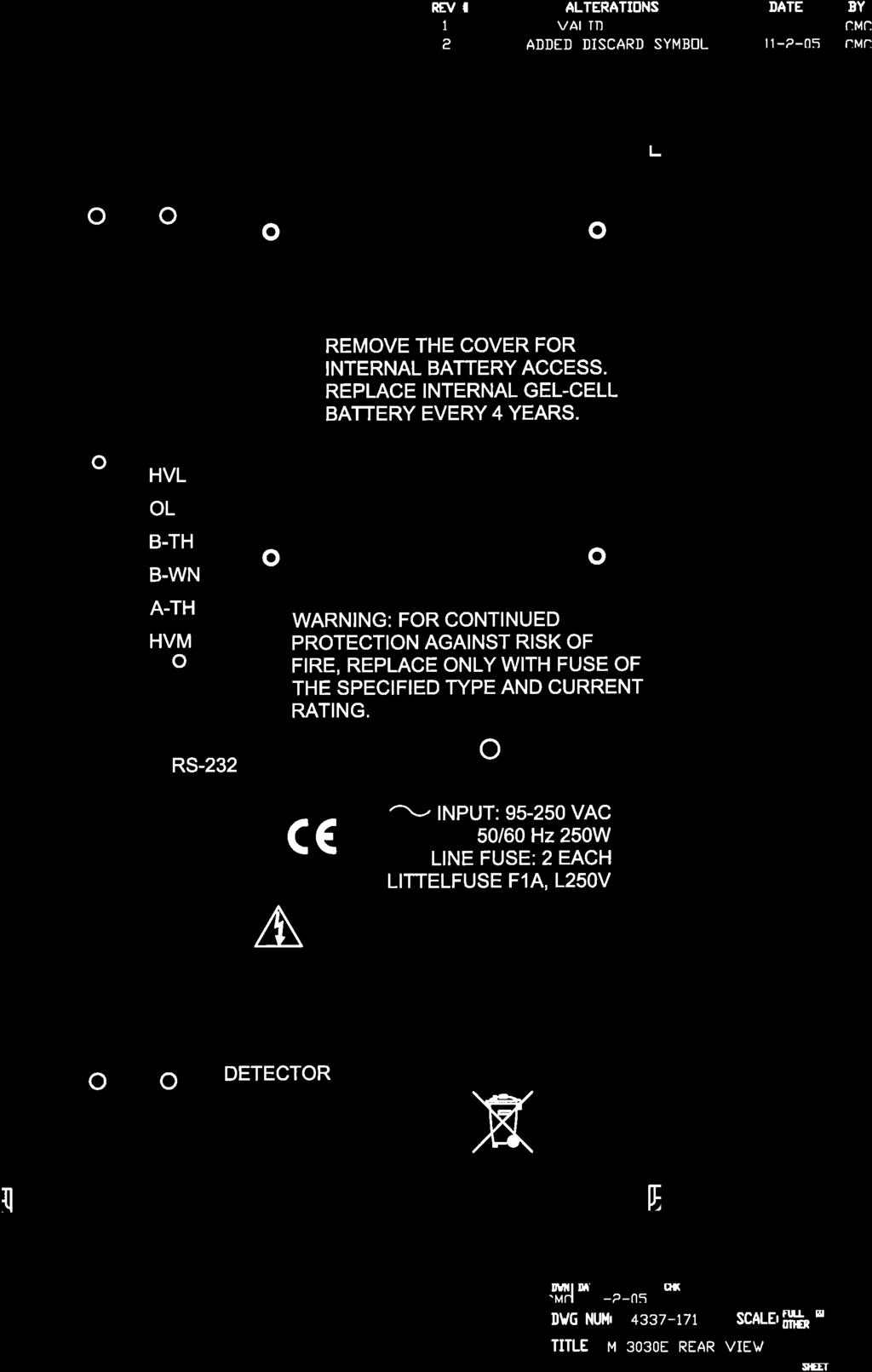
21 Model 3030 & 3030E Series Technical Manual Section 4 ALPHA: A six-digit backlit LCD readout indicates counts received in the alpha counting channel. BETA: A six-digit, backlit LCD readout indicates counts received in the beta counting channel. QC: A red LED indicator illuminates whenever QC is needed. When a valid QC check is performed, the QC indicator turns off. Additionally, the QC indicator is turned off when the QC check feature is disabled (during setup). OL: A red LED indicator illuminates whenever the internal circuitry detects a current overload to the detector. This warning usually indicates an open sample tray or a torn window on the front of the internal detector. Instrument will not count while this indicator is illuminated. CPM: A green LED indicator illuminates whenever CPM mode is established (during setup). DPM: A green LED indicator illuminates whenever DPM mode is established (during setup). αal: A red LED indicator illuminates whenever the alpha count exceeds the alarm level established during setup. βal: A red LED indicator illuminates whenever the beta count exceeds the alarm level established during setup. Back Panel Detector Input Connection (Model 3030E only): a series "C" coaxial connector; other connectors are available upon request RS-232: a 9-pin D-connector for connection to printer or computer CAL: a cover for the calibration potentiometers, which should only be adjusted by trained and authorized personnel during calibration INPUT: line or mains power receptacle and fuse holder. Use of two one-amp, fast-blowing fuses provides protection to the instrument in case of internal electrical failure. Remove the calibration (cal) cover plate to access the following calibration potentiometers: A-TH: a multi-turn potentiometer used to vary the alpha pulse discriminator from 40 to 700 mv, normally set at 120 mv Ludlum Measurements, Inc. Page 9 November 2017
22 Model 3030 & 3030E Series Technical Manual Section 4 B-WN: a multi-turn potentiometer used to vary the upper beta pulse discriminator from BT setting to AT setting, normally set at 50 mv B-TH: a multi-turn potentiometer used to vary the lower beta pulse discriminator from 2 to 15 mv, normally set at 4 mv OL: a multi-turn potentiometer that provides a means to vary the detector current overload set point HVL: a multi-turn potentiometer used to calibrate the digital high voltage HVM: a multi-turn potentiometer used to manually adjust the high voltage when digital control is not desired Internal Controls The following dipswitches and jumpers are located on the amplifier/processor board and are only accessible when the cover is removed. Dipswitch 1: When in the OFF position, the Model 3030 is locked into Scaler mode only. The default position is ON. Dipswitch 2: When in the ON position, the calibration date is disabled. The default position is ON. HV Jumper: When shunt is on the two outside pins, the HV is adjusted manually with the HVM potentiometer. The normal shunt position is on the two inside pins. Ludlum Measurements, Inc. Page 10 November 2017
23 Model 3030 & 3030E Series Technical Manual Section 5 Section 5 Safety Considerations Environmental Conditions for Normal Use Indoor use only No maximum altitude Temperature range of -20 to 50 C (-4 to 122 F) Maximum relative humidity of less than 95% (non-condensing) Mains supply voltage range of Vac, 50/60Hz single phase, 250W Maximum transient voltage of 1500 Vac Installation Category II (Overvoltage Category as defined by IEC ) Pollution Degree 2 (as defined by IEC 664): Normally only nonconductive pollution occurs. Temporary conductivity caused by condensation is to be expected. Cleaning Instructions and Precautions The Model 3030 Alpha-Beta Sample Counter may be cleaned externally with a damp cloth, using only water as the wetting agent. Do not immerse the instrument in any liquid. Observe the following precautions when cleaning: 1. Turn the instrument OFF and disconnect the instrument power cord. 2. Allow the instrument to sit for one minute before cleaning. Ludlum Measurements, Inc. Page 11 November 2017
24 Model 3030 & 3030E Series Technical Manual Section 5 Warning Markings and Symbols Caution! The operator or responsible body is cautioned that the protection provided by the equipment may be impaired if the equipment is used in a manner not specified by Ludlum Measurements, Inc. Caution! Verify instrument voltage input rating before connecting to a power converter. If the wrong power converter is used, the instrument and/or power converter could be damaged. The Model 3030 Alpha-Beta Sample Counter is marked with the following symbols: ALTERNATING CURRENT (AC) (IEC 417, No. 5032) - designates an input receptacle that accommodates a power cord intended for connection to AC voltages. This symbol appears on the back panel. PROTECTIVE CONDUCTOR TERMINAL (per IEC 417, No. 5019) designates the central grounding point for the safety ground. This symbol is visible inside the chassis. CAUTION (per ISO 3864, No. B.3.1) designates hazardous live voltage and risk of electric shock. During normal use, internal components are hazardous live. This instrument must be isolated or disconnected from the hazardous live voltage before accessing the internal components. This symbol appears on the front panel. Note the following precautions: Ludlum Measurements, Inc. Page 12 November 2017
25 Model 3030 & 3030E Series Technical Manual Section 5 Warning! The operator is strongly cautioned to take the following precautions to avoid contact with internal hazardous live parts that are accessible using a tool: 1. Turn the instrument power OFF and disconnect the power cord. 2. Allow the instrument to sit for one minute before accessing internal components. CAUTION, RISK OF ELECTRIC SHOCK (per ISO 3864, No. B.3.6) designates a terminal (connector) that allows connection to a voltage exceeding one kv. Contact with the subject connector while the instrument is on or shortly after turning off may result in electric shock. This symbol appears on the rear panel of the Model 3030E only. The crossed-out wheelie bin symbol notifies the consumer that the product is not to be mixed with unsorted municipal waste when discarding; each material must be separated. The symbol is placed near the AC receptacle. See section 8, Recycling, for further information. Replacement of Main Fuse (Back Panel) Warning! For continued protection against risk of fire, replace only with fuse of the specified type and current rating! Ludlum Measurements, Inc. Page 13 November 2017
26 Model 3030 & 3030E Series Technical Manual Section 6 Section 6 Calibration and Maintenance Calibration The following calibration procedure is applicable to the Model Adjustments are necessary if this procedure is used with the Model 3030E. Where applicable, those changes will be noted with regard to the most common external detector used the Model Other instrument detector combinations are not covered in this manual. Consult the individual detector manual for the needed specifications. A Ludlum Model 500 Pulser or equivalent is required. If the pulser does not have a high-voltage readout, use a high-impedance voltmeter with at least 1000 megohm input resistance to measure the detector voltage. Calibrated sources are also required. Recommended Sources The recommended sources for use with the Model 3030 are plated 239 Pu alpha and 99 Tc beta sources. These sources are 3.2 cm (1.3 in.) disks with an active diameter of 2.5 cm (1 in.). These disks are then mounted in a protective ring with an outside diameter of 4.8 cm (1.9 in.). We feel that this type of source construction protects those vital dpms. The recommended size is as large as possible. Keep in mind that you want good statistics, and to do that you want large numbers in a short amount of time. If you want to count for 60 seconds, than a source size of about 20,000 dpm will generally result in counts (given a 15% 4π efficiency) of 3000 counts. Counting this size source in a tenth of a minute will result in a count of only about 300 above background, and your percentage error will be greater. Increasing the size of the source to 200,000 dpm gives you better statistics, while allowing you to keep the count time short. Calibration Procedure Perform mechanical checks, such as switch function and illumination of digital readouts. Ludlum Measurements, Inc. Page 14 November 2017
27 Model 3030 & 3030E Series Technical Manual Section 6 Remove the outside cover of the Model Measure battery voltage and ensure voltage is 13 volts or greater. Connect the Model 3030 to the computer and load the default settings. Make sure that the jumper on the amplifier/processor board is on the inside two (2) pins. Ensure that both dipswitches are in the ON position. Connect the Model 500 Pulser to the Model 3030 with the appropriate cable. (Computer may stay connected.) Adjust the pulser for 400,000 cpm and adjust the pulse amplitude to 4 mv (negative amplitude). Adjust the beta threshold (B-TH) and beta window (B-WN) for the appropriate set points: B-TH at 4 mv and B-WN at 50 mv. The pulser counts should be detected on the Model 3030 beta display above 4 mv and should shut off above 50 mv. Pulses in the beta channel should be audible. Ensure that the VOLUME control works correctly. Set the Model 500 Pulser amplitude switch to 200 mv. With the Model 500 Pulser set to 120 mv, adjust the alpha threshold (A-TH) control for 120 mv. Pulses in the alpha channel should be audible. Set the HV to 800 Vdc. Using a high-voltage meter, measure the high voltage and adjust the HVL potentiometer on the amplifer/processor board until the high voltage reads 800 Vdc ±2 Vdc. Change the voltage (using the computer) to 500 Vdc and 1500 Vdc. In each case, verify that the high voltage is within ±5% of the correct value. Change the shunt on the jumper (amplifier/processor board) to the manual side (outside two [2] pins from the edge of the board). Adjust the HVM potentiometer to manually adjust the high voltage to 800 Vdc. Place shunt back to the automatic side (inside two [2] pins). Set the LCD count time for 0.1 minute (6 seconds). Adjust the pulser count rate to 400,000 cpm and pulse amplitude to 20 mv. Ludlum Measurements, Inc. Page 15 November 2017
28 Model 3030 & 3030E Series Technical Manual Section 6 Press the COUNT button. When count cycle is complete, multiply the β BETA LCD reading by 10 and confirm that this reading is within ±2% of the incoming count rate. Repeat this step with 200 mv pulses and check the α-alpha LCD reading. The objective of the next steps is to find an operating voltage for the detector that will yield the detector s stated efficiency while not overcounting the background radiation field. The 2π efficiency (Eff) is calculated as: Instrument Count Rate cpm of Source 100% = Eff In addition, cross talk must be considered for determining the optimum operating voltage and is defined as: Alpha cross talk = αsourcecβ - BackCβ αnetcα 100% and Beta cross talk = βsourcecα BackCα βnetcβ 100% where αsourcecβ = α source count in β channel BackCβ = background count in β channel αnetcα = Net α source count in α channel βsourcecα =β source count in α channel BackCα = background count in α channel βnetcβ = Net β source count in β channel For the alpha/beta scintillation detector, applicable 4π efficiencies are: Ludlum Measurements, Inc. Page 16 November 2017
29 Model 3030 & 3030E Series Technical Manual Section 6 27% for 99 Tc, 37% for 239 Pu. Acceptable background count rates (in a 10µR/hr field ) are: alpha: 3 cpm or less beta: typically 50 cpm or less (Model 3030E with : cpm) Acceptable crosstalk values (in a 10µR/hr field) are: alpha crosstalk : 10% or less beta crosstalk : 1% or less. Using the computer interface software, perform a high voltage plateau in 25-volt increments from about 500 to 650 Vdc. Print the results and keep the printout with the calibration certificate. Find the optimum operating voltage, which gives the greatest alpha and beta source efficiencies and acceptable background (cpm), while maintaining acceptable values for crosstalk between channels. Set the unit in DPM mode with efficiencies, background subtract, and crosstalk correction numbers from the high voltage plateau. Set the count time to one minute and print out an MDA chart from the interface software. Ludlum Measurements, Inc. Page 17 November 2017
30 Model 3030 & 3030E Series Technical Manual Section 6 Note: The detector operating voltage must be determined and set before the overload (OL) adjustment is performed. If the detector operating voltage is readjusted, the OL setting must be readjusted. Adjust the OL control to the maximum counterclockwise position. To simulate a light leak, expose the photomultiplier tube (PMT) to light by pulling the tray out. Adjust the OL control until the overload LED just begins to flicker. Confirm that the overload LED turns off when the tray is latched closed. Maintenance Instrument maintenance consists of keeping the instrument clean and periodically checking the battery and calibration. An instrument QC Check should be performed prior to each use by exposing the detector to a known source and confirming the proper reading on each scale. Recalibration should be accomplished after any maintenance or adjustment has been performed on the instrument. Ludlum Measurements recommends recalibration at intervals no greater than one year. Local regulations may have precedence over this recommendation. To maintain the life of the internal battery it is recommended that the instrument be constantly connected to line power with the power switch in the ON position, even when the instrument is not in use. This will keep the internal battery fully charged. When the instrument is used without line power, adequate charge time must be allowed for the internal battery to recharge. If possible, leave the instrument on with line power applied overnight and weekends. At a minimum, allow one hour of charge time for each hour of use. If the battery is inadvertently allowed to fully discharge, and is left in that state, constant charging for 500 hours (three weeks) may be required for battery recovery. Ludlum Measurements, Inc. Page 18 November 2017
31 Model 3030 & 3030E Series Technical Manual Section 6 Note: The ON-OFF switch must be in the ON position to charge the batteries. If the unit is out of service for extended periods of time, charge the battery every six months. It is recommended that the internal gel-cell battery be replaced every four years. Ludlum Measurements, Inc. Page 19 November 2017
, and retrieve the sample data saved to the logging memory.")
32 Model 3030 & 3030E Series Technical Manual Section 7 Section 7 Computer Software T he Model 3030 Control Software allows the user to set all parameters, view QC Check settings, run high voltage plateaus, perform MDA (Minimum Detectable Activity), and retrieve the sample data saved to the logging memory. Certain parameters can be protected by a password to prevent changes that could affect the calibration of the instrument. When the software is started, a dialogue is displayed allowing the user to manually select the Comm port or to have the software select it automatically. The software will only search Comm ports After the Model 3030 is found, the parameters are downloaded from the instrument and the main screen is displayed. The main screen consists of a tabbed interface separating the various functions and include General Settings, QC Check, HV Plateau, MDA Calculation, and Data Logging. Ludlum Measurements, Inc. Page 20 November 2017


33 Model 3030 & 3030E Series Technical Manual Section 7 The following parameters require a password: Calibration Date, Date, Time, High Voltage, Background Subtract On/Off, Alpha Background Subtract, Beta Background Subtract, Alpha Efficiency, Beta Efficiency, Crosstalk On/Off, Alpha Crosstalk, and Beta Crosstalk. Running an HV Plateau is also password protected. Password operation can be enabled in the Parameters menu. Selecting the "Password Protect" menu item will enable password protection. A checkmark next to this menu item will indicate if password protection is on or off. The password is required to change this. The default password is blank until it is changed by the user using the Change Password menu item. The password can contain the following characters: a-z, A-Z, 0-1,!@#$%^&*() and cannot exceed eight characters in length. Ludlum Measurements, Inc. Page 21 November 2017


34 Model 3030 & 3030E Series Technical Manual Section 7 The user is prompted for the password when clicking in the Update button after changing any of the password protected parameters. If the password given is correct, the parameters are changed and the instrument is updated. If the password is incorrect and the user cancels the password prompt, the previous values for the parameters are restored, with no parameters sent to the instrument. Clicking in the Start button under the HV Plateau tab will prompt the user for the password. The password will not be asked for again until a different tab is selected to allow the user to run multiple plateaus without having to enter the password every time. Parameters The Update button at the bottom of the window will save all changes to the instrument. File Menu/Load Defaults: This menu item loads the file, default.cfg, and saves the settings to the instrument. Parameters/Update (Ctrl-U): This menu item is the same as clicking on the Update button. Parameters/Load from File (Ctrl-O): This menu item loads in settings from a user-defined text file. Parameters/Save to File (Ctrl-S): This menu item will save the current settings to a user-defined file. Parameters/Reload All Data (Ctrl-R): This menu item will reload all data from the instrument. Parameters/Print Parameters (Ctrl-P): This menu item will print out a report of all parameters to a printer. Parameters/Password Protect: When this is checked, certain functions require a password. Ludlum Measurements, Inc. Page 22 November 2017
35 Model 3030 & 3030E Series Technical Manual Section 7 Parameters/Change password. Password: This selection changes the current Headers 1 6: These are six user-defined fields to place general information. These are limited to 15 characters. Calibration Due Date: This date is checked when instrument is turned on. If current date is past this date, OUTCAL is displayed on the instrument. Setting Dipswitch 2 to the ON position will disable this feature Date/Time: This is the current date and time from the last time data was read from the instrument. User Defined Time (min): In addition to the seven preset count times, there is a user-defined count time that can be set from the PC. This is the count time that will be used when the instrument is switched to the PC position. Alpha, Beta, Alpha + Beta Alarms: These are the alarm settings. A value of will disable the alarm. If the unit is in CPM, the alarms are in CPM. If the instrument is in DPM, the alarms are in DPM. It is up to the user to make sure that the alarms are set accordingly to the count mode. High Voltage: This field displays the current high-voltage setting. The high voltage may be adjusted from 0 to 2000 Vdc. Loss of Count Timer: If the detector receives no counts on the beta channel after the time expires, the display will show LOC FAIL and will not operate until reset. This timer is reset whenever a count is received. Count Mode: The model 3030 can display the readings in raw scaler counts, CPM, or DPM. If dipswitch 1 is OFF, the unit is always in scaler mode. The Ludlum Model 3030 can operate as a traditional radiation scaler, displaying measurements in terms of CPM (counts per minute). It can also be programmed to automatically adjust and display the measurements in DPM (disintegrations per minute). By knowing what the efficiency is for alpha and beta particles, the Model 3030 is able to divide measurements by the known efficiency and display in DPM. The DPM mode may be easier for users, since many regulations and limits are expressed in terms of DPM. In raw scaler mode, the count obtained is the actual counts received during that count time. In CPM mode, the counts are adjusted for the count time. In DPM mode, the counts are adjusted for count time and efficiency. For example: Count Time = 0.1 minutes (6 seconds) Ludlum Measurements, Inc. Page 23 November 2017
36 Model 3030 & 3030E Series Technical Manual Section 7 Efficiency = 25% Input = 1000 DPM CPM = 250 counts per minute (no background subtract or crosstalk calculations) DPM = 400 disintegrations per minute (no background subtract or crosstalk calculations) Alpha/Beta Efficiency: These values are only available when unit is in DPM count mode. This is used to calculate the DPM reading and is expressed as a percent. The QC mode has a function to update the efficiency with values calculated from the QC check. Activate Background Subtract: This is only available when count mode is CPM or DPM. It turns on/off the background subtract and will subtract the background from each channel and display the net count. Alpha/Beta Background Subtract: These values will be subtracted while the instrument is counting. For example, in CPM mode with an input of 2000 CPM and a background subtract value of 1000, the reading will display The QC mode has a function to update the background subtract with values calculated from the QC check. Activate Crosstalk Correction: This is only available when count mode is CPM or DPM. This control turns on/off the crosstalk correction. % Alpha to Beta Crosstalk: This is the percent of alpha counts that are seen by the beta channel. Setting this number to 2% subtracts 2% of the received alpha counts from the beta channel. % Beta to Alpha crosstalk: This is the percent of beta counts that are seen by the alpha channel. Setting this number to 2% subtracts 2% of the received beta counts from the alpha channel. Show Parameters during power-up: When enabled, the following are displayed to the LCD display during power up: firmware version, date, time, high voltage, user-defined count time, and alarms. Ludlum Measurements, Inc. Page 24 November 2017

37 Model 3030 & 3030E Series Technical Manual Section 7 QC Check The Ludlum Model 3030 has a QC Check function that allows the user to determine whether the instrument is operating within predetermined limits. This function is optional and does not have to be enabled. There is also an option to update the background every 24 hours. This background update does not validate the received reading with any of the limits set on this screen. It simply takes a background count and stores that reading in the instrument. When the QC check is enabled, every day the user must perform the QC check procedure and receive acceptable values in order to utilize the instrument for normal use. After 24 hours, the instrument will light the red indicator marked QC, and not allow normal use until the next QC check. The predetermined limits are: 1. The instrument counts a specific alpha source with a known activity and receives a specified standard efficiency, plus or minus a specified percentage. 2. The instrument counts a specific beta source with a known activity and receives a specified standard efficiency, plus or minus a specified percentage. 3. The instrument counts background (no source inside the tray) and receives results that are within the upper and lower limits specified. Ludlum Measurements, Inc. Page 25 November 2017
38 Model 3030 & 3030E Series Technical Manual Section 7 QC Off/Normal QC/Background Update Only/Manual QC Only: If enabled, 24 hours after the last QC check, the QC LED turns on and a QC check must be run before the normal operation can resume. The Normal QC check takes both an alpha and beta source count and a background count. The Background Update Only takes only background counts and replaces the current background subtract values with the new values. In the Background Update Only mode the display shows the counts in CPM with one decimal place. Manual mode allows the QC button to start a QC test but does not automatically require one after 24 hours. Manual QC option only available with firmware 39013N31 or higher. If the QC mode is disabled then a QC test cannot be started with the QC button. Update Efficiency: If enabled, the efficiencies calculated during the QC check will replace the efficiencies used for the DPM calculation. This option is only available in the Normal QC check mode. Update Background Subtract: If enabled, the background readings received during the QC check will replace the current background subtract values. This option is only available in the Normal and Background Only QC check modes. Override Count Time: If enabled, the count times set by the count time switch on the front of the instrument are overridden using the values in the alpha, beta, and background QC count times. Last QC Performed: This is the last date and time a successful QC check was performed. Last Alpha/Beta Efficiency: The last time a QC check was run, this was the computed efficiency. Standard Alpha/Beta Efficiency: These are the values that the QC check will use to determine pass/fail. If the calculated efficiency is outside the Standard Efficiency by the Allowable QC Efficiency %, the QC will fail. Allowable QC Efficiency ± %: This is the range for how close the computed efficiency must be to the standard. A standard of 25% with an allowable range of 5% specifies that to pass the QC check, the efficiency must be in the range of 20% to 30% to pass. Source Size: The DPM value of the source size is saved to the instrument and is used to determine the efficiency during a QC check. Ludlum Measurements, Inc. Page 26 November 2017
39 Model 3030 & 3030E Series Technical Manual Section 7 Alpha QC Source Count Time (min): This is the alpha source count time in minutes used when the Override Count Time function is enabled. Beta QC Source Count Time (min): This is the beta source count time in minutes used when the Override Count Time function is enabled. Background QC Count Time (min): This is the background count time in minutes used when the Override Count Time function is enabled. Alpha/Beta Upper & Lower Limits: These determine what range is acceptable for the background during a QC check. If the background does not fall within these values, the QC check will fail. Alpha/Beta Upper & Lower Limits: These determine what range is acceptable for the background during a QC check. If the background does not fall within these values, the QC check will fail. STEPS FOR PERFORMING A QC CHECK 1. To enable the QC mode, click on the box marked Normal QC in the tab marked QC Settings. 2. Press the button marked Reload Last Values at the bottom of the screen to see the last values calculated during the last HV Plateau. The data shown include the Last QC Performed, the Last Alpha Efficiency, the Last Beta Efficiency, the Last Alpha Background, and the Last Beta Background. These numbers are shown for reference ONLY. The QC check predetermined limits must be chosen and input by the user. 3. Enter values for the Standard Alpha Efficiency and the Standard Beta Efficiency. The values input here should reflect the average efficiency with the given sources. After entering the values, press the Update button. 4. Enter values for the Allowable QC Efficiency. These percentage values entered allow the instrument to accept efficiencies that are somewhat higher and lower than the standard efficiency. For example, if the standard alpha efficiency is 25% and the allowable QC efficiency is 5%, the acceptable alpha efficiency will be from 20% to 30%. After entering the values, press the Update button. 5. Enter the Alpha Source Size and Beta Source Size of the sources to be used during the QC check. It is preferred to use the DPM or µci column wherever possible. Conversion from Ludlum Measurements, Inc. Page 27 November 2017
40 Model 3030 & 3030E Series Technical Manual Section 7 CPM to DPM using a factor of 2 may not be correct, depending on isotope and source material. Note that these source sizes are completely independent of the source sizes used in the HV plateau. After entering the values, press the Update button. Enter in upper and lower background limits for both alpha and beta background. Since alpha background is usually very low, it is acceptable to use a lower limit of 0. After entering the values, press the Update button. To start a QC check: 1. Press the QC CHECK button on the front of the Model The Model 3030 does not need to be connected to a computer for the QC check to function. 2. If the Normal QC mode is selected, the upper LCD should flash ALPHA. Unlatch the tray and insert the alpha source. Close and latch the tray. 3. Press the COUNT button to start the alpha count. At the end of the count, the LCD will flash between displaying the final readings and ALPHA. If the QC Check fails, the instrument should be taken out of service until it can be repaired. 4. Unlatch the tray and remove the alpha source. Insert the beta source and close and latch the tray. 5. Press the COUNT button to advance to the beta step. The lower LCD should now flash BETA. 6. Press the COUNT button to start the beta count. At the end of the count the LCD will flash between displaying the final readings and BETA. If the QC check fails, the instrument should be taken out of service until it can be repaired. 7. Unlatch the tray and remove the beta source. Close and latch the tray. 8. Press the COUNT button to advance to the background count. Both displays should flash BAC. 9. Press the COUNT button to start the background count. At the end of the count, the LCD will flash between the readings and BAC. If the QC check fails, the instrument should be taken out of service until it can be repaired. Ludlum Measurements, Inc. Page 28 November 2017
 plateau is normally run at calibration time in order to set the proper HV and to determine the operating efficiencies.")
41 Model 3030 & 3030E Series Technical Manual Section Press the COUNT button to exit the QC check mode. HV Plateau A high-voltage (HV) plateau is normally run at calibration time in order to set the proper HV and to determine the operating efficiencies. This routine is provided to automate the plateau procedure and simplify the calculations. This screen allows you to enter the starting and ending value, the voltage increment, and the source size. The background count is always one minute. The data may be saved in a text file or printed to a printer. The plateau order can be changed from Alpha, Beta, Background to Beta, Alpha, Background. STEPS FOR PERFORMING A HIGH VOLTAGE PLATEAU 1. Turn the Model 3030 on and connect to a computer by way of a serial port with supplied cable. 2. Run the Model 3030 control software. Software will automatically detect the instrument and download all parameters. 3. When all the parameters have been downloaded, click on the tab marked HV Plateau at the top of the window. Ludlum Measurements, Inc. Page 29 November 2017
42 Model 3030 & 3030E Series Technical Manual Section 7 4. Enter the Starting High Voltage and the Ending High Voltage. These parameters define where the plateau will start and end. 5. Enter the High Voltage Step. This parameter determines the increment between steps in the plateau. 6. Enter the Alpha Source Size and Beta Source Size. There are three fields for each channel corresponding to CPM, DPM, and µci. The user can enter the source size in any field, and the other fields will automatically show the converted value. It is preferred to use the DPM or µci column wherever possible. Conversion from CPM to DPM using a factor of 2 may not be correct depending on isotope and source material. Under the ISOTOPE fields, enter the isotope label for the alpha and beta source. 7. Verify the current count time. The Model 3030 has seven preset time values and a user-definable PC time set by the computer. The PC time is defined in the tab marked General Settings. Enter in the needed time and press Update. If a different time is required, change the time by using the knob on the front of the instrument and click the Read button to refresh the count time on screen. The background count time is always one minute. 8. Press the Start button to start the plateau. There is a prompt to insert the alpha source. The Model 3030 will record readings at each high voltage as determined above. When the alpha plateau is completed, you are prompted to insert the beta source. Again, the Model 3030 will record readings at each high voltage. After the beta plateau is complete, you are prompted to remove the beta source. Background counts are then taken. The grid contains the following columns: 1. Alpha source (beta counts shown in parenthesis) 2. Beta source (alpha counts shown in parenthesis) 3. Alpha background in cpm 4. Beta background in cpm 5. % alpha efficiency (4π) 6. % beta efficiency (4π) Ludlum Measurements, Inc. Page 30 November 2017

43 Model 3030 & 3030E Series Technical Manual Section 7 7. % alpha to beta crosstalk 8. % beta to alpha crosstalk 9. After the plateau is complete, you can either save the plateau to an ASCII text file or print the results for later reference. 10. You may choose the operating voltage according to your own standards. Ludlum Measurements current standards, which may or may not be appropriate for your use, are listed below: (a) 99 Tc efficiency (4π) greater than or equal to 27% (b) 239 Pu efficiency (4π) greater than or equal to 37% (c) Alpha crosstalk in beta channel less than or equal to 10% (d) Beta crosstalk in alpha channel less than or equal to 1% (e) Beta background is less than or equal to 50 cpm (f) Alpha background is less than or equal to 3 cpm 11. By double-clicking on a row after the plateau has completed, the user may automatically update the efficiencies, background subtract, and crosstalk values, or the user can manually enter in the values to update the instrument. Manual Entry: 12. Enter the selected operating voltage in the field marked High Voltage (Vdc) and click Update. This action stores the chosen operating voltage inside the Model Click on DPM under the Count Mode area to select DPM mode. Ludlum Measurements, Inc. Page 31 November 2017

44 Model 3030 & 3030E Series Technical Manual Section Enter in the alpha and beta efficiencies as 4π efficiencies and click Update. 15. You may also choose to utilize the Background Subtract function by entering values to subtract the known constant background from each measurement. The values may be chosen from the data gathered above during the plateau. When used, the value entered is subtracted prior to the conversion to DPM. 16. You may also choose to utilize the Crosstalk Correction function by entering values to correct each measurement for crosstalk. The values may be chosen from the data gathered above during the plateau. When used, the crosstalk correction is applied to measurements after background subtraction (if active) and before the DPM conversion (if active). MDA Calculations This screen shows the calculated MDA values for all count times based on the current background and efficiency values. The confidence level may be set at 90%, 95%, or 99%. This screen is only available when the instrument is in DPM mode. The values are preset according to the current instrument settings but may be changed here. The data may also be printed to a printer. Ludlum Measurements, Inc. Page 32 November 2017

45 Model 3030 & 3030E Series Technical Manual Section 7 Data Logging The Model 3030 can store 600 samples in its data logging memory. The following fields are stored with each sample: time, date, alpha reading, beta reading, count time, count mode, and user-defined comment. Recycle On: This will activate the recycle function. As soon as the count completes, another one is started automatically. Logging Mode: The choices are either Off, Log All, or Log QC only. This will activate the saving of samples to the instrument s non-volatile memory. Printer Mode On: When activated, the instrument will output the count data to the serial port. No handshaking is active. A serial printer may be connected to display the data. The date, time, alpha reading, beta reading, count mode, and count time is output. The count mode is indicated by a single letter: C = cpm, D = dpm, S = Scaler. Get Samples: This button reads all sample data from the instrument. Clear Samples: This button clears the instrument of all samples in memory. Save Samples: This allows saving the sample data to a user-defined file. The data is saved in a comma delimited (*.csv) file to allow for importing into other applications. Ludlum Measurements, Inc. Page 33 November 2017
46 Model 3030 & 3030E Series Technical Manual Section 7 Print Samples: Selecting this option prints the sample data to a printer. RS-232 Communication The Model 3030 communicates by way of an RS-232 interface. The RS-232 port operates at 9600 baud, 8 data bits, 1 stop bit, no parity, and hardware (RTS/CTS) flow control. A standard RS-232 cable with straight-through connections is required. Following is information for pin-outs of the RS-232 Connector/Cable: M3030 PC (9-Pin) 2 TXD RXD 2 3 RXD TXD 3 5 GND GND 5 7 CTS RTS 7 8 RTS CTS 8 The Model 3030 uses the line-feed character [LF] to terminate commands. It is acceptable to terminate commands with a carriage return and a line feed character. All messages received from the Model 3030 are terminated with a carriage return and line feed character. The commands are not case sensitive. Any command not recognized will return "ERROR-xx" where xx is the first two characters of the unknown command. [LF] = line feed character (ASCII value 10) [CR] = carriage return character (ASCII value 13) COMMANDS Bn Background Subtract Status Sets background subtract ON/OFF or return background subtract status, where n: is a value of 0, 1, or 2. 0 = Sets background subtract OFF. 1 = Sets background subtract ON. 2 = Returns status. Ludlum Measurements, Inc. Page 34 November 2017
47 Model 3030 & 3030E Series Technical Manual Section 7 Cn - Count Performs various count functions. The count time is determined by the positing of the COUNT TIME SWITCH on the front panel unless otherwise noted. See command RR for the format of the count results. 1 = Start a count. 2 = Stop a count in progress. 3 = Clear alarms. 4 = Start a count and automatically return the results. 5 = Start a one-minute count and automatically return the results. Dn Display Mode The display can be set to show count data as raw scaler counters, counts per minute (CPM), and disintegrations per minute (DPM). 0 = Set display mode to scaler. 1 = Set display mode to CPM. 2 = Set display Mode to DPM. 3 = Return display mode (SCA, CPM, or DPM). F Firmware Returns a string containing the firmware version number. Ln Logging Mode Sets how samples are logged to internal memory. 0 = Turn logging OFF. 1 = Turn Logging ON. 2 = Log only QC checks. 3 = Return logging mode (OFF, ON, or QC). Pn Sets printer mode On/Off. 0 = Turn printing OFF. 1 = Turn printing ON. 2 = Return printing mode (OFF, ON). Qx Sets quick power-on mode. The Model 3030 may be configured to display certain parameters during power-up. Ludlum Measurements, Inc. Page 35 November 2017
48 Model 3030 & 3030E Series Technical Manual Section 7 0 = Show parameters OFF. 1 = Show parameters ON. 2 = Return power-up mode (OFF, ON). RA Read Next Sample Number Reads the next sample number. Subtracts one from this number to get the total number of samples logged. Returns nnnn. RBn Read Background Subtract Reads the alpha or beta background subtract value. The value returned must be divided by 10 to get the correct value. Returns nnnnnn. 1 = Read alpha background subtract. 2 = Read beta background subtract. RC Read Calibration Due Date Reads the calibration due date. Returns MMDDYYYY. RD Read Current Date and time Reads the current date and time. Returns HH:MM:SS MM/DD/YYYY. REn Read Efficiency Reads the alpha or beta percent efficiency. The value returned must be divided by 10 to get the correct value. Returns nnn. 1 = Read alpha percent efficiency. 2 = Read beta percent efficiency. RHn Read Header Reads the 15-character, user-definable header where n is a value from 1 to 6. Returns xxxxxxxxxxxxxxx. RL Read Loss of Count Timer Reads the loss of count timer value in seconds. Returns two lines. Line 1 contains the count time as nnnnn.n. Line 2 returns BETA if the loss of count timer has expired. Otherwise, OK is returned. RNn Read MDA Reads the Minimum Detectable Activity (MDA). Returns nnnnnn. Ludlum Measurements, Inc. Page 36 November 2017
49 Model 3030 & 3030E Series Technical Manual Section 7 1 = Read alpha ratemeter MDA. 2 = Read beta ratemeter MDA. 3 = Read alpha scaler MDA. 4 = Read beta scaler MDA. RP Read the PC Time Reads the PC or user-defined count time in seconds. The PC time is used when the COUNT TIME SWITCH on the front panel is set to PC. Returns nnnnn.n. RQn Reads the specified QC parameter. 01 = Read QC enabled status. Returns ON or OFF. 02 = Read current alpha efficiency %. Returns nn. 03 = Read current beta efficiency %. Returns nn. 04 = Read standard alpha efficiency %. Returns nn. 05 = Read standard beta efficiency %. Returns nn. 06 = Read alpha source size (cpm). Returns nnnnnn. 07 = Read beta source size (cpm). Returns nnnnnn. 08 = Read alpha efficiency limit %. Returns nn. 09 = Read beta efficiency limit %. Returns nn. 10 = Read alpha background upper limit (cpm). Returns nnnnnn. 11 = Read alpha background lower limit (cpm). Returns nnnnnn. 12 = Read beta background upper limit (cpm). Returns nnnnnn. 13 = Read beta background lower limit (cpm). Returns nnnnnn. 14 = Read last QC date. Returns MM/DD/YYYY. 15 = Read alpha background (cpm). Returns nnnnnn. 16 = Read beta background (cpm). Returns nnnnnn. 17 = Read last QC time. Returns HH:MM. 18 = Read QC Mode. Returns NOR, BKG, or MAN. 19 = Read QC Update Mode. Returns OFF, ON, EFF, or SUB. 20 = Read alpha source count time (secs). Returns nnnnn.n. 21 = Read beta source count time (secs). Returns nnnnn.n. 22 = Read background count time (secs). Returns nnnnn.n. 23 = Read QC override status. Returns OFF or ON. RR Read Count Reads the current alpha and beta counts. Returns HH:MM MM/DD/YY aaaaaa bbbbbb x tttt.t. aaaaaa = alpha count bbbbbb = beta count x = S (scaler), C (cpm), and D (dpm) Ludlum Measurements, Inc. Page 37 November 2017
50 Model 3030 & 3030E Series Technical Manual Section 7 tttt.t = count time in minutes (If count is in progress, this value shows count time remaining.) RS Read Samples Reads all logged samples from memory. While reading samples, the audio is stopped and the displays show a scrolling series of dashes along with the sample number. A "$" marks the end of the samples. Returns: ssss MM/DD/YY HH:MM:SS aaaaaa bbbbbb ttttt.t x cccccccccc[cr][lf] - 59 bytes $[CR][LF] - 3 bytes ssss = sample number aaaaaa = alpha scaler bbbbbb = beta scaler x = S (Scaler), C (cpm), and D (dpm) ttttt.t = count time in seconds cccccccccc = user defined comment RT Read Current Count Time Reads the current count time in seconds. Returns nnnnn.n. RU Read Comment Reads the user-defined, 10-character comment field. Returns xxxxxxxxxx. RV Read High Voltage Reads the high voltage set point. Returns nnnn. RXn Read the Crosstalk Reads the beta-to-alpha or alpha-to-beta crosstalk. The value must be divided by 10 to get the correct value. Returns nnn. 1 = Read beta-to-alpha crosstalk. 2 = Read alpha-to-beta crosstalk. RY Read Recycle Mode Status Reads the status of the recycle mode. Returns OFF or ON. Rn Read the Alarm Set Points Reads the specified alarm set point. Returns nnnnnn. Ludlum Measurements, Inc. Page 38 November 2017
51 Model 3030 & 3030E Series Technical Manual Section 7 1 = Read alpha alarm set point. 2 = Read beta alarm set point. 3 = Read alpha + beta alarm set point. Xn Set Crosstalk Mode Sets crosstalk ON/OFF or return crosstalk status, where n is a value of 0, 1, or 2. 0 = Sets crosstalk OFF. 1 = Sets crosstalk ON. 2 = Returns status. SBnxxxxxx Set Background Subtract Sets the alpha or beta background subtract. 1 = Set alpha background subtract. 2 = Set beta background subtract. SCmmddyyyy Set Calibration Date Sets the calibration due date. SDmmddyyyyz Set Date Sets the date on the read time clock. The z is the value of the year Mod 4. SEnxxx Set Efficiency Sets the alpha or beta efficiency. The efficiency must be multiplied by 10 before sending. 1 = Set alpha efficiency. 2 = Set beta efficiency. SHnxxxxxxxxxxxxxxx Set Header Sets a user-defined header. There are six headers accessed 1-6. Each header is 15 characters long. SLyyyyy.y Set Loss of Count Timer Sets the loss of count timer in seconds. The max is seconds. SNnyyyyyy Set MDA Sets the alpha and beta MDA. Ludlum Measurements, Inc. Page 39 November 2017
52 Model 3030 & 3030E Series Technical Manual Section 7 1 = Set alpha MDA. 2 = Set beta MDA. SPxxxxx.x Sets the user-defined count time when the COUNT TIME SWITCH is in the PC position. The max is seconds. SQnn Set QC parameters Sets the specified QC parameter. 01 = Set QC enabled status. 0 = OFF, 1 = ON. 04 = Set standard alpha efficiency %. Format ##. 05 = Set standard beta efficiency %. Format ##. 06 = Set alpha source size (cpm). Format ######. 07 = Set beta source size (cpm). Format ######. 08 = Set alpha efficiency limit %. Format ##. 09 = Set beta efficiency limit %. Format ##. 10 = Set alpha background upper limit (cpm). Format ######. 11 = Set alpha background lower limit (cpm). Format ######. 12 = Set beta background upper limit (cpm). Format ######. 13 = Set beta background lower limit (cpm). Format ######. 17 = Set last QC time. Format HHMM. 18 = Set QC Mode. 0 = NOR, 1 = BKG, 2=MAN. 19 = Set QC Update Mode. 0 = OFF, 1 = ON, 2 = EFF, 3 = SUB. 20 = Set alpha source count time (secs). Format #####.#. 21 = Set beta source count time (secs). Format #####.#. 22 = Set background count time (secs). Format #####.#. 23 = Set QC override status. 0 = OFF, 1 = ON. SR Reset All Samples Clears all logged samples from memory. SThhmm Set Time Sets the real-time clock. Seconds are always started at 00. SUxxxxxxxxxx Set Command Sets a user-defined, 10-character comment that is saved with the logged samples. SVxxxx Set High Voltage Sets high voltage from 0000 to 2000 volts. Ludlum Measurements, Inc. Page 40 November 2017
53 Model 3030 & 3030E Series Technical Manual Section 7 SXnyyy Set Crosstalk Sets the beta-to-alpha or alpha-to-beta crosstalk. The crosstalk must be multiplied by 10 before sending. 1 = Set beta to alpha crosstalk. 2 = Set alpha to beta crosstalk. SYn Set Recycle Mode Set recycle mode. If recycle mode it ON, after a count completes, another one will be started automatically. 0 = Set recycle mode OFF. 2 = Set recycle mode ON. Snxxxxxx Set Alarm Set the specified alarm set point. 1 = Set alpha alarm set point. 2 = Set beta alarm set point. 3 = Set alpha + beta alarm set point. Sample Printouts Ludlum Measurements, Inc. Model 3030 Plateau Data /15/ :05:07 AM Header 1: John Q Public Header 2: Serial# Header 3: Site:Building 1 Header 4: Room 7 EastWall Header 5: More Comments? Header 6: More Comments? Calibration Due Date: 12/31/2010 Model 3030 Date: 01/15/2001 Model 3030 Time: 09:00:08 User PC Time: Alpha Isotope: 239 Pu Alpha Source Size (cpm): Alpha Source Size (dpm): Alpha Source Size (µci): Beta Isotope: 99 Tc Beta Source Size (cpm): 9350 Beta Source Size (dpm): Beta Source Size (µci): Ludlum Measurements, Inc. Page 41 November 2017
54 Model 3030 & 3030E Series Technical Manual Section 7 Starting High Voltage: 750 Starting High Voltage: 950 High Voltage Increment: 25 Source Count Time (min): Background Count Time (min): 1.0 Plateau Count Mode: SCALER ALPHA BETA HV Source (Beta) Background Eff CrossTalk Source (Alpha) Background Eff Crosstalk (764) % 6.4% 3868 (3) % 0.1% (533) % 4.3% 4128 (1) % 0.0% (469) % 3.6% 4523 (0) % 0.0% (377) % 2.8% 4753 (4) % 0.1% (322) % 2.3% 4969 (2) % 0.0% (335) % 2.1% 5009 (4) % 0.1% (338) % 1.4% 5066 (1) % 0.0% (390) % 0.0% 5285 (0) % 0.0% (493) % 0.0% 5501 (1) % 0.0% Ludlum Measurements, Inc. Model 3030 MDA Calculation Data /15/ :05:07 AM Alpha Background(cpm): 1 Beta Background (cpm): 44 Alpha Efficiency %: 15 Beta Efficiency %: 25 Confidence Level: 90% Count Time Alpha MDA(dpm) Beta MDA(dpm) Ludlum Measurements, Inc. Model 3030 Sample Data /15/ :05:07 AM Sample # Date Time Alpha Count Beta Count Count Time Type Comment /15/ :01: s /15/ :02: s /15/ :03: s /15/ :04: s /17/ :00: s QC Check /17/ :02: s /17/ :03: s /17/ :04: s /18/ :00: s QC Check /19/ :00: s Bkgnd Upd Ludlum Measurements, Inc. Page 42 November 2017
55 Model 3030 & 3030E Series Technical Manual Section 7 Software License Agreement Ludlum Measurements, Inc. Page 43 November 2017
56 Model 3030 & 3030E Series Technical Manual Section 7 Ludlum Measurements, Inc. Page 44 November 2017
57 Model 3030 & 3030E Series Technical Manual Section 7 Ludlum Measurements, Inc. Page 45 November 2017
58 Model 3030 & 3030E Series Technical Manual Section 8 Section 8 Recycling L udlum Measurements, Inc. supports the recycling of the electronic products it produces for the purpose of protecting the environment and to comply with all regional, national, and international agencies that promote economically and environmentally sustainable recycling systems. To this end, Ludlum Measurements, Inc. strives to supply the consumer of its goods with information regarding reuse and recycling of the many different types of materials used in its products. With many different agencies public and private involved in this pursuit, it becomes evident that a myriad of methods can be used in the process of recycling. Therefore, Ludlum Measurements, Inc. does not suggest one particular method over another, but simply desires to inform its consumers of the range of recyclable materials present in its products, so that the user will have flexibility in following all local and federal laws. The following types of recyclable materials are present in Ludlum Measurements, Inc. electronic products and should be recycled separately. The list is not all-inclusive, nor does it suggest that all materials are present in each piece of equipment: Batteries, Glass, Aluminum, and Stainless Steel Circuit Boards, Plastics, Liquid Crystal Display (LCD) Ludlum Measurements, Inc. products, which have been placed on the market after August 13, 2005, have been labeled with a symbol recognized internationally as the crossed-out wheelie bin. This notifies the consumer that the product is not to be mixed with unsorted municipal waste when discarding; each material must be separated. The symbol will be placed near the AC receptacle, except for portable equipment where it will be placed on the battery lid. The symbol appears as such: Ludlum Measurements, Inc. Page 46 November 2017
59 Model 3030 & 3030E Series Technical Manual Section 9 Section 9 Parts List Reference Description Part Number Model 3030 & Model 3030E Alpha-Beta Sample Counters UNIT Completely Assembled Model 3030 Alpha-Beta Sample Counter UNIT Completely Assembled Model 3030E Alpha-Beta Sample Counter Amplifier / Processor Board, Drawing BOARD Completely Assembled Amplifier/Processor Board CRYSTALS CAPACITORS Y1 Micro KHz Y2 Micro MHz C1-C4 1uF, 35V C5 10uF, 10V C6 10pF, 100V C7-C8 27pF, 100V C9-C10 1uF, 35V C u1F, 100V C12 100pF, 100V C uF, 100V C14 0.1uF, 50V C15 47pF, 100V C16 10uF, 25V C17 47pF, 100V C uF, 100V C uF, 50V C20 47pF, 100V C21 0.1uF, 50V C22 10pF, 100V C23 47pF, 100V C24 100pF, 3KV Ludlum Measurements, Inc. Page 47 November 2017
60 Model 3030 & 3030E Series Technical Manual Section 9 Reference Description Part Number C25 47pF, 100V C uF, 50V C27 47pF, 100V C28 100pF, 3KV C uF, 3KV C30 0.1uF, 50V C31-C uF, 1KV C uF, 3KV C35-C uF, 3KV C37 100pF, 3KV C38 1uF, 35V C39 68uF, 6.3V C40 47uF, 10V C41-C42 0.1uF, 50V TRANSISTORS INTEGRATED CIRCUITS DIODES Q1 2N7002L Q2 MJD210RL Q3 2N7002L Q4 MJD210RL Q5 MMBT3904LT U1 MAX232D U2 MAX810LEUR U3 PCF8593TD U4 N87C51FC U5-U6 24C65ISM U7 LM285MX U8 LTC1257IS U9 CD74HC4538M U10 TLC372ID U11 CA3096M U12 TLC372ID U13 CD74HC4538M U14 TLC27M7ID CR1-CR4 MMBD914LT CR5 MMBD7000LT CR6 MMBD914LT CR7-CR11 GI Ludlum Measurements, Inc. Page 48 November 2017
61 Model 3030 & 3030E Series Technical Manual Section 9 Reference Description Part Number POTENTIOMETERS RESISTORS R9 1 MEG TRIMMER R11 100K TRIMMER R12 1 MEG TRIMMER R18 10K TRIMMER R25 1 MEG TRIMMER R32 1 MEG TRIMMER R1 1K, 1/8W, 1% R2-R7 22.1K, 1/8W, 1% R8 2.21K, 1/8W, 1% R OHM, 1/8W, 1% R K, 1/8W, 1% R14 1.5K, 1/8W, 1% R K 1/8W, 1% R16 10K, 1/8W, 1% R K, 1/8W, 1% R19-R20 100K, 1/8W, 1% R K, 1/8W, 1% R OHM, 1/8W, 1% R K, 1/8W, 1% R24 392K, 1/8W, 1% R K, 1/8W, 1% R27-R28 10K, 1/8W, 1% R K, 1/8W, 1% R30 100K, 1/8W, 1% R31 1MEG, 1/8W, 1% R33 10K, 1/8W, 1% R34 100K, 1/8W, 1% R MEG, 1/8W, 1% R36 1MEG, 1/8W, 1% R37 1GIG, FHV-1, 2% R38 475K, 1/8W, 1% R39 1MEG, 1/8W, 1% R40 1MEG, 1/4W, 5% R K, 1/8W, 1% R OHM, 1/8W, 1% R MEG, 1/4W, 5% R44 1MEG, 1/4W, 5% R45 1GIG, FHV-1, 2% R K, 1/8W, 1% R47 1MEG, 1/8W, 1% R48-R K, 1/8W, 1% Ludlum Measurements, Inc. Page 49 November 2017
62 Model 3030 & 3030E Series Technical Manual Section 9 Reference Description Part Number TRANSFORMERS CONNECTORS MISCELLANEOUS T1 L T2 M177 AUDIO ASSY JP1 JUMPER P MTA P P MTA P MTA P MTA W1-W10 CLOVERLEAF SW1 SWITCH DIP B1 LITHIUM BATTERY 3V Display Board, Drawing BOARD Completely Assembled Display Board CAPACITORS TRANSISTORS INTEGRATED CIRCUITS RESISTORS MISCELLANEOUS C1 47uF, 10V C2-C5 0.1uF, 50V C6-C7 27pF, 100V Q1-Q2 2N7002L U1 PCF8574TD U2 U5 AY0438-I/L R1-R2 4.75K, 1/8W, 1% R3-R4 22.1K, 1/8W, 1% R5 200 OHM, 1/4W, 1% R6-R OHM, 1/8W, 1% R12-R16 10K, 1/8W, 1% R17 100K, 1/8W, 1% R OHM, 1/4W, 1% R20 100K, 1/8W, 1% DS1-DS4 LED-HLMP2300/ DS5-DS6 LED-HLMP2500 GRN DS7-DS8 LED-BACKLITE DSP1-DSP2 LCD P2 CONN-MTA SW1 SWITCH - PUSHBUTTON Ludlum Measurements, Inc. Page 50 November 2017
63 Model 3030 & 3030E Series Technical Manual Section 9 Reference Description Part Number Power Supply Board, Drawing BOARD Completely Assembled Power Supply Board CAPACITORS VOLTAGE REGULATOR INTEGRATED CIRCUITS DIODES RESISTORS CONNECTORS INDUCTORS Wiring Diagram, Drawing SWITCHES C1 2200uF, 50V C2-C3 47uF, 10V C4 22uF, 10V VR1 DDPAK U1 LT U2 LT1304CS CR1 BRIDGE RECT. DF02S CR2-CR4 RECTIFIER CMSH1-40M CR7-CR11 GI R1-R2 100K 1/8W, 1% R3 33.2K, 1/8W, 1% R4 10K, 1/8W, 1% R5-R6 22.1K, 1/8W, 1% R7 37.4K, 1/8W, 1% R8 12.1K, 1/8W, 1% R9 1.5K, 1/8W, 1% R K, 1/8W, 1% R11 5 OHM, 3W, 5% R K, 1/8W, 1% R13 100K, 1/8W, 1% R K, 1/8W, 1% P7 MTA P8 MTA P9 MTA L1 100uH DT L2 22uH CD S1 ON/OFF DM62J12S205PQ S2 MICRO FOR TRAY BZ-2RD-A2 (M3030 only) S Ludlum Measurements, Inc. Page 51 November 2017
64 Model 3030 & 3030E Series Technical Manual Section 9 Reference Description Part Number POTENTIOMETER CONNECTORS MISCELLANEOUS R1 10K NON-LOCKING POT J MTA J MTA J MTA J MTA J MTA J MTA J MTA J MTA J10 AC RECEPTACLE W/FILTER F1 1A FUSES B1 BATTERY 12V DS1 UNIMORPH * BCD BOARD EA KNOB EA 10K POT VOLUME * HANDLE BLACK VINYL * CALIBRATION COVER Model 3030 ONLY * DETECTOR ASSEMBLY C uF, 2KV J11 UG706/U Screw-in C Connector R001-R MEG, 1/8 W, 1 % R011-R MEG, 1/8 W, 1 % R101-R MEG, 1/8 W, 1 % R MEG, 1/8 W, 1 % V001 2 PMT * VOLTAGE DIVIDER BOARD * WINDOW W/MYLAR * SAMPLE DRAWER EA SAMPLE DRAWER SCREW * TRAY LOCK EA KNOB-POINTER Ludlum Measurements, Inc. Page 52 November 2017
65 Model 3030 & 3030E Series Technical Manual Section 10 Section 10 Drawings and Diagrams Amplifier/Processor Board, Drawings , A and B Amplifier/Processor Board, Component Outline, Drawing Display Board, Drawing (4 Sheets) Display Board, Component Outline, Drawing Power Supply Board, Drawing Power Supply Board, Component Outline, Drawing Wiring Diagram, Drawing Ludlum Measurements, Inc. Page 53 November 2017
66
67
68
69
70
71
72

73
74

75
LUDLUM MODEL ALPHA-BETA SAMPLE COUNTER SERIAL NUMBER PR AND SUCCEEDING SERIAL NUMBERS. February 2016
 LUDLUM MODEL 43-78-2 ALPHA-BETA SAMPLE COUNTER SERIAL NUMBER PR162230 AND SUCCEEDING SERIAL NUMBERS February 2016 LUDLUM MODEL 43-78-2 ALPHA-BETA SAMPLE COUNTER SERIAL NUMBER PR162230 AND SUCCEEDING SERIAL
LUDLUM MODEL 43-5 ALPHA SCINTILLATOR. March 2011
 LUDLUM MODEL 43-5 ALPHA SCINTILLATOR LUDLUM MODEL 43-5 ALPHA SCINTILLATOR STATEMENT OF WARRANTY Ludlum Measurements, Inc. warrants the products covered in this manual to be free of defects due to workmanship,
NS-3 RF Noise Source Operation Manual
 RF Noise Source Operation Manual Version 2.04 June 3, 2016 SPECIFICATIONS Frequency... Maximum output level... Output flatness... (at max output level) Impedance... Displayed level... Repeatability...
ST350 Radiation Counter
 SPECTECH ST350 Radiation Counter (For Macintosh) Operating and Service Manual March 2003 Spectrum Techniques Page 1 Model ST350 RADIATION COUNTER The ST350 Radiation Counter brings new dimensions to Nuclear
Installation and User Guide 458/CTR8 8-Channel Ballast Controller Module
 Installation and User Guide 458/CTR8 8-Channel Ballast Controller Module Helvar Data is subject to change without notice. www.helvar.com i Contents Section Page Introduction 1 Installation 2 1. Attach
USER INSTRUCTIONS MODEL CSI-200 COAXIAL SYSTEM INTERFACE
 USER INSTRUCTIONS MODEL CSI-200 COAXIAL SYSTEM INTERFACE 9350-7676-000 Rev B, 5/2001 PROPRIETARY NOTICE The RTS product information and design disclosed herein were originated by and are the property of
Tube Rotator. User Guide. Version 1.2
 Tube Rotator User Guide Version 1.2 Figure 1: Fixed Speed Model Tube holder spindle Tilt adjustment wheel IEC power inlet socket (at rear) Power on/off switch Figure 2: Variable Speed Model Tube holder
Contents. Instruction Manual T-Rex Page 2 of 16 Release 1.01
 Contents 1 Safety Precautions... 3 2 Introduction:... 5 3 Theory of Operation... 7 4 Unpacking Procedure... 8 5 Operating TR-Mark III with T-Rex... 9 6 Operating a TR-Mark II with a T-Rex... 13 7 Technical
SCALE & WEIGHT DISPLAYS
 The MICRO SERIES SCALE & WEIGHT DISPLAYS LARGE DIGIT MODELS Mighty-5S DPM MODELS Micro-S & Mighty-1S Mighty-1S Micro-S ELECTRO-NUMERICS, INC. Introduction The Electro-Numerics family of Digital Panel Meters
CHECK LINE. Model LS-36-LED. Stationary Stroboscope. Operating Manual BY ELECTROMATIC
 CHECK LINE BY ELECTROMATIC Stationary Stroboscope Model LS-36-LED Operating Manual Table of Contents 1.0 Introduction... 02 1.1 Unpacking 1.2 Optional Accessories 2.0 Safety Information... 3 3.0 Controls...
Tube Roller Shakers. User Guide. Version 1.2
 Tube Roller Shakers User Guide Version 1.2 Control panel Rollers Side retaining panels Analog models LED display Drip tray (not visible) Digital models Power On/Off and control dial Roller retaining panel
Noise Detector ND-1 Operating Manual
 Noise Detector ND-1 Operating Manual SPECTRADYNAMICS, INC 1849 Cherry St. Unit 2 Louisville, CO 80027 Phone: (303) 665-1852 Fax: (303) 604-6088 Table of Contents ND-1 Description...... 3 Safety and Preparation
LUDLUM MODEL 2200 SCALER RATEMETER. December 2016 Serial No and Succeeding Serial Numbers
 LUDLUM MODEL 2200 SCALER RATEMETER December 2016 Serial No. 185785 and Succeeding Serial Numbers LUDLUM MODEL 2200 SCALER RATEMETER December 2016 Serial No. 185785 and Succeeding Serial Numbers STATEMENT
Instruction Manual Fixed Speed Vortex Mixer Analog Vortex Mixer Digital Vortex Mixer Pulsing Vortex Mixer
 Instruction Manual Fixed Speed Vortex Mixer Analog Vortex Mixer Digital Vortex Mixer Pulsing Vortex Mixer Table of Contents Package Contents............ 1 Warranty............ 1 Installation............
User Manual. Model 1372A and 1374A HDMI Switchers. 1T-SX-632 Model 1372A 2X1 Switcher. v1.3 2x1 SWITCHER. v1.3 INPUT ENHANCE POWER
 User Manual 1T-SX-632 Model 1372A 2X1 Switcher v1.3 v1.3 2x1 SWITCHER 1 2 INPUT ENHANCE POWER 1 2 INPUT ENHANCE POWER Model 1372A and 1374A HDMI Switchers Table Of Contents 1.0 Introduction.......................
Operating Instructions BTX-1 Series Digital Band Tension Meter
 Operating Instructions BTX-1 Series Digital Band Tension Meter TABLE OF CONTENTS 1. WARRANTY POLICY... 3 2. SPECIFICATIONS... 4 3. SAFETY AND MAINTENANCE... 5 4. INSTRUMENT FEATURES... 6 Calibration and
Advanced Digital Melting Point Apparatus
 Advanced Digital Melting Point Apparatus User Guide Version 1.1 Figure 1: Front view Sample heating block Power on/off (at rear) Printer output (at rear) LCD screen Viewer Capillary storage Control panel
Table of Contents. Read This First.2. Introduction by Jim Fosgate...3. Unpacking..4. Tubes and Tube shield Installation 5. Product Placement...
 Owner s Manual Table of Contents Read This First.2 Introduction by Jim Fosgate...3 Unpacking..4 Tubes and Tube shield Installation 5 Product Placement...6 Connecting your Fosgate Signature..7 Phono stage
K Service Source. Apple High-Res Monochrome Monitor
 K Service Source Apple High-Res Monochrome Monitor K Service Source Specifications Apple High-Resolution Monochrome Monitor Specifications Characteristics - 1 Characteristics Picture Tube 12-in. diagonal
TUSKIN Equipment Corporation
 TUSKIN Equipment Corporation TC-101 Liquid Color Metering System Operation & Maintenance Manual Warning: Read instructions carefully before attempting to install, operate or service the Tuskin Metering
clipping; yellow LED lights when limiting action occurs. Input Section Features
 ELX-1A Rack-Mount Mic/Line Mixer Four inputs, one output in a single rack space Very-highery-high-quality audio performance High reliability Extensive filtering circuitry and shielding protect against
TimeView Display. Operating Manual
 TimeView Display Operating Manual 9520-647 Airborne Serial Time Display CHAPTER ONE Introduction/Product Overview 4 Operating Manual Summary 5 Purpose of Equipment 5 Preparation for Shipment 6 Typographical
K Service Source. Apple High-Res Monochrome Monitor
 K Service Source Apple High-Res Monochrome Monitor K Service Source Specifications Apple High-Resolution Monochrome Monitor Specifications Characteristics - 1 Characteristics Picture Tube 12-in. diagonal
Weekly Time Switch. Rated time Time setting range Time division 24 hrs x 7 days 00:00 to 23:59 1min
 Weekly Time Switch Easy Programming with Large LCD Display and Interactive Functions Programming for 24 hrs x 7 days using just five switches. Sixteen program steps available. Power supply freely selectable
PulseFlow FP100 Pulse to 4 20mA Flow Converter (Flow Rate Transmitter / Totalizer / Indicator)
") PulseFlow FP100 Pulse to 4 20mA Flow Converter (Flow Rate Transmitter / Totalizer / Indicator) Submeter Solutions, Inc. PulseFlow FP100 Submeter Solutions, Inc., 800-64METER Page 1 Table of Contents: Installation
PulseFlow FP100 Pulse to 4 20mA Flow Converter (Flow Rate Transmitter / Totalizer / Indicator) Submeter Solutions, Inc. PulseFlow FP100 Submeter Solutions, Inc., 800-64METER Page 1 Table of Contents: Installation
Flat-Bed Module Recorders
 Flat-Bed Module Recorders Model No. 08376-50 08376-55 08376-60 0115-0192 4/28/00 Table of Contents Introduction...3 Power Requirements...3 Chart Paper Installation...3 Pen Installation...5 Grounding...5
Instructions for Use P.154-UP (9/4) P.155-UP (9/8) P.150-UP-12 (9/12) P.150-UP-16 (9/16)
 P.155-UP (9/8) P.150-UP-12 (9/12) P.150-UP-16 (9/16)") Satellite multiswitch Instructions for Use P.154-UP (9/4) P.155-UP (9/8) P.150-UP-12 (9/12) P.150-UP-16 (9/16) EMP-CENTAURI is a registered trademark Dear Customer, Thank you for buying the EMP-Centauri
Satellite multiswitch Instructions for Use P.154-UP (9/4) P.155-UP (9/8) P.150-UP-12 (9/12) P.150-UP-16 (9/16) EMP-CENTAURI is a registered trademark Dear Customer, Thank you for buying the EMP-Centauri
Assembly Level Service Guide
 Assembly Level Service Guide This guide describes how to service the Agilent 53150A, 53151A, and 53152A Microwave Frequency Counters. The information in this guide applies to instruments having the number
Technical description and user manual. Survey Meter SM 8 D. Sensortechnik und Elektronik Pockau GmbH. Siedlungsstraße 5-7 D Pockau-Lengefeld
 Technical description and user manual Survey Meter SM 8 D Sensortechnik und Elektronik Pockau GmbH Siedlungsstraße 5-7 D 09509 Pockau-Lengefeld www.step-sensor.de Germany STEP-SM8D BD-EN-20170619-2 - state
RG NDT INTERNATIONAL INC
 RG NDT INTERNATIONAL INC User Manual 165 Oates Road Houston, Texas 77013 Phone: 713-673-5928 Fax: 713-673-5957 GENERAL OVERVIEW Features two (2) inline inspection stations for the detection of: 1. Transverse
AES-402 Automatic Digital Audio Switcher/DA/Digital to Analog Converter
 Broadcast Devices, Inc. AES-402 Automatic Digital Audio Switcher/DA/Digital to Analog Converter Technical Reference Manual Broadcast Devices, Inc. Tel. (914) 737-5032 Fax. (914) 736-6916 World Wide Web:
Weekly Timer. Mounting track 50 cm (1.64 ft) length PFP-50N 1 m (3.28 ft) length PFP-100N
 length PFP-50N 1 m (3.28 ft) length PFP-100N") Weekly Timer 1/4 DIN Size Timer Features Prompted Programming and Large LCD Display 24 hours x 7 days programming using just 5 switches 16 program steps and cycle operation Two independent 15 A control
Weekly Timer 1/4 DIN Size Timer Features Prompted Programming and Large LCD Display 24 hours x 7 days programming using just 5 switches 16 program steps and cycle operation Two independent 15 A control
Basic Vortex Mixer Standard Vortex Mixer Advanced Vortex Mixer Pulsing Vortex Mixer
 Instruction Manual Manual Basic Vortex Mixer Standard Vortex Mixer Advanced Vortex Mixer Pulsing Vortex Mixer Table of Contents Package Contents............... 1 Warranty............... 1 Installation...............
Master Time Clock MTC Users Manual
 Master Time Clock MTC-6000 Users Manual Midwest Time Control Phone (972)987-4408 Toll Free (888)713-0373 FAX (877)720-9291 www.midwest-time.com sales@midwest-time.com TABLE OF CONTENTS TOPIC PAGE GENERAL
MICROPLATE LUMINOMETER. Operating Manual. Dated: 3/7/2002 Version: C Part Number:
 MICROPLATE LUMINOMETER Operating Manual Dated: 3/7/2002 Version: C Part Number: 998-9600 www.luminometer.com The Reporter TM Microplate Luminometer Operating Manual Table of Contents I. INTRODUCTION 2
Metal Electrode Meter
 Metal Electrode Meter INSTRUCTION MANUAL FOR Metal Electrode Meter MODEL 2900 Serial # Date PO Box 850 Carlsborg, WA 98324 U.S.A. 360-683-8300 800-426-1306 FAX: 360-683-3525 http://www.a-msystems.com Version
VLC-3 USER'S MANUAL. Light Program Controller. M rev. 04 K rev. 00 & ( ( 5, 352*5$0 1 : $ 2 ' 6(77,1*6 )81&7,216
81&7,216") Light Program Controller VLC-3 USER'S MANUAL +50,1 +50,1 1 : $ ' 2 7. 6 8 ' 5, 7 6 6. $ ( 3 352*5$0 0,16(& )81&7,216 6(77,1*6 & 8 5 5 ( 1 7 3 ( 5, 2 ' M 890-00189 rev. 04 K 895-00406 rev. 00 GENERAL...
Light Program Controller VLC-3 USER'S MANUAL +50,1 +50,1 1 : $ ' 2 7. 6 8 ' 5, 7 6 6. $ ( 3 352*5$0 0,16(& )81&7,216 6(77,1*6 & 8 5 5 ( 1 7 3 ( 5, 2 ' M 890-00189 rev. 04 K 895-00406 rev. 00 GENERAL...
2013, 2014 Hewlett-Packard Development Company, L.P.
 User Guide 2013, 2014 Hewlett-Packard Development Company, L.P. The only warranties for HP products and services are set forth in the express warranty statements accompanying such products and services.
MS2540 Current Loop Receiver with RS485 Communication
 MS2540 Current Loop Receiver with RS485 Communication User Manual Metal Samples Company A Division of Alabama Specialty Products, Inc. 152 Metal Samples Rd., Munford, AL 36268 Phone: (256) 358 4202 Fax:
Transmitter Interface Program
 Transmitter Interface Program Operational Manual Version 3.0.4 1 Overview The transmitter interface software allows you to adjust configuration settings of your Max solid state transmitters. The following
Installation. SAPTF33xx-1xx in the Network. Standard Configuration
 SAPTF33xx-1xx in the Network Standard Configuration One Unit A device (SAPTF33xx-100) and one device () are required for the standard configuration. The Unit A device is connected to the while the device
TRIPLETT. PairMaster. Lan Cable Test Set. Instruction Manual
 TRIPLETT PairMaster Lan Cable Test Set Instruction Manual The PairMaster LAN CABLE TEST SET INSTRUCTION MANUAL IMPORTANT SAFETY INSTRUCTIONS SAVE THESE INSTRUCTIONS Before using the PairMaster, read all
Dynatel Advanced Cable Locator 2250
 3 Dynatel Advanced Cable Locator 2250 Quickly and Accurately Identify Underground Assets Pinpoint exact cable path and depth quickly and easily with this lightweight, easy-to-handle unit The 3M Dynatel
KHT 1000C HV-Probe Calibrator. Instruction Manual
 KHT 1000C HV-Probe Calibrator Instruction Manual Copyright 2015 PMK GmbH All rights reserved. Information in this publication supersedes that in all previously published material. Specifications are subject
User Guide. Single-Link DVI Active Cable Extender. DVI-7171c
 User Guide Single-Link DVI Active Cable Extender DVI-7171c TABLE OF CONTENTS SECTION PAGE PRODUCT SAFETY...1 PRODUCT LIABILITY...1 1.0 INTRODUCTION...2 2.0 SPECIFICATIONS...3 3.0 PACKAGE CONTENTS...4 4.0
Instructions for Use P.160-AP-8 (13/8) P.160-CP-8 (13/8) P.160-CP-12 (13/12) P.160-CP-16 (13/16)
 P.160-CP-8 (13/8) P.160-CP-12 (13/12) P.160-CP-16 (13/16)") Satellite multiswitch Instructions for Use P.160-AP-8 (13/8) P.160-CP-8 (13/8) P.160-AP-12 (13/12) P.160-CP-12 (13/12) P.160-AP-16 (13/16) P.160-CP-16 (13/16) EMP-CENTAURI is a registered trademark Dear
Satellite multiswitch Instructions for Use P.160-AP-8 (13/8) P.160-CP-8 (13/8) P.160-AP-12 (13/12) P.160-CP-12 (13/12) P.160-AP-16 (13/16) P.160-CP-16 (13/16) EMP-CENTAURI is a registered trademark Dear
AES-404 Digital Audio Switcher/DA/Digital to Analog Converter
 Broadcast Devices, Inc. AES-404 Digital Audio Switcher/DA/Digital to Analog Converter Technical Reference Manual Broadcast Devices, Inc. Tel. (914) 737-5032 Fax. (914) 736-6916 World Wide Web: www.broadcast-devices.com
MASTR II BASE STATION 12/24V POWER SUPPLY 19A149979P1-120 VOLT/60 Hz 19A149979P2-230 VOLT/50 Hz
 Mobile Communications MASTR II BASE STATION 12/24V POWER SUPPLY 19A149979P1-120 VOLT/60 Hz 19A149979P2-230 VOLT/50 Hz CAUTION THESE SERVICING INSTRUCTIONS ARE FOR USE BY QUALI- FIED PERSONNEL ONLY. TO
Model DT-311J. And DT-311J-230V(AC) DIGITAL STROBOSCOPE INSTRUCTION MANUAL
 DIGITAL STROBOSCOPE INSTRUCTION MANUAL") Test Equipment Depot - 800.517.8431-99 Washington Street Melrose, MA 02176 - TestEquipmentDepot.com Model DT-311J And DT-311J-230V(AC) DIGITAL STROBOSCOPE INSTRUCTION MANUAL 1. GENERAL The DT-311J DIGITAL
Test Equipment Depot - 800.517.8431-99 Washington Street Melrose, MA 02176 - TestEquipmentDepot.com Model DT-311J And DT-311J-230V(AC) DIGITAL STROBOSCOPE INSTRUCTION MANUAL 1. GENERAL The DT-311J DIGITAL
LIGHT COPILOT II. elationlighting.com Internet:
 LIGHT COPILOT II E-mail: info@ elationlighting.com Internet: http://www.elationlighting.com 1 Introduction Thank you for your purchase of the LIGHT COPILOT II. The LIGHT COPILOT II is an intelligent lighting
DICKSON ES120/ES120A DICKSON. Electronic Signal Data Logger. Specifications. Applications, Features, & Getting Started. Instructions / Operating
 /A Electronic Signal Data Logger Contents: Product Applications and Useful Features Product Transmitter / DicksonWare Software Product Frequently Asked Questions Warranty / Software & FAQs & Product Applications
OFI Optical Fiber Identifier User s Guide
 OFI Optical Fiber Identifier User s Guide OFI Optical Fiber Identifier User s Guide 2002-2008, AFL Telecommunications, all rights reserved. OFI1-11-1000 Revision A, 05.02.08 Specifications are subject
Operating Instructions ACX-Series Digital Aircraft Cable Tension Meter
 733 S. Bowen Street Longmont, CO 80501 USA Phone: (303) 702-1980 Fax: (303) 702-1982 E-mail: sales@tensitron.com Web Site: www.tensitron.com Operating Instructions ACX-Series Digital Aircraft Cable Tension
DVDO VS4 HDMI Switch. User s Guide How to install, set up, and use your new DVDO product
 DVDO VS4 HDMI Switch User s Guide How to install, set up, and use your new DVDO product TABLE OF CONTENTS Table of Contents... 1 Introduction... 1 Installation and Set-Up... 2 Remote Control Operation...
EN - English Washington Street Melrose, MA Phone Toll Free Revision 4 20/06/17
 - English... 1 Instruction Manual Vortex Mixer, Mini Fix Speed, VXMNFS Vortex Mixer, Mini Analog, VXMNAL Vortex Mixer, Mini Digital, VXMNDG Vortex Mixer, Mini Pulsing, VXMNPS 99 Washington Street Melrose,
PSM-003. Micro Polarization Controller/Scrambler. User Guide
 PSM-003 Micro Polarization Controller/Scrambler User Guide Version: 1.0 Date: August 23, 2012 General Photonics, Incorporated is located in Chino California. For more information visit the company's website
Model 1421 Distribution Amplifier
 Model 1421 Distribution Amplifier Installation and Operating Instructions The 1421 Distribution Amplifier provides four independent, wide bandwidth outputs from one video input. The unit is color compatible
45LM Series Modules. Features. Specifications. Plug-in Logic and Display Modules for Q45 Series Photoelectric Sensors
 Plug-in Logic and Display Modules for Q45 Series Photoelectric Sensors Three plug-in modules are available: Features Model 45LM58 45LM58D 45LMD Functions Selectable output timing Selectable output timing,
Package Contents. LED Protocols Supported. Safety Information. Physical Dimensions
 Pixel Triton Table of Contents Package Contents... 1 Safety Information... 1 LED Protocols Supported... 1 Physical Dimensions... 1 Software Features... 2 LED Status... 2 Power... 2 Activity LED... 2 Link
AES Channel Digital/Analog Audio Switcher/DA/Digital to Analog Converter
 Broadcast Devices, Inc. AES-408 8 Channel Digital/Analog Audio Switcher/DA/Digital to Analog Converter Technical Reference Manual Broadcast Devices, Inc. Tel. (914) 737-5032 Fax. (914) 736-6916 World Wide
User s Manual TOS7200. Insulation Resistance Tester DANGER. 1. Preface Preparation Safety Precautions during Testing 19
 No. IB028911 Nov. 2016 User s Manual Insulation Resistance Tester TOS7200 1. Preface 11 2. Preparation 14 3. Safety Precautions during Testing 19 4. Basic Operation 23 5. Using Terminals and Connectors
RD RACK MOUNT DIMMER OWNERS MANUAL VERSION /09/2011
 RD - 122 RACK MOUNT DIMMER OWNERS MANUAL VERSION 1.3 03/09/2011 Page 2 of 14 TABLE OF CONTENTS UNIT DESCRIPTION AND FUNCTIONS 3 POWER REQUIREMENTS 3 INSTALLATION 3 PLACEMENT 3 POWER CONNECTIONS 3 OUTPUT
Certificate of Calibration
 Certificate of Calibration We hereby certify that this product has been calibrated and found to be in accordance with the applicable SPECIFICATIONS and STANDARDS. Accuracies of the standard equipment used
UNIVERSAL DIGITAL METER DC Volts and Amps AC RMS Volts and Amps Thermocouples and RTDs Process Signals Strain Gauge and Load Cell
 99 Washington Street Melrose, MA 02176 Fax 781-665-0780 TestEquipmentDepot.com UNIVERSAL DIGITAL METER DC Volts and Amps AC RMS Volts and Amps Thermocouples and RTDs Process Signals Strain Gauge and Load
FTC AGL System Controller Reference Manual Part Number
 SERIAL NUMBER FTC 190-1 AGL System Controller Reference Manual Part Number 7911901 Flash Technology, 332 Nichol Mill Lane, Franklin, TN 37067 (615) 261-2000 Front Matter Abstract This manual contains information
Operation Manual TX20 1/8 DIN Microcomputer Based ph/orp Controller with relays
 Operation Manual TX20 1/8 DIN Microcomputer Based /ORP Controller with relays 11751 Markon Drive Garden Grove, CA. 92841 U.S.A. pg. 1 CONTENTS GENERAL INTRODUCTION.....3 INITIAL INSPECTION......3 USING
User Guide. HDMI Active Cable Extender. DVI-7370c
 User Guide HDMI Active Cable Extender DVI-7370c TABLE OF CONTENTS SECTION PAGE PRODUCT SAFETY...1 PRODUCT LIABILITY STATEMENT........................ 1 1.0 INTRODUCTION...2 2.0 SPECIFICATIONS...3 3.0 PACKAGE
Model /29S RF Splitter
 Instruction Manual Model 1584-29/29S RF Splitter March 2013, Rev. 0 LNB VOLTAGE A B MODEL 1584 COMBINER CROSS TECHNOLOGIES INC. GND+DC ON Data, drawings, and other material contained herein are proprietary
USER MANUAL FOR THE ANALOGIC GAUGE FIRMWARE VERSION 1.1
 by USER MANUAL FOR THE ANALOGIC GAUGE FIRMWARE VERSION 1.1 www.aeroforcetech.com Made in the USA! WARNING Vehicle operator should focus primary attention to the road while using the Interceptor. The information
Vorne Industries. 87/719 Analog Input Module User's Manual Industrial Drive Itasca, IL (630) Telefax (630)
 Telefax (630)") Vorne Industries 87/719 Analog Input Module User's Manual 1445 Industrial Drive Itasca, IL 60143-1849 (630) 875-3600 Telefax (630) 875-3609 . 3 Chapter 1 Introduction... 1.1 Accessing Wiring Connections
Vorne Industries 87/719 Analog Input Module User's Manual 1445 Industrial Drive Itasca, IL 60143-1849 (630) 875-3600 Telefax (630) 875-3609 . 3 Chapter 1 Introduction... 1.1 Accessing Wiring Connections
User s Guide Precision Current Source LDX-3412
 User s Guide Precision Current Source LDX-3412 ILX Lightwave Corporation P. O. Box 6310 Bozeman, MT, U.S.A. 59771 U.S. & Canada: 1-800-459-9459 International Inquiries: 406-586-1244 Fax 406-586-9405 E-mail:
Instruction Manual MODEL RSP SANITARY ELECTRONIC PRESSURE TRANSMITTER
 Instruction Manual Anderson Instrument Co. Inc. 156 Auriesville Road Fultonville, NY 12072 1-800-833-0081 Fax 518-922-8997 www.andinst.com Instrument Model Number Instrument Serial Number MODEL RSP SANITARY
FOTS100 User Manual. BIOPAC Systems, Inc. Opsens Inc. 42 Aero Camino, Goleta, CA Tel (805) , Fax (805)
 , Fax (805)") FOTS100 User Manual BIOPAC Systems, Inc. 42 Aero Camino, Goleta, CA 93117 Tel (805) 685-0066, Fax (805) 685-0067 WWW.BIOPAC.COM 1 WARRANTY All products manufactured by Opsens inc. are warranted to be free
FOTS100 User Manual BIOPAC Systems, Inc. 42 Aero Camino, Goleta, CA 93117 Tel (805) 685-0066, Fax (805) 685-0067 WWW.BIOPAC.COM 1 WARRANTY All products manufactured by Opsens inc. are warranted to be free
Keysight 16048G/H Test Leads
 Keysight 16048G/H Test Leads Operation and Service Manual Notices The information contained in this document is subject to change without notice. This document contains proprietary information that is
SyncGen. User s Manual
 SyncGen User s Manual 1 IMPORTANT SAFETY INSTRUCTION READ FIRST This symbol, whenever it appears, alerts you to the presence of uninsulated dangerous voltage inside the enclosure-voltage that may be sufficient
CH1 CH2 CH3 CH4. Master /Fade CH5. 600s CH6. 60s SC1 SC2 SC4 SC3 SC5. SC6 Off/Pro. AL Fade 6 Pro. User guide
 1 1 CH1 CH2 1 1 CH4 CH 1 CH3 6s Master /Fade CH6 1 SC1 6s SC4 SC2 SC SC3 SC6 Off/Pro AL Fade 6 Pro User guide CONTENTS INTRODUCTION...2 Welcome 2 Safety 2 Supplied items 3 INSTALLATION...4 Mounting 4
USER MANUAL FOR THE ANALOGIC GAUGE FIRMWARE VERSION 1.0
 by USER MANUAL FOR THE ANALOGIC GAUGE FIRMWARE VERSION 1.0 www.aeroforcetech.com Made in the USA! WARNING Vehicle operator should focus primary attention to the road while using the Interceptor. The information
Users Manual. Stroboscope. September 2014
 820-2 Stroboscope Users Manual September 2014 2014 Fluke Corporation. All rights reserved. Specifications are subject to change without notice. All product names are trademarks of their respective companies.
Model Number Structure
 Cycle Control Units CSM DS_E_7_1 Refer to Safety Precautions for All Power Controllers. Used in Combination with the to Enable High-precision Temperature Control Use cycle control to achieve power control
Night Hawk Firing System User s Manual
 Firmware Version 2.53 Page 1 of 37 Table of Contents Features of the Night Hawk Panel... 4 A reminder on the safe use of Electronic Pyrotechnic Firing Systems... 5 Night Hawk Firing Panel Controls... 6
ED3. Digital Encoder Display Page 1 of 13. Description. Mechanical Drawing. Features
 Description Page 1 of 13 The ED3 is an LCD readout that serves as a position indicator or tachometer. The ED3 can display: Speed or position of a quadrature output incremental encoder Absolute position
4830A Accelerometer simulator Instruction manual. IM4830A, Revision E1
 4830A Accelerometer simulator Instruction manual IM4830A, Revision E1 IM4830, Page 2 The ENDEVCO Model 4830A is a battery operated instrument that is used to electronically simulate a variety of outputs
Transvue HDMI 4K2K Scaler
 Transvue HDMI 4K2K Scaler UPSCALE AND DOWNSCALE HDMI Installation and Operation Manual 10707 Stancliff Road Houston, Texas 77099 Phone: (281) 933-7673 techsupport@rose.com LIMITED WARRANTY Rose Electronics
FN:4181NX_M1.DOC MC4181NX MASTER CLOCK MC4181NX
 FN:4181NX_M1.DOC MC4181NX MASTER CLOCK MC4181NX TABLE OF CONTENTS 1.0 INTRODUCTION 2.0 SPECIFICATIONS 3.0 INSTALLATION 4.0 GETTING STARTED 4.1 The Auto-Prompt Display 4.2 The Cursor, Entering Data 4.3
LDG TW-2 Talking Wattmeter For VHF and UHF
 LDG TW-2 Talking Wattmeter For VHF and UHF LDG Electronics 1445 Parran Road, PO Box 48 St. Leonard MD 20685-2903 USA Phone: 410-586-2177 Fax: 410-586-8475 ldg@ldgelectronics.com www.ldgelectronics.com
Litile34 OPERATION MANUAL
 Litile34 OPERATION MANUAL Seamless Tiled Panel Wall Solution for Large Area Digital Signage Display (1st Edition 3/25/2009) All information is subject to change without notice. Approved by Checked by Prepared
MONITOR POWER Shiloh Road Alpharetta, Georgia (770) FAX (770) Toll Free
 FAX (770) Toll Free") Instruction Manual Model 2099-10xx 10MHz Frequency Source April 2014, Rev. H MENU INTERNAL LEVEL = +10dBm MONITOR POWER 1 2 MODEL 2099 FREQUENCY SOURCE CROSS TECHNOLOGIES INC. ALARM OVEN REMOTE EXECUTE
Instruction Manual Model 2099-10xx 10MHz Frequency Source April 2014, Rev. H MENU INTERNAL LEVEL = +10dBm MONITOR POWER 1 2 MODEL 2099 FREQUENCY SOURCE CROSS TECHNOLOGIES INC. ALARM OVEN REMOTE EXECUTE
COMPOSITE VIDEO LUMINANCE METER MODEL VLM-40 LUMINANCE MODEL VLM-40 NTSC TECHNICAL INSTRUCTION MANUAL
 COMPOSITE VIDEO METER MODEL VLM- COMPOSITE VIDEO METER MODEL VLM- NTSC TECHNICAL INSTRUCTION MANUAL VLM- NTSC TECHNICAL INSTRUCTION MANUAL INTRODUCTION EASY-TO-USE VIDEO LEVEL METER... SIMULTANEOUS DISPLAY...
OLS Series Light Sources, OPM Series Optical Power Meters, and Related Test Kits User s Guide
 OLS Series Light Sources, OPM Series Optical Power Meters, and Related Test Kits User s Guide Limited Warranty One Year Limited Warranty All Noyes products are warranted against defective material and
AEROTRAK PORTABLE AIRBORNE PARTICLE COUNTER MODEL 9110 QUICK START GUIDE
 AEROTRAK PORTABLE AIRBORNE PARTICLE COUNTER MODEL 9110 QUICK START GUIDE Thank you for purchasing a TSI AeroTrak Model 9110 Portable Airborne Particle Counter (particle counter). This guide will help you
RMX-44 & RMX-62 MIXING MATRIX. Installation & Operation Manual
 RMX-44 & RMX-6 MIXING MATRIX Installation & Operation Manual TABLE OF CONTENTS RMX-44 & RMX-6 INTRODUCTION... RMX-44 CALLOUTS... RMX-44 BLOCK DIAGRAM... RMX-6 CALLOUTS... 4 RMX-6 BLOCK DIAGRAM... 5 RMX-44
AE-341 SERIES PROCESS INDICATORS 2 TO 6 DIGITS 0-20 MA, 4-20 MA, 0-5V, OR 0-10V SCALED INPUT
 FN: 341MAN1.DOC AE-341 SERIES PROCESS INDICATORS 2 TO 6 DIGITS 0-20 MA, 4-20 MA, 0-5V, OR 0-10V SCALED INPUT DESCRIPTION AE Series Process Indicators are available with 1", 2.3", 4", 8", or 12" high digits,
Operating Instructions
 CNTX Contrast sensor Operating Instructions CAUTIONS AND WARNINGS SET-UP DISTANCE ADJUSTMENT: As a general rule, the sensor should be fixed at a 15 to 20 angle from directly perpendicular to the target
Kramer Electronics, Ltd. USER MANUAL. Models: TR-1YC, s-video Isolation Transformer TR-2YC, s-video Dual Isolation Transformers
 Kramer Electronics, Ltd. USER MANUAL Models: TR-1YC, s-video Isolation Transformer TR-2YC, s-video Dual Isolation Transformers Contents Contents 1 Introduction 1 2 Getting Started 1 2.1 Quick Start 1 3
Ford AMS Test Bench Operating Instructions
 THE FORD METER BOX COMPANY, INC. ISO 9001:2008 10002505 AMS Test Bench 09/2013 Ford AMS Test Bench Operating Instructions The Ford Meter Box Co., Inc. 775 Manchester Avenue, P.O. Box 443, Wabash, Indiana,
NX APPLICATION NOTE Led Guided Assembly Connector Pinning with Continuity
 NX APPLICATION NOTE Led Guided Assembly Connector Pinning with Continuity Background Many wire harness connectors are designed to use a push-click-pull method of wire insertion. This method requires the
Operation Manual VMS 3.0 Video System
 Operation Manual VMS 3.0 Video System for the AlterG Anti-Gravity Treadmill 1 This manual covers operation procedures for the following AlterG products: AlterG Video System model VMS 3.0 NOTE: The following
VideoSplitter HDMI 4K PT
 VideoSplitter HDMI 4K PT 4K HDMI Splitter Pigtail Type Installation and Operation Manual 10707 Stancliff Road Houston, Texas 77099 Phone: (281) 933-7673 tech-support@rose.com LIMITED WARRANTY Rose Electronics
Kramer Electronics, Ltd. USER MANUAL. Model: VA-14. 4x1 Balanced Audio Mixer
 Kramer Electronics, Ltd. USER MANUAL Model: VA-14 4x1 Balanced Audio Mixer Contents Contents 1 Introduction 1 2 Getting Started 2.1 Quick Start 1 1 3 Overview 3 4 Your VA-14 4x1 Balanced Audio Mixer 4
OPERATING MANUAL. Cole-Parmer Stir-Pak. Mixer Head Model Numbers , , , , & Mixer Controller Model Numbers
 OPERATING MANUAL Cole-Parmer Stir-Pak Mixer Head Model Numbers 50007-10, 50007-20, 50007-30, 50007-40, & Mixer Controller Model Numbers 50007-00 Cole-Parmer ServoDyne Mixer Head Model Numbers 50008-10,