TECHNOLOGY USER MANUAL TEKNA PLUS SE MONITOR. Code TTEKNA PLUS SE EN REV.0216
|
|
|
- Douglas Marshall
- 5 years ago
- Views:
Transcription


1 TECHNOLOGY USER MANUAL TEKNA PLUS SE MONITOR Code TTEKNA PLUS SE EN REV.0216
2 2 INTROUCTION First of all, we thank and congratulate you for purchasing this product manufactured by Golmar. Our commitment to achieving the satisfaction of customers like you is manifested through our ISO-9001 certification and the manufacture of products like the one you have just purchased. Its advanced technology and strict quality control will ensure that customers and users enjoy the numerous features that this device offers. To get the most out of them and ensure proper operation from day one, we recommend that you read this instruction manual. CONTENTS Introduction...2 Contents...2. Safety precautions...2. Characteristics...3 System operation...3. escription of the monitor... escription...4 Status LE...4. Function push buttons...5. SW2 IP switch...5. RJ-45 connector (installation with UTP cable)...6. EL-562 module...6. RCTK-PLUS wall mount connection block...7. Monitor fixing...8. Monitor programming Quick monitor programming...10 Advanced programming (monitor functions)... Menu Adjusting the call volume Changing the ringtone melody Activating / deactivating the doctor mode function Menu Changing the button function Changing the button function Intercom with Tekna Plus monitors Menu Repeating the ringtones Adjusting the door panel communication time Adjusting the door panel call time Activating the in-call video...13 Menu "efault setting" advanced programming (monitor functions)...14 Optional connections... - Activating auxiliary devices Auxiliary push button input for activating the door panel door release Intercom within the same apartment Connection of the Tekna Plus monitor to a television or video Push button for receiving calls from the apartment front door Cleaning the monitor...17 Wiring diagrams SAFETY PRECAUTIONS - Avoid overtightening the screws of the monitor's wall mount connection block. - Always disconnect the power supply before making modifications to the device. - The fitting and handling of these devices must be carried out by authorised personnel. - All of the wiring must run at least 40cm away from any other wiring. - Install the monitor in a dry protected location free from the risk of dripping or splashing water. - o not place in humid, dusty or smoky locations, or near sources of heat. - Before connecting the system to the mains, check the connections between the door panel, power supply, distributors and monitors. - Always follow the instructions contained in this manual.
3 3 CHARACTERISTICS - Monitor for Plus / Uno installation TFT colour screen. - Monitor with 3 common wires plus coaxial cable. - Monitor with 4 common wires plus twisted pair. - Monitor with UTP cabling plus RJ-45 connector. - Function and advanced programming buttons (to customise the monitor's functions). - Completely private conversation and image. - Auto switch-on function. - Auto spy function without occupying a channel. - octor mode function ( automatic door opening, see p. 11). - I ntercom between two devices in the same apartment. - Input for calls from the apartment front door. - Call volume control (minimum, medium and maximum). - Input for outside door release push button. - Output to auxiliary call repeater. - Call to master and s lave porter's exchange. - Panic call to porter's exchange. - ifferent ringtones to identify call origin: oor panel, porter's exchange, intercom and interior door of the apartment. - Activation of two auxiliary functions: second camera, courtesy lights, etc. - Adjustment of brightness and colour. - IP switches for setting the monitor address, call code and master/slave (quick programming mode). - oor release push button. - Monitor status LE. - Programming LE. SYSTEM OPERATION - To make a call, the visitor presses the button for the apartment, a number of audible tones indicate that the call is being made and LE on the door panel illuminates. At this moment, the apartment's monitor (telephone) receives the call. If the visitor presses the button for another apartment by mistake, the call can be cancelled by pressing the button for the correct apartment. - In systems with several access doors, the other door panel(s) automatically disconnect. If another visitor attempts to call, a number of telephone tones will indicate that the channel is busy and LE on the door panel will illuminate. - General entrance door panels (EL501 mode): If the call is being made from the general entrance door panel, the interior door panel of the building being called and other possible general entrance door panels automatically disconnect. If another visitor attempts to call from either a busy interior door panel, a number of telephone tones will indicate that the channel is busy and LE of the door panel will illuminate, or from another general entrance door panel, a number of telephone tones will indicate that the channel is busy and LE of the general entrance door panel will blink for 3 seconds. The door panels of the other interior buildings will remain free to be used. - General entrance door panels (EL501 mode): If the call is made from an interior door panel, the other interior door panels will remain free to be used. It is only possible to make calls to interior buildings from the general entrance door panels when their door panels are not in use. If an attempt is made to make a call to a busy interior door panel, a number of telephone tones will indicate that the channel is busy and LE of the general entrance door panel will blink for 3 seconds. - The call lasts for 45 seconds, during which time an image appears on the apartment's monitors for 2 seconds after the call is received without the visitor knowing, and the status LE on the master monitor will illuminate (green). If the call is not answered within 45 seconds, the master monitor's status LE will illuminate (red), LE on the door panel will turn off and the channel will be free. - To establish communication, lift the handset of the monitor (telephone), and the monitor's status LE (green) and the door panel's LE will illuminate. - The communication will last for one and a half minutes or until the handset is replaced. After the communication, the monitor's status LE will illuminate (red), the door panel's LE will turn off and the channel will be free. - To open the door, press the door release push button during the call or communication processes: one press will activate the door release for 3 seconds and LE will also illuminate for 3 seconds. - escriptions of the function buttons can be found on page 5.

: - Standby: LE illuminated red. -Call: LE illuminated green (master monitor). -Communication: LE illuminated green. -\"Video-spy\" if busy bus: LE fast blinking red.")
. CN4 connector. Cord connector. Contrast control. Brightness control.")

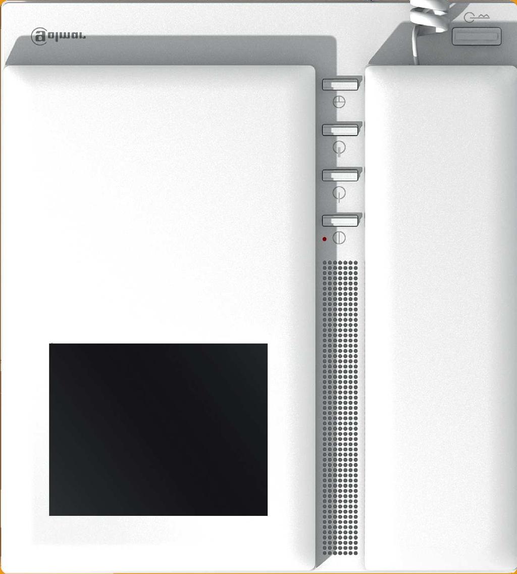
4 INTER A1 SLAVE MASTER COE ATENCIÓN Alta tensión. No abrir la tapa. Manipular sólo por personal del servicio técnico. WARNING High voltage. on't open cover. Handle only by technical service. ESCALERA STAIR PISO FLOOR PUERTA OOR SN TEKNA PLUS SE MONITOR 4 ESCRIPTION OF THE MONITOR escription of the Tekna Plus SE monitor: a g b c d e h I j k.xx REF. TEKNA PLUS SE COE l m n o escription of the identification label: f a. b. c. d. e. f. g. h. i. j. k. l. m. n. o. Handset. Colour screen. Advanced programming LE. Monitor status LE (bicoloured): - Standby: LE illuminated red. -Call: LE illuminated green (master monitor). -Communication: LE illuminated green. -"Video-spy" if busy bus: LE fast blinking red. (With monitor V03 or later). -Night mode: LE blinking red. -octor mode: LE blinking green Function / programming push buttons. Telephone cord. Attachment holes. Identification label. Connecting points. IP switches. RJ-45 connector (installation with UTP cable). CN4 connector. Cord connector. Contrast control. Brightness control..xx INTER A1 SLAVE MASTER COE ATENCIÓN Alta tensión. No abrir la tapa. Manipular sólo por personal del servicio técnico. WARNING High voltage. on't open cover. Handle only by technical service. REF. TEKNA PLUS SE ESCALERA STAIR COE PISO FLOOR PUERTA OOR SN To facilitate repair, replacement or the addition of monitors to the existing installation, fill in the label with the relevant information. MASTER: main monitor. SLAVE: secondary monitor. INTER: secondary monitor with intercom function. A1: monitor connected to an auxiliary device. COE: call button code. STAIRWAY: code of the channel (building).
5 TEKNA PLUS SE MONITOR 5 ESCRIPTION OF THE MONITOR Function push buttons: ( ) * ( ) * One short press for 1 second, with the monitor in standby and the handset on or off the hook, activates night mode on the monitor, confirmed by the status LE blinking red. uring a call, the monitor does not emit a ringtone unless it is an apartment front door call. One long press for 3 seconds, with the monitor in standby and the handset on or off the hook, turns the monitor on or off.after any resetting of the monitor and for the following 45 seconds, no operation with it can be performed. One long press for 3 seconds during a call cancels the call on the monitor. If there are more monitors in the apartment, they will continue with the ringtones of the door panel. uring communication with the door panel, the communication in progress will end. With the handset lifted, the intercom (in the same apartment) is activated. One long press until a confirmation tone can be heard will call all of the monitors in the apartment. To call individual devices, press the button once to call the master monitor, twice to call slave 1 ", 3 times to call slave 2 ", 4 times to call slave 3" and 5 times to call slave 4 ". This selective intercom call mode is only available with the Tekna Plus SE monitor. This only functions if no call or communication is in progress. Regardless of the position of the handset, the auxiliary device is activated. With the handset hung up, the image from the door panel configured as master can be viewed (if busy bus, the monitor status LE will indicate with fast blinking red. With monitor V03 or later). With the handset lifted, audio and video communication can be established with the door panel if it has its auto switch-on function activated. This only functions if no communication is in progress. With the handset hung up, a panic call to the guard units configured to receive such calls is made. With the handset lifted, a normal call can be made to the main guard unit. uring call reception and communication processes, the door release can be activated. (*) In advanced programming mode, the default functions of function push buttons and can be changed with one of the following functions at the same time and per button: intercom, auxiliary device activation, second camera activation or call to s lave porter's exchange (see page 12). escription of the SW2 IP switch: The SW2 IP switch is located on the left-hand side of the back of the monitor. It enables the monitor to be configured as master / slave and an address to be assigned. Important: This type of programming cannot be performed on a general entrance door panel. IP1 and IP2: To set the monitor as master / slave. IP1 and IP2 to OFF, master, IP1 to ON and IP2 to OFF, slave 1, IP1 to OFF and IP2 to ON, slave 2, IP1 and IP2 to ON slave 3. IP3 to IP10: To set the monitor address (addresses 1 to 255). The switches set to OFF have a zero value. The values of the switches set to ON are shown in the table below. The monitor code is the sum of the values of the switches set to ON. Switch number: Value when ON: *Factory setting Example: =87
 in twisted-pair installations.")


6 6 ESCRIPTION OF THE MONITOR escription of the RJ-45 connector (installation with UTP cable): The monitor features an RJ-45 connector for installation with a UTP cable. It is located on the left-hand side of the back of the monitor. It enables connection of the system's main communication wires (, -, A,, Vp y Mp) in twisted-pair installations. RJ-45 equivalence table RJ-45 connector (cable type: T568B) Pin Ethernet cable White Orange Orange White Green Blue White Blue Golmar connection GN (Audio) Audio GN (at a) 18V 18V PA IR 3 PA IR 2 PA IR 1 PA IR Green ata 7 8 White Brown Brown Vp Mp Male connector Female connector MONITOR AJUSTMENTS Handling of the end of line jumper: The end of line jumper is located on the CN4 connector at the back of the monitor. In the case of twisted pair installations, the end of line jumper is located in the EL562 module (see next section). o not remove the jumper if the video cable ends in the monitor. Remove the jumper if the video cable continues after the monitor. EL562 module for video door entry system installations with twisted pair cable: Locate the CN4 connector at the back of the monitor. To insert the EL562 module, remove the jumper that is in the connector. NOTE: In this type of installation, set the SW1-3 IP switches on the sound module of the door panel to ON, see instruction manual T632/Plus ML (page 13), or the SW1-3 IP switches on the EL500SE microprocessor to ON, see manual T5000 ML (page 7). The door panel of the SV801SE GRF kit does not require modification. Use the specific wiring diagram.
 Presionar para abrir. Press to open. Colocar la parte superior de la regleta a 1,60m. del suelo. Place the top part of the monitor connector at 1,60m. from the floor.")

7 7 ESCRIPTION OF THE WALL MOUNT CONNECTION BLOCK escription of the RCTK-PLUS wall mount connection block: a c b d 18 CABLE 17 b Max. pelado del cable. Max. peeled cable. 50mm. ( * ) 50mm. ( * ) Presionar para abrir. Press to open. Colocar la parte superior de la regleta a 1,60m. del suelo. Place the top part of the monitor connector at 1,60m. from the floor. ( * ) istancia mínima entre los laterales de la regleta y cualquier objeto debe ser de 5cm COE REF RCTK-PLUS Max. 5mm Max. câble dénudé. Max. aanstrip lengte. LOTE IMP Vin Malla Shield Malla Shield Vout HZ- SA 2C A1 VP VP MP MP 90 Vin Malla Shield Malla Shield Vout A INT SA CTO OA1 OA1 VP Vin Malla Shield 13 Malla Shield 12 Vout A HZ- INT SA AP 2C A1 VP MP MP 1 CETK590 PLUS e f a a. Holes for fixing to wall (x6). b. Monitor fixing clips (x2). c. Vertical wiring entry. d. Fixing clip. e. Central wiring entry. f. Connection terminals:, : Vin : M esh: Vout : A : : HZ- : INT : SA : AP : 2C : A1 : Vp, Mp : positive, negative. video signal input through coaxial cable. coaxial cable mesh. video signal output through coaxial cable. audio communication. digital communication. door bell push button input. intercom. auxiliary call repeater output. auxiliary door opening push button input. 2nd camera activation output. auxiliary device activation output. balanced video signal (through twisted pair). The, and mesh terminals are duplicated to facilitate the cascade connection of other monitors or telephones. If the - monitor is not positioned on the wall mount connection block, the cascade connected monitors or telephones will not receive power.


8 8 INSTALLATION OF THE MONITOR Fixing the monitor's wall mount connection block to the wall: Avoid dusty or smoky environments or locations near sources of heat. To fix the monitor directly to the wall, drill four Ø6mm holes and use the plugs and screws supplied. The top of the wall mount connection block must be positioned at a height of 1.60m. The minimum distance between the sides of the wall mount connection block and the closest object must be 5cm. Fixing the monitor's wall mount connection block to the wall: Place the monitor at right angles to the wall mount connection block and align the holes on its base with the fixing clips of the connection block, as shown in the drawing. Close the monitor like a book, applying pressure to the right-hand side until the click of the connection block's fixing clips can be heard. To remove the monitor from the connection block after installation, use a flat screwdriver to release the fixing clips. Once the monitor has been released, open it like a book and remove it from the connection block, making sure that it does not fall.
9 9 PROGRAMMING THE MONITORS Programming the TEKNA PLUS SE monitor: Locate the SW2 IP switch on the EL632 Plus sound module or the EL500SE microprocessor and set to ON. In systems with more than one door panel, only perform this procedure on the main door panel of each building. Important: To perform this programming, the monitor's SW2 IP switches should be set to OFF. Switch off the monitor to be programmed. Once switched off, press the door release push button. While keeping the door release push button pressed, switch on the monitor. To show that the system is ready for programming, the door panel will emit a number of tones and an image will appear on the monitor, at which point the door release push button can be released. To establish audio communication with the door panel, lift the handset. Press the door panel push button. At this moment, the door panel will emit a number of tones and the monitor's LE will blink red. M To programme the monitor as Master, press button for 3 seconds. S To programme the monitor as Slave 1, press button once, and the status LE will blink green once. Continue successively to Slave 4, pressing button four times, with the status LE blinking green four times. SI To programme the monitor as Slave with intercom, press button and the status LE will blink green once. Continued overleaf

10 TEKNA PLUS SE MONITOR 10 PROGRAMMING THE MONITORS Continued from the previous page. SV To programme the monitor as Slave without video, press button and the status LE will blink green once. If button is pressed again, the monitor will return to being programmed as Slave with video, and the status LE will blink green twice. The door panel video will be displayed during a call depending on whether the monitor has been programmed as: Slave with video or Slave without video. Each apartment must only have one master unit; if there are parallel units, either monitors or telephones, they must be configured as slaves. Make a call to check that the monitor has been successfully programmed. Programme the other telephones in the same way. Once the programming has finished, set the programming switch to OFF. If this is not done, the door panel will emit tones to indicate that the system is still in programming mode. Quick programming of the Tekna Plus SE monitors: The SW2 IP switch is located on the left-hand side of the back of the monitor. It enables the monitor to be configured as master / slave and an address to be assigned. Important: This type of programming cannot be performed on a general entrance door panel. IP1 and IP2: To set the monitor as master / slave. IP1 and IP2 to OFF, master, IP1 to ON and IP2 to OFF, slave 1, IP1 to OFF and IP2 to ON, slave 2, IP1 and IP2 to ON slave 3. IP3 to IP10: To set the monitor address (addresses 1 to 255). The switches set to OFF have a zero value. The values of the switches set to ON are shown in the table below. The monitor code is the sum of the values of the switches set to ON. Switch number: Value when ON: Example: =87 *Factory setting
11 11 AVANCE PROGRAMMING (MONITOR FUNCTIONS) Advanced programming of the functions of the Tekna Plus SE monitor: Advanced programming enables the monitor's default settings to be changed: Switch off the monitor to be programmed. Once switched off, press button for 3 seconds to enter " Menu 1" of advanced programming, and the programming LE will illuminate. Menu 1: Then adjust the settings as required: - Adjusting the call volume: High volume (default setting). Adjusting the call volume: Press button to select the required volume. (Options: minimum, medium and maximum). Regardless of the volume set, the apartment front door call ringtone will always sound at the highest level. - Changing the ringtone melody: The monitor has different ringtones to identify the origin of the call. The melodies assigned by default to the ringtones can be selected from among others available on the monitor. Select the ringtone to be changed: Each press on button selects a ringtone which is indicated with blinks (1 to 4 blinks) of the programming LE and in the following order: door panel, guard unit, intercom call and HZ apartment front door call. When the final selection is reached, the following press returns the user to the first selection and 1 blink of the programming LE (carousel mode). Then select the melody for the ringtone (selected in the previous step) by pressing button until the required carousel mode melody is heard. - Activating / deactivating the doctor mode function: octor mode not activated (default setting). The doctor mode function enables the door release to be activated automatically 6 seconds after making a call from the door panel without having to establish communication or press door release button. The call ends after 20 seconds and the channel is freed. (Only the master monitor should be configured with doctor mode ). To activate doctor mode: Press button, and the programming LE will indicate with 2 blinks that the function is activated or with 1 blink that the function is deactivated. - Accessing " Menu 2" or exiting programming mode: To access " Menu 2", press button, and the programming LE will blink twice. To exit programming mode, press button for 3 seconds, and the programming LE will turn off (see page 14). Continued overleaf
12 12 AVANCE PROGRAMMING (MONITOR FUNCTIONS) Continued from the previous page. Menu 2: Then adjust the settings as required: - Button has no function. No function. - Changing the function of button : Intercom function (default setting). Select the function to assign to button : Each press on button selects a different function which is indicated with blinks (1 to 4 blinks) of the programming LE and in the following order: auxiliary device activation " A1 ", call to s lave porter's exchange, second camera activation " 2C" and intercom. When the final selection is reached, the following press returns the user to the first selection and 1 blink of the programming LE (carousel mode). - Changing the function of button : Auxiliary device activation function. " A1 " (default setting). Select the function to assign to button : Each press on button selects a different function which is indicated with blinks (1 to 4 blinks) of the programming LE and in the following order: auxiliary device activation " A1 ", call to s lave porter's exchange, second camera activation " 2C" and intercom. When the final selection is reached, the following press returns the user to the first selection and 1 blink of the programming LE (carousel mode). - Intercom with Tekna Plus monitors: Intercom with Tekna Plus SE monitors (default setting). If an apartment has Tekna Plus and Tekna Plus SE monitors, the Tekna Plus SE monitors should be configured with Intercom with Tekna Plus monitors mode, as Tekna Plus monitors do not allow an intercom call to a particular monitor in the apartment to be made (selective intercom call). So when an intercom call is made, all of the monitors in the apartment will receive the call. To activate the Intercom with Tekna Plus monitors mode: Press button, and the programming LE will indicate with 1 blink that the function is in Intercom with Tekna Plus monitors mode or with 2 blinks that the function is in Intercom with Tekna Plus SE monitors mode. - Accessing " Menu 3" or exiting programming mode: To access " Menu 3", press button, and the programming LE will blink 3 times. To exit programming mode, press button for 3 seconds, and the programming LE will turn off (see page 14). Continued overleaf
13 13 AVANCE PROGRAMMING (MONITOR FUNCTIONS) Continued from the previous page. Menu 3: Then adjust the settings as required: - Repeating the ringtones: One repeat (default setting). To repeat the ringtone on the monitor: Each press on button selects a repeat of the ringtones which is indicated with blinks (1 to 3 blinks) of the programming LE and in the following order: 1, 2 or 3 repeats. When the final selection is reached, the following press returns the user to the first selection and 1 blink of the programming LE (carousel mode). - Adjusting the door panel communication time : 90 seconds (default setting). To adjust the door panel communication time : Each press on button selects a communication time which is indicated with blinks (1 to 4 blinks) of the programming LE and in the following order: 60, 90, 120 and 150 seconds. When the final selection is reached, the following press returns the user to the first selection and 1 blink of the programming LE (carousel mode). Not e: This adjustment can be performed on Nexa door panels with EL632 Plus sound module. (Please consult our technical service department for information about other models of door panel). - Adjusting the door panel call time : 45 seconds (default setting). T o adjust the door panel call time : Each press on button selects a call time which is indicated with blinks (1 to 4 blinks) of the programming LE and in the following order: 30, 45, 60 and 90 seconds. When the final selection is reached, the following press returns the user to the first selection and 1 blink of the programming LE (carousel mode). Not e: This adjustment can be performed on Nexa door panels with EL632 Plus sound module. (Please consult our technical service department for information about other models of door panel). - Activating the in-call video: The video appears when a call is received (default setting). Activating the in-call video: Press button, and the programming LE will indicate with 2 blinks that the video will appear on the monitor when a call is received or with 1 blink that the video will appear at the end of the ringtone. - Accessing " Menu 4" or exiting programming mode: To access " Menu 4 ", press button, and the programming LE will blink 4 times. To exit programming mode, press button for 3 seconds, and the programming LE will turn off (see page 14). Continued overleaf
14 14 AVANCE PROGRAMMING (MONITOR FUNCTIONS) Continued from the previous page. Menu 4: Then adjust the settings as required: - " efault setting ", a ll the advanced monitor programming options: Set to "default setting": Press button, and the monitor will indicate with 2 acoustic tones that all the options of the advanced programming of the monitor (pag ) are with its default setting. (With monitor V03 and later). - Button has no function. No function. - Button has no function. No function. - Button has no function. No function. - Accessing " Menu 1" or exiting programming mode: To access " Menu 1 ", press button, and the programming LE will blink once (see page 11). To exit programming mode, press button for 3 seconds, and the programming LE will turn off. - Turning on the monitor when exiting programming: When exiting advanced programming mode, the monitor will turn off: Press button for 3 seconds to turn the monitor back on. After any resetting of the monitor and for the following 45 seconds, no operation with it can be performed.
15 15 OPTIONAL CONNECTIONS Auxiliary device activation with Tekna Plus SE monitors: Auxiliary device activation requires the use of an SAR-12/24 relay unit. If the feature is shared by all monitors, connect their A1 terminals; if, however, each monitor has its own feature, use an SAR-12/24 relay for each one and do not connect their A1 terminals. This function is activated when button is pressed on the monitor at any time and regardless of the position of the handset. The most common applications are activating the stairway lights and opening a second door. Tekna Plus SE NC NA C SAR-12/24 To the stairway light activation push button CN4 Mesh A V in V out A1 IN IN To the distributor/ door panel. F N 220 V ac/ 1.8A max. ) ( * ( ) * The neutral of the lighting power supply is arranged serially through the contacts of the SAR-12/24 relay and the maximum consumption of the element to be connected does not exceed 1.8A. To activate a second door release, a TF-104 transformer is required. Tekna Plus SE NC NA C SAR-12/24 TF-104 CN4 Mesh A V in V out A1 IN IN PRI SEC ~ ~ ~ ~ To the distributor/ door panel. Mains * Vac lock release * Important: Place the varistor supplied with the sound module directly onto the terminals of the lock release. Exterior push button input for activating the door panel door release: This enables the door panel door release to be activated during a call or communication with the door panel. With the monitor in standby, it makes a panic call to the porter's exchanges configured to receive this type of call. Tekna Plus SE AP AP Continued overleaf
16 16 OPTIONAL CONNECTIONS Continued from the previous page. Intercom between two points in the same apartment: The Tekna Plus SE monitor features as standard an intercom function between two points in the same apartment. To enable this feature, the following is necessary: - One of the monitors needs to be configured as master and the other as slave with intercom, as described on page 9. In the case of intercom between a monitor and a telephone, it is recommended to configure the monitor as the master. - The INT terminal of the intercom devices need to be connected (see diagram attached). To use the intercom function to call all of the monitors in the apartment, lift the handset and press the button until a confirmation tone can be heard. To call individual devices, press the button once to call the " master" monitor, twice to call " slave 1 ", 3 times to call " slave 2 ", 4 times to call " slave 3" and 5 times to call " slave 4 ". This selective intercom call mode is only available with the Tekna Plus SE monitor. This only functions if no call or communication is in progress. A number of audible tones emitted by the handset will confirm that the call is being made or that the unit being called is in communication with the door panel. To establish communication, lift the handset of the unit being called. If a call is received from the door panel during an intercom process, the handset of the master unit will emit a number of audible tones and an image will appear. To establish communication with the door panel, press button on the unit configured as master or press the door release push button to simply open the door. The ringtones vary depending on where the call is made from to enable the user to identify its origin. Note: If the apartment also has Tekna Plus monitors, the Tekna Plus SE monitors must be configured as " Intercom with Tekna Plus monitors " (see page 12). This configuration mode does not allow selective intercom calls to different monitors in the apartment; when the intercom button is pressed, all of the monitors in the apartment will receive the call. Tekna Plus SE Tekna Plus SE CN4 Mesh A INT V in V out CN4 Mesh A INT V in V out Connection of the Tekna Plus monitor to a television or video: If the television or video has a SCART socket, an image of the caller can be displayed on the television screen via the auxiliary channel. Remove the 75-ohm end-of-line jumper resistor located on the CN4 connector on the back of the monitor. Connect the coaxial cable to terminals 17 (mesh) and 20 (live) of the SCART connector. Tekna Plus SE CN4 Mesh A V in V out Continued overleaf
17 17 OPTIONAL CONNECTIONS Continued from the previous page. Button for receiving calls from the apartment front door: The Tekna Plus SE monitor features as standard the ability to receive calls from the apartment front door. This feature precludes the need to use the bell by positioning a switch between terminals HZ and of the monitor The ringtones vary depending on where the call is made from to enable the user to identify its origin. If a call is made from the apartment front door during a conversation with the door panel, the handset will emit a number of tones to indicate so. Not e: Regardless of the volume set for the monitor's ringtones (see page 11) and the night mode function, the apartment front door call ringtone will always sound at the highest level. Tekna Plus SE - HZ- CLEANING THE MONITOR - o not use solvents, detergents or cleaning products that contain acids, vinegar or abrasive components. - Use a soft damp cloth (not wet) that sheds no fibres. - Always wipe the monitor in the same direction, from top to bottom. - After cleaning the monitor, remove any moisture with a soft dry cloth that sheds no fibres.
18 18 WIRING IAGRAMS Video door entry system with coaxial cable: Remove the JP1 jumper from all of the distributors except the last. 4L-PLUS CN4 S JP1 CN4 V in Mesh V out A 1 E 2 Mesh A V in V out 4L-PLUS CN4 S JP1 CN4 V in Mesh V out A 1 E 2 Mesh A V in V out M =Master. Place this power supply as close as possible to the first distributor CN M SW2 FA-Plus/C or FA-Plus SW1 ~ PRI ~ SEC - - CV2 CV1 - - CN1 Aout Ain Vin- Vin Mesh Vout Vout- Mains C lock release Important: For further information about the door panel, sections, distances, other wiring diagrams, etc., see the T632 PLUS ML User Manual.
19 19 WIRING IAGRAMS Video door entry system without coaxial cable: EL562 JP1 EL562 JP1 A V p M p M d1 * Remove the JP1 jumper from all of the distributors except the last. A V po M po 6L-Plus/2H M d6 A V p M p V d1 V d6 A CT A JP1 V pi M pi A CT EL562 JP1 EL562 JP1 A V p M p A V p M p M d1 A V po M po 6L-Plus/2H M d6 V d1 V d6 A CT A JP1 V pi M pi A CT M =Master. *Place this power supply as close as possible to the first distributor CN M SW2 FA-Plus/C or FA-Plus SW1 ~ PRI ~ SEC - - CV2 CV1 - - CN1 Aout Ain Vin- Vin Mesh Vout Vout- Mains C lock release Important: For further information about the door panel, sections, distances, other wiring diagrams, etc., see the T632 PLUS ML User Manual.

20 Sistemas de comunicación S.A. GOLMAR S.A. C/ Silici, Cornellá de Llobregat SPAIN Golmar se reserva el derecho a cualquier modificación sin previo aviso. Golmar se réserve le droit de toute modification sans préavis. Golmar reserves the right to make any modifications without prior notice.
TECHNOLOGY USER MANUAL. Audio and Video Door Entry System Nexa Modular Gb2 2-Wire
 TEHNOOGY USER MANUA Audio and Video Door Entry System Nexa Modular Gb2 2-Wire AWD267 Rev. 08/2018 2 TENTS Introduction......2 ontents.....2. Set-up warnings......2. Safety precautions...... 3 haracteristics...3
NEXA MODULAR GB2 AUDIO AND VIDEO DOOR ENTRY SYSTEM - BUILDING
 2 INTRODUTI First and foremost we would like to thank you for purchasing this product. Our commitment to achieving the satisfaction of customers like you is manifested through our ISO-9001 certification
Description Diagram Page
 notiziario tecnico 2004 SISTEMA VIDEO 4+n installation wiring diagrams VIDEO SYSTEM 4+n INDEX: Description Diagram Page Section of wires 2/UK Suggestions for the correct installation 3/UK Terminal functions
LED Backlight for Technics amplifiers
 LED Backlight for Technics amplifiers Technics SE-A900S Technics SE-A900SM2 Technics SE-A909S Technics SE-A1000 Technics SE-A1000M2 Technics SE-A1010 Rev. 1.2 B Description The LED module is designed to
Enterview 2 / Enterview 2V 4 WIRE VIDEO DOORPHONE SYSTEM
 Enterview / Enterview V WIRE VIDEO DOORPHONE SYSTEM INSTALLATION AND OPERATION. Introduction This Video doorphone System is an easy-to-use system offering many benefits and conveniences, such as relieving
VIDEO DOOR PHONE CAV-51M
 VIDEO DOOR PHONE CAV-51M 513-11, Sangdaewon-dong, Jungwon-gu, Seongnam-si, Gyeonggi-do, Korea Int l Business Dept. : Tel.; +82-31-7393-540~550 Fax.; +82-31-745-2133 Web site : www.commax.com Printed In
Video Door Entry System Kits 2 Wires Installation
 Video Door Entry System Kits 2 Wires Installation Safety & Operating Instructions Réf. NVM-902/NVC-9102B1+NPS-17 2014-10-20 These instructions are for your safety. Please read through them thoroughly before
User Manual Wide Color Video Phone
 User Manual Wide Color Video Phone CAV-43T2 Thank you for purchasing COMMAX products. Please carefully read this User s Guide (in particular, precautions for safety) before using a product and follow instructions
User Manual Color Video Door Phone
 User Manual Color Video Door Phone CMV-43A Thank you for purchasing COMMAX products. Please carefully read this User s Guide (in particular, precautions for safety) before using a product and follow instructions
User Manual Color video door phone
 User Manual Color video door phone CDV-70AR3 Thank you for purchasing COMMAX products. Please carefully read this User s Guide (in particular, precautions for safety) before using a product and follow
User Manual Color video door phone
 User Manual Color video door phone CDV-43Q Thank Thank you you for for purchasing purchasing COMMAX COMMAX products. products. Please Please carefully carefully read read this this User s User s Guide
User Manual. Color video door phone CDV-70P PM0770P Printed In Korea /
 User Manual Color video door phone CDV-70P 513-11, Sangdaewon-dong, Jungwon-gu, Seongnam-si, Gyeonggi-do, Korea 513-11, Sangdaewon-dong, Jungwon-gu, Seongnam-si, Gyeonggi-do, Korea Business Dept. : +82-31-7393-540~550
VIDEO DOOR PHONE. Model No. APV-4PM
 VIDEO DOOR PHONE Model No. APV-4PM Thank you for purchasing our COMMAX product. Please carefully read this User s Guide (in particular, precautions for safety) before using the product and follow the instructions
Telemetry Receiver Installation Guide
 BBV Telemetry Receiver Installation Guide Models covered Rx200 Building Block Video Ltd., Unit 1, Avocet Way, Diplocks Industrial Estate, Hailsham, East Sussex, UK. Tel: +44 (0)1323 842727 Fax: +44 (0)1323
PLL1920M LED LCD Monitor
 PLL1920M LED LCD Monitor USER'S GUIDE www.planar.com Content Operation Instructions...1 Safety Precautions...2 First Setup...3 Front View of the Product...4 Rear View of the Product...5 Installation...6
Art M Digital codelock module
 CODELOCK UNIT MODULES Art. 4900-4900M This module has on the front a 12 stainless steel button keypad (keys from 0 to 9 plus ENTER and CLEAR keys), 2 LEDS for operation signalling, the keypad illumination
User Manual. Color video door phone CDV-40Q
 User Manual Color video door phone CDV-40Q Thank Thank you you for for purchasing purchasing COMMAX COMMAX products. products. Please Please carefully carefully read read this this User s User sguide Guide(in
SMART SYSTEM DUOX SYSTEM GUIDE
 SMART SYSTEM DUOX SYSTEM GUIDE This document shows the basic concepts for a quick start-up. For more information download the manuals at www.fermax.com Technical publication of an informative nature published
FD Trinitron Colour Television
 R 4-205-569-32(1) FD Trinitron Television Instruction Manual GB KV-14LM1U 2000 by Sony Corporation NOTICE FOR CUSTOMERS IN THE UNITED KINGDOM A moulded plug complying with BS1363 is fitted to this equipment
PLL2210MW LED Monitor
 PLL2210MW LED Monitor USER'S GUIDE www.planar.com Content Operation Instructions...1 Safety Precautions...2 First Setup...3 Front View of the Product...4 Rear View of the Product...5 Quick Installation...6
PLL2710W LED LCD Monitor
 PLL2710W LED LCD Monitor USER'S GUIDE www.planar.com Content Operation Instructions...1 Safety Precautions...2 Package Overview...3 First Setup...4 Front View of the Product...5 Rear View of the Product...6
UK. Multi Channel Programmable Filter-Equalizer. User Manual FEATURES. - Designed for both digital and analogue channels,
 Multi Channel Programmable Filter-Equalizer User Manual 6506 6506UK FEATURES - Designed for both digital and analogue channels, - 2 UHF input / 1 output, - 8 programmable clusters, - UHF channels 21 to
Documentation on all Paxton products can be found on our web site -
 11/05/2012 Ins-30202-US Net2 Entry - Monitor Paxton Technical Support 1.800.672.7298 supportus@paxton-access.com Technical help is available: Monday - Friday from 02:00 AM - 8:00 PM (EST) Documentation
Unlocking of building entrance door shall be possible by pressing the monitor's door-opener button.
 DIGITAL COLOR VIDEO INTERCOM SYSTEM The contractor shall supply, install, test and commission a modern Electronic Digital Color Video Entry Phone System of an approved manufacturer and design to facilitate
VNS2210 Amplifier & Controller Installation Guide
 VNS2210 Amplifier & Controller Installation Guide VNS2210 Amplifier & Controller Installation 1. Determine the installation location for the VNS2210 device. Consider the following when determining the
VNS2200 Amplifier & Controller Installation Guide
 VNS2200 Amplifier & Controller Installation Guide VNS2200 Amplifier & Controller Installation 1. Determine the installation location for the VNS2200 device. Consider the following when determining the
MAX T200 HD QUICK INSTALLATION GUIDE
 MAX T200 HD QUICK INSTALLATION GUIDE MAX T200 HD QUICK INSTALLATION GUIDE CONTENT receiver BATTERIES x 2 REMOTE CONTROL Quick installation guide Quick Installation Guide The lightning flash with arrowhead
PNP300 / PNP300UN / PNP350
 DOCUMENT NUMBER 400-0114-003 / UN / PNP350 Pop N Plug Slim INTERCONNECT BOX USER'S GUIDE TABLE OF CONTENTS Page PRECAUTIONS / SAFETY WARNINGS...2 GENERAL...2 INSTALLATION...2 CLEANING...2 ABOUT YOUR /300UN/350...3
Q-TV2. User Manual. for Screens
 Q-TV2 User Manual for 30-42 Screens Contents Introduction 02 Safety Guidelines 03 Getting started 03 Potential Uses 04 Carton Contents 05 Q-TV2 Controls 05 Remote Fixings 06 Fixing Rails 07 Fitting Q-TV2
PXL2470MW LED LCD Monitor
 PXL2470MW LED LCD Monitor USER'S GUIDE www.planar.com Content Operation Instructions...1 Unpacking Instructions...2 Safety Precautions...2 Package Overview...3 First Setup...4 Front View of the Product...5
PXL2760MW LED LCD Monitor
 PXL2760MW LED LCD Monitor USER'S GUIDE www.planar.com Content Operation Instructions...1 Safety Precautions...2 Package Overview...3 First Setup...4 Front View of the Product...5 Rear View of the Product...6
PL2410W LCD Monitor USER'S GUIDE.
 PL2410W LCD Monitor USER'S GUIDE www.planar.com Content Operation Instructions...1 Safety Precautions...2 First Setup...3 Front View of the Product...4 Rear View of the Product...5 Quick Installation...6
User Guide. Centrex Recording Interface
 User Guide Centrex Recording Interface Table of Contents Introduction... 2 The Meridian Business Set... 3 Key Numbering Plan (18 button add-on)... 4 Key Numbering Plan (36 button add-on)... 5 Key Numbering
CS x1 RS-232 Computer Controlled Video Switcher. Instruction Manual
 CS-1600 16x1 RS-232 Computer Controlled Video Switcher Instruction Manual Thank you for purchasing one of our products. Please read this manual before using this product. When using this product, always
Installer Manual Video door entry unit with 3.5" monitor for Due Fili (Two-Wire) call system Elvox Vimar Group.
 call system Elvox Vimar Group.") Installer Manual 19558 Video door entry unit with 3.5" monitor for Due Fili (Two-Wire) call system Elvox Vimar Group. Table of Contents Technical characteristics 3 Type of system 3 Advantages of the Due
Installer Manual 19558 Video door entry unit with 3.5" monitor for Due Fili (Two-Wire) call system Elvox Vimar Group. Table of Contents Technical characteristics 3 Type of system 3 Advantages of the Due
Product information. Front-door station series with video for surface-mount
 Product information Front-door station series with video for surface-mount series VPES series VPDS 2 05/2006 Table of contents Scope of delivery...3 Safety notices...3 General notes on the cabling in TCS
User Manual. Fineview Video Phone CDV-43MH/CDV-43MH(M)
") User Manual Fineview Video Phone CDV-43MH/CDV-43MH(M) Thank Thank you you for for purchasing purchasing COMMAX COMMAXproducts. products. Please Please carefully carefully read read this this User s User
User Manual Fineview Video Phone CDV-43MH/CDV-43MH(M) Thank Thank you you for for purchasing purchasing COMMAX COMMAXproducts. products. Please Please carefully carefully read read this this User s User
ACT 10 Digital Keypad Operating & Installation Instructions This manual is found at
 ACT 10 Digital Keypad Operating & Installation Instructions 18-00001 This manual is found at www.eaglesecuritysolutions.co.uk Installation Notes Always remember to factory default the controller before
FOREST SHUTTLE S / L / M RECEIVER
 2 FOREST SHUTTLE S / L / M RECEIVER QUICK INSTALLATION OF ASSEMBLED TRACKS : Programming Shuttle S / L / M Receiver to a channel One pre-assembled motorized curtain track systems is standard programmed
USER MANUAL. 22" Class Slim HD Widescreen Monitor L215DS
 USER MANUAL 22" Class Slim HD Widescreen Monitor L215DS TABLE OF CONTENTS 1 Getting Started Package Includes Installation 2 Control Panel / Back Panel Control Panel Back Panel 3 On Screen Display 4 Technical
STX Stairs lighting controller.
 Stairs lighting controller STX-1795 The STX-1795 controller serves for a dynamic control of the lighting of stairs. The lighting is switched on for consecutive steps, upwards or downwards, depending on
Multi channel programmable Filter-Amplifier
 Operating instructions VS 21 Multi channel programmable Filter-Amplifier Operation LED Handset OK 41A For digital and analogue channels 6 terrestrial inputs: B I-II / B III / VHF-UHF and 3 UHF inputs over
Multi Channel Programmable Filter-Amplifier. User Manual I-II III V-U SAT. Stop Channel SAT Slope Start Channel SAT ON / OFF.
 R Ref. : 6602 Multi Channel Programmable FilterAmplifier User Manual Digital Terrestrial B III B III VHFUHF UHF1 24V 0 22 khz UHF2 24V 18V 24V 24V 13V 0V UHF3 III III VU GND R MULTI CHANNEL PROGRAMMABLE
OPERATIONAL MANUAL EMZS CH Speaker Zone Selector. Version 1.6
 OPERATIONAL MANUAL EMZS-8012 12CH Speaker Zone Selector Version 1.6 1 Product Overview The EMZS-8012 is a 1U rack-mounting unit, provide 12 channel direct zone switching for single source public address
Telemetry Receiver Installation Guide
 BBV Telemetry Receiver Installation Guide Models covered Rx400P Building Block Video Ltd., Unit 1, Avocet Way, Diplocks Industrial Estate, Hailsham, East Sussex, UK. Tel: +44 (0)1323 842727 Fax: +44 (0)1323
HAND-FREE COLOR VIDEO DOORPHONE. Installation and Operation Manual
 HAND-FREE COLOR VIDEO DOORPHONE Installation and Operation Manual TABLE OF CONTENTS 1. Brief introduction 2. Functions 3. Descriptions as illustrated 4. Preparations before installation 5. Installation
COLOUR TFT LCD MONITOR USER S MANUAL Model: C172
 COLOUR TFT LCD MONITOR USER S MANUAL Model: C172 The display comes with a three year on site warranty. To activate your warranty please register your display at http://www.edge10.com by clicking on the
PNP300 & PNP350 POP N PLUG SLIM INTERCONNECT BOX USER S GUIDE
 The is shown above. MANUAL PART NUMBER: 400-0114-004 & PNP350 POP N PLUG SLIM INTERCONNECT BOX USER S GUIDE TABLE OF CONTENTS Page PRECAUTIONS / SAFETY WARNINGS... 2 GENERAL...2 HANDLING...2 CLEANING...2
Dragonfly Quad. User Manual V1.4. Order code: EQLED101
 Dragonfly Quad User Manual V1.4 Order code: EQLED101 Safety advice WARNING FOR YOUR OWN SAFETY, PLEASE READ THIS USER MANUAL CAREFULLY BEFORE YOUR INITIAL START-UP! Before your initial start-up, please
Quick Operation Guide of LTN7700/7600 Series NVR
 Quick Operation Guide of LTN7700/7600 Series NVR UD.6L0202B0042A02 Thank you for purchasing our product. If there is any question or request, please do not hesitate to contact dealer. This manual is applicable
Stage Wash 7x 10W LED Moving Head (RGBW)
") Stage Wash 7x 10W LED Moving Head (RGBW) P/N 612870 User's Manual CONTENTS SAFETY WARNINGS AND GUIDELINES... 3 INTRODUCTION... 4 FEATURES... 5 CUSTOMER SERVICE... 5 PACKAGE CONTENTS... 6 PRODUCT OVERVIEW...
Stage Wash 7x 10W LED Moving Head (RGBW) P/N 612870 User's Manual CONTENTS SAFETY WARNINGS AND GUIDELINES... 3 INTRODUCTION... 4 FEATURES... 5 CUSTOMER SERVICE... 5 PACKAGE CONTENTS... 6 PRODUCT OVERVIEW...
Winmate Communication INC.
 20.1 Military Grade Display Model: R20L100-RKA2ML User s Manual Winmate Communication INC. May, 2011 1 IMPORTANT SAFETY INSTRUCTIONS Please read these instructions carefully before using the product and
19 / 20.1 / 22 WIDE SCREEN TFT-LCD MONITOR
 19 / 20.1 / 22 WIDE SCREEN TFT-LCD MONITOR V193/ V220 Series V202 Series USER MANUAL www.viewera.com Rev. 2.0 Table of Contents EMC Compliance......1 Important Precautions...2 1. Package contents....3
22" Touchscreen LED Monitor USER'S GUIDE
 22" Touchscreen LED Monitor USER'S GUIDE Content Operation Instructions...1 Unpacking Instructions...2 Safety Precautions...2 Front View of the Product...3 Rear View of the Product...4 Quick Installation...5
TR6102HD HDTV/DVD/COMPONENT VIDEO TO RGBHV TRANSCODER USER S GUIDE
 MANUAL PART NUMBER: 400-0031-003 PRODUCT REVISION: 1 HDTV/DVD/COMPONENT VIDEO TO RGBHV TRANSCODER USER S GUIDE INTRODUCTION Thank you for your purchase of the Transcoder. We are certain that you will find
Model#: IN-MDRI3MF. Hardware User Manual. 3MP Indoor Mini Dome with Basic WDR, Fixed lens. (PoE) Ver. 2013/02/04
 Ver. 2013/02/04") Model#: IN-MDRI3MF 3MP Indoor Mini Dome with Basic WDR, Fixed lens Hardware User Manual (PoE) Ver. 2013/02/04 Table of Contents 0. Precautions 3 1. Introduction 4 Package Contents... 4 Features and Benefits...
Model#: IN-MDRI3MF 3MP Indoor Mini Dome with Basic WDR, Fixed lens Hardware User Manual (PoE) Ver. 2013/02/04 Table of Contents 0. Precautions 3 1. Introduction 4 Package Contents... 4 Features and Benefits...
Kramer Electronics, Ltd. USER MANUAL. Model: VS x 1 Sequential Video Audio Switcher
 Kramer Electronics, Ltd. USER MANUAL Model: VS-120 20 x 1 Sequential Video Audio Switcher Contents Contents 1 Introduction 1 2 Getting Started 1 2.1 Quick Start 2 3 Overview 3 4 Installing the VS-120 in
2013, 2014 Hewlett-Packard Development Company, L.P.
 User Guide 2013, 2014 Hewlett-Packard Development Company, L.P. The only warranties for HP products and services are set forth in the express warranty statements accompanying such products and services.
INSTALLATION & USER GUIDE
 INSTALLATION & USER GUIDE Digidim 458 8-Channel Dimmer STEP 1 Assemble Dimmer Unit STEP 2 Mount Dimmer Chassis STEP 3 Electrical Installation STEP 4 Attach Module and Make Connections STEP 5 Replace Cover
Multi Channel Programmable Filter-Equalizer. Use Manual. Digital. Terrestrial. Ref. : 6505
 R Ref. : 60 Multi Channel Programmable Filter-Equalizer Use Manual 1 2 3 4 6 7 8 9 GND Terrestrial MULTI CHANNEL PROGRAMMABLE FILTER-EQUALIZER Terrestrial Ref. : 60 32 R UHF +V /00 ma FEATURES - Designed
Stratos Duo RGB. User Manual. Order code: EQLED371
 Stratos Duo RGB User Manual Order code: EQLED1 Safety advice WARNING FOR YOUR OWN SAFETY, PLEASE READ THIS USER MANUAL CAREFULLY BEFORE YOUR INITIAL START-UP! Before your initial start-up, please make
Operating Instructions
 Operating Instructions LCDRV700 Digital LCD Color Monitor Please read this manual thoroughly before operating the unit, and keep it for future reference. V1.0 Contents 1. Precautions 2. Features 1 3 3.
ARS x4 MATRIX SWITCHER Instruction Manual
 ARS-8400 8x4 MATRIX SWITCHER Instruction Manual Thank you for purchasing one of our products. Please read this manual before using this product. When using this product, always follow the instructions
SR - 516D DESK TOP DMX REMOTE STATION. Version: Date: 05/16/2013
 SR - 516D DESK TOP DMX REMOTE STATION Version: 1.10 Date: 05/16/2013 Page 2 of 10 TABLE OF CONTENTS DESCRIPTION 3 POWER REQUIREMENTS 3 INSTALLATION 3 CONNECTIONS 3 POWER CONNECTIONS 3 DMX CONNECTIONS 3
17 19 PROFESSIONAL LCD COLOUR MONITOR ART
 17 19 PROFESSIONAL LCD COLOUR MONITOR ART. 41657-41659 Via Don Arrigoni, 5 24020 Rovetta S. Lorenzo (Bergamo) http://www.comelit.eu e-mail:export.department@comelit.it WARNING: TO REDUCE THE RISK OF FIRE
Art. VR4KCLM-1 - VRCLM Digital codelock
 Fig. 1 VR4KCLM-1 Fig. 2 VRCLM CODELOCK UNIT MODULES The module features 12 stainless steel buttons (Keys 0-9, and CLEAR), 2 LED s for progress information during use and programming and a brushed finish
Color TFT LCD Monitor The Art of Surveillance
 Color TFT LCD Monitor The Art of Surveillance User Manual Table of contents Safety Information---------------------------------------------------- 1-3 Accessories----------------------------------------------------------------3
Model#: IN-DI2MIRF 2MP Indoor Dome with True Day/Night, IR, Basic WDR, Fixed lens
 Model#: IN-DI2MIRF 2MP Indoor Dome with True Day/Night, IR, Basic WDR, Fixed lens Hardware User Manual (PoE) Ver.2013/01/17 Table of Contents 0. Precautions 3 1. Introduction 4 Package Contents...4 Features
INSTALLATION GUIDE 2.4 Inch TFT Terminal Time Attendance & Access Control
 STALLATION GUIDE.4 Inch TFT Terminal Time Attendance & Access Control Optional accessories Safety Precautions The following precautions are to keep user s safe and prevent any damage. Please read carefully
Installation and operation manual. Art. 69AM/T Switching module for ELVOX DUE FILI (2-wire systems)
") Installation and operation manual Art. 69A/T Switching module for ELVOX DUE FILI (2-wire systems) CONTTS PAGE - WARNINGS FOR THE INSTALLER 2 1. GERAL INFORATION 3 2. ELECTRICAL INSTALLATION 4 3. HARDWARE
Installation and operation manual Art. 69A/T Switching module for ELVOX DUE FILI (2-wire systems) CONTTS PAGE - WARNINGS FOR THE INSTALLER 2 1. GERAL INFORATION 3 2. ELECTRICAL INSTALLATION 4 3. HARDWARE
ACCESSORIES MANUAL PART NUMBER: TNP500. Universal Tilt N Plug Interconnect Box USER'S GUIDE
 MANUAL PART NUMBER: 400-0091-003 TNP500 Universal Tilt N Plug Interconnect Box USER'S GUIDE INTRODUCTION Your purchase of the TNP100 Tilt N Plug Interconnect Box is greatly appreciated. We are sure you
Indoor/Outdoor Security System with Quad Monitor User s Manual
 Indoor/Outdoor Security System with Quad Monitor User s Manual 4919539 Important! Please read this booklet carefully before installing or using these units. WARNING - These units should ONLY be opened
Azatrax Model Railroad Track Signal Control - Single Track
 Installation Guide Azatrax Model Railroad Track Signal Control - Single Track TS2 What it is: The TS2 operates one or two trackside block signals (one in each direction) on one track to simulate the block
DDW36C Advanced Wireless Gateway - Safety and Installation Product Insert. Federal Communications Commission (FCC) Interference Statement
 Interference Statement") DDW36C Advanced Wireless Gateway - Safety and Installation Product Insert Federal Communications Commission (FCC) Interference Statement This equipment has been tested and found to comply with the limits
DDW36C Advanced Wireless Gateway - Safety and Installation Product Insert Federal Communications Commission (FCC) Interference Statement This equipment has been tested and found to comply with the limits
EN TECHNICAL MANUAL. Audio/video module for 2-wire system Art / 1621VC. Passion.Technology.Design.
 EN TEHNIA MANUA Audio/video module for 2wire system Art. / 1621 Passion.Technology.Design. Table of contents Warning Description... 2 Art. ompatibility table...2 Art. 1621 ompatibility table...2 ables
2002 Martin Professional A/S, Denmark.
 Freekie user manual 2002 Martin Professional A/S, Denmark. All rights reserved. No part of this manual may be reproduced, in any form or by any means, without permission in writing from Martin Professional
CM-S23349SV. Vari-Focal IR Bullet Camera
 Vari-Focal IR Bullet Camera User s Guide CM-S23349SV SAFETY PRECAUTIONS WARNING 1. Be sure to use only the standard adapter that is specified in the specification sheet. Using any other adapter could cause
Outdoor IR Audio Camera
 Outdoor IR Audio Camera User s Guide CM-S22326BW-AD SAFETY PRECAUTIONS WARNING 1. Be sure to use only the standard adapter that is specified in the specification sheet. Using any other adapter could cause
ACCESSORIES MANUAL PART NUMBER: PRODUCT REVISION: 1 TNP100. Tilt N Plug Interconnect Box USER'S GUIDE
 MANUAL PART NUMBER: 400-0091-001 PRODUCT REVISION: 1 TNP100 Tilt N Plug Interconnect Box USER'S GUIDE INTRODUCTION Your purchase of the TNP100 Tilt N Plug Interconnect Box is greatly appreciated. We are
Page 1 of 6 FXLD618FRP2I4 LED FIXTURE Version 0.2 OWNERS MANUAL 10/04/17
 Page 1 of 6 FEATURES AND SPECIFICATIONS LEDS: 18, 6W each (Warm White, Cool White, 2in1) Beam angle: 25º or 45 Control system: DMX512 + Stand Alone Modes DMX channels: 1/2/3/4/5 DMX connectors: 3 pin XLR
Digital Economy Seven Programmer
 Digital Economy Seven Programmer Model: TRTD7N White Installation & Operating Instructions 1. General Information These instructions should be read carefully and retained for further reference and maintenance.
E R A I GATE OPENERS DEPARTMENT
 S E R A I GATE OPENERS DEPARTMENT INSTALLATI OF THE CTROL PANEL CR/41 WHERE PLACING THE CTROL PANEL Place the device near the gate, in order to have the minimum lenght of the cables for connection with
Mini LED Pin Spot Light Model: PLS00571
 Mini LED Pin Spot Light Model: PLS00571 1 Please read these instructions carefully before use and retain for future reference. IMPORTANT SAFETY INFORMATION When using electrical appliances basic safety
The Parts of The System
 2 The Parts of The System THE RECEIVER FRONT PANEL UP DOWN POWER SMART CARD DOOR Behind this door is a slot for a future smart card. No smart card is included with this receiver. UP AND DOWN ARROW BUTTONS
Intelligent Security and Fire Ltd
 User Manual Product ranges covered by this manual Vi-P14 Vi-P14A Document Reference Date Firmware Vi-Q4C1 Viq601a.doc 26/11/2009 From Viq001a21 Videoswitch Telephone 01252-851510 Ocean House, Redfields
WDK-2500-STROBE. User Guide
 WDK-2500-STROBE User Guide Warning: This device complies with Part 15 of the FCC rules, operation of this device is subject to the following conditions: 1. This device may not cause harmful interference.
ACCESSORIES MANUAL PART NUMBER: PRODUCT REVISION: 1 PNP202. Interconnect Box USER'S GUIDE
 MANUAL PART NUMBER: 400-0109-001 PRODUCT REVISION: 1 PNP202 Interconnect Box USER'S GUIDE INTRODUCTION Your purchase of the PNP202 Interconnect Box is greatly appreciated. We are sure you will find it
LTC 113x & LTC123x FlexiDome Series Fixed Dome Cameras
 LTC 113x & LTC123x FlexiDome Series Fixed Dome Cameras Eng Installation Instructions F D E NL I IMPORTANT SAFEGUARDS 1. Read Instructions All the safety and operating instructions should be read before
IL591 SECTION D Rev /2011. Tek-SAFE NC150R Area of Rescue Assistance System. Operation, Installation and Service Manual
 IL591 SECTION D Rev. 12-03/2011 Tek-SAFE NC150R Area of Rescue Assistance System Operation, Installation and Service Manual Alpha Communications 42 Central Drive Farmingdale, NY 11735-1202 Phone: (631)
Installation Guide VL-MV10. Model No.
 Installation Guide Model Name Model No. Main Monitor Station VL-MV0 R Main monitor station is described as "main monitor" in this guide. R In this guide, the suffix of each model number (e.g., the "EX"
USER MANUAL. 27" 2K QHD LED Monitor L27HAS2K
 USER MANUAL 27" 2K QHD LED Monitor L27HAS2K TABLE OF CONTENTS 1 Getting Started 2 Control Panel/ Back Panel 3 On Screen Display 4 Technical Specs 5 Troubleshooting 6 Safety Info & FCC warning 1 GETTING
Installation. SAPTF33xx-1xx in the Network. Standard Configuration
 SAPTF33xx-1xx in the Network Standard Configuration One Unit A device (SAPTF33xx-100) and one device () are required for the standard configuration. The Unit A device is connected to the while the device
Standard RS232 RS ma
 1 / 5 CONTROL AND VISUALIZATION OF AC CURRENT IN SINGLE PHASE LINES BY EXTERNAL SHUNT Function Operating mode Current control Frequency control DC component control Shunt Timer Resolution Current precision
Table of Contents. 1. Safety Use. 2. General Description. 3. Connection Diagram. 4. Operations and Management. 4.1 Display Status. 4.
 DTM-HD01 Thank you for buying this encoder modulator. Please read this manual carefully to install, use and maintain the encoder modulator in the best conditions of performance. Keep this manual for future
Supplemental Information
 Supplemental Information Model Name Wireless Video Intercom System Main Monitor Station Model No. VL-SW274 VL-MW274 This document provides information about using the product as part of a Video Intercom
CONTENTS 8 ACCESSORIES 13 9 TROUBLE SHOOTING AND ADVICE SPECIFICATIONS BATTERY USAGE CAUTION 13
 CONTENTS 1 PREFACE 2 2 SAFETY PRECAUTIONS 2 3 FRONT & BACK VIEW, REAR CONNECTION OF LCD 3 4 TV INSTALLATION DRAWINGS 4 4.1 ANTENNA CONNECTION 4 4.2 AV1 INPUT CONNECTION 4 4.3 AV2 INPUT CONNECTION 4 4.4
Spectra Flood Q40. Exterior Fixture User Manual. Order code: LEDJ Version LEDJ284N - 15 Version
 Spectra Flood Q40 Exterior Fixture User Manual Order code: LEDJ284-40 Version LEDJ284N - 15 Version Safety advice WARNING FOR YOUR OWN SAFETY, PLEASE READ THIS USER MANUAL CAREFULLY BEFORE YOUR INITIAL
INSTRUCTIONS FOR USE Pro-Ject Receiver Box S
 INSTRUCTIONS FOR USE Pro-Ject Receiver Box S Dear music lover, thank you for purchasing a PRO-JECT AUDIO receiver. In order to achieve maximum performance and reliability you should study these instructions
28 & 32 & 40 & 55 & 65 & 84-INCH TFT-LCD 4K MONITOR
 28 & 32 & 40 & 55 & 65 & 84-INCH TFT-LCD 4K MONITOR INSTRUCTION MANUAL Please read this manual thoroughly before use, and keep it handy for future reference. TABLE OF CONTENTS 1, General information...
USER MANUAL. 27 Full HD Widescreen LED Monitor L270E
 USER MANUAL 27 Full HD Widescreen LED Monitor L270E TABLE OF CONTENTS 1 Getting Started 2 Control Panel/ Back Panel 3 On Screen Display 4 Technical Specs 5 Care & Maintenance 6 Troubleshooting 7 Safety