Operational Experience with Jefferson Lab ERL/FEL Machine Protection System (MPS) Kevin Jordan & the FEL Team October 18, 2011
|
|
|
- Derick Richardson
- 5 years ago
- Views:
Transcription
1 Operational Experience with Jefferson Lab ERL/FEL Machine Protection System (MPS) Kevin Jordan & the FEL Team October 18, 2011
2 Outline Machine layout Sources of losses How to detect losses - BLMs How to decide if there is a problem - MPS How to stop the beam - DLPC New design choices with COTS
3 Jlab UV FEL Photo cathode source; (320KV, Gallium Arsenide, doubled YAG) SRF injector (10 MeV) & linac (~135 MeV) We operate this ERL with incomplete energy recovery There is no chicane anywhere in the UV transport The wiggler aperture is quite small - comparable to the Dark Light aperture in angular extent. Very high peak brightness for a CW machine. Can operate CW or with pretty much any pulse structure you can imagine Uses parallel to point longitudinal focus so the bunch length at the wiggler is very short (100 fsec rms)
4 Key Concepts in ERL Design Some obvious to remind oneself when designing an ERL: ERLs are 6-dimensional systems essentially time-of-flight spectrometer (well, maybe turned inside-out) natural home for emittance exchange They are transport lines (not rings) beam does not achieve equilibrium σ not meaningful, in the sense of I have 25 σ clear aperture designs must be observant of halo-imposed limitations ERLs do not have closed orbits multiple passes may be in the same place - but not at the same energy and/or time overall transport may/need not be betatron stable no guarantee there are unique matched Twiss parameters beam envelopes optimized lattice functions not the same! ERLs do not recover energy, they recover RF power and power flow management is critical to their operation Put power where you want it, avoid putting it where you don t! Slide courtesy Steve Benson

5 FEL Cartoon
6 Jlab IR/UV ERL FEL E = 120 MeV 135 pc pulses up to 75 MHz 20/120/1 microj/pulse in UV/IR/THz 250 nm 14 microns, THz
7 Widely Available Pulse Structure Any time structure produced by the drive laser can drive the FEL single shot (one pulse) pulsed (micropulse rep rates 4.8 MHz-75 MHz, macropulse rep rates essentially at user definition, macropulse duration from single shot to CW) CW 75 MHz (and 2 nd subharmonics thereof on a good day to 584 khz ) vernier mode : fill in the blanks at subharmonics of 75 MHz e.g. 7 of 8: Courtesy David Douglas
 Photo-Cathode Source Wafer 25 mm dia Active area 16 mm dia Drive laser 8 mm dia Irregular Photo-Cathode Surface Reflections (near nλ) from drive laser that creates mismatched beam Ghost Pulse (low")
8 Sources of the Underachievers! Halo: No, more like the deviants! There are 2 classes of non-productive electrons; those near & far from the phase space of the core of the beam (thanks Alan!) Photo-Cathode Source Wafer 25 mm dia Active area 16 mm dia Drive laser 8 mm dia Irregular Photo-Cathode Surface Reflections (near nλ) from drive laser that creates mismatched beam Ghost Pulse (low charge) beam that is mismatched from lack of space charge DC field emission from gun that gets captured and accelerated RF field emission form the SRF injector cavities that propagates through machine (at least to 1 st bend)

9 Halo Huge operational problem Many potential sources Ghost pulses from drive laser Cathode temporal relaxation Scattered light on cathode Cathode damage Field emission from gun surfaces Space charge/other nonlinear dynamical processes Dark current from SRF cavities We see multiple sources CW beamlets at various energies (even with beam off) large-amplitude energy tails spatial halo (e.g. at wiggler) Tends to be mismatched to, out of phase with, core beam Much tune time spent getting halo to fit can t throw it away get activation & heating damage; can t collimate it, ( it just gets mad ) We tweak it through this might not work a large system. Look at activation patterns, beam loss, tune on BLMs Slide courtesy Steve Benson

10 OTR 3F012: The Hummingbird Pat O'Shea (UMd) has repeatedly said: "Real charged particle beams do not occur in distributions named after dead European mathematicians. Image courtesy P. Evtushenko


11 JLab IR Demo Dump core of beam off center, even though BLMs showed edges were centered (high energy tail)
12 MPS Design Philosophy Consider all modes of operations and design the system to accommodate them! Seamless integration with drive laser is key to success! It can not be an after-thought - DLPC Machine Modes; there are 8 choices of where one can terminate the beam Beam Modes; there are also 8 choices of maximum beam power A single VME board was designed to provide this functionality 64 channel input/output configuration Data is passed through P2 connector to rear of crate Multiple transition modules for interfacing both 24 volt level signals as well as fiber input & outputs
13 Beam Modes Beam Modes describe the limits placed on the average beam current These limits are to prevent damage to insertion devices They are flexible in the fact the mode is a duty cycle limit Beam Mode 0 0 microamp ave.; No Beam Allowed Beam Mode microamp ave.; Ceramic Viewer Mode ITV0F02 Beam Mode microamp ave.; IR Beam Viewer Mode Beam Mode 3 TBD microamp ave.; UV Beam Viewer Mode Beam Mode 4 2 microamp ave.; High Power Viewer Mode Beam Mode 5 0 microamp ave.; Laser Alignment Mode Beam Mode 6 TBD microamp ave.; Laser Mode Beam Mode 7 10,000 microamp ave.; No Restrictions; Full Power Mode Note that modes 4,5, &6 can be used by the Laser Safety System to limit the Laser power
14 Machine Modes The Beam Dump Determined by Magnet Current and Switch Settings (partial examples give below) Machine Mode 0 No Beam Allowed; Settings not valid. Machine Mode 1 Injector Dumplet; Inj. & SW=ON Machine Mode 2 2G Strait Ahead Dump, Inj ON & SW=OFF, Ext OFF, Arc1 OFF; Machine Mode 3 IR Recirculate to 1G Dump; Inj ON & SW=OFF, Ext ON, Arc1,2 ON, SW OFF Machine Mode 4 UV Recirculate to 1G Dump; Inj ON, Ext ON, Arc1,2 ON, SW=ON, Machine Mode 5, 6, 7 TBD, spare Note that ON is Power Supply ON + Current OK (window comparator)
15 Beam Loss Monitors The primary BLM at the JLab is a 931B Hamamatsu photo-multiplier tube These are operated with a fixed integrator and individually variable HV power supply The BLM electronics are 12 channel VME boards. VME was re-designed from earlier CAMAC version There is a single FSD fiber output to the MPS for each VME board All 12 channels have analog monitors that are connected to the Analog Monitoring System (AMS) These are used as tune-up diagnostics in the control room Feature that did not work was Auto-Blanking The system was supposed to ignore tolerable events like beam loss from thin OTR foils, the reason this did not work was that the beam would occasionally strike the support frame of the foils and the recovery from saturation. This could be done with a more prompt detector. Calibration procedure Machine is locked into 1 microamp CW operation, beam is driven into chamber and detector gain is varied by changing HV. The HV is adjusted until the system trips. This new gain setting is saved in EPICS and accounts for aging of tube.

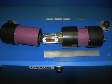
16 BLM Hardware BLM 48 Channel Programmable HV Power Supply front & rear BLM VME Rate detector; Wiggler protection Rapid Access Gamma detector BLM at exit Arc 1

17 Operational Screens High level ops screen Shows Machine Mode & Beam Mode Status of Fast inputs RF & BLMs Shows status of DLPC Drive Laser Pulse Controller Able to adjust current & pulse structure We created the Top 10 List to aid the operator in restoring beam Buttons to get to other relevant screens
18
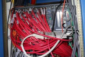
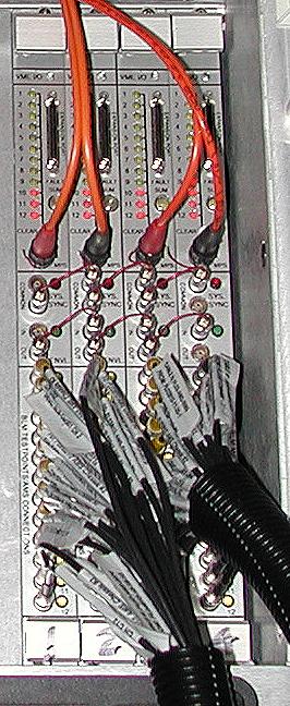
 are the MPS I/O & the other 4 (right) are the BLM boards. All MPS inputs & outputs are done through the P2 connectors.")
. The front panel has the Analog Monitoring System (AMS) and FSD fiber outputs.")
19 VME Hardware The image below is the implementation of the MPS & BML hardware. The 5 VME boards (left side) are the MPS I/O & the other 4 (right) are the BLM boards. All MPS inputs & outputs are done through the P2 connectors. The ribbon cables on the front pass the 3 bit Machine Mode & Beam Modes between cards. The image above is the 12 channel BLM board. The BML connections are on the rear panel (12-9 pin D connectors). The front panel has the Analog Monitoring System (AMS) and FSD fiber outputs. As a diagnostic the gain (HV) can be raised on any tube and monitored in the control room for study of losses.
20 What is the DLPC? Drive Laser Pulse Controller (DLPC) - Integrated Controls Hardware that defines the time structure of electron beam pulses. Micropulse Frequency Electron bunch rep-rate (75 MHz 512 khz) Macropulse Structure Pulse width and frequency micropulse Limited average current as defined by the Machine Protection System (MPS) Remote interface via EPICS control system Slide courtesy Daniel Sexton
21 Design Philosophy The DLPC is treated as two separate systems in the same package that work together but are not dependant on each other. 1. E.O. Cell Pulse Generator Electronics Maximize the flexibility in time structure - rep-rate, pulse width, micropulse frequency, synchronization, etc. Provide other accelerator components beam sync and timing options 2. Average Current Limiting Hardware Operate the given interlock devices - MPS Shutter, ND2 filter, Pockel Cells (E.O.) & others Duty Factor Calculation - Feed forward to inhibit faulting combinations based on E.O. Cell Pulse Generator Slide courtesy Daniel Sexton
22 E.O. Cell Pulse Generator Electronics Line Locked Trigger Source (60Hz) VME Crate Power A simple circuit is attached to an AC source to produce the line-locked 60Hz TTL logic Rep-Rate and Pulse Width Selection F0080 Timing Cards One timing card to handle Pulse Repetition Rate and another to handle Pulse width. Beam Sync, Beam Envelope and Diagnostic Timing F0080 Timing Cards Other timing boards will be used to provide precision delays after beam sync for look ahead triggers and miscellaneous functions. Line-Sync vs. Asynchronous Mode Handled by EPICS As 60Hz will be provided to the Rep-Rate timing card, EPICS can easily notice the desired requests and make the switch transparent One Ping Only Mode Handled by EPICS The timing cards have an external sync input that the Pulse Width card can use a digital I/O bit from EPICS to drive. Micropulse Frequency Conoptics305 A modified 305 is controlled by digital I/O lines to determine the 2^n+1 division of the micropulse frequency. EO-Cell Drivers Conoptics M25Ds The output of the 305 is to 25Ds so the front end EO Cell can gate the laser pulse. Slide courtesy Daniel Sexton External Trigger F0080 Timing Cards A 50 ohm TTL input is available to allow external synchronization and/or triggering from an external source
23 Average Current Limiting Hardware Fiber-Optic Beam Mode Inputs DLPC MPS Board A simple board that converts the 5MHz fiber based permits into TTL logic for the DLPC MPS Board. MPS (Operators) Shutter DLPC MPS Board The MPS Shutter is controlled using a Beamviewer control channel, but the activating signal is interlocked on the DLPC MPS Board ND2 Filter DLPC MPS Board The ND2 filter is also operated by a Beamviewer control channel but insertion of the device is interlocked to the DLPC MPS board Pockels Cell Driver DLPC FSD MPS Board Intercedes Beam Mode 0 Fiber and generates the triggers to open and close the Pockel Cell Fast MPS Shutter DLPC FSD MPS Board Uses the same Beam Mode 0 Fiber to latch the shutter opened or closed depending on the presence of 5MHz fiber signal Peak Detection System Peak Detector Chassis Monitors the IR pulses and closes a fast shutter to protect the SHG Crystal. Includes feed-back and feed-forward systems Slide courtesy Daniel Sexton
24 Drive Laser System Overview Slide courtesy Daniel Sexton
25 DLPC Overview Slide courtesy Daniel Sexton

26 Twin-Shutter Scheme S. Zhang, etc., A simple gating technique for high-average-current photoinjectors, NIMA 629 (2011) 11-15
27 PLC vs VME Our MPS design philosophy has always been to avoid the need for jumpers. This requires the system to be aware of many different classes of devices; some fast some slow. The slow devices are commonly those operated by pneumatic cylinders or motors These limit switches are well suited for interlocking through a PLC Fast devices such as Beam Loss Monitors or loss of RF power require a more prompt response time At the JLab FEL this signal distribution is done by passing 5 MHz on a fiber optic cable (FSD-Fast Shut Down) from device to VME gate array The 5MHz on fiber was partly legacy from existing RF designs & we stuck with it

 that can be replaced by the WAGO DIN mount window comparator ($150 each) This din mount device runs off 24 volts & is ideally suited for connecting to a")
28 Progression to COTS COTS; Commercial-off-the-Shelf 12 years ago I was a skeptic about using PLCs for MPS; I was wrong Or perhaps the recent increases in performance has sold me When I first designed the systems in mid 90s there were a number of interface chassis that we simply designed & built An example of this was the need to know the current in a magnet string; the transducer output was sent to a chassis with a custom designed window comparator which generated the permit signal to be passed on to the VME board Below is the chassis (>$5K) that can be replaced by the WAGO DIN mount window comparator ($150 each) This din mount device runs off 24 volts & is ideally suited for connecting to a PLC
 filters to")

29 Synchrotron Light Monitors SLM ports are installed even in unlikely locations Large dipoles were built with telescopes to bring out light THz chicane has a mirror in vacuum to peek into magnet All locations have insertable neutral density (ND) filters to attenuate signal, SLM bright even at 88MeV pulsed beam OD1 (10x) and OD2 (100x) filters extend dynamic range of cameras 3 orders of magnitude The above image on the left is from Arc 2 with NO Lasing, the right side is the same conditions but with strong Lasing
 BBU (limited")
 Must be able to")

30 Collective Effects ERLs live to generate high brightness, high power beams Collective effects are a logical consequence of that lifestyle JLab systems have been challenged by several effects, including Longitudinal space charge (limited compressed bunch length) BBU (limited current) CSR (potential emittance degradation, heating) Enviromental wakes, resisitive wall, (heating) Larger/brighter systems will be additionally limited by Intrabeam scattering, Touschek effect, beam/gas scattering, ions, (halo formation, beam loss) Must be able to observe, characterize, quantify effects e.g. power into HOMs for BBU Disentangle source of inappropriate behavior e.g. poor dispersion suppression vs. lattice aberration vs. coherent energy shift from CSR Lattice must support diagnosis, control, compensation, and suppression of collective effects
 Initial operation")
31 Coherent Synchrotron Radiation Longitudinal Space Charge 135 pc/0.35 psec bunch ~ 400 A peak current CSR/LSC effects evident Enhanced by parasitic compressions (Bates bend) Initial operation irradiated outcoupler THz heating Use CSR enhancement at tuning cue CSR/LSC
32 Acknowledgements I would like to thank the organizing committee for the opportunity to present the Jlab FEL Team s work! Special thanks to Steve Benson & David Douglas it is a pleasure to work with such insightful people And to our funding agencies Please do not forget us
Jefferson Lab Experience with Beam Halo, Beam Loss, etc.
 Jefferson Lab Experience with Beam Halo, Beam Loss, etc. Pavel Evtushenko with a lot of input from many experienced colleagues Steve Benson, Dave Douglas, Kevin Jordan, Carlos Hernandez-Garcia, Dan Sexton,
JLab 10kW FEL Driver Beam Diagnostics
 JLab 10kW Driver Beam Diagnostics Kevin Jordan, S. V. Benson, J. Coleman, D. Douglas, R. Evans, A. Grippo, D. Gruber, G. Krafft, W. Moore, N. Nishimori, P. Piot, D. Sexton, J. Song and S. Zhang Outline.
TITLE PAGE. Title of paper: PUSH-PULL FEL, A NEW ERL CONCEPT Author: Andrew Hutton. Author Affiliation: Jefferson Lab. Requested Proceedings:
 TITLE PAGE Title of paper: PUSH-PULL FEL, A NEW ERL CONCEPT Author: Andrew Hutton Author Affiliation: Jefferson Lab Requested Proceedings: Unique Session ID: Classification Codes: Keywords: Energy Recovery,
An Overview of Beam Diagnostic and Control Systems for AREAL Linac
 An Overview of Beam Diagnostic and Control Systems for AREAL Linac Presenter G. Amatuni Ultrafast Beams and Applications 04-07 July 2017, CANDLE, Armenia Contents: 1. Current status of existing diagnostic
An Operational Diagnostic Complement for Positrons at CEBAF/JLab
 An Operational Diagnostic Complement for Positrons at CEBAF/JLab Michael Tiefenback JLab, CASA International Workshop on Physics with Positrons at Jefferson Lab 12-15 September 2017 Operating CEBAF with
The basic parameters of the pre-injector are listed in the Table below. 100 MeV
 3.3 The Pre-injector The high design brightness of the SLS requires very high phase space density of the stored electrons, leading to a comparatively short lifetime of the beam in the storage ring. This,
Development of BPM Electronics at the JLAB FEL
 Development of BPM Electronics at the JLAB FEL D. Sexton, P. Evtushenko, K. Jordan, J. Yan, S. Dutton, W. Moore, R. Evans, J. Coleman Thomas Jefferson National Accelerator Facility, Free Electron Laser
PEP II Design Outline
 PEP II Design Outline Balša Terzić Jefferson Lab Collider Review Retreat, February 24, 2010 Outline General Information Parameter list (and evolution), initial design, upgrades Collider Ring Layout, insertions,
High Brightness Injector Development and ERL Planning at Cornell. Charlie Sinclair Cornell University Laboratory for Elementary-Particle Physics
 High Brightness Injector Development and ERL Planning at Cornell Charlie Sinclair Cornell University Laboratory for Elementary-Particle Physics June 22, 2006 JLab CASA Seminar 2 Background During 2000-2001,
IOT OPERATIONAL EXPERIENCE ON ALICE AND EMMA AT DARESBURY LABORATORY
 IOT OPERATIONAL EXPERIENCE ON ALICE AND EMMA AT DARESBURY LABORATORY A. Wheelhouse ASTeC, STFC Daresbury Laboratory ESLS XVIII Workshop, ELLETRA 25 th 26 th November 2010 Contents Brief Description ALICE
Performance of a DC GaAs photocathode gun for the Jefferson lab FEL
 Nuclear Instruments and Methods in Physics Research A 475 (2001) 549 553 Performance of a DC GaAs photocathode gun for the Jefferson lab FEL T. Siggins a, *, C. Sinclair a, C. Bohn b, D. Bullard a, D.
Digital BPMs and Orbit Feedback Systems
 Digital BPMs and Orbit Feedback Systems, M. Böge, M. Dehler, B. Keil, P. Pollet, V. Schlott Outline stability requirements at SLS storage ring digital beam position monitors (DBPM) SLS global fast orbit
The FLASH objective: SASE between 60 and 13 nm
 Injector beam control studies winter 2006/07 talk from E. Vogel on work performed by W. Cichalewski, C. Gerth, W. Jalmuzna,W. Koprek, F. Löhl, D. Noelle, P. Pucyk, H. Schlarb, T. Traber, E. Vogel, FLASH
G0 Laser Status Parity Controls Injector Diagnostics
 G0 Laser Status Parity Controls Injector Diagnostics G0 Collaboration Mtg Jefferson Lab August 16, 2002 G0 Collaboration Mtg (August 16, 2002), 1 Installed new AOM homebuilt laser G0 Collaboration Mtg
Experience with the Cornell ERL Injector SRF Cryomodule during High Beam Current Operation
 Experience with the Cornell ERL Injector SRF Cryomodule during High Beam Current Operation Matthias Liepe Assistant Professor of Physics Cornell University Experience with the Cornell ERL Injector SRF
North Damping Ring RF
 North Damping Ring RF North Damping Ring RF Outline Overview High Power RF HVPS Klystron & Klystron EPICS controls Cavities & Cavity Feedback SCP diagnostics & displays FACET-specific LLRF LLRF distribution
Summary report on synchronization, diagnostics and instrumentation
 Summary report on synchronization, diagnostics and instrumentation A.P. Freyberger and G.A. Krafft Jefferson Lab, 12000 Jefferson Avenue, Newport News, VA. 23606 Abstract The proceedings of Working Group
RUNNING EXPERIENCE OF FZD SRF PHOTOINJECTOR
 RUNNING EXPERIENCE OF FZD SRF PHOTOINJECTOR Rong Xiang On behalf of the BESSY-DESY-FZD-MBI collaboration and the ELBE team FEL 2009, Liverpool, United Kingdom, August 23 ~ 28, 2009 Outline Introduction
The PEFP 20-MeV Proton Linear Accelerator
 Journal of the Korean Physical Society, Vol. 52, No. 3, March 2008, pp. 721726 Review Articles The PEFP 20-MeV Proton Linear Accelerator Y. S. Cho, H. J. Kwon, J. H. Jang, H. S. Kim, K. T. Seol, D. I.
Status of the X-ray FEL control system at SPring-8
 Status of the X-ray FEL control system at SPring-8 T.Fukui 1, T.Hirono 2, N.Hosoda 1, M.Ishii 2, M.Kitamura 1 H.Maesaka 1,T.Masuda 2, T.Matsushita 2, T.Ohata 2, Y.Otake 1, K.Shirasawa 1,M.Takeuchi 2, R.Tanaka
P. Emma, et al. LCLS Operations Lectures
 P. Emma, et al. LCLS Operations Lectures LCLS 1 LCLS Accelerator Schematic 6 MeV 135 MeV 250 MeV σ z 0.83 mm σ z 0.83 mm σ z 0.19 mm σ δ 0.05 % σ δ 0.10 % σ δ 1.6 % Linac-0 L =6 m rf gun L0-a,b Linac-1
Photo cathode RF gun -
 Photo cathode RF gun - *),,, ( 05 Nov. 2004 Spring8 UTNL Linac & Mg Photocathode RF Gun Mg photocathode NERL, 18 MeV Linac and the RF gun Electron Beam Mg photocathode Mg photocathode RF gun of SPring8
New Filling Pattern for SLS-FEMTO
 SLS-TME-TA-2009-0317 July 14, 2009 New Filling Pattern for SLS-FEMTO Natalia Prado de Abreu, Paul Beaud, Gerhard Ingold and Andreas Streun Paul Scherrer Institut, CH-5232 Villigen PSI, Switzerland A new
Beam Diagnostics for the BNL Energy Recovery Linac Test Facility
 Beam Diagnostics for the BNL Energy Recovery Linac Test Facility Peter Cameron, Ilan Ben-Zvi, Michael Blaskiewicz, Michael Brennan, Roger Connolly, William Dawson, Chris Degen, Al DellaPenna, David Gassner,
CLIC Feasibility Demonstration at CTF3
 CLIC Feasibility Demonstration at CTF3 Roger Ruber Uppsala University, Sweden, for the CLIC/CTF3 Collaboration http://cern.ch/clic-study LINAC 10 MO303 13 Sep 2010 The Key to CLIC Efficiency NC Linac for
Non-Invasive Energy Spread Monitoring for the JLAB Experimental Program via Synchrotron Light Interferometers
 Non-Invasive for the JLAB Experimental Program via Synchrotron Light Interferometers P. Chevtsov, T. Day, A.P. Freyberger, R. Hicks Jefferson Lab J.-C. Denard Synchrotron SOLEIL 20th March 2005 1. Energy
Activities on FEL Development and Application at Kyoto University
 Activities on FEL Development and Application at Kyoto University China-Korea-Japan Joint Workshop on Electron / Photon Sources and Applications Dec. 2-3, 2010 @ SINAP, Shanghai Kai Masuda Inst. Advanced
LCLS RF Reference and Control R. Akre Last Update Sector 0 RF and Timing Systems
 LCLS RF Reference and Control R. Akre Last Update 5-19-04 Sector 0 RF and Timing Systems The reference system for the RF and timing starts at the 476MHz Master Oscillator, figure 1. Figure 1. Front end
News from HZB / BESSY Wolfgang Anders at ESLS-RF Meeting September 2010 Trieste
 News from HZB / BESSY Wolfgang Anders at ESLS-RF Meeting September 2010 Trieste Outline Status Klystrons / IOT Modifications of transmitters New LINAC for BESSY II Status BERLinPro HoBiCaT Extension --
Design Studies For The LCLS 120 Hz RF Gun Injector
 BNL-67922 Informal Report LCLS-TN-01-3 Design Studies For The LCLS 120 Hz RF Gun Injector X.J. Wang, M. Babzien, I. Ben-Zvi, X.Y. Chang, S. Pjerov, and M. Woodle National Synchrotron Light Source Brookhaven
The Elettra Storage Ring and Top-Up Operation
 The Elettra Storage Ring and Top-Up Operation Emanuel Karantzoulis Past and Present Configurations 1994-2007 From 2008 5000 hours /year to the users 2010: Operations transition year Decay mode, 2 GeV (340mA)
30 GHz Power Production / Beam Line
 30 GHz Power Production / Beam Line Motivation & Requirements Layout Power mode operation vs. nominal parameters Beam optics Achieved performance Problems Beam phase switch for 30 GHz pulse compression
Development of an Abort Gap Monitor for High-Energy Proton Rings *
 Development of an Abort Gap Monitor for High-Energy Proton Rings * J.-F. Beche, J. Byrd, S. De Santis, P. Denes, M. Placidi, W. Turner, M. Zolotorev Lawrence Berkeley National Laboratory, Berkeley, USA
SPEAR 3: Operations Update and Impact of Top-Off Injection
 SPEAR 3: Operations Update and Impact of Top-Off Injection R. Hettel for the SSRL ASD 2005 SSRL Users Meeting October 18, 2005 SPEAR 3 Operations Update and Development Plans Highlights of 2005 SPEAR 3
Future Performance of the LCLS
 Future Performance of the LCLS J. Welch for many* SLAC National Accelerator Laboratory FLS 2010, ICFA Beam Dynamics Workshop on Future Light Sources, March 1-5, 2010. SLAC National Accelerator Laboratory,
Hall-B Beamline Commissioning Plan for CLAS12
 Hall-B Beamline Commissioning Plan for CLAS12 Version 1.5 S. Stepanyan December 19, 2017 1 Introduction The beamline for CLAS12 utilizes the existing Hall-B beamline setup with a few modifications and
4.9 BEAM BLANKING AND PULSING OPTIONS
 4.9 BEAM BLANKING AND PULSING OPTIONS Beam Blanker BNC DESCRIPTION OF BLANKER CONTROLS Beam Blanker assembly Electron Gun Controls Blanker BNC: An input BNC on one of the 1⅓ CF flanges on the Flange Multiplexer
Linac-Beam Characterizations at 600 MeV Using Optical Transition Radiation Diagnostics *
 Linac-Beam Characterizations at 6 MeV Using Optical Transition Radiation Diagnostics * A. H. Lumpkin, W. J. Berg, B. X. Yang, and M. White Advanced Photon Source, Argonne National Laboratory 97 South Cass
Beam Instrumentation for X-ray FELs
 Beam Instrumentation for X-ray FELs 05/16/2011 1 1 Outline X-ray FEL overview Diagnostics requirements for X-ray FELs Transverse Diagnostics Longitudinal Diagnostics Summary 2 2 X-ray FEL Overview 100
Linac 4 Instrumentation K.Hanke CERN
 Linac 4 Instrumentation K.Hanke CERN CERN Linac 4 PS2 (2016?) SPL (2015?) Linac4 (2012) Linac4 will first inject into the PSB and then can be the first element of a new LHC injector chain. It will increase
Application Note #63 Field Analyzers in EMC Radiated Immunity Testing
 Application Note #63 Field Analyzers in EMC Radiated Immunity Testing By Jason Galluppi, Supervisor Systems Control Software In radiated immunity testing, it is common practice to utilize a radio frequency
TWO BUNCHES WITH NS-SEPARATION WITH LCLS*
 TWO BUNCHES WITH NS-SEPARATION WITH LCLS* F.-J. Decker, S. Gilevich, Z. Huang, H. Loos, A. Marinelli, C.A. Stan, J.L. Turner, Z. van Hoover, S. Vetter, SLAC, Menlo Park, CA 94025, USA Abstract The Linac
LCLS Injector Technical Review
 LCLS Injector Technical Review Stanford Linear Accelerator Center November 3&4 2003 Review Committee Members: Prof. Patrick O Shea Chair University of Maryland Dr. E. Colby Stanford Linear Accelerator
Beam Losses During LCLS Injector Phase-1 1 Operation
 Beam Losses During LCLS Injector Phase-1 1 Operation & Paul Emma September 28, 2006 Radiation Safety Committee Review Scope of Phase 1 Operation Request for Three Operating Modes Operating Plan for Phase
AN OPTICAL AND TERAHERTZ INSTRUMENTATION SYSTEM AT THE FAST LINAC AT FERMILAB*
 FERMILAB-CONF-17-369-AD AN OPTICAL AND TERAHERTZ INSTRUMENTATION SYSTEM AT THE FAST LINAC AT FERMILAB* R. Thurman-Keup, A. H. Lumpkin, J. Thangaraj, FNAL, Batavia, IL, 60510, USA Abstract FAST is a facility
LHC Beam Instrumentation Further Discussion
 LHC Beam Instrumentation Further Discussion LHC Machine Advisory Committee 9 th December 2005 Rhodri Jones (CERN AB/BDI) Possible Discussion Topics Open Questions Tune measurement base band tune & 50Hz
ANKA Status Report. N.Smale, A.-S. Müller, E. Huttel, M.Schuh Slides courtesy of A.-S. Müller and C.Heske.
 ANKA Status Report N.Smale, A.-S. Müller, E. Huttel, M.Schuh Slides courtesy of A.-S. Müller and C.Heske. KIT - University of the State of Baden-Wuerttemberg and National Laboratory of the Helmholtz Association
Drive Laser Operations
 Drive-Laser Operations Drive Laser Thales laser Transport system Recent Laser Milestones Safety Technical Where do we stand today? Laser Acceptance Status Laser Commissioning UV on cathode Injector Commissioning
ARIEL e-linac Machine Protection System Requirements
 TRIUMF Document-85636 ARIEL e-linac Machine Protection System Requirements Document Type: Requirement (Specifications) Release: 02 Release Date: 2013/06/17 Author(s): Shane Koscielniak Note: Before using
Summary of the 1 st Beam Line Review Meeting Injector ( )
") Summary of the 1 st Beam Line Review Meeting Injector (23.10.2006) 15.11.2006 Review the status of: beam dynamics understanding and simulations completeness of beam line description conceptual design of
Summary of the 1 st Beam Line Review Meeting Injector (23.10.2006) 15.11.2006 Review the status of: beam dynamics understanding and simulations completeness of beam line description conceptual design of
TESLA FEL-Report
 Determination of the Longitudinal Phase Space Distribution produced with the TTF Photo Injector M. Geitz a,s.schreiber a,g.von Walter b, D. Sertore a;1, M. Bernard c, B. Leblond c a Deutsches Elektronen-Synchrotron,
2008 JINST 3 S LHC Machine THE CERN LARGE HADRON COLLIDER: ACCELERATOR AND EXPERIMENTS. Lyndon Evans 1 and Philip Bryant (editors) 2
 2") PUBLISHED BY INSTITUTE OF PHYSICS PUBLISHING AND SISSA RECEIVED: January 14, 2007 REVISED: June 3, 2008 ACCEPTED: June 23, 2008 PUBLISHED: August 14, 2008 THE CERN LARGE HADRON COLLIDER: ACCELERATOR AND
PUBLISHED BY INSTITUTE OF PHYSICS PUBLISHING AND SISSA RECEIVED: January 14, 2007 REVISED: June 3, 2008 ACCEPTED: June 23, 2008 PUBLISHED: August 14, 2008 THE CERN LARGE HADRON COLLIDER: ACCELERATOR AND
Current status of XFEL/SPring-8 project and SCSS test accelerator
 Current status of XFEL/SPring-8 project and SCSS test accelerator Takahiro Inagaki for XFEL project in SPring-8 inagaki@spring8.or.jp Outline (1) Introduction (2) Key technology for compactness (3) Key
EUROFEL-Report-2007-DS EUROPEAN FEL Design Study
 EUROFEL-Report-2007-DS4-095 EUROPEAN FEL Design Study Deliverable N : D 4.3 Deliverable Title: Task: Authors: Generation of 3rd harmonic photons at 90 nm DS-4 see next page Contract N : 011935 Project
Low Level RF for PIP-II. Jonathan Edelen LLRF 2017 Workshop (Barcelona) 16 Oct 2017
 16 Oct 2017") Low Level RF for PIP-II Jonathan Edelen LLRF 2017 Workshop (Barcelona) 16 Oct 2017 PIP-II LLRF Team Fermilab Brian Chase, Edward Cullerton, Joshua Einstein, Jeremiah Holzbauer, Dan Klepec, Yuriy Pischalnikov,
Low Level RF for PIP-II Jonathan Edelen LLRF 2017 Workshop (Barcelona) 16 Oct 2017 PIP-II LLRF Team Fermilab Brian Chase, Edward Cullerton, Joshua Einstein, Jeremiah Holzbauer, Dan Klepec, Yuriy Pischalnikov,
Compact, e-beam based mm-and THzwave light sources
 Compact, e-beam based mm-and THzwave light sources S.G. Biedron, S.V. Milton (CSU) and G.P. Gallerano (ENEA) Frontiers of THz Science Workshop Sept. 5-6, 2012 SLAC 1 Collaborators involved with the enclosed
3 cerl. 3-1 cerl Overview. 3-2 High-brightness DC Photocathode Gun and Gun Test Beamline
 3 cerl 3-1 cerl Overview As described before, the aim of the cerl in the R&D program includes the development of critical components for the ERL, as well as the construction of a test accelerator. The
Report on the LCLS Injector Technical Review
 Report on the LCLS Injector Technical Review Stanford Linear Accelerator Center November 3&4, 2003 Committee Members Prof. Patrick G. O Shea, Chair, University of Maryland Dr. Eric Colby, Stanford Linear
RF considerations for SwissFEL
 RF considerations for H. Fitze in behalf of the PSI RF group Workshop on Compact X-Ray Free Electron Lasers 19.-21. July 2010, Shanghai Agenda Introduction RF-Gun Development C-band development Summary
Operation of CEBAF photoguns at average beam current > 1 ma
 Operation of CEBAF photoguns at average beam current > 1 ma M. Poelker, J. Grames, P. Adderley, J. Brittian, J. Clark, J. Hansknecht, M. Stutzman Can we improve charge lifetime by merely increasing the
GFT Channel Digital Delay Generator
 Features 20 independent delay Channels 100 ps resolution 25 ps rms jitter 10 second range Output pulse up to 6 V/50 Ω Independent trigger for every channel Fours Triggers Three are repetitive from three
LLRF at SSRF. Yubin Zhao
 LLRF at SSRF Yubin Zhao 2017.10.16 contents SSRF RF operation status Proton therapy LLRF Third harmonic cavity LLRF Three LINAC LLRF Hard X FEL LLRF (future project ) Trip statistics of RF system Trip
4.4 Injector Linear Accelerator
 4.4 Injector Linear Accelerator 100 MeV S-band linear accelerator based on the components already built for the S-Band Linear Collider Test Facility at DESY [1, 2] will be used as an injector for the CANDLE
Tutorial: Trak design of an electron injector for a coupled-cavity linear accelerator
 Tutorial: Trak design of an electron injector for a coupled-cavity linear accelerator Stanley Humphries, Copyright 2012 Field Precision PO Box 13595, Albuquerque, NM 87192 U.S.A. Telephone: +1-505-220-3975
Week 0: PPS Certification and Processing. Mon Feb 11 Tue Feb 12 Wed Feb 13 Thu Feb 14 Fri Feb 15 Sat Feb 16 Sun Feb 17
 Week 0: PPS Certification and Processing Mon Feb 11 Tue Feb 12 Wed Feb 13 Thu Feb 14 Fri Feb 15 Sat Feb 16 Sun Feb 17 Work in tunnel Work in tunnel PPS Certification PPS Certification PPS Certification
Simulations on Beam Monitor Systems for Longitudinal Feedback Schemes at FLASH.
 Simulations on Beam Monitor Systems for Longitudinal Feedback Schemes at FLASH. Christopher Behrens for the FLASH team Deutsches Elektronen-Synchrotron (DESY) FLS-2010 Workshop at SLAC, 4. March 2010 C.
PROJECT DESCRIPTION. Longitudinal phase space monitors for the ILC injectors and bunch compressors
 PROJECT DESCRIPTION Longitudinal phase space monitors for the ILC injectors and bunch compressors Personnel and Institution(s) requesting funding Philippe Piot Northern Illinois University Dept of Physics,
Screen investigations for low energetic electron beams at PITZ
 1 Screen investigations for low energetic electron beams at PITZ S. Rimjaem, J. Bähr, H.J. Grabosch, M. Groß Contents Review of PITZ setup Screens and beam profile monitors at PITZ Test results Summary
Accelerator Instrumentation RD. Monday, July 14, 2003 Marc Ross
 Monday, Marc Ross Linear Collider RD Most RD funds address the most serious cost driver energy The most serious impact of the late technology choice is the failure to adequately address luminosity RD issues
PHOTOTUBE SCANNING SETUP AT THE UNIVERSITY OF MARYLAND. Doug Roberts U of Maryland, College Park
 PHOTOTUBE SCANNING SETUP AT THE UNIVERSITY OF MARYLAND Doug Roberts U of Maryland, College Park Overview We have developed a system for measuring and scanning phototubes for the FDIRC Based primarily on
MULTIDYNE INNOVATIONS IN TELEVISION TESTING & DISTRIBUTION DIGITAL VIDEO, AUDIO & DATA FIBER OPTIC MULTIPLEXER TRANSPORT SYSTEM
 MULTIDYNE INNOVATIONS IN TELEVISION TESTING & DISTRIBUTION INSTRUCTION MANUAL DVM-1000 DIGITAL VIDEO, AUDIO & DATA FIBER OPTIC MULTIPLEXER TRANSPORT SYSTEM MULTIDYNE Electronics, Inc. Innovations in Television
Noise Detector ND-1 Operating Manual
 Noise Detector ND-1 Operating Manual SPECTRADYNAMICS, INC 1849 Cherry St. Unit 2 Louisville, CO 80027 Phone: (303) 665-1852 Fax: (303) 604-6088 Table of Contents ND-1 Description...... 3 Safety and Preparation
CBF500 High resolution Streak camera
 High resolution Streak camera Features 400 900 nm spectral sensitivity 5 ps impulse response 10 ps trigger jitter Trigger external or command 5 to 50 ns analysis duration 1024 x 1024, 12-bit readout camera
Characterizing Transverse Beam Dynamics at the APS Storage Ring Using a Dual-Sweep Streak Camera
 Characterizing Transverse Beam Dynamics at the APS Storage Ring Using a Dual-Sweep Streak Camera Bingxin Yang, Alex H. Lumpkin, Katherine Harkay, Louis Emery, Michael Borland, and Frank Lenkszus Advanced
Undulator Protection for FLASH and for the European XFEL
 Undulator Protection for FLASH and for the European FLASH sacrificial undulator: beam loss simulations FLASH BLM system plans FLASH sacrificial undulator FLASH Collimators BC2 scraper gun collimator (Ø
CEBAF Accelerator Update. Michael Tiefenback CASA Accelerator Physics Experimental Liaison June 14, 2017
 CEBAF Accelerator Update Michael Tiefenback CASA Accelerator Physics Experimental Liaison June 14, 2017 CLAS12 Collaboration Meeting, June 13-16, 2017 1 Accelerator Division Leadership On April 30 Andrew
Beam Instrumentation for CTF3 and CLIC
 Beam Instrumentation for CTF3 and CLIC Beam loss - Beam halo monitoring developments CLIC diagnostic Common developments with other projects Specific requirements for CLIC Beam Loss and Beam Halo measurement
Top-Up Experience at SPEAR3
 Top-Up Experience at SPEAR3 Contents SPEAR 3 and the injector Top-up requirements Hardware systems and modifications Safety systems & injected beam tracking Interlocks & Diagnostics SPEAR3 Accelerator
PEP-II longitudinal feedback and the low groupdelay. Dmitry Teytelman
 PEP-II longitudinal feedback and the low groupdelay woofer Dmitry Teytelman 1 Outline I. PEP-II longitudinal feedback and the woofer channel II. Low group-delay woofer topology III. Why do we need a separate
High Rep Rate Guns: FZD Superconducting RF Photogun
 High Rep Rate Guns: FZD Superconducting RF Photogun J. Teichert, A. Arnold, H. Büttig, D. Janssen, M. Justus, U. Lehnert, P. Michel, K. Moeller, P. Murcek, Ch. Schneider, R. Schurig, G. Staats, F. Staufenbiel,
Status of BESSY II and berlinpro. Wolfgang Anders. Helmholtz-Zentrum Berlin for Materials and Energy (HZB) 20th ESLS-RF Meeting
 20th ESLS-RF Meeting") Status of BESSY II and berlinpro Wolfgang Anders Helmholtz-Zentrum Berlin for Materials and Energy (HZB) 20th ESLS-RF Meeting 16.-17.11.2016 at PSI Outline BESSY II Problems with circulators Landau cavity
Status of BESSY II and berlinpro Wolfgang Anders Helmholtz-Zentrum Berlin for Materials and Energy (HZB) 20th ESLS-RF Meeting 16.-17.11.2016 at PSI Outline BESSY II Problems with circulators Landau cavity
Users Manual FWI HiDef Sync Stripper
 Users Manual FWI HiDef Sync Stripper Allows "legacy" motion control and film synchronizing equipment to work with modern HDTV cameras and monitors providing Tri-Level sync signals. Generates a film-camera
DARK CURRENT IN SUPERCONDUCTING RF PHOTOINJECTORS MEASUREMENTS AND MITIGATION
 DARK CURRENT IN SUPERCONDUCTING RF PHOTOINJECTORS MEASUREMENTS AND MITIGATION J. Teichert #, A. Arnold, P. Murcek, G. Staats, R. Xiang, HZDR, Dresden, Germany P. Lu, H. Vennekate, HZDR & Technische Universität,
Beam Loss Detection for MPS at FRIB
 Beam Loss Detection for MPS at FRIB Zhengzheng Liu Beam Diagnostics Physicist This material is based upon work supported by the U.S. Department of Energy Office of Science under Cooperative Agreement DE-SC0000661.
Status of the Jefferson Lab Polarized Beam Physics Program and Preparations for Upcoming Parity Experiments
 Status of the Jefferson Lab Polarized Beam Physics Program and Preparations for Upcoming Parity Experiments P. Adderley, M. Baylac, J. Clark, A. Day, J. Grames, J. Hansknecht, M. Poelker, M. Stutzman PESP
KARA and FLUTE RF Overview/status
 KARA and FLUTE RF Overview/status Nigel Smale on behalf of IBPT and LAS teams Laboratory for Applications of Synchrotron radiation (LAS) Institute for Beam Physics and Technology (IBPT) KARA KIT The Research
Status of SOLARIS Arkadiusz Kisiel
 Status of SOLARIS Arkadiusz Kisiel Solaris National Synchrotron Light Source Jagiellonian University Czerwone Maki 98 30-392 Kraków www.synchrotron.uj.edu.pl Arkadiusz.Kisiel@uj.edu.pl On behalf of SOLARIS
Detailed Design Report
 Detailed Design Report Chapter 4 MAX IV Injector 4.6. Acceleration MAX IV Facility CHAPTER 4.6. ACCELERATION 1(10) 4.6. Acceleration 4.6. Acceleration...2 4.6.1. RF Units... 2 4.6.2. Accelerator Units...
HPS Slow Controls Overview
 HPS Slow Controls Overview Hovanes Egiyan 6/18/2014 Hovanes Egiyan HPS Collaboration Meeting 1 Content Introduction HPS SVT Controls ECAL Controls Hall B controls Summary 6/18/2014 Hovanes Egiyan HPS Collaboration
Features of the 745T-20C: Applications of the 745T-20C: Model 745T-20C 20 Channel Digital Delay Generator
 20 Channel Digital Delay Generator Features of the 745T-20C: 20 Independent delay channels - 100 ps resolution - 25 ps rms jitter - 10 second range Output pulse up to 6 V/50 Ω Independent trigger for every
A Cathode Development Cornell Cultera This scope includes all labor and purchases required produce photocathodes required by CBETA.
 A1.01 PROJECT MANAGEMENT BNL/Cornell Michnoff A1.01.01 Milestones BNL/Cornell Michnoff This scope is a placeholder for all project high level milestones for NYSERDA. There is no cost or labor related to
Challenges in Accelerator Beam Instrumentation
 Proceedings of the DPF-2009 Conference, Detroit, MI, July 27-31, 2009 1 Challenges in Accelerator Beam Instrumentation M. Wendt Fermi National Accelerator Laboratory, Batavia, IL 60510, USA The challenges
COMMISSIONING OF A DUAL-SWEEP STREAK CAMERA WITH APPLICATIONS TO THE ASTA PHOTOINJECTOR DRIVE LASER*
 COMMISSIONING OF A DUAL-SWEEP STREAK CAMERA WITH APPLICATIONS TO THE ASTA PHOTOINJECTOR DRIVE LASER* A. H. Lumpkin #, D. Edstrom, J. Ruan, and J. Santucci Fermi National Accelerator Laboratory, Batavia,
Klystron Lifetime Management System
 Klystron Lifetime Management System Łukasz Butkowski Vladimir Vogel FLASH Seminar Outline 2 Introduction to KLM Protection and measurement functions Installation at Klystron test stand FPGA implementation
14 GHz, 2.2 kw KLYSTRON GENERATOR GKP 22KP 14GHz WR62 3x400V
 14 GHz, 2.2 kw KLYSTRON GENERATOR GKP 22KP 14GHz WR62 3x400V With its characteristics of power stability independent of the load, very fast response time when pulsed (via external modulated signal), low
THE NEW LASER FAMILY FOR FINE WELDING FROM FIBER LASERS TO PULSED YAG LASERS
 FOCUS ON FINE SOLUTIONS THE NEW LASER FAMILY FOR FINE WELDING FROM FIBER LASERS TO PULSED YAG LASERS Welding lasers from ROFIN ROFIN s laser sources for welding satisfy all criteria for the optimized laser
STATUS AND COMMISSIONING RESULTS OF THE R&D ERL AT BNL*
 STATUS AND COMMISSIONING RESULTS OF THE R&D ERL AT BNL* D. Kayran #,1,2, Z. Altinbas 1, D. Beavis 1, S. Belomestnykh 1,2, I. Ben-Zvi 1,2, S. Deonarine 1, D.M. Gassner 1, R. C. Gupta 1, H. Hahn 1,L.R. Hammons
National Park Service Photo. Utah 400 Series 1. Digital Routing Switcher.
 National Park Service Photo Utah 400 Series 1 Digital Routing Switcher Utah Scientific has been involved in the design and manufacture of routing switchers for audio and video signals for over thirty years.
Status of Elettra, top-up and other upgrades
 Status of Elettra, top-up and other upgrades Emanuel Karantzoulis ELETTRA / Trieste, Italy / 2010 November 25-26 Past and Present Configurations 1994-2007 From 2008 No full energy injection Full energy
Photoinjector Laser Operation and Cathode Performance
 Photoinjector Laser Operation and Cathode Performance Daniele Sertore, INFN Milano LASA Siegfried Schreiber, DESY Laser operational experience Laser beam properties Cathode performances Outlook TTF and