North Damping Ring RF
|
|
|
- Ethelbert Hood
- 5 years ago
- Views:
Transcription
1 North Damping Ring RF
2 North Damping Ring RF Outline Overview High Power RF HVPS Klystron & Klystron EPICS controls Cavities & Cavity Feedback SCP diagnostics & displays FACET-specific LLRF LLRF distribution RF Feedbacks: RF scope (TEK scope) Feedback triggers Tuning tips
3 System Overview: Purpose From P. Krejcik s Damping Rings RF Users Guide The RF system provides a synchronous accelerating voltage to make up for the energy individual particles lose due to synchrotron radiation and the energy a bunch can lose from higher order mode losses. In addition, the RF provides a longitudinal restoring force that keeps the particles bunched together inside the RF bucket.
4 Some Damping Ring Paramters Beam Energy 1.19 GeV RF Frequency 714 MHz Revolution Frequency 8.50 MHz Harmonic number (buckets) 84 Energy Lossper Turn Either 93.1 kevor 79.2 kev? RF voltage 800 kv Phase 6.7 Synchrotron Frequency khz Storage Time 16.6 ms Available Klystron Power 50 kw Bunch Length 5.25 mm (4.5 of 714 MHz) Energy damping time 1.78 msec Horizontal damping time 3.5 msec Vertical damping time 3.53 msec Pi mode cavity damping time 100 μsec

5 High Power RF


6 HVPS SLAC-built CW klystron, no modulator, no VVS. No PIOP, just DAC/SAM readout in SCP On/off control only, through EPICS
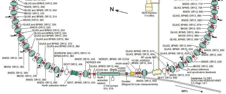
7 NDR Klystron One CW klystron, located inside the vault, SE corner. Capable of 60 kw peak AMRF sets voltage locally, usually ~800 kv, designed to be capable of >1MV Klystron has no PPS interlocks Two cavities driven through isolator and magic tee to prevent reflected power from the cavities from reaching the klystron
8 NDR Klystron Controls Klystron Mode: OFF: No LLRF TUNE: Allows tuners time to adjust at a lower RF power level OPER: Running with full gap voltage To reset after a trip: Clear interlocks, turn on HVPS, Change modes from off to tune, wait until cavities turn green, change mode to operate.
9 RF cavities RF Cavity 590 Two cavities, two cells in each. Unit numbers 590 (Cavity A) and 810 (Cavity B) Cavity tuners : mechanical plungers moved by stepper motors Tuner feedback controls in EPICS
10 RF cavities Cavity tuner feedbacks in EPICS In Automatic, feedback moves the phase loading angle, a phase comparison of the 714 MHz waveguide pickup signal and the cavity pickup signal ~1 Hz feedback In Manual, users have control of the position slider. Option to have the feedback disabled when beam is not present (could prevent tuner from walking away when there is no beam loading)
11 πmode Cavity Passive Cavity, meant to damp πmode oscillations in twobunch operation If the tuner ends up in the wrong place, power can get absorbed, structure heats up, create vacuum problems.
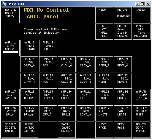
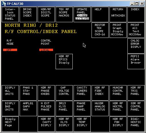
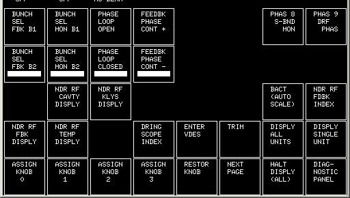
12 Klystron EPICS displays

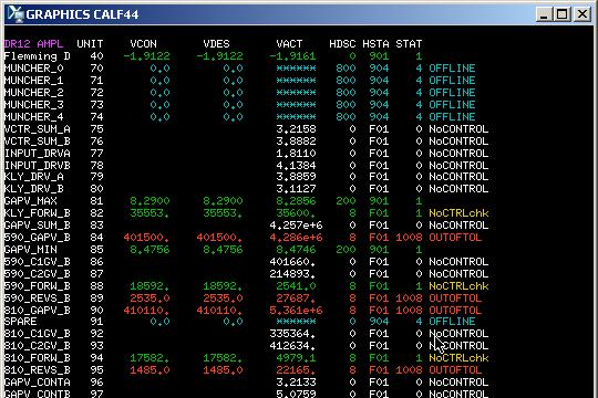
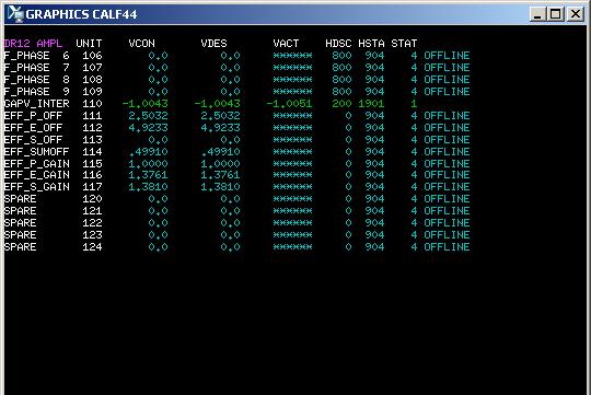
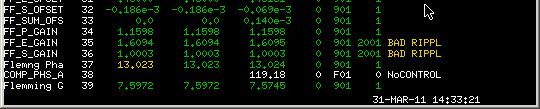
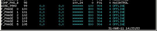
13 SCP displays


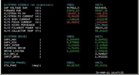
14 Status Displays Update every 2 minutes
15 LLRF Distribution
16 LLRF Distribution Functional Schematic

17 Simplified RF cartoon (SLC era)

18 Simplified RF cartoon (FACETrelevant only)
19 Voltage Control Oscillator Can use to change the frequency of the incoming LLRF Used during comissioning Used during comissioning mostly


20 Station Phase Adjusts phase of the ring RF at injection relative to the injector RF OPS set to maximize OPS set to maximize capture


21 DR RF Feedbacks Most feedbacks are mostly hardware, adjustments need to be made locally.
22 Question for Mike/Howard Does the gap voltage still go to some intermediate value when we rate limit? Does this attenuator thing that was part of the feedback that we are no longer using do that?
23 Beam Phase detectors 714 and 2856 MHz phase detectors The signal from a BPM pumps an LC circuit, phase of oscillation changes when the beam phase changes.
24 S-Band Phase Loop Phase locks the phase of the damping ring beam to the S-Band phase of sector 2 (and NRTL compressor) Gated: switches on 1.3 ms after injection and then ramps to the desired extraction phase. Makes extraction phase independent of injector phase drifts The change in phase is calculated by the DROPP camacmodule, which has triggers for start and stop times and calculates an appropriate ramp. S-Band desired phase setpointis set by Phase Ramp NREX feedback actuator is an offset to the S-Band feedback


25 Phase Ramp Reference phase at the end of the phase ramp prior to extraction, relative to linac


26 SCP S-Band Feedback Controls

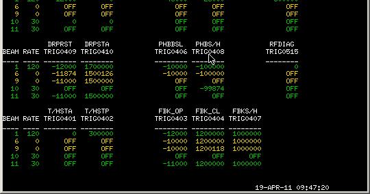
27 S-Band Feedback Triggers


28 Phase Compensation Fbck EPICS feedback, 10 khz Maintains a constant phase between the klystron and cavity. Intended to compensate for power supply variations or phase changes across attenuators used for amplitude control Readbackvalue should normally be zero. If it starts becomes unlocked, it can be reset by opening the loop, adjusting slider until readbackis close to zero, and closing the loop again.
29 Synchrotron Loop Provides external damping of the synchrotron 0-mode bunch oscillations Beam phase is compared to Beam phase is compared to the 714 MHz reference and fedbackto a fast 714 MHz phase shifter
30 Direct loop fbck Many names: Direct Loop, Fleming loop, beam loading feedback MHz feedback. Meant to combat bunch length instability at high current (sawtoothinstability) for SLC (where the bunch would damp to a certain size and then blow up, damp down and blow up) as well as beam-loading transients at injection Adjusts the klystron drive to compensate for the change in beam loading for different bunch lengths. May or may not use for FACET.


31 Status Displays Update every 2 minutes
32 DR TekScope CH1, CH2 can be many things: Beam phase relative to 714 MHz reference or cavity frequency, S-band phase, BPM sum signal peak, cavity gap voltage, etc. HVS thinks remote control doesn t work, so someone will have to drive down, set it up how we want it, and then document which channels are hardwired to which signals.
33 S-Band beam phase 714 MHz beam phase

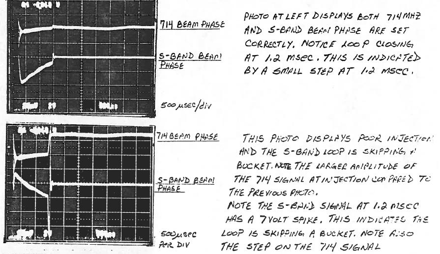
34 RF Scope Images
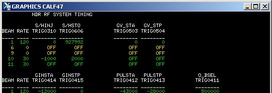
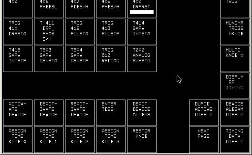
35 RF feedback triggers
36 Tuning/Setup tips To get the first two turns: launch, septum bumps To get multiple turns (up to ~20): make sure tunes are right Can get up to 200 with RF off if the tunes are right, per Lanny Adjust Station Phase (Phas1) for max capture (tweak far enough to both sides to see appreciable loss, leave phase in the middle).
37 The end TBD: Supplimentalstuff about SLC things, references
LCLS RF Reference and Control R. Akre Last Update Sector 0 RF and Timing Systems
 LCLS RF Reference and Control R. Akre Last Update 5-19-04 Sector 0 RF and Timing Systems The reference system for the RF and timing starts at the 476MHz Master Oscillator, figure 1. Figure 1. Front end
ANKA RF System - Upgrade Strategies
 ANKA RF System - Upgrade Strategies Vitali Judin ANKA Synchrotron Radiation Facility 2014-09 - 17 KIT University of the State Baden-Wuerttemberg and National Laboratory of the Helmholtz Association www.kit.edu
PEP II Design Outline
 PEP II Design Outline Balša Terzić Jefferson Lab Collider Review Retreat, February 24, 2010 Outline General Information Parameter list (and evolution), initial design, upgrades Collider Ring Layout, insertions,
Bunch-by-bunch feedback and LLRF at ELSA
 Bunch-by-bunch feedback and LLRF at ELSA Dmitry Teytelman Dimtel, Inc., San Jose, CA, USA February 9, 2010 Outline 1 Feedback Feedback basics Coupled-bunch instabilities and feedback Beam and feedback
Synchrotron Light Facility. Operation of ALBA RF. Angela Salom on behalf of RF team: Francis Perez, Bea Bravo and Jesus Ocampo
 Operation of ALBA RF Angela Salom on behalf of RF team: Francis Perez, Bea Bravo and Jesus Ocampo Outline ALBA RF Overview: Booster and SR RF Operation with beam Statistics of first year operation Cavities
Detailed Design Report
 Detailed Design Report Chapter 4 MAX IV Injector 4.6. Acceleration MAX IV Facility CHAPTER 4.6. ACCELERATION 1(10) 4.6. Acceleration 4.6. Acceleration...2 4.6.1. RF Units... 2 4.6.2. Accelerator Units...
Status of SOLARIS. Paweł Borowiec On behalf of Solaris Team
 Status of SOLARIS Paweł Borowiec On behalf of Solaris Team e-mail: pawel.borowiec@uj.edu.pl XX ESLS-RF Meeting, Villingen 16-17.11.2016 Outline 1. Timeline 2. Injector 3. Storage ring 16-17.11.2016 XX
IOT OPERATIONAL EXPERIENCE ON ALICE AND EMMA AT DARESBURY LABORATORY
 IOT OPERATIONAL EXPERIENCE ON ALICE AND EMMA AT DARESBURY LABORATORY A. Wheelhouse ASTeC, STFC Daresbury Laboratory ESLS XVIII Workshop, ELLETRA 25 th 26 th November 2010 Contents Brief Description ALICE
The PEFP 20-MeV Proton Linear Accelerator
 Journal of the Korean Physical Society, Vol. 52, No. 3, March 2008, pp. 721726 Review Articles The PEFP 20-MeV Proton Linear Accelerator Y. S. Cho, H. J. Kwon, J. H. Jang, H. S. Kim, K. T. Seol, D. I.
KARA and FLUTE RF Overview/status
 KARA and FLUTE RF Overview/status Nigel Smale on behalf of IBPT and LAS teams Laboratory for Applications of Synchrotron radiation (LAS) Institute for Beam Physics and Technology (IBPT) KARA KIT The Research
The Elettra Storage Ring and Top-Up Operation
 The Elettra Storage Ring and Top-Up Operation Emanuel Karantzoulis Past and Present Configurations 1994-2007 From 2008 5000 hours /year to the users 2010: Operations transition year Decay mode, 2 GeV (340mA)
LLRF at SSRF. Yubin Zhao
 LLRF at SSRF Yubin Zhao 2017.10.16 contents SSRF RF operation status Proton therapy LLRF Third harmonic cavity LLRF Three LINAC LLRF Hard X FEL LLRF (future project ) Trip statistics of RF system Trip
Scavenger Extraction. Karen Goldsmith Shawn Alverson
 Scavenger Extraction Karen Goldsmith Shawn Alverson Topics Beam line and area maps High Power Target (HPT) How to establish first beam to HPT Setting energy (configs, multiknobs, Fast Phase Shifters, etc.)
Experience with the Cornell ERL Injector SRF Cryomodule during High Beam Current Operation
 Experience with the Cornell ERL Injector SRF Cryomodule during High Beam Current Operation Matthias Liepe Assistant Professor of Physics Cornell University Experience with the Cornell ERL Injector SRF
The FAIR plinac RF Systems
 The FAIR plinac RF Systems Libera Workshop Sep. 2011 Gerald Schreiber Gerald Schreiber, GSI RF Department 2 (1) Overview GSI / FAIR (2) FAIR Proton Linear Accelerator "plinac" (3) plinac RF Systems (4)
4.4 Injector Linear Accelerator
 4.4 Injector Linear Accelerator 100 MeV S-band linear accelerator based on the components already built for the S-Band Linear Collider Test Facility at DESY [1, 2] will be used as an injector for the CANDLE
3 cerl. 3-1 cerl Overview. 3-2 High-brightness DC Photocathode Gun and Gun Test Beamline
 3 cerl 3-1 cerl Overview As described before, the aim of the cerl in the R&D program includes the development of critical components for the ERL, as well as the construction of a test accelerator. The
Status of SOLARIS Arkadiusz Kisiel
 Status of SOLARIS Arkadiusz Kisiel Solaris National Synchrotron Light Source Jagiellonian University Czerwone Maki 98 30-392 Kraków www.synchrotron.uj.edu.pl Arkadiusz.Kisiel@uj.edu.pl On behalf of SOLARIS
SPEAR 3: Operations Update and Impact of Top-Off Injection
 SPEAR 3: Operations Update and Impact of Top-Off Injection R. Hettel for the SSRL ASD 2005 SSRL Users Meeting October 18, 2005 SPEAR 3 Operations Update and Development Plans Highlights of 2005 SPEAR 3
9th ESLS RF Meeting September ALBA RF System. F. Perez. RF System 1/20
 ALBA RF System F. Perez RF System 1/20 ALBA Synchrotron Light Source in Barcelona (Spain) 3 GeV accelerator 30 beamlines (7 on day one) 50-50 Spanish Government Catalan Government First beam for users
PEP-I1 RF Feedback System Simulation
 SLAC-PUB-10378 PEP-I1 RF Feedback System Simulation Richard Tighe SLAC A model containing the fundamental impedance of the PEP- = I1 cavity along with the longitudinal beam dynamics and feedback system
Digital BPMs and Orbit Feedback Systems
 Digital BPMs and Orbit Feedback Systems, M. Böge, M. Dehler, B. Keil, P. Pollet, V. Schlott Outline stability requirements at SLS storage ring digital beam position monitors (DBPM) SLS global fast orbit
RF Power Generation II
 RF Power Generation II Klystrons, Magnetrons and Gyrotrons Professor R.G. Carter Engineering Department, Lancaster University, U.K. and The Cockcroft Institute of Accelerator Science and Technology Scope
Phase (deg) Phase (deg) Positive feedback, 317 ma. Negative feedback, 330 ma. jan2898/1638: beam pseudospectrum around 770*frev.
 Phase (deg) Positive feedback, 317 ma. Negative feedback, 330 ma. jan2898/1638: beam pseudospectrum around 770*frev.") Commissioning Experience from PEP-II HER Longitudinal Feedback 1 S. Prabhakar, D. Teytelman, J. Fox, A. Young, P. Corredoura, and R. Tighe Stanford Linear Accelerator Center, Stanford University, Stanford,
Commissioning Experience from PEP-II HER Longitudinal Feedback 1 S. Prabhakar, D. Teytelman, J. Fox, A. Young, P. Corredoura, and R. Tighe Stanford Linear Accelerator Center, Stanford University, Stanford,
RF PERFORMANCE AND OPERATIONAL ISSUES
 RF PERFORMANCE AND OPERATIONAL ISSUES A. Butterworth, L. Arnaudon, P. Baudrenghien, O. Brunner, E. Ciapala, W. Hofle, J. Molendijk, CERN, Geneva, Switzerland Abstract During the 2009 LHC run, a number
LHC Nominal injection sequence
 LHC Nominal injection sequence Mike Lamont Acknowledgements: Reyes Alemany Fernandez, Brennan Goddard Nominal injection Overall injection scheme Pilot R1, Pilot R2, Intermediate R1 Optimise Intermediate
INFN School on Electron Accelerators. RF Power Sources and Distribution
 INFN School on Electron Accelerators 12-14 September 2007, INFN Sezione di Pisa Lecture 7b RF Power Sources and Distribution Carlo Pagani University of Milano INFN Milano-LASA & GDE The ILC Double Tunnel
The basic parameters of the pre-injector are listed in the Table below. 100 MeV
 3.3 The Pre-injector The high design brightness of the SLS requires very high phase space density of the stored electrons, leading to a comparatively short lifetime of the beam in the storage ring. This,
The ESRF Radio-frequency Data Logging System for Failure Analysis
 The ESRF Radio-frequency Data Logging System for Failure Analysis Jean-Luc REVOL Machine Division European Synchrotron Radiation Facility Accelerator Reliability Workshop 4-6 February 2002 Impact of the
Status and Plans for PEP-II
 Status and Plans for PEP-II John Seeman SLAC Particle and Particle-Astrophysics DOE HEPAP P5 Review April 21, 2006 Topics Luminosity records for PEP-II in October 2005 Fall shut-down upgrades Run 5b turn
Status of BESSY II and berlinpro. Wolfgang Anders. Helmholtz-Zentrum Berlin for Materials and Energy (HZB) 20th ESLS-RF Meeting
 20th ESLS-RF Meeting") Status of BESSY II and berlinpro Wolfgang Anders Helmholtz-Zentrum Berlin for Materials and Energy (HZB) 20th ESLS-RF Meeting 16.-17.11.2016 at PSI Outline BESSY II Problems with circulators Landau cavity
Status of BESSY II and berlinpro Wolfgang Anders Helmholtz-Zentrum Berlin for Materials and Energy (HZB) 20th ESLS-RF Meeting 16.-17.11.2016 at PSI Outline BESSY II Problems with circulators Landau cavity
Low Level RF for PIP-II. Jonathan Edelen LLRF 2017 Workshop (Barcelona) 16 Oct 2017
 16 Oct 2017") Low Level RF for PIP-II Jonathan Edelen LLRF 2017 Workshop (Barcelona) 16 Oct 2017 PIP-II LLRF Team Fermilab Brian Chase, Edward Cullerton, Joshua Einstein, Jeremiah Holzbauer, Dan Klepec, Yuriy Pischalnikov,
Low Level RF for PIP-II Jonathan Edelen LLRF 2017 Workshop (Barcelona) 16 Oct 2017 PIP-II LLRF Team Fermilab Brian Chase, Edward Cullerton, Joshua Einstein, Jeremiah Holzbauer, Dan Klepec, Yuriy Pischalnikov,
Spear3 RF System Sam Park 11/06/2003. Spear3 RF System. High Power Components Operation and Control. RF Requirement.
 Spear3 RF System RF Requirement Overall System High Power Components Operation and Control SPEAR 3 History 1996 Low emittance lattices explored 1996 SPEAR 3 proposed 11/97 SPEAR 3 design study team formed
Modeling and simulation of longitudinal dynamics for Low Energy Ring-High Energy Ring at the Positron-Electron Project 1
 SLAC-PUB-12374 February, 27 Modeling and simulation of longitudinal dynamics for Low Energy Ring-High Energy Ring at the Positron-Electron Project 1 C. Rivetta, T. Mastorides, J. D. Fox, D. Teytelman,
Design and Simulation of High Power RF Modulated Triode Electron Gun. A. Poursaleh
 Design and Simulation of High Power RF Modulated Triode Electron Gun A. Poursaleh National Academy of Sciences of Armenia, Institute of Radio Physics & Electronics, Yerevan, Armenia poursaleh83@yahoo.com
Basic rules for the design of RF Controls in High Intensity Proton Linacs. Particularities of proton linacs wrt electron linacs
 Basic rules Basic rules for the design of RF Controls in High Intensity Proton Linacs Particularities of proton linacs wrt electron linacs Non-zero synchronous phase needs reactive beam-loading compensation
ANKA Status Report. N.Smale, on behalf of all ANKA colleagues, Directors : A.-S. Müller, C Heske, T Baumbach.
 ANKA Status Report N.Smale, on behalf of all ANKA colleagues, Directors : A.-S. Müller, C Heske, T Baumbach. Institute for Synchrotron Radiation KIT - University of the State of Baden-Wuerttemberg and
Top-Up Experience at SPEAR3
 Top-Up Experience at SPEAR3 Contents SPEAR 3 and the injector Top-up requirements Hardware systems and modifications Safety systems & injected beam tracking Interlocks & Diagnostics SPEAR3 Accelerator
INTRODUCTION. SLAC-PUB-8414 March 2000
 SLAC-PUB-8414 March 2 Beam Diagnostics Based on Time-Domain Bunch-by-Bunch Data * D. Teytelman, J. Fox, H. Hindi, C. Limborg, I. Linscott, S. Prabhakar, J. Sebek, A. Young Stanford Linear Accelerator Center
PEP II STATUS AND PLANS *
 PEP II STATUS AND PLANS * John T. Seeman + Stanford Linear Accelerator Center, Stanford University, Stanford, CA 94309 USA The PEP II B-Factory 1 project is an e + e - colliding beam storage ring complex
KEKB INJECTOR LINAC AND UPGRADE FOR SUPERKEKB
 KEKB INJECTOR LINAC AND UPGRADE FOR SUPERKEKB S. Michizono for the KEK electron/positron Injector Linac and the Linac Commissioning Group KEK KEKB injector linac Brief history of the KEK electron linac
TWO BUNCHES WITH NS-SEPARATION WITH LCLS*
 TWO BUNCHES WITH NS-SEPARATION WITH LCLS* F.-J. Decker, S. Gilevich, Z. Huang, H. Loos, A. Marinelli, C.A. Stan, J.L. Turner, Z. van Hoover, S. Vetter, SLAC, Menlo Park, CA 94025, USA Abstract The Linac
PEP-II longitudinal feedback and the low groupdelay. Dmitry Teytelman
 PEP-II longitudinal feedback and the low groupdelay woofer Dmitry Teytelman 1 Outline I. PEP-II longitudinal feedback and the woofer channel II. Low group-delay woofer topology III. Why do we need a separate
MULTI-BUNCH INSTABILITY DIAGNOSTICS VIA DIGITAL FEEDBACK SYSTEMS AT PEP-II, DAæNE, ALS and SPEAR
 MULTI-BUNCH INSTABILITY DIAGNOSTICS VIA DIGITAL FEEDBACK SYSTEMS AT PEP-II, DAæNE, ALS and SPEAR J. Fox æ R. Larsen, S. Prabhakar, D. Teytelman, A. Young, SLAC y A. Drago, M. Serio, INFN Frascati; W. Barry,
The FLASH objective: SASE between 60 and 13 nm
 Injector beam control studies winter 2006/07 talk from E. Vogel on work performed by W. Cichalewski, C. Gerth, W. Jalmuzna,W. Koprek, F. Löhl, D. Noelle, P. Pucyk, H. Schlarb, T. Traber, E. Vogel, FLASH
PEP-II STATUS REPORT *
 PEP-II STATUS REPORT * Jonathan Dorfan Stanford Linear Accelerator Center, Stanford University, Stanford, CA 94309 USA For the SLAC, LBNL, LLNL PEP-II group Abstract The main design features of the PEP-II
Production of quasi-monochromatic MeV photon in a synchrotron radiation facility
 Production of quasi-monochromatic MeV photon in a synchrotron radiation facility Presentation at University of Saskatchewan April 22-23, 2010 Yoshitaka Kawashima Brookhaven National Laboratory NSLS-II,
NSLS-II RF Systems James Rose, Radio Frequency Group Leader PAC 2011
 NSLS-II RF Systems James Rose, Radio Frequency Group Leader PAC 2011 1 BROOKHAVEN SCIENCE ASSOCIATES Introduction Linac RF cavities and klystrons Booster Cavity-Transmitter Storage Ring 500 MHz SRF cavity
Fast Orbit Feedback at the SLS. Outline
 Fast Orbit Feedback at the SLS 2nd Workshop on Beam Orbit Stabilisation (December4-6, 2002, SPring-8) T. Schilcher Outline Noise Sources at SLS Stability / System Requirements Fast Orbit Feedback Implementation
New Filling Pattern for SLS-FEMTO
 SLS-TME-TA-2009-0317 July 14, 2009 New Filling Pattern for SLS-FEMTO Natalia Prado de Abreu, Paul Beaud, Gerhard Ingold and Andreas Streun Paul Scherrer Institut, CH-5232 Villigen PSI, Switzerland A new
PEP-II Overview & Ramp Down Plan. J. Seeman DOE PEP-II Ramp Down-D&D Review August 6-7, 2007
 PEP-II Overview & Ramp Down Plan J. Seeman DOE PEP-II Ramp Down-D&D Review August 6-7, 2007 Topics Overview of the PEP-II Collider PEP-II turns off September 30, 2008. General list of components and buildings
Status of RF Power and Acceleration of the MAX IV - LINAC
 Status of RF Power and Acceleration of the MAX IV - LINAC Dionis Kumbaro ESLS RF Workshop 2015 MAX IV Laboratory A National Laboratory for synchrotron radiation at Lunds University 1981 MAX-lab is formed
Next Linear Collider. The 8-Pack Project. 8-Pack Project. Four 50 MW XL4 X-band klystrons installed on the 8-Pack
 The Four 50 MW XL4 X-band klystrons installed on the 8-Pack The Demonstrate an NLC power source Two Phases: 8-Pack Phase-1 (current): Multi-moded SLED II power compression Produce NLC baseline power: 475
PEP II Status and Plans
 SLAC-PUB-6854 September 1998 PEP II Status and Plans By John T. Seeman Invited talk presented at the 16th IEEE Particle Accelerator Conference (PAC 95) and International Conference on High Energy Accelerators,
Proton Engineering Frontier Project
 Proton Engineering Frontier Project OECD Nuclear Energy Agency Fifth International Workshop on the Utilisation and Reliability of High Power Proton Accelerators (HPPA5) (6-9 May 2007, Mol, Belgium) Yong-Sub
Status of CTF3. G.Geschonke CERN, AB
 Status of CTF3 G.Geschonke CERN, AB CTF3 layout CTF3 - Test of Drive Beam Generation, Acceleration & RF Multiplication by a factor 10 Drive Beam Injector ~ 50 m 3.5 A - 2100 b of 2.33 nc 150 MeV - 1.4
Photo cathode RF gun -
 Photo cathode RF gun - *),,, ( 05 Nov. 2004 Spring8 UTNL Linac & Mg Photocathode RF Gun Mg photocathode NERL, 18 MeV Linac and the RF gun Electron Beam Mg photocathode Mg photocathode RF gun of SPring8
LHC Beam Instrumentation Further Discussion
 LHC Beam Instrumentation Further Discussion LHC Machine Advisory Committee 9 th December 2005 Rhodri Jones (CERN AB/BDI) Possible Discussion Topics Open Questions Tune measurement base band tune & 50Hz
XFEL High Power RF System Recent Developments
 XFEL High Power RF System Recent Developments for the XFEL RF Group Outline XFEL RF System Requirements Overview Basic Layout RF System Main Components Multibeam Klystrons Modulator RF Waveguide Distribution
ABORT DIAGNOSTICS AND ANALYSIS DURING KEKB OPERATION
 ABORT DIAGNOSTICS AND ANALYSIS DURING KEKB OPERATION H. Ikeda*, J. W. Flanagan, T. Furuya, M. Tobiyama, KEK, Tsukuba, Japan M. Tanaka, MELCO SC,Tsukuba, Japan Abstract KEKB has stopped since June 2010
PoS(EPS-HEP2015)525. The RF system for FCC-ee. A. Butterworth CERN 1211 Geneva 23, Switzerland
525. The RF system for FCC-ee. A. Butterworth CERN 1211 Geneva 23, Switzerland") CERN 1211 Geneva 23, Switzerland E-mail: andrew.butterworth@cern.ch O. Brunner CERN 1211 Geneva 23, Switzerland E-mail: olivier.brunner@cern.ch R. Calaga CERN 1211 Geneva 23, Switzerland E-mail: rama.calaga@cern.ch
CERN 1211 Geneva 23, Switzerland E-mail: andrew.butterworth@cern.ch O. Brunner CERN 1211 Geneva 23, Switzerland E-mail: olivier.brunner@cern.ch R. Calaga CERN 1211 Geneva 23, Switzerland E-mail: rama.calaga@cern.ch
2 Work Package and Work Unit descriptions. 2.8 WP8: RF Systems (R. Ruber, Uppsala)
") 2 Work Package and Work Unit descriptions 2.8 WP8: RF Systems (R. Ruber, Uppsala) The RF systems work package (WP) addresses the design and development of the RF power generation, control and distribution
2 Work Package and Work Unit descriptions 2.8 WP8: RF Systems (R. Ruber, Uppsala) The RF systems work package (WP) addresses the design and development of the RF power generation, control and distribution
RF Upgrades & Experience At JLab. Rick Nelson
 RF Upgrades & Experience At JLab Rick Nelson Outline Background: CEBAF / Jefferson Lab History, upgrade requirements & decisions Progress & problems along the way Present status Future directions & concerns
A HIGH POWER LONG PULSE HIGH EFFICIENCY MULTI BEAM KLYSTRON
 A HIGH POWER LONG PULSE HIGH EFFICIENCY MULTI BEAM KLYSTRON A.Beunas and G. Faillon Thales Electron Devices, Vélizy, France S. Choroba DESY, Hamburg, Germany Abstract THALES ELECTRON DEVICES has developed
Operation and Performance of a Longitudinal Feedback System Using Digital Signal Processing*
 SLAC-PUB-6675 LBL-36174 November 22, 1994 Operation and Performance of a Longitudinal Feedback System Using Digital Signal Processing* D. Teytelman, J. Fox, H. Hindi, J. Hoeflich, I. Linscott, J. Olsen,
LEPTON COLLIDER OPERATION WITH CONSTANT CURRENTS Λ
 SLAC-PUB-11706 LEPTON COLLIDER OPERATION WITH CONSTANT CURRENTS Λ U. Wienands y, SLAC, Stanford, CA, USA Abstract Electron-positron colliders have been operating in a topup-and-coast fashion with a cycle
Towards an X-Band Power Source at CERN and a European Structure Test Facility
 Towards an X-Band Power Source at CERN and a European Structure Test Facility Erk Jensen and Gerry McMomagle CERN The X-Band Accelerating Structure Design and Test-Program Workshop Day 2: Structure Testing
A New 4MW LHCD System for EAST
 1 EXW/P7-29 A New 4MW LHCD System for EAST Jiafang SHAN 1), Yong YANG 1), Fukun LIU 1), Lianmin ZHAO 1) and LHCD Team 1) 1) Institute of Plasma Physics, Chinese Academy of Sciences, Hefei, China E-mail
STATUS OF THE SWISSFEL C-BAND LINEAR ACCELERATOR
 Proceedings of FEL213, New York, NY, USA STATUS OF THE SWISSFEL C-BAND LINEAR ACCELERATOR F. Loehl, J. Alex, H. Blumer, M. Bopp, H. Braun, A. Citterio, U. Ellenberger, H. Fitze, H. Joehri, T. Kleeb, L.
Upgrade of CEBAF to 12 GeV
 Upgrade of CEBAF to 12 GeV Leigh Harwood (for 12 GeV Accelerator team) Page 1 Outline Background High-level description Schedule Sub-system descriptions and status Summary Page 2 CEBAF Science Mission
ILC-LNF TECHNICAL NOTE
 IL-LNF EHNIAL NOE Divisione Acceleratori Frascati, July 4, 2006 Note: IL-LNF-001 RF SYSEM FOR HE IL DAMPING RINGS R. Boni, INFN-LNF, Frascati, Italy G. avallari, ERN, Geneva, Switzerland Introduction For
Trigger-timing signal distribution system for the KEK electron/positron injector linac
 Trigger-timing signal distribution system for the KEK electron/positron injector linac T. Suwada, 1 K. Furukawa, N. Kamikubota, and M. Satoh, Accelerator Laboratory, High Energy Accelerator Research Organization
ANKA Status Report. N.Smale, A.-S. Müller, E. Huttel, M.Schuh Slides courtesy of A.-S. Müller and C.Heske.
 ANKA Status Report N.Smale, A.-S. Müller, E. Huttel, M.Schuh Slides courtesy of A.-S. Müller and C.Heske. KIT - University of the State of Baden-Wuerttemberg and National Laboratory of the Helmholtz Association
Current status of XFEL/SPring-8 project and SCSS test accelerator
 Current status of XFEL/SPring-8 project and SCSS test accelerator Takahiro Inagaki for XFEL project in SPring-8 inagaki@spring8.or.jp Outline (1) Introduction (2) Key technology for compactness (3) Key
FIRST SIMULTANEOUS TOP-UP OPERATION OF THREE DIFFERENT RINGS IN KEK INJECTOR LINAC
 FIRST SIMULTANEOUS TOP-UP OPERATION OF THREE DIFFERENT RINGS IN KEK INJECTOR LINAC M. Satoh #, for the IUC * Accelerator Laboratory, High Energy Accelerator Research Organization (KEK) 1-1 Oho, Tsukuba,
18 GHz, 2.2 kw KLYSTRON GENERATOR GKP 24KP 18GHz WR62 3x400V
 18 GHz, 2.2 kw KLYSTRON GENERATOR GKP 24KP 18GHz WR62 3x400V With its characteristics of power stability whatever the load, very fast response time when pulsed (via external modulated signal), low ripple,
PEP-II Status. U. Wienands, PEP-II Run Coordinator for the PEP-II team
 PEP-II Status U. Wienands, PEP-II Run Coordinator for the PEP-II team Outline of Talk Run 4 Synopsis Machine tuning & improvements Issues encountered during Run 4 Other improvements and MD items Outlook:
Linac 4 Instrumentation K.Hanke CERN
 Linac 4 Instrumentation K.Hanke CERN CERN Linac 4 PS2 (2016?) SPL (2015?) Linac4 (2012) Linac4 will first inject into the PSB and then can be the first element of a new LHC injector chain. It will increase
Status of Elettra, top-up and other upgrades
 Status of Elettra, top-up and other upgrades Emanuel Karantzoulis ELETTRA / Trieste, Italy / 2010 November 25-26 Past and Present Configurations 1994-2007 From 2008 No full energy injection Full energy
5 Project Costs and Schedule
 93 5 Project Costs and Schedule 5.1 Overview The cost evaluation for the integrated version of the XFEL with 30 experiments and 35 GeV beam energy as described in the TDR-2001 yielded 673 million EUR for
Pulses inside the pulse mode of operation at RF Gun
 Pulses inside the pulse mode of operation at RF Gun V. Vogel, V. Ayvazyan, K. Floettmann, D. Lipka, P. Morozov, H. Schlarb, S. Schreiber FLASH Seminar, DESY March 29, 2011 Contents Why we need a PiPmode
Jefferson Lab Experience with Beam Halo, Beam Loss, etc.
 Jefferson Lab Experience with Beam Halo, Beam Loss, etc. Pavel Evtushenko with a lot of input from many experienced colleagues Steve Benson, Dave Douglas, Kevin Jordan, Carlos Hernandez-Garcia, Dan Sexton,
Diamond RF Status (RF Activities at Daresbury) Mike Dykes
 Mike Dykes") Diamond RF Status (RF Activities at Daresbury) Mike Dykes ASTeC What is it? What does it do? Diamond Status Linac Booster RF Storage Ring RF Summary Content ASTeC ASTeC was formed in 2001 as a centre of
Diamond RF Status (RF Activities at Daresbury) Mike Dykes ASTeC What is it? What does it do? Diamond Status Linac Booster RF Storage Ring RF Summary Content ASTeC ASTeC was formed in 2001 as a centre of
CONTROL OF THE LOW LEVEL RF SYSTEM OF THE LARGE HADRON COLLIDER
 10th ICALEPCS Int. Conf. on Accelerator & Large Expt. Physics Control Systems. Geneva, 10-14 Oct 2005, PO1.028-1 (2005) CONTROL OF THE LOW LEVEL RF SYSTEM OF THE LARGE HADRON COLLIDER A. Butterworth 1,
!"!3
 Abstract A single-mode 500 MHz superconducting cavity cryomodule has been developed at Cornell for the electronpositron collider/synchrotron light source CESR. The Cornell B-cell cavity belongs to the
45 MW, 22.8 GHz Second-Harmonic Multiplier for High-Gradient Tests*
 US High Gradient Research Collaboration Workshop. SLAC, May 23-25, 2007 45 MW, 22.8 GHz Second-Harmonic Multiplier for High-Gradient Tests* V.P. Yakovlev 1, S.Yu. Kazakov 1,2, and J.L. Hirshfield 1,3 1
UNIT-3 Part A. 2. What is radio sonde? [ N/D-16]
![UNIT-3 Part A. 2. What is radio sonde? [ N/D-16]](/thumbs/88/116973079.jpg "UNIT-3 Part A. 2. What is radio sonde? [ N/D-16]") UNIT-3 Part A 1. What is CFAR loss? [ N/D-16] Constant false alarm rate (CFAR) is a property of threshold or gain control devices that maintain an approximately constant rate of false target detections
UNIT-3 Part A 1. What is CFAR loss? [ N/D-16] Constant false alarm rate (CFAR) is a property of threshold or gain control devices that maintain an approximately constant rate of false target detections
CLIC Feasibility Demonstration at CTF3
 CLIC Feasibility Demonstration at CTF3 Roger Ruber Uppsala University, Sweden, for the CLIC/CTF3 Collaboration http://cern.ch/clic-study LINAC 10 MO303 13 Sep 2010 The Key to CLIC Efficiency NC Linac for
High Brightness Injector Development and ERL Planning at Cornell. Charlie Sinclair Cornell University Laboratory for Elementary-Particle Physics
 High Brightness Injector Development and ERL Planning at Cornell Charlie Sinclair Cornell University Laboratory for Elementary-Particle Physics June 22, 2006 JLab CASA Seminar 2 Background During 2000-2001,
KEKB Accelerator Physics Report
 KEKB Accelerator Physics Report Y. Funakoshi for the KEKB commissioning group KEK, 1-1 Oho, Tsukuba, Ibaraki 305-0801,Japan Abstract 1 INTRODUCTION The KEKB B-Factory is an electron-positron double ring
SRS and ERLP developments. Andrew moss
 SRS and ERLP developments Andrew moss Contents SRS Status Latest news Major faults Status Energy Recovery Linac Prototype Latest news Status of the RF system Status of the cryogenic system SRS Status Machine
CERN S PROTON SYNCHROTRON COMPLEX OPERATION TEAMS AND DIAGNOSTICS APPLICATIONS
 Marc Delrieux, CERN, BE/OP/PS CERN S PROTON SYNCHROTRON COMPLEX OPERATION TEAMS AND DIAGNOSTICS APPLICATIONS CERN s Proton Synchrotron (PS) complex How are we involved? Review of some diagnostics applications
1 Digital BPM Systems for Hadron Accelerators
 Digital BPM Systems for Hadron Accelerators Proton Synchrotron 26 GeV 200 m diameter 40 ES BPMs Built in 1959 Booster TT70 East hall CB Trajectory measurement: System architecture Inputs Principles of
A Facility for Accelerator Physics and Test Beam Experiments
 A Facility for Accelerator Physics and Test Beam Experiments U.S. Department of Energy Review Roger Erickson for the FACET Design Team February 20, 2008 SLAC Overview with FACET FACET consists of four
Introduction to CTF3. G.Geschonke CERN / PS
 Introduction to CTF3 G.Geschonke CERN / PS Aim of review: Review the technical solutions are they realistic? Give us technical advice Comment on alternatives Guide our funding bodies: CERN Collaborations
RF considerations for SwissFEL
 RF considerations for H. Fitze in behalf of the PSI RF group Workshop on Compact X-Ray Free Electron Lasers 19.-21. July 2010, Shanghai Agenda Introduction RF-Gun Development C-band development Summary
Intra-train Longitudinal Feedback for Beam Stabilization at FLASH
 Intra-train Longitudinal Feedback for Beam Stabilization at FLASH Ch. Behrens 1), M.-K. Bock 1), M. Felber 1), P. Gessler 1), K. Hacker 1), W. Koprek 1), H. Schlarb 1), S. Wesch 1), C.Schmidt 1), S. Schulz
Report on the LCLS Injector Technical Review
 Report on the LCLS Injector Technical Review Stanford Linear Accelerator Center November 3&4, 2003 Committee Members Prof. Patrick G. O Shea, Chair, University of Maryland Dr. Eric Colby, Stanford Linear
14 GHz, 2.2 kw KLYSTRON GENERATOR GKP 22KP 14GHz WR62 3x400V
 14 GHz, 2.2 kw KLYSTRON GENERATOR GKP 22KP 14GHz WR62 3x400V With its characteristics of power stability independent of the load, very fast response time when pulsed (via external modulated signal), low
2008 JINST 3 S LHC Machine THE CERN LARGE HADRON COLLIDER: ACCELERATOR AND EXPERIMENTS. Lyndon Evans 1 and Philip Bryant (editors) 2
 2") PUBLISHED BY INSTITUTE OF PHYSICS PUBLISHING AND SISSA RECEIVED: January 14, 2007 REVISED: June 3, 2008 ACCEPTED: June 23, 2008 PUBLISHED: August 14, 2008 THE CERN LARGE HADRON COLLIDER: ACCELERATOR AND
PUBLISHED BY INSTITUTE OF PHYSICS PUBLISHING AND SISSA RECEIVED: January 14, 2007 REVISED: June 3, 2008 ACCEPTED: June 23, 2008 PUBLISHED: August 14, 2008 THE CERN LARGE HADRON COLLIDER: ACCELERATOR AND