For warranty service, please contact Microframe at: A technician will gladly assist you.
|
|
|
- Miranda Patrick
- 5 years ago
- Views:
Transcription
1
2
3
4 Your Microframe System is warranted against failure due to defects in workmanship or material for a period of one (1) year from the date of purchase. Microframe Corporation will repair or replace any defective unit. Obvious abuse or mishandling of the unit is NOT covered by this warranty. If your Unit does not work satisfactorily, please give us a call. We may be able to clear up the problem by phone. If it becomes necessary to return your Unit to the factory, please observe the following. 1. Place Unit in a sturdy box with sufficient packing material. 2. If requested, include the power supply. It is not necessary to return the cable and connectors unless they are the problem. 3. Return the system insured and prepaid since we are not responsible for shipping damages and losses on returned Units. For warranty service, please contact Microframe at: A technician will gladly assist you. For any product assistance or maintenance help, contact Microframe by either calling or ing us at support@microframecorp.com. All power transformers, line cords, and electrical equipment should be kept out of the reach of children and away from water. (If you are installing cable in an air plenum area, such as a drop ceiling used for air return, you must use plenum-rated cable. The cable supplied from Microframe is rated CL2 and is approved for installation everywhere indoors except plenum areas.) Microframe's products are not authorized for use as components in life support devices or systems without the express written approval of the president of Microframe Corporation. As used herein: 1. Life support devices or systems are defined as systems which support or sustain life, and whose failure to perform when properly used in accordance with instructions for use provided in the labeling, can be reasonably expected to result in a significant injury to the user or any one depending on the system. 2. A critical component is any component of a life support device or system whose failure to perform can be reasonably expected to cause the failure of the life support device or system, or to affect its safety or effectiveness. We are constantly striving to improve our products. Due to this, specifications are subject to change without notice. Do not install substitute parts or perform any modification to the product without first contacting Microframe.
5
 1.5\" (3.8 cm) A0220\AX\9700.ai 6 Support and Sales 800-635-3811 Microframe Corporation www.microframecorp.com P.O.")
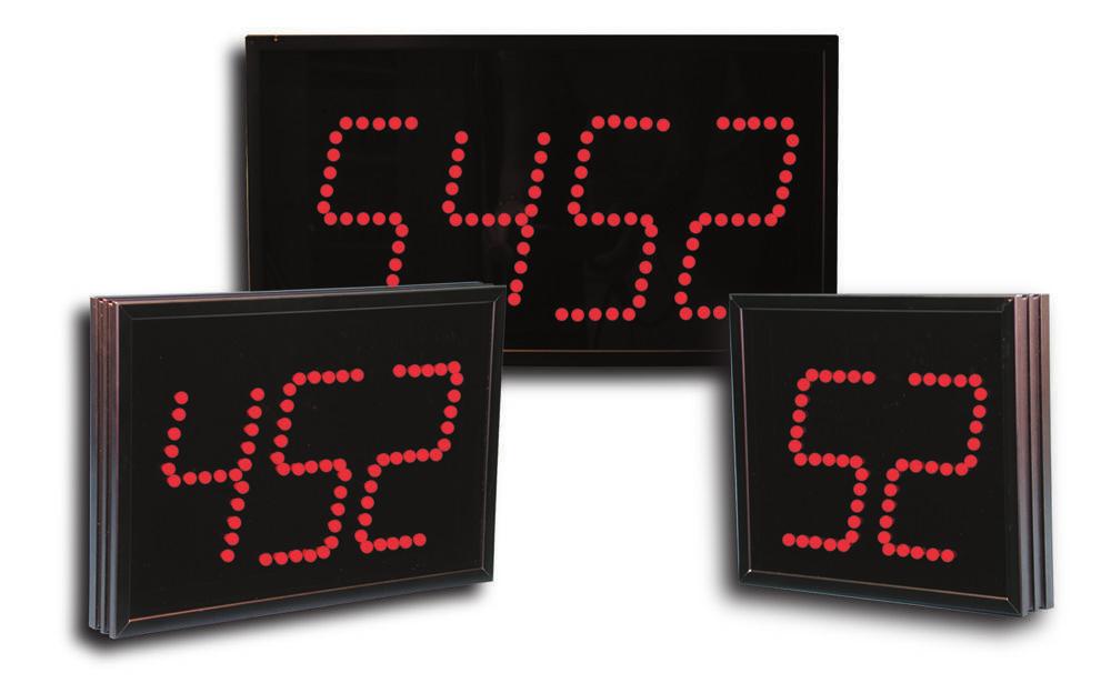
6 TX TX RX 24V 9.1" (23.1 cm) Model 220 Remote Display P.O. Box 1700, Broken Arrow, OK SELECT MODE PROGRAMMING SWITCHES SEE INSTRUCTION MANUAL 9.8" 2-DIGIT (24.9 cm) 1.5" (3.8 cm) A0220\AX\9700.ai 6 Support and Sales Microframe Corporation P.O. Box 1700 Broken Arrow, OK 74013
 1.5\" (3.8 cm) 230\AX\9700B.ai Support and Sales 800-635-3811 Microframe Corporation www.microframecorp.com P.O.")
7 INPUT 2 COMMON INPUT 1 24V 9.1" (23.1 cm) Model 230 Display MICROFRAME C O R P O R A T I O N SELECT MODE PROGRAMMING SWITCHES SEE INSTRUCTION MANUAL 13.2" 3-DIGIT (33.5 cm) 1.5" (3.8 cm) 230\AX\9700B.ai Support and Sales Microframe Corporation P.O. Box 1700 Broken Arrow, OK
 (3.8 cm) 240\AX\9700B.ai 8 Support and Sales 800-635-3811 Microframe Corporation www.microframecorp.com P.O.")
8 INPUT 2 COMMON INPUT 1 24V 9.1" (23.1 cm) Model 240 Display MICROFRAME C O R P O R A T I O N SELECT MODE PROGRAMMING SWITCHES SEE INSTRUCTION MANUAL 16.8" 4-DIGIT 1.5" (42.7 cm) (3.8 cm) 240\AX\9700B.ai 8 Support and Sales Microframe Corporation P.O. Box 1700 Broken Arrow, OK 74013
 INPUT 2 COMMON INPUT 1 24V Model 230 Display MICROFRAME C O R P O R A T I O N SELECT MODE PROGRAMMING SWITCHES SEE INSTRUCTION MANUAL 260\AX\9700D.")
9 9.1" (23.1 cm) 7.25 (18.4cm) 30" 6 DIGIT ( 76.2 cm ) 1.5" (3.8 cm) INPUT 2 COMMON INPUT 1 24V Model 230 Display MICROFRAME C O R P O R A T I O N SELECT MODE PROGRAMMING SWITCHES SEE INSTRUCTION MANUAL 260\AX\9700D.ai Support and Sales Microframe Corporation P.O. Box 1700 Broken Arrow, OK
 @1 Amp TO COMPUTER 265\AX\9700B.ai 10 Support and Sales 800-635-3811 Microframe Corporation www.microframecorp.com P.O. Box 1700 Broken Arrow, OK 74013")
10 24 V SELECT MA. B A T2 T R + - MODE A FUSE V 24 V 2.25" (5.7cm) 27" (68.6 cm) 30" (76.6 cm) 12" Amp TO COMPUTER 265\AX\9700B.ai 10 Support and Sales Microframe Corporation P.O. Box 1700 Broken Arrow, OK 74013
11 Powering the Display from 24V The Display ships with a 24V power adapter. Connect the wire ends to the board terminals labeled 24V. Note: The 20mA current loop input is a signal input and should not be confused with the 24V power input. Powering the Display from 110V The Display ships with a 110V cord installed. Simply plug the cord into an outlet. If the Display does not turn on, verify that the power selector switch is set to 110V. Powering the Display from 24V To set the Display to run off 24V, complete the following: (1) Disconnect the supplied 110V power cord; (2) Set the power switch to 24V; and (3) Connect the 24V source to the terminals labeled 24V. Microframe has 24V power adapter available as an option. Caution: Connecting 110V to the 24V input will damage the Display. Pressing the select button one time will cause the display to show all eights. Pressing the select button a second time will cause the display to go into a count mode. Pressing the select button a third time will cause the display to show the current software revison. The fourth button press will return the display to normal operation. This indoor Display can be wall mounted using the two keyhole cutouts in the back of the Display. Model 220 accepts RS232 as its only input signal. Models accept one of three input sources: RS232, RS485 or 20 ma current loop. A selector switch allows the user to change input settings. Connections should be as follows: RS232 Display Rx to Computer Tx Display Tx to Computer Rx Display Ground to Computer Ground RS485 A to A, B to B 20 ma Current loop See diagrams. Observe that the data input selector switch and baud rate are set appropriately. The Display power/processor light should flash when the Display is powered. 11
12 All serial data should be sent with: 8 Data bits, No parity bits, 1 or 2 stop bits. Seven data bits will work if odd or even parity is set. The Display will show as many numbers as it has digits preceding a carriage return. (CR) = Carriage Return or ASCII 13d or OD hex. Alpha characters mixed in with numbers will be ignored (SEE CHART 1 BELOW). The decimal point can be operated by simply placing the decimal in the number string where you want it to display (SEE CHART 1 BELOW). You may turn the colon "ON" by passing a colon (:). The colon will remain on for the current number only. (SEE CHART 1 BELOW). Pressing the select button one time will cause the display to show all eights. Pressing the select button a second time will cause the display to go into a count mode. Pressing the select button a third time will cause the display to show the current software revison. The fourth button press will return the display to normal operation. There are two protocols which can be used to control the display: Legacy mode and Standard CHART 1 ASCII mode. Legacy mode does not support all commands but it acts exactly like older Microframe displays. In this way, code written to drive our older displays will still work. New projects should be written around the "Standard ASCII" format. There are currently three supported commands in "Legacy Mode:" Display Address, Output Control, and Momentary Output. Commands are sent to the Display using a 4-byte data structure, which are defined below: Byte #1 On/Off OE = On Byte #2 (Command definition) 07 = Chime output 08 = Momentary Chime on 30(hex) = Display enable/disable Byte # (hex)= Display address Byte #4 03(hex) = Terminating character To enable Display address number 1, pass the following enable code: 0E (HEX) To disable Display address number 1, send the following code: 0F (HEX) Data Sent to Display Data Shown On Displays 12
13 To enable Display 2 and send "1234," then disable it, send the following hex values: 0E F To set the display address, see the programing instructions. This command can be used to control the optional "Triac" output. To turn the Triac output on send: 0E 07 XX 03 To turn off the output send: 0F 07 XX 03 X 'XX' is the Display address. To cause a momentary chime output in display 94, send the following: STX ETX STX ETX Pressing the Mode button one time will get you into the programming mode. The current mode is shown by the tens digit and the current MODE VALUE This command turns the Triac output on for approximately half a second and then turns off automatically. 0E 08 XX 03 'XX' is the Display address. STX = (ASCII start byte) A1 = Address byte 1(0-9 ASCII) A2 = Address byte 2(0-9 ASCII) C1 = Command Byte 1 (0-9 ASCII) C2 = Command Byte 2 (0-9 ASCII) D1 = Data byte 1 (0-9 ASCII) D2 = Data byte 2 (0-9 ASCII) ETX (ASCII end transmission) Commands Data 01 Display active/inactive 01/00 02 Mirror on/off 01/00 03 Chime on/off/momentary 01/00/02 04 Brightness auto/manual 01/00 05 Brightness value % Example: To enable display address 72, send it a number and disable it again and send the following: STX ETX CR STX ETX SELECT MODE PROGRAMMING SWITCHES 220\PX\9700 value is shown by the ones digit. Use the Mode button to advance through the mode settings. Use the Select button to change the value of a given mode. When the desired value is set, press the Mode button to advance to the next mode, or press and hold the Mode button to save changes and exit. Area1 *Value 0 no alpha characters Value 1 Accept alpha characters Area 2 Value 0 Baud Rate = 1200 Value 1 Baud Rate = 2400 Value 2 Baud Rate = 4800 *Value 3 Baud Rate = 9600 Value 4 Baud Rate = Value 5 Baud Rate = Value 6 Baud Rate =
14 Area 3 *Value 0 Auto Brightness Value 1 2% Brightness Value 2 3% " " Value 3 5% " " Value 4 8% " " Value 5 13% " " Value 6 22% " " Value 7 36% " " Value 8 60% " " Value 9 100% " " Area 4 *Value 0 Mirror Mode Off Value 1 Mirror Mode On Area 5** *Value 0 Zero Suppression/Expansion Off Value 1 Show one zero Value 2 Show two zeroes Value 3 Show three zeroes Value 4 Show four zeroes Value 5 Show five zeroes Value 6 Show six zeroes Area 6 *Value 0 Colons operate Together Value 1 Independent Colons Area 7 Value 0-9 = 10's digit of Address *Factory Default 0 Area 8 Value 0-9= 1's Digit of Address *Factory Default 1 Area 9 Value 0 Legacy Mode Protocol *Value 1 ASCII Protocol Value 2 General Scale Value 3 Specific Scale See Mode "A" Area A *Value 0 Mettler Toledo Value 1 Rice Lake * Factory Default **Modes Legacy and ASCII do simple zero suppression; specified zeroes are ignored. Please note that "Legacy mode" (Area 9 Mode 0) and "Standard ASCII" mode (Area 9 Mode 1) are full command structure protocols. These protocols are generally used in industrical applications where control over display addressing is neccessary. These modes can be used with scale indicators but care must be taken to avoid unintentionally sending data in command format. For information about the "Legacy mode" and "Standard ASCII" mode, please see the "Operation" section. Example: Definition: This is the most universal scale mode. In this mode the start byte does not matter. The Display will show the last six characters preceeding a Carrige Return or an "ETX." Alpha characters can be ignored based on the "ignore alpha" option. There are no addressing or special display commands in this mode. Negative signs will be placed where they are received in the string. This mode differs from standard mode by looking for the weight 6 bytes before the carriage return and for the negative sign designation in byte 1 of SWB. Microframe is commited to making the model 265 display work with as many different scale indicators as possible. To this end, Microframe has developed a General Scale Receive Logic mode which works with most scales. For those few scales which have been found not to work with the "General Scale" mode, we have written specific receive logic. If your indicator cannot be made to work with any of our existing logic, we will write logic specifically for your indicator. 14 This mode differs from General Scale Mode by looking for the negative sign in the fixed location "P" shown above. P = polarity, " " = +, "-" = -. NOTE: All serial data should be sent with: 8 Data bits No parity bits 1 or 2 stop bits.
15 INPUT 2 COMMON INPUT 1 24V Model 220 Remote Display P.O. Box 1700, Broken Arrow, OK SELECT MODE PROGRAMMING SWITCHES SEE INSTRUCTION MANUAL RS-232C CONNECTIONS FOR 9-PIN D-Sub Pin 2 - T X ( Transmit Data ) Pin 3 - RX ( Receive Data) Pin 5 - ( Signal Ground ) 115 TO 24 V WALL MOUNTED AMPS 2X0\PX\9706.AI 15
16 16
17 485 A 1 T2 232 T R SELECT MODE 232 PROGRAMMING SWITCHES SEE INSTRUCTION MANUAL 1A FUSE 20 MA. 115 V 24 V 24 V B + - A0265 DISPLAY 1A FUSE 1 Communication and power connections. 24 V MA. B T2 T R + - A 115 V Option Selection SELECT PROGRAMMING SWITCHES MODE 232 SEE INSTRUCTION MANUAL 24 V 24V RS 485 TX2 TX1 RX 20 MA. RS-232C CONNECTIONS FOR 9-PIN D-Sub 24V RS 485 TX2 TX1 RX 20 MA. RS-232C CONNECTIONS FOR 25-PIN D-Sub PIN T X ( Transmit Data ) 4 5 ( Signal Ground ) PIN T X ( Transmit Data ) ( Signal Ground ) X0\PX\9705.ai 25 Be sure to set your computer ComPort to [Flow Control=None]. This will allow you to communicate with the Display without a null modem. Otherwise, your computer will be looking for a "Clear to Send" from the Display which is not connected. 17
18 PROGRAMMING SWITCHES SIGNAL TRANSFORMER PROGRAMMING SWITCHES SIGNAL TRANSFORMER Model A Digit Display PIN 7 PIN 8 PIN 6 PIN 5 24V 1 AMP RS 485 B A TX2 RS 232 TX1 RX 20 MA. + - LP V PIN 3 PIN 4 PIN 2 PIN 1 SELECT MODE 232 SEE INSTRUCTION MANUAL REAR VIEW Model A Digit Display B A T2 232 T R 20MA + - PIN 7 PIN 8 PIN 6 PIN 5 24V 1 AMP RS 485 B A TX2 RS 232 TX1 RX 20 MA. + - LP V PIN 3 PIN 4 PIN 2 PIN 1 SELECT MODE SEE INSTRUCTION MANUAL 232 REAR VIEW B A T2 232 T R 20MA X0\AX\9704.ai
19 SIGNAL TRANSFORMER Model A Digit Display PIN 7 PIN 8 PIN 6 PIN 5 1 AMP 24V RS 485 B A RS 232 TX2 TX1 RX 20 MA. + - LP SELECT MODE 232 PROGRAMMING SWITCHES SEE INSTRUCTION MANUAL 24 V PIN 3 PIN 4 PIN 2 PIN 1 TIVE RECEIVER DISPLAY 20MA CURRENT SOURCE ON > > NON ISOLATED TIVE RECEIVER B A T2 232 T R 20MA + - _ + CUSTOMER PASSIVE TRANSMITTER PASSIVE RECEIVER DISPLAY > > ISOLATED PASSIVE RECEIVER 20MA CURRENT SOURCE OFF B A T2 232 T R 20MA CUSTOMER TIVE TRANSMITTER + 20MA CURRENT SOURCE 2X0\PX\9702.ai 19
20 B A RS 232 RX PROGRAMMING SWITCHES PIN 7 PIN 8 PIN 6 PIN 5 SIGNAL TRANSFORMER PIN 3 PIN 4 PIN 2 PIN 1 24V RS AMP TX2 TX1 20 MA. + - LP SELECT MODE SEE INSTRUCTION MANUAL 24 V Model A Digit Display PASSIVE RECEIVER DISPLAY > > 20MA CURRENT SOURCE OFF MULTIPLE DISPLAY PASSIVE TRANSMITTER NOTE: Only 1 active receiver display per circuit B A TIVE RECEIVER DISPLAY 20MA CURRENT SOURCE ON > > T2 232 T R 20MA + - _ CUSTOMER PASSIVE TRANSMITTER + _ B A T2 232 T R 20MA + - N.C. _ PASSIVE RECEIVER DISPLAY > > MULTIPLE DISPLAY TIVE TRANSMITTER 20MA CURRENT SOURCE OFF B A PASSIVE RECEIVER DISPLAY > > T2 232 T R 20MA _ CUSTOMER TIVE TRANSMITTER 20MA CURRENT SOURCE OFF + 20MA CURRENT SOURCE B A T2 232 T R 20MA _ 2X0\AX\9703.ai 20
21 SYMPTOM POSSIBLE CAUSE CURE No data on Remote Display and No Processor LED. Processor LED blinks slow and never blinks fast and no data on Displays. Processor LED blinks fast when transmitted to, but numbers don t display. Remote Display shows 888 all the time. First Remote Display works but second Remote Display does not work. The system works until connected to a second or third Display, then one or all units stop working. No power to Remote Display. Power not connected to proper input terminal or volt or power switch not in proper position. Remote Display is dead. No data being received or receive circuit in Remote Display is dead. Data protocol switch not in proper position or data leads connected to wrong terminals. Wrong data being received or wrong baud rate. Processor blinks even if wrong baud rate so you know there is a connection. Self-Test Mode. Check wiring between Displays. Check to see if Processor LED is blinking as above on second Display. Output from first Remote Display is dead or input to send Remote Display is dead. The RS232 port is loaded by having more than one device connected to the single output of the computer at one time. Check power source. If 24 V connected to 24V terminals then set power switch to 24 volt position. If 110 V connected to 110V terminals, then set power switch to 110 volt position. CAUTION: Do Not CONNECT 110V to 24Volt terminal. Damage will occur to your Display. Remove back panel and measure voltage from fuse to ground. It should be volts both sides. If fuse is blown, replace with 1 1/2 Amp 3AG fuse. If no voltage, then check supply voltage to Display. If voltage is present and fuse is okay, then set option 1 to test for all 8s. If this doesn t work, return to factory. Processor blinking power light will change blink rate to fast blink each time data is received even if different baud rate. If blink rate remains unchanged then no data is being received. Check connections and transmitter. Set switch to match Display to data type. Set to 232 for RS232, 20 for 20 ma current loop and set to 485 for RS485. Connect proper signal to matching terminal. Verify correct Baud Rate. Check the data stream to see if it contains numbers and a carriage return. Toggle the power or press the select button to get to count mode, then again to show the rev, and finally again to return to normal mode. Troubleshoot as above to determine if signal is arriving at the second Display. It could be the first Remote Display output or the second Remote Display input is not working. It may be necessary to swap the two Remote Displays to determine the problem. Return to factory for repair. Connect output of first Display to input of second Display. Connect output of second Display to input of third Display and so on. Do not connect all Displays directly to one computer because this will load the output of the computer. 21
22
Noise Detector ND-1 Operating Manual
 Noise Detector ND-1 Operating Manual SPECTRADYNAMICS, INC 1849 Cherry St. Unit 2 Louisville, CO 80027 Phone: (303) 665-1852 Fax: (303) 604-6088 Table of Contents ND-1 Description...... 3 Safety and Preparation
AES-402 Automatic Digital Audio Switcher/DA/Digital to Analog Converter
 Broadcast Devices, Inc. AES-402 Automatic Digital Audio Switcher/DA/Digital to Analog Converter Technical Reference Manual Broadcast Devices, Inc. Tel. (914) 737-5032 Fax. (914) 736-6916 World Wide Web:
4X1 Gefen TV Switcher GTV-HDMI N. User Manual
 4X1 Gefen TV Switcher GTV-HDMI1.3-441N User Manual INTRODUCTION Congratulations on your purchase of the 4x1 GefenTV Switcher. Your complete satisfaction is very important to us. GefenTV GefenTV is a unique
AES-404 Digital Audio Switcher/DA/Digital to Analog Converter
 Broadcast Devices, Inc. AES-404 Digital Audio Switcher/DA/Digital to Analog Converter Technical Reference Manual Broadcast Devices, Inc. Tel. (914) 737-5032 Fax. (914) 736-6916 World Wide Web: www.broadcast-devices.com
MENU EXECUTE Shiloh Road Alpharetta, Georgia (770) FAX (770) Toll Free
 FAX (770) Toll Free") Instruction Manual Model 2584-31 Combiner May 2011, Rev. A RF MONITOR GAIN = -15 MENU MODEL 2584 COMBINER CROSS TECHNOLOGIES INC. ALARM REMOTE POWER EXECUTE Data, drawings, and other material contained
Instruction Manual Model 2584-31 Combiner May 2011, Rev. A RF MONITOR GAIN = -15 MENU MODEL 2584 COMBINER CROSS TECHNOLOGIES INC. ALARM REMOTE POWER EXECUTE Data, drawings, and other material contained
Mounting Dimensions / Viewing 2 Mounting Options 3. Wiring Configuration 4. Quick Set up Procedure 5. Changing Intensity 6.
 Contents Section Mounting Dimensions / Viewing 2 Mounting Options 3 Section 2 Wiring Configuration 4 Section 3 Quick Set up Procedure 5 Section 4 Changing Intensity 6 Section 5 Option Summary 7 Section
MONITOR POWER Shiloh Road Alpharetta, Georgia (770) FAX (770) Toll Free
 FAX (770) Toll Free") Instruction Manual Model 2099-10xx 10MHz Frequency Source April 2014, Rev. H MENU INTERNAL LEVEL = +10dBm MONITOR POWER 1 2 MODEL 2099 FREQUENCY SOURCE CROSS TECHNOLOGIES INC. ALARM OVEN REMOTE EXECUTE
Instruction Manual Model 2099-10xx 10MHz Frequency Source April 2014, Rev. H MENU INTERNAL LEVEL = +10dBm MONITOR POWER 1 2 MODEL 2099 FREQUENCY SOURCE CROSS TECHNOLOGIES INC. ALARM OVEN REMOTE EXECUTE
OWNERS MANUAL. Revision /01/ Lightronics Inc. 509 Central Drive Virginia Beach, VA Tel
 OWNERS MANUAL Revision 1.8 09/01/2002 OWNERS MANUAL Page 2 of 12 AR-1202 UNIT DESCRIPTION The AR-1202 consists of a processor and 12 dimmer channels of 2.4KW each. Each dimmer channel is protected by a
Operator s Manual. Ultegra. Health Scale. Fairbanks Scales by Fairbanks Scales Inc. All rights reserved. Revision 5 06/07
 Operator s Manual Ultegra Health Scale Fairbanks Scales 2007 by Fairbanks Scales Inc. All rights reserved 50735 Revision 5 06/07 Amendment Record Ultegra Health Scale 50735 Manufactured by Fairbanks Scales
DVI Video Switcher. 4 to 1 DVI Switcher with Remote/RS-232 control 8 to 1 DVI Switcher with Remote/RS-232 control VS410DVIR VS810DVIR
 DVI Video Switcher 4 to 1 DVI Switcher with Remote/RS-232 control 8 to 1 DVI Switcher with Remote/RS-232 control VS410DVIR VS810DVIR Instruction Manual VS410DVIR VS810DVIR Actual products may vary from
SR - 516D DESK TOP DMX REMOTE STATION. Version: Date: 05/16/2013
 SR - 516D DESK TOP DMX REMOTE STATION Version: 1.10 Date: 05/16/2013 Page 2 of 10 TABLE OF CONTENTS DESCRIPTION 3 POWER REQUIREMENTS 3 INSTALLATION 3 CONNECTIONS 3 POWER CONNECTIONS 3 DMX CONNECTIONS 3
NS-3 RF Noise Source Operation Manual
 RF Noise Source Operation Manual Version 2.04 June 3, 2016 SPECIFICATIONS Frequency... Maximum output level... Output flatness... (at max output level) Impedance... Displayed level... Repeatability...
AS-300D Series Smart Bench Scales Owner s Manual
 DETE CTO A Division of Cardinal Scale Manufacturing Co. AS-300D Series Smart Bench Scales Owner s Manual 8527-M214-O1 Rev B 01/03 PO BOX 151 WEBB CITY, MO 64870 417-673-4631 Printed in USA INTRODUCTION
Configuration Vestas VMP3500
 Configuration Vestas VMP3500 1. Table of contents 1. Table of contents... 2 2. Introduction... 3 3. Vestas turbines (RCS)... 4 3.1. VMP 3500 controller... 4 3.2. Communication with the CT3230 current loop
INSTALLATION MANUAL FT-FOTR-1VDE-ST-S
 INSTALLATION MANUAL FT-FOTR-1VDE-ST-S 1-Channel Digital Duplex Baseband Video Transmitter and Receiver With Reverse Data Transmission & Ethernet Transmission v1.0 4/5/11 1 PACKAGE CONTENTS This package
Master Time Clock MTC Users Manual
 Master Time Clock MTC-6000 Users Manual Midwest Time Control Phone (972)987-4408 Toll Free (888)713-0373 FAX (877)720-9291 www.midwest-time.com sales@midwest-time.com TABLE OF CONTENTS TOPIC PAGE GENERAL
RD RACK MOUNT DIMMER OWNERS MANUAL VERSION /09/2011
 RD - 122 RACK MOUNT DIMMER OWNERS MANUAL VERSION 1.3 03/09/2011 Page 2 of 14 TABLE OF CONTENTS UNIT DESCRIPTION AND FUNCTIONS 3 POWER REQUIREMENTS 3 INSTALLATION 3 PLACEMENT 3 POWER CONNECTIONS 3 OUTPUT
Operation/Reference Guide IRIS. Infrared/Serial Data Capture Unit. Control System Accessories
 Operation/Reference Guide IRIS Infrared/Serial Data Capture Unit Control System Accessories Last Revised: 1/17/2007 AMX Limited Warranty and Disclaimer All products returned to AMX require a Return Material
10MHz Source/Inserter
 Instruction Manual Model 2099-218 10MHz Source/Inserter Redundant 18V January 2011, Rev. A RX 0.32 A TX 0.86 A REF ON REF OFF MENU MODEL 2099 SOURCE/INSERTER CROSS TECHNOLOGIES INC. PS1 PS2 REMOTE ALARM
Model VS-2A 2-Port VGA Switch with Audio & Serial Control
 Model VS-2A 2-Port VGA Switch with Audio & Serial Control UMA1119 Rev B Copyright Hall Research, Inc. All rights reserved. 1163 Warner Ave Tustin, CA 92780, Ph: (714)641-6607, Fax -6698 Model VS-2A 2 2-Port
MENU EXECUTE Shiloh Road Alpharetta, Georgia (770) FAX (770) Toll Free
 FAX (770) Toll Free") Instruction Manual Model 2016-1250 Downconverter May 2009 Rev A F=2501.750 G=+25.0 MENU MODEL 2016 DOWNCONVERTER CROSS TECHNOLOGIES INC. ALARM REMOTE POWER EXECUTE Data, drawings, and other material contained
Instruction Manual Model 2016-1250 Downconverter May 2009 Rev A F=2501.750 G=+25.0 MENU MODEL 2016 DOWNCONVERTER CROSS TECHNOLOGIES INC. ALARM REMOTE POWER EXECUTE Data, drawings, and other material contained
AES Channel Digital/Analog Audio Switcher/DA/Digital to Analog Converter
 Broadcast Devices, Inc. AES-408 8 Channel Digital/Analog Audio Switcher/DA/Digital to Analog Converter Technical Reference Manual Broadcast Devices, Inc. Tel. (914) 737-5032 Fax. (914) 736-6916 World Wide
Foreword: The purpose of this document is to describe how to install and configure Neets 4 relay box
 Foreword: The purpose of this document is to describe how to install and configure Neets 4 relay box COPYRIGHT All information contained in this manual is the intellectual property of and copyrighted material
USER MANUAL. DV-HSW-41 HDMI 4x1 SWITCHER LIT Bergen Boulevard, Woodland Park, NJ Tel FAX Web
 USER MANUAL DV-HSW-41 HDMI 4x1 SWITCHER 244 Bergen Boulevard, Woodland Park, NJ 07424 Tel 973-785-4347 FAX 973-785-3318 Web www.fsrinc.com LIT1372 PROPRIETARY INFORMATION All information in this manual
Model 974A Quad Counter/Timer Operating Manual
 ORTEC Model 974A Quad Counter/Timer Operating Manual Printed in U.S.A. ORTEC Part No. 932501 0210 Manual Revision A Advanced Measurement Technology, Inc. a/k/a/ ORTEC, a subsidiary of AMETEK, Inc. WARRANTY
Extra long-range RFID (proximity) card reader
 card reader") GP90A Extra long-range RFID (proximity) card reader (1) Features: Extra long reading range of up to 90 cm with ISO-size passive RFID cards*, over 100 cm with special optimized passive cards High-precision
GP90A Extra long-range RFID (proximity) card reader (1) Features: Extra long reading range of up to 90 cm with ISO-size passive RFID cards*, over 100 cm with special optimized passive cards High-precision
User Manual DV-HDSS-41-TX. 4x1 4K Scaling Presentation Switcher with Dual Outputs. NOTE: See FSR LIT1628 API manual for serial commands.
 User Manual DV-HDSS-41-TX 4x1 4K Scaling Presentation Switcher with Dual Outputs NOTE: See FSR LIT1628 API manual for serial commands. 43153 LIT1627 Important Safety Instructions. Table of Contents Important
MS2540 Current Loop Receiver with RS485 Communication
 MS2540 Current Loop Receiver with RS485 Communication User Manual Metal Samples Company A Division of Alabama Specialty Products, Inc. 152 Metal Samples Rd., Munford, AL 36268 Phone: (256) 358 4202 Fax:
Operating Manual. 50mW C-Band EDFA with GPIB and RS232 Interface
 Fibotec Fiberoptics GmbH Herpfer Str. 40 98617 Meiningen Germany Tel. +49 3693 8813-200 Fax. +49 3693 8813-201 www.fibotec.com Operating Manual 50mW C-Band EDFA with GPIB and RS232 Interface (Version 1.1
ES-450J2 Universal 2 Channel Jog/Shuttle Remote
 ES-450J2 Universal 2 Channel Jog/Shuttle Remote Users Manual ES-450, ES-450J and ES-450J2 are trademarks of JLCooper Electronics. All other brand names are the property of their respective owners. ES-450J2
USER INSTRUCTIONS MODEL CSI-200 COAXIAL SYSTEM INTERFACE
 USER INSTRUCTIONS MODEL CSI-200 COAXIAL SYSTEM INTERFACE 9350-7676-000 Rev B, 5/2001 PROPRIETARY NOTICE The RTS product information and design disclosed herein were originated by and are the property of
BRIGHTLINK HDMI EXTENDER OVER ETHERNET - H METER MODEL: BL-EXT-IP-264
 BRIGHTLINK HDMI EXTENDER OVER ETHERNET - H.264-120 METER MODEL: BL-EXT-IP-264 Operating Instructions BRIGHTLINKAV.COM 1 Introduction This HDMI over IP Extender use the advanced H.264 as the compression
CS x1 RS-232 Computer Controlled Video Switcher. Instruction Manual
 CS-1600 16x1 RS-232 Computer Controlled Video Switcher Instruction Manual Thank you for purchasing one of our products. Please read this manual before using this product. When using this product, always
ST60-DVC VTR CONTROLLER ST60-AG57 VTR CONTROLLER
 12843 Foothill Blvd. Suite C Sylmar, California 91342 V: 818.898.3380 F: 818.898.3360 sales@dnfcontrols.com ST60-DVC VTR CONTROLLER ST60-AG57 VTR CONTROLLER USER MANUAL Manual Version.... 2.1 122203 Document
HDMI Extender Transmission more than 3800M
 HDMI Extender Transmission more than 3800M Operating Instructions Dear Customer Thank you for purchasing this product. For optimum performance and safety, please read these instructions carefully before
BRIGHTLINK HD Video Wall Controller BRIGHTLINKAV.COM
 BRIGHTLINK HD Video Wall Controller MODEL: BL-VW22 Operating Instructions BRIGHTLINKAV.COM Dear Customer Thank you for purchasing this product. For optimum performance and safety, please read these instructions
MASTR II BASE STATION 12/24V POWER SUPPLY 19A149979P1-120 VOLT/60 Hz 19A149979P2-230 VOLT/50 Hz
 Mobile Communications MASTR II BASE STATION 12/24V POWER SUPPLY 19A149979P1-120 VOLT/60 Hz 19A149979P2-230 VOLT/50 Hz CAUTION THESE SERVICING INSTRUCTIONS ARE FOR USE BY QUALI- FIED PERSONNEL ONLY. TO
CrossLine Generator Operation Manual
 WARRANTY MicroImage Video Systems warrants that each CL5400A is free from defects due to faulty materials or improper workmanship for a period of one (1) year. MicroImage Video Systems further warrants
INSTRUCTION MANUAL. 19 HD Widescreen Water Resistant Television VSPA19LCD-AE1B VSPA19LCD-AE1M VSPA19LCD-AE1W. Model No. FINGER TOUCH TECHNOLOGY RATED
 INSTRUCTION MANUAL 19 HD Widescreen Water Resistant Television VSPA19LCD-AE1B Model No. VSPA19LCD-AE1M VSPA19LCD-AE1W FINGER TOUCH TECHNOLOGY IMPORTANT: Please read these instructions before installing
TRANSCENSION 6-CHANNEL DMX DIMMER PACK (order code: BOTE40) USER MANUAL
 USER MANUAL") www.prolight.co.uk TRANSCENSION 6-CHANNEL PACK (order code: BOTE40) USER MANUAL SAFETY WARNING FOR YOUR OWN SAFETY, PLEASE READ THIS USER MANUAL CAREFULLY BEFORE YOUR INITIAL START-UP! CAUTION! Keep this
www.prolight.co.uk TRANSCENSION 6-CHANNEL PACK (order code: BOTE40) USER MANUAL SAFETY WARNING FOR YOUR OWN SAFETY, PLEASE READ THIS USER MANUAL CAREFULLY BEFORE YOUR INITIAL START-UP! CAUTION! Keep this
Sprite TL Quick Start Guide
 Sprite TL Quick Start Guide with 115 VAC Power Cord and 4-Conductor Signal Cable Reference Manual Sprite TL Online and downloadable Product Manuals and Quick Start Guides are available at www.hydrosystemsco.com
HD Digital Set-Top Box Quick Start Guide
 HD Digital Set-Top Box Quick Start Guide Eagle Communications HD Digital Set-Top Box Important Safety Instructions WARNING TO REDUCE THE RISK OF FIRE OR ELECTRIC SHOCK, DO NOT EXPOSE THIS PRODUCT TO RAIN
Evolution Digital HD Set-Top Box Important Safety Instructions
 Evolution Digital HD Set-Top Box Important Safety Instructions 1. Read these instructions. 2. Keep these instructions. 3. Heed all warnings. 4. Follow all instructions. 5. Do not use this apparatus near
Model: UHD41-ARC. Installation Guide
 Model: UHD41-ARC Installation Guide 1 Safety Information: Electrical safety Use only the power supplies and the AC power cord that were included with your product. Use of other power supplies could damage
Owner's Manual LIGHTING CONTROL CONSOLE TEATRONICS LIGHTING CONTROLS, INC. PROCON II Los Osos Valley Rd., Ste. G Los Osos, CA 93402
 Owner's Manual PROCON II LIGHTING CONTROL CONSOLE TEATRONICS LIGHTING CONTROLS, INC. 1236 Los Osos Valley Rd., Ste. G Los Osos, CA 93402 Phone: (805) 528-6900 PROCON II FAX: (805) 528-9345 12/01/94 Page//
SM DMX LIGHTING CONTROLLER OWNERS MANUAL. May 19, 2009
 SM - 192 DMX LIGHTING CONTROLLER OWNERS MANUAL May 19, 2009 INSTRUCTION MANUAL Page 2 of 8 MAIN FEATURES 192 DMX Channels 30 Scene Banks of 8 programmable scenes each 6 Programmable chases with up to 240
User Manual. HDBaseT Wallplate Transmitter over Cat6/6A. Front View Panduit Dr, Tinley Park, IL (708)
") User Manual HDBaseT Wallplate Transmitter over Cat6/6A Front View 18900 Panduit Dr, Tinley Park, IL 60487 (708) 532-1800 Back View TABLE OF CONTENTS Introduction 2 Features 3 Package Contents 3 Technical
User Manual HDBaseT Wallplate Transmitter over Cat6/6A Front View 18900 Panduit Dr, Tinley Park, IL 60487 (708) 532-1800 Back View TABLE OF CONTENTS Introduction 2 Features 3 Package Contents 3 Technical
Kramer Electronics, Ltd. USER MANUAL. Model: VS x 1 Sequential Video Audio Switcher
 Kramer Electronics, Ltd. USER MANUAL Model: VS-120 20 x 1 Sequential Video Audio Switcher Contents Contents 1 Introduction 1 2 Getting Started 1 2.1 Quick Start 2 3 Overview 3 4 Installing the VS-120 in
Model 1476-C SuperQuad HR
 Model 1476-C SuperQuad HR Installation and Operating Instructions Table of Contents Page Table of Content... 2 System Description... 3 Features... 3 Installation... 4 Internal Setups... 4 Connections...
2002 Martin Professional A/S, Denmark.
 Freekie user manual 2002 Martin Professional A/S, Denmark. All rights reserved. No part of this manual may be reproduced, in any form or by any means, without permission in writing from Martin Professional
RS232 settings are internally definable via jumper blocks, to accommodate interfacing with a wide range of control products.
 Appendix C RS232 Protocol RS232 settings are internally definable via jumper blocks, to accommodate interfacing with a wide range of control products. Baud rate 96ØØ or 192ØØ Echo status AUTO or REQUEST
O P E R A T I O N M A N U A L. RF-Reader. Stand-alone-Reader Leser 2plus with RS-232 interface
 O P E R A T I O N M A N U A L Version 01/05 RF-Reader Stand-alone-Reader Leser 2plus with RS-232 interface Important! Read by all means! To maintain the perfect shipping conditions and to ensure safe operation
APSPB PUSH BUTTON ZERO Installation Manual
 APSPB PUSH BUTTON ZERO Installation Manual CARDINAL SCALE MFG. CO. 8527-0579-0M Rev A 203 E. Daugherty, Webb City, MO 64870 USA Printed in USA 12/14 Ph: 417-673-4631 Fax: 417-673-2153 www.detectoscale.com
Safety Information. Camera System. If you back up while looking only at the monitor, you may cause damage or injury. Always back up slowly.
 Table of Contents Introduction...3 Safety Information...4-6 Before Beginning Installation...7 Installation Guide...8 Wiring Camera & Monitor...9-10 Replacement Installation Diagram...11 Clip-On Installation
INSTALLATION MANUAL FT-FOTR-8VD-ST-S. 8-Channel Digital Duplex Baseband Video Transmitter and Receiver With Reverse Data Transmission for PTZ Cameras
 INSTALLATION MANUAL FT-FOTR-8VD-ST-S 8-Channel Digital Duplex Baseband Transmitter and Receiver With Reverse Transmission for PTZ Cameras v1.0 4/5/11 1 PACKAGE CONTENTS This package contains: One each
CAUTION RISK OF ELECTRIC SHOCK NO NOT OPEN
 Evolution Digital HD Set-Top Box Important Safety Instructions 1. Read these instructions. 2. Keep these instructions. 3. Heed all warnings. 4. Follow all instructions. 5. Do not use this apparatus near
HDS-42AVR HDMI Switcher INSTALLATION MANUAL
 HDS-42AVR HDMI Switcher INSTALLATION MANUAL -42AVR-Manual.indd 1 Table Of Contents Introduction...3 Safety Information...4 Kit Contents...4 Feature Set...4 HDS-42AVR Remote Control/Operation...5 Specifications...6
USER S MANUAL. Deuce HD User's Manual WORLD HEADQUARTERS
 USER S MANUAL WORLD HEADQUARTERS Artel Video Systems 5B Lyberty Way Westford, MA 01886 Tel: (978) 263-5775 Fax: (978) 263-9755 Email: info@artel.com Web: www.artel.com P/N 1219 Rev. F Copyright 2016 USER
Applied Measurements Ltd
 Applied Measurements Ltd 3 Mercury House, Calleva Park Aldermaston, Berkshire RG7 8PN Telephone: +44 (0) 118 981 7339 Fax: +44 (0) 118 981 9121 E-mail: info@appmeas.co.uk http://www.appmeas.co.uk Serial
1080P. 3GSDI Audio De-Embedder. GEF-SDI-AUDD User Manual.
 1080P 3GSDI Audio De-Embedder GEF-SDI-AUDD User Manual www.gefenpro.com ASKING FOR ASSISTANCE Technical Support: Telephone (818) 772-9100 (800) 545-6900 Fax (818) 772-9120 Technical Support Hours: 8:00
OWNERS MANUAL. Revision /29/ Lightronics Inc. 509 Central Drive Virginia Beach, VA Tel
 OWNERS MANUAL Revision 1.87 01/29/2006 Page 2 of 17 TABLE OF CONTENTS AR-1202 UNIT DESCRIPTION 3 EXTERNAL CONTROLS 3 POWER REQUIREMENTS 3 INSTALLATION 3 Physical Location 3 Power Input Connections 3 Three
ARS x4 MATRIX SWITCHER Instruction Manual
 ARS-8400 8x4 MATRIX SWITCHER Instruction Manual Thank you for purchasing one of our products. Please read this manual before using this product. When using this product, always follow the instructions
LDG ALK-2 Two-Port Audio/Linear/Key Switch
 ALK-2 OPERATIONS MANUAL MANUAL REV A LDG ALK-2 Two-Port Audio/Linear/Key Switch LDG Electronics 1445 Parran Road St. Leonard MD 20685-2903 USA Phone: 410-586-2177 Fax: 410-586-8475 ldg@ldgelectronics.com
USER MANUAL FOR THE ANALOGIC GAUGE FIRMWARE VERSION 1.0
 by USER MANUAL FOR THE ANALOGIC GAUGE FIRMWARE VERSION 1.0 www.aeroforcetech.com Made in the USA! WARNING Vehicle operator should focus primary attention to the road while using the Interceptor. The information
Commander 384. w w w. p r o l i g h t. c o. u k U S E R M A N U A L
 Commander 384 w w w. p r o l i g h t. c o. u k U S E R M A N U A L 1, Before you begin 1.1: Safety warnings...2 3 1.2: What is included...4 1.3: Unpacking instructions...4 2, Introduction 2.1: Features...4
Kramer Electronics, Ltd. USER MANUAL. Model: VS-88HD. 8x8 SD/HD-SDI Matrix Switcher
 Kramer Electronics, Ltd. USER MANUAL Model: VS-88HD 8x8 SD/HD-SDI Matrix Switcher Contents Contents 1 Introduction 1 2 Getting Started 1 2.1 Quick Start 1 3 Overview 3 4 Your VS-88HD 8x8 SD/HD-SDI Matrix
Model No. ST60-S (-SRN, -SRK, -DRN, -DRK)
") 12843 Foothill Blvd., Suite D Sylmar, CA 91342 818 898 3380 voice 818 898 3360 fax www.dnfcontrols.com Model No. ST60-S (-SRN, -SRK, -DRN, -DRK) VTR CONTROLLER Sony Protocol USER MANUAL Manual Version.........
12843 Foothill Blvd., Suite D Sylmar, CA 91342 818 898 3380 voice 818 898 3360 fax www.dnfcontrols.com Model No. ST60-S (-SRN, -SRK, -DRN, -DRK) VTR CONTROLLER Sony Protocol USER MANUAL Manual Version.........
ST-CCTV-VBAC 1 Channel UTP Active Video Balun Transceiver
 INSTALLATION MANUAL ST-CCTV-VBAC 1 Channel UTP Active Video Balun Transceiver Copyright North American Cable Equipment, Inc. 1 PACKAGE CONTENTS This package contains: One ST-CCTV-VBAC-TX Active Video Transmitter
CC2000 SERIES SYSTEM CLOCKS / DISPLAYS
 FN:CC2KMAN1.DOC CC2000 SERIES SYSTEM CLOCKS / DISPLAYS DESCRIPTION CC2000 Series System Clocks provide an economical solution for any size clock system. They are easily corrected by master clock systems
SCALE & WEIGHT DISPLAYS
 The MICRO SERIES SCALE & WEIGHT DISPLAYS LARGE DIGIT MODELS Mighty-5S DPM MODELS Micro-S & Mighty-1S Mighty-1S Micro-S ELECTRO-NUMERICS, INC. Introduction The Electro-Numerics family of Digital Panel Meters
Table of contents. Opening the Overhead Monitor... 4 Precautions Care And Maintenance... 5 Operating OHM102/153 Monitor...
 Warning! The Clarion OHM102/OHM153 overhead monitor systems are designed for strictly for rear seat entertainment. Viewing the monitor while operating a motor vehicle can result in serious injury and/or
INSTRUCTION MANUAL MODEL 2710 SUBCARRIER DEMODULATOR
 INSTRUCTION MANUAL MODEL 2710 SUBCARRIER DEMODULATOR Data, drawings, and other material contained herein are proprietary to Cross Technologies, Inc., and may not be reproduced or duplicated in any form
USER MANUAL. Kramer Electronics, Ltd. Models:
 Kramer Electronics, Ltd. USER MANUAL Models: VP-88ETH, 8x8 RGBHV / Balanced Audio Matrix Switcher VP-84ETH, 8x4 RGBHV / Balanced Audio Matrix Switcher VP-82ETH, 8x2 RGBHV / Balanced Audio Matrix Switcher
USER MANUAL FOR THE ANALOGIC GAUGE FIRMWARE VERSION 1.1
 by USER MANUAL FOR THE ANALOGIC GAUGE FIRMWARE VERSION 1.1 www.aeroforcetech.com Made in the USA! WARNING Vehicle operator should focus primary attention to the road while using the Interceptor. The information
Wind Indicator LED. Contents. Instruction for Use xx.x00, x08, xx.10
 Wind Indicator LED Instruction for Use 4.3225.xx.x00, 4.3225.10.x08, 4.3225.xx.10 Contents 1. General Information 2 1.1 Versions of the Indicator 2 1.2 Elements of the Indicator 3 2. Installation 4 2.1
H.264 HDMI Extender over IP Extender With LED, Remote, POE, RS232 WolfPack Operating Instruction
 H.264 HDMI Extender over IP Extender With LED, Remote, POE, RS232 WolfPack Operating Instruction 1 Introduction This WolfPack HDMI over IP Extender use the advanced H.264 as the compression type, which
DUAL/QUAD DISPLAY CONTROLLER Operation Manual
 DUAL/QUAD DISPLAY CONTROLLER Operation Manual Model PXD524 MicroImage Video Systems division of World Video Sales Co., Inc PO Box 331 Boyertown, PA 19512 Phone 610-754-6800 Fax 610-754-9766 sales@mivs.com
User Manual. Model 1372A and 1374A HDMI Switchers. 1T-SX-632 Model 1372A 2X1 Switcher. v1.3 2x1 SWITCHER. v1.3 INPUT ENHANCE POWER
 User Manual 1T-SX-632 Model 1372A 2X1 Switcher v1.3 v1.3 2x1 SWITCHER 1 2 INPUT ENHANCE POWER 1 2 INPUT ENHANCE POWER Model 1372A and 1374A HDMI Switchers Table Of Contents 1.0 Introduction.......................
5.1 + Stereo Monitor Controller
 Broadcast Devices, Inc. Technical Reference Manual 5.1 + Stereo Monitor Controller Broadcast Devices, Inc. 2066 E. Main Street Cortlandt Manor, NY 10567 Tel. (914) 737-5032 Fax. (914) 736-6916 World Wide
HomeVision-PC Owner s Manual Version 2.62
 HomeVision-PC Owner s Manual Version 2.62 Custom Solutions, Inc. No part of this document may be reproduced or transmitted in any form or by any means, electronic or mechanical, for any purpose, without
Master Time Clock MTC-200 MTC-400 MTC-600. Users Manual
 Master Time Clock MTC-200 MTC-400 MTC-600 Users Manual MidWest Time Control, Incorporated P.O. Box 1108 Owasso, Oklahoma 74055 Phone (918)272-9430 FAX (918)272-9441 www.midwest-time.com EMAIL: sales@midwest-time.com
Electronic converter for level transmitters MT03L Instructions manual
 Electronic converter for level transmitters MT03L Instructions manual R-MI-MT03L Rev.: 1 English version PREFACE Thank you for choosing the MT03L converter from MT03 series of Tecfluid S.A. This instruction
USER MANUAL. MODEL 460RC Rack-Mounted G.703 Coax to Twisted Pair Adapters (BALUNs)
") USER MANUAL MODEL 460RC Rack-Mounted G.70 Coax to Twisted Pair Adapters (BALUNs) An ISO-900 Certified Company Part # 07M460RC-A Doc. #0908UA Revised //98 SALES OFFICE (0) 975-000 TECHNICAL SUPPORT (0)
USER MANUAL MODEL 460RC Rack-Mounted G.70 Coax to Twisted Pair Adapters (BALUNs) An ISO-900 Certified Company Part # 07M460RC-A Doc. #0908UA Revised //98 SALES OFFICE (0) 975-000 TECHNICAL SUPPORT (0)
Model Colorado Ultra Wide Bandwidth HDTV Matrix Switch
 HDTV Supply, Inc www.hdtvsupply.com Model Colorado Ultra Wide Bandwidth HDTV Matrix Switch Overview: This product is a full featured video & audio matrix switch. It is most commonly used to independently
RS-232C External Serial Control Specifications
 RS-232C External Serial Control Specifications Applicable models: LT-37X898, LT-42X898, LT-47X898 and later models for North America 1. Connection 1.1. Terminal D-SUB 9Pin Male terminal Pin No. Name Pin
LCD VALUE SERIES (32 inches)
") LCD VALUE SERIES (32 inches) http://www.orionimages.com All contents of this document may change without prior notice, and actual product appearance may differ from that depicted herein 1. SAFETY INSTRUCTION
LCD VALUE SERIES (32 inches) http://www.orionimages.com All contents of this document may change without prior notice, and actual product appearance may differ from that depicted herein 1. SAFETY INSTRUCTION
FN:4181NX_M1.DOC MC4181NX MASTER CLOCK MC4181NX
 FN:4181NX_M1.DOC MC4181NX MASTER CLOCK MC4181NX TABLE OF CONTENTS 1.0 INTRODUCTION 2.0 SPECIFICATIONS 3.0 INSTALLATION 4.0 GETTING STARTED 4.1 The Auto-Prompt Display 4.2 The Cursor, Entering Data 4.3
Operators Manual. TeleWeigh Wired. Model: by Fairbanks Scales, Inc All rights reserved Revision 1 09/07
 Operators Manual TeleWeigh Wired Model: 27707 2007 by Fairbanks Scales, Inc. 51164 All rights reserved Revision 1 09/07 Amendment Record TeleWeigh Wired Document 51164 Manufactured by Fairbanks Scales
4 x 4 VGA Matrix Switch
 Hall Research Technologies, Inc. 4 x 4 VGA Matrix Switch Model VSM-404 User s Manual With Serial Keypad CUSTOMER SUPPORT INFORMATION Order toll-free in the U.S. 800-959-6439 FREE technical support, Call
Instruction Manual. 4x1 VGA Routing Switcher Series
 MULTIMEDIA AUDIO AND VISUAL Instruction Manual MODEL : SB-406 4x VGA ROUTING SWITCHER 4x VGA Routing Switcher Series Thank you for purchasing the SB-406 VGA Router Switcher. You will find this unit easy
By CHANNEL VISION. Flush Mount Amplifier A0350
 Spkrs Local In IR In 24VDC A0350 10 The A0350 can be used with Channel Vision s CAT5 audio hubs to provide a powerful 50Watts per channel in the listening zone. Alternatively, the A0350 can be added to
TL MEMORY CONTROL CONSOLE OWNERS MANUAL 02/17/2005. Version 0.6
 TL - 3012 MEMORY CONTROL CONSOLE OWNERS MANUAL Version 0.6 02/17/2005 Page 2 of 6 SPECIFICATIONS Channels: 12 Operating modes: Two Scene Manual Mode Preset Scene Playback Mode Chase Mode Output connector:
HDS-21RS Owner s Manual 2 x 1 HDMI Switch with Scaling
 HDS-21RS Owner s Manual 2 x 1 HDMI Switch with Scaling PureLink TM 535 East Crescent Avenue Ramsey, NJ 07446, USA Tel: 201.488.3232 Fax: 201.621.6118 E-mail: info@purelinkav.com www.purelinkav.com For
DMX48. User s instruction manual. 24 Channel DMX controller
 WWW.LIGHTEMOTIONS.COM.AU DMX48 24 Channel DMX controller User s instruction manual This manual contains important information about the safe installation and use of this product Please read this instruction
Model No. ST60-SPS (-SRN, -SRK, -DRN, -DRK)
") 12843 Foothill Blvd. Suite C Sylmar, California 91342 V: 818.898.3380 F: 818.898.3360 sales@dnfcontrols.com Model No. ST60-SPS (-SRN, -SRK, -DRN, -DRK) VTR CONTROLLER Sony Protocol USER MANUAL Table of
12843 Foothill Blvd. Suite C Sylmar, California 91342 V: 818.898.3380 F: 818.898.3360 sales@dnfcontrols.com Model No. ST60-SPS (-SRN, -SRK, -DRN, -DRK) VTR CONTROLLER Sony Protocol USER MANUAL Table of
192 Channel DMX Controller
 DM-X 92 Channel DMX Controller USER MANUAL 54. 9UK Vers ion. D M X 5 2 C O N T R O L L E R S E R I E S Content. Before you begin. What is included.......2 Unpacking instructions....3 Safety instructions...
Kramer Electronics, Ltd. USER MANUAL. Model: VS-44HDxl. 3G HD/SD-SDI 4x4 Matrix Switcher
 Kramer Electronics, Ltd. USER MANUAL Model: VS-44HDxl 3G HD/SD-SDI 4x4 Matrix Switcher Contents Contents 1 Introduction 1 2 Getting Started 1 2.1 Quick Start 1 3 Overview 3 4 Your VS-44HDxl 3G HD/SD-SDI
VERSION 2.A 10/21/1999. Lightronics Inc. 509 Central Drive, Virginia Beach, VA TEL
 7/ 0(025< /,*+7,1*&21752/ &2162/( 2:1(56Ã0$18$/ VERSION 2.A 10/21/1999 Contents DESCRIPTION OF CONTROLS 3 OPERATION 4 USING THE MENU SYSTEM 5 MENU FUNCTIONS 5 RECORDING SCENES 7 USING SCENES 8 RECORDING
3GSDI Audio Embedder
 1080P 3GSDI Audio Embedder GEF-SDI-AUDE User Manual www.gefenpro.com ASKING FOR ASSISTANCE Technical Support: Telephone (818) 772-9100 (800) 545-6900 Fax (818) 772-9120 Technical Support Hours: 8:00 AM
INSTRUCTION MANUAL. MODEL Downconverter
 INSTUCTION MANUAL MODEL 2016-123 Downconverter Data, drawings, and other material contained herein are proprietary to Cross Technologies, Inc., but may be reproduced or duplicated without the prior permission