DMX-Universaldemux. 8 outputs with different operation modes Treshold / Binary / PWM / Strobe / Servo. User Manual
|
|
|
- Jeffrey Bishop
- 5 years ago
- Views:
Transcription


1 -Universaldemux 8 outputs with different operation modes Treshold / Binary / PWM / Strobe / Servo User Manual
2 -Universaldemux - 8 Kanal 2 Description The Universal-Demux ist equipped for an universal application with several operation modes. The 8 outputs release a signal depending on the -input signal and according to the operation mode INTERFACE RISC CONTROLLER MODE SETTINGS Each output has a transistor step as driver with a protection diode. This is shown in the following drawing shows for one output: Output Technical data Voltage supply: 5-12V DC / 100mA (without connected units) : 1 or 8 channels (depends on selected mode) on pin raw Output: 8 outputs with driver and free-wheeling diode max. 500mA / on pin raw PCB-Dimensions: 64mm x 82mm
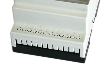
 GND (0V) OUT1 OUT2 OUT3 OUT4 OUT5 OUT6 OUT7 OUT8 + - GND")
3 -Universaldemux - 8 Kanal 3 Connection IN OUT 7-24V GND (0V) GND (0V) GND (0V) OUT1 OUT2 OUT3 OUT4 OUT5 OUT6 OUT7 OUT8 + - GND POWER
4 -Universaldemux - 8 Kanal 4 Addressing The starting address is adjustable via a DIP-Switch. Switch 1 has the valency 2 0 (=1), switch 2 has the valency 2 1 (=2) and so on finally switch 9 has the valency 2 8 (=256). The sum of the switches showing ON, represents the starting address Address Switch Address Switch LED-Display The LED is a multifunctional display. In the normal operation mode the LED lights non-stop. In this case the device is working. If the LED is permanently dark, there is no 512-input-signal. Furthermore the LED signals the operation status. In this case, the LED lights up in short pitches and then turns into off modus. The number of flashing signals is equal to the number of the error status: Error Error Description Status 1 No There is no -signal 2 Address error Please check if a valid -starting address is adjusted at the DIP-switch 3 -signal error An invalid input signal is determined, invert the signal line by changing switch 2 and 3 or use a twisted pair wire.
5 Operation mode -Universaldemux - 8 Kanal 5 The operation mode is selectable via a jumper. It is important to place the jumper in accordance to the following drawings to ensure a faultless function. It is not possible to combine the modes. Treshold value-output (no jumper placed) In the mode Treshold value there will be received 8 successive -channels. The belonging output will be set on OFF if the received value is between 0 and 127 and set on ON if the received value is between 128 and 255. Thereby output 1 is according to the first and output 8 is according to the last channel. Example: -value 1: 77 D = value 1: 219 D = Output 1: OFF Output 1: ON -value 2: 219 D = value 2: 77 D = Output 2: ON Output 2: OFF To invert the output-signal please use switch 10. Binary-output (only jumper is placed) In the binary-mode is only one -channel needed. The received value will be binary outputted at the output. Thereby output 1 is according to the first and output 8 is according to the last bit. Example: -value: 77 D = B -value: 219 D = B Output1: ON B Output 1: ON B Output 2: OFF B Output 2: ON B Output 3: ON B Output 3: OFF B Output 4: ON B Output 4: ON B Output 5: OFF B Output 5: ON B Output 6: OFF B Output 6: OFF B Output 7: ON B Output 7: ON B Output 8: OFF B Output 8: ON B To invert the output-signal please use switch 10.
6 -Universaldemux - 8 Kanal 6 Strobe-Control (only jumper is placed) The Universal-Demux gives out 8 controlling signals for stroboscope in the strobe-control-mode. Thereby each output will be triggered with one channel. The -value assignment is as follows: channel value Function 0-10 Stroboscope off Flashing speed slow fast Synchron flash Only one time the output will be triggered. Switch back and forth between the -value 0 and 255 to get a synchronized flashing. PWM-output (only jumper is placed) In the PWM-mode will be outputted 8 successive -channels as PWM-signal. Depending on the -value the PWM-signal will be generated in a range of 0-100%. To invert the output-signal please use switch 10. Servo-Control (only jumper is placed) The Universal Demux receives 8 successive channels and gives out a signal for triggering customary Servos. Thereby each output will be used to trigger one Servo. For operating with Servos is a 5V power supply necessary, in the rule. Please note, for the most Servos an additional resistor is needed which must be connected between the data line and +5V.


7 -Universaldemux - 8 Kanal 7 Equipment DIN-rail housing 700 Power supply 12V / 20W

8 -Universaldemux - 8 Kanal 8 CE-conformity This assembly (board) is controlled by a microprocessor and uses high frequency (8MHz). To get the characteristics of the assembly in relation to the CE-conformity, an installation in a compact metal casing is necessary. Risk-Notes You purchased a technical product. Conformable to the best available technology the following risks should not excluded: Failure risk: The device can drop out partially or completely at any time without warning. To reduce the probability of a failure a redundant system structure is necessary. Initiation risk: For the installation of the board, the board must be connected and adjusted to foreign components according to the device paperwork. This work can only be done by qualified personnel, which read the full device paperwork and understand it. Operating risk: The Change or the operation under special conditions of the installed systems/components could as well as hidden defects cause to breakdown within the running time. Misusage risk: Any nonstandard use could cause incalculable risks and is not allowed. Warning: It is not allowed to use the device in an operation, where the safety of persons depend on this device.
 without written permission or processed, multiplied or spread using electronic systems.")
9 4ALL GmbH Reiterweg 2A D Bochum Germany Copyright ALL GmbH All rights reserve. No part of this manual may be reproduced in any form (photocopy, pressure, microfilm or in another procedure) without written permission or processed, multiplied or spread using electronic systems. All information contained in this manual was arranged with largest care and after best knowledge. Nevertheless errors are to be excluded not completely. For this reason I see myself compelled to point out that I can take over neither a warranty nor the legal responsibility or any adhesion for consequences, which decrease/go back to incorrect data. This document does not contain assured characteristics. The guidance and the characteristics can be changed at any time and without previous announcement.
DMX Relais/Analog Interface 4. User Manual
 DMX Relais/Analog Interface 4 User Manual DMX Relais/Analog Interface 4 2 Description The DMX-Relais/Analog Interface 4 is designed for several controlling tasks. In total, 4 switching contacts and 4 analog
DMX-LED-DIMMER X9 HR 9x 16 BIT PWM per 10A
 DMX-LED-DIMMER X9 HR 9x 16 BIT PWM per 10A User Manual DMX-LED-Dimmer X9 HR 2 Description The DMX-LED-Dimmer X9 HR is especially designed for controlling RGB LED- Stripes. The dimmer has 9 High-Resolution
DMX-LED-DIMMER X9 HR 9x 16 BIT PWM per 10A
 DMX-LED-DIMMER X9 HR 9x 16 BIT PWM per 10A User Manual DMX-LED-Dimmer X9 HR 2 Description The DMX-LED-Dimmer X9 HR is especially designed for controlling RGB LED- Stripes. It has 9 High-Resolution PWM-Outputs
DMX-LED-DIMMER S. User Manual
 DMX-LED-DIMMER S User Manual DMX-LED-Dimmer S 2 Description The DMX-LED-Dimmer S is especially designed for controlling the R LED- Stripes. It has 4 PWM-Outputs which are autonomous controllable with DMX.
DMX-Splitter 4. User Manual
 -Splitter 4 User Manual -SPLITTER 4 2 Description The -Splitter 4 is a compact -Divider with one -Input signal which provides these at four galvanically isolated outputs. - Power supply via one power supply
ArtNet-LED-Dimmer 6 ArtNet-LED-Dimmer 6R
 ArtNet-LED-Dimmer 6 ArtNet-LED-Dimmer 6R User Manual Art-Net Designed by and Copyright Artistic Licence Holdings Ltd. ArtNet-LED Dimmer 6 / 6R 2 Description The ArtNet-LED Dimmer 6 / 6R is a compact LED
LIGHT REMOTE. for Android
 LIGHT REMOTE for Android LIGHT REMOTE for Android 2 Description The app LIGHT REMOTE for an easy controlling of LED-installations integrates a user-friendly design, an attractive arranged surface with
OPERATING MANUAL. DMX Demultiplexer 3012B Mk2
 last updated: 2007-03-08 OPERATING MANUAL DMX Demultiplexer 3012B Mk2 (C) SOUNDLIGHT 1995-2007 * ALL RIGHTS RESERVED * NO PART OF THIS MANUAL MAY BE REPRODUCED, DUPLICATED OR USED COMMERCIALLY WITHOUT
OPERATING MANUAL. DMX LED Current Dimmer 5004A-EP Mk2
 OPERATING MANUAL DMX LED Current Dimmer 5004A-EP Mk2 (C) SOUNDLIGHT 1996-2006 * ALL RIGHTS RESERVED * NO PART OF THIS MANUAL MAY BE REPRODUCED, DUPLICATED OR USED COMMERCIALLY WITHOUT THE PRIOR WRITTEN
EZCOM-1. PLC - to - AMS MESSAGE DISPLAY INTERFACE INSTALLATION AND OPERATING INSTRUCTIONS. Rev March, 2001
 EZCOM-1 PLC - to - AMS MESSAGE DISPLAY INTERFACE INSTALLATION AND OPERATING INSTRUCTIONS Rev 1.3 - March, 2001 CONTENTS Page INTRODUCTION 1 SPECIFICATIONS 1 LIST OF SUPPLIED ITEMS 1 INSTALLATION & TESTING
1. Overview. SSI-1016G interfaces with 24, 25 and 26 bit Temposonics SSI sensor. Block diagram. as PNP open collector output
 SSI-1016G Manual Caution: Specifications and outline may be changed without notice MTS Sensors Technology Corporation www.mtssensor.co.jp 2010.02.04 Rev. 1 1 Revision information 2007.03.12: Data-ready
GV 460 / GV 461 Impulse Splitters for Incremental Encoders with Potential Separation between Input and Outputs
 control motion interface GV 460 / GV 461 Impulse Splitters for Incremental Encoders with Potential Separation between Input and Outputs GV 480 / GV 481 Impulse Splitters for Incremental Encoders with all-around
LF101XF Six Function DCC Function Only Decoder Art. No February 2007
 LF101XF function decoder 1 The DIGITAL plus by Lenz LF101XF function decoder is suitable for use in all scales. Features include: Six function outputs rated at 200mA each with advanced function mapping.
ILDA Switch Automatic switching board for ILDA signals
 ILDA Switch Automatic switching board for ILDA signals Users manual (Please read before setting up) Last modified November 2nd t 2009 Published by: Mueller Elektronik, Hauptstrasse 86, D-78549 Spaichingen,
OPERATING MANUAL. DMX / DSI / DALI Dekoder 3004B-H Mk2
 OPERATING MANUAL DMX / DSI / DALI Dekoder 3004B-H Mk2 (C) SOUNDLIGHT 1996-2004 * ALL RIGHTS RESERVED * NO PART OF THIS MANUAL MAY BE REPRODUCED, DUPLICATED OR USED COMMERCIALLY WITHOUT THE PRIOR WRITTEN
Installation instruction FISTUNE antenna module Audi A6 Sedan 4G, Avant 4G
 Version 1.02 (29.09.2014) Installation instruction FISTUNE antenna module Audi A6 Sedan 4G, Avant 4G Article no. 39528 39528-1 39528-3 www.kufatec.de Kufatec GmbH & Co. KG Dahlienstr. 15 23795 Bad Segeberg
OPERATING MANUAL. DMX512 to DALI Dekoder 7044A-H Mk4
 last edited: 2014-08-12 OPERATING MANUAL DMX512 to DALI Dekoder 7044A-H Mk4 (C) SOUNDLIGHT 1996-2015 * ALL RIGHTS RESERVED * NO PART OF THIS MANUAL MAY BE REPRODUCED, DUPLICATED OR USED COMMERCIALLY WITHOUT
OPERATING MANUAL. DMX512 to DALI Dekoder 7044A-H Mk1
 last edited: 2010-07-24 OPERATING MANUAL DMX512 to DALI Dekoder 7044A-H Mk1 (C) SOUNDLIGHT 1996-2010 * ALL RIGHTS RESERVED * NO PART OF THIS MANUAL MAY BE REPRODUCED, DUPLICATED OR USED COMMERCIALLY WITHOUT
. The vertical pull-in range is approximately 10 Hz at fv = 60 Hz.
 Ordering number: EN2781B Monolithic Linear IC CRT Display Synchronization Deflection Circuit Overview The is a sync-deflection circuit IC dedicated to CRT display use. It can be connected to the LA7832/7833,
GMB101R BLACK BURST & PATTERN GENERATOR GMB101R-M 09/06/08
 4 fixed Black Burst outputs Test output in CV and Y/C Selection of 8 test patterns Output with correlated phase PAL / NTSC 1KHz balanced audio output GMB101R-M 09/06/08 1 1.0 OVERVIEW The GMB101R Black
Shutter BladeFader. Functional description Shutter BlackFader V1.0
 Shutter BladeFader Dimmer Shutter Functional description Shutter BlackFader V1.0 Fabrication and Marketing Licht-Technik Hagenbach & Grill Osterwaldstr. 9-10 80805 München Tel. 089-360528-0 Fax 089-360528-30
STROBOSCOPE LIGHT EFFECT KIT
 STROBOSCOPE LIGHT EFFECT KIT Easy to build stroboscope for general applications Flash frequency: 5 to 15 flashes per second Power supply: 110VAC Power consumption: 13W max. PCB dimensions: 50 x 75mm modifications
Model /29S RF Splitter
 Instruction Manual Model 1584-29/29S RF Splitter March 2013, Rev. 0 LNB VOLTAGE A B MODEL 1584 COMBINER CROSS TECHNOLOGIES INC. GND+DC ON Data, drawings, and other material contained herein are proprietary
Documentation VFD clock 8 a clock
 Documentation VFD clock 8 a clock This documentation is protected by our copyright. It must not be used for commercial purposes. Congratulations on your purchase of your VFD clock. To guarantee success
Industriefunkuhren. Technical Manual. OEM Sync-Module FE1000 (IRIG-B) ENGLISH
 ENGLISH") Industriefunkuhren Technical Manual OEM Sync-Module FE1000 (IRIG-B) ENGLISH Version: 07.02-24.03.2014 2 / 19 FE1000 IRIG-B Synchronisation - V07.02 IMPORTANT NOTES Version Number (Firmware / Manual) THE
Industriefunkuhren Technical Manual OEM Sync-Module FE1000 (IRIG-B) ENGLISH Version: 07.02-24.03.2014 2 / 19 FE1000 IRIG-B Synchronisation - V07.02 IMPORTANT NOTES Version Number (Firmware / Manual) THE
Industriefunkuhren. Technical Manual. IRIG-B Generator-Module for analogue / digital Signals of Type: IRIG-B / IEEE C / AFNOR NF S87-500
 Industriefunkuhren Technical Manual IRIG-B Generator-Module for analogue / digital Signals of Type: IRIG-B / IEEE C37.118 / AFNOR NF S87-500 Module 7628 ENGLISH Version: 02.01-06.03.2013 2 / 20 7628 IRIG-B
Nixie Clock Type Frank 2 Z570M
 Assembly Instructions And User Guide Nixie Clock Type Frank 2 Z570M Software version: 7R PCB Revision: 11 April 09-1 - 1. INTRODUCTION 1.1 About the clock Nixie clock type Frank 2 is a compact design with
TM Load-regulated locomotive decoder
 TM-56232 Load-regulated locomotive decoder User's manual 2011 BioDigit Ltd. All rights reserved. It is forbidden to reproduce and/or publish the contents of the present document in any form including electronic
User Manual Entry Line Industrial Fast Ethernet Switch 4x 10/100Base-TX, 1x 100Base-X Fiber Port 4x PoE+ up to 30W
 User Manual Entry Line Industrial Fast Ethernet Switch 4x 10/100Base-TX, 1x 100Base-X Fiber Port 4x PoE+ up to 30W Entry Line Fast Ethernet Switch Fast Ethernet Switch with PoE+ for Industrial Use Page
H2633IP-1 RELAY CARD K2633
 H2633IP-1 RELAY CARD K2633 Control up to 4 high-power circuits from a low-power drive circuit. Features & Specifications The connection of a few relays to the outputs of an electronic circuit might be
CHECK LINE. Model LS-36-LED. Stationary Stroboscope. Operating Manual BY ELECTROMATIC
 CHECK LINE BY ELECTROMATIC Stationary Stroboscope Model LS-36-LED Operating Manual Table of Contents 1.0 Introduction... 02 1.1 Unpacking 1.2 Optional Accessories 2.0 Safety Information... 3 3.0 Controls...
KONTROL channels DMX controller USER MANUAL. For safety, please read this user manual carefully before initial use.
 KONTROL192 192 channels DMX controller USER MANUAL For safety, please read this user manual carefully before initial use. Event Lighting reserves the right to revise the manual at any time. Information
Absolute Encoders Multiturn
 The Sendix 5863 and 5883 multiturn encoders with SSI or BiSS-C interface and optical sensor technology can achieve a resolution of max. 29 bits. A through hollow shaft up to 4 mm and a blind hollow shaft
Luminaire SIGNATURE SERIES
 Luminaire SIGNATURE SERIES SIGNATURE SERIES Luminaire Do you need a lot of light? Is your application a sky sign? With maximum brightness and pitch this is the go-to module for oversized channel letters
Turnout Decoder TD Maxi. User Manual - version 0.1.6
 Turnout Decoder TD Maxi - version by Copyright 2013 Tehnologistic SRL All rights reserved No part of this publication may be reproduced or transmitted in any form or by any means, electronic or mechanical,
STC-TC152USB-AT/AS/BTC/BSC STC-TB152USB-AT/AS/BTC/BSC Product Specification. Software Trigger USB 2.0 Color / Monochrome SXGA CCD Camera
 STC-TB152USB-AT/AS/BTC/BSC Product Specification Software Trigger USB 2.0 Color / Monochrome SXGA CCD Camera Safety Precautions CAUTION CAUTION RISK OF RISK ELECTRIC OF ELECTRIC SHOCK SHOCK DO NOT DO OPEN
Broadcast A/V Division VAC-HT12-KIT. 4K/UHD/HD/SD HDBaseT Extender Kit Video, Power, and Control over one CAT cable. User Manual
 Broadcast A/V Division VAC-HT12-KIT 4K/UHD/HD/SD HDBaseT Extender Kit Video, Power, and Control over one CAT cable User Manual Table of Contents Introduction... 3 Features... 3 Package Contents... 3 Specifications...
OPERATING MANUAL. DMX / Constant Current Dekoder 3706A-H Mk1 RDM
 last updated: 14-03-31 OPERATING MANUAL DMX / Constant Current Dekoder 3706A-H Mk1 RDM (C) SOUNDLIGHT 1996-2014 * ALL RIGHTS RESERVED * NO PART OF THIS MANUAL MAY BE REPRODUCED, DUPLICATED OR USED COMMERCIALLY
ES-Mega MegaBeans. Access Control System. User Manual. People in Motion
 ES-Mega MegaBeans Access Control System User Manual / Order No. Device People in Motion Contents 1. General description..3 2. Installation Instructions..4 3. Start-up..4 4. Audible signals..4 5. Operating
Owner s Manual. multiswitch Firmware-Version 1.06 OS- Version 1.02
 Owner s Manual multiswitch 1.41 Firmware-Version 1.06 OS- Version 1.02 The information contained in this manual is subject to change without prior notice. All rights reserved. Current as of: Juli 19 th
 APPLICATIONS typical application: Lighting automation Other applications of the SO and SI line of controllers: HVAC automation Industrial automation OVERVIEW The S Series are microprocessor based I/O controllers
POINTS POSITION INDICATOR PPI4
 POINTS POSITION INDICATOR PPI4 Monitors the brief positive operating voltage across points motors when they are switched Lights a corresponding led on a control panel to show the last operation of each
EGM Einthoven Goldberger Module Type 701
 Operating Instructions for the PLUGSYS Module EGM Einthoven Goldberger Module Type 701 ECG amplifier for bipolar extremity leads after Einthoven and unipolar extremity leads after Goldberger (Version:
Trusted 40 Channel Analogue Input FTA
 PD-T8830 Trusted Trusted 40 Channel Analogue Input FTA Product Overview The Trusted 40 Channel Analogue Input Field Termination Assembly (FTA) T8830 is designed to act as the main interface between a field
Dynamic Animation Cube Group 1 Joseph Clark Michael Alberts Isaiah Walker Arnold Li
 Dynamic Animation Cube Group 1 Joseph Clark Michael Alberts Isaiah Walker Arnold Li Sponsored by: Department of Electrical Engineering & Computer Science at UCF What is the DAC? The DAC is an array of
RoBoard Panel RP-089 Manual V1.0 The Heart of Robotics. Jul 2010 DMP Electronics Inc
 Manual V1.0 Jul 2010 DMP Electronics Inc Copyright The information in this manual is subject to change without notice for continuous improvement in the product. All rights are reserved. The manufacturer
GUIDE TO ASSEMBLY OF ERICA SYNTHS DELAY MODULE
 If you are reading this, most probably, you are about to build Erica Synths DIY DELAY module. The module is 4mm deep, skiff friendly, has solid mechanical construction and doesn t require wiring. Erica
VGA / Audio Extender Single CAT5 / CAT6 with RGB Delay Control & EQ
 VGA / Audio Extender Single CAT5 / CAT6 with RGB Delay Control & EQ Model #: VGA-C5A-SET 2010 Avenview Inc. All rights reserved. The contents of this document are provided in connection with Avenview Inc.
VGA & Audio Receiver SET over Single CAT5 with RGB Delay Control
 VGA & Audio Receiver SET over Single CAT5 with RGB Delay Control Model #: VGA-C5A-R 2010 Avenview Inc. All rights reserved. The contents of this document are provided in connection with Avenview Inc. (
Model 1421 Distribution Amplifier
 Model 1421 Distribution Amplifier Installation and Operating Instructions The 1421 Distribution Amplifier provides four independent, wide bandwidth outputs from one video input. The unit is color compatible
LEVEL ADJUST POWER Shiloh Road Alpharetta, Georgia (770) FAX (770) Toll Free
 FAX (770) Toll Free") Instruction Manual Model 1200-07 Amplifier September 2010 Rev A MONITOR J1 LEVEL ADJUST POWER MODEL 1200 AMPLIER CROSS TECHNOLOGIES, INC. Data, drawings, and other material contained herein are proprietary
Instruction Manual Model 1200-07 Amplifier September 2010 Rev A MONITOR J1 LEVEL ADJUST POWER MODEL 1200 AMPLIER CROSS TECHNOLOGIES, INC. Data, drawings, and other material contained herein are proprietary
LED DRIVERS. LQC4D-V1 4 channels. User Manual FEATURES
 pag. 1/13 FEATURES Outputs: 4 x channels BUS+SEQUENCER+FADER+DIMMER+DRIVER Input: DC 12/24/48 Vdc BUS Command: DALI LOCAL Command: 4x N.O. push button (with or without memory), 0-10V, 1-10V Controls: dimmer,
M150SP USER S AND INSTALLER S MANUAL. v2.0 REV. 03/2017
 M150SP USER S AND INSTALLER S MANUAL v2.0 REV. 03/2017 00. CONTT 01. SAFETY INSTRUCTIONS INDEX 01. SAFETY INSTRUCTIONS STANDARDS TO FOLLOW 02. THE DEVICE TECHNICAL SPECIFICATIONS VISUAL ASPECT CONNECTORS
VU Meter Buffer DIY Kit
 VU Meter Buffer DIY Kit Warning This document is distributed for educational purposes only. This equipment operates at potentially lethal voltages. Only trained, qualified personnel should operate, maintain,
Instruction Manual Model BlockUpconverter
 Instruction Manual Model 2115-55 BlockUpconverter June 2009 - Rev. 0 MODEL 2115 UPCONVERTER CROSS TECHNOLOGIES INC. EXT 10MHZ ALARM POWER Data, drawings, and other material contained herein are proprietary
VGA / Audio Extender Single CAT5 / CAT6 with RGB Delay Control & EQ
 AV Connectivity, Distribution And Beyond... VIDEO WALLS VIDEO PROCESSORS VIDEO MATRIX SWITCHES EXTENDERS SPLITTERS WIRELESS CABLES & ACCESSORIES VGA / Audio Extender Single CAT5 / CAT6 with RGB Delay Control
Instruction Manual Model # Block Upconverter
 Instruction Manual Model 2115-278# Block Upconverter August 2018, Rev. A MODEL 2115 UPCONVERTER CROSS TECHNOLOGIES INC. EXT 10MHZ ALARM POWER Data, drawings, and other material contained herein are proprietary
INSTRUCTION MANUAL MODEL 2710 SUBCARRIER DEMODULATOR
 INSTRUCTION MANUAL MODEL 2710 SUBCARRIER DEMODULATOR Data, drawings, and other material contained herein are proprietary to Cross Technologies, Inc., and may not be reproduced or duplicated in any form
DMC550 Technical Reference
 DMC550 Technical Reference 2002 DSP Development Systems DMC550 Technical Reference 504815-0001 Rev. B September 2002 SPECTRUM DIGITAL, INC. 12502 Exchange Drive, Suite 440 Stafford, TX. 77477 Tel: 281.494.4505
AI-1664LAX-USB. Features. 100KSPS 16-bit Analog Input Unit for USB AI-1664LAX-USB 1. Ver.1.01
 100KSPS 16-bit Analog Unit for USB AI-1664LAX-USB * Specifications, color and design of the products are subject to change without notice. This product is a USB2.0-compliant analog input unit that extends
VGA, Audio & RS232 Extender SET over Single CAT5 with RGB Delay Control & IR Pass Through
 VGA, Audio & RS232 Extender SET over Single CAT5 with RGB Delay Control & IR Pass Through Model #: VGA-C5ARS-SET 2010 Avenview Inc. All rights reserved. The contents of this document are provided in connection
PRO-HDMI2HD. HDMI to SDI/3G-HD-SD Converter. User Manual. Made in Taiwan
 PRO-HDMI2HD HDMI to SDI/3G-HD-SD Converter User Manual Made in Taiwan rev.1008 103 Quality Circle, Suite 210 Huntsville, Alabama 35806 Tel: (256) 726-9222 Fax: (256) 726-9268 Email: service@pesa.com Safety
3G/HD/SD-SDI to HDMI Converter
 3G/HD/SD-SDI to HDMI Converter Model #: 3G/HD/SD-SDI to HDMI Converter 2010 Avenview Inc. All rights reserved. The contents of this document are provided in connection with Avenview Inc. ( Avenview ) products.
CardModule. Reference Manual. Series C DA Channel SDI to CVBS Converter. Version 1.0
 Reference Manual C DA 5005 5 Channel SDI to CVBS Converter Version 1.0 Series 5000 CardModule LYNX Technik AG Brunnenweg 3 D-64331 Weiterstadt Germany www.lynx-technik.com Information in this document
VGA to DVI Extender over Fiber SET
 VGA to DVI Extender over Fiber SET Model #: FO-VGA-DVI 2011 Avenview Inc. All rights reserved. The contents of this document are provided in connection with Avenview Inc. ( Avenview ) products. Avenview
Flarm LED indicator. Version 1.13
 Flarm LED indicator Version 1.13 LXNAV d.o.o. Kidričeva 24, 3000 Celje, Slovenia tel +386 592 33 400 fax +386 599 33 522 info@lxnav.com www.lxnav.com 1 Important Notices 3 1.1 Limited Warranty 3 2 Packing
TIL311 HEXADECIMAL DISPLAY WITH LOGIC
 TIL311 Internal TTL MSI IC with Latch, Decoder, and Driver 0.300-Inch (7,62-mm) Character Height Wide Viewing Angle High Brightness Left-and-Right-Hand Decimals Constant-Current Drive for Hexadecimal Characters
User Manual KUNBUS-PRS
 User Manual KUNBUS-PRS DO0236R00 14/09/2016 Table of content KUNBUS Table of content 1 Working with PRS... 3 1.1 Validity... 3 1.2 User... 3 1.3 Symbols... 3 1.4 Safe use... 4 1.5 Limitation of Liability...
Version-E Manual
 Version-E170619 Manual Important Information General Before using your ALGE-TIMING device read the complete manual carefully. It is part of the device and contains important information about installation,
P VD 5000 G Video Media Processor (Frame Synchronizer) P VD 5000 G. REF loop. REF in. SDI in 2. SDI in 1. SDI 2 loop. SDI 1 loop. SDI out 2.
 P VD 5000 G. REF loop. REF in. SDI in 2. SDI in 1. SDI 2 loop. SDI 1 loop. SDI out 2.") Version 1.0 Reference Manual P VD 5000 G Video Media Processor (Frame Synchronizer) P VD 5000 G Series 5000 CardModule LYNX Technik AG REF in SDI in 1 SDI 1 loop SDI out 1 Delay out REF loop SDI in 2 SDI
Version 1.0 Reference Manual P VD 5000 G Video Media Processor (Frame Synchronizer) P VD 5000 G Series 5000 CardModule LYNX Technik AG REF in SDI in 1 SDI 1 loop SDI out 1 Delay out REF loop SDI in 2 SDI
O P E R A T I O N M A N U A L. RF-Reader. Stand-alone-Reader Leser 2plus with RS-232 interface
 O P E R A T I O N M A N U A L Version 01/05 RF-Reader Stand-alone-Reader Leser 2plus with RS-232 interface Important! Read by all means! To maintain the perfect shipping conditions and to ensure safe operation
User Manual Digital Stroboscope
 Page 15/04/14 V1.0 Table Of Contents 1. Features 3 2. Specifications 3 & 4 2-1 General Specification 3 & 4 2-2 Flash Tube Specification 4 3. Front Panel Description 5 3-1 Flash Tube 5 3-2 Display 5
VIPA Accessories. ProfiHub B BE00 Manual
 VIPA Accessories ProfiHub B5 973-5BE00 Manual HB151E Rev. 12/04 January 2012 Copyright VIPA GmbH. All Rights Reserved. This document contains proprietary information of VIPA and is not to be disclosed
CardModule. Reference Manual. Series P VD 5005 G Video Media Processor (Frame Synch with Audio Processing for embedded Audio) Version 1.
 Version 1.") Version 1.4 Reference Manual P VD 5005 G Video Media Processor (Frame Synch with Audio Processing for embedded Audio) Series 5000 CardModule LYNX Technik AG Brunnenweg 3 D-64331 Weiterstadt Germany www.lynx-technik.com
Version 1.4 Reference Manual P VD 5005 G Video Media Processor (Frame Synch with Audio Processing for embedded Audio) Series 5000 CardModule LYNX Technik AG Brunnenweg 3 D-64331 Weiterstadt Germany www.lynx-technik.com
Marshall Electronics. Broadcast A/V Division VAC-HT12-KIT. 4K HDBaseT Extender Kit. User Manual
 Marshall Electronics Broadcast A/V Division VAC-HT12-KIT 4K HDBaseT Extender Kit User Manual VAC-HT12-KIT Manual Table of Contents Introduction... 3 Features... 3 Package Contents... 3 Specifications...
MICROMASTER Encoder Module
 MICROMASTER Encoder Module Operating Instructions Issue 01/02 User Documentation Foreword Issue 01/02 1 Foreword Qualified Personnel For the purpose of this Instruction Manual and product labels, a Qualified
34MD Series. Motor/Driver Combination. User s Guide E. Landon Drive Anaheim, CA
 34MD Series Motor/Driver Combination User s Guide A N A H E I M A U T O M A T I O N 4985 E. Landon Drive Anaheim, CA 9287 e-mail: info@anaheimautomation.com (714) 992-699 fax: (714) 992-471 website: www.anaheimautomation.com
Wind Indicator LED. Contents. Instruction for Use xx.x00, x08, xx.10
 Wind Indicator LED Instruction for Use 4.3225.xx.x00, 4.3225.10.x08, 4.3225.xx.10 Contents 1. General Information 2 1.1 Versions of the Indicator 2 1.2 Elements of the Indicator 3 2. Installation 4 2.1
DIGITAL STROBOSCOPE OPERATION MANUAL. Model : DT-2239A
 DIGITAL STROBOSCOPE Model : DT-2239A Your purchase of this DIGITAL STROBOSCOPE marks a step forward for you into the field of precision measurement. Although this STROBOSCOPE is a complex and delicate
Next Generation 4800 LUX. RT STROBE pocket LED. The ultra high-performance, hand-held stroboscope. Superfast. Superbright. Superlight. Supertight.
 Safe measurement, indication and control of rotational speed RT STROBE pocket LED The ultra high-performance, hand-held stroboscope. Superfast. Superbright. Superlight. Supertight. Next Generation 4800
MINI MCR-SL-F-UI-NC. Frequency transducers. Data sheet. 1 Description
 Frequency transducers Data sheet 105_en_01 PHOENIX CONTACT 01-08-19 1 Description Configurable -way isolated frequency transducer. The device is suitable for the connection of NAMUR proximity sensors (IEC
User manual BETSO TCD-1. 1 Compact Time Code display. 1 Copyright BETSO ELECTRONICS Ltd.
 1 Compact Time Code display 1 Copyright BETSO ELECTRONICS Ltd. Contents 1. Product description...3 2. Top features...3 3. Control elements...4 4. Charging of accumulators...5 5. External power...5 6. Turning
DisplayPort to VGA Converter
 DisplayPort to VGA Converter Model #: C-DP-VGA 2010 Avenview Inc. All rights reserved. The contents of this document are provided in connection with Avenview Inc. ( Avenview ) products. Avenview makes
Industriefunkuhren. Technical Manual. Model 7248/7248RC. Fibre Optic Converter Board ENGLISH
 Industriefunkuhren Technical Manual Fibre Optic Converter Board Model 7248/7248RC ENGLISH Version: 01.00-04.05.2007 2 / 16 7248/7248RC Fiber Optic Converter Board - V01.00 INPORTANT NOTES Downloading Technical
"shell" digital storage oscilloscope (Beta)
") "shell" digital storage oscilloscope (Beta) 1. Main board: solder the element as the picture shows: 2. 1) Check the main board is normal or not Supply 9V power supply through the connector J7 (Note: The
"shell" digital storage oscilloscope (Beta) 1. Main board: solder the element as the picture shows: 2. 1) Check the main board is normal or not Supply 9V power supply through the connector J7 (Note: The
KACO-display. Wireless Solar Monitoring System. Operating Instructions KACO-display. full of energy...
 Wireless Solar Monitoring System. Operating Instructions KACO-display full of energy... KACO-display provides high-technology monitoring of your valuable photovoltaic installation. It shows the desired
System Power Supply 4. User Guide
 System Power Supply 4 User Guide 2017 Schnick-Schnack-Systems GmbH Situation at August 2017: All technical data as well as the weight and dimension information were carefully created errors reserved. Any
Modular DAA with 2/4 Wire Convertor. XE0002D Block Diagram
 XE0002D August 2005 Modular DAA with 2/4 Wire Convertor Description The XE0002D is a compact DAA module designed for applications requiring voice, data or fax transfer. It complies with FCC Part 68 rules
Product Information. LIC 4113 LIC 4193 Absolute Exposed Linear Encoders
 Product Information LIC 4113 LIC 4193 Absolute Exposed Linear Encoders November 2016 LIC 4113, LIC 4193 Absolute linear encoder for measuring lengths up to 3 m Measuring steps to 0.001 µm Measuring standard
Mal-2 assembly guide v1.0
 Mal-2 assembly guide v.0 SONIC POTIONS Schematic and BOM The BOM can be found on Google Docs Prepare the PCB Separate the PCBs using some pliers. PCB We start with the lower PCB and assemble it beginning
1x4, 1x8, 1x12, 1x16 VGA Extender / Splitter over Single CAT5
 1x4, 1x8, 1x12, 1x16 VGA Extender / Splitter over Single CAT5 User s Guide Models VGA-C5-SP-4 VGA-C5-SP-8 VGA-C5-SP-12 VGA-C5-SP-16 2009 Avenview Inc. All rights reserved. The contents of this document
Configuration Vestas VMP3500
 Configuration Vestas VMP3500 1. Table of contents 1. Table of contents... 2 2. Introduction... 3 3. Vestas turbines (RCS)... 4 3.1. VMP 3500 controller... 4 3.2. Communication with the CT3230 current loop
VGA & RS232 Extender SET over Single CAT5 with RGB Delay Control
 VGA & RS232 Extender SET over Single CAT5 with RGB Delay Control Model #: VGA-C5RS-SET 2010 Avenview Inc. All rights reserved. The contents of this document are provided in connection with Avenview Inc.
Operating Instructions
 Operating Instructions SteadiQ 2009-351 Read This Manual before You Attempt to use this Instrument WARNING: Dangerous Voltages Present - NO Serviceable Parts Inside Instrument should be serviced by qualified
4, 8, 16 Port VGA/ Audio Extender / Splitter With Local Output with SPDIF Model #: VGA-C5SP-8
 4, 8, 16 Port VGA/ Audio Extender / Splitter With Local Output with SPDIF Model #: VGA-C5SP-8 2010 Avenview Inc. All rights reserved. The contents of this document are provided in connection with Avenview
ELECTRICAL ENGINEERING DEPARTMENT California Polytechnic State University
 EECTRICA ENGINEERING DEPARTMENT California Polytechnic State University EE 361 NAND ogic Gate, RS Flip-Flop & JK Flip-Flop Pre-lab 7 1. Draw the logic symbol and construct the truth table for a NAND gate.
Vorne Industries. 87/719 Analog Input Module User's Manual Industrial Drive Itasca, IL (630) Telefax (630)
 Telefax (630)") Vorne Industries 87/719 Analog Input Module User's Manual 1445 Industrial Drive Itasca, IL 60143-1849 (630) 875-3600 Telefax (630) 875-3609 . 3 Chapter 1 Introduction... 1.1 Accessing Wiring Connections
Vorne Industries 87/719 Analog Input Module User's Manual 1445 Industrial Drive Itasca, IL 60143-1849 (630) 875-3600 Telefax (630) 875-3609 . 3 Chapter 1 Introduction... 1.1 Accessing Wiring Connections
3B SCIENTIFIC PHYSICS
 B SCIENTIFIC PHYSICS Triode S 11 Instruction sheet 1/15 ALF 1 5 7 1 Guide pin Connection pins Cathode plate Heater filament 5 Grid Anode 7 -mm plug for connecting anode 1. Safety instructions Hot cathode
DMP 339. Pressure Transmitter. with G ¼" flush diaphragm. Pressure Transmitter. Industrial. accuracy according to IEC 60770: 0.
 DMP 9 Industrial Pressure Transmitter with G ¼" flush diaphragm accuracy according to IEC 60770: 0.5 % FSO Industrial Pressure Transmitter DMP 9 Nominal pressure from 0... 60 bar up to 0... 600 bar Output
HDBaseT EXTENDER B-540-EXT-230-RS INSTALLATION MANUAL
 EXTENDER B-540-EXT-230-RS INSTALLATI MANUAL IMPORTANT SAFETY INSTRUCTIS To reduce the risk of fire or electric shock, read and follow all instructions and warnings in this manual. Keep this manual for