INSTALLATION GUIDE. Axle Weighing Truck Scale. 60,000 lb x 20 lb Factory Calibrated Includes Pre-interfaced Wireless Remote LED Scoreboard Displays
|
|
|
- Jessica Day
- 5 years ago
- Views:
Transcription


1 INSTALLATION GUIDE 60,000 lb x 20 lb Factory Calibrated Includes Pre-interfaced Wireless Remote LED Scoreboard Displays V 1.0

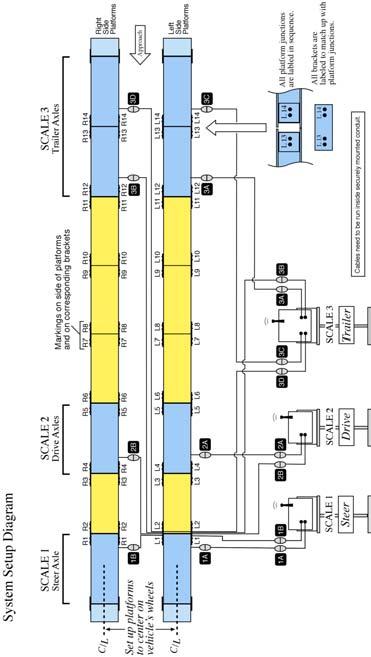
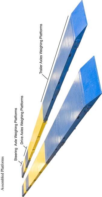
2 OVERVIEW TOOLS REQUIRED Forklift and block Prybar Wrenches: #8 allen wrench, 15/16 & 30mm ratchet or pneumatic wrench ESTIMATED TIME REQUIRED TO SET UP THE SYSTEM hrs RECOMMENDED NUMBER OF PERSONS TO SET UP THE SYSTEM Two ASSEMBLY SYNOPSIS Assembly of the scale is a very straightforward procedure. Most of the required assembly time is in positioning the large, heavy platforms. The platforms are labeled in sequence at each junction. Once in place, the platforms are secured together with brackets. All brackets are labeled to match up to the platform junctions. The end ramps are secured to the platforms with a single bolt. Each scale platform has a cable that runs directly to one of the three digital indicators. All cables have quick connectors that are plainly labeled. The cables from the right side weighing platforms pass through the left side platforms (at a junction) and then connect to the digital indicators. The cables from the left side weighing platforms run directly to the digital indicators. The digital indicators display the weight of the steering axle, the drive axles, and the trailer axles. The Trailer Axles Indicator displays three weights: Trailer Axle Scale 1, Trailer Axle Scale 2, and the total weight of both Trailer Axle Scales. The wireless remote displays are factory-interfaced and require no setup (related digital indicator must be operating). 2
3 Important Note: The location of the scale installation is very important. The scale MUST be installed on a level concrete surface. Never install the scale on asphalt. Asphalt is not hard enough to take heavy loads and the scale will sink into the asphalt over time. Ample space must be available for vehicles to accurately approach and exit the platforms. 1. UNPACK & VERIFY CONTENTS Below is a list of the parts and quantities: Weighing Platforms, Blue (8) Ramps, Blue (4) Spacer Platforms, Yellow (8) Platform Connector Brackets (28) Bracket Bolts (112) ¾ Anchor Bolts for Platforms (64) ½ Anchor Bolts for Digital Indicator Stands (12) 100 ft Connecting Cables with Quick-connect Sockets (4) 50 ft Connecting Cables with Quick-connect Sockets (4) Digital Indicators (3) Digital Indicator Stands (3) Wireless Scoreboard Remote Displays (3) 2. PLAN YOUR SET UP Refer to the System Setup Diagram on page 8 for planning your set up. Determine the track width of the vehicles to be weighed on the scale, as this will determine the distance required between the left and right platforms. After the locations of the platforms have been determined, it may be helpful to snap chalk lines to refer to when fork lifting the platforms into position. 3. FORKLIFT THE PLATFORMS INTO POSITION Refer to the System Setup Diagram on page 8 when fork lifting the platforms into position. Locate the two blue weighing platforms labeled R14 and L14. Per the System Setup Diagram, place these two platforms at the approach end of the platform arrangement. Following the System Setup Diagram, continue placing the left and right platforms into position, matching the end labels in sequence. Be sure to continually check the platform positions for running in a straight line, and for consistent spacing between the left side and right side platforms. 4. ATTACH THE PLATFORM BRACKETS Refer to the System Setup Diagram on page 8 when attaching the platform brackets. Place all brackets into positions as marked to match up to the platform junctions 3
, and then securely tighten down all brackets. 5.")
4 (when attaching, the brackets can be turned over so that the markings face inward). Loosely bolt all brackets into position. Recheck that all platforms are in correct position (a pry bar may be useful for making small adjustments to the platform positions), and then securely tighten down all brackets. 5. ATTACH THE FOUR RAMPS Place the ramps into position and securely bolt down to the end platforms. 6. CHECK PLATFORMS FOR ROCKING Check all weighing platforms for corner-to-corner rocking. Shim as needed. 7. LOOSEN AND ADJUST THE CHECKING BOLTS ON THE WEIGHING PLATFORMS Three checking bolts are located at the end of each weighing platform. These bolts are tightened down for shipping. IMPORTANT In order for the scales to work properly, all checking bolts on all weighing platforms must be adjusted after receiving the scale. Adjust the checking bolts on each platform as follows: Using a #8 allen wrench, remove all the weighing platform access panels. Referring to the diagram below: Back out the two side bolts, and adjust to a 1/2 gap between the end of the bolt and the internal frame. Back out the end nut, and adjust to 1/2 gap between the nut and the inner frame floor. Replace all access panel covers and securely fasten. 4
5 8. ATTACH THE CABLES CONNECTING THE WEIGIHING PLATFORMS TO THE DIGITAL INDICATORS Refer to the System Setup Diagram on page 8 when connecting the cables. NOTE: Cables should be run through securely mounted conduit. The customer determines the conduit installation. Conduit installation is not covered in this Assembly Guide. Connecting the cables is a simple procedure. The eight cables are equipped with quick-connect sockets at both ends, enabling easy connection to the weighing platforms and to the digital indicators. All weighing platforms have quick-connect sockets on short cables. For protection during shipping, these connectors are tucked inside the platform. Hang tags are attached to the cables. Gently pull out the short quick-connect cable through the cable exit opening on each weighing platform. Locate the four 100 ft. cables with connectors labeled 3A, 3B, 3C and 3D. ATTACH THE CABLES TO THE RIGHT SIDE WEIGHING PLATFORMS Cables 1B, 2B, 3B and 3D connect to the Right Side Weighing Platforms, and pass through the Left Side Platforms at junction L1-L2, then run to the digital indicators located on the left side of the system for viewing by the driver of the truck being weighed. Attach the long cable connector 1B to the matching weighing platform connector 1B. Attach the long cable connector 2B to the matching weighing platform connector 2B. Attach the long cable connector 3B to the matching weighing platform connector 3B. Attach the long cable connector 3D to the matching weighing platform connector 3D. Pass the cables through the Left Side Platforms at junction L1-L2 (between the blue Steering Axle Scale and the yellow spacer platform). Do not connect to digital indicators at this point. 5
6 Locate the four 50 ft. cables with connectors labeled 1A, 2A, 3A and 3C. ATTACH THE CABLES TO THE LEFT SIDE WEIGHING PLATFORMS Cables 1A, 2A, 3A and 3C connect to the Left Side Weighing Platforms, and run directly to the digital indicators. Attach the long cable connector 1A to the matching weighing platform connector 1A. Attach the long cable connector 2A to the matching weighing platform connector 2A. Attach the long cable connector 3A to the matching weighing platform connector 3A. Attach the long cable connector 3C to the matching weighing platform connector 3C. 9. CONNECT WEIGHING PLATFORM CABLES TO THE DIGITAL INDICATORS Refer to the System Setup Diagram on page 8 when connecting the cables. IMPORTANT Do not mount the digital indicators on stands at this point. Indicators mounted on stands that have not been anchored are prone to severe damage from being knocked over. Place the indicators on a bench or cart for initial connecting and testing of the system. Before plugging in the digital indicators to 110VAC, connect all weighing platform cables to the digital indicators, being sure to match up all of the connector labels, i.e., the 1A cable connects to the 1A connector on the Steering Axle digital indicator. 11. POWER ON AND TEST THE SYSTEM Plug the digital indicators in to 110VAC. Power on the digital indicators by pressing the red ON key and allow the system to warm up several seconds. Plug in the wireless scoreboard remote displays to 110 VAC. After a few moments, all displays should read 0 lb. If not, press the ZERO key (not the number 0 key). If displays do not read 0 lb, recheck all connections. Be sure to power off the indicators before making any changes to the connections. If for any reason the displays will not read 0 lb, contact Triner Scale technical support toll free at (800) , Mon-Fri 8:00 4:30 CST. With all displays indicating 0 lb, place at least 200 lb of weight on each of the eight weighing platforms. The steering axle scale indicator and wireless remote will display the total weight placed on platforms 1A and 1B. The drive axles scale indicator and wireless remote will display the total weight placed on platforms 2A and 2B. 6
7 The trailer axles scale indicator will display: the total weight placed on platforms 3A and 3B, the total weight placed on platforms 3C and 3D, and the total of all weights placed on platforms 3A through 3D. The wireless remote will display the total of all weights placed on platforms 3A through 3D. 11. ANCHOR THE SYSTEM AND MOUNT THE DISPLAYS After rechecking the platforms for corner-to-corner rocking and making any needed adjustments, anchor the platforms using the provided ¾ anchor bolts. Weighing platform anchor locations are under the access panels. Spacer platforms have anchor tabs. Anchor the digital indicator stands using the provided ½ anchor bolts. Mount the indicators to the anchored stands. Mount the wireless scoreboard remote displays as required. Triner Scale Toll Free Technical Support Mon-Fri 8:00 4:30 CST (800) Triner Scale & Mfg. Co., Inc Hacks Cross Road Olive Branch, MS Tel (662) Fax (662) Toll Free (800)
8 8
9 9
10 Triner Scale General Warranty* What is Covered: Triner Scale warrants to the first end user customer of the Triner Scale product enclosed with this limited warranty statement that the product, if purchased and used in the United States, conforms to the manufacturer's specifications and will be free from defects in workmanship and materials for a period of one (1) year from the date of original purchase. What Triner Scale Will Do to Correct Problems: Should your Triner Scale product prove defective during the warranty period, please call Triner Scale at (800) for warranty repair instructions and return authorization. Triner Scale will, at its option, repair or replace on an exchange basis the defective unit as follows: PARTS New or comparable rebuilt parts in exchange for defective parts for one (1) year after original purchase. LABOR Carry-In or mail in service for 90 days from the date of original purchase. Labor and shipping cost after the 90 day period will be charged to you. If you are authorized by Triner Scale to ship the product to Triner Scale for repair, it is your responsibility to securely package the product in its original container or an equivalent and provide proof of the date of original purchase. You will be responsible for shipping costs to Triner Scale repair facility. When warranty service involves the exchange of the product or a part, the exchanged product may be new or previously repaired to the Triner Scale standard of quality. Exchange or replacement products or parts assume the remaining warranty period of the product covered by this limited warranty. What this Warranty Does Not Cover: This warranty covers only consumer use in the United States. Triner Scale is not responsible for warranty service should the Triner Scale label or logo or the serial number be removed or the product fail to be properly maintained or fail to function properly as a result of misuse, abuse, improper installation, neglect, improper shipping, damage caused by disasters such as fire, flood, and lightning, improper electrical current, interaction with non-triner Scale products, or service other than a Triner Scale Authorized Service. Packaging and shipping costs incurred in presenting your Triner Scale product for warranty service are your responsibility. If a claimed defect cannot be identified or reproduced in service, you will be held responsible for costs incurred. 10
11 THE WARRANTY AND REMEDY PROVIDED ABOVE ARE EXCLUSIVE AND IN LIEU OF ALL OTHER EXPRESS OR IMPLIED WARRANTIES INCLUDING, BUT NOT LIMITED TO, THE IMPLIED WARRANTIES OF MERCHANTABILITY OR FITNESS FOR A PARTICULAR PURPOSE. SOME LAWS DO NOT ALLOW THE EXCLUSION OF IMPLIED WARRANTIES. IF THESE LAWS APPLY, THEN ALL EXPRESS AND IMPLIED WARRANTIES ARE LIMITED TO THE WARRANTY PERIOD IDENTIFIED ABOVE. UNLESS STATED HEREIN, ANY STATEMENTS OR REPRESENTATIONS MADE BY ANY OTHER PERSON OR FIRM ARE VOID. EXPECT AS PROVIDED IN THIS WRITTEN WARRANTY, NEITHER TRINER SCALE NOR ITS AFFILIATES SHALL BE LIABLE FOR ANY LOSS, INCONVENIENCE, OR DAMAGE, INCLUDING DIRECT, SPECIAL, INCIDENTAL OR CONSEQUENTIAL DAMAGES, RESULTING FROM THE USE OR INABILITY TO USE THE TRINER SCALE PRODUCT, WHETHER RESULTING FROM BREACH OF WARRANTY OR ANY OTHER LEGAL THEORY. No terms, condition, underpstanding, or agreements, purporting to modify the terms of this warranty shall have any legal effect unless made in writing and signed by a corporate officer of the seller. This warranty gives you specific legal rights, and you my have other rights which vary from jurisdiction to jurisdiction. * Warranties may vary on some products purchased through Triner Scale. Contact Triner Scale directly for confirmation of warranty on your product(s). 11
WID-DL74 WID-DL74 BLP WID. Designed for. Installation guide for workitdesk interactive table for. BrightLink Pro
 WID-DL74 WID-DL74 BLP WID Designed for BrightLink Pro Installation guide for workitdesk interactive table BrightLink Pro for Mounting the table unit 1 Unpack boxes 1 of 4 (Mobile base) and 2 of 4 (Motorized
Metal and Glass TV Stand for TVs up to 65 or 110 lbs. NS-HMG1856
 USER GUIDE Metal and Glass TV Stand for TVs up to 65 or 110 lbs. NS-HMG1856 SAFETY INFORMATION AND SPECIFICATIONS...2 PACKAGE CONTENTS: PARTS...3 PACKAGE CONTENTS: HARDWARE...4 ASSEMBLY INSTRUCTIONS...5
REQUIRED TOOLS. Wire cutters Razor blade Soldering iron Pliers 11/16 Wrench for Tube 18mm Wrench for Ring
 S9122 PWS BNC MALE CABLE MOUNT COMPRESSION CONNECTOR S9022 PWS N TYPE MALE CABLE MOUNT COMPRESSION CONNECTOR S9322 PWS TNC MALE CABLE MOUNT COMPRESSION CONNECTOR The PWS S9122 is a BNC male cable mount
APSPB PUSH BUTTON ZERO Installation Manual
 APSPB PUSH BUTTON ZERO Installation Manual CARDINAL SCALE MFG. CO. 8527-0579-0M Rev A 203 E. Daugherty, Webb City, MO 64870 USA Printed in USA 12/14 Ph: 417-673-4631 Fax: 417-673-2153 www.detectoscale.com
AUDIO WIRELESS. with IR Extender Feature OWNER S MANUAL SENDER T CAT. NO
 /V WIRELESS AUDIO UDIO/V /VIDEO SENDER with IR Extender Feature OWNER S MANUAL SENDER 15-2572T CAT. NO. 15-2572 SENDER 15-2572T FCC CAUTION THIS DEVICE COMPLIES WITH PART 15 OF THE FCC RULES. OPERATION
TV Lift System Model CL-65 Installation Instructions
 TV Lift System Model CL-65 Installation Instructions Contact: Support@Nexus21.com Toll Free: (866) 500-5438 Phone: (480) 951-6885 Fax: (480) 951-6879 Revised: 01/17/17 Below is a parts list describing
ezcinema Plus Series
 ezcinema Plus Series Portable Floor Pull-Up USER S GUIDE Rev062510-JA www.elitescreens.com info@elitescreens.com Precautions: Warning! damage can result from operational errors if the enclosed precautions
INSTALLATION INSTRUCTIONS FOR
 INSTALLATION INSTRUCTIONS FOR MODEL 2240LED www.sportablescoreboards.com 1 Table of Contents 8 X 7 INDOOR SCOREBOARD... 3 THE SCOREBOARD SYSTEM SHOULD INCLUDE THE FOLLOWING PARTS:... 3 INSTRUCTIONS FOR
INSTALLATION INSTRUCTIONS FOR. MODEL 2230LED
 INSTALLATION INSTRUCTIONS FOR MODEL 2230LED www.sportablescoreboards.com 1 Table of Contents MODEL 2230LED... 3 8 X 4 INDOOR SCOREBOARD... 3 THE SCOREBOARD SYSTEM SHOULD INCLUDE THE FOLLOWING PARTS:...
ST-4000 SIGNAL LEVEL METER
 ST-4000 SIGNAL LEVEL METER Table of Contents Features / Specifications.... 1 Keypad Illustration....... 2 Keypad Controls.... 2 Getting Started: Powering the Meter.... 3 Quick Use Instructions.. 3 Main
Satellite Receiver. Chapter REMOTE CONTROL USING THE MENUS USING TEXT FIELDS. About Your Satellite Receiver. What you ll find in this chapter:
 Satellite Receiver About Your Satellite Receiver Chapter What you ll find in this chapter: REMOTE CONTROL USING THE MENUS USING THE MENUS USING TEXT FIELDS 3 Chapter 2 Remote Control REMOTE CONTROL The
WINEGARD INSTALLATION MANUAL. Model GM Carryout Ladder Mount for mounting pipes with outer diameters between 1 to 1-1/8
 WINEGARD INSTALLATION MANUAL Model GM-3000 Carryout Ladder Mount for mounting pipes with outer diameters between 1 to 1-1/8 WARNING: DO NOT USE THE LADDER MOUNT AS A STEP! NOT INTENDED FOR USE WITH THE
ST-4000D SIGNAL LEVEL METER
 ST-4000D SIGNAL LEVEL METER Rev 100606 Table of Contents Features / Specifications.... 1 Keypad Illustration....... 2 Keypad Controls.... 2 Getting Started: Powering the Meter...... 3 Quick Use Instructions.....
Enable-IT 821P PoE Extender Quickstart Guide Professional Grade Networking
 ! Enable-IT 821P PoE Extender Quickstart Guide Professional Grade Networking All Rights Reserved 1997-2016 Enable-IT, Inc. INSTALLING THE 821P POE EXTENDER The Enable-IT 821P PoE Extenders have a distance
Enable-IT 824WP Outdoor Waterproof PoE Extender Kit Quickstart Guide Professional Grade Networking
 ! Enable-IT 824WP Outdoor Waterproof PoE Extender Kit Quickstart Guide Professional Grade Networking All Rights Reserved 1997-2018 Enable-IT, Inc. INSTALLING THE 824WP GIGABIT ETHERNET EXTENDER The Enable-IT
TO THE INSTALLER: BE SURE TO LEAVE THIS MANUAL WITH THE OWNER.
 Fixed Frame Screen Owner s Manual To the Owner Installation Instructions Screen Care CFS-010517 Maintenance TO THE INSTALLER: BE SURE TO LEAVE THIS MANUAL WITH THE OWNER. Printed in U.S.A. Stewart Filmscreen
Electric Motorized Projection Screen Spectrum Series
 Electric Motorized Projection Screen Spectrum Series User s Guide 1 Important Safety & Warning Precautions Make sure to read this user s guide and follow the procedure below. Caution: The screen s Black
Flarm Speaker. Installation Manual Version 1.00
 Flarm Speaker Installation Manual Version 1.00 LXNAV d.o.o. Kidričeva 24a, 3000 Celje, Slovenia tel +386 592 33 400 fax +386 599 33 522 info@lxnav.com www.lxnav.com 1. Important Notices... 3 1.1. Limited
INSTALLATION INSTRUCTIONS MODEL VSBX-236 LED 3 X 8 INDOOR SCOREBOARD
 1 INSTALLATION INSTRUCTIONS MODEL VSBX-236 LED 3 X 8 INDOOR SCOREBOARD NOTE TO INSTALLERS: PLEASE RETURN THIS MANUAL TO THE INDIVIDUAL IN CHARGE OF THE SCOREBOARD UPON COMPLETION OF INSTALLATION. The scoreboard
WhiteBoardScreen Universal Series
 Whiteboard Projection Screen WhiteBoardScreen Universal Series User s Guide Thank you for choosing the WhiteBoardScreen Universal Series dry-erase whiteboard projection screen! Please read through this
FOTS100 User Manual. BIOPAC Systems, Inc. Opsens Inc. 42 Aero Camino, Goleta, CA Tel (805) , Fax (805)
 , Fax (805)") FOTS100 User Manual BIOPAC Systems, Inc. 42 Aero Camino, Goleta, CA 93117 Tel (805) 685-0066, Fax (805) 685-0067 WWW.BIOPAC.COM 1 WARRANTY All products manufactured by Opsens inc. are warranted to be free
FOTS100 User Manual BIOPAC Systems, Inc. 42 Aero Camino, Goleta, CA 93117 Tel (805) 685-0066, Fax (805) 685-0067 WWW.BIOPAC.COM 1 WARRANTY All products manufactured by Opsens inc. are warranted to be free
Tripod Portable Projection Screen Elite Tripod Series
 Tripod Portable Projection Screen Elite Tripod Series USER S GUIDE Rev. 060809-JA www.elitescreens.com info@elitescreens.com Tripod Screen Parts Identification Support beam Top Hook, Keystone Eliminator
INTRODUCTION INSTALLATION LIGHTNING RETARDING LOOPS. Figure 1. Relay Box Antenna Connections. Relay Box Cable Connections
 INTRODUCTION The Ameritron RCS-8V is a remote controlled coaxial RF switch that will operate with negligible loss, radiation and VSWR at all frequencies up to 250 MHz. Only a slight compromise in VSWR
Kramer Electronics, Ltd. USER MANUAL. Model: PT-101HDCP. DVI Repeater
 Kramer Electronics, Ltd. USER MANUAL Model: PT-101HDCP DVI Repeater Contents Contents 1 Introduction 1 2 Getting Started 1 2.1 Quick Start 1 3 Overview 3 3.1 About HDCP 3 3.2 Recommendations for Best Performance
The specially designed stand (Included) made possible to use it indoor as well.
 made possible to use it indoor as well.") Instruction manual Terrestrial Digital TV Antenna Model: UDF-60 Indoor / Outdoor Thin design UHF Antenna Thank you for purchasing Nippon Antenna product. Please read this manual carefully before using
Instruction manual Terrestrial Digital TV Antenna Model: UDF-60 Indoor / Outdoor Thin design UHF Antenna Thank you for purchasing Nippon Antenna product. Please read this manual carefully before using
Quick Installation Guide. Indoor / Outdoor Antenna, Antenna Cable & Surge Arrestor
 Quick Installation Guide Indoor / Outdoor Antenna, Antenna Cable & Surge Arrestor Table of Contents... 1 1. Outdoor Antenna Installation... 1 2. How to install the surge arrestor... 4 3. Weatherproof tape
Kramer Electronics, Ltd. USER MANUAL. Model: VA-100P-5. Power Supply
 Kramer Electronics, Ltd. USER MANUAL Model: VA-100P-5 Power Supply Contents Contents 1 Introduction 1 2 Getting Started 1 2.1 Quick Start 1 3 Overview 2 4 Your Power Supply 3 5 Using the Power Supply 4
VideoEase HDMI 3x1 Switcher Kit (110V) Installation Guide
 Installation Guide") VideoEase HDMI 3x1 Switcher Kit 500410 (110V) Installation Guide P/N: 94-00628-A SE-000627-A Copyright Notice : Copyright 2008 MuxLab Inc. All rights reserved. Printed in Canada. No part of this publication
VideoEase HDMI 3x1 Switcher Kit 500410 (110V) Installation Guide P/N: 94-00628-A SE-000627-A Copyright Notice : Copyright 2008 MuxLab Inc. All rights reserved. Printed in Canada. No part of this publication
Enable-IT 865 Q PRO Gigabit Professional Grade PoE Extender Kit Quickstart Guide
 Enable-IT 865 Q PRO Gigabit Professional Grade PoE Extender Kit Quickstart Guide INSTALLING THE 865 Q PRO POE EXTENDER KIT The Enable-IT 865 Q PRO PoE Extenders have a distance restriction of 1,500ft (458m)
1X4 HDMI Splitter with 3D Support
 AV Connectivity, Distribution And Beyond... VIDEO WALLS VIDEO PROCESSORS VIDEO MATRIX SWITCHES EXTENDERS SPLITTERS WIRELESS CABLES & ACCESSORIES 1X4 HDMI Splitter with 3D Support Model #: SPLIT-HDM3D-4
VGA CAT-5 1:8 Distribution S VGA CAT-5 Distribution R. EXT-VGA-CAT5-148S EXT-VGA-CAT5-148R User Manual
 VGA CAT-5 1:8 Distribution S VGA CAT-5 Distribution R EXT-VGA-CAT5-148S EXT-VGA-CAT5-148R User Manual INTRODUCTION Congratulations on your purchase of the VGA CAT-5 1:8 Distribution S. Your complete satisfaction
Room Control. Installation & Operations Guide. cambridgesound.com
 Qt Room Control Installation & Operations Guide cambridgesound.com 800.219.8199 Table of contents 3 4 5 6 6 7 8 10 List of Contents Overview Qt Room Control Settings Installing the Qt Room Control Typical
IMS Mk2 Universe Drive IP65 Quick Start Guide TMB 24/7 Technical Support
 IMS Mk2 Universe Drive IP65 Quick Start Guide TMB 24/7 Technical Support US/Canada: +1 818.794.1286 Toll Free: 1 877.862.3833 (877.TMB.DUDE) UK: +44 (0)20.8574.9739 Toll Free: 0800.652.5418 e-mail: techsupport@tmb.com
TC Mbps - 622Mbps FIBER OPTIC MODE CONVERTER/REPEATER (Rev A0.1) User's Manual
 User's Manual") TC3004 50Mbps - 622Mbps FIBER OPTIC MODE CONVERTER/REPEATER (Rev A0.1) MODEL: S/N: DATE: Notice! Although every effort has been made to insure that this manual is current and accurate as of date of publication,
TC3004 50Mbps - 622Mbps FIBER OPTIC MODE CONVERTER/REPEATER (Rev A0.1) MODEL: S/N: DATE: Notice! Although every effort has been made to insure that this manual is current and accurate as of date of publication,
INSTALLATION MANUAL Model: HMDD. ATSC/QAM Digital Mini Demodulator
 INSTALLATION MANUAL Model: HMDD ATSC/QAM Digital Mini Demodulator 1 PACKAGE CONTENTS This package contains: One HMDD ATSC/QAM Mini Demodulator One HMDD Installation Manual PRODUCT DESCRIPTION The HMDD
Indoor/Outdoor Security System with Quad Monitor User s Manual
 Indoor/Outdoor Security System with Quad Monitor User s Manual 4919539 Important! Please read this booklet carefully before installing or using these units. WARNING - These units should ONLY be opened
Kramer Electronics, Ltd. USER MANUAL. Model: 482xl. Bi-directional Audio Transcoder
 Kramer Electronics, Ltd. USER MANUAL Model: 482xl Bi-directional Audio Transcoder Contents Contents 1 Introduction 1 2 Getting Started 1 3 Overview 2 4 Your Bi-directional Audio Transcoder 2 5 Connecting
DVDO VS4 HDMI Switch. User s Guide How to install, set up, and use your new DVDO product
 DVDO VS4 HDMI Switch User s Guide How to install, set up, and use your new DVDO product TABLE OF CONTENTS Table of Contents... 1 Introduction... 1 Installation and Set-Up... 2 Remote Control Operation...
Kramer Electronics, Ltd.
 Kramer Electronics, Ltd. Preliminary USER MANUAL Model: 840H HDMI Pattern Generator Contents Contents 1 Introduction 1 2 Getting Started 1 3 Overview 2 3.1 Quick Start 3 4 Your 840H HDMI Pattern Generator
ARIS EXPLORER 1200 GETTING STARTED
 ARIS EXPLORER 1200 GETTING STARTED Table of Contents 1 INTRODUCTION 2 WHAT S IN THE BOX 3 HOOKING UP THE SONAR 4 ARIScope SOFTWARE 5 CAPTURING QUALITY IMAGES 6 COMPUTER REQUIREMENTS 7 WARRANTY INFORMATION
Website: Tel: ADDRESS: 6475 Las Positas Rd. Livermore, CA Item No. E5B/E5S Installation Guide
 Website: www.flexispot.com Tel: -855-4-808 ADDRESS: 6475 Las Positas Rd. Livermore, CA 9455 Item No. E5B/E5S Installation Guide Specifications Step Column 3 Max. Weight Capacity 0 Ibs (00 kg) Speed 38mm/s
Sphinx II. Owner s Manual. Tube Hybrid Integrated Power Amplifier. Rogue Audio, Inc. 3 Marian Lane Brodheadsville, PA Issue date: 08/01/16
 Sphinx II Tube Hybrid Integrated Power Amplifier Owner s Manual Rogue Audio, Inc. 3 Marian Lane Brodheadsville, PA 18322 Issue date: 08/01/16 TABLE OF CONTENTS 1) Introduction 2 2) Unpacking the Sphinx
MLA-XLR MIDI Line Amplifier
 MIDI Line Amplifier Users Manual , and 0 are trademarks of JLCooper Electronics. All other brand names are the property of their respective owners. User s Manual, First Edition Part Number 932090 2002
1x3 Component / Audio Distribution Amplifier
 1x3 Component / Audio Distribution Amplifier Model # COMP-DA-1X3 USER MANUAL www.linearcorp.com ASKING FOR ASSISTANCE Technical Support: Telephone (800) 421-1587 (760) 438-7000 Fax (760) 438-7199 Technical
PIX/2 Operation Manual
 Contents Description... Page 3 PIX/2 variations... Page 3 Choosing the Correct Cameras... Page 4 PIX/2 Operation Manual Video Split Screen and Fade Controller Models PX101EX PX101M1 PX101XC PX201EX Unpacking...
Kramer Electronics, Ltd. USER MANUAL. Model: VM-2DVI. High Resolution / Dual Link 1:2 DVI Distributor
 Kramer Electronics, Ltd. USER MANUAL Model: VM-2DVI High Resolution / Dual Link 1:2 DVI Distributor Contents Contents 1 Introduction 1 2 Getting Started 1 2.1 Quick Start 1 3 Overview 3 4 Your VM-2DVI
TECHNICAL GUIDE. TOUGH GUN ThruArm G1 Series Robotic MIG Guns for FANUC Robots 100iC, 100iC-12, 100iC-6L, 100iC-7L, 120iC, 120iC-10L, 120iC-12L
 TECHNICAL GUIDE TOUGH GUN ThruArm G1 Series Robotic MIG Guns for FANUC Robots 100iC, 100iC-12, 100iC-6L, 100iC-7L, 120iC, 120iC-10L, 120iC-12L INSTALLATION MAINTENANCE TECHNICAL DATA OPTIONS EXPLODED VIEW
PRO-HDMI2HD. HDMI to SDI/3G-HD-SD Converter. User Manual. Made in Taiwan
 PRO-HDMI2HD HDMI to SDI/3G-HD-SD Converter User Manual Made in Taiwan rev.1008 103 Quality Circle, Suite 210 Huntsville, Alabama 35806 Tel: (256) 726-9222 Fax: (256) 726-9268 Email: service@pesa.com Safety
Kramer Electronics, Ltd. USER MANUAL. Model: Power Amplifier
 Kramer Electronics, Ltd. USER MANUAL Model: 900 Power Amplifier Contents Contents 1 Introduction 1 2 Getting Started 1 3 Overview 1 4 Your 900 Power Amplifier 2 5 Connecting your 900 Power Amplifier 4
Kramer Electronics, Ltd. USER MANUAL. Models: TR-1YC, s-video Isolation Transformer TR-2YC, s-video Dual Isolation Transformers
 Kramer Electronics, Ltd. USER MANUAL Models: TR-1YC, s-video Isolation Transformer TR-2YC, s-video Dual Isolation Transformers Contents Contents 1 Introduction 1 2 Getting Started 1 2.1 Quick Start 1 3
Kramer Electronics, Ltd. USER MANUAL. Model: PT101DVI. DVI Repeater
 Kramer Electronics, Ltd. USER MANUAL Model: PT101DVI DVI Repeater Contents Contents 1 Introduction 1 2 Getting Started 1 3 Overview 2 4 Connecting a PT101DVI DVI Repeater 3 5 Technical Specifications 3
LWX-1. Satellite Weather Radio Module Installation Instructions A
 LWX-1 Satellite Weather Radio Module Installation Instructions 988-0158-13A Copyright 2009 Navico All rights reserved. No part of this manual may be copied, reproduced, republished, transmitted or distributed
DUAL/QUAD DISPLAY CONTROLLER Operation Manual
 DUAL/QUAD DISPLAY CONTROLLER Operation Manual Model PXD524 MicroImage Video Systems division of World Video Sales Co., Inc PO Box 331 Boyertown, PA 19512 Phone 610-754-6800 Fax 610-754-9766 sales@mivs.com
Um MT INSPECTION SCOPE INSTRUCTION MANUAL NANOMETER TECHNOLOGIES
 Um MT INSPECTION SCOPE INSTRUCTION MANUAL NANOMETER TECHNOLOGIES Um MT Inspection Scope INSTRUCTION MANUAL Document Number RE:UmMT-IS-01A Nanometer Technologies (NMT) has prepared this manual for use by
TC3005(LED/ELED/LASER) User's Manual
 User's Manual") 1. Description The gives users the ability to convert signals to format for data transmission (and vice-versa). These conversions can benefit users by extending transmission distances and/or enabling dissimilar
1. Description The gives users the ability to convert signals to format for data transmission (and vice-versa). These conversions can benefit users by extending transmission distances and/or enabling dissimilar
OUTDOOR LED QUICK PITCH INSTRUCTION MANUAL REVISION DATE: PART#:
 OUTDOOR LED QUICK PITCH INSTRUCTION MANUAL REVISION DATE: 09-19-06 PART#: 98-0100-12 SERVICE & CUSTOMER INFORMATION CUSTOMER MUST HAVE PART NUMBER WHEN ORDERING ITEMS THROUGH THE SERVICE DEPARTMENT. IF
Kramer Electronics, Ltd. USER MANUAL. Model: VS-211HDxl. 3G HD-SDI Automatic Standby Switcher
 Kramer Electronics, Ltd. USER MANUAL Model: VS-211HDxl 3G HD-SDI Automatic Standby Switcher Contents Contents 1 Introduction 1 2 Getting Started 1 2.1 Quick Start 2 3 Overview 3 4 Your VS-211HDxl 3G HD-SDI
Digital Lighting Systems. DIGTAN4-PRO Converts 4 PROTOCOL channels to 4x 0.5 V to 10 VDC Analog
 Digital Lighting Systems To 0.7-10 V controlled Fixtures + -+ - + -+ - +- +- +- +- 4 TTL switches to SL408 C SW SW SW SW +5V 4 3 2 1 Out 1 Out 2 Out 3 Out 4 SW 1 SW 2 SW 3 SW 4 Switch Level adjustment
DA8-T DA8-T MANUAL
 J C F A U D I O MANUAL 1.0 contact@jcfaudio.com www.jcfaudio.com Safety Information Do not repair, modify, service this device except in the manner in which it is described in this manual. Doing so can
Kramer Electronics, Ltd. USER MANUAL. Model: VM-3A. Audio Distributor
 Kramer Electronics, Ltd. USER MANUAL Model: VM-3A Audio Distributor Contents Contents 1 Introduction 1 2 Getting Started 1 2.1 Quick Start 2 3 Overview 3 4 Your Audio Distributor 4 5 Connecting Your Audio
DVI Rover 700 User Guide
 DVI Rover 700 User Guide Featuring ExtremeDVI Technology DVI Rover 700 This document applies to Part Numbers: 00-00106 through 00-00141 inclusive. FCC Radio Frequency Interference Statement Warning The
J C F A U D I O DA8-V DA8-V USER MANUAL JCF AUDIO, LLC CAMARILLO ST. NORTH HOLLYWOOD, CA
 J C F A U D I O DA8-V DA8-V USER MANUAL JCF AUDIO, LLC. 11247 CAMARILLO ST. NORTH HOLLYWOOD, CA 91602 WWW.JCFAUDIO.COM contact@jcfaudio.com 11 2 4 7 C a m a r i l l o S t. N. H o l l y w o o d, C A 9 1
Enable-IT Port Extended Gigabit Ethernet DSLAM Quickstart Guide
 Enable-IT 8950-8 Port Extended Gigabit Ethernet DSLAM Quickstart Guide All Rights Reserved 1997-2015 Enable-IT, Inc. INSTALLING THE 8950 ETHERNET DSLAM - 8 PORT The Enable-IT 8950 Extended Gigabit Ethernet
Enable-IT 865W PRO Gigabit Professional Grade PoE Extender Kit Quickstart Guide
 ! Enable-IT 865W PRO Gigabit Professional Grade PoE Extender Kit Quickstart Guide All Rights Reserved 1997-2019 Enable-IT, Inc. INSTALLING THE 865W PRO POE EXTENDER KIT The Enable-IT 865W PRO Weatherproof
PIXEL BAR 40. user manual 1.0. ELATION PIXEL BAR 40 user manual 1.0
 PIXEL BAR 40 user manual 1.0 ELATION PIXEL BAR 40 user manual 1.0 2014 ELATION PROFESSIONAL all rights reserved. Information, specifications, diagrams, images, and instructions herein are subject to change
Kramer Electronics, Ltd.
 Kramer Electronics, Ltd. Preliminary USER MANUAL Model: 6241HDxl 4x1 3G HD-SDI Switcher Contents Contents 1 Introduction 1 2 Getting Started 1 2.1 Quick Start 2 3 Overview 3 4 Defining the 6241HDxl 4x1
Quick Installation Guide. Indoor / Outdoor Antenna, Antenna Cable & Surge Arrestor H/W: V2
 Quick Installation Guide Indoor / Outdoor Antenna, Antenna Cable & Surge Arrestor H/W: V2 Table of Contents English... 1 1. Outdoor Antenna Installation... 1 2. How to install the surge arrestor... 5 Troubleshooting...
Enable-IT Port Extended Gigabit Ethernet PoE DSLAM Quickstart Guide
 Enable-IT 8955-8 Port Extended Gigabit Ethernet PoE DSLAM Quickstart Guide All Rights Reserved 1997-2015 Enable-IT, Inc. INSTALLING THE 8955 ETHERNET POE DSLAM - 8 PORT The Enable-IT 8955 Extended Gigabit
Operating Manual. Automated Gear. Apollo Design Technology, Inc Fourier Drive Fort Wayne, IN USA
 Operating Manual Automated Gear Apollo Design Technology, Inc. 4130 Fourier Drive Fort Wayne, IN 46818 USA PH: +01(260)497-9191 FX: +01(260)497-9192 www.apollodesign.net 11-25-09 5-6 POWERING UP THE RIGHT
INSTRUCTION MANUAL. Model V-4R Collinear Gain Vertical for MHz. General SPECIFICATIONS
 308 Industrial Park Road Starkville, MS 39759 USA, Ph: (662) 323-9538 FAX: (662) 323-651 Model V-4R Collinear Gain Vertical for 420-450 MHz INSTRUCTION MANUAL General The new Hy-Gain V-4R 70cm antenna
Kramer Electronics, Ltd. USER MANUAL. Models: 622T, Dual Link DVI Optical Transmitter 622R, Dual Link DVI Optical Receiver
 Kramer Electronics, Ltd. USER MANUAL Models: 622T, Dual Link DVI Optical Transmitter 622R, Dual Link DVI Optical Receiver Contents Contents 1 Introduction 1 2 Getting Started 2 3 Overview 2 3.1 Power Connect
Kramer Electronics, Ltd. USER MANUAL. Model: DVI Pattern Generator
 Kramer Electronics, Ltd. USER MANUAL Model: 840 DVI Pattern Generator Contents Contents 1 Introduction 1 2 Getting Started 1 3 Overview 1 4 Your 840 DVI Pattern Generator 2 5 Using Your 840 DVI Pattern
Composite Extender USER MANUAL.
 Composite Extender USER MANUAL www.gefen.com ASKING FOR ASSISTANCE Technical Support: Telephone (818) 772-9100 (800) 545-6900 Fax (818) 772-9120 Technical Support Hours: 8:00 AM to 5:00 PM Monday thru
Installation and Tuning Manual DAC 7000 DAC 2X
 Installation and Tuning Manual DAC 7000 DAC 2X DISCLAIMER While every effort has been made to ensure the accuracy of this document, Wayne s, Inc. nor its dealers assumes any responsibility for omissions
Kramer Electronics, Ltd. USER MANUAL. Model: VP-200N5. 1:2 High Resolution UXGA DA
 Kramer Electronics, Ltd. USER MANUAL Model: VP-200N5 1:2 High Resolution UXGA DA Contents Contents 1 Introduction 1 2 Getting Started 1 2.1 Quick Start 2 3 Overview 2 4 Your VP-200N5 1:2 High Resolution
Install Guide Incredible Technologies, Inc. All Rights Reserved
 Install Guide 2015 Incredible Technologies, Inc. All Rights Reserved Preface Using this Guide The following icons are used to highlight specific areas of interest and to indicate when extreme caution is
INSTALLATION MANUAL. Model: HDD. ATSC/QAM Digital to Analog Demodulator
 INSTALLATION MANUAL Model: HDD ATSC/QAM Digital to Analog Demodulator Caution: These servicing instructions are for use by qualified service personnel only. To reduce the risks of electric shock, do not
For use with QED and hardwired control panels ONLY!
 K3129-5 10/98 6128WL Keypad/Receiver INSTALLATION INSTRUCTIONS For use with QED and hardwired control panels ONLY! General Information The 6128WL Keypad/Receiver is a combination unit. It replaces a 6128
Kramer Electronics, Ltd. USER MANUAL. Model: VP-200Dxl. XGA Differential Amplifier / DA
 Kramer Electronics, Ltd. USER MANUAL Model: VP-200Dxl XGA Differential Amplifier / DA Contents Contents 1 Introduction 1 2 Getting Started 1 3 Overview 1 4 Your XGA Differential Amplifier / DA 2 4.1 Connecting
USER INSTRUCTIONS MODEL CSI-200 COAXIAL SYSTEM INTERFACE
 USER INSTRUCTIONS MODEL CSI-200 COAXIAL SYSTEM INTERFACE 9350-7676-000 Rev B, 5/2001 PROPRIETARY NOTICE The RTS product information and design disclosed herein were originated by and are the property of
Circulating Feed Delivery System Installation Instructions for Model 55, 75, 90, & HMC FLEX-AUGER Feed Delivery Systems
 Circulating Feed Delivery System Installation Instructions for Model 55, 75, 90, & HMC FLEX-AUGER Feed Delivery Systems April 02 Chore-Time Warranty Chore-Time Equipment, a division of CTB, Inc., ("Chore-Time")
TRIPLETT HDMI2. High Definition Cable Tester. Instruction Manual
 TRIPLETT WireMaster HDMI2 High Definition Cable Tester Instruction Manual 84-893 10 / 2010 WireMaster HDMI FEATURES Lightweight, Rugged, Simple to use Test fragile, easily damaged HDMI Patch Cables and
IMS MK2 Simple Universe Drive
 IMS MK2 Simple Universe Drive Operation Manual TMB 24/7 Technical Support US/Canada: +1 818.794.1286 Toll Free: 1 877.862.3833 (877.TMB.DUDE) UK: +44 (0)20.8574.9739 Toll Free: 0800.652.5418 e-mail: techsupport@tmb.com
VGA CAT-5 1:8 Distribution S VGA CAT-5 Distribution R
 VGA CAT-5 1:8 Distribution S VGA CAT-5 Distribution R EXT-VGA-CAT5-148S EXT-VGA-CAT5-148R User Manual www.gefen.com ASKING FOR ASSISTANCE Technical Support: Telephone (818) 772-9100 (800) 545-6900 Fax
MARINE HORNS V-1030M - 5 WATT PAGING HORN AMPLIFIER ASSEMBLY V-1036M - 15 WATT PAGING HORN AMPLIFIER ASSEMBLY V-1048M - 45 OHM TALKBACK HORN
 VSP-V-1030M/1036M/1048M Issue 6 MARINE HORNS V-1030M - 5 WATT PAGING HORN AMPLIFIER ASSEMBLY V-1036M - 15 WATT PAGING HORN AMPLIFIER ASSEMBLY - 45 OHM TALKBACK HORN INTRODUCTION This instruction contains
Kramer Electronics, Ltd. USER MANUAL. Models: PT-102AN, 1:2 Audio DA PT-102SN, 1:2 s-video DA
 Kramer Electronics, Ltd. USER MANUAL Models: PT-102AN, 1:2 Audio DA PT-102SN, 1:2 s-video DA Contents Contents 1 Introduction 1 2 Getting Started 1 2.1 Quick Start 1 3 Overview 3 3.1 About the PT102AN
Kramer Electronics, Ltd. USER MANUAL. Model: PT-101Hxl. HDMI Repeater
 Kramer Electronics, Ltd. USER MANUAL Model: PT-101Hxl HDMI Repeater Contents Contents 1 Introduction 1 2 Getting Started 1 2.1 Quick Start 2 3 Overview 3 3.1 About HDMI 3 3.2 About HDCP 4 4 Your PT-101Hxl
CH1 CH2 CH3 CH4. Master /Fade CH5. 600s CH6. 60s SC1 SC2 SC4 SC3 SC5. SC6 Off/Pro. AL Fade 6 Pro. User guide
 1 1 CH1 CH2 1 1 CH4 CH 1 CH3 6s Master /Fade CH6 1 SC1 6s SC4 SC2 SC SC3 SC6 Off/Pro AL Fade 6 Pro User guide CONTENTS INTRODUCTION...2 Welcome 2 Safety 2 Supplied items 3 INSTALLATION...4 Mounting 4
CABLE TESTER User Manual
 Multi-Function / Dual Chassis CABLE TESTER User Manual CBT-MF Thank you for choosing Kopul. The Kopul CBT-MF is a professional-quality cable tester that allows users to test the continuity of a wide variety
2X1 DVI Switch (DS-21R) 4X1 DVI Switch (DS-41R) USER MANUAL. Dtrovision LLC
 4X1 DVI Switch (DS-41R) USER MANUAL. Dtrovision LLC") 2X1 DVI Switch (DS-21R) 4X1 DVI Switch (DS-41R) USER MANUAL Dtrovision LLC 131 Main Street, Suite 150 Hackensack, NJ 07601 201-488-3232 Fax: 781-207-0351 Email: support@dtrovision.com www.dtronicsinc.com
2X1 DVI Switch (DS-21R) 4X1 DVI Switch (DS-41R) USER MANUAL Dtrovision LLC 131 Main Street, Suite 150 Hackensack, NJ 07601 201-488-3232 Fax: 781-207-0351 Email: support@dtrovision.com www.dtronicsinc.com
Model 6527 & 6827 Single Line Scoreboard Owner s Manual
 Model 6527 & 6827 Single Line Scoreboard Owner s Manual Portatree Eliminator 2000 Compatible Rev C RaceAmerica Corp. 280 Martin Ave. Unit#1 Santa Clara, CA 95050 (408) 988-6188 www.raceamerica.com info@raceamerica.com
LED Series Sealed Backlights
 For use with any Vision system Rugged, waterproof housing, rated IEC IP67 Mounts directly from the back or surface mount using available brackets Smooth exterior for easy cleaning Diffused backlights for
Kramer Electronics, Ltd. USER MANUAL. Model: VM Video Component Distributor
 Kramer Electronics, Ltd. USER MANUAL Model: VM-1045 Video Component Distributor Contents Contents 1 Introduction 1 2 Getting Started 1 2.1 Quick Start 1 3 Overview 3 4 Your VM-1045 Video Component Distributor
HD-1x2-4K. Ultra Slim 6G HDCP 2.2 1x2 HDMI Splitter. Factor Electronics
 HD-1x2-4K Ultra Slim 6G HDCP 2.2 1x2 HDMI Splitter 4159 McConnell Drive Burnaby B.C. Canada V5A-3J7 Toll Free: 1-855-204-1388 info@factorelectronics.com 1 Thank you for purchasing this product. For optimum
USER MANUAL. Kramer Electronics, Ltd. Models:
 Kramer Electronics, Ltd. USER MANUAL Models: 707, Video Audio Line Transmitter 708, Video Audio Line Receiver 709, Y/C Line Transmitter 710, Y/C Line Receiver 711xl, Video-Audio Line Transmitter 712xl,
Installation and Operation Manual. for the. SM-6 Programmable Stereo Mixer
 for the Copyright 1996 2001 by Broadcast Tools, Inc. All rights reserved. Except as permitted under the United States Copyright Act of 1976, no part of this document may be reproduced or distributed without
Omnidirectional TV/FM Antenna
 Omnidirectional TV/FM Antenna For Technical Services, email help@winegard.com or call 1-800-788-4417. DO NOT RETURN ANTENNA TO PLACE OF PURCHASE. DO NOT SNAP THE ANTENNA HEAD AND PEDESTAL TOGETHER PRIOR
Warner Photoscanner MCS-500 Series LED Photoelectric Control
 Warner Photoscanner MCS-500 Series LED Photoelectric Control P-241-100 819-0504 Installation & Operating Instructions Contents Description.............................. 2 Specifications.........................
3 SLiC Aerial Closure with Rubber End Seal
 3 Aerial Closure with Rubber End Seal Instructions 1.0 General 1.1 This instruction bulletin describes the assembly of the 3M Aerial Closure with external bonding hanger brackets. These closures are suitable
In-Wall Control Mount for ipod Touch
 In-Wall Control Mount for ipod Touch INTRODUCTION The Mirage KP-iOS is an in-wall system that allows ipod touch (4th generation) to become a semi-permanent fixture in your wall. The system allows you to