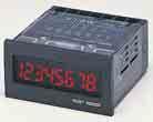
Preset Counter & Timer combined in one body in "G" format FIRST Double display: PV & SV, in "G" format FIRST Serial communication in "G" format FIRST
|
|
|
- Monica Dixon
- 5 years ago
- Views:
Transcription


1 Cat. No.Y103-E1-03


2


3


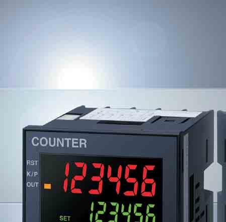
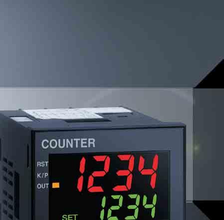
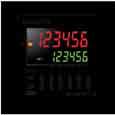
4 Preset Counter & Timer combined in one body in "G" format FIRST Double display: PV & SV, in "G" format FIRST Serial communication in "G" format FIRST The H8GN, with the world's smallest dimensions of mm (1/32-DIN size or " " format), facilitates easier system design and installation and helps enhance performance for downsizing or systemization. An intuitive operability reduces setup time. The H8GN helps pursue a higher productivity on shop floor. Preset Counter/Timer


5 Preset Counter & Timer combined in one body in "G" format FIRST Double display: PV & SV, in "G" format FIRST Serial communication in "G" format FIRST Save the time required to setup for a process. More efficient management through a system integration. Simplified operation. SV-Bank Function Enables presetting up to four set values and changing one to another with a simple operation on a front panel key. This feature helps reduce the setup time required to change between processes. Communications Function Facilitating Data Management The H8GN Series includes a model with serial communications. It can be connected up to 32 devices or computers. RS232C Computer Converter RS485 Simple operation using front panel keys Connection possible with up to 32 devices Help downsizing of control panel, both in footprint and volume. Greater space utilization is also achieved by its versatility. World's Smallest Size for Downsizing of Control Panels A compact and short body of DIN mm Triple in one - features total and preset counter functions as well as timer Switching between preset counter (4 digits) and timer (4 digits) possible. While using the preset counter, it is possible to switch the display to monitor the totalizing count value (8 digits). This feature eliminates the need for more than one device to enable saving space. As a preset counter As a timer As a totalizer 48 Reduced power consumption using backlit negative transmissive LCD. Environment-friendly design without batteries. Fine adjustable control. LED-like LCD Double Display. Programs saved without using batteries Both PV and SV can be viewed on a large, high-visibility negative-transmissive LCD. ON/OFF duty adjustable flicker mode that can be used to perform cyclic control is available for timer operation. This feature allows fine adjustment of control output and saves energy. ON OFF Equipped with ON/OFF-duty Adjustable Flicker Mode Cycle time Set the ON duty rate as a percentage with the up/down keys ON duty
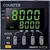
6 Preset Counters Control output is turned ON when the present value has reached the preset value. H8GN H7CX H7BR H7CN H7AN H7S 24 x 48 mm 48 x 48 mm 72 x 72 mm 48 x 48 mm 72 x 72 mm 33 x 10 mm H7GP 24 x 48 mm Totalizing Counters Present value is displayed with no control output. H7HP New H7E H7CN-T H7AN-T 36 x 72 mm 24 x 48 mm 48 x 48 mm 72 x 72 mm Dedicated Counters for Special Applications The following Counters incorporate dedicated control functions for special applications. K3NC H8BM H8PS H8PR 48 x 96 mm 72 x 72 mm 96 x 96 mm 96 x 192 mm Totalizing Counters CSK CSKE
7 Compact preset counter/timer with communications function. General-purpose preset counter with intuitive operation and enhanced visibility. General-purpose counter that is ideal for a wide range of applications including numerical control and quantity control. Compact, simple counter that incorporates the H7AN's main functions. Three-functions in one: timer/preset counter/totalizing counter SV-bank function Backlit negative-transmissive LCD display Five-functions in one: 1-stage/2-stage counter, totalizing counter,batch counter, dual counter, tachometer PV display color change function One-stage preset model Two-stage preset model LED display Preset model Incorporates switches that can be used in combinations for selecting versatile functions according to the application. Counter modules incorporate a BCD I/O function and allow data communications with peripheral devices. One-stage preset model Two-stage preset model Basic Counter Unit Multi-stage Counter Unit LED display Easy-to-see, compact totalizing counter/timer meets IP66G requirements, thus resisting water and oil. Easy-to-see totalizing counter/timer is 36 x 72 mm in size and meets IP66G requirements, thus resisting water and oil. Compact, economical totalizer with high visibility. Easy-to-see, simple totalizing counter. Beige and black body types available Six-digit totalizing counter/time counter Eight-digit totalizing counter Beige and black body types available Backlit LCD Display Time counter Total counter Digital tachometer Beige and black body types available LED display Versatile, easy-to-use totalizing counters. Multi-digit (i.e., 4-, 6-, and 8-digit) models LED display Up/Down Counting Meter Ideal for high-speed operations at 50 khz. Multi-maintenance Counter One Unit works as nine counters or timers and is ideal for machine maintenance control. Cam Positioner Economical counter for angle control allows the use of mechanical cams. Cam Positioner Ideal for 360-degree rotation angle control. LED display Five-stage comparative output model Three-stage preset model BCD output model Communications output model Variety of Compact High-performance Electromagnetic Counters CSK and CSKE models are not listed in the Selection Guide. Refer to individual datasheets.
8 CONTENTS Selection Guide Glossary Technical Information Accessories Discontinued Models History of OMRON Counter
9 Selection Guide Classification Self-powered Total Counter Self-powered Time Self-powered Tachometer PCB-mounting Counter Counter Model New H7EC New H7ET New H7ER New Appearance Beige Black 48.5 Beige Black 48.5 Beige Black Counting mode Supply voltage Number of digits displayed Display Counting speed Note Up type Up type Up type Up type Backlight model: 24 VDC (only for backlight) No-backlight model: Selfpowered Refer to the relevant datasheet. Backlight model: 24 VDC (only for backlight) No-backlight model: Selfpowered Backlight model: 24 VDC (only for backlight) No-backlight model: Selfpowered 3 VDC or 5 7 or 8 7-segment, LCD with or without backlight PNP/NPN universal DC voltage input and no-voltage input: 30 Hz or 1 khz (switchable) AC/DC multi-voltage input: 20 Hz 7-segment, LCD with or without backlight Time range h to h/ 0.0 h to 3999 d 23.9 h or 0 s to 999 h 59 m 59 s/ 0.0 m to 9999 h 59.9 m Control input No-voltage input, voltage input (PNP/NPN universal DC voltage input, AC/DC multivoltage input) Reset system External (reset time: 0.02 s) and manual reset Power consumption Control output Power source for external supply Terminal connection method EMC standards Weight Safety standards Approx. 0.3 W (backlight model) 7-segment, LCD with or without backlight khz with the 4-digit model 10 khz with the 5-digit model No-voltage input, voltage input (PNP/NPN universal DC voltage input, AC/DC multi-voltage input) External (reset time: 0.02 s) and manual reset Approx. 0.3 W (backlight model) No-voltage input, voltage input (PNP/NPN universal DC voltage input) 7-segment, LCD 30 Hz or 1 khz No-voltage input --- External (reset time: 0.02 s), Power-OFF (0.5 s) Approx. 0.3 W (backlight model) Screw, optional wire-wrap Screw, optional Wire-wrap Screw, optional wire-wrap Direct mounting on PC Board or mounting on 28-pin socket Conforms to EN61326 Conforms to EN61326 Conforms to EN61326 Conforms to EN61326 Backlight model: Approx. 65 g No-backlight model: Approx. 60 g UL, CSA, LR, conforms to EN , conforms to VDE0106/P100, CE marking Backlight model: Approx. 65 g No-backlight model: Approx. 60 g UL, CSA, LR, conforms to EN , conforms to VDE0106/P100, CE marking Backlight model: Approx. 65 g No-backlight model: Approx. 60 g UL, CSA, LR, conforms to EN , conforms to VDE0106/P100, CE marking Cat. No. M064 M064 M064 M Approx. 20 g UL, CSA, CE marking 2

, 12 to 24 VDC Refer to the relevant datasheet.")
, 24 VAC (50/60 Hz) /12 to 24 VDC, 12 to 24 VDC 7-segment, negative transmissive LCD with backlight 4 or 6 7-segment, negative")
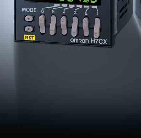
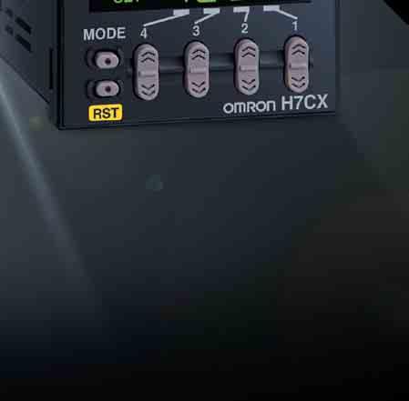
10 Selection Guide Classification Total Counter/Time Counter (DIN 48 x 24) Total Counter/Time Counter (DIN 72 x 36) Preset Counter/Timer Model H7GP H7HP H8GN H7CX Appearance Black Black Beige Black 80 Beige Black Preset Counter/Tachometer Counting mode Supply voltage Number of digits displayed Display Counting speed Note Up type Reversible type Up/Down/Reversible type Up/Down/Reversible type 100 to 240 VAC (50/60 Hz), 12 to 24 VDC Refer to the relevant datasheet. 100 to 240 VAC (50/60 Hz), 12 to 24 VDC 6 6 or 8 PV: 4 digits SV: 4 digits When total count value is displayed: 8 digits 7-segment, negative transmissive LCD with red backlight 7-segment, negative transmissive LCD with red backlight 24 VDC 100 to 240 VAC (50/60 Hz), 24 VAC (50/60 Hz) /12 to 24 VDC, 12 to 24 VDC 7-segment, negative transmissive LCD with backlight 4 or 6 7-segment, negative transmissive LCD with backlight 30 Hz/5 khz 30 Hz/5 khz 30 Hz/5 khz 30 Hz/5 khz, 30 Hz/10 khz for tachometer Time range 0.1 to h/ 1 s to 99 h 59 m 59 s Control input Reset system Power consumption Control output Power source for external supply Terminal connection method EMC standards No-voltage input or DC voltage input (switchable) External and manual resets Reset time: 0.02 s (time counter), 0.02 s or s (total counter) Approx. 6.5 VA Approx. 0.6 W 0.1 to h/ 1 s to 99 h 59 m 59 s No-voltage input or DC voltage input (switchable) External and manual resets Reset time: 0.02 s (time counter), 0.02 s or s (total counter) Approx. 6.5 VA Approx. 0.6 W s to 9999 h --- No-voltage input External (reset time: s, 0.02 s selectable), power-off (0.5 s), and manual Contact output: SPDT 3 A at 250 VAC/30 VDC, resistive load (cosφ=1) No-voltage input or DC voltage input (switchable) External (reset time: s, 0.02 s selectable), manual, and automatic resets. 1.5 W max. Approx. 9.2 VA (at 264 VAC), Approx. 3.7 W (at 12 VDC) Contact output: 3 A at 250 VAC/30 VDC, resistive load (cosφ=1) Transistor output: NPN open collector: 100 ma at 30 VDC max.; residual voltage: 1.5 VDC max. 50 ma at 12 VDC 50 ma at 12 VDC ma at 12 VDC Screw Screw Screw Screw Socket (P2CF, P3G) Conforms to EN61326 Conforms to EN61326 Conforms to EN61326 Conforms to EN61326 Weight Approx. 76 g Approx. 106 g Approx. 80 g Approx. 140 g Safety standards UL, CSA, conforms to EN , CE marking UL, CSA, conforms to EN , CE marking UL, CSA, LR, conforms to EN , conforms to VDE0106/P100, CE marking Cat. No. M049 M049 M065 M070 UL, CSA, conforms to EN , conforms to VDE0106/P100, CE marking 3

, 12 to 48 VDC 7-segment, LEDs Indicator:")

11 Selection Guide Classification Preset Counter Model H7BR H7AN H7CN Appearance Types with backup power supply function for memory protection also available 48 Types with backup power supply function for memory protection also available Counting mode Supply voltage Number of digits displayed Up/Down/Reversible type Up/Down/Reversible type Up/Down/Reversible type 100 to 240 VAC (50/60 Hz), 24 VAC/12 to 24 VDC 100 to 240 VAC (50/60 Hz), 12 to 24 VDC 6 2, 4, 6, or 8 4 Display 7-segment, LCD with backlight 7-segment, LEDs Indicators: Count-in and count-up indicators Counting speed 100 to 240 VAC (50/60 Hz), 12 to 48 VDC 7-segment, LEDs Indicator: Count-up indicator 30Hz/1 khz/5 khz/10 khz 30 Hz/3 khz/5 khz Contact input and solid-state input: 30 Hz Solid-state input: 5 khz Control input No-voltage input, DC voltage input DC voltage input No-voltage input Reset system Power consumption Control output Power source for external supply Terminal connection method EMC standards External (reset time s, 0.02 s selectable), manual, and automatic resets Approx. 10 VA (at 50 Hz, 240 VAC) Approx. 6 W (at 24 VDC) Contact: 3 A at 250 VAC, resistive load (cosφ =1); Transistor output: Open collector: 100 ma max. at 30 VDC max,; residual voltage: 2 VDC max. 160 ma at 12 VDC ±10%; 80 ma at 24 VDC ±10% External (reset time: 0.02 s), Power- OFF (0.5 s), manual, and automatic resets Approx. 10 VA (at 240 VAC, 50 Hz) Approx. 5 W (at 24 VDC) Contact output: SPDT (DPST-NO for double-preset counter) 250 VAC 3 A cosφ = 1 (resistive load) Solid-state output: Open collector 30 VDC max. 100 ma max. (Both outputs can be produced simultaneously.) 80 ma at 12 VDC ±10% --- External (reset time: 0.02 s), Power- OFF (0.5 s), manual, and automatic resets Approx. 12 VA (at 240 VAC 50 Hz) Approx. 2.5 W (at 48 VDC) Contact output: SPDT 250 VAC 3 A cosφ = 1 (resistive load) Solid-state output: Open collector 30 VDC max. 100 ma max. Screw Screw Socket (P2CF, P3G) Conforms to EN Weight Approx. 270 g Approx. 360 g Approx. 150 g Safety standards UL, CSA, conforms to EN , CE marking UL, CSA UL, CSA Cat. No. M009 M001 M004 Note Refer to the relevant datasheet. 4
 100 to 240 VAC (50/60 Hz); 12 to 24 VDC 6 3 (0 to 359 ) 3 (0 to 359 ) 5")
 Control input DC voltage input Accepts input from a special absolute encoder Reset system External (reset time: 0.")
12 Selection Guide Classification Multi-maintenance Counter Cam Positioner Up/Down Counting Meter Model H8BM H8PS H8PR K3NC Appearance Counting mode Supply voltage Number of digits displayed Display Counting speed Up type Up/Down type 24 VDC 24 VDC 100 to 240 VAC (50/60 Hz) 100 to 240 VAC (50/60 Hz); 12 to 24 VDC 6 3 (0 to 359 ) 3 (0 to 359 ) 5 7-segment, LCD with backlight 7-segment, LCD with backlight 7-segment, LEDs 7-segment, LEDs 30 Hz 330 min 1 {rpm} 833 min 1 {rpm} Non-voltage contact (30 Hz max.) Control input DC voltage input Accepts input from a special absolute encoder Reset system External (reset time: 0.1 s) and manual resets Power consumption Control output Power source for external supply Terminal connection method EMC standards Accepts input from a special absolute encoder No-voltage input External reset (reset time: s max.) Approx. 1.8 W (at 24 VDC) Approx. 4 W Approx. 10 W (at 240 VAC, 50 Hz) Open-collector output: 30 VDC max. 100 ma max. Solid-state output: Open collector 30 VDC max. 100 ma max. Solid-state output: Open collector 30 VDC max. 100 ma max. 15 VA max. (max. AC load with all indicators lit) 10 W max. (max. DC load with all indicators lit) Contact: 5 A at 250 VAC/5 A at 30 VDC, resistive load (cosφ = 1); 1.5 A at 250 VAC/ 1.5 A at 30 VDC, inductive load (cosφ =0.4, L/R=7 ms) Min. applicable load; 10 ma at 5 VDC Transistor output: 12 to 24 VDC +10% / 15%, 50 ma max. --- (To rotary encoder) (To rotary encoder) 80 ma at 12 VDC±10% Screw Screw Screw Screw --- Conforms to EN61326 Conforms to EN61326 Conforms to EN61326 Weight Approx. 290 g Approx. 300 g Approx. 1.3 kg Approx. 400 g Safety standards UL, CSA UL, CSA, CE marking UL, CSA, conforms to EN , CE marking Cat. No. M042 M041 M040 N089 UL, CSA, conforms to EN , CE marking Note Refer to the relevant datasheet. 5
13 Glossary Addition-type (Up/Incrementing) counter A counter having an add input and thus capable of counting in an ascending order. Add input Count value Ambient temperature (operating) The ambient temperature at which a device can be used in the continuously operated state. Ambient temperature (storage) The ambient temperature at which a device without power applied, may be stored safely. Automatic reset To automatically return the counter to the 0 state after the lapse of a given time. Counting capacity The maximum value up to which the counter can count. The counting capacity is usually expressed in decimal digits. Count-up The point in time or the state in which the output section of the counter operates when the number of counts reaches the preset value. Dielectric strength The maximum voltage a dielectric can withstand without being damaged. Electromagnetic reset To electromagnetically reset the counter by applying a reset signal. Electromagnetic counter A counter which performs counting by energizing or de-energizing the built-in electromagnet. Electronic counter A counter which mainly consists of transistors, ICs, micro-computers, etc. Electrical life expectancy The life expectancy of a counter when the control output is operated to switch a specified voltage/current load connected to the control output. External reset To reset the counter by a required signal applied from an external source to the reset input signal terminals of the counter. Holding output The control output of the counter without a self-resetting function. The output is continuously held as long as the counter is not reset by the power, external, manual, or electromagnetic reset. Humidity The ambient humidity at which a device can be used for continuous operation. Insulation resistance The resistance offered by an insulating material to the flow of current resulting from a DC voltage. Life expectancy (mechanical) The life expectancy of a counter when the control output of the counter is operated without a load. Manual reset To mechanically reset the counter by manual means. Maximum counting speed The maximum counting speed at which the display or output section of the counter operates accurately without miscounting. The maximum counting speed is expressed in units of counts per second (cps). Memory protective function during power failure The function by which the number of counts at the time of a power failure is memorized until power is again applied to the counter. Operating mode Control output patterns or display patterns that appear when counted up to the value set by the preset counter. Examples: N Mode Set value Count value display Count value display: Held Control output: Held C Mode Control output Set value Count value display: Instantaneous reset Count value display Control output: one shot Control output CPU Memory Operating voltage range The allowable fluctuation range of the voltage required to operate a device (e.g. control and signal voltage). One-shot output A counter control output of fixed duration which can be reset by a self-reset. 6
14 Count input Glossary ONOFF ratio The ratio of the ON signal time of a given input signal to the OFF signal time of the same input signal. The maximum counting speed of each counter is determined by a counting input signal with an ON-OFF ratio of 1:1. Power consumption The maximum wattage used by a device within its operating range at the specified temperature and humidity. Depending on the internal power circuit system of the model, both apparent power and active power are indicated for the AC power supply. Refer to the apparent power when designing a transformer. Preset solid-state counter A counter whose control output operates when it counts up to the set value and which employs a semiconductor circuit for the counting element. Set value Count value Stage Number of preset values that correspond with the number of control outputs. Example: Two-stage Counter Set 2 Set 1 Count value Control output 1 Control output 2 Subtraction-type (Down/Decrementing) counter A counter with a subtract input and thus capable of counting in descending order. Count input Control output Reset To restore the counting, display and output sections of the counter, to their initial states. Reversible-type counter A counter with the capability of counting in an ascending or descending order, depending on the up-down inputs. Also called an up-down counter. Addition Subtraction There are several input modes for addition or subtraction. Count value Totalizing counter A counter which indicates the total value of the counting inputs and is not provided with a control output. Vibration resistance (destruction) The threshold of vibration beyond which an abnormality is expected to occur in the appearance or function of a device. Vibration resistance (malfunction) The threshold of shock beyond which a device can be longer operate properly by satisfying the prescribed ratings. Count value Power reset To reset the counter by cutting off the operating supply voltage. Self-reset To reset the counter by a signal generated by internal circuitry. Shock resistance (destruction) The threshold of shock beyond which an abnormality is expected to occur in the appearance or function of a device. Shock resistance (malfunction) The threshold of shock beyond which a device can be longer operate properly according to prescribed ratings. 7
15 Glossary Counting Function Refer to the following timing charts for the input modes of the incremental, decrementing, and up/down (or reversible-type) Counters. Up/Down Up/Down A Command Input Up/Down D Command Input Count Count Up/Down B Individual Input Up/Down E Individual Input Count Count Up/Down C Quadrature Input Up/Down F Quadrature Input Count Count 8
16 Technical Information Inrush Current --- indicates a constant current and therefore the corresponsing values are omitted from the table. All the values are approximate values and shold therefore only be used as a guide. Counters Model Voltage Applied voltage Inrush current Time (see note) (peak value) H7CX-A11/-AW 100 to 240 VAC 264 VAC 5.8 A 0.7 ms H7CX-A11D1/-AWD1 24 VAC/12 to 24 VDC 26.4 VAC 10.4 A 1.2 ms H7CX-AD 12 to 24 VDC 26.4 VAC 6 A 1.2 ms H7BR 100 to 240 VAC 264 VAC 11.3 A 5 ms 24 VAC/12 to 24 VDC 26.4 VAC 10 A 2 ms H7AN 100 to 240 VAC 264 VAC 16 A 1 ms 100 VDC 110 VDC 8 A 2 ms 48 VDC 52.8 VDC 5 A 3 ms 12 to 24 VDC 26.4 VDC 15 A 2 ms H7CN 100 to 240 VAC 264 VAC 700 ma 2 ms 12 to 48 VDC 52.8 VDC 1.5 A 1 ms H7E H8BM 24 VDC 26.4 VDC 2 A 20 ms H72A 200 to 240 VAC to 120 VDC VDC 26.4 VDC 100 ma 3 ms 12 VDC 13.2 VDC 1.5 A 3 ms CSK All models Cam Positioner Model Voltage Applied voltage Inrush current (peak value) Time (see note) H8PS 24 VDC 26.4 VDC 1.1 A 10 ms H8PR 100 to 240 VAC 264 VAC 15 A 1 ms Note The time of the inrush current is measured as shown in the following figure. 100% (Peak value) 30% Inrush current Measurement time Time 9
17 Technical Information Precautions Refer to the precautions for the individual products as well.!caution Products with Built-in Lithium Batteries The H7S, H7BR, H7AN-M, and have built-in batteries. Do not disassemble the products, deform them with pressure, or subject to heat at more than 100 C, otherwise the battery may explode or burn.!caution Products with Replaceable Lithium Batteries The Y92S-20 (for the H7CN(-M)) and the Y92S-36 (for the New H7E) are replaceable lithium batteries. Do not short the positive and negative poles, recharge or disassemble, or dispose in a fire, otherwise the battery may explode, burn, or leak liquid. Operation Operating Environment When using the Counter, make sure that the ambient temperature and humidity are within the permissible ranges. When storing the Counter, make sure that the storage temperature and humidity are within the permissible ranges. Before supplying power to a Counter that has been kept at a temperature of 10 C or below, leave the Counter at room temperature for at least three hours. Be sure to operate the Counter within its permissible vibration, shock, water, and oil resistance ranges. Do not use the Counter in places with excessive dust, corrosive gas, or direct sunlight. When using the Counter in places with sources of excessive static electricity, such as places with molding materials and powders, and where liquids are being transported, separate the Counter from these sources. Keep away organic solvents, such as paint thinner and benzine, strong alkalis, and strong acids from the Counter, to protect the coverings of the Counter from damage. Do not remove the coverings of the Counter. Input Signal Processing Do not wire the input line of the Counter alongside power lines or high-tension lines in the same conduit. Isolate the input line from power lines or high-tension lines, otherwise the Counter may malfunction due to inductive noise generated from the power lines or high-tension lines. Use shielded wire or metal conduits as much as possible. Keep input signal lines as short as possible. The above points are most important for Electronic Counters operating at high speed. Input line Output Relay Output Model Check that the switching current and voltage are within the rated ranges with the load connected. Make sure that the relay is not overloaded. Otherwise, the relay may not maintain its performance characteristics, such as insulation resistance. Moreover, the relay may burn, receive damage, or cause contact weld or contact failures. The life of a built-in relay greatly varies with the switching condition. Before use, conduct an appropriate life test on some samples of the relay under actual switching conditions and make sure that the relay has no performance problem. If a deteriorated output relay is used continuously, the built-in relay may burn or cause circuit dielectric breakdowns. Do not use the Counter in places with explosive or flammable gas, otherwise the switching arc or heat radiation of the relay may result in a fire or explosion. Solid-state Output Model Check that the output current is within the rated range with the load connected. Damage to the output element may result in a short- or open-circuit malfunction. If a DC inductive load is used, be sure to connect a diode or suppress the counter-electromotive voltage, otherwise the output element may be damaged and result in a short- or open-circuit malfunction. Connection Input Consider the residual voltage of the input sensor and make sure that the input conditions of the Counter conform with the rated conditions. Connection Example with Photoelectric Sensor: E3X-A11 Note Light in dicator (red) Stability indicator (green) Photoelectric sensor main circuit Red (brown) Load White (black) 100 ma max. Black (blue) 30 to 10 VDC The residual voltage is the voltage between the output and 0-V lines when the transistor is ON (i.e., the total voltage between both edges of the transistor and diode bridge). Sensor Separate wiring Counter Power line Residual voltage (V) Load current (ma) 10
 **Output with T1 connected. Red (brown) White (black)* Output** Load Black (blue) Load 0 V 4.")


18 Technical Information Connection Example with Proximity Switch: Proximity switch main circuit Connection Example with Programmable Controller: C200H-OD411/OD211/OD213/OD212 Internal circuit 100 Ω 4.7 kω 2.2 Ω *200 ma max. (load current) **Output with T1 connected. Red (brown) White (black)* Output** Load Black (blue) Load 0 V 4. Make sure that the ripple rate of the supply voltage is within the permissible range if DC is supplied. 0 V Ripple rate 5. Make sure that the load current of the control output is within the permissible range, otherwise the relay or transistor used for the Counter may be damaged. Mounting Although the Counter can be mounted in any direction, it is recommended that the Counter be mounted horizontally and securely. Surface Mounting When mounting two or more Counters vertically with P2CF Sockets, make a space of approximately 20 mm on the top and bottom of each P2CF Socket so that the hooks of the P2CF Socket can be moved easily. Duct Fuse burnout detector Hook 20 The C200H-OD211 has no fuse burnout detector. The C200H-OD411 or C200H-OD211 has no Zener diode. Power Supply 1. Supply all power instantly to the Counter through a switch or relay. Power supply 2. The Counter requires 50 ms for stable operation after power is supplied if the Counter is other than the H7GP or H7HP, which requires 250 ms for stable operation after power is supplied. Do not input any signal before the Counter is in stable operation. Flush Mounting To mount the Counter to a panel with the Y92F-30 Flush-mounting Bracket, insert the front part of the Counter into the square hole of the panel, attach the Y92F-30 to the rear end of the Counter, and press the Y92F-30 towards the panel and reduce the space between the panel and Y92F-30 as much as possible. Then secure the Y92F-30 with the screw of the Y92F-30. Panel Panel P2CF-08 P3G-08 Power supply Counting instable Counting instable 3. Make sure that the fluctuation of the supply voltage is within the permissible range. Screw Y92F-30 Fluctuation of supply voltage 11


19 Technical Information To mount two or more Counters vertically side by side with Y92F- 30 Flush-mounting Brackets, locate the Y92F-30 Flush-mounting Brackets so that the molded springs of each Y92F-30 are located on the left and right of the Y92F-30. Molded spring To mount two or more Counters horizontally side by side with Y92F-30 Flush-mounting Brackets, locate the Y92F-30 Flushmounting Brackets so that the molded springs of each Y92F-30 are located on the top and bottom of the Y92F-30. The impulse voltage test of the power terminals is carried out in conformity with the Japanese JEC-210 standards before shipping. Use a surge absorber, AC MP, or oil capacitor that has a capacity of 0.1 to 1 µf if there is an impulse voltage outside a range from 1.2 x 50 to 1.2 x 50 µs. The Counter reads input signals anytime. The Counter can be set so that it will read input signals when it is reset if it is the H7AN-R@. Be aware that the Counter will have an output signal if the data input change coincides with Counter input. Do not tighten any terminal screw excessively. Counter-electromotive voltage is generated by any inductive load that is turned on or off. For the purpose of surge absorption, when using the Counter to switch an electromagnetic device, such as a solenoid valve, apply a diode if the electromagnetic device is in DC circuitry and a surge absorber if the electromagnetic device is in AC circuitry, otherwise Counter damage or malfunctioning may result. Troubleshooting Refer to the following for the troubleshooting of the Counter if the Counter malfunctions or has errors. 1. The following may result if a heavy inductive load, such as a high-capacity motor or solenoid, shares the power line connected to the Counter or is present near the Counter. The Counter may count up or down without any input signal. The power supply circuit of the Counter may be damaged. To prevent this, keep the motor or solenoid away from the Counter or connect a noise filter to the power supply circuit. Molded spring Dismounting To dismount the Y92F-30 Flush-mounting Bracket from the Counter, loosen the screw of the Y92F-30 and move both hooks upwards and downwards respectively. Screw Motor 2. The following may result if a device with contacts generating arcs shares the power line connected to the Counter or is present near the Counter. The Counter may count up or down without any input signal. To prevent this, connect an arc suppressor to the device. Others Refer to the following to carry out dielectric strength, impulse voltage, and insulation resistance tests of the electric circuitry and non-charged metal parts of the Counter that has been mounted to a control panel. 1. Electrically isolate the Counter from the electric circuitry of the control panel by disconnecting the socket or external wires from the Counter. 2. Short-circuit all the terminals of the Counter, which will prevent the internal circuit of the Counter from damage that may be caused by a machine or component in the control panel with poor dielectric strength or insulation resistance. 3. The following may result if the input device has a relay without highly reliable contacts. The Counter may not count up or down when the contacts are activated. 12


. 5.")
20 Technical Information To prevent this, replace the relay with one that has highly reliable contacts. 4. The following may result if the input signal line is excessively long. The power line connected to the Counter may cause the Counter to count up or down. To prevent this, refer to page page 10, Input Signal Processing. The residual voltage may make it impossible for the Counter to check the interval between input signals, thus obstructing the counting operation of the Counter. To prevent this, make the input signal line as short as possible and insert a to 0.1-µF capacitor into the signal line close to the signal input terminal of the Counter. 8. The following may result if the Counter is used in a place with excessive or continuous vibration or shock. Contact chattering may cause sequencing errors. The built-in parts of the Counter may malfunction due to the stress imposed on the built-in parts. To prevent this, reduce the vibration by putting a rubber cushion under the vibration source. Do not mount the Counter directly to the vibration source. Press machine 9. The following may result if the Counter is in high-speed counting operation with relay input signals. The Counter may count more than the actual number of input signals. To prevent this, set the counting speed to 30 Hz (cps). 5. The following may result if the power line is close to a hightension line. The high-tension line may cause the Counter to count up or down. To prevent this, refer to page 10, Input Signal Processing. High-tension line 6. The following may result if the supply voltage is imposed gradually. The Counter may not operate normally or the Counter displays an inaccurate value. To prevent this, supply all power instantly to the Counter through a switch or relay. Input 10.If the proximity or photoelectric sensor used as the input device is turned on or off while supply voltage is imposed on the Counter, excessive pulses may be generated from the input device and input to the Counter. Power supply Contact chattering is counted. Input device (proximity or photoelectric sensor) An input signal may be generated when the input device is turned on or off. Input signal Digital Counter 11.If the count input is a transistor input at a speed of 30 Hz (cps) maximum, setting the maximum counting speed to 30 Hz (cps) will improve the noise immunity of the Counter. 12.The Counter can be reset with a reset signal, which must be 20 ms long minimum, from the relay or transistor regardless of the maximum counting speed or input method of the Counter. Slidac 7. The following may result if the Counter is used for a long time in a place with excessive dust, direct sunlight, or sprayed water or oil that affects the Counter. The Counter may not count up properly or operate normally and the coverings of the Counter is deformed. To prevent this, protect the Counter from water, oil, dust, and sunlight. A hard front cover will protect the Counter from dust and drops of water. Reset input * The reset signal with distorted waves or chattering waves is acceptable as long as the reset signal is stable for 20 ms minimum. ** The CP1 and CP2 can be input if it passes 50 ms after the reset signal input is completed. 13

21 Technical Information 13.The maximum counting speed is the response speed of the Counter when signals with the minimum permissible signal width are input at an ON-to-OFF ratio of 1:1. If the ratio is not 1:1, the minimum signal width must be higher than the combined specified value for the ON width and OFF width. The response speed will thus be lower. If the width of each signal or interval between adjacent signals is less than the minimum permissible signal width, the Counter will not respond even for an input signal that is less than the maximum counting speed. Ta Tb Ta (ON width) and Tb (OFF width) must be more than the minimum permissible signal width. 30 cps: 16.7 ms; 1 kps: 0.5 ms The maximum counting speed is 1/2 of the rated value if the on-tooff ratio is 1:3. The Counter does not respond because Ta is less than the minimum permissible signal width. 14.If transistor input signals are other than square-wave signals, such as sine-wave, triangular-pulse, or saw-toothpulse signals, all the ON and OFF widths or H- and L-level periods must be more than the minimum permissible signal width. OFF width or H level ON width or L level Ta must be the same as or more than the minimum permissible signal width and so must Tb. OFF width or H level ON width or L level Ta must be the same as or more than the minimum permissible signal width and so must Tb. 14
22 Technical Information Enclosure Ratings IP Protection Specification Code (International Protection) (IEC529) 1. IEC Standards (IEC 529) Protection Against Solid Foreign Objects Grade Protection Criteria 0 No protection 1 Full penetration of 50-mm diameter of sphere not allowed. Contact with hazardous parts not permitted. 50 dia. mm 2 Full penetration of 12.5-mm diameter of sphere not allowed. The jointed test linger shall have adequate clearance from hazardous parts dia. mm 3 The access probe of 2.5-mm diameter shall not penetrate. 2.5 mm 4 The access probe of 1.0-mm diameter shall not penetrate. 1 mm 5 Limited ingress of dust permitted (no harmful deposit). Dust protected 6 Totally protected against ingress of dust. Dust-tight 15
23 Technical Information 2. IEC Standards Protection Against Harmful Ingress of Water Grade Protection Criteria Examination method 0 No particular protection No protection No test 1 Rain Protected against vertically falling drops of water. Spray water downwards invertical direction for 10 minutes using a water-dripping test device. 200 mm 2 Rain Protected against vertically falling drops of water with enclosure tilted 15 from the vertical. Tilt by 15 and spray water for 10 minutes (2.5 minutes in each direction) using a water-dripping test device. 200 mm 3 Rain Protected against sprays to 60 from the vertical. Spray water up to 60 in both directions from the vertical axis for 10 minutes using the test device shown below. 4 Water splash from all directions Protected against water splashed from all directions; limited ingress permitted. Flow per water spray hole: 0.07 l/min Spray water from all directions for 10 minutes using the test device shown below. Flow per water spray hole: 0.07 l/min 5 Housing jets from all directions Protected against lowpressure jets of water from all directions; limited ingress permitted. Spray water from all directions for one minute per m 2 of external surface area and for a total time of no less than 3 minutes using the test device shown below. 2.5 to 3 m 12.5 l/min 6 Strong hosing jets from all directions Protected against strong jets of water, e.g. for use on ship decks; limited ingress permitted. Discharging nozzle dia.: 6.3 Spray water from all directions for one minute per m 2 of external surface area and for a total time of no less than 3 minutes using the test device shown below. 2.5 to 3 m 100 l/min 7 Temporary immersion (see note 1) Protected against the effects of immersion between 15 cm and 1 m. Discharging nozzle dia.: 12.5 Submerge for 30 minutes at the depth of 1 m (if the device is located lower than 850 mm). 8 Continuous immersion (see note 2) Protected against long periods of immersion under pressure. Test according to the conditions agreed upon between the manufacturer and user. 16
24 Technical Information 3. JEM (Japan Electrical Manufacturers Association Standards) Standards (JEM 1030) Protection Against Oil Grade Protection Criteria Criteria F Oilproof Protected against improper operation due to oil drops or spray from any direction. G Oil resistant Protected against penetration of oil drops or spray from any direction. NEMA (National Electrical Manufactures Association) Conversion from NEMA to IEC529 (Reverse conversion is not possible.) No penetration of oil to the extent of interfering with proper operation after dropping the specified cutting oil on a test device for 48 hours at a rate of 0.5 l per hour. No penetration of oil after dropping the specified cutting oil on a test device for 48 hours at a rate of 0.5 l per hour R 3S Note NEMA250 IEC529 NEMA250 IEC529 IP10 IP11 IP54 IP14 IP54 4, 4X 5 6, 6P 12, 12K 13 Based on the Appendix A of the NEMA Standard. Classification of the NEMA enclosure rating differs from that of the IEC529 in corrosion resistance, rust resistance, and watertightness. IP56 IP52 IP67 IP52 IP54 17


 Conforming to VDE0106/P100 P2CF-11 P2CF-11-E (Finger Safe")

25 Accesories (Order Separately) Sockets Model Type Number Applicable Sockets of pins Front Back H7CX 11 P3GA-11 H7CN 11 P3GA-11 Other H7CN 8 P2CF-08-@ P3G-08 H72A P2CF-11-@ P3GA-11 Front-connecting Sockets P2CF-08 P2CF-08-E (Finger Safe Terminal Type) Conforming to VDE0106/P100 P2CF-11 P2CF-11-E (Finger Safe Terminal Type) Conforming to VDE0106/P100 Back-connecting Sockets P3G-08 P3GA-11 Finger Safe Terminal Cover Y92A-48G (Attachment for P3G-08/P3GA-11 Socket) 18


 Applicable Counters H8PS, H7BR, H8BM, H7AN,")
26 Accesories (Order Separately) Hold-down Clips For Rectangular Sockets PYC-A1 PHC-12 PTC-1 Y92H-3 Y92H-4 Mounting Accessories Support Track PFP-100N PFP-50N End Plate PFP-M Support Track PFP-100N2 Spacer PFP-S Watertight Covers Model Y92A-96N Y92A-72N Y92A-49N Y92A-48N Size 96 x 96 mm 72 x 72 mm 48 x 96 mm 48 x 48 mm Enclosure ratings IP66 or NEMA4 (indoors) Applicable Counters H8PS, H7BR, H8BM, H7AN, H7CN Y92A-@@N 19
27 Discontinued Models Production is constantly being re-organized to deal with different models that can be used for the same applications, and models that have not been ordered for some time due to changing needs. Models for which production has been discontinued and their recommended alternative models are listed in the table below. Note Before using recommended alternative models, confirm specifications and other items with the relevant documentation. Name Model Recommended alternative models Scheduled to be discontinued Remarks Miniature Counter AK H7CX End of March 1996 DC input signals are used instead of AC input signals. Therefore, a relay-employed sequential circuit is required. The mounting and external dimensions are different. Electromagnetic CS Not available End of March Counter Electronic Counter H7CL H7CX End of March 2004 The wiring and operating method are different. H7CR H7CX End of March Electronic Counter/Timer Solid-state Unit Counter H8CA-S H7CX End of March 2004 The dimensions, wiring, operating characteristics, and operating method are different. H7S Not available End of March
28 :Production discontinued (as of March 2003) Note: Some of products are not released overseas.
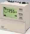
Weekly Time Switch. Rated time Time setting range Time division 24 hrs x 7 days 00:00 to 23:59 1min
 Weekly Time Switch Easy Programming with Large LCD Display and Interactive Functions Programming for 24 hrs x 7 days using just five switches. Sixteen program steps available. Power supply freely selectable
Multifunction Digital Timer
 Multifunction Digital Timer 72 x72 mm Timer with Easy-to-use Functions Nine output modes accommodate a wide variety of applications. All parameters set by scroll-through menus accessed from the front panel.
Solid-State Digital Timer
 Solid-State Digital Timer 1/16 DIN, Digital-Set Timer with 0.1 Second to 9,990 Hours Range 8 field-selectable operation modes Universal AC/DC supply voltage timers available Operations include ON-delay,
Self--powered Time Counter
 Self--powered Time Counter Subminiature Time Counters With Enhanced Appearance and Features Large display with 8.6 mm (0.338 in) height Available with backlit LCD PNP/NPN DC voltage available Sevendigits,timerange0to
Counters. 1/32 DIN), programmable preset counter/timer with an integrated RS-485 communication port.
, programmable preset counter/timer with an integrated RS-485 communication port.") Counters With over three decades in the counter market, Omron can provide a solution to every measurement process requirement, including total counting, timing, preset counting and specific cam positioning
Counters With over three decades in the counter market, Omron can provide a solution to every measurement process requirement, including total counting, timing, preset counting and specific cam positioning
Ordering Information. Self -P owered Count Totalizer H7EC. Subminiature Total Counters With Improved Appearance and Features
 R Self -P owered Count Totalizer Subminiature Total Counters With Improved Appearance and Features H Large display with 8.6 mm (0.338 in) height H Available with backlit LCD H PNP/NPN DC voltage input
Solution Selection Guide
 Solution Selection Guide 2015-2016 Automation Systems Motion & Drives Sensing Control Components Switching Components Safety Timers & Counters V Contents Selection Guide V-ii Digital Timers H5CX-N Digital
Self-powered Totalizer
 Self-powered Totalizer New H7E Compact Economical Totalizer with High Visibility Available with Backlit LCD Display Large display with 8.6-mm character height. Includes new models with backlight for improved
Weekly Timer. Mounting track 50 cm (1.64 ft) length PFP-50N 1 m (3.28 ft) length PFP-100N
 length PFP-50N 1 m (3.28 ft) length PFP-100N") Weekly Timer 1/4 DIN Size Timer Features Prompted Programming and Large LCD Display 24 hours x 7 days programming using just 5 switches 16 program steps and cycle operation Two independent 15 A control
Weekly Timer 1/4 DIN Size Timer Features Prompted Programming and Large LCD Display 24 hours x 7 days programming using just 5 switches 16 program steps and cycle operation Two independent 15 A control
Self-powered Totalizer New H7E
 Self-powered Totalizer New H7E CSM_H7E_-N_DS_E_7_1 Compact Economical Totalizer with High Visibility Available with Backlit LCD Display Large display with 8.6-mm character height. Includes new models with
Ordering Information. Absolute 60-mm-dia. Rotary Encoder E6F-A. High Accuracy and Durability for Automatic Equipment.
 Absolute 60-mm-dia. Rotary Encoder A High Accuracy and Durability for Automatic Equipment Stronger shaft and greater durability (120 N in the radial direction and 50 N in the thrust direction) than previous
E6CP-A. An Absolute Encoder at About the Same Price as an Incremental Encoder. Ideal for robot limit signals. Low-cost Encoder with Diameter of 50 mm
 Low-cost Encoder with Diameter of 50 mm CSM DS_E An Absolute Encoder at About the Same Price as an Incremental Encoder. Ideal for robot limit signals. High-precision detection of automatic machine timing.
Voltage inputs: High and low signal voltages (count, reset, short, counter No. selection, I/O inhibit) No-contact outputs: RUN, forecast
 No-contact outputs: RUN, forecast") Multi-maintenance Counter/Timer (DIN 72 x 72) CSM DS_E_4_1 Nine Built-in Counters/Timers to Measure Equipment Operating Cycles and Times and Forecast Maintenance Timing Provides up to nine counters or
Multi-maintenance Counter/Timer (DIN 72 x 72) CSM DS_E_4_1 Nine Built-in Counters/Timers to Measure Equipment Operating Cycles and Times and Forecast Maintenance Timing Provides up to nine counters or
Voltage inputs: High and low signal voltages (count, reset, short, counter No. selection, I/O inhibit) No-contact outputs: RUN, forecast
 No-contact outputs: RUN, forecast") Multi-maintenance Counter/Timer (DIN 72 x 72) CSM DS_E_5_4 Nine Built-in Counters/Timers to Measure Equipment Operating Cycles and Times and Forecast Maintenance Timing Provides up to nine counters or
Multi-maintenance Counter/Timer (DIN 72 x 72) CSM DS_E_5_4 Nine Built-in Counters/Timers to Measure Equipment Operating Cycles and Times and Forecast Maintenance Timing Provides up to nine counters or
Ordering Information. Self-Powered Tachometer H7ER. Subminiature Tachometers With Improved Appearance and Features. H Large display with 8.
 R Self-Powered Tachometer Subminiature Tachometers With Improved Appearance and Features H Large display with 8.6 mm (0.338 in) height H Available with backlit LCD H Revolutions displayed up to five digits
Slot-type Photomicrosensor with connector or pre-wired models (Non-modulated) *1. configuration. Dark-ON/Light-ON
 *1. configuration. Dark-ON/Light-ON") Slot-type Photomicrosensor with connector or pre-wired models (Non-modulated) * EE-SX/6 Photomicrosensor with 0- to 00-mA direct switching capacity for built-in application. Series includes models that
Slot-type Photomicrosensor with connector or pre-wired models (Non-modulated) * EE-SX/6 Photomicrosensor with 0- to 00-mA direct switching capacity for built-in application. Series includes models that
Absolute Rotary Encoder E6CP
 Absolute Rotary Encoder Absolute Rotary Encoders with Gray Code Output Gray code output decreases output errors Lightweight plastic housing Used with Omron s H8PS Cam Positioner, this encoder detects the
02/11/2015
 24 x 48 Totalizers CTR24 non-backlit model Part number 87622062 Display : 8-digit LCD, height 8 mm Powered by a lithium battery Counter inputs : solid state (4-30 VDC) or voltage (10 260 VAC) Reset on
K3NX Process Meter OPERATION MANUAL
 Cat.No. N90 E1 1 K3NX Process Meter OPERATION MANUAL K3NX Process Meter Operation Manual Produced January 1998 Notice: OMRON products are manufactured for use according to proper procedures by a qualified
Photoelectric Sensors E3F2
 Photoelectric Sensors E3F2 Threaded Cylindrical Photoelectric Sensors with Built-in Amplifier for Use as an Optical Proximity Switch M18 DIN-sized cylindrical housing Housing materials: plastic, nickel
Type Contact form Model Ag (Au clad) Standard DPDT G6A-274P-ST-US Low-sensitivity DPDT G6A-274P-ST40-US
 Standard DPDT G6A-274P-ST-US Low-sensitivity DPDT G6A-274P-ST40-US") Low Signal Relay G6A Fullly Sealed Relay with High Impulse Withstand High sensitivity can be driven by digital circuits. Low-profile design allows use in 12.70 mm PC board rack. Surge withstand meets FCC
Low Signal Relay G6A Fullly Sealed Relay with High Impulse Withstand High sensitivity can be driven by digital circuits. Low-profile design allows use in 12.70 mm PC board rack. Surge withstand meets FCC
Magnecraft General Purpose Relays 750R Series DPDT and 3DPT, 10 A
 and 3DPT, 10 A UL Listed when used with proper Magnecraft s The 750R series octal base, plug-in relays offer clear or full-feature covers with multiple mounting options and accessories. 750R 750R Full-Feature
User s Manual. LG Industrial Systems G3F AT4A. LG Programmable Logic Controller
 User s Manual LG Programmable Logic Controller G3F AT4A GLOFA G4F AT3A LG Industrial Systems CONTENTS Chapter 1. INTRODUCTION 1.1 Features 1-1 Chapter 2. SYSTEM CONFIGURATION 2.1 Example of System Configuration
1.5mm amplitude at 10 to 55Hz frequency in each X, Y, Z direction for 2 hours 500m/s² (approx. 50G) in each X, Y, Z direction for 3 times
 in each X, Y, Z direction for 3 times") Color Mark Color Mark Feature Outstanding color matching accuracy - RGB light emitting diodes and 12-bit resolution - 2 detection modes (color only / color + intensity) - -step sensitivity adjustment for
Color Mark Color Mark Feature Outstanding color matching accuracy - RGB light emitting diodes and 12-bit resolution - 2 detection modes (color only / color + intensity) - -step sensitivity adjustment for
Soft starter, 66 A, V AC, Us= 24 V DC, with control unit, Frame size N. Function Soft starter for three-phase loads, with control unit
 DATASHEET - S811+N66N3S Delivery program Soft starter, 66 A, 200-600 V AC, Us= 24 V DC, with control unit, Frame size N Part no. S811+N66N3S Catalog No. 168978 Eaton Catalog No. S811PLUSN66N3S EL-Nummer
Magnecraft Power Relays
 Description DPST-NO, 30 A; DPDT, 30 A (NO) / 3 A (NC) Description The series power relays offer a small package size and features Class F insulation for a maximum coil temperature of 55 C (3 F). These
Process Transmitter RMA 422
 Technical Information TI 072R/24/ae Process Transmitter RMA 422 Multi-functional 1-2 channel top hat DIN rail unit with loop power supply, alarm set point monitoring, mathematics function and 1-2 analog
Type Contact form Model PCB SPDT G6E-134P-ST-US G6E-134PL-ST-US. Type Contact form Model
 Low Signal Relay G6E Subminiature 7.87 H x.1 W x 16 L mm (0.31 H x 0.3 W x 0.63 L in). High sensitivity with pick-up coil power of 8 mw. Surge withstand meets FCC Part 68 rule and Telcordia 2.5 kv Specifications.
H8GN. Model Number Structure. Ordering Information. Preset Counter/Timer (48 24) Model Number Legend. List of Models
 Model Number Legend. List of Models") Preset Counter/Timer (48 24) CSM DS_E_3_3 A DIN 48 24 Preset Counter. Compact, Yet Equipped with Communication. Only 48 24 83 mm (W H D) Switch between 4-digit preset counter and 4-digit timer operation.
Preset Counter/Timer (48 24) CSM DS_E_3_3 A DIN 48 24 Preset Counter. Compact, Yet Equipped with Communication. Only 48 24 83 mm (W H D) Switch between 4-digit preset counter and 4-digit timer operation.
Instruction Manual. Universal Flow Controller Model 261 / 261-EC-01
 Universal Flow Controller Model 261 / 261-EC-01 Instruction Manual Type ARS 261-EC 01 Art.-no: 82212264 Table of Contents 1. Safety Instructions 2. Product ID - Dimensions 3. Function Description 4. Installation
Product Data Sheet 4656 EZ
 The engineer's choice 4656 EZ INDEX 1 General... 3 2 Mechanics... 3 2.1 GENERAL... 3 2.2 CONNECTIONS... 4 3 Operating Data... 5 3.1 ELECTRICAL OPERATING DATA... 5 3.2 OPERATING DATA - ELECTRICAL INTERFACE
E8Y. Micropressure Sensor with Easy-to-Read Digital Display. Differential Pressure Sensor. Ordering Information. Sensors
 Differential Sensor Micropressure Sensor with Easy-to-Read Digital Repeat accuracy of ±1% FS (setting resolution: 0.01 kpa), high-precision pressure control available. Compact design (31 mm) saves mounting
2 2 Relay outputs. M DIN W72 H7mm. LE7 Weekly/Yearly timer
 LE7M-2 W72 H72mm, Weekly/Yearly Timer Features Easy to check and change the program setting Customizable weekly or yearly unit time setting and control by user Includes daylight saving time function Built-in
02/11/2015
 DIN Rail Mount 17.5 mm MUS/MUSF 80 AC/DC Part number 84872141 Control relays monitoring their own power supply - MUS : Over/undervoltage control Selectable latching (memory) function - MUSF : Over/undervoltage
Modular Lube Lubrication Systems System Controls
 Model 84501 Program Timer Solid State Designed to control the lubrication cycle frequency of air-operated single-stroke pumps. Timer turns pump on/off at programmed intervals via a 3-way or 4-way air solenoid
Frequency/Rate Meter
 Frequency/Rate Meter High-speed, Intelligent Interface Modules with Seven Operating Modes Convert Single or Dual Input Pulses to Display Values 50-kHz input range and 0.006% accuracy for sophisticated
20 mm Beam Pitch General Purpose Area Sensor. Distance between parts shelf and sensor can be shortened (Enables miniaturization of equipment)
") OTHER SUNX PRODUCTS SERIES 0 mm Beam Pitch General Purpose Area Sensor Diagnosis Self-diagnosis Test input Interference prevention Wide sensing area of 7 m,60 mm with 0 mm beam pitch Refer to p.9l for
OTHER SUNX PRODUCTS SERIES 0 mm Beam Pitch General Purpose Area Sensor Diagnosis Self-diagnosis Test input Interference prevention Wide sensing area of 7 m,60 mm with 0 mm beam pitch Refer to p.9l for
Features. Digital Time Switch H5S. Easier and More Convenient to Use
 Digital Time Switch CSM DS_E_7_1 Easier, More Convenient Time Switches, with New 4-circuit Output and Yearly Models in Addition to 2-circuit Weekly Models Independent Day Keys provide easier operation.
Cat. No. N093-E1-1A. K3NR Frequency/Rate Meter
 Cat. No. N093-E1-1A K3NR Frequency/Rate Meter K3NR Frequency/Rate Meter Operation Manual Revised February 2001 iv Notice: OMRON products are manufactured for use according to proper procedures by a qualified
Cylindrical Photoelectric Sensor CY-100 SERIES
 Cylindrical Photoelectric Sensor CY-00 SERIES Listing (2 m cable length type only) Features Wide product range Shape: Standard type Side view type Connector: 2 m cable length type M2 plug-in connector
Magnecraft General Purpose Relays 782 Power Series SPDT 20 A; DPDT 15 A
 72 Power Series SPDT 20 A; DPDT 15 A UL listed when used with proper Magnecraft sockets The 72 Plug-in Power relays offer clear or full-feature covers with multiple mounting options and accessories. Feature
ALLEN BRADLEY TIMING RELAY
 ALLEN BRADLEY TIMING RELAY Configuration Details Product: 700-HS12BA1 Description: 700-HS General Purpose Square Base Timing Relay, On Delay Timer, 1.0 to 180 seconds, DPDT, 120V AC 50/60Hz CONTROL RELAY
I r A Protection against direct contact Finger and back of hand proof to VDE 0106 Part 100
 DATASHEET - NZMH2-A100 Circuit-breaker, 3p, 100A Part no. NZMH2-A100 Catalog No. 259099 Similar to illustration Delivery program Product range Circuit-breaker Protective function System and cable protection
GC61 Digital Pressure Gauge. Operation Manual
 TY-GC61-009A エ GC61 Digital Pressure Gauge Operation Manual 2016. 3 TY-GC61-009A 1/24 For proper and safe operation GC61 Digital Pressure Gauge is a compact digital pressure gauge which complies with the
PBC series. RoHS. Ready. IEC-Type Contactors & Accessories 9-80 Amp AC-3, Amp AC-1 AC Coils. P&B PBC Series IEC Type Contactors & Accessories
 PBC series IEC-Type Contactors & Accessories 9-80 Amp AC-3, 25-125 Amp AC-1 AC Coils File E38802 (PBC) RoHS Ready Users should thoroughly review the technical data before selecting a product part number.
Digital Time Switch H5S. Features. Easier and More Convenient to Use
 Digital Time Switch H5S Easier, More Convenient Time Switches, with New 4-circuit Output and Yearly Models in Addition to 2-circuit Weekly Models Independent Day Keys provide easier operation. Temporary
C200H-AD002/DA002 Analog I/O Units Operation Guide
 C200H-AD002/DA002 Analog I/O Units Operation Guide Revised September 1995 Notice: OMRON products are manufactured for use according to proper procedures by a qualified operator and only for the purposes
Pressure Sensor. Ordering Information. Mini-Cube Pressure Sensor with Easy-to-Read LED Display
 Sens Mini-Cube Sens with Easy-to-Read LED Display Industry s smallest, lightest l Both analog bar and digital pressure values are displayed Two independent outputs plus one analog output are available
Protective function Systems, cable, selectivity and generator protection. i 2 t constant function: switchable. I r A
 DATASHEET - NZMN3-VE630 Circuit-breaker, 3p, 630A Part no. NZMN3-VE630 Catalog No. 259133 EL-Nummer (Norway) 0004358791 Similar to illustration Delivery program Product range Circuit-breaker Protective
Product Data Sheet 8506 VW-691
 The engineer's choice 8506 VW-691 INDEX 1 General... 3 2 Mechanics... 3 2.1 GENERAL... 3 2.2 CONNECTIONS... 4 3 Operating Data... 5 3.1 ELECTRICAL OPERATING DATA... 5 3.2 OPERATING DATA - ELECTRICAL INTERFACE
TeSys contactors. Model d. Type of contactor LC1- LC1- LC1- LC1- LC1-D115 & D09 D18 D25 D38 D40 D50 D95 LC1-D150 DT20 & DT25 DT32 & DT40
 Characteristics Type of contactor LC- LC- LC- LC- LC-D & D09 D8 D2 D38 D40 D0 D9 LC-D0 DT20 & DT2 DT32 & DT40 Environment Rated insulation voltage (Ui) Conforming to IEC 947-4-, overvoltage category III,
Ordering Information. Absolute 60-mm-dia. Rotary Encoder E6F-A. High Accuracy and Durability for Automatic Equipment
 Absolute 60-mm-dia. Rotary Encoder A. High Accuracy and Durability for Automatic Equipment Stronger shaft and greater durability (120 N in the radial direction and 50 N in the thrust direction) than previous
Climatic proofing Damp heat, constant, to IEC Damp heat, cyclic, to IEC
 Deliveryprogramme Contactorrelay,3N/O+1N/C,AC Partno. DILER-31(230V50HZ,240V60HZ) Articleno. 051768 CatalogNo. XTRM10A31F Product range DILER Mini-contactors Application Contactor relays Description with
Input type NPN/Voltage pulse PNP 240 VAC
 Up/Down Counting Meter An Ideal Interface for High-speed Up/Down Counting and Serial Communications 50-kHz input range for high-speed signal processing. A wide selection of outputs: relay, transistor,
Description Set value in neutral conductor is synchronous with set value Ir of main pole. R.m.s. value measurement and thermal memory CSA 100
 DATASHEET - NZMN3-4-AE400 Circuit-breaker, 4p, 400A Part no. NZMN3-4-AE400 Catalog No. 265891 Similar to illustration EL-Nummer (Norway) 0004358857 Delivery program Product range Circuit-breaker Protective
AF-300 E11 Adjustable Frequency Drive
 AF-300 E11 Adjustable Frequency Drive The AF-300 E11 adjustable frequency drive is GE s new generation of micro drives. GE recognized your need for a high-performance, full-featured compact drive and designed
Product Data Sheet 4656 ZW
 The engineer's choice 4656 ZW INDEX 1 General... 3 2 Mechanics... 3 2.1 GENERAL... 3 2.2 CONNECTIONS... 4 3 Operating Data... 5 3.1 ELECTRICAL OPERATING DATA... 5 3.2 OPERATING DATA - ELECTRICAL INTERFACE
Operating Instructions
 COUNTERS CONTROLLERS ENCODERS Operating Instructions Electronic Preselection Counter Two preselections NE 216 Contents Page 1 Safety indications... 2 2 Get to know your NE 216... 4 2.1 NE216 components...
SCALE & WEIGHT DISPLAYS
 The MICRO SERIES SCALE & WEIGHT DISPLAYS LARGE DIGIT MODELS Mighty-5S DPM MODELS Micro-S & Mighty-1S Mighty-1S Micro-S ELECTRO-NUMERICS, INC. Introduction The Electro-Numerics family of Digital Panel Meters
Photoelectrics Through-beam Type PA18C.T..., DC
 Photoelectrics Through-beam Type, DC Miniature sensor range Range: 20 m (Axial), 16 m (Radial) Sensitivity adjustment by potentiometer Modulated, infrared light 850 nm Supply voltage: to 30 VDC Output:
Series CT7N Bimetallic Overload Relays
 Series CT7N imetallic Overload Relays Choose CT7N overloads in DC applications and when monitoring Variable Frequency Drives Sprecher + Schuh has always paid particular attention to the subject of motor
Weighing Meter. Ordering Information. Highly Functional Weighing Meter with Easy-to-read LED. Base Units
 Weighing Meter Highly Functional Weighing Meter with Easy-to-read LED Easily programmable through the front panel or via RS-232C, RS-485, or RS-422. Programming with easy setup and calibration. Load cell
MASTR II BASE STATION 12/24V POWER SUPPLY 19A149979P1-120 VOLT/60 Hz 19A149979P2-230 VOLT/50 Hz
 Mobile Communications MASTR II BASE STATION 12/24V POWER SUPPLY 19A149979P1-120 VOLT/60 Hz 19A149979P2-230 VOLT/50 Hz CAUTION THESE SERVICING INSTRUCTIONS ARE FOR USE BY QUALI- FIED PERSONNEL ONLY. TO
Type Contact form Model
 Low Signal Relay G6A High sensitivity can be driven by digital circuits. Low-profile design allows use in.70 mm (0.50 in) PC board rack. Surge withstand meets FCC Part 68 regulation. Units can be mounted
GC30 Digital Differential Pressure Gauge Operation Manual
 TY-GC30-001A GC30 Digital Differential Pressure Gauge Operation Manual NAGANO KEIKI CO., LTD 2004.02.12 For safety of use TY-GC30-001A In order to safely and correctly utilize this device, please read
I r A Protection against direct contact Finger and back of hand proof to VDE 0106 Part 100
 DATASHEET - NZMC1-A160 Circuit-breaker, 3p, 160A Part no. NZMC1-A160 Catalog No. 283296 Similar to illustration Delivery program Product range Circuit-breaker Protective function System and cable protection
28 & 32 & 40 & 55 & 65 & 84-INCH TFT-LCD 4K MONITOR
 28 & 32 & 40 & 55 & 65 & 84-INCH TFT-LCD 4K MONITOR INSTRUCTION MANUAL Please read this manual thoroughly before use, and keep it handy for future reference. TABLE OF CONTENTS 1, General information...
HPX-T Series. Auto-tuning Fiber Optic Photoelectric Control. Specifications CLICK FEATURES AMPLIFIER UNIT ORDER GUIDE. No.
 6 HPX-T Series Au-tuning Fiber Optic Phoelectric Control Specifications FEATURES Built-in Au-tuning Aumatically Adjusts Scanning Characteristics. Adjustment Steps, Results and Scanning Conditions Digitally
Model Number Structure
 Cycle Control Units CSM DS_E_7_1 Refer to Safety Precautions for All Power Controllers. Used in Combination with the to Enable High-precision Temperature Control Use cycle control to achieve power control
AP-40. AP-40 Series Features Industry s smallest-sensor head Ultra lightweight High-speed response Two-color LED digital pressure display
 AP-34 Separate Amplifier Type Sensor Series Features Industry s smallest-sensor head Ultra lightweight High-speed response Two-color LED digital pressure display Description Industry's smallest & lightest
Multifunction devices
 devices devices devices, electronic Type Page LED multifunction displays pulse, frequency, time (DC) Codix 524 240 pulse, frequency, time (AC+DC) Codix 544 243 LCD multifunction preset counters 1 or 2
4K LED MONITOR 430LED4K & 550LED4K INSTRUCTION MANUAL. Please read this manual thoroughly before use, and keep it handy for future reference.
 4K LED MONITOR 430LED4K & 550LED4K INSTRUCTION MANUAL Please read this manual thoroughly before use, and keep it handy for future reference. CONTENTS 1. GENERAL INFORMATION...3 2. 3. 1.1. 1.2. 1.3. 2.1.
LC2D09E7 REVERSING CONTACTOR 575VAC 9A IEC
 Product datasheet Characteristics LC2D09E7 REVERSING CONTACTOR 575VAC 9A IEC Price* : 86.25 GBP Main Range Product name Product or component type Device short name Contactor application Utilisation category
Eaton Durant. Counters, process instruments and hour meters.
 Alltid Always tillgänglig available - Alltid öppen! - Always open! Electronic totalizers, LCD display - 1/32 DIN 24x mm Eaton Durant Catalogue Weight Type number kg/each Totalizer, add/subtract, NPN/PNP
Quick-disconnect cables. Adjustable mounting brackets
 MiniSafe File No. LR90200 Operation MiniSafe 1.0 inch (25.4 mm) resolution 100 foot (30.5 m) range Individual Beam Indicator lights covered by U.S. and international patents Compact size 2.25 x 1.8 inches
Installation and User Guide 458/CTR8 8-Channel Ballast Controller Module
 Installation and User Guide 458/CTR8 8-Channel Ballast Controller Module Helvar Data is subject to change without notice. www.helvar.com i Contents Section Page Introduction 1 Installation 2 1. Attach
Process transmitter RMA422
 Technical information TI072R/09/en Mat. No. 51001905 Process transmitter RMA422 Multifunctional 1-2 channel top hat DIN rail unit with intrinsically safe current input and loop power supply, alarm set
MG-XV operating instruction. Measuring of norm signals, 4-8-digit. Panel instrument type MG-BV Construction instrument type MG-AV
 MG-XV operating instruction Measuring of norm signals, 4-8-digit Panel instrument type MG-BV Construction instrument type MG-AV Contents 1. Brief description... 3 2. Safety instructions... 3 2.1. Proper
USER S MANUAL. FX2N-8AD Analog input block
 USER S MANUAL FX2N-8AD Analog input block FX2N-8AD Analog input block Foreword This manual contains text, diagrams and explanations which will guide the reader in the correct installation and operation
SQM40/41 Actuators for air and gas dampers
 SQM40/41 Actuators for air and gas dampers Description SQM40/41 actuators are used for the positioning of flow control valves, butterfly valves, dampers or any application requiring rotary motion. The
7 SegmneDisplay Unit With High Bright Characters (D1SC-N : W32 H57mm, D1SA Series: W11 H22mm)
") SC-N/SA Series 7 Segment Display Unit 7 SegmneDisplay Unit With High Bright Characters (SC-N : W32 H57mm, SA Series: W H22mm) Features Selectable decimal (0 to 9) or hexadecimal (0 to 9, A to F) indication
SC-N/SA Series 7 Segment Display Unit 7 SegmneDisplay Unit With High Bright Characters (SC-N : W32 H57mm, SA Series: W H22mm) Features Selectable decimal (0 to 9) or hexadecimal (0 to 9, A to F) indication
Preset counters, electronic
 LCD preset counters Adding or subtracting (battery) 901 Type 901 is a simple battery powered preset pulse counter with 12... 250 V AC/DC count and reset input. The 6-digit, 2-line LCD display shows the
Ordering details. Approval. Classification
 Datasheet - SRB 301MC-24V Guard door monitors and Safety control modules for Emergency Stop applications / General Purpose safety controllers (Series PROTECT SRB) / SRB 301MC Fit for signal evaluation
Preset Counters. X e. X d 6.92 X. 0. IP khz Batch. LCD Preset Counters 1, 2, 4 or 6 Presets. Multifunction. Fast and user-friendly
 The Codix 923/924 can be used universally. As a preset pulse counter, tachometer or preset timer with up to 6 presets it is able to solve a very wide range of control and monitoring tasks in every application.
Fiber-Optic Sensor Amplifiers E3S-X3, E3X-NL and E3X-NM Discontinued March 2012; Revised Replacements
 NO: PH-165 PRODUCT: E3S-X3, E3X-NL, E3X-NM DATE: August 2012 TYPE: Discontinuation Update Fiber-Optic Sensor Amplifiers E3S-X3, E3X-NL and E3X-NM Discontinued March 2012; Revised Replacements Affected
Datasheet - SRB301LC 24VAC/DC
 25.02.2016-18:05:23h Datasheet - SRB301LC 24VAC/DC Guard door monitors and Safety control modules for Emergency Stop applications / General Purpose safety controllers (Series PROTECT SRB) / SRB301LC Preferred
Type: NZMN1 A100 Article No.: Sales text Circuit breaker3p systems/cable prot. Ordering information Number of poles
 Type: NZMN1 A100 Article No.: 259085 Sales text Circuit breaker3p systems/cable prot. Ordering information Number of poles Description Rated current = rated uninterrupted current Setting range 3 pole I
Model DT-311J. And DT-311J-230V(AC) DIGITAL STROBOSCOPE INSTRUCTION MANUAL
 DIGITAL STROBOSCOPE INSTRUCTION MANUAL") Test Equipment Depot - 800.517.8431-99 Washington Street Melrose, MA 02176 - TestEquipmentDepot.com Model DT-311J And DT-311J-230V(AC) DIGITAL STROBOSCOPE INSTRUCTION MANUAL 1. GENERAL The DT-311J DIGITAL
Test Equipment Depot - 800.517.8431-99 Washington Street Melrose, MA 02176 - TestEquipmentDepot.com Model DT-311J And DT-311J-230V(AC) DIGITAL STROBOSCOPE INSTRUCTION MANUAL 1. GENERAL The DT-311J DIGITAL
Preset counters, electronic
 The multifunction preset counters Codix 923 / 924 can be used universally. These preset pulse counters, tachometers or preset timers with up to 6 presets can solve a wide variety of control and monitoring
Flexible Counter Series in DIN size 24 x 48 mm
 Flexible Counter Series in DIN size 24 x 48 mm high contrast 8-digit LCD display or brilliant 6-digit LED display different supply voltages available: independent of mains supply with lithium battery or
Capacitance Limit Detection nivotester FTC 420/421/422
 Technical Information TI 127F/00/en Capacitance Limit Detection nivotester FTC 420/421/422 Limit switches in Minipac design for liquids and bulk solids Application Nivotester FTC 420...422 capacitive limit
Flexible Counter Series in DIN size 24 x 48 mm
 Flexible Counter Series in DIN size 24 x 48 mm high contrast 8-digit LCD display or brilliant 6-digit LED display different supply voltages available: independent of mains supply with lithium battery or
WIRING. Connection connector. NPN output type Standard type. Main circuit. High-function type. Main circuit. PNP output type.
 INSTRUCTI MANUAL Sensor High-performance Digital Display DP-1 Series Thank you very much for using SUNX products. Please read this Instruction Manual carefully and thoroughly for the correct and optimum
FIELD MOUNTED RATE TOTALISER MODEL 202D
 FIELD MOUNTED RATE TOTALISER MODEL 202D 16 June 2003 Introduction 1 1. INTRODUCTION The Model 202Di Rate Totaliser is a microprocessor based instrument which accepts a frequency or pulse input from
UNIVERSAL DIGITAL METER DC Volts and Amps AC RMS Volts and Amps Thermocouples and RTDs Process Signals Strain Gauge and Load Cell
 99 Washington Street Melrose, MA 02176 Fax 781-665-0780 TestEquipmentDepot.com UNIVERSAL DIGITAL METER DC Volts and Amps AC RMS Volts and Amps Thermocouples and RTDs Process Signals Strain Gauge and Load
Electronic Panel Meters DIGEM Preference Program Process control, automation & laboratory uses Class 0.01 to 1 Current, Voltage, Frequency,
 Electronic Panel Meters DIGEM Preference Program Process control, automation & laboratory uses Class 0.01 to 1 Current, Voltage, Frequency, Temperature, RPM, Pressure, etc. LED/ LCD displays 1999 to 99999
KRF EMC Filters Installation, Operation and Maintenance Manual
 KRF EMC Filters Installation, Operation and Maintenance Manual KRF EMC Filters limit high frequency noise, as well as: Reduce interference Protect sensitive equipment Eliminate drive cross-talk Meet FCC
Solution Selection Guide
 Solution Selection Guide 2015-2016 Automation Systems Motion & Drives Sensing Control Components Switching Components Safety Digital Panel Meters Contents Selection Guide W-ii K3HB -X, -H, -V, -S Process,
OPTOTRONIC Intelligent
 OPTOTRONIC Intelligent Compact constant current LED drivers Dimmable DALI Areas of application _ Installation in emergency lighting systems according to IEC 61347-2-13, appendix J _ Suitable for use in
Description Set value in neutral conductor is synchronous with set value Ir of main pole. CSA 100. conductor. I r A 50-63
 Circuit-breaker,4p,63A Partno. NZMH1-4-A63 Articleno. 284426 Similar to illustration Deliveryprogram Product range Circuit-breaker Protective function System and cable protection Standard/Approval IEC