(12) Patent Application Publication (10) Pub. No.: US 2003/ A1
|
|
|
- Wendy McCoy
- 5 years ago
- Views:
Transcription
1 US A1 (19) United States (12) Patent Application Publication (10) Pub. No.: US 2003/ A1 Edwards et al. (43) Pub. Date: Nov. 20, 2003 (54) USER INTERFACE METHOD AND Publication Classification APPARATUS FOR AMEDICAL DEVICE (51) Int. Cl."... A61N 1/39 (76) Inventors: D. Craig Edwards, Fall City, WA (US); (52) U.S. Cl /5 Kelly J. Locke, Woodinville, WA (US); Mark Gausman, Bellevue, WA (US); (57) ABSTRACT Alex Otman, Bothell, WA (US); Richard C. Kirkland, WA (US); SE R. i.n. E. St s): A user interface method and apparatus is described for use WA (US) Correspondence Address: Steven J. Shumaker SHUMAKER & SIEFFERT, PA. with a defibrillator (100) Such as an automated external defibrillator (AED). The user interface comprises a plurality of layered user interface components which become avail able to the operator of the defibrillator (100) as they become necessary or appropriate during the operation of the defibril 8425 Seasons Parkway lator (100) and treatment of the patient. In one embodiment, Suite 105 the layered user interface components comprise an on/off St. Paul, MN (US) actuator (108), a lid (104), an electrode package (120) containing defibrillation electrodes (142, 144), and a shock (21) Appl. No.: 10/147,241 key (170), as well as accompanying visual and aural instruc tions for operating the defibrillator (100) and for treating the (22) Filed: May 15, 2002 patient.
2 Patent Application Publication Nov. 20, 2003 Sheet 1 of 12 US 2003/ A1 s ce S s
3
4 Patent Application Publication Nov. 20, 2003 Sheet 3 of 12 US 2003/ A1 E. - E
5
6 Patent Application Publication Nov. 20, 2003 Sheet 5 of 12 US 2003/ A1
7 Patent Application Publication Nov. 20, 2003 Sheet 6 of 12 US 2003/ A1 IO) See S 23.2% s S M IN-1NO
8 Patent Application Publication Nov. 20, 2003 Sheet 7 of 12 US 2003/ A1 144
9 Patent Application Publication Nov. 20, 2003 Sheet 8 of 12 US 2003/ A1 A&
10 Patent Application Publication Nov. 20, 2003 Sheet 9 of 12 US 2003/ A1
11
12
13

14 US 2003/ A1 Nov. 20, 2003 USER INTERFACE METHOD AND APPARATUS FOR AMEDICAL DEVICE FIELD OF THE INVENTION The present invention relates generally to a user interface method and apparatus for a medical device, and more particularly to a user interface method and apparatus for a defibrillator. BACKGROUND OF THE INVENTION 0002 Sudden cardiac death is the leading cause of death in the United States. Most Sudden cardiac deaths are caused by ventricular fibrillation, in which the heart's muscle fibers contract without coordination, thereby interrupting normal blood flow into the body. The best known effective treatment for ventricular fibrillation is electrical defibrillation, in which an electrical pulse is applied to the patient's heart. The electrical pulse must be delivered within a short time after onset of ventricular fibrillation in order for the patient to have any reasonable chance of Survival The current trend in the medical industry is to make life-saving portable medical devices, Such as automated external defibrillators (AEDs), more widely accessible so that patients in need can be treated as quickly as possible. AS the availability of portable medical devices continues to increase, more places will have these devices for use in emergency situations, Such as in homes, police cars, work sites, and public gathering places. This increase also comes with the heightened likelihood that these portable medical devices will be used by people without medical training or people who are minimally trained in the handling of the medical devices. At the same time, the benefit of having life-saving medical devices immediately available in many places is not fully realized unless the medical devices can be promptly activated and used quickly in case of emergency. Therefore, a portable medical device, Such as an AED, must be configured Such that even a lay person can intuitively and quickly activate and use the medical device A medical device may automatically instruct an operator how to properly operate the medical device via various user interface components. For example, an AED may include a voice command System, a Screen command System, and/or various graphics Visible to the operator. Additional user interface components may also be available. For example, an AED typically includes a pair of defibril lation electrodes to be applied by an operator on the patient's body. Ideally, various user interface components should be immediately available to the operator of a medical device So that the operator can access or follow instructions offered by the user interface components to operate the medical device to Save the patient's life. At the Same time, Some of the user interface components should be made available to the opera tor at the appropriate points during treatment of the patient in order to ensure that an instructional command, for example a voice prompt, of the medical device can timely guide the operator how to properly operate the device and treat the patient. This feature can be particularly helpful when the medical device is likely to be used by a lay person who is not very familiar with the medical device and thus needs to rely on commands issued by the medical device to properly handle the medical device. SUMMARY OF THE INVENTION In accordance with the present invention, a method and apparatus is disclosed for providing a layered user interface for an operator of a portable medical device, meaning that instructions concerning a Series of operations to be performed by the operator for the treatment of a patient using the medical device, along with user interface tools to perform those operations, are provided to the operator as each of the operations becomes necessary or appropriate for treatment In one aspect of the invention, the medical device is a defibrillator, and a layered user interface is provided that includes an activation layer, an electrode application layer, and a defibrillation pulse delivery layer. The activation layer guides the operator to activate the defibrillator, and may include an on/off button. The electrode application layer is made available to the operator Subsequent to the activation layer, and guides the operator to apply electrodes to the patient. The electrode application layer may include an electrode package containing the electrodes, and instructions concerning opening the package and applying the electrodes to the patient. The defibrillation pulse delivery layer is made available to the operator Subsequent to the electrode appli cation layer, and guides the operator through delivery of a defibrillation pulse to the patient. The defibrillation pulse delivery layer may include a shock key that the operator presses to initiate delivery of the defibrillation pulse, and instructions concerning actuating the Shock key In another aspect of the invention, a method for providing a user interface to an operator of an external defibrillator includes first drawing the attention of the opera tor to an actuator for activating the defibrillator. Upon the defibrillator being activated, an electrode package contain ing defibrillation electrodes is revealed to the operator, along with instructions for deploying the electrode package. Upon the electrode package being deployed, a shock key is revealed to the operator, along with instructions for actuat ing the shock key to initiate delivery of a defibrillation pulse. The various provided instructions may include Visual, audible, written, or diagrammatic instructions In a further aspect of the invention, a method for providing a user interface to an operator of an external defibrillator includes first instructing the operator concern ing activating the defibrillator. Once the defibrillator is activated, the operator is provided with an electrode package having an opener that is actuatable by the operator. The operator is instructed concerning opening the electrode package, and upon the operator opening the electrode pack age, the operator is instructed concerning removal of elec trodes from the electrode package. Upon the operator removing the electrodes from the electrode package, the operator is instructed concerning the positioning of the electrodes on the patient. Upon the operator positioning the electrodes on the patient, the operator is instructed concern ing Subsequent care giving operations. In various aspects of the invention, the Series of instructions provided to the operator includes written information, audible information, or color and diagrams relating to the Successive operations to be performed by the operator of the defibrillator. The operator may also be provided with Status information concerning the positioning of the electrodes on the patient, Such as by providing the operator with Visual Status Signals or with audible instructions prompting the operator to check the positioning of the electrodes.

15 US 2003/ A1 Nov. 20, 2003 BRIEF DESCRIPTION OF THE DRAWINGS The foregoing aspects and many of the attendant advantages of this invention will become more readily appreciated as the Same become better understood by ref erence to the following detailed description, when taken in conjunction with the accompanying drawings, wherein: FIG. 1 is a perspective view of a medical device comprising a defibrillator which incorporates a layered user interface in accordance with the present invention; FIG. 2 is a schematic block diagram of several of the key components of the defibrillator shown in FIG. 1; 0012 FIG. 3 depicts the defibrillator of FIG. 1 wherein a lid of the defibrillator is opened, revealing an electrode package having a handle previously hidden beneath the lid; 0013 FIG. 4 depicts an operator of the defibrillator opening the electrode package by grasping and pulling the handle; FIG. 5 depicts the operator removing defibrillation electrodes from the opened electrode package; 0015 FIG. 6 depicts the defibrillator after the defibrilla tion electrodes have been removed from the electrode pack age, now discarded; 0016 FIG. 7 depicts the operator removing an electrode pad from a liner sheet on which the defibrillation electrodes are removably adhered; 0017 FIG. 8 depicts proper placement of the defibrilla tion electrodes on the exposed chest of a patient; 0018 FIG. 9 depicts the defibrillator shown in FIG. 1 while in use by an operator; 0019) FIG. 10 depicts a fully automatic defibrillator; 0020 FIG. 11 depicts a reference card mounted on a surface portion of the defibrillator lid made visible to the operator when the lid is opened; and 0021 FIG. 12 is a flow diagram depicting a prompting routine executed by the defibrillator to deliver visual and aural instructions to the operator. DETAILED DESCRIPTION OF THE PRESENT INVENTION In accordance with the present invention, a user interface is provided for a portable medical device compris ing a plurality of layered user interface components. The user interface components are layered So as to become available to the operator of the device as they become necessary or appropriate during the operation of the device and treatment of the patient. Stated another way, the user interface components are layered to Successively provide the operator with instructions and implements for operating the device and treating the patient. In the present description, the term user interface component' is used to encompass any message and or/instruction Sent to or received from the operator of the medical device, any device component or accessory used to Send or receive Such messages/instruc tions, and any implement that is physically used by the operator for operation of the device or treatment of the patient FIG. 1 illustrates a medical device embodied as a portable automated external defibrillator (AED) 100, Suit able for incorporating the layered user interface of the present invention. Although a defibrillator is used to describe this embodiment, in light of this disclosure, those skilled in the art will be able to implement the present invention with other types of medical equipment without undue experimentation. Further, in the following description certain Specific details are Set forth in order to provide a thorough understanding of various embodiments of the present invention. One skilled in the art will understand, however, that the present invention may be practiced with out these details. In other instances, well-known functions, features, and operations of AEDS have not been shown or described in detail in order to avoid unnecessarily obscuring the description of the various embodiments of the present invention Returning to FIG. 1, an AED 100 incorporating a layered user interface formed in accordance with the present invention is depicted. AS depicted in the illustrated embodi ment, the user interface components of the layered user interface may comprise an on/off actuator 108, a lid 104, an electrode package 120 (see FIG.3) and a shock key 170 (see FIG. 6), as well as accompanying visual and/or audible instructions for operating the AED and for treating the patient. AS will be appreciated from the following descrip tion, beginning with the on/off actuator 108, each Successive user interface component will become available to the operator as it becomes necessary for use by or instruction to the operator As shown in FIG. 1, the AED 100 includes a housing 102 containing the electronics necessary for the operation of the AED 100, as will be described in more detail below. As shown in more detail in FIG. 2, the AED 100 includes a microprocessor 190 which controls the operation of the AED 100. The microprocessor 190 is connected to an LED display 160, a speaker 152, an on/off actuator 108, and a shock key 170. The microprocessor 190 is also connected to a memory 199 which stores a prompting routine 200 (see FIG. 12) formed in accordance with the present invention to generate Visual instructions upon the display 160 and any accompanying aural instructions transmitted via the Speaker 152. In yet other embodiments of the present invention, the memory Stores a voice recognition Software module which allows the rescuer to operate the AED 100 and respond to Visual and/or aural instructions via Voice command rather than using the Start and Shock buttons. Such a module in combination with a microphone would then provide the rescuer with hands-free operation of the AED During defibrillation operation, the microprocessor 190 analyzes an electrocardiogram (ECG) of a patient using an automatic heart rhythm detection algorithm also Stored in the memory 199 to identify whether the patient is experi encing a shockable heart rhythm, Such as Ventricular fibril lation. The detection algorithm executed by the micropro cessor 190 in the actual embodiment of the present invention described herein is similar to that used in the LIFEPAKOE 500 defibrillator provided by Medtronic Physio-Control Corp. of Redmond, Wash. Other known heart rhythm detec tion algorithms may also be used without departing from the Scope of the present invention, Such as those algorithms designed to comply with Standards promulgated by the ASSociation for the Advancement of Medical Instruments

16 US 2003/ A1 Nov. 20, 2003 (AAMI). The ECG signals analyzed by the detection algo rithm are collected by defibrillation electrodes 142,144 and passed through a monitor circuit 194 to an analog-to-digital converter 192. The analog-to-digital converter 192 then passes the digitized signals to the microprocessor 190. If the microprocessor 190 detects a shockable rhythm, the micro processor causes a charge circuit 196 to generate a current causing a storage capacitor (not shown) to charge in prepa ration for delivery of a defibrillation pulse. When the capaci tor is fully charged, and delivery of the defibrillation pulse initiated, a discharge circuit 198 coupled to the micropro cessor 190 and charge circuit 196 discharges the defibrilla tion pulse to the defibrillation electrodes 142, 144 for application of the defibrillation pulse to the patient Returning to FIG. 1, the AED housing 102 includes an on/off actuator 108 which is sized and colored so as to attract the operator's attention as the first action required to use the AED 100. For example, in one embodi ment, the on/off actuator 108 is large in size (relative to its required mechanical function) and colored bright yellow to Visually contrast with the Substantially gray/black colored lid 104 of the AED 100. Though the on/off actuator 108 is illustrated to be in the form a button, the actuator may take various other shapes and forms, for example, a membrane, plate, bar, etc., as long as it is adapted to receive an operator's instruction to activate the AED 100. In one embodiment, the on/off actuator 108 is configured so that depressing it sequentially activates the AED 100 and opens the next user interface component, i.e., a lid 104. The lid 104 is pivotally coupled to the housing 102 at two pivot points 106 in a conventional manner, so that the lid 104 can be opened as shown in FIG. 3. Alternatively, movement of the lid 104 to an open position can be the event activating the AED 100. Indeed, one skilled in the art will appreciate that the presence of the on/off actuator 108 is optional, and the AED 100 could instead be activated by the operator opening the lid 104, or by another operator-initiated action. Such Single-action methods and Systems for activating medical devices are described in more detail in U.S. application Ser. No., filed May 6, 2002, entitled Single-Action Method of Activating and Exposing User Interface of Medi cal Device, and Specifically incorporated herein by refer ence. Activation of the medical device by any of these or other methods or Systems may be referred to in the context of the present invention as an activation layer of the layered user interface FIG.3 illustrates the AED 100 of FIG. 1 when the lid 104 is opened, bringing the operator to the next layer of user interface component that is appropriate for use at this point in the operation of the device and the treatment of the patient, i.e., opening the lid 104 brings the operator to an electrode package 120 positioned within the housing 102 beneath the lid 104. In one embodiment, the electrode package 120 is a bag attached to the housing 102 by an anchor pin 122. Contained within the electrode package 120 are a pair of defibrillation electrodes (not shown in FIG. 3) that are electrically coupled with monitoring and defibrilla tion circuitry inside the housing 102 by an electrode con nector 124 and electrode wires As will be appreciated by those skilled in the defibrillator arts, once an AED is activated, the next Step in its operation is typically to apply a pair of defibrillation electrodes to the patient's chest that are used to monitor the patient s heart rhythm and deliver a defibrillation pulse is necessary. Accordingly, in one embodiment of the present invention, the electrode package 120 is positioned beneath the lid 104 and sized so as to attract the operator's immediate attention as the next appropriate action to take in the operation of the device and treatment of the patient. To further intuitively guide the operator in the correct operation and application of the electrodes, the electrode package 120 includes a package opening member, Such as handle 128, which the operator pulls to open the electrode package along a tear line 130 and release the defibrillation electrodes packaged therein. To further bring attention to the handle, the handle is configured and colored to be conspicuous to the operator. For example, in one embodiment the handle 128 is large in size (relative to its required mechanical function) and colored bright red to visually contrast with the substan tially white colored electrode package 120. Also, the handle has a skew orientation-i.e., not aligned parallel with the Sides of the Substantially rectangular electrode package 120 which further visually attracts the operator's attention. Still further, the handle 128 itself may include diagrammatic arrows 134 indicating the direction the operator should pull the handle and the upper Surface of the electrode package 120 may include a graphical diagram 132 depicting how the operator should grasp and pull the handle 128 in order to open the electrode package 120 (as well as a patient diagram 136 that depicts the appropriate placement of the defibril lation electrodes on the chest of a patient) In addition to the size, configuration, color and placement of the electrode package 120 and the handle 128, the AED 100 may issue audible instructions to the operator upon opening of the lid 104 to pull the handle 128 to open the electrode package 120, as well as audible instructions to first call for help and remove clothing from the patient's chest. It will be appreciated by those skilled in the art that although highly desirable, Such audible instructions may be omitted without departing from the Spirit and Scope of the present invention FIG. 4 depicts the operator pulling on the handle 128 in order to open the electrode package 120 along the tear line 130. FIG. 5 then shows the operator removing the defibrillation electrodes 142, 144 (also commonly referred to as electrode pads) from the electrode package 120. Referring now to FIG. 6, the AED 100 is shown after the defibrillation electrodes 142, 144 have been removed from the opened electrode package 120 (which the operator has discarded or otherwise set aside, and is not shown in FIG. 6). The operator is now presented with the next layer of user interface component, namely, the defibrillation electrodes 142, 144 themselves. In the embodiment shown in FIG. 7, the defibrillation electrodes 142, 144 are positioned on a Single pad liner 146 of contrasting color to that of the electrodes. (Those skilled in the art will appreciate that the defibrillation electrodes could instead be positioned on Sepa rate liners or in other Suitable configurations.) For example, the defibrillation electrodes 142 and 144 may have respec tively colored boundaries of yellow and red, with the liner 146 being blue-colored plastic. It has been found that lay persons unfamiliar with the use of AEDs or medical devices often do not realize that defibrillation electrodes include a layer of gel covered by a liner that must be removed in order to reveal the gel and affix the electrode to the patient. The different colors of the electrodes and the liner, along with the disposition of the defibrillation electrodes 142,144 together

17 US 2003/ A1 Nov. 20, 2003 on a single liner 146, intuitively emphasize to the operator that the defibrillation electrodes must be separated from one another and from the liner in order to be applied To further guide the operator in releasing the liner from the electrodes, each of the defibrillation electrodes 142 and 144 has a respective one of tabs 154 and 156 (see also FIG. 6), which the operator grasps and pulls in order to remove the defibrillation electrodes from the liner 146. The tabs 154, 156 may include diagrammatic arrows that visu ally indicate to the operator to pull the tabs. In addition, the tabs 154, 156 are large and protrude beyond the boundary of the liner 146, so as to be visually obvious to the operator. 0033) To further guide the operator in the placement of the electrodes once Separated from one another and removed from the liner 146, the defibrillation electrodes 142 and 144 include pad placement diagrams 148 and 150, respectively, which illustrate for the operator the proper location for each electrode on the patient. In one embodiment, each pad placement diagram depicts the proper location of only its corresponding pad, it does not depict both pads. Proper placement of each electrode is further intuitively encouraged by placing the defibrillator electrode 142 intended for place ment on the left side of the patient (from the operator's perspective) on the left side of the liner 146, and placing the defibrillator electrode 144 intended for placement of the right side of the patient on the right side of the liner 146. Proper placement is encouraged further by coloring the boundaries of the defibrillation electrodes 142 and 144 differently (e.g., yellow and red as mentioned above) and by using corresponding colors in the pad placement diagrams 148 and In addition to the size, configuration, color and placement of the defibrillation electrodes 142 and 144 and the liner 146, the AED 100 may issue additional audible instructions to the operator via an audio Speaker 152 to remove each of the defibrillation electrodes 142, 144 from the liner 146 and to then apply the defibrillation electrodes to the exposed chest of the patient. It will be appreciated by those skilled in the art that although highly desirable, Such audible instructions may be omitted without departing from the Spirit and Scope of the present invention FIG.8 depicts the proper placement of the defibril lation electrodes 142, 144 on the exposed chest of the patient, consistent with the colors of the defibrillation elec trodes, the positioning of the defibrillation electrodes on the liner, the pad placement diagrams 148, 150 on the defibril lation electrodes, and the audible instructions. The deploy ment of the electrode package 120 and the defibrillation electrodes 142, 144 as, for example, described above, may be referred to in the context of the present invention as an electrode application layer of the layered user interface Returning to FIG. 6, once the electrode package 120 is removed from the AED 100, the next layer of user interface component made available to the operator is the shock key 170 and an electrode status display 160 that depicts the proper positioning of the defibrillation electrodes 142, 144 on the patient. As will be appreciated from the description below, this layer of user interface component intuitively directs the user to what may become the next appropriate action in the operation of the device and treat ment of the patient, namely, depressing the shock key 170 to initiate delivery of a defibrillation pulse to the patient if the electrodes are properly attached and the device detects the presence of a shockable heart rhythm Returning to the electrode status display 160, the diagram includes electrode indicators 162, 164 that indicate whether the defibrillation electrodes have been placed on the patient. The electrode indicators 162, 164 can include visual display elements, Such as light-emitting diodes, that produce first and Second visual Signals. For example, the electrode indicators 162 and 164 will display a red light if one of the defibrillation electrodes 142 and 144 has not yet been or is not attached to the patient. Conversely, once the correspond ing defibrillation electrode is properly placed on the patient (i.e., the liner has been removed, the electrode attached to the bare-chested patient, and impedance has been detected), the electrode indicators 162, 164 then display a green light Once the electrodes are properly placed on the patient, the AED 100 begins collecting electrocardiogram ( ECG ) signals from the patient and analyzing them for a shockable rhythm. FIG. 9 depicts the operator awaiting further device operation and/or treatment instructions from the AED 100. During this time, the AED 100 may issue additional instructions, Such as instructions to check the firm adhesion of defibrillation electrodes 142,144 to the patient, CPR instructions, emergency notification instructions, etc If a shockable rhythm is detected, the operator's attention is immediately drawn to the shock key 170 (which is only made available to the operator after the electrode package 120 has been opened and removed from the housing 102) via further visual and/or audible indications. For example, the shock key 170 may be sized, colored and labeled such that it draws the attention of the operator and indicates its function to the operator. For example, the shock key 170 shown in FIG. 6 is prominently sized, centrally placed, contrastingly colored (e.g., red), and includes a diagram depicting an electric shock delivered to a heart. When a shockable rhythm is detected, the shock key 170 may also flash or issue Some other Suitable visual Signal So as to indicate to the operator that he or She can depress the shock key 170 to initiate delivery of a defibrillation pulse to the patient. Additionally, the AED 100 may issue audible instructions to the operator via the audio Speaker 152 to depress the Shock key 170. Accordingly, it can be appreci ated from the above description, that the operator is auto matically and intuitively guided by the layered user interface of the present invention from the on/off actuator 108 to the shock key 170, to ultimately initiate delivery of a defibril lation pulse to the patient It will be appreciated, however, that in another embodiment of the present invention, the AED 100 can be a fully automatic defibrillator (rather than a semiautomatic defibrillator), meaning that the device automatically initiates delivery of a defibrillation pulse to a patient upon detecting a shockable heart rhythm. Accordingly, operator initiation is not required and the shock key 170 is eliminated. A fully automatic AED 180 is shown in FIG. 10, in which no shock key is provided, and in which the AED itself initiates delivery of the defibrillation pulse. The visual and/or audible instructions provided to guide the operator through the delivery of the defibrillation pulse, as well as the shock key 170 if the AED is semiautomatic, may be referred to in the context of the present invention as a defibrillation pulse delivery layer of the layered user interface.

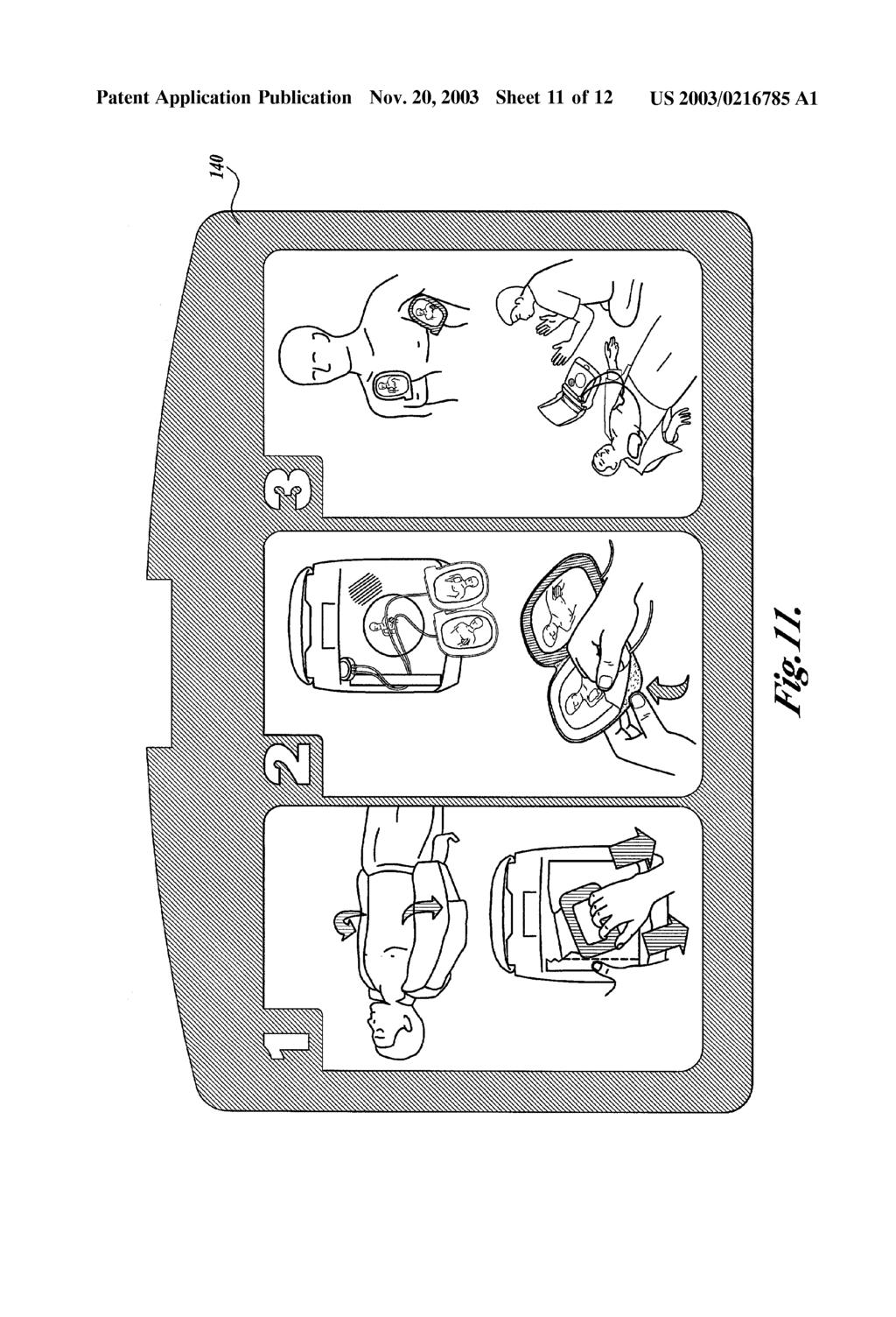
18 US 2003/ A1 Nov. 20, Returning to FIG. 3, given the difficulty a lay person may have opening the electrode package 120, apply ing the defibrillation electrodes to the patient and operating the AED, the AED 100 may also include another layer of user interface component that is made available to the operator Simultaneously with the electrode package 120 when the lid 104 is opened. More specifically, a reference card 140 may be mounted to a bottom surface 138 of the lid 104 that graphically depicts a Sequence of the basic instruc tions to be followed by the operator during use of the AED. FIG. 11 shows a close-up view of the reference card 140. The illustrated embodiment of the reference card 140 depicts the following basic instructions: (1) remove the patients clothing and pull the handle on the electrode package; (2) remove the electrodes from the package and peel them off the liner; and (3) apply the electrodes to the patient's chest, Stand clear and follow the prompts (visual and/or aural) issued by the AED. Accordingly, the operator is given an immediate and always Visible idea of what Steps must be taken to operate the device and treat the patient. Those skilled in the art will appreciate, however, that the reference card 140 may include any instructions, diagrams, text, etc. deemed desirable by the manufacturer In one embodiment of the present invention, the operator is further guided through the layered user interface in the operation of the device and treatment of the patient by a Series of audible instructions or voice prompts provided by the AED 100 to the operator via an audio speaker 152 (see FIG. 6), along with electrically driven visual signals, such as the electrode indicators 162, 164 and flashing shock key 170. One skilled in the art will understand that any of a wide variety of combinations of hardware circuitry and Software programming can be used to detect or otherwise time the Sequence of operator actions and then provide the corre sponding Signals to the audio Speaker 152 and driven visual elements. Particular details of Such circuitry and Software need not be disclosed for one skilled in the art to understand the teachings of the present invention. However, one example of Such circuitry and Software as implemented in an AED is described in commonly assigned U.S. Pat. No. 6,334,070, entitled Visual and Aural User Interface for an Automated External Defibrillator, issued Dec. 25, 2001, and Specifically incorporated herein by reference Referring to FIG. 12, a flow diagram is presented to depict the Sequence of audible and electrically driven visual instructions issued by the AED 100 for the scenario in which a defibrillation shock is actually delivered. A prompt ing routine 200 is executed by the AED 100, and includes issuing audible instructions via the audio Speaker 152 and electrically driven visual instructions via the electrode indi cators 162, 164 and flashing shock key ) The routine 200 begins in a decision block 210 testing whether the AED 100 has been activated. Once the condition of block 210 is met, the routine 200 continues to block 220, in which the AED 100 issues audible instructions to the operator concerning calling for help, removing cloth ing to expose the patient's chest, and opening the electrode package 120. The routine 200 continues with a decision block 230 testing whether the electrode package 120 has been opened. If not, the routine 200 returns to block Once the condition of decision block 230 is met, the routine 200 then continues to block 240, in which the AED 100 issues audible instructions concerning removal of the defibrillation electrodes 142, 144 from the electrode package 120 and removal of the electrodes from the liner 146. The routine 200 then continues to a decision block 250 testing whether the defibrillation electrodes 142, 144 have been removed from the liner 146. If not, the routine 200 returns to block 240 and the appropriate audible instructions are repeated. 0046) Once the condition of decision block 250 is met, the routine 200 then continues with a third instructional step 260, in which the AED 100 issues audible instructions concerning placement of the defibrillation electrodes 142, 144 on the patient s chest and lights up the LEDs 162, 164 of the electrode status display 160 accordingly. The routine 200 continues to a decision block 270 and tests whether the defibrillation electrodes 142,144 have been properly placed on the patient. If not, the routine 200 returns to block 260 to repeat the appropriate Visual and aural instructions to the operator Once the condition of decision block 270 is met, the routine 200 continues to block 280, in which the AED 100 issues visual information confirming the proper place ment of the defibrillation electrodes 142,144 (i.e., lights the LEDs of the electrode status display 160 green) and audible information concerning evaluation of the patient's heart rhythm and preparations for delivering a defibrillation pulse. The AED 100 then issues visual instructions (e.g., flashing shock key 170) and audible instructions to the operator to press the shock key 170 and initiate delivery of the defibril lation pulse to the patient Those skilled in the art will appreciate that a number of well-known operations are not presented in the flow diagram of FIG. 12, such as instructions relating to patient movement (if detected), decisions by the AED diag nostic circuitry not to shock, instructions relating to CPR, and the like. Such AED operations are described in U.S. Pat. No. 6,334,070, already incorporated herein by reference. Those skilled in the art will further appreciate that various operations can be omitted from the flow diagram of FIG. 12 and performed and/or input by an operator or other device, or Substituted with a time-out function without departing from the Spirit and Scope of the present invention While certain embodiments of the invention have been illustrated and described, those skilled in the art will appreciate that various changes can be made without depart ing from the Spirit and Scope of the invention. Additional layers of user interface components may be added as appro priate to assist in the operation of the device, treatment of the patient or perhaps the maintenance of the device. For example, as illustrated in FIGS. 1 and 3, the AED 100 may include a readiness display 110 that includes various Sym bols indicating the Status of the AED, Such as indicating its readiness for use, the need to replace a battery unit, the need for inspection or repair, or other indication as would be understood by those skilled in the art. The AED 100 may also include a window 112 in the lid 104 through which an electrode expiration date 114 Stamped on the upper Surface of the electrode package 120 (see FIG. 3) can be seen by the operator when the lid is closed. Together these components may be referred to in the context of the present invention as a status layer of the user interface.

19 US 2003/ A1 Nov. 20, 2003 We claim: 1. A medical device for patient treatment comprising a plurality of layered user interface components, each Succes Sive layer of user interface component becoming available to an operator of the medical device as the user interface component becomes appropriate during the operation of the medical device and patient treatment. 2. The medical device of claim 1, wherein the plurality of layered user interface components includes: an activator used by the operator to activate the medical device; a connector used by the operator to connect the medical device to the patient; and an initiator used by the operator to initiate treatment of the patient by the medical device. 3. The medical device of claim 2, wherein the plurality of layered user interface components further includes: activation instructions concerning operator use of the activator; connection instructions concerning operator use of the connector; and treatment instructions concerning operator use of the initiator. 4. The medical device of claim 3, wherein each of the activation instructions, connection instructions, and treat ment instructions includes visual, audible, written, or dia grammatic instructions. 5. The medical device of claim 2, wherein the connector becomes available to the operator only after the operator has used the activator. 6. The medical device of claim 2, wherein the initiator becomes available to the operator only after the operator has used the connector. 7. The medical device of claim 2, wherein the activator includes an on/off actuator. 8. The medical device of claim 7, wherein the on/off actuator is a button depressable by the operator. 9. The medical device of claim 2, wherein the activator includes a lid movable between closed and open positions. 10. The medical device of claim 9, wherein movement of the lid to the open position activates the medical device. 11. The medical device of claim 9, wherein the activator further includes a lid-release member actuatable by the operator to release the lid for movement to the open position. 12. The medical device of claim 11, wherein actuation of the lid-release member activates the medical device. 13. A layered user interface for an external defibrillator comprising: an activation layer that guides an operator to activate the defibrillator; an electrode application layer made available to the operator Subsequent to the activation layer that guides the operator to apply electrodes to a patient; and a defibrillation pulse delivery layer made available to the operator Subsequent to the electrode application layer that guides the operator through delivery of a defibril lation pulse to the patient. 14. The layered user interface of claim 13, wherein the activation layer comprises an on/off actuator used by the operator to activate the defibrillator. 15. The layered user interface of claim 14, wherein the on/off actuator is a button contrastingly configured and colored to draw the attention of the operator. 16. The layered user interface of claim 13, wherein the electrode application layer comprises an electrode package containing the electrodes, and instructions for opening the package and for applying the electrodes to the patient. 17. The layered user interface of claim 16, wherein the instructions include audible instructions. 18. The layered user interface of claim 16, wherein the instructions include Visual instructions. 19. The layered user interface of claim 16, wherein the instructions include written instructions. 20. The layered user interface of claim 16, wherein the instructions include diagrammatic instructions. 21. The layered user interface of claim 13, wherein the defibrillation pulse delivery layer comprises a shock key actuatable by the operator to initiate delivery of the defibril lation pulse, and instructions for actuating the shock key. 22. The layered user interface of claim 21, wherein the instructions include Visual instructions. 23. The layered user interface of claim 21, wherein the instructions include audible instructions. 24. The layered user interface of claim 13 further com prising a Status layer that indicates to the operator the Status of the defibrillator. 25. The layered user interface of claim 24, wherein the Status layer comprises a readiness display which indicates the status of components of the defibrillator. 26. The layered user interface of claim 24, wherein the Status layer comprises an electrode expiration date display that indicates the status of the defibrillator's electrodes. 27. The layered user interface of claim 13, wherein the defibrillation pulse delivery layer comprises instructions for guiding the operator through delivery of the defibrillation pulse, wherein the defibrillator automatically initiates deliv ery of the defibrillation pulse. 28. An external defibrillator adapted to lead an operator through a Sequence of operations to deliver a defibrillation Shock to a patient, comprising: a case having a first indicator presented to the operator and directing the operator to perform a first of the Sequence of operations, an electrode package disposed within the case and made accessible to the operator only upon performance of the first of the Sequence of operations, the electrode pack age having a Second indicator presented to the operator and directing the operator to perform a Second of the Sequence of operations, and defibrillation electrodes disposed within the electrode package and made accessible to the operator only upon performance of the Second of the Sequence of opera tions, the defibrillation electrodes having a third indi cator presented to the operator and directing the opera tor to perform a third of the Sequence of operations. 29. The external defibrillator of claim 28, wherein the first indicator includes an on/off button configured and colored to contrast with the case, and wherein the first of the Sequence of operations includes activating the defibrillator. 30. The external defibrillator of claim 28, wherein the electrode package includes a handle actuatable by the opera tor to open the electrode package, and wherein the Second indicator includes a diagram depicting pulling the handle to

20 US 2003/ A1 Nov. 20, 2003 open the electrode package, and wherein the Second of the Sequence of operations includes opening the electrode pack age. 31. The external defibrillator of claim 28, wherein the third indicator includes a diagram depicting placement of the defibrillation electrodes on the patient, and wherein the third of the Sequence of operations includes placing the defibril lation electrodes on the patient. 32. The external defibrillator of claim 28 further compris ing an audio Speaker operable to issue a Sequence of audible instructions corresponding with the Sequence of operations. 33. The external defibrillator of claim 32, wherein each of audible instructions is issued following completion of a prior one of the corresponding operations. 34. The external defibrillator of claim 28, wherein the defibrillation electrodes have a fourth indicator presented to the operator and directing the operator to perform a fourth of the Sequence of operations. 35. The external defibrillator of claim 34, wherein the third indicator directs the operator to remove the defibrilla tion electrodes from a liner, and wherein the fourth indicator includes a diagram depicting placement of the defibrillation electrodes on the patient. 36. The external defibrillator of claim 28 further compris ing a shock control button disposed within the case and made accessible to the operator only upon performance of the Second of the Sequence of operations, the shock control button being actuatable by the operator to initiate the deliv ery of the defibrillation shock to the patient, and the shock control button having a fourth indicator presented to the operator and directing the operator to perform a fourth of the Sequence of operations. 37. The external defibrillator of claim 36, wherein the fourth indicator includes a visual signal attracting the opera tor's attention, and wherein the fourth of the Sequence of operations includes actuating the shock control button. 38. A layered user interface for an external defibrillator comprising: an activation device used by an operator of the defibril lator to activate the defibrillator; an electrode package containing defibrillation electrodes, wherein the electrode package is made available to the operator after activation of the defibrillator; and a shock key used by the operator to initiate a defibrillation pulse, wherein the Shock key is made available to the operator after the electrode package has been deployed. 39. The layered user interface of claim 38 further com prising a prompting System for prompting the operator with instructions for deploying the electrode package. 40. The layered user interface of claim 39, wherein the prompting System includes written instructions for deploy ing the electrode package. 41. The layered user interface of claim 39, wherein the prompting System includes audible instructions for deploy ing the electrode package. 42. The layered user interface of claim 39, wherein the prompting System includes diagrammatic instructions for deploying the electrode package. 43. The layered user interface of claim 39, wherein the prompting System includes visual cues for deploying the electrode package. 44. The layered user interface of claim 39, wherein the prompting System further prompts the operator to activate the shock key if a shockable heart rhythm has been detected. 45. The layered user interface of claim 44, wherein the prompting System includes audible instructions to activate the Shock key. 46. The layered user interface of claim 44, wherein the prompting System includes visual cues to activate the shock key. 47. A method for providing a user interface to an operator of an external defibrillator, the method comprising: drawing the attention of the operator to an actuator for activating the defibrillator; upon activating the defibrillator, revealing to the operator an electrode package containing defibrillation elec trodes; providing instructions to the operator for deploying the electrode package; and upon deploying the electrode package, revealing a shock key to the operator for initiating delivery of a defibril lation pulse. 48. The method of claim 47, wherein providing instruc tions to the operator includes providing visual, audible, written, or diagrammatic instructions. 49. The method of claim 47 further comprising providing instructions to the operator for actuating the shock key. 50. The method of claim 47, wherein providing the instructions for actuating the shock key includes providing Visual or audible instructions. 51. The method of claim 47, wherein providing instruc tions for deploying the electrode package includes providing instructions for opening the electrode package and providing instructions for deploying the defibrillation electrodes. 52. A method of providing a user interface to an operator of an external defibrillator, the method comprising: instructing the operator concerning activating the defibril lator; upon the operator activating the defibrillator, providing the operator with an electrode package having an opener that is actuatable by the operator; instructing the operator concerning opening the electrode package; instructing the operator concerning removing electrodes from the electrode package; instructing the operator concerning placement of the electrodes on the patient; and upon the operator placing the electrodes on the patient, instructing the operator concerning care giving opera tions. 53. The method of claim 52, wherein instructing the operator concerning activating the defibrillator includes pro Viding the operator with a button actuatable by the operator to activate the defibrillator. 54. The method of claim 52, wherein instructing the operator concerning activating the defibrillator includes pro Viding the operator with a lid-release button actuatable by the operator to release a lid of the defibrillator.

21 US 2003/ A1 Nov. 20, The method of claim 54, wherein the actuation of the lid-release button initiates activation of the defibrillator. 56. The method of claim 54, wherein opening the lid initiates activation of the defibrillator. 57. The method of claim 52, wherein instructing the operator concerning opening the electrode package includes providing written information concerning opening the elec trode package. 58. The method of claim 52, wherein instructing the operator concerning opening the electrode package includes producing audible information concerning opening the elec trode package. 59. The method of claim 52, wherein instructing the operator concerning opening the electrode package includes providing a diagram depicting opening the electrode pack age. 60. The method of claim 52, wherein instructing the operator concerning removing the electrodes includes pro Viding written information concerning removing the elec trodes from the electrode package. 61. The method of claim 52, wherein instructing the operator concerning removing the electrodes includes pro ducing audible information concerning removing the elec trodes from the electrode package. 62. The method of claim 52, wherein instructing the operator concerning removing the electrodes includes pro Viding a diagram depicting removing the electrodes from the electrode package. 63. The method of claim 52, wherein instructing the operator concerning positioning the electrodes includes pro Viding written information concerning positioning the elec trodes on the patient. 64. The method of claim 52, wherein instructing the operator concerning positioning the electrodes includes pro ducing audible information concerning positioning the elec trodes on the patient. 65. The method of claim 52, wherein instructing the operator concerning positioning the electrodes includes pro Viding a diagram depicting positioning the electrodes on the patient. 66. The method of claim 52, wherein instructing the operator concerning positioning the electrodes includes pro Viding to the operator Status information concerning the application of the electrodes to the patient. 67. The method of claim 66, wherein providing to the operator Status information includes producing a visual Status Signal having first and Second States respectively corresponding to the application of the electrodes to the patient and the nonapplication of the electrodes to the patient. 68. The method of claim 66, wherein providing to the operator Status information includes producing an audible instruction prompting the operator to check the application of the electrodes to the patient. 69. The method of claim 52, wherein instructing the operator concerning care giving operations includes provid ing written information concerning care giving operations. 70. The method of claim 52, wherein instructing the operator concerning care giving operations includes produc ing audible information concerning care giving operations. 71. The method of claim 52, wherein instructing the operator concerning care giving operations includes provid ing a diagram depicting care giving operations. 72. The method of claim 52 further comprising: Subsequent to the operator opening the electrode package, providing the operator with a shock control button actuatable by the operator to initiate delivery of the defibrillation shock to the patient; and wherein instructing the operator concerning care giving operations includes instructing the operator concerning actuation of the Shock control button. 73. The method of claim 72, wherein instructing the operator concerning actuation of the Shock control button includes producing audible information concerning actua tion of the shock control button. 74. The method of claim 72, wherein instructing the operator concerning actuation of the Shock control button includes producing visual information concerning actuation of the shock control button. 75. The method of claim 52, wherein after the operator is instructed concerning care giving operations, the defibrilla tor automatically delivers a defibrillation pulse if a shock able heart rhythm is detected. 76. A method of leading an operator through a Sequence of operations using an external defibrillator to deliver a defibrillation shock to a patient, the method comprising: presenting a first indicator to the operator to direct the operator to activate the defibrillator; upon the operator activating the defibrillator, providing the operator with an electrode package and presenting a Second indicator to the operator to direct the operator to open the electrode package; upon the operator opening the electrode package, provid ing the operator with first and second defibrillation electrodes and presenting a third indicator to the opera tor concerning application of the electrodes to the patient; and upon the operator placing the electrodes on the patient, instructing the operator concerning care giving opera tions. 77. The method of claim 76, wherein presenting the first indicator includes presenting an on/off actuator. 78. The method of claim 76, wherein presenting the first indicator includes presenting visual instructions concerning activating the defibrillator. 79. The method of claim 76, wherein presenting the Second indicator includes presenting a diagram depicting opening the electrode package 80. The method of claim 76, wherein presenting the Second indicator includes presenting an opener configured and colored to contrast with the electrode package. 81. The method of claim 80, wherein the opener is a handle. 82. The method of claim 80, wherein presenting the Second indicator further includes presenting a diagram depicting pulling the handle. 83. The method of claim 76, wherein presenting the Second indicator includes presenting audible instructions concerning opening the electrode package. 84. The method of claim 76, wherein presenting the third indicator includes presenting a diagram depicting placement of the electrodes on the patient.

22 US 2003/ A1 Nov. 20, The method of claim 76, wherein presenting the third indicator includes presenting audible instructions concern ing application of the electrodes to the patient. 86. The method of claim 76, wherein presenting the third indicator includes presenting instructions to remove the defibrillation electrodes from a liner. 87. The method of claim 86, wherein the instructions include Visual cues. 88. The method of claim 86, wherein the instructions include audible instructions. 89. The method of claim 76, wherein instructing the operator concerning care giving operations includes present ing a diagram depicting care giving operations. 90. The method of claim 76, wherein instructing the operator concerning care giving operations includes present ing audible instructions concerning care giving operations. 91. The method of claim 76 further comprising: upon the operator opening the electrode package, provid ing the operator with a shock control button; and wherein instructing the operator concerning care giving operations includes presenting a fourth indicator to the operator concerning actuation of the Shock control button. 92. The method of claim 91, wherein presenting the fourth indicator includes issuing a visible signal. 93. The method of claim 91, wherein presenting the fourth indicator includes presenting audible instructions concern ing actuation of the shock control button. 94. The method of claim 76, wherein after the operator is instructed concerning care giving operations, the defibrilla tor automatically delivers a defibrillation pulse if a shock able rhythm is detected. k k k k k
USOO A United States Patent (19) 11 Patent Number: 5,850,807 Keeler (45) Date of Patent: Dec. 22, 1998
 11 Patent Number: 5,850,807 Keeler (45) Date of Patent: Dec. 22, 1998") USOO.5850807A United States Patent (19) 11 Patent Number: 5,850,807 Keeler (45) Date of Patent: Dec. 22, 1998 54). ILLUMINATED PET LEASH Primary Examiner Robert P. Swiatek Assistant Examiner James S. Bergin
USOO.5850807A United States Patent (19) 11 Patent Number: 5,850,807 Keeler (45) Date of Patent: Dec. 22, 1998 54). ILLUMINATED PET LEASH Primary Examiner Robert P. Swiatek Assistant Examiner James S. Bergin
(12) Patent Application Publication (10) Pub. No.: US 2013/ A1
 Patent Application Publication (10) Pub. No.: US 2013/ A1") (19) United States US 2013 0100156A1 (12) Patent Application Publication (10) Pub. No.: US 2013/0100156A1 JANG et al. (43) Pub. Date: Apr. 25, 2013 (54) PORTABLE TERMINAL CAPABLE OF (30) Foreign Application
(19) United States US 2013 0100156A1 (12) Patent Application Publication (10) Pub. No.: US 2013/0100156A1 JANG et al. (43) Pub. Date: Apr. 25, 2013 (54) PORTABLE TERMINAL CAPABLE OF (30) Foreign Application
III... III: III. III.
 (19) United States US 2015 0084.912A1 (12) Patent Application Publication (10) Pub. No.: US 2015/0084912 A1 SEO et al. (43) Pub. Date: Mar. 26, 2015 9 (54) DISPLAY DEVICE WITH INTEGRATED (52) U.S. Cl.
(12) Patent Application Publication (10) Pub. No.: US 2005/ A1
 Patent Application Publication (10) Pub. No.: US 2005/ A1") (19) United States US 20050008347A1 (12) Patent Application Publication (10) Pub. No.: US 2005/0008347 A1 Jung et al. (43) Pub. Date: Jan. 13, 2005 (54) METHOD OF PROCESSING SUBTITLE STREAM, REPRODUCING
(19) United States US 20050008347A1 (12) Patent Application Publication (10) Pub. No.: US 2005/0008347 A1 Jung et al. (43) Pub. Date: Jan. 13, 2005 (54) METHOD OF PROCESSING SUBTITLE STREAM, REPRODUCING
1 s ); PASS. (10) Patent No.: US 6,823,209 B2. (45) Date of Patent: Nov. 23, : 461Nu. (12) United States Patent Olson et al.
; PASS. (10) Patent No.: US 6,823,209 B2. (45) Date of Patent: Nov. 23, : 461Nu. (12) United States Patent Olson et al.") (12) United States Patent Olson et al. USOO6823209B2 (10) Patent No.: (45) Date of Patent: Nov. 23, 2004 (54) (75) (73) (21) (22) (65) (51) (52) (58) (56) ELECTROCARDIOGRAM FILTER Inventors: Dana J. Olson,
(12) United States Patent Olson et al. USOO6823209B2 (10) Patent No.: (45) Date of Patent: Nov. 23, 2004 (54) (75) (73) (21) (22) (65) (51) (52) (58) (56) ELECTROCARDIOGRAM FILTER Inventors: Dana J. Olson,
(12) United States Patent (10) Patent No.: US 6,885,157 B1
 United States Patent (10) Patent No.: US 6,885,157 B1") USOO688.5157B1 (12) United States Patent (10) Patent No.: Cok et al. (45) Date of Patent: Apr. 26, 2005 (54) INTEGRATED TOUCH SCREEN AND OLED 6,504,530 B1 1/2003 Wilson et al.... 345/173 FLAT-PANEL DISPLAY
USOO688.5157B1 (12) United States Patent (10) Patent No.: Cok et al. (45) Date of Patent: Apr. 26, 2005 (54) INTEGRATED TOUCH SCREEN AND OLED 6,504,530 B1 1/2003 Wilson et al.... 345/173 FLAT-PANEL DISPLAY
III. (12) United States Patent US 6,995,345 B2. Feb. 7, (45) Date of Patent: (10) Patent No.: (75) Inventor: Timothy D. Gorbold, Scottsville, NY
 United States Patent US 6,995,345 B2. Feb. 7, (45) Date of Patent: (10) Patent No.: (75) Inventor: Timothy D. Gorbold, Scottsville, NY") USOO6995.345B2 (12) United States Patent Gorbold (10) Patent No.: (45) Date of Patent: US 6,995,345 B2 Feb. 7, 2006 (54) ELECTRODE APPARATUS FOR STRAY FIELD RADIO FREQUENCY HEATING (75) Inventor: Timothy
USOO6995.345B2 (12) United States Patent Gorbold (10) Patent No.: (45) Date of Patent: US 6,995,345 B2 Feb. 7, 2006 (54) ELECTRODE APPARATUS FOR STRAY FIELD RADIO FREQUENCY HEATING (75) Inventor: Timothy
(12) United States Patent
 United States Patent") (12) United States Patent Ali USOO65O1400B2 (10) Patent No.: (45) Date of Patent: Dec. 31, 2002 (54) CORRECTION OF OPERATIONAL AMPLIFIER GAIN ERROR IN PIPELINED ANALOG TO DIGITAL CONVERTERS (75) Inventor:
(12) United States Patent Ali USOO65O1400B2 (10) Patent No.: (45) Date of Patent: Dec. 31, 2002 (54) CORRECTION OF OPERATIONAL AMPLIFIER GAIN ERROR IN PIPELINED ANALOG TO DIGITAL CONVERTERS (75) Inventor:
(12) United States Patent (10) Patent No.: US 7.043,750 B2. na (45) Date of Patent: May 9, 2006
 United States Patent (10) Patent No.: US 7.043,750 B2. na (45) Date of Patent: May 9, 2006") US00704375OB2 (12) United States Patent (10) Patent No.: US 7.043,750 B2 na (45) Date of Patent: May 9, 2006 (54) SET TOP BOX WITH OUT OF BAND (58) Field of Classification Search... 725/111, MODEMAND CABLE
US00704375OB2 (12) United States Patent (10) Patent No.: US 7.043,750 B2 na (45) Date of Patent: May 9, 2006 (54) SET TOP BOX WITH OUT OF BAND (58) Field of Classification Search... 725/111, MODEMAND CABLE
(12) United States Patent (10) Patent No.: US 6,275,266 B1
 United States Patent (10) Patent No.: US 6,275,266 B1") USOO6275266B1 (12) United States Patent (10) Patent No.: Morris et al. (45) Date of Patent: *Aug. 14, 2001 (54) APPARATUS AND METHOD FOR 5,8,208 9/1998 Samela... 348/446 AUTOMATICALLY DETECTING AND 5,841,418
USOO6275266B1 (12) United States Patent (10) Patent No.: Morris et al. (45) Date of Patent: *Aug. 14, 2001 (54) APPARATUS AND METHOD FOR 5,8,208 9/1998 Samela... 348/446 AUTOMATICALLY DETECTING AND 5,841,418
(12) Patent Application Publication (10) Pub. No.: US 2008/ A1
 Patent Application Publication (10) Pub. No.: US 2008/ A1") US 2008O1891. 14A1 (19) United States (12) Patent Application Publication (10) Pub. No.: US 2008/0189114A1 FAIL et al. (43) Pub. Date: Aug. 7, 2008 (54) METHOD AND APPARATUS FOR ASSISTING (22) Filed: Mar.
US 2008O1891. 14A1 (19) United States (12) Patent Application Publication (10) Pub. No.: US 2008/0189114A1 FAIL et al. (43) Pub. Date: Aug. 7, 2008 (54) METHOD AND APPARATUS FOR ASSISTING (22) Filed: Mar.
(12) United States Patent (10) Patent No.: US 7,605,794 B2
 United States Patent (10) Patent No.: US 7,605,794 B2") USOO7605794B2 (12) United States Patent (10) Patent No.: Nurmi et al. (45) Date of Patent: Oct. 20, 2009 (54) ADJUSTING THE REFRESH RATE OFA GB 2345410 T 2000 DISPLAY GB 2378343 2, 2003 (75) JP O309.2820
USOO7605794B2 (12) United States Patent (10) Patent No.: Nurmi et al. (45) Date of Patent: Oct. 20, 2009 (54) ADJUSTING THE REFRESH RATE OFA GB 2345410 T 2000 DISPLAY GB 2378343 2, 2003 (75) JP O309.2820
(12) Patent Application Publication (10) Pub. No.: US 2004/ A1
 Patent Application Publication (10) Pub. No.: US 2004/ A1") (19) United States US 004063758A1 (1) Patent Application Publication (10) Pub. No.: US 004/063758A1 Lee et al. (43) Pub. Date: Dec. 30, 004 (54) LINE ON GLASS TYPE LIQUID CRYSTAL (30) Foreign Application
(19) United States US 004063758A1 (1) Patent Application Publication (10) Pub. No.: US 004/063758A1 Lee et al. (43) Pub. Date: Dec. 30, 004 (54) LINE ON GLASS TYPE LIQUID CRYSTAL (30) Foreign Application
(12) Patent Application Publication (10) Pub. No.: US 2009/ A1
 Patent Application Publication (10) Pub. No.: US 2009/ A1") US 2009017.4444A1 (19) United States (12) Patent Application Publication (10) Pub. No.: US 2009/0174444 A1 Dribinsky et al. (43) Pub. Date: Jul. 9, 2009 (54) POWER-ON-RESET CIRCUIT HAVING ZERO (52) U.S.
US 2009017.4444A1 (19) United States (12) Patent Application Publication (10) Pub. No.: US 2009/0174444 A1 Dribinsky et al. (43) Pub. Date: Jul. 9, 2009 (54) POWER-ON-RESET CIRCUIT HAVING ZERO (52) U.S.
USOO A United States Patent (19) 11 Patent Number: 5,822,052 Tsai (45) Date of Patent: Oct. 13, 1998
 11 Patent Number: 5,822,052 Tsai (45) Date of Patent: Oct. 13, 1998") USOO5822052A United States Patent (19) 11 Patent Number: Tsai (45) Date of Patent: Oct. 13, 1998 54 METHOD AND APPARATUS FOR 5,212,376 5/1993 Liang... 250/208.1 COMPENSATING ILLUMINANCE ERROR 5,278,674
USOO5822052A United States Patent (19) 11 Patent Number: Tsai (45) Date of Patent: Oct. 13, 1998 54 METHOD AND APPARATUS FOR 5,212,376 5/1993 Liang... 250/208.1 COMPENSATING ILLUMINANCE ERROR 5,278,674
(12) Patent Application Publication (10) Pub. No.: US 2003/ A1
 Patent Application Publication (10) Pub. No.: US 2003/ A1") US 2003O22O142A1 (19) United States (12) Patent Application Publication (10) Pub. No.: US 2003/0220142 A1 Siegel (43) Pub. Date: Nov. 27, 2003 (54) VIDEO GAME CONTROLLER WITH Related U.S. Application Data
US 2003O22O142A1 (19) United States (12) Patent Application Publication (10) Pub. No.: US 2003/0220142 A1 Siegel (43) Pub. Date: Nov. 27, 2003 (54) VIDEO GAME CONTROLLER WITH Related U.S. Application Data
(12) Patent Application Publication (10) Pub. No.: US 2008/ A1
 Patent Application Publication (10) Pub. No.: US 2008/ A1") (19) United States US 2008O144051A1 (12) Patent Application Publication (10) Pub. No.: US 2008/0144051A1 Voltz et al. (43) Pub. Date: (54) DISPLAY DEVICE OUTPUT ADJUSTMENT SYSTEMAND METHOD (76) Inventors:
(19) United States US 2008O144051A1 (12) Patent Application Publication (10) Pub. No.: US 2008/0144051A1 Voltz et al. (43) Pub. Date: (54) DISPLAY DEVICE OUTPUT ADJUSTMENT SYSTEMAND METHOD (76) Inventors:
United States Patent 19 11) 4,450,560 Conner
 4,450,560 Conner") United States Patent 19 11) 4,4,560 Conner 54 TESTER FOR LSI DEVICES AND DEVICES (75) Inventor: George W. Conner, Newbury Park, Calif. 73 Assignee: Teradyne, Inc., Boston, Mass. 21 Appl. No.: 9,981 (22
United States Patent 19 11) 4,4,560 Conner 54 TESTER FOR LSI DEVICES AND DEVICES (75) Inventor: George W. Conner, Newbury Park, Calif. 73 Assignee: Teradyne, Inc., Boston, Mass. 21 Appl. No.: 9,981 (22
o VIDEO A United States Patent (19) Garfinkle u PROCESSOR AD OR NM STORE 11 Patent Number: 5,530,754 45) Date of Patent: Jun.
 Garfinkle u PROCESSOR AD OR NM STORE 11 Patent Number: 5,530,754 45) Date of Patent: Jun.") United States Patent (19) Garfinkle 54) VIDEO ON DEMAND 76 Inventor: Norton Garfinkle, 2800 S. Ocean Blvd., Boca Raton, Fla. 33432 21 Appl. No.: 285,033 22 Filed: Aug. 2, 1994 (51) Int. Cl.... HO4N 7/167
United States Patent (19) Garfinkle 54) VIDEO ON DEMAND 76 Inventor: Norton Garfinkle, 2800 S. Ocean Blvd., Boca Raton, Fla. 33432 21 Appl. No.: 285,033 22 Filed: Aug. 2, 1994 (51) Int. Cl.... HO4N 7/167
(12) Patent Application Publication (10) Pub. No.: US 2010/ A1
 Patent Application Publication (10) Pub. No.: US 2010/ A1") (19) United States (12) Patent Application Publication (10) Pub. No.: US 2010/001381.6 A1 KWak US 20100013816A1 (43) Pub. Date: (54) PIXEL AND ORGANIC LIGHT EMITTING DISPLAY DEVICE USING THE SAME (76)
(19) United States (12) Patent Application Publication (10) Pub. No.: US 2010/001381.6 A1 KWak US 20100013816A1 (43) Pub. Date: (54) PIXEL AND ORGANIC LIGHT EMITTING DISPLAY DEVICE USING THE SAME (76)
(12) United States Patent (10) Patent No.: US 6,462,508 B1. Wang et al. (45) Date of Patent: Oct. 8, 2002
 United States Patent (10) Patent No.: US 6,462,508 B1. Wang et al. (45) Date of Patent: Oct. 8, 2002") USOO6462508B1 (12) United States Patent (10) Patent No.: US 6,462,508 B1 Wang et al. (45) Date of Patent: Oct. 8, 2002 (54) CHARGER OF A DIGITAL CAMERA WITH OTHER PUBLICATIONS DATA TRANSMISSION FUNCTION
USOO6462508B1 (12) United States Patent (10) Patent No.: US 6,462,508 B1 Wang et al. (45) Date of Patent: Oct. 8, 2002 (54) CHARGER OF A DIGITAL CAMERA WITH OTHER PUBLICATIONS DATA TRANSMISSION FUNCTION
(12) Patent Application Publication (10) Pub. No.: US 2015/ A1
 Patent Application Publication (10) Pub. No.: US 2015/ A1") US 20150358554A1 (19) United States (12) Patent Application Publication (10) Pub. No.: US 2015/0358554 A1 Cheong et al. (43) Pub. Date: Dec. 10, 2015 (54) PROACTIVELY SELECTINGA Publication Classification
US 20150358554A1 (19) United States (12) Patent Application Publication (10) Pub. No.: US 2015/0358554 A1 Cheong et al. (43) Pub. Date: Dec. 10, 2015 (54) PROACTIVELY SELECTINGA Publication Classification
(12) Patent Application Publication (10) Pub. No.: US 2005/ A1
 Patent Application Publication (10) Pub. No.: US 2005/ A1") (19) United States US 2005.0089284A1 (12) Patent Application Publication (10) Pub. No.: US 2005/0089284A1 Ma (43) Pub. Date: Apr. 28, 2005 (54) LIGHT EMITTING CABLE WIRE (76) Inventor: Ming-Chuan Ma, Taipei
(19) United States US 2005.0089284A1 (12) Patent Application Publication (10) Pub. No.: US 2005/0089284A1 Ma (43) Pub. Date: Apr. 28, 2005 (54) LIGHT EMITTING CABLE WIRE (76) Inventor: Ming-Chuan Ma, Taipei
(12) Patent Application Publication (10) Pub. No.: US 2010/ A1
 Patent Application Publication (10) Pub. No.: US 2010/ A1") US 2010.0097.523A1. (19) United States (12) Patent Application Publication (10) Pub. No.: US 2010/0097523 A1 SHIN (43) Pub. Date: Apr. 22, 2010 (54) DISPLAY APPARATUS AND CONTROL (30) Foreign Application
US 2010.0097.523A1. (19) United States (12) Patent Application Publication (10) Pub. No.: US 2010/0097523 A1 SHIN (43) Pub. Date: Apr. 22, 2010 (54) DISPLAY APPARATUS AND CONTROL (30) Foreign Application
(12) Patent Application Publication (10) Pub. No.: US 2007/ A1
 Patent Application Publication (10) Pub. No.: US 2007/ A1") (19) United States (12) Patent Application Publication (10) Pub. No.: US 2007/0230902 A1 Shen et al. US 20070230902A1 (43) Pub. Date: Oct. 4, 2007 (54) (75) (73) (21) (22) (60) DYNAMIC DISASTER RECOVERY
(19) United States (12) Patent Application Publication (10) Pub. No.: US 2007/0230902 A1 Shen et al. US 20070230902A1 (43) Pub. Date: Oct. 4, 2007 (54) (75) (73) (21) (22) (60) DYNAMIC DISASTER RECOVERY
(12) Patent Application Publication (10) Pub. No.: US 2005/ A1
 Patent Application Publication (10) Pub. No.: US 2005/ A1") (19) United States US 2005O285825A1 (12) Patent Application Publication (10) Pub. No.: US 2005/0285825A1 E0m et al. (43) Pub. Date: Dec. 29, 2005 (54) LIGHT EMITTING DISPLAY AND DRIVING (52) U.S. Cl....
(19) United States US 2005O285825A1 (12) Patent Application Publication (10) Pub. No.: US 2005/0285825A1 E0m et al. (43) Pub. Date: Dec. 29, 2005 (54) LIGHT EMITTING DISPLAY AND DRIVING (52) U.S. Cl....
(12) Patent Application Publication (10) Pub. No.: US 2011/ A1
 Patent Application Publication (10) Pub. No.: US 2011/ A1") (19) United States US 2011 0320948A1 (12) Patent Application Publication (10) Pub. No.: US 2011/0320948 A1 CHO (43) Pub. Date: Dec. 29, 2011 (54) DISPLAY APPARATUS AND USER Publication Classification INTERFACE
(19) United States US 2011 0320948A1 (12) Patent Application Publication (10) Pub. No.: US 2011/0320948 A1 CHO (43) Pub. Date: Dec. 29, 2011 (54) DISPLAY APPARATUS AND USER Publication Classification INTERFACE
(12) Patent Application Publication (10) Pub. No.: US 2003/ A1
 Patent Application Publication (10) Pub. No.: US 2003/ A1") US 2003OO3O269A1 (19) United States (12) Patent Application Publication (10) Pub. No.: US 2003/0030269 A1 Hernandez (43) Pub. Date: (54) EXPENSE RECEIPT DIARY WITH (52) U.S. Cl.... 283/63.1 ADHESIVE STRIP
US 2003OO3O269A1 (19) United States (12) Patent Application Publication (10) Pub. No.: US 2003/0030269 A1 Hernandez (43) Pub. Date: (54) EXPENSE RECEIPT DIARY WITH (52) U.S. Cl.... 283/63.1 ADHESIVE STRIP
(12) Patent Application Publication (10) Pub. No.: US 2004/ A1. Kusumoto (43) Pub. Date: Oct. 7, 2004
 Patent Application Publication (10) Pub. No.: US 2004/ A1. Kusumoto (43) Pub. Date: Oct. 7, 2004") US 2004O1946.13A1 (19) United States (12) Patent Application Publication (10) Pub. No.: US 2004/0194613 A1 Kusumoto (43) Pub. Date: Oct. 7, 2004 (54) EFFECT SYSTEM (30) Foreign Application Priority Data
US 2004O1946.13A1 (19) United States (12) Patent Application Publication (10) Pub. No.: US 2004/0194613 A1 Kusumoto (43) Pub. Date: Oct. 7, 2004 (54) EFFECT SYSTEM (30) Foreign Application Priority Data
III. USOO A United States Patent (19) 11) Patent Number: 5,741,157 O'Connor et al. (45) Date of Patent: Apr. 21, 1998
 11) Patent Number: 5,741,157 O'Connor et al. (45) Date of Patent: Apr. 21, 1998") III USOO5741 157A United States Patent (19) 11) Patent Number: 5,741,157 O'Connor et al. (45) Date of Patent: Apr. 21, 1998 54) RACEWAY SYSTEM WITH TRANSITION Primary Examiner-Neil Abrams ADAPTER Assistant
III USOO5741 157A United States Patent (19) 11) Patent Number: 5,741,157 O'Connor et al. (45) Date of Patent: Apr. 21, 1998 54) RACEWAY SYSTEM WITH TRANSITION Primary Examiner-Neil Abrams ADAPTER Assistant
(12) Patent Application Publication (10) Pub. No.: US 2017/ A1. (51) Int. Cl. (52) U.S. Cl. M M 110 / <E
 Patent Application Publication (10) Pub. No.: US 2017/ A1. (51) Int. Cl. (52) U.S. Cl. M M 110 / <E") (19) United States US 20170082735A1 (12) Patent Application Publication (10) Pub. No.: US 2017/0082735 A1 SLOBODYANYUK et al. (43) Pub. Date: ar. 23, 2017 (54) (71) (72) (21) (22) LIGHT DETECTION AND RANGING
(19) United States US 20170082735A1 (12) Patent Application Publication (10) Pub. No.: US 2017/0082735 A1 SLOBODYANYUK et al. (43) Pub. Date: ar. 23, 2017 (54) (71) (72) (21) (22) LIGHT DETECTION AND RANGING
(12) Patent Application Publication (10) Pub. No.: US 2009/ A1
 Patent Application Publication (10) Pub. No.: US 2009/ A1") US 200901 22515A1 (19) United States (12) Patent Application Publication (10) Pub. No.: US 2009/0122515 A1 O0n et al. (43) Pub. Date: May 14, 2009 (54) USING MULTIPLETYPES OF PHOSPHOR IN Related U.S. Application
US 200901 22515A1 (19) United States (12) Patent Application Publication (10) Pub. No.: US 2009/0122515 A1 O0n et al. (43) Pub. Date: May 14, 2009 (54) USING MULTIPLETYPES OF PHOSPHOR IN Related U.S. Application
(51) Int. Cl."... B A digital voice recorder is conveniently located within a
 Int. Cl.... B A digital voice recorder is conveniently located within a") USOO5810420A United States Patent (19) 11 Patent Number: 5,810,420 Welling (45) Date of Patent: Sep. 22, 1998 54 MEMOVISOR 4,247,850 1/1981 Marcus... 340/825.69 4,362.907 12/1982 Polacsek... 455/345 75
USOO5810420A United States Patent (19) 11 Patent Number: 5,810,420 Welling (45) Date of Patent: Sep. 22, 1998 54 MEMOVISOR 4,247,850 1/1981 Marcus... 340/825.69 4,362.907 12/1982 Polacsek... 455/345 75
(12) Patent Application Publication (10) Pub. No.: US 2001/ A1
 Patent Application Publication (10) Pub. No.: US 2001/ A1") (19) United States US 2001.0056361A1 (12) Patent Application Publication (10) Pub. No.: US 2001/0056361A1 Sendouda (43) Pub. Date: Dec. 27, 2001 (54) CAR RENTAL SYSTEM (76) Inventor: Mitsuru Sendouda,
(19) United States US 2001.0056361A1 (12) Patent Application Publication (10) Pub. No.: US 2001/0056361A1 Sendouda (43) Pub. Date: Dec. 27, 2001 (54) CAR RENTAL SYSTEM (76) Inventor: Mitsuru Sendouda,
(12) Patent Application Publication (10) Pub. No.: US 2013/ A1
 Patent Application Publication (10) Pub. No.: US 2013/ A1") US 2013 0083040A1 (19) United States (12) Patent Application Publication (10) Pub. No.: US 2013/0083040 A1 Prociw (43) Pub. Date: Apr. 4, 2013 (54) METHOD AND DEVICE FOR OVERLAPPING (52) U.S. Cl. DISPLA
US 2013 0083040A1 (19) United States (12) Patent Application Publication (10) Pub. No.: US 2013/0083040 A1 Prociw (43) Pub. Date: Apr. 4, 2013 (54) METHOD AND DEVICE FOR OVERLAPPING (52) U.S. Cl. DISPLA
(12) United States Patent (10) Patent No.: US 6,865,123 B2. Lee (45) Date of Patent: Mar. 8, 2005
 United States Patent (10) Patent No.: US 6,865,123 B2. Lee (45) Date of Patent: Mar. 8, 2005") USOO6865123B2 (12) United States Patent (10) Patent No.: US 6,865,123 B2 Lee (45) Date of Patent: Mar. 8, 2005 (54) SEMICONDUCTOR MEMORY DEVICE 5,272.672 A * 12/1993 Ogihara... 365/200 WITH ENHANCED REPAIR
USOO6865123B2 (12) United States Patent (10) Patent No.: US 6,865,123 B2 Lee (45) Date of Patent: Mar. 8, 2005 (54) SEMICONDUCTOR MEMORY DEVICE 5,272.672 A * 12/1993 Ogihara... 365/200 WITH ENHANCED REPAIR
Dm 200. (12) Patent Application Publication (10) Pub. No.: US 2007/ A1. (19) United States. User. (43) Pub. Date: Oct. 18, 2007.
 Patent Application Publication (10) Pub. No.: US 2007/ A1. (19) United States. User. (43) Pub. Date: Oct. 18, 2007.") (19) United States (12) Patent Application Publication (10) Pub. No.: US 2007/0242068 A1 Han et al. US 20070242068A1 (43) Pub. Date: (54) 2D/3D IMAGE DISPLAY DEVICE, ELECTRONIC IMAGING DISPLAY DEVICE,
(19) United States (12) Patent Application Publication (10) Pub. No.: US 2007/0242068 A1 Han et al. US 20070242068A1 (43) Pub. Date: (54) 2D/3D IMAGE DISPLAY DEVICE, ELECTRONIC IMAGING DISPLAY DEVICE,
(12) Patent Application Publication (10) Pub. No.: US 2011/ A1
 Patent Application Publication (10) Pub. No.: US 2011/ A1") US 2011 0016428A1 (19) United States (12) Patent Application Publication (10) Pub. No.: US 2011/0016428A1 Lupton, III et al. (43) Pub. Date: (54) NESTED SCROLLING SYSTEM Publication Classification O O
US 2011 0016428A1 (19) United States (12) Patent Application Publication (10) Pub. No.: US 2011/0016428A1 Lupton, III et al. (43) Pub. Date: (54) NESTED SCROLLING SYSTEM Publication Classification O O
United States Patent (19) 11 Patent Number: 5,326,297 Loughlin 45 Date of Patent: Jul. 5, Ireland /1958 Fed. Rep. of Germany...
 11 Patent Number: 5,326,297 Loughlin 45 Date of Patent: Jul. 5, Ireland /1958 Fed. Rep. of Germany...") IIIHIIIHIIIHIII USOO5326297A United States Patent (19) 11 Patent Number: 5,326,297 Loughlin 45 Date of Patent: Jul. 5, 1994 (54) LIFE JACKET 4,241,459 12/1980 Quayle... 2102 O 5,029,293 7/1991 Fontanille...
IIIHIIIHIIIHIII USOO5326297A United States Patent (19) 11 Patent Number: 5,326,297 Loughlin 45 Date of Patent: Jul. 5, 1994 (54) LIFE JACKET 4,241,459 12/1980 Quayle... 2102 O 5,029,293 7/1991 Fontanille...
(12) Patent Application Publication (10) Pub. No.: US 2004/ A1
 Patent Application Publication (10) Pub. No.: US 2004/ A1") (19) United States US 2004O184531A1 (12) Patent Application Publication (10) Pub. No.: US 2004/0184531A1 Lim et al. (43) Pub. Date: Sep. 23, 2004 (54) DUAL VIDEO COMPRESSION METHOD Publication Classification
(19) United States US 2004O184531A1 (12) Patent Application Publication (10) Pub. No.: US 2004/0184531A1 Lim et al. (43) Pub. Date: Sep. 23, 2004 (54) DUAL VIDEO COMPRESSION METHOD Publication Classification
(12) Patent Application Publication (10) Pub. No.: US 2012/ A1
 Patent Application Publication (10) Pub. No.: US 2012/ A1") (19) United States US 2012O114336A1 (12) Patent Application Publication (10) Pub. No.: US 2012/0114336A1 Kim et al. (43) Pub. Date: May 10, 2012 (54) (75) (73) (21) (22) (60) NETWORK DGITAL SIGNAGE SOLUTION
(19) United States US 2012O114336A1 (12) Patent Application Publication (10) Pub. No.: US 2012/0114336A1 Kim et al. (43) Pub. Date: May 10, 2012 (54) (75) (73) (21) (22) (60) NETWORK DGITAL SIGNAGE SOLUTION
(12) United States Patent
 United States Patent") (12) United States Patent Swan USOO6304297B1 (10) Patent No.: (45) Date of Patent: Oct. 16, 2001 (54) METHOD AND APPARATUS FOR MANIPULATING DISPLAY OF UPDATE RATE (75) Inventor: Philip L. Swan, Toronto
(12) United States Patent Swan USOO6304297B1 (10) Patent No.: (45) Date of Patent: Oct. 16, 2001 (54) METHOD AND APPARATUS FOR MANIPULATING DISPLAY OF UPDATE RATE (75) Inventor: Philip L. Swan, Toronto
Chen (45) Date of Patent: Dec. 7, (54) METHOD FOR DRIVING PASSIVE MATRIX (56) References Cited U.S. PATENT DOCUMENTS
 Date of Patent: Dec. 7, (54) METHOD FOR DRIVING PASSIVE MATRIX (56) References Cited U.S. PATENT DOCUMENTS") (12) United States Patent US007847763B2 (10) Patent No.: Chen (45) Date of Patent: Dec. 7, 2010 (54) METHOD FOR DRIVING PASSIVE MATRIX (56) References Cited OLED U.S. PATENT DOCUMENTS (75) Inventor: Shang-Li
(12) United States Patent US007847763B2 (10) Patent No.: Chen (45) Date of Patent: Dec. 7, 2010 (54) METHOD FOR DRIVING PASSIVE MATRIX (56) References Cited OLED U.S. PATENT DOCUMENTS (75) Inventor: Shang-Li
(12) Patent Application Publication (10) Pub. No.: US 2012/ A1. MOHAPATRA (43) Pub. Date: Jul. 5, 2012
 Patent Application Publication (10) Pub. No.: US 2012/ A1. MOHAPATRA (43) Pub. Date: Jul. 5, 2012") US 20120169931A1 (19) United States (12) Patent Application Publication (10) Pub. No.: US 2012/0169931 A1 MOHAPATRA (43) Pub. Date: Jul. 5, 2012 (54) PRESENTING CUSTOMIZED BOOT LOGO Publication Classification
US 20120169931A1 (19) United States (12) Patent Application Publication (10) Pub. No.: US 2012/0169931 A1 MOHAPATRA (43) Pub. Date: Jul. 5, 2012 (54) PRESENTING CUSTOMIZED BOOT LOGO Publication Classification
Assistant Examiner Kari M. Horney 75 Inventor: Brian P. Dehmlow, Cedar Rapids, Iowa Attorney, Agent, or Firm-Kyle Eppele; James P.
 USOO59.7376OA United States Patent (19) 11 Patent Number: 5,973,760 Dehmlow (45) Date of Patent: Oct. 26, 1999 54) DISPLAY APPARATUS HAVING QUARTER- 5,066,108 11/1991 McDonald... 349/97 WAVE PLATE POSITIONED
Superpose the contour of the
 (19) United States US 2011 0082650A1 (12) Patent Application Publication (10) Pub. No.: US 2011/0082650 A1 LEU (43) Pub. Date: Apr. 7, 2011 (54) METHOD FOR UTILIZING FABRICATION (57) ABSTRACT DEFECT OF
(12) Patent Application Publication (10) Pub. No.: US 2015/ A1
 Patent Application Publication (10) Pub. No.: US 2015/ A1") (19) United States (12) Patent Application Publication (10) Pub. No.: US 2015/0116196A1 Liu et al. US 2015O11 6 196A1 (43) Pub. Date: Apr. 30, 2015 (54) (71) (72) (73) (21) (22) (86) (30) LED DISPLAY MODULE,
(19) United States (12) Patent Application Publication (10) Pub. No.: US 2015/0116196A1 Liu et al. US 2015O11 6 196A1 (43) Pub. Date: Apr. 30, 2015 (54) (71) (72) (73) (21) (22) (86) (30) LED DISPLAY MODULE,
(12) (10) Patent No.: US 8.205,607 B1. Darlington (45) Date of Patent: Jun. 26, 2012
 (10) Patent No.: US 8.205,607 B1. Darlington (45) Date of Patent: Jun. 26, 2012") United States Patent US008205607B1 (12) (10) Patent No.: US 8.205,607 B1 Darlington (45) Date of Patent: Jun. 26, 2012 (54) COMPOUND ARCHERY BOW 7,690.372 B2 * 4/2010 Cooper et al.... 124/25.6 7,721,721
United States Patent US008205607B1 (12) (10) Patent No.: US 8.205,607 B1 Darlington (45) Date of Patent: Jun. 26, 2012 (54) COMPOUND ARCHERY BOW 7,690.372 B2 * 4/2010 Cooper et al.... 124/25.6 7,721,721
(12) Patent Application Publication (10) Pub. No.: US 2014/ A1
 Patent Application Publication (10) Pub. No.: US 2014/ A1") (19) United States US 2014O1 O1585A1 (12) Patent Application Publication (10) Pub. No.: US 2014/0101585 A1 YOO et al. (43) Pub. Date: Apr. 10, 2014 (54) IMAGE PROCESSINGAPPARATUS AND (30) Foreign Application
(19) United States US 2014O1 O1585A1 (12) Patent Application Publication (10) Pub. No.: US 2014/0101585 A1 YOO et al. (43) Pub. Date: Apr. 10, 2014 (54) IMAGE PROCESSINGAPPARATUS AND (30) Foreign Application
(12) United States Patent (10) Patent No.: US 8,707,080 B1
 United States Patent (10) Patent No.: US 8,707,080 B1") USOO8707080B1 (12) United States Patent (10) Patent No.: US 8,707,080 B1 McLamb (45) Date of Patent: Apr. 22, 2014 (54) SIMPLE CIRCULARASYNCHRONOUS OTHER PUBLICATIONS NNROSSING TECHNIQUE Altera, "AN 545:Design
USOO8707080B1 (12) United States Patent (10) Patent No.: US 8,707,080 B1 McLamb (45) Date of Patent: Apr. 22, 2014 (54) SIMPLE CIRCULARASYNCHRONOUS OTHER PUBLICATIONS NNROSSING TECHNIQUE Altera, "AN 545:Design
32O O. (12) Patent Application Publication (10) Pub. No.: US 2012/ A1. (19) United States. LU (43) Pub. Date: Sep.
 Patent Application Publication (10) Pub. No.: US 2012/ A1. (19) United States. LU (43) Pub. Date: Sep.") (19) United States US 2012O243O87A1 (12) Patent Application Publication (10) Pub. No.: US 2012/0243087 A1 LU (43) Pub. Date: Sep. 27, 2012 (54) DEPTH-FUSED THREE DIMENSIONAL (52) U.S. Cl.... 359/478 DISPLAY
(19) United States US 2012O243O87A1 (12) Patent Application Publication (10) Pub. No.: US 2012/0243087 A1 LU (43) Pub. Date: Sep. 27, 2012 (54) DEPTH-FUSED THREE DIMENSIONAL (52) U.S. Cl.... 359/478 DISPLAY
US 7,872,186 B1. Jan. 18, (45) Date of Patent: (10) Patent No.: (12) United States Patent Tatman (54) (76) Kenosha, WI (US) (*)
 Date of Patent: (10) Patent No.: (12) United States Patent Tatman (54) (76) Kenosha, WI (US) (*)") US007872186B1 (12) United States Patent Tatman (10) Patent No.: (45) Date of Patent: Jan. 18, 2011 (54) (76) (*) (21) (22) (51) (52) (58) (56) BASSOON REED WITH TUBULAR UNDERSLEEVE Inventor: Notice: Thomas
US007872186B1 (12) United States Patent Tatman (10) Patent No.: (45) Date of Patent: Jan. 18, 2011 (54) (76) (*) (21) (22) (51) (52) (58) (56) BASSOON REED WITH TUBULAR UNDERSLEEVE Inventor: Notice: Thomas
(12) United States Patent
 United States Patent") (12) United States Patent USOO71 6 1 494 B2 (10) Patent No.: US 7,161,494 B2 AkuZaWa (45) Date of Patent: Jan. 9, 2007 (54) VENDING MACHINE 5,831,862 A * 11/1998 Hetrick et al.... TOOf 232 75 5,959,869
(12) United States Patent USOO71 6 1 494 B2 (10) Patent No.: US 7,161,494 B2 AkuZaWa (45) Date of Patent: Jan. 9, 2007 (54) VENDING MACHINE 5,831,862 A * 11/1998 Hetrick et al.... TOOf 232 75 5,959,869
(12) United States Patent (10) Patent No.: US 8,525,932 B2
 United States Patent (10) Patent No.: US 8,525,932 B2") US00852.5932B2 (12) United States Patent (10) Patent No.: Lan et al. (45) Date of Patent: Sep. 3, 2013 (54) ANALOGTV SIGNAL RECEIVING CIRCUIT (58) Field of Classification Search FOR REDUCING SIGNAL DISTORTION
US00852.5932B2 (12) United States Patent (10) Patent No.: Lan et al. (45) Date of Patent: Sep. 3, 2013 (54) ANALOGTV SIGNAL RECEIVING CIRCUIT (58) Field of Classification Search FOR REDUCING SIGNAL DISTORTION
(12) Patent Application Publication (10) Pub. No.: US 2008/ A1. Chen et al. (43) Pub. Date: Nov. 27, 2008
 Patent Application Publication (10) Pub. No.: US 2008/ A1. Chen et al. (43) Pub. Date: Nov. 27, 2008") US 20080290816A1 (19) United States (12) Patent Application Publication (10) Pub. No.: US 2008/0290816A1 Chen et al. (43) Pub. Date: Nov. 27, 2008 (54) AQUARIUM LIGHTING DEVICE (30) Foreign Application
US 20080290816A1 (19) United States (12) Patent Application Publication (10) Pub. No.: US 2008/0290816A1 Chen et al. (43) Pub. Date: Nov. 27, 2008 (54) AQUARIUM LIGHTING DEVICE (30) Foreign Application
(12) United States Patent
 United States Patent") US0093.7941 OB2 (12) United States Patent Thompson et al. (10) Patent No.: US 9,379.410 B2 (45) Date of Patent: Jun. 28, 2016 (54) (71) (72) (73) (*) (21) (22) (65) (51) (52) PREVENTING INTERNAL SHORT
US0093.7941 OB2 (12) United States Patent Thompson et al. (10) Patent No.: US 9,379.410 B2 (45) Date of Patent: Jun. 28, 2016 (54) (71) (72) (73) (*) (21) (22) (65) (51) (52) PREVENTING INTERNAL SHORT
Appeal decision. Appeal No USA. Osaka, Japan
 Appeal decision Appeal No. 2014-24184 USA Appellant BRIDGELUX INC. Osaka, Japan Patent Attorney SAEGUSA & PARTNERS The case of appeal against the examiner's decision of refusal of Japanese Patent Application
E. R. C. E.E.O. sharp imaging on the external surface. A computer mouse or
 USOO6489934B1 (12) United States Patent (10) Patent No.: Klausner (45) Date of Patent: Dec. 3, 2002 (54) CELLULAR PHONE WITH BUILT IN (74) Attorney, Agent, or Firm-Darby & Darby OPTICAL PROJECTOR FOR DISPLAY
(12) Patent Application Publication (10) Pub. No.: US 2004/ A1
 Patent Application Publication (10) Pub. No.: US 2004/ A1") US 2004O195471A1 (19) United States (12) Patent Application Publication (10) Pub. No.: US 2004/0195471 A1 Sachen, JR. (43) Pub. Date: Oct. 7, 2004 (54) DUAL FLAT PANEL MONITOR STAND Publication Classification
US 2004O195471A1 (19) United States (12) Patent Application Publication (10) Pub. No.: US 2004/0195471 A1 Sachen, JR. (43) Pub. Date: Oct. 7, 2004 (54) DUAL FLAT PANEL MONITOR STAND Publication Classification
(12) Patent Application Publication (10) Pub. No.: US 2014/ A1
 Patent Application Publication (10) Pub. No.: US 2014/ A1") (19) United States (12) Patent Application Publication (10) Pub. No.: US 2014/0131504 A1 Ramteke et al. US 201401.31504A1 (43) Pub. Date: May 15, 2014 (54) (75) (73) (21) (22) (86) (30) AUTOMATIC SPLICING
(19) United States (12) Patent Application Publication (10) Pub. No.: US 2014/0131504 A1 Ramteke et al. US 201401.31504A1 (43) Pub. Date: May 15, 2014 (54) (75) (73) (21) (22) (86) (30) AUTOMATIC SPLICING
(12) United States Patent
 United States Patent") USOO9709605B2 (12) United States Patent Alley et al. (10) Patent No.: (45) Date of Patent: Jul.18, 2017 (54) SCROLLING MEASUREMENT DISPLAY TICKER FOR TEST AND MEASUREMENT INSTRUMENTS (71) Applicant: Tektronix,
USOO9709605B2 (12) United States Patent Alley et al. (10) Patent No.: (45) Date of Patent: Jul.18, 2017 (54) SCROLLING MEASUREMENT DISPLAY TICKER FOR TEST AND MEASUREMENT INSTRUMENTS (71) Applicant: Tektronix,
32S N. (12) Patent Application Publication (10) Pub. No.: US 2009/ A1. (19) United States. Chan et al. (43) Pub. Date: Mar.
 Patent Application Publication (10) Pub. No.: US 2009/ A1. (19) United States. Chan et al. (43) Pub. Date: Mar.") (19) United States US 20090072251A1 (12) Patent Application Publication (10) Pub. No.: US 2009/0072251A1 Chan et al. (43) Pub. Date: Mar. 19, 2009 (54) LED SURFACE-MOUNT DEVICE AND LED DISPLAY INCORPORATING
(19) United States US 20090072251A1 (12) Patent Application Publication (10) Pub. No.: US 2009/0072251A1 Chan et al. (43) Pub. Date: Mar. 19, 2009 (54) LED SURFACE-MOUNT DEVICE AND LED DISPLAY INCORPORATING
2) }25 2 O TUNE IF. CHANNEL, TS i AUDIO
 }25 2 O TUNE IF. CHANNEL, TS i AUDIO") US 20050160453A1 (19) United States (12) Patent Application Publication (10) Pub. N0.: US 2005/0160453 A1 Kim (43) Pub. Date: (54) APPARATUS TO CHANGE A CHANNEL (52) US. Cl...... 725/39; 725/38; 725/120;
US 20050160453A1 (19) United States (12) Patent Application Publication (10) Pub. N0.: US 2005/0160453 A1 Kim (43) Pub. Date: (54) APPARATUS TO CHANGE A CHANNEL (52) US. Cl...... 725/39; 725/38; 725/120;
(12) United States Patent (10) Patent No.: US 6,501,230 B1
 United States Patent (10) Patent No.: US 6,501,230 B1") USOO65O123OB1 (12) United States Patent (10) Patent No.: Feldman (45) Date of Patent: Dec. 31, 2002 (54) DISPLAY WITH AGING CORRECTION OTHER PUBLICATIONS CIRCUIT Salam, OLED and LED Displays with Autonomous
USOO65O123OB1 (12) United States Patent (10) Patent No.: Feldman (45) Date of Patent: Dec. 31, 2002 (54) DISPLAY WITH AGING CORRECTION OTHER PUBLICATIONS CIRCUIT Salam, OLED and LED Displays with Autonomous
United States Patent (19) Gartner et al.
 Gartner et al.") United States Patent (19) Gartner et al. 54) LED TRAFFIC LIGHT AND METHOD MANUFACTURE AND USE THEREOF 76 Inventors: William J. Gartner, 6342 E. Alta Hacienda Dr., Scottsdale, Ariz. 851; Christopher R.
United States Patent (19) Gartner et al. 54) LED TRAFFIC LIGHT AND METHOD MANUFACTURE AND USE THEREOF 76 Inventors: William J. Gartner, 6342 E. Alta Hacienda Dr., Scottsdale, Ariz. 851; Christopher R.
(12) United States Patent
 United States Patent") (12) United States Patent Kim USOO6348951B1 (10) Patent No.: (45) Date of Patent: Feb. 19, 2002 (54) CAPTION DISPLAY DEVICE FOR DIGITAL TV AND METHOD THEREOF (75) Inventor: Man Hyo Kim, Anyang (KR) (73)
(12) United States Patent Kim USOO6348951B1 (10) Patent No.: (45) Date of Patent: Feb. 19, 2002 (54) CAPTION DISPLAY DEVICE FOR DIGITAL TV AND METHOD THEREOF (75) Inventor: Man Hyo Kim, Anyang (KR) (73)
(12) Patent Application Publication (10) Pub. No.: US 2006/ A1. (51) Int. Cl. SELECT A PLURALITY OF TIME SHIFT CHANNELS
 Patent Application Publication (10) Pub. No.: US 2006/ A1. (51) Int. Cl. SELECT A PLURALITY OF TIME SHIFT CHANNELS") (19) United States (12) Patent Application Publication (10) Pub. No.: Lee US 2006OO15914A1 (43) Pub. Date: Jan. 19, 2006 (54) RECORDING METHOD AND APPARATUS CAPABLE OF TIME SHIFTING INA PLURALITY OF CHANNELS
(19) United States (12) Patent Application Publication (10) Pub. No.: Lee US 2006OO15914A1 (43) Pub. Date: Jan. 19, 2006 (54) RECORDING METHOD AND APPARATUS CAPABLE OF TIME SHIFTING INA PLURALITY OF CHANNELS
CAUTION: RoAD. work 7 MILEs. (12) Patent Application Publication (10) Pub. No.: US 2012/ A1. (19) United States. (43) Pub. Date: Nov.
 Patent Application Publication (10) Pub. No.: US 2012/ A1. (19) United States. (43) Pub. Date: Nov.") (19) United States (12) Patent Application Publication (10) Pub. No.: US 2012/0303458 A1 Schuler, JR. US 20120303458A1 (43) Pub. Date: Nov. 29, 2012 (54) (76) (21) (22) (60) GPS CONTROLLED ADVERTISING
(19) United States (12) Patent Application Publication (10) Pub. No.: US 2012/0303458 A1 Schuler, JR. US 20120303458A1 (43) Pub. Date: Nov. 29, 2012 (54) (76) (21) (22) (60) GPS CONTROLLED ADVERTISING
United States Patent (19)
") United States Patent (19) Taylor 54 GLITCH DETECTOR (75) Inventor: Keith A. Taylor, Portland, Oreg. (73) Assignee: Tektronix, Inc., Beaverton, Oreg. (21) Appl. No.: 155,363 22) Filed: Jun. 2, 1980 (51)
United States Patent (19) Taylor 54 GLITCH DETECTOR (75) Inventor: Keith A. Taylor, Portland, Oreg. (73) Assignee: Tektronix, Inc., Beaverton, Oreg. (21) Appl. No.: 155,363 22) Filed: Jun. 2, 1980 (51)
Blackmon 45) Date of Patent: Nov. 2, 1993
 Date of Patent: Nov. 2, 1993") United States Patent (19) 11) USOO5258937A Patent Number: 5,258,937 Blackmon 45) Date of Patent: Nov. 2, 1993 54 ARBITRARY WAVEFORM GENERATOR 56) References Cited U.S. PATENT DOCUMENTS (75 inventor: Fletcher
United States Patent (19) 11) USOO5258937A Patent Number: 5,258,937 Blackmon 45) Date of Patent: Nov. 2, 1993 54 ARBITRARY WAVEFORM GENERATOR 56) References Cited U.S. PATENT DOCUMENTS (75 inventor: Fletcher
(12) United States Patent
 United States Patent") (12) United States Patent Park USOO6256325B1 (10) Patent No.: (45) Date of Patent: Jul. 3, 2001 (54) TRANSMISSION APPARATUS FOR HALF DUPLEX COMMUNICATION USING HDLC (75) Inventor: Chan-Sik Park, Seoul
(12) United States Patent Park USOO6256325B1 (10) Patent No.: (45) Date of Patent: Jul. 3, 2001 (54) TRANSMISSION APPARATUS FOR HALF DUPLEX COMMUNICATION USING HDLC (75) Inventor: Chan-Sik Park, Seoul
(12) Patent Application Publication (10) Pub. No.: US 2010/ A1
 Patent Application Publication (10) Pub. No.: US 2010/ A1") US 2010O283828A1 (19) United States (12) Patent Application Publication (10) Pub. No.: US 2010/0283828A1 Lee et al. (43) Pub. Date: Nov. 11, 2010 (54) MULTI-VIEW 3D VIDEO CONFERENCE (30) Foreign Application
US 2010O283828A1 (19) United States (12) Patent Application Publication (10) Pub. No.: US 2010/0283828A1 Lee et al. (43) Pub. Date: Nov. 11, 2010 (54) MULTI-VIEW 3D VIDEO CONFERENCE (30) Foreign Application
(12) United States Patent (10) Patent No.: US 6,406,325 B1
 United States Patent (10) Patent No.: US 6,406,325 B1") USOO6406325B1 (12) United States Patent (10) Patent No.: US 6,406,325 B1 Chen (45) Date of Patent: Jun. 18, 2002 (54) CONNECTOR PLUG FOR NETWORK 6,080,007 A * 6/2000 Dupuis et al.... 439/418 CABLING 6,238.235
USOO6406325B1 (12) United States Patent (10) Patent No.: US 6,406,325 B1 Chen (45) Date of Patent: Jun. 18, 2002 (54) CONNECTOR PLUG FOR NETWORK 6,080,007 A * 6/2000 Dupuis et al.... 439/418 CABLING 6,238.235
(12) Patent Application Publication (10) Pub. No.: US 2011/ A1
 Patent Application Publication (10) Pub. No.: US 2011/ A1") (19) United States (12) Patent Application Publication (10) Pub. No.: US 2011/0084992 A1 Ishizuka US 20110084992A1 (43) Pub. Date: Apr. 14, 2011 (54) (75) (73) (21) (22) (86) ACTIVE MATRIX DISPLAY APPARATUS
(19) United States (12) Patent Application Publication (10) Pub. No.: US 2011/0084992 A1 Ishizuka US 20110084992A1 (43) Pub. Date: Apr. 14, 2011 (54) (75) (73) (21) (22) (86) ACTIVE MATRIX DISPLAY APPARATUS
(12) Patent Application Publication (10) Pub. No.: US 2003/ A1
 Patent Application Publication (10) Pub. No.: US 2003/ A1") (19) United States US 2003OO79389A1 (12) Patent Application Publication (10) Pub. o.: US 2003/0079389 A1 Eberly (43) Pub. Date: May 1, 2003 (54) HAD-HELD SIGBOARD (52) U.S. Cl.... 40/586; 40/492; 40/533
(19) United States US 2003OO79389A1 (12) Patent Application Publication (10) Pub. o.: US 2003/0079389 A1 Eberly (43) Pub. Date: May 1, 2003 (54) HAD-HELD SIGBOARD (52) U.S. Cl.... 40/586; 40/492; 40/533
(12) United States Patent
 United States Patent") US0093.18074B2 (12) United States Patent Jang et al. (54) PORTABLE TERMINAL CAPABLE OF CONTROLLING BACKLIGHT AND METHOD FOR CONTROLLING BACKLIGHT THEREOF (75) Inventors: Woo-Seok Jang, Gumi-si (KR); Jin-Sung
US0093.18074B2 (12) United States Patent Jang et al. (54) PORTABLE TERMINAL CAPABLE OF CONTROLLING BACKLIGHT AND METHOD FOR CONTROLLING BACKLIGHT THEREOF (75) Inventors: Woo-Seok Jang, Gumi-si (KR); Jin-Sung
(12) Patent Application Publication (10) Pub. No.: US 2005/ A1
 Patent Application Publication (10) Pub. No.: US 2005/ A1") (19) United States US 2005O105810A1 (12) Patent Application Publication (10) Pub. No.: US 2005/0105810 A1 Kim (43) Pub. Date: May 19, 2005 (54) METHOD AND DEVICE FOR CONDENSED IMAGE RECORDING AND REPRODUCTION
(19) United States US 2005O105810A1 (12) Patent Application Publication (10) Pub. No.: US 2005/0105810 A1 Kim (43) Pub. Date: May 19, 2005 (54) METHOD AND DEVICE FOR CONDENSED IMAGE RECORDING AND REPRODUCTION
(12) Patent Application Publication (10) Pub. No.: US 2012/ A1
 Patent Application Publication (10) Pub. No.: US 2012/ A1") (19) United States US 2012.00569 16A1 (12) Patent Application Publication (10) Pub. No.: US 2012/005691.6 A1 RYU et al. (43) Pub. Date: (54) DISPLAY DEVICE AND DRIVING METHOD (52) U.S. Cl.... 345/691;
(19) United States US 2012.00569 16A1 (12) Patent Application Publication (10) Pub. No.: US 2012/005691.6 A1 RYU et al. (43) Pub. Date: (54) DISPLAY DEVICE AND DRIVING METHOD (52) U.S. Cl.... 345/691;
(12) Patent Application Publication (10) Pub. No.: US 2017/ A1
 Patent Application Publication (10) Pub. No.: US 2017/ A1") (19) United States (12) Patent Application Publication (10) Pub. No.: US 2017/0039018 A1 Yan et al. US 201700390 18A1 (43) Pub. Date: Feb. 9, 2017 (54) (71) (72) (21) (22) (60) DUAL DISPLAY EQUIPMENT WITH
(19) United States (12) Patent Application Publication (10) Pub. No.: US 2017/0039018 A1 Yan et al. US 201700390 18A1 (43) Pub. Date: Feb. 9, 2017 (54) (71) (72) (21) (22) (60) DUAL DISPLAY EQUIPMENT WITH
United States Patent 19 Hunt
 United States Patent 19 Hunt 54 CHILDREN'S BOOK CONSTRUCTION (75) Inventor: Waldo Henley Hunt, Encino. Calif. 73) Assignee: The Hunt Group, Santa Monica, Calif. (21) Appl. No.:712,159 22 Filed: Sep. 11,
O'Hey. (12) Patent Application Publication (10) Pub. No.: US 2016/ A1 SOHO (2. See A zo. (19) United States
 Patent Application Publication (10) Pub. No.: US 2016/ A1 SOHO (2. See A zo. (19) United States") (19) United States US 2016O139866A1 (12) Patent Application Publication (10) Pub. No.: US 2016/0139866A1 LEE et al. (43) Pub. Date: May 19, 2016 (54) (71) (72) (73) (21) (22) (30) APPARATUS AND METHOD
(19) United States US 2016O139866A1 (12) Patent Application Publication (10) Pub. No.: US 2016/0139866A1 LEE et al. (43) Pub. Date: May 19, 2016 (54) (71) (72) (73) (21) (22) (30) APPARATUS AND METHOD
(51) Int. Cl... G11C 7700
 Int. Cl... G11C 7700") USOO6141279A United States Patent (19) 11 Patent Number: Hur et al. (45) Date of Patent: Oct. 31, 2000 54 REFRESH CONTROL CIRCUIT 56) References Cited 75 Inventors: Young-Do Hur; Ji-Bum Kim, both of U.S.
USOO6141279A United States Patent (19) 11 Patent Number: Hur et al. (45) Date of Patent: Oct. 31, 2000 54 REFRESH CONTROL CIRCUIT 56) References Cited 75 Inventors: Young-Do Hur; Ji-Bum Kim, both of U.S.
(12) Patent Application Publication (10) Pub. No.: US 2015/ A1
 Patent Application Publication (10) Pub. No.: US 2015/ A1") (19) United States US 2015.0054800A1 (12) Patent Application Publication (10) Pub. No.: US 2015/0054800 A1 KM et al. (43) Pub. Date: Feb. 26, 2015 (54) METHOD AND APPARATUS FOR DRIVING (30) Foreign Application
(19) United States US 2015.0054800A1 (12) Patent Application Publication (10) Pub. No.: US 2015/0054800 A1 KM et al. (43) Pub. Date: Feb. 26, 2015 (54) METHOD AND APPARATUS FOR DRIVING (30) Foreign Application
(12) United States Patent
 United States Patent") (12) United States Patent USOO9678590B2 (10) Patent No.: US 9,678,590 B2 Nakayama (45) Date of Patent: Jun. 13, 2017 (54) PORTABLE ELECTRONIC DEVICE (56) References Cited (75) Inventor: Shusuke Nakayama,
(12) United States Patent USOO9678590B2 (10) Patent No.: US 9,678,590 B2 Nakayama (45) Date of Patent: Jun. 13, 2017 (54) PORTABLE ELECTRONIC DEVICE (56) References Cited (75) Inventor: Shusuke Nakayama,
(12) Publication of Unexamined Patent Application (A)
 Publication of Unexamined Patent Application (A)") Case #: JP H9-102827A (19) JAPANESE PATENT OFFICE (51) Int. Cl. 6 H04 M 11/00 G11B 15/02 H04Q 9/00 9/02 (12) Publication of Unexamined Patent Application (A) Identification Symbol 301 346 301 311 JPO File
Case #: JP H9-102827A (19) JAPANESE PATENT OFFICE (51) Int. Cl. 6 H04 M 11/00 G11B 15/02 H04Q 9/00 9/02 (12) Publication of Unexamined Patent Application (A) Identification Symbol 301 346 301 311 JPO File
(12) Patent Application Publication (10) Pub. No.: US 2006/ A1. (51) Int. Cl.
 Patent Application Publication (10) Pub. No.: US 2006/ A1. (51) Int. Cl.") (19) United States US 20060034.186A1 (12) Patent Application Publication (10) Pub. No.: US 2006/0034186 A1 Kim et al. (43) Pub. Date: Feb. 16, 2006 (54) FRAME TRANSMISSION METHOD IN WIRELESS ENVIRONMENT
(19) United States US 20060034.186A1 (12) Patent Application Publication (10) Pub. No.: US 2006/0034186 A1 Kim et al. (43) Pub. Date: Feb. 16, 2006 (54) FRAME TRANSMISSION METHOD IN WIRELESS ENVIRONMENT
(12) (10) Patent N0.: US 6,969,021 B1. Nibarger (45) Date of Patent: Nov. 29, 2005
 (10) Patent N0.: US 6,969,021 B1. Nibarger (45) Date of Patent: Nov. 29, 2005") United States Patent US006969021B1 (12) (10) Patent N0.: Nibarger (45) Date of Patent: Nov. 29, 2005 (54) VARIABLE CURVATURE IN TAPE GUIDE 4,607,806 A * 8/1986 Yealy..... 242/236.2 ROLLERS 5,992,827 A
United States Patent US006969021B1 (12) (10) Patent N0.: Nibarger (45) Date of Patent: Nov. 29, 2005 (54) VARIABLE CURVATURE IN TAPE GUIDE 4,607,806 A * 8/1986 Yealy..... 242/236.2 ROLLERS 5,992,827 A
(12) United States Patent
 United States Patent") (12) United States Patent USOO972O865 (10) Patent No.: US 9,720,865 Williams et al. (45) Date of Patent: *Aug. 1, 2017 (54) BUS SHARING SCHEME USPC... 327/333: 326/41, 47 See application file for complete
(12) United States Patent USOO972O865 (10) Patent No.: US 9,720,865 Williams et al. (45) Date of Patent: *Aug. 1, 2017 (54) BUS SHARING SCHEME USPC... 327/333: 326/41, 47 See application file for complete
(12) Patent Application Publication (10) Pub. No.: US 2014/ A1
 Patent Application Publication (10) Pub. No.: US 2014/ A1") (19) United States (12) Patent Application Publication (10) Pub. No.: US 2014/0240506 A1 Glover et al. US 20140240506A1 (43) Pub. Date: Aug. 28, 2014 (54) (71) (72) (73) (21) (22) DISPLAY SYSTEM LAYOUT
(19) United States (12) Patent Application Publication (10) Pub. No.: US 2014/0240506 A1 Glover et al. US 20140240506A1 (43) Pub. Date: Aug. 28, 2014 (54) (71) (72) (73) (21) (22) DISPLAY SYSTEM LAYOUT
(12) Patent Application Publication (10) Pub. No.: US 2003/ A1
 Patent Application Publication (10) Pub. No.: US 2003/ A1") (19) United States US 2003O146369A1 (12) Patent Application Publication (10) Pub. No.: US 2003/0146369 A1 Kokubun (43) Pub. Date: Aug. 7, 2003 (54) CORRELATED DOUBLE SAMPLING CIRCUIT AND CMOS IMAGE SENSOR
(19) United States US 2003O146369A1 (12) Patent Application Publication (10) Pub. No.: US 2003/0146369 A1 Kokubun (43) Pub. Date: Aug. 7, 2003 (54) CORRELATED DOUBLE SAMPLING CIRCUIT AND CMOS IMAGE SENSOR
United States Patent (19) Kendrick
 Kendrick") United States Patent (19) Kendrick (54) 76) 21 22 (51) 52 58) (56) LIFE EXPECTANCY TEMEPIECE Inventor: David Kendrick, R.D. #1, Box 285, Berkshire, N.Y. 13736 Appl. No.: 5,590 Filed: Feb., 1991 Int. Cl...
United States Patent (19) Kendrick (54) 76) 21 22 (51) 52 58) (56) LIFE EXPECTANCY TEMEPIECE Inventor: David Kendrick, R.D. #1, Box 285, Berkshire, N.Y. 13736 Appl. No.: 5,590 Filed: Feb., 1991 Int. Cl...
(12) United States Patent (10) Patent No.: US 6,424,795 B1
 United States Patent (10) Patent No.: US 6,424,795 B1") USOO6424795B1 (12) United States Patent (10) Patent No.: Takahashi et al. () Date of Patent: Jul. 23, 2002 (54) METHOD AND APPARATUS FOR 5,444,482 A 8/1995 Misawa et al.... 386/120 RECORDING AND REPRODUCING
USOO6424795B1 (12) United States Patent (10) Patent No.: Takahashi et al. () Date of Patent: Jul. 23, 2002 (54) METHOD AND APPARATUS FOR 5,444,482 A 8/1995 Misawa et al.... 386/120 RECORDING AND REPRODUCING
con una s190 songs ( 12 ) United States Patent ( 45 ) Date of Patent : Feb. 27, 2018 ( 10 ) Patent No. : US 9, 905, 806 B2 Chen
 United States Patent ( 45 ) Date of Patent : Feb. 27, 2018 ( 10 ) Patent No. : US 9, 905, 806 B2 Chen") ( 12 ) United States Patent Chen ( 54 ) ENCAPSULATION STRUCTURES OF OLED ENCAPSULATION METHODS, AND OLEDS es ( 71 ) Applicant : Shenzhen China Star Optoelectronics Technology Co., Ltd., Shenzhen, Guangdong
( 12 ) United States Patent Chen ( 54 ) ENCAPSULATION STRUCTURES OF OLED ENCAPSULATION METHODS, AND OLEDS es ( 71 ) Applicant : Shenzhen China Star Optoelectronics Technology Co., Ltd., Shenzhen, Guangdong
(12) Patent Application Publication (10) Pub. No.: US 2007/ A1
 Patent Application Publication (10) Pub. No.: US 2007/ A1") US 200701.20581A1 (19) United States (12) Patent Application Publication (10) Pub. No.: US 2007/0120581 A1 Kim (43) Pub. Date: May 31, 2007 (54) COMPARATOR CIRCUIT (52) U.S. Cl.... 327/74 (75) Inventor:
US 200701.20581A1 (19) United States (12) Patent Application Publication (10) Pub. No.: US 2007/0120581 A1 Kim (43) Pub. Date: May 31, 2007 (54) COMPARATOR CIRCUIT (52) U.S. Cl.... 327/74 (75) Inventor:
DISTRIBUTION STATEMENT A 7001Ö
 Serial Number 09/678.881 Filing Date 4 October 2000 Inventor Robert C. Higgins NOTICE The above identified patent application is available for licensing. Requests for information should be addressed to:
(12) Patent Application Publication (10) Pub. No.: US 2009/ A1. (51) Int. Cl. CLK CK CLK2 SOUrce driver. Y Y SUs DAL h-dal -DAL
 Patent Application Publication (10) Pub. No.: US 2009/ A1. (51) Int. Cl. CLK CK CLK2 SOUrce driver. Y Y SUs DAL h-dal -DAL") (19) United States (12) Patent Application Publication (10) Pub. No.: US 2009/0079669 A1 Huang et al. US 20090079669A1 (43) Pub. Date: Mar. 26, 2009 (54) FLAT PANEL DISPLAY (75) Inventors: Tzu-Chien Huang,
(19) United States (12) Patent Application Publication (10) Pub. No.: US 2009/0079669 A1 Huang et al. US 20090079669A1 (43) Pub. Date: Mar. 26, 2009 (54) FLAT PANEL DISPLAY (75) Inventors: Tzu-Chien Huang,
Sept. 16, 1969 N. J. MILLER 3,467,839
 Sept. 16, 1969 N. J. MILLER J-K FLIP - FLOP Filed May 18, 1966 dc do set reset Switching point set by Resistors 6O,61,65866 Fig 3 INVENTOR Normon J. Miller 2.444/6r United States Patent Office Patented
(12) Patent Application Publication (10) Pub. No.: US 2016/ A1
 Patent Application Publication (10) Pub. No.: US 2016/ A1") (19) United States (12) Patent Application Publication (10) Pub. No.: US 2016/0379551A1 Zhuang et al. US 20160379551A1 (43) Pub. Date: (54) (71) (72) (73) (21) (22) (51) (52) WEAR COMPENSATION FOR ADISPLAY
(19) United States (12) Patent Application Publication (10) Pub. No.: US 2016/0379551A1 Zhuang et al. US 20160379551A1 (43) Pub. Date: (54) (71) (72) (73) (21) (22) (51) (52) WEAR COMPENSATION FOR ADISPLAY
File Edit View Layout Arrange Effects Bitmaps Text Tools Window Help
 USOO6825859B1 (12) United States Patent (10) Patent No.: US 6,825,859 B1 Severenuk et al. (45) Date of Patent: Nov.30, 2004 (54) SYSTEM AND METHOD FOR PROCESSING 5,564,004 A 10/1996 Grossman et al. CONTENT
(12) United States Patent (10) Patent No.: US 8,803,770 B2. Jeong et al. (45) Date of Patent: Aug. 12, 2014
 United States Patent (10) Patent No.: US 8,803,770 B2. Jeong et al. (45) Date of Patent: Aug. 12, 2014") US00880377OB2 (12) United States Patent () Patent No.: Jeong et al. (45) Date of Patent: Aug. 12, 2014 (54) PIXEL AND AN ORGANIC LIGHT EMITTING 20, 001381.6 A1 1/20 Kwak... 345,211 DISPLAY DEVICE USING
US00880377OB2 (12) United States Patent () Patent No.: Jeong et al. (45) Date of Patent: Aug. 12, 2014 (54) PIXEL AND AN ORGANIC LIGHT EMITTING 20, 001381.6 A1 1/20 Kwak... 345,211 DISPLAY DEVICE USING