Grabber-4plus Grabber-4express
|
|
|
- Harold McCormick
- 5 years ago
- Views:
Transcription


1 Grabber-4plus Grabber-4express Hardware-Manual Edition: February 2016 A product of a PHYTEC Technology Holding company
2 pcigrabber-4plus/express In this manual are descriptions for copyrighted products that are not explicitly indicated as such. The absence of the trademark ( ) and copyright ( ) symbols does not imply that a product is not protected. Additionally, registered patents and trademarks are similarly not expressly indicated in this manual. The information in this document has been carefully checked and is believed to be entirely reliable. However, PHYTEC Messtechnik GmbH assumes no responsibility for any inaccuracies. PHYTEC Messtechnik GmbH neither gives any guarantee nor accepts any liability whatsoever for consequential damages resulting from the use of this manual or its associated product. PHYTEC Messtechnik GmbH reserves the right to alter the information contained herein without prior notification and accepts no responsibility for any damages which might result. Additionally, PHYTEC Messtechnik GmbH offers no guarantee nor accepts any liability for damages arising from the improper usage or improper installation of the hardware or software. PHYTEC Messtechnik GmbH further reserves the right to alter the layout and/or design of the hardware without prior notification and accepts no liability for doing so. Copyright 2016 PHYTEC Messtechnik GmbH, D Mainz. Rights - including those of translation, reprint, broadcast, photomechanical or similar reproduction and storage or processing in computer systems, in whole or in part - are reserved. No reproduction may occur without the express written consent from PHYTEC Messtechnik GmbH. Address: Ordering Information: Technical Support: EUROPE PHYTEC Technologie Holding AG Robert-Koch-Str. 39 D Mainz GERMANY +49 (6131) order@phytec.de +49 (6131) support@phytec.de NORTH AMERICA PHYTEC America LLC 203 Parfitt Way SW, Suite G100 Bainbridge Island, WA USA 1 (800) sales@phytec.com 1 (800) support@phytec.com Fax: +49 (6131) (206) Web Site: Edition No. 7 PHYTEC Messtechnik GmbH 2016 L-556e_8
3 Contents 1 Introduction General information on the manual's structure Quickstart Fields of Application and Safety Instructions Notes on CE-Conformance and Immunity against Interference 10 3 pcigrabber-4plus Scope of Delivery (pcigrabber-4plus) Accessories Technical Data VD-009(-X1) Addresses and Resources Socket Pinout Composite Inputs S-Video Connection Power Supply Output I/O Pin RS6 variant Option Port I 2 C Interface Installing and Starting Up the Framegrabber Card Installing the Framegrabber Card Connecting Video Sources Video Connections The Video/Power Cable The S-Video Cable The Composite Connectors pcigrabber-4express Scope of delivery (pcigrabber-4express) Accessories Technical Data VD Addresses and Resources Socket Pinout Composite Inputs S-Video Connection Power Supply Output I/O Pin RS6 variant Option Port I 2 C Interface Installing and Starting Up the Framegrabber Card Installing the Framegrabber Card Connecting Video Sources...57 PHYTEC Messtechnik GmbH 2016 L-556e_8
4 pcigrabber-4plus/express Video Connections The Video/Power Cable The S-Video Cable The Composite Connectors Installing the Driver Additional Drivers (optional) Start-Up the Framegrabber with the Demo Application Installing the Demo Application Description of the Demo Software Demo Software - Detailed Description Image Control Additional Functions of the Image Dialog Crosshair function (Overlay) Basic Parameters Special Functions Storing Images, Ending the Program Getting Started with Linux Driver Software Technical Basics Block Diagram of the pcigrabber-4plus The Video Signal and Capturing Process Transfer and storage of color Data storage by DMA and RISC-Program Driver for Microsoft Windows Requirements Application of the Device Driver for Windows NT Application of the Device Driver for Windows Systems from Windows XP Application of the DLL Application of the DLL under Windows Programming under Delphi Description of the DLL's Functions Changes to the pcigrapper-4 and Compatibilty Changes between the pcigrabber-4 and pcigrabber-4 plus Changes between the pcigrabber-4plus and pcigrabber- 4express Trouble-Shooting Index PHYTEC Messtechnik GmbH 2016 L-556e_8
5 Index of Figures Contents Figure 1: Accessory Cables pcigrabber-4plus Figure 2: Connectors of the pcigrabber-4plus Figure 3: Standard Connections for the I/O Pin as Input Figure 4: Standard Connections for the I/O Pin as Output Figure 5: Pin Formation of the Option Port Figure 6: Inserting the Card into the PCI Slot Figure 7: Set up of the power supply feature Figure 8: Overview of the pcigrabber-4plus Connectors Figure 9: Video Connector Cables - (Description and PHYTEC part number) Figure 10: Connectors for the VD-009 Model Figure 11: Connectors for the VD-009-X1 Model Figure 12: Connecting a Camera (VCAM 110-x) to the Video Power Cable (example) Figure 13: Accessory Cables pcigrabber-4express Figure 14: Connectors of the pcigrabber-4express Figure 15: Standard Connections for the I/O Pin as Input Figure 16: Standard Connections for the I/O Pin as Output Figure 17: Pin Formation of the Option Port Figure 18: Inserting the Card into the PCI Express- Slot Figure 19: Set up of the power supply feature Figure 20: Overview of the pcigrabber-4express Connectors Figure 21: Video Connector Cables - (Description and PHYTEC part number) Figure 22: Connectors for the VD-011 Model (part 1) Figure 23: Connectors for the VD-011 Model (part 2) Figure 24: Connecting a Camera (VCAM 110-x) to the Video Power Cable (An Example) Figure 25: PHYTEC Installation Menu Figure 26: Overview of the Demo Application PHYTEC Messtechnik GmbH 2016 L-556e_8
6 pcigrabber-4plus/express Figure 27: Menu Option: Image Figure 28: Configuring the Image Parameters Figure 29: Live Image from the Video Source Figure 30: Image Setting Menu Figure 31: Creating a Full Image: Two Fields, Each with 7 rows Figure 32: Comb Effect That Occurs with Quick Moving Objects Figure 33: The Image Control Window Figure 34: Basic Settings Menu Figure 35: Histogram Figure 36: Color Meter Figure 37: Arithmetics Menu Figure 38: Selecting the Normalization Factor Figure 39: Number of Images Figure 40: I/O Test Menu Figure 41: Option Port Menü Figure 42: DIP switches Menu Figure 43: Relays Menu Figure 44: Block diagram Figure 45: Block diagram Figure 46: Interlaced image (Example with 9 Lines) Figure 47: Fields and Frames Figure 48: Moving Objects Cause Comb Effects Figure 49: Pixel- and Control Data Flow (Overview) Figure 50: Folders for Window s Driver Figure 54: Windows NT Registration Editor Figure 55: Entering a Device Driver Figure 56: Configuring the Driver Figure 57: Scaling and Cropping Figure 58: Example of Scaling: Only the ppl value is changed PHYTEC Messtechnik GmbH 2016 L-556e_8
7 Contents Figure 59: Color Format of the pcigrabber-4plus/express Figure 60: Return Values of Data_Present Figure 61: Timing Diagram of the Return Parameters of Data_Present()154 Index of Tables Table 1 : Pin Assignment of the HD-DB-15 Sockets, Model VD Table 2: Pin Assignments of the HD-DB-15 Sockets, Model VD-009-X121 Table 3 Connection of the S-Video Input to the HD-DB-15 Socket Table 4: Connection of the I/O Pin to the Combi Socket Table 5: Relays / multi-pin connector X Table 6: Pin Assignment for the Option Port Table 7 Connecting the I²C Interface to the Combi Socket Table 8: Pin Assignments of the pcigrabber-4express (VD-011) Table 9 Connection of the S-Video Input to the HD-DB-15 Socket Table 10: Connection of the I/O Pin to the Combi Socket Table 11: Relays / multi-pin connector X Table 12: Pin Assignment for the Option Port Table 13 Connecting the I²C Interface to the Combi Socket Table 14: Required Memory Space of One Pixel for the Different Modi149 Table 15: Pin Assignment for the HD-DB-15 Sockets, Model VD Table 16 Table 17: Pin Assignments for the HD-DB-15 Sockets, Model VD-009- X Pin Assignment of the Option Port - Connectors (Both Models)177 PHYTEC Messtechnik GmbH 2016 L-556e_8
8 pcigrabber-4plus/express 1 Introduction Thank you for purchasing the pcigrabber from PHYTEC Messtechnik GmbH. This manual explains how to install the PC-Card and gives further information on the software. The following table shows an overview of the types and models which are described in this manual. The main differences between the pcigrabbers listed are the bus system used and the number of video inputs. TYPE Article-No.: Bus-System Inputs pcigrabber-4plus VD-009 PCI 9 x Comp. 1 x S-Video pcigrabber-4plus VD-009-RS6 PCI 9 x Comp. 1 x S-Video pcigrabber-4plus VD-009-X1 PCI 3 x Comp. 1 x S-Video pcigrabber-4plus VD-009-X1-RS6 PCI 3 x Comp. 1 x S-Video pcigrabber-4express VD-011 x1 PCI Express 3 x Comp. 1 x S-Video pcigrabber-4express VD-011-RS6 x1 PCI Express 3 x Comp. 1 x S-Video Models with the suffix RS6 provide four additional relays and a DIPswitch. Details can be found in chapter and chapter General information on the manual's structure This manual applies to various models. Below is a brief description, which chapter refers to which model. pcigrabber-4plus: Chapter 1, 2, 3, 5, 6, 7 and 8 pcigrabber-4express: Chapter 1, 2, 4, 5, 6, 7 and 8 As you can see, chapters 1, 2, 5, 6, 7 and 8 are for both models, while chapter 3 gives information exclusively on the pcigrabber-4plus and chapter 4 on the pcigrabber-4express. 6 PHYTEC Messtechnik GmbH 2016 L-556e_8
9 Part 1 Installation and Start-Up 1.2 Quickstart The following explains which chapter should be read if you are interested in one of the specific topics listed below. Start-Up General information about the hardware: pcigrabber-4plus: o Chapter 3 pcigrabber-4express: o Chapter 4 Hardware installation: pcigrabber-4plus: o Chapter 3.6 pcigrabber-4express: o Chapter 4.6 Driver installation: pcigrabber-4plus und pcigrabber-4express: o Chapter 5 Installing and using the Demo Software: pcigrabber-4plus und pcigrabber-4express: o Chapter 6 Programming: pcigrabber-4plus und pcigrabber-4express: o Chapter 7 PHYTEC Messtechnik GmbH 2016 L-556e_8 7
10 pcigrabber-4plus/express Part 1 Installation and Start-Up 8 PHYTEC Messtechnik GmbH 2016 L-556e_8
11 Delivery Contents / Technical Data 2 Fields of Application and Safety Instructions Please take care to comply with the specified operating conditions when using the pcigrabber-4plus/express. Read these instructions carefully before start-up. Start-Up The pcigrabber-4plus/express is designed to digitize video signals from standard TV-cameras. Signals from composite-video cameras which comply with the CCIR B, G, H, I standard and the sub standard CCIR B, G, H, I/PAL can be processed. In addition signals compliant to CCIR M/NTSC can be applied. The camera signals are also applicable according to the S-video standard with separate luma and chroma signals. The images are digitized in real time. The image data are transferred via the PCI- / PCI Express bus. The transfer rate corresponds to the access time specified for the PCI master mode of the PC. The effective transfer rate must be sufficient to handle the volume of the image data, otherwise information might be lost. The pcigrabber-4plus/express is determined for the utilization with a standard PC, meaning an office computer with a usual housing. The pcigrabber-4plus has to be plugged into a PCI-slot with busmaster capability and the pcigrabber-4express accordingly into a PCI Express-slot. The framegrabber must have a reliable connection with the housing and grounding (PE). The board is designed to operate in dry and dustless environment. For applications in industrial environment you have to consider to take additional protective arrangements especially against radio interference and safety hazards. The application of the framegrabber board in safety areas, for aerospace and for nuclear or military purposes requires our examinations and our agreement. For industrial applications all rules for prevention of accidents and the rules of the employer s liability insurance association for electrical facilities are to observe. PHYTEC Messtechnik GmbH 2016 L-556e_8 9
12 pcigrabber-4plus/express Before starting the operation of the framegrabber, it must be ensured, that the device is appropriate for the application and the specific location. In case of doubt, you should ask experts or the manufacturer. The product has to be protected from hard shocks and vibrations. Eventually the device has to be padded or cushioned, but the ventilation may not be obstructed. In need of repair only a specialist is to be asked, who uses the original spare parts. For the installation of the grabber, use only tested and approved cables. Only radio shielded cables should be utilized. 2.1 Notes on CE-Conformance and Immunity against Interference Upon delivery, the pcigrabber-4plus/express meets all CEspecifications for household, office, manufacturing and industry. Any modifications of the framegrabber without permission of the manufacturer will result in the cancellation of the CE-certificate. CE-conforming use of the framegrabber is only maintained by utilizing CE-certified cables. These cables can be separately purchased from PHYTEC as accessories for the pcigrabber-4plus/express (see section 3.2 and 4.2). If other cables are installed the user must ensure CE-conformity. If the user plans to connect the pcigrabber-4plus/express with other cables, it is recommended that these cables are fitted with an antiinterference clamp or comparable interference suppression devices. The clamp should be placed about 5 cm from the framegrabber and, the cable should be looped twice through the clamp. For video cables a ferrite type # from Würth, Kupferzell, Germany is suitable. The cable shielding has to be connected to the connector shell to obtain an optimum of shielding. 10 PHYTEC Messtechnik GmbH 2016 L-556e_8
13 Delivery Contents / Technical Data The pcigrabber-4plus/express was tested for a standard PC environment. If the device should be used in a different environment, it has to be examined if additional radio shielding is necessary. Caution: Please pay attention, that significant interference peaks (ESD) to the video signal or video ground might damage the input of the pcigrabber-4plus/express. In areas with high interference level, for example in industrial areas and using long feed lines, additional precautions have to be taken to suppress interference. Long video cables, or mounting the components for image processing into plants and machines, can cause the exposition to balancing currents, which have to be eliminated from the input of the pcigrabber-4plus/express by appropriate arrangements. PHYTEC does not assume any liability for damages that occur due to incorrect connections of the signal source. Start-Up PHYTEC Messtechnik GmbH 2016 L-556e_8 11
14 pcigrabber-4plus/express 3 pcigrabber-4plus 3.1 Scope of Delivery (pcigrabber-4plus) a PCI-card Installation CD with o Demo software (Windows XP, VISTA, 7, 8 and 10) o Supports 32 and 64 Bit systems o Driver software (Windows XP, VISTA, 7, 8 and 10) o Supports 32 and 64 Bit systems o Twain driver for applications with Twain interfaces this pcigrabber-4plus/ pcigrabber-4express manual 3.2 Accessories The following pcigrabber-4plus accessories may be ordered from PHYTEC: Composite connector cable for five cameras (upper socket of VD- 009) not compatible with VD009-X1 HD-DB15 to 5 x BNCplug, length approx. 2 m order number WK012 Composite connector cable for four cameras and a power supply output (12 VDC) for a camera (lower socket VD-009, or upper socket VD-011) HD-DB15 to 4 x BNC-plug and 1 x power plug, length approx. 2 m Order number WK022 S-Video connector cable for connection of color cameras with a 4-pin Mini-DIN plug (S-Video output). Length, approx. 2 m Order number: WK051 Combi connector cable for color cameras with S-Video connection and 12 V power supply. HD-DB15 to 1 x Mini DIN plug and 1 x power supply (open ends) Compatible with the VCAM 110, 120. Length approx. 2 m. Order number WK PHYTEC Messtechnik GmbH 2016 L-556e_8
 Order number KF012 Replacement fuse 500mA T TR5 for camera power supply (receptacle F1) Order number KF014")
15 Delivery Contents / Technical Data Replacement fuse 1.6A T TR5 for camera power supply (receptacle F2) Order number KF012 Replacement fuse 500mA T TR5 for camera power supply (receptacle F1) Order number KF014 Start-Up pcigrabber-4plus Figure 1: Accessory Cables pcigrabber-4plus PHYTEC Messtechnik GmbH 2016 L-556e_8 13
16 pcigrabber-4plus/express 3.3 Technical Data VD-009(-X1) Physical Dimensions: Data Bus: Power Supply: Inputs: 120 x 80 x 20 mm plus backplate and slot PCI bus 5 V, Master slot required (PCI Rev. 2.1 compliant) +5 V (250 ma idle, 300 ma digitizing) -12 V (40 ma, not with model VD-009-X1) (from PCI bus) Model VD-009: 9 composite video inputs, 75 Ω, 1 V ss 1 1 S-Video input 75 Ω (0.7 V ss / 0.3 V ss ) Model VD-009-X1: 3 composite video inputs, 75 Ω, 1 V ss 1 ) 1 S-Video input 75 Ω (0.7 V ss / 0.3 V ss ) Video Format: PAL (B,G,H,I), NTSC (M) or corresponding CCIR monochrome format Synchronization: Composite sync. or sync to Y-signal external synchronization not featured Data Format: 16 Mio. colors: RGB32, RGB24, YcrCb 4:2:2, YcrCb 4:1:1 64,000 colors: RGB16 32,000 colors: RGB gray shades: Y8 gray scale 1 : If an S-Video input is not being used, an extra composite input is available 14 PHYTEC Messtechnik GmbH 2016 L-556e_8
17 Delivery Contents / Technical Data Image Resolution: Image Transfer Rate: Used Resources: maximum 768 x 576 pixels (PAL) or 640 x 480 pixels (NTSC) Resolution is freely scalable in X and Y directions up to 14:1 Field transfer 20 ms (either odd or even fields) Full frame tansfer 40 ms Image transfer to the main memory in real time (bus master transfer) 4 kbyte main memory (register field) /INTA Start-Up pcigrabber-4plus Image control: Image Storage: Gamma correction (selectable) Brightness (+/- 50 %) Contrast (0 % %) Color saturation (U: %, V: %) Hue (+/- 90, only with NTSC) 630 Byte FIFO on-board, Real time storage in the PC main memory Even-/odd field memory separated or Common full frame memory (selectable) PHYTEC Messtechnik GmbH 2016 L-556e_8 15
18 pcigrabber-4plus/express Ports: 12-bit parallel I/O, TTL signal (multi-purpose) Parameter Symbol Min Max Input High Voltage V IH 2,0 V 5 V Input Low Voltage V IL -0,5 V 0,8 V Output High Voltage V OH 2,4 V - Output Low Voltage V OL - 0,4 V Input Low Current I IL ua Input High Current I IH - 70 ua 1 I/O Port (transistor-buffered, 28 V/0.8 A max ) Parameter Symbol Min Max Input High Voltage V IH 2,0 V 28 V Input Low Voltage V IL -0,5 V 0,5 V Output High Voltage V OH 5 V 25 V Output Low Voltage V OL 0 V 1,4 V Input Low Current I IL ua Input High Current I IH - 70 ua Output HiZ Current I OZ ua Output On Current I OON ma Switching frequency f IO 200 Hz 1 I 2 C interface (Master) Parameter Symbol Min Max Transmission rate 1 f I2C 99,2 khz 396,8 khz Input High Voltage V IH 3,5 V 5 V Input Low Voltage V IL -0,5 V 1,5 V Hysteresis V hys 0,2 V Input High Current I IH - 10 ua Input Low Current I IL ua Output Low Voltage V OL - 0,4 V Relays: (version -RS6 only) 4 Relay-outputs (N.O., 24V, 1A max.) DIP-Switch: (version -RS6 only) quadruple DIP-switch 1 : frequencies can be selected software 16 PHYTEC Messtechnik GmbH 2016 L-556e_8
19 Delivery Contents / Technical Data Connectors: Model VD-009 HD-DB-15 socket 1: 5 composite video inputs HD-DB-15 socket 2: 4 composite video inputs 1 S-Video chroma input 1 I 2 C interface 1 I/O connection, driven 1 output for camera power supply, +12 V/1.5 A max Mini DIN socket: S-Video input Pin header row 2x10: GPIO port, 12 x TTL I/O (not on the backplate) I 2 C interface I/O connection, driven Pin header row 2 x 4: 4 Relay-outputs (optional (not on the backplate) only VD-009-RS6) Start-Up pcigrabber-4plus Model VD-009-X1 HD-DB-15 socket 1: not connected HD-DB-15 Socket 2: 4 Composite video inputs 1 S-Video chroma input 1 I 2 C interface 1 I/O connection, driven 1 output for camera power supply, +12 V/1.5 A max Mini DIN socket: S-Video input Pin header row 2 x 10: GPIO port, 12 x TTL I/O (not on backplate) I 2 C interface I/O connection, driven Pin header row 2 x 4: 4 Relay-outputs (optional (not on backplate) only VD-009-X1-RS6) PHYTEC Messtechnik GmbH 2016 L-556e_8 17
20 pcigrabber-4plus/express 3.4 Addresses and Resources The pcigrabber-4plus occupies a range of 4 kbytes in the main memory of the PC for the local registers. The address range is automatically specified by the BIOS and no hardware setup (jumper settings) is required. Several pcigrabber-4plus can be installed in one system. The boards are configured automatically by the BIOS for different addresses. It is not possible to determine the specific address for a certain board. The base address of each board can be obtained by the PCI-BIOS. For the pcigrabber-4plus the driver software determines the address via the BIOS and defines a device number. The driver also can determine the number of boards within the system and is able to control each board by its particular device number. It is not possible to determine which board will be specified by which device number. This will be determined by the PCI-BIOS and the architecture of the PC-motherboard. Usually the addresses are allocated in sequence of the numbering of the PCI slots. This might deviate for different manufacturers. To solve that problem the RS6 version can be used. It allows to give every framegrabber an explicit address by different DIP-switch settings. The pcigrabber-4plus will activate an interrupt in case of certain events or a distinct operational status. The framegrabber is a single function device so only the interrupt line /INTA of the PCI-bus can be used. To this PCI-bus-interrupt an interrupt of the PC is allocated via the BIOS, so that the program can react to this event. The source of the interrupt can be determined from the interrupt status register of the framegrabber. Several boards can trigger the same interrupt /INTA, it must be determined which board caused the interrupt. 18 PHYTEC Messtechnik GmbH 2016 L-556e_8


21 Delivery Contents / Technical Data 3.5 Socket Pinout Note: The following description of the framegrabber s connectors is intended as a technical reference Composite Inputs All composite video sources with an output level of 1 V ss and an impedance of 75 Ω can be used. For more information on supported video standards, please refer to section 3.3. Start-Up pcigrabber-4plus Figure 2: Connectors of the pcigrabber-4plus PHYTEC Messtechnik GmbH 2016 L-556e_8 19
22 pcigrabber-4plus/express Version VD-009 The composite video signal is connected to the framegrabber via a multiplexer. This connection yields nine inputs, providing access to two HD-DB-15 sockets (1,2) (refer to Figure 2). Table 1 depicts the pin assignment. Version VD-009-X1 Three composite inputs available to the framegrabber are located on the lower HD-DB-15 socket 2. The input assignment for the channel numbers is as follows: pcigrabber-4plus with 9 Composite Inputs (VD-009) HD-DB-15 1 (X1) HD-DB-15 2 (X2) Pin Function Pin Function 1 Composite Input 1 1 Composite Input 6 2 Composite Input 2 2 Composite Input 7 3 Composite Input 3 3 Composite Input 8 4 S-Video: Luma 4 S-Video: Chroma 5 Signal Ground 5 Signal Ground 6 Signal Ground 6 Signal Ground 7 Signal Ground 7 Signal Ground 8 Signal Ground 8 Signal Ground 9 9 I/O-Pin 10 Signal Ground 10 Pwr Supply Ground(-) 11 Signal Ground 11 Signal Ground 12 I²C Bus: SDA 12 I²C Bus: SDA 13 Composite Input 4 13 Composite Input 9 14 Composite Input V out (Camera supply) 15 I²C Bus: SCL 15 I²C Bus: SCL Table 1 : Pin Assignment of the HD-DB-15 Sockets, Model VD PHYTEC Messtechnik GmbH 2016 L-556e_8
23 Delivery Contents / Technical Data pcigrabber-4plus with 3 Composite Inputs (VD-009-X1) HD-DB-15 1 (X1) HD-DB-15 2 (X2) Pin Function Pin Function 1 1 Composite Input Composite Input S-Video: Luma 4 S-Video: Luma 4 S-Video: Chroma 5 Signal Ground 5 Signal Ground 6 Signal Ground 6 Signal Ground 7 Signal Ground 7 Signal Ground 8 Signal Ground 8 Signal Ground 9 9 I/O-Pin 10 Signal Ground 10 Pwr Supply Ground(-) 11 Signal Ground 11 Signal Ground 12 I²C Bus: SDA 12 I²C Bus: SDA Composite Input V out (Camera supply) 15 I²C Bus: SCL 15 I²C Bus: SCL Table 2: Pin Assignments of the HD-DB-15 Sockets, Model VD-009-X1 Start-Up pcigrabber-4plus In addition to the composite video inputs, a power output is available. The power output enables a +12 V power source from the host PC to be connected to a camera. Refer to section 3.5.3, Power Supply Output. PHYTEC offers connecting cables that enable the application of the video signal via BNC plugs. The upper connector 1 (video inputs 1-5) fits the cable WK012, and the lower connector 2 (video inputs 6-9 and power supply) fits the cable WK022 (see section 3.2). Caution: Exchanging the cables can result in a connection of the power output, +12 V, to a camera s video output. This might destroy the camera or the framegrabber. If the power output is not intended for use, then remove fuse F1 or F2, in order to avoid a power supply of +12 V at connector 2. PHYTEC Messtechnik GmbH 2016 L-556e_8 21
24 pcigrabber-4plus/express S-Video Connection The advantage of this design is the separate conduct of brightness and color signal. This prevents disturbing Moiré effects for fine image structures and improves the resolution of the color image. There are two options to connect a S-Video source to the pcigrabber- 4plus: Direct an S-Video signal to the 4-pin Mini DIN socket (X3). The socket is wired corresponding to the S-Video standard (refer to Figure 2). The connection of the camera is made by a standard S- Video cable. Using a special cable (i.e. WK075), it is possible to connect an S-Video camera to the HD-DB-15 socket 2. Connecting the S-Video camera in this manner allows additional power supplies of +12 V, or additional signals, to be directed by the same connection cable. If such a cable is being used, then the following pins are to be connected (connection of the power supply is optional): HD-DB-15 2 (X2) Pin Function 4 S-Video: Chroma 5 Signal Ground 6 Signal Ground 10 Pwr Supply Ground(-) 13 S-Video: Luma V out (Camera supply) Table 3 Connection of the S-Video Input to the HD-DB-15 Socket Caution: Both S-Video inputs can not be connected at the same time. Either the Mini DIN input or the HD-DB-15 socket 2 can be used. The user must select in the application software which socket is connected to the S-Video source. (Automatic selection of the socket is also possible). 22 PHYTEC Messtechnik GmbH 2016 L-556e_8
25 Delivery Contents / Technical Data Power Supply Output The pcigrabber-4plus provides a power supply output of +12 V at pin 14 on the lower HD-DB-15 socket, 2 for the connected camera(s). Therefore, a supplemental power supply is not necessary if the camera is installed in the vicinity of the PC. The maximum current load is 1.5 A Note: In order to use the power supply output, the pcigrabber-4plus must be connected to the PC power supply. Connect a free power supply cable from the power supply to the connector plug (X7), located on the framegrabber. 3,5 floppy drive power supply connectors are suitable for use. Start-Up pcigrabber-4plus The +12V voltage supplied to the plug X7 is provided at the HD-DB- 15 plug 2 from the framegrabber. For more information on installing the power supply cables, refer to section A miniature fuse, F2, protects the output. Additional replacement fuses can be ordered from PHYTEC (part number KF012). Regarding the output current, please adhere to the output power supply (+12V) specifications of the PC power supply. PHYTEC Messtechnik GmbH 2016 L-556e_8 23
26 pcigrabber-4plus/express I/O Pin A universal I/O pin is located at pin 9 of the HD-DB-15 plug 2. This I/O pin is universal in the sense that it can be used as either input or output. In order to use this I/O pin, ensure that the application software supports this function. Using the I/O pin as input enables the application software to receive control signals. The input can be polled from the program and is not connected to any special functions. When using the function as output, the application software is able to convey control signals to other devices. The output can be set to Hi-Z state or set to ground connection by the software. I/O Pin Functions Input An external voltage (with reference to Ground) can be connected to the I/O pin. If the voltage is between 0 V and 0.5 V, then the program reads a 0. If the voltage is between 2 V and 28 V, then the logic signal level is set to 1. The positive connection must be at terminal 9 (see Table 4). Table 4: HD-DB-15 2 (X2) Pin Function 9 I/O Pin (+) 10 Ground (-) Connection of the I/O Pin to the Combi Socket Figure 3: Standard Connections for the I/O Pin as Input 24 PHYTEC Messtechnik GmbH 2016 L-556e_8
27 Delivery Contents / Technical Data Output If the pin is used as an output, it has the folowing behavior: If the software sets the pin to logic 1 output, then pin 9 is connected to Ground (i.e. pin 10), via a transistor. If the software sets the pin to logic 0, then the transistor is in high impendance (Hi-Z) - state and thus, there is no connection between pin 9 and Ground. In order to use the output, an external power supply, in the range of 5 V and 28 V, is required. It is also possible to use the power supply pin (pin 14) for power supply. Figure 4 depicts two possible connections. Start-Up pcigrabber-4plus a) Connection from the Grabbers power supply pin b) Connection from external DC voltage supply source Figure 4: Standard Connections for the I/O Pin as Output Caution: The polarity of the connected voltage must be selected in a way that the I/O pin has a constant positive potential. Negative potential (with reference to Ground) at pin 9 can lead to permanent damage of the framegrabber card! While using the output function, the conneted voltage must be in the range between +5 V and +28 V (I/O pin with reference to Ground). When using the I/O pin as input, the operating voltage must not exceed 28 V. The I/O pin is not electrically isolated from the video cables, the PC and the other signal lines. PHYTEC Messtechnik GmbH 2016 L-556e_8 25
28 pcigrabber-4plus/express RS6 variant The RS6 variant contains four relays and a DIP-switch in addition to the standard model. Relays The relay outputs are located on the multi-pin connector X14. multi-pin connector X14 Pin Function 1 2 Relay 1 (N.O.) 3 4 Relay 2 (N.O.) 5 6 Relay 3 (N.O.) 7 8 Relay 4 (N.O.) Table 5: Relays / multi-pin connector X14 The relays are normal-open type. The contacts close, when the corresponding bit is set by software. Attention: The relays support loads up to 24 Volt and 1 Ampere. Minimum contact load: 5V / 1 ma DIP-switch Statuses of the DIP-Switch can be read by software. For example they can be used to identify the individual cards in a multi-framegrabber - system. Setting the switches of each framegrabber card to a individual position, the cards and corresponding inputs can be identified by the application. 26 PHYTEC Messtechnik GmbH 2016 L-556e_8
29 Delivery Contents / Technical Data Option Port The option port provides 12 digital I/O-lines and one I²C-interface to the user. The signals are routed to a connector with 10 x 2 pins. The connector is denoted as X6, pin 1 is located in the lower left. Figure 5 shows the assignment of the pins. Note: The current drawn out of pin 1 (+5V) may not exceed 100 ma. Start-Up pcigrabber-4plus Figure 5: Pin Formation of the Option Port Option Port, X6 pin function pin function pin function 1 +5V out 8 I/O 6 15 I/O-Pin 2 I/O0 9 I/O 7 16 I/O Clk 3 I/O1 10 I/O 8 17 I²C SCL 4 I/O2 11 I/O 9 18 I²C SDA 5 I/O3 12 I/O GND 6 I/O4 13 I/O GND 7 I/O5 14 N.C. Table 6: Pin Assignment for the Option Port Note for models of the pcigrabber-4plus with -RS6 option installed: With the RS6 option installed the I/O8 to I/O11 lines are used internally to control the relays. Thus, the use of these I/Os is in this model limited (see chapter 3.5.5)! PHYTEC Messtechnik GmbH 2016 L-556e_8 27
30 pcigrabber-4plus/express I 2 C Interface External devices can be polled or controlled via the I²C interface. In order for this to occur, the external devices must have an I²C interface operating in slave mode. The I²C interface is available at both the upper and lower HD-DB-15 plugs, and is also available on the internal pin header row of the Option Port. It is possible to connect multiple I²C devices to the bus, but these devices must be distinguished by their device addresses. Table 7 depicts the pin assignments for the HD-DB-15 sockets. HD-DB-15 1 and 2 Pin Function 10 Ground 12 I²C Bus: SDA 15 I²C Bus: SCL Table 7 Connecting the I²C Interface to the Combi Socket Note: The maximum cable length is restricted, due to the fact that the I²C interface is driven by TTL signals. For one connected device, depending on the configured transmission rate, the maximum cable length is approx. 1-2 m. Cables with sufficient shielding are to be used to connect this devices. Information for adapting the I²C interface into application software can be found in section 7.2.7, under the functions group Transmitting Data via the I²C Interface. 28 PHYTEC Messtechnik GmbH 2016 L-556e_8
31 Delivery Contents / Technical Data 3.6 Installing and Starting Up the Framegrabber Card The framegrabber card converts analog signals from the camera and presents these signals in a digital form to the computer and software. If you are not familiar with insertable cards, please take the time to familiarize yourself with the instructions and equipment. The following tasks are not difficult, but must be done with caution Installing the Framegrabber Card Caution: The computer must be disconnected from the power supply. Please ensure that the device does not have any power supplied to it. Start-Up pcigrabber-4plus Remove the housing of the PC (normally screwed). Select a free PCI slot (PCI slots are usually the short white parallel slots on the motherboard). Please ensure that the selected PCI slot has busmaster capabilities. At most motherboards all of the PCI slots have busmaster capabilities. Slave slots are usually labeled accordingly. If you are unsure whether the slot is a master slot or not, please refer to the computer s mother board s User s Manual to obtain more information. Caution: If the pcigrabber-4plus is installed into a slave slot, it is possible that the system will no longer start-up (boot). In any case, the pcigrabber-4plus will not function correctly. PHYTEC Messtechnik GmbH 2016 L-556e_8 29
32 pcigrabber-4plus/express Remove the slot cover from the PC housing. The slot cover is located in front of the selected slot (unscrew or break off). As shown in Figure 6, insert the pcigrabber-4plus into the slot with the connectors facing outwards. The card should be inserted securely. Do not force the card into the slot. Forcing the card into the slot can damage the mother board, as well as the card. Ensure that the framegrabber card is inserted into the right PCI slot Line up the golden contact strips with the PCI slot s receptacle. Some resistance will be encountered as the contact strips spreads apart the contact springs. Figure 6: Inserting the Card into the PCI Slot After inserting the card, please ensure that the Grabber card fits snugly into the receptacle and that there is no interference from neighboring contacts. The pcigrabber-4plus is intended for use with 5 V PCI bus systems. An encoded notch on the PCI slot ensures that framegrabber cards cannot be installed in 3.3 V systems. 30 PHYTEC Messtechnik GmbH 2016 L-556e_8
33 Delivery Contents / Technical Data Caution: For stability reasons and to ensure a secure ground connection to the computer s housing, screw the card to the housing (see Figure 6). One of the computer s 3 1 / 2 power plugs has to be connected to the power inlet of the framegrabber, if the camera power supply feature is intended to be used. (The 1.6 A fuse in socket F2 secures the power supply output.) Figure 7 depicts the connection. Start-Up pcigrabber-4plus Figure 7: Set up of the power supply feature Close the computer s housing. 3.7 Connecting Video Sources It is possible to connect one or more video sources to the pcigrabber-4plus (see Figure 8). These sources can either be video cameras, video recorders or any other video source with appropriate outputs (composite or S-Video). Depending on the framegrabber model, both 3 composite and one S- Video (VD-009-X1 and VD-011), or 9 composite and one S-Video source (VD-009) can be connected to the framegrabber. PHYTEC Messtechnik GmbH 2016 L-556e_8 31


34 pcigrabber-4plus/express Changing channels occurs via software, for example the demo application that is shipped with the framegrabber. Only one input can be active and digitized at a time. Figure 8: Overview of the pcigrabber-4plus Connectors The composite inputs are located on the 15-pin HD-DB sockets (1 and 2). In addition to the composite video inputs, a +12V power output for supplying a camera is available at the second 15-pin HD- DB socket 2 (when the 3 1 / 2 power plug is connected internally). Necessary cables can be ordered from PHYTEC. section 3.2, Accessories. Please refer to Note: The second HD-DB-15 socket 2 is also referred to as the COMBI socket. 32 PHYTEC Messtechnik GmbH 2016 L-556e_8
35 Delivery Contents / Technical Data An S-Video signal can also be applied to the Mini DIN socket. Or, alternatively, special cables can be used to connect S-Video sources to the second HD-DB-15 socket 2. The Video Power Combi cable (WK-075) is offered by PHYTEC exclusively and enables connection of an S-Video camera. Besides the video input, the cable integrates also the power supply for the camera. Thus, this type of connection replaces an external power supply. Spare fuses for the camera power supply can also be ordered from PHYTEC ( see section 3.2). Start-Up pcigrabber-4plus Additional information for the pin assignments of the sockets can be found in the section Technical Data Video Connections Various video source connections for the framegrabber are briefly described in this section. All of the pictured cables can be ordered from PHYTEC. The illustration of the cables includes a brief cable description and the PHYTEC part number (see the figure below). Figure 9: Video Connector Cables - (Description and PHYTEC part number) PHYTEC Messtechnik GmbH 2016 L-556e_8 33
36 pcigrabber-4plus/express For more information on compatibility, please refer to the video source s data sheets. Connection options may vary according to the framegrabber model. The following images categorize the various framegrabber models: Figure 10: Connectors for the VD-009 Model 34 PHYTEC Messtechnik GmbH 2016 L-556e_8
37 Delivery Contents / Technical Data Start-Up pcigrabber-4plus Figure 11: Connectors for the VD-009-X1 Model The following section briefly describes the above depicted cables. PHYTEC Messtechnik GmbH 2016 L-556e_8 35
38 pcigrabber-4plus/express The Video/Power Cable Figure 12 depicts the connection of a video/power cable to a camera (i.e. PHYTEC VCAM 110-x) The video/power cable is intended for connection of an S-Video camera. A dual wire with open ends integrated into the cable functions as a power supply for the camera by the framegrabber (red= +12 V, black = Ground). The HD-DB-15 plug of the cable is connected to the framegrabber s HD-DB-15 connector 2. Socket 2 must be used since the power supply is located at pin 14. Caution: To avoid short circuits during installation, establish the connection to the camera first before connecting the cable to the framegrabber card! We recommend to establish any connection while the computer is off. Figure 12: Connecting a Camera (VCAM 110-x) to the Video Power Cable (example) 36 PHYTEC Messtechnik GmbH 2016 L-556e_8
39 Delivery Contents / Technical Data The S-Video Cable The S-Video cable is connected to the framegrabber using the round Mini DIN socket. The video source (i.e. camera with S-Video output) should have a similar connector The Composite Connectors It is possible to connect the composite outputs (BNC plug) with a video source using a BNC plug. Note: If the composite sources contain a RCA connector a RCA/BNC adapter (75 Ω) must be used. Start-Up pcigrabber-4plus The end that contains the HD-DB15 socket is inserted into the framegrabber. Depending on the design of the cables, it is possible to supply either 5 composite sources, or 4 composite sources and a power supply (pin 14 on the framegrabber socket 2). Caution: The cable containing five BNC plugs may only be connected to socket 1 of the framegrabber. This cable is only suitable for type VD-009 and must ot be used together with VD-009-X1. In order to digitize an image, the correct channel must be selected in the user s software and in the demo program. It is possible for the included software to automatically recognize which channel is supplied with a signal (see section 6).! Now please proceed to chapter 5 to install the driver software for Microsoft Windows and to start up the framegrabber with the demo application. PHYTEC Messtechnik GmbH 2016 L-556e_8 37
40 pcigrabber-4plus/express 4 pcigrabber-4express 4.1 Scope of delivery (pcigrabber-4express) the PCI express-card Installation CD with o Demo software (Windows XP, VISTA, 7, 8 and 10) o Supports 32 and 64 Bit systems o Driver software (Windows XP, VISTA, 7, 8 and 10) o Supports 32 and 64 Bit systems o Twain driver for applications with Twain interfaces this pcigrabber-4plus/ pcigrabber-4express manual 4.2 Accessories The following pcigrabber-4express accessories may be ordered from PHYTEC: Composite connector cable for four cameras and a power supply output (12 VDC) for a camera (lower socket of VD-009-x). HD-DB15 to 4 x BNC-plug and 1 x power plug, length approx. 2 m part number WK022 S-Video connector cable for connection of color cameras with a 4-pin Mini-DIN plug (S-Video output). Length, approx. 2 m part number: WK051 BNC connector cable for connection of cameras with BNCconnector. Part number: WK058 (2 m) or WK039 (10 m) Combi connector cable for color cameras with S-Video connection and 12 V power supply. HD-DB15 to 1 x Mini DIN plug and 1 x power supply (open ends). Compatible for example with the VCAM 110, 120. Length approx. 2 m. part number WK075. Replacement fuse 1.6A slow blow TR5 for camera power supply (receptacle F2) part number KF012 Replacement fuse 500mA slow blow TR5 for camera power supply (receptacle F1) part number KF PHYTEC Messtechnik GmbH 2016 L-556e_8


41 Delivery Contents / Technical Data Start-Up pcigrabber-4express Figure 13: Accessory Cables pcigrabber-4express PHYTEC Messtechnik GmbH 2016 L-556e_8 39
42 pcigrabber-4plus/express 4.3 Technical Data VD-011 Physical Dimensions: Data Bus: Power Supply: Inputs: 120 x 95 x 19 mm plus backplate and slot x1 PCI Express-Bus (PCI Express Base Spec. Rev. 1.0a compliant) +3.3V V (250 ma idle, 300 ma digitizing) (from PCI Express-Bus) Model VD-011: 3 composite video inputs, 75 Ω, 1 V ss 1 1 S-Video input 75 Ω (0.7 V ss / 0.3 V ss ) Video Format: PAL (B,G,H,I), NTSC (M) or corresponding CCIR monochrome format Synchronization: Composite sync. or sync to Y-signal external synchronization is not possible Data Format: 16 Mio. colors: RGB32, RGB24, YcrCb 4:2:2, YcrCb 4:1:1 64,000 colors: RGB16 32,000 colors: RGB gray shades: Y8 gray scale 1 : If an S-Video input is not being used, an extra composite input is available 40 PHYTEC Messtechnik GmbH 2016 L-556e_8
43 Delivery Contents / Technical Data Image Resolution: maximum 768 x 576 pixels (PAL) or 640 x 480 pixels (NTSC) Resolution is freely scalable in X and Y directions up to 14:1 Image Transfer Rate: Used Resources: Image control: field 20 ms (one odd or even field) full frame 40 ms Image transfer to the main memory in real time (Bus master transfer) 4 kbyte main memory (register field) /INTA Gamma correction (selectable) Brightness (+/- 50 %) Contrast (0 % %) Color saturation (U: %, V: %) Hue (+/- 90, only with NTSC) Start-Up pcigrabber-4express Image Storage: 630 Byte FIFO on-board, Real time storage in the PC main memory Even-/odd field memory separated or Common full frame memory (selectable) PHYTEC Messtechnik GmbH 2016 L-556e_8 41
44 pcigrabber-4plus/express Ports: 12-bit parallel I/O, TTL signal (multi-purpose) Parameter Symbol Min Max Input High Voltage V IH 2,0 V 5 V Input Low Voltage V IL -0,5 V 0,8 V Output High Voltage V OH 2,4 V - Output Low Voltage V OL - 0,4 V Input Low Current I IL ua Input High Current I IH - 70 ua 1 I/O Port (driven transistor, 28 V/0.8 A max ) Parameter Symbol Min Max Input High Voltage V IH 2,0 V 28 V Input Low Voltage V IL -0,5 V 0,5 V Output High Voltage V OH 5 V 25 V Output Low Voltage V OL 0 V 1,4 V Input Low Current I IL ua Input High Current I IH - 70 ua Output HiZ Current I OZ ua Output On Current I OON ma Switching frequency f IO 200 Hz 1 I 2 C interface (Master) Parameter Symbol Min Max Transmission rate 1 f I2C 99,2 khz 396,8 khz Input High Voltage V IH 3,5 V 5 V Input Low Voltage V IL -0,5 V 1,5 V Hysteresis V hys 0,2 V Input High Current I IH - 10 ua Input Low Current I IL ua Output Low Voltage V OL - 0,4 V Relays: DIP-Switch: (version -RS6 only) 4 Relay-outputs (N.O., 24V, 1A max) (version -RS6 only) quadruple DIP-switch 1 : frequencies can be selected software 42 PHYTEC Messtechnik GmbH 2016 L-556e_8
45 Delivery Contents / Technical Data Connectors: Model VD-011 HD-DB-15 Socket: 4 Composite video inputs 1 S-Video chroma input 1 I 2 C interface 1 I/O connection, driven 1 output for camera power supply, +12 V/1.5 A max S-Video input 2 Composite video inputs Mini DIN socket: BNC sockets: Pin header row 2 x 10: GPIO port, 12 x TTL I/O (not on backplate) I 2 C interface I/O connection, driven Pin header row 2 x 4: 4 Relay-outputs (optional (not on backplate) only VD-011-RS6) Start-Up pcigrabber-4express PHYTEC Messtechnik GmbH 2016 L-556e_8 43
46 pcigrabber-4plus/express 4.4 Addresses and Resources The pcigrabber-4express uses a range of 4 kbytes in the main memory of the PC for the local registers. The addressing region is automatically specified by the BIOS and no hardware setup (jumper setting) is required. Several pcigrabber-4express can be installed in one system. The boards are configured automatically by the BIOS for different addresses. It is not possible to determine which board is configured to which address. The base address of each board can be obtained by the PCI-BIOS. For the pcigrabber-4express the driver software determines the address via the BIOS and defines a device number. The driver also can determine the number of boards within the system and is able to control each board by its particular device number. It is not possible to determine which board will be specified by which device number. This will be determined by the PCI-BIOS and the architecture of the PC-motherboard. Usually the addresses are allocated in sequence of the numbering of the PCI slots. This might deviate for different manufacturers. To solve that problem the RS6 version can be used. It allows to give every framegrabber an explicit address by different DIP-switch settings. The pcigrabber-4express will activate an interrupt in case of certain events or a distinct operational status. The framegrabber is a single function device so only the interrupt line /INTA of the PCI-bus is used. To this PCI-bus-interrupt an interrupt of the PC is allocated by the BIOS, so that the program can react to this event. The source of the interrupt can be determined from the interrupt status register of the framegrabber. Several boards can trigger the same interrupt /INTA, so it has to be determined which board caused the interrupt. 44 PHYTEC Messtechnik GmbH 2016 L-556e_8

47 Delivery Contents / Technical Data 4.5 Socket Pinout Note: The following description of the framegrabber s connectors is intended as a technical reference Composite Inputs All composite video sources with an output level of 1 V ss and an impedance of 75 Ω can be used. For more information on video standards, please refer to section 4.3 Start-Up pcigrabber-4express Figure 14: Connectors of the pcigrabber-4express PHYTEC Messtechnik GmbH 2016 L-556e_8 45
48 pcigrabber-4plus/express Version VD-011 Three composite inputs available to the framegrabber are located on the HD-DB-15 socket 2. Additional two of the three composite inputs are also located on BNC-plugs (refer to Figure 14). The input assignment for the channel numbers is depicted below: pcigrabber-4express (VD-011) BNC (1) Pin Function Tip Composite Input 1 Ring Signal Ground BNC (2) Pin Function Tip Composite Input 2 Ring Signal Ground HD-DB-15 2 (X2) Pin Function 1 Composite Input 1 2 Composite Input 2 3 S-Video: Luma 4 S-Video: Chroma 5 Signal Ground 6 Signal Ground 7 Signal Ground 8 Signal Ground 9 I/O-Pin 10 Pwr Supply Ground(-) 11 Signal Ground 12 I²C Bus: SDA 13 Composite Input V out (camera supply) 15 I²C Bus: SCL Table 8: Pin Assignments of the pcigrabber-4express (VD-011) 46 PHYTEC Messtechnik GmbH 2016 L-556e_8
49 Delivery Contents / Technical Data In addition to the composite video inputs, a power output is available. The power output enables a +12 V power source from the host PC to be connected to a camera. Refer to section 4.5.3, Power Supply Output. PHYTEC offers connecting cables that enable the application of the video signal via BNC plugs. Caution: If the power output is not intended for use, fuse F1 or F2 can be removed, in order to avoid a power supply of +12 V to be present at connector 2. Start-Up pcigrabber-4express PHYTEC Messtechnik GmbH 2016 L-556e_8 47
50 pcigrabber-4plus/express S-Video Connection The advantage of this design is the separate conduct of brightness and color signal. This prevents disturbing Moiré effects for fine image structures and improves the resolution of the color image. There are two possibilities for connecting an S-Video source to the pcigrabber-4express: Direct an S-Video signal to the 4-pin Mini DIN socket (X3). The socket is wired corresponding to the S-Video standard (refer to Figure 14). The connection of the camera is made by a standard S- Video cable.. Using a special cable (i.e. WK075), it is possible to connect an S-Video camera to the HD-DB-15 socket 2. Connecting the S-Video camera in this manner allows additional power supplies of +12 V, or additional signals, to be directed by the same connection cable. If such a cable is being used, then the following pins are to be connected (connection of the power supply is optional): Pin HD-DB-15 2 (X2) Function 4 S-Video: Chroma 5 Signal Ground 6 Signal Ground 10 Pwr Supply Ground(-) 13 S-Video: Luma V out (Camera supply) Table 9 Connection of the S-Video Input to the HD-DB-15 Socket 48 PHYTEC Messtechnik GmbH 2016 L-556e_8
51 Delivery Contents / Technical Data Caution: Both S-Video inputs can not be connected at the same time. Either the Mini DIN input or the HD-DB-15 socket 2 can be used. The user must select in the application software which socket is connected to the S-Video source. (Automatic selection of the socket is also possible) Power Supply Output The pcigrabber-4express provides a power supply output of +12 V at pin 14 on the lower HD-DB-15 socket, 2 for the connected camera(s). Therefore, a supplemental power supply is not necessary if the camera is installed in the vicinity of the PC. The maximum current load is 1.5 A Note: In order to use the power supply output, the pcigrabber-4express must be connected to the PC power supply. Connect a free power supply cable from the power supply to the connector plug (X7), located on the framegrabber. 3,5 floppy drive power supply connectors are suitable for use. Start-Up pcigrabber-4express The +12V voltage supplied to the plug X7 is provided at the HD-DB- 15 plug 2 from the framegrabber. For more information on installing the power supply cables, refer to section A miniature fuse, F2, protects the output. Additional replacement fuses can be ordered from PHYTEC (part number KF012). Regarding the output current, please adhere to the output power supply (+12V) specifications of the PC power supply. PHYTEC Messtechnik GmbH 2016 L-556e_8 49
52 pcigrabber-4plus/express I/O Pin A universal I/O pin is located at pin 9 of the HD-DB-15 plug 2. This I/O pin is universal in the sense that it can be used as either input or output. In order to use this I/O pin, ensure that the application software supports this function. Using the I/O pin as input enables the application software to receive control signals. The input can be polled from the program and is not connected to any special functions. When using the function as output, the application software is able to convey control signals to other devices. The output can be set to Hi-Z state or set to ground connection by the software. I/O Pin Functions Input An external voltage (with reference to Ground) can be connected to the I/O pin. If the voltage is between 0 V and 0.5 V, then the program reads a 0. If the voltage is between 2 V and 28 V, then the logic signal level is set to 1. The positive connection must be at terminal 9 (see Table 10). Table 10: HD-DB-15 2 (X2) Pin Function 9 I/O Pin (+) 10 Ground (-) Connection of the I/O Pin to the Combi Socket Figure 15: Standard Connections for the I/O Pin as Input 50 PHYTEC Messtechnik GmbH 2016 L-556e_8
 - state and thus, there is no connection between pin 9 and Ground.")
53 Delivery Contents / Technical Data Output If the pin is used as an output, it has the folowing behavior: If the software sets the pin to logic 1 output, then pin 9 is connected to Ground (i.e. pin 10), via a transistor. If the software sets the pin to logic 0, then the transistor is in high impendance (Hi-Z) - state and thus, there is no connection between pin 9 and Ground. In order to use the output, an external power supply, in the range of 5 V and 28 V, is required. It is also possible to use the power supply pin (pin 14) for power supply. Figure 16 depicts two possible connections. Start-Up pcigrabber-4express a) Connection from the Grabbers power supply pin b) Connection from external DC voltage supply source Figure 16: Standard Connections for the I/O Pin as Output Caution: The polarity of the connected voltage must be selected in a way that the I/O pin has a constant positive potential. Negative potential (with reference to Ground) at pin 9 can lead to permanent damage of the framegrabber card! While using the output function, the conneted voltage must be in the range between +5 V and +28 V (I/O pin with reference to Ground). When using the I/O pin as input, the operating voltage must not exceed 28 V. The I/O pin is not electrically isolated from the video cables, the PC and the other signal lines. PHYTEC Messtechnik GmbH 2016 L-556e_8 51
54 pcigrabber-4plus/express RS6 variant The RS6 variant contains four relays and a DIP-switch in addition to the standard model. Relays The relay-outputs are located on the multi-pin connector X14. multi-pin connector X14 Pin Function 1 2 Relay 1 (N.O.) 3 4 Relay 2 (N.O.) 5 6 Relay 3 (N.O.) 7 8 Relay 4 (N.O.) Table 11: Relays / multi-pin connector X14 The relays are normal-open type. The contacts close, when the corresponding bit is set by software. Attention: The relays support loads up to 24 Volt and 1 Ampere. Minimum contact load: 5V / 1 ma DIP-switch Statuses of the DIP-Switch can be read by software. For example they can be used to identify the individual cards in a multi-framegrabber - system. Setting the switches of each framegrabber card to a individual position, the cards and corresponding inputs can be identified by the application. 52 PHYTEC Messtechnik GmbH 2016 L-556e_8
 may not exceed 100 ma.")
55 Delivery Contents / Technical Data Option Port The option port provides 12 digital I/O-lines and one I²C-interface to the user. The signals are routed to a connector with 10 x 2 pins. The connector is denoted as X6, pin 1 is located in the lower left. Figure 17 shows the assignment of the pins. Note: The current drawn out of pin 1 (+5V) may not exceed 100 ma. Figure 17: Pin Formation of the Option Port Option Port, X6 pin function pin function pin function 1 +5V out 8 I/O 6 15 I/O-Pin 2 I/O0 9 I/O 7 16 I/O Clk 3 I/O1 10 I/O 8 17 I²C SCL 4 I/O2 11 I/O 9 18 I²C SDA 5 I/O3 12 I/O GND 6 I/O4 13 I/O GND 7 I/O5 14 N.C. Table 12: Pin Assignment for the Option Port Start-Up pcigrabber-4express Note for models of the pcigrabber-4express with -RS6 option installed: With the RS6 option installed the I/O4 to I/O7 lines are used internally to read out the DIP switches. Thus, the use of these I/Os is in this model limited (see chapter 4.5.5)! PHYTEC Messtechnik GmbH 2016 L-556e_8 53
56 pcigrabber-4plus/express I 2 C Interface External devices can be polled or controlled via the I²C interface. In order for this to occur, the external devices must have an I²C interface operating in slave mode. The I²C interface is available at the HD-DB-15 connector and also at the internal pin header row of the Option Port. It is possible to connect multiple I²C devices to the bus, but these devices must be distinguished by their device addresses. Table 13 depicts the pin assignments for the HD-DB-15 sockets. HD-DB-15 1 and 2 Pin Function 10 Ground 12 I²C Bus: SDA 15 I²C Bus: SCL Table 13 Connecting the I²C Interface to the Combi Socket Note: The maximum cable length is restricted, due to the fact that the I²C interface is driven by TTL signals. For one connected device, depending on the configured transmission rate, the maximum cable length is approx. 1-2 m. Cables with sufficient shielding are to be used to connect this devices. Information for adapting the I²C interface into user software can be found in section 7.2.7, under the functions group Transmitting Data via the I²C Interface. 54 PHYTEC Messtechnik GmbH 2016 L-556e_8
57 Delivery Contents / Technical Data 4.6 Installing and Starting Up the Framegrabber Card The framegrabber card converts analog signals from the camera and presents these signals in a digital form to the computer and software. If you are not familiar with insertable cards, please take the time to familiarize yourself with the instructions and equipment. The following tasks are not difficult, but must be done with caution Installing the Framegrabber Card Caution: The computer must be disconnected from the power supply. Please ensure that the device does not have any power supplied to it. Remove the housing of the PC (normally screwed). Select a free PCI Express slot (PCI Express slots are parallel slots on the motherboard, often marked yellow). If you are unsure whether the slot is a PCI Express slot or not, please refer to the computer s motherboard s User s Manual to obtain more information. Remove the slot cover from the PC housing. The slot cover is located in front of the selected slot (unscrew or break off). As shown in Figure 18, insert the pcigrabber-4express into the slot with the connectors facing outwards. The card should be inserted securely. Do not force the card into the slot. Forcing the card into the slot can damage the mother board, as well as the card. Ensure that the framegrabber card is inserted into the right PCI Express slot. Line up the golden contact strips with the PCI Express slot s contacts. Some mechanical resistance will be encountered as the contact strips spreads apart the contact springs. Start-Up pcigrabber-4express PHYTEC Messtechnik GmbH 2016 L-556e_8 55
58 pcigrabber-4plus/express Figure 18: Inserting the Card into the PCI Express- Slot After inserting the card, please ensure that the framegrabber card fits snugly into the receptacle and that there is no interference from neighboring contacts. Caution: For stability reasons, and to ensure a secure Ground connection to the computer s housing, screw the card to the housing (see Figure 18). 56 PHYTEC Messtechnik GmbH 2016 L-556e_8
59 Delivery Contents / Technical Data One of the computer s 3 1 / 2 power plugs has to be connected to the power inlet of the framegrabber, if the camera power supply feature is intended to be used. (The 1.6 A fuse in socket F2 secures the power supply output.figure 19 depicts the connection. Figure 19: Set up of the power supply feature Close the computer s housing. Start-Up pcigrabber-4express 4.7 Connecting Video Sources It is possible to connect one or more video sources to the pcigrabber-4express (see Figure 20). These sources can either be video cameras, video recorders or any other video source with appropriate outputs (composite or S-Video). The pcigrabber-4express, has 3 composite and one S-Video Inputs. Changing channels occurs via software, for example the demo application that is shipped with the framegrabber. Only one input can be active and digitized at a time. PHYTEC Messtechnik GmbH 2016 L-556e_8 57
.")
60 pcigrabber-4plus/express Figure 20: Overview of the pcigrabber-4express Connectors The composite inputs are located on the 15-pin HD-DB socket 2 and also on two BNC-sockets. In addition to the composite video inputs, a power output for supplying a camera is available at the 15-pin HD-DB socket 2 (when the 3 1 / 2 power plug is connected internally). Necessary cables can be ordered from PHYTEC. section 4.2, Accessories. Please refer to Note: The HD-DB-15 socket 2 is also referred to as the COMBI socket. An S-Video signal can also be applied to the Mini DIN socket. Or, alternatively, special cables can be used to connect S-Video sources to the HD-DB-15 socket 2. The Video Power Combi cable (WK-075) is offered by PHYTEC exclusively and enables connection of an S-Video camera. 58 PHYTEC Messtechnik GmbH 2016 L-556e_8
61 Delivery Contents / Technical Data Besides the video input, the cable integrates also the power supply for the camera. Thus, this type of connection replaces an external power supply. Spare fuses for the camera power supply can also be ordered from PHYTEC ( see section 4.2). Additional information for the pin assignments of the sockets can be found in the section entitled Technical Data Video Connections Various video source connections for the framegrabber are briefly described in this section. All of the pictured cables can be ordered from PHYTEC. The illustration of the cables includes a brief cable description and the PHYTEC order number (see the figure below). Start-Up pcigrabber-4express Figure 21: Video Connector Cables - (Description and PHYTEC part number) For more information on compatibility, please refer to the video source s data sheets. Connection options may vary according to the framegrabber model. The following images categorize the various framegrabber models: PHYTEC Messtechnik GmbH 2016 L-556e_8 59
62 pcigrabber-4plus/express Figure 22: Connectors for the VD-011 Model (part 1) 60 PHYTEC Messtechnik GmbH 2016 L-556e_8
63 Delivery Contents / Technical Data Figure 23: Connectors for the VD-011 Model (part 2) The following section briefly describes the above depicted cables. Start-Up pcigrabber-4express PHYTEC Messtechnik GmbH 2016 L-556e_8 61
64 pcigrabber-4plus/express The Video/Power Cable Figure 24 depicts the connection of a video/power cable to a camera (i.e. PHYTEC VCAM 110-x) The video/power cable is intended for connection of an S-Video camera. A dual wire with open ends integrated into the cable functions as a power supply for the camera by the framegrabber (red= +12 V, black = Ground). The HD-DB-15 plug of the cable is connected to the framegrabber s HD-DB-15 connector X2. Caution: To avoid short circuits during installation, establish the connection to the camera first before connecting the cable to the framegrabber card! We recommend to establish any connection while the computer is off. Figure 24: Connecting a Camera (VCAM 110-x) to the Video Power Cable (An Example) 62 PHYTEC Messtechnik GmbH 2016 L-556e_8
65 Delivery Contents / Technical Data The S-Video Cable The S-Video cable is connected to the framegrabber using the round Mini DIN socket. The video source (i.e. camera with S-Video output) should have a similar socket The Composite Connectors It is possible to connect the composite outputs (BNC plug) with a video source using a BNC plug. Note: If the composite sources contain a RCA connector a RCA/BNC adapter (75 Ω) must be used. The end that contains the HD-DB15 socket is inserted into the framegrabber. It is possible to supply up to 4 composite sources and a power supply (pin 14 on the framegrabber socket 2). The pcigrabber-4express is equipped with two BNC-sockets so it is possible to supply each with a composite source. Start-Up pcigrabber-4express In order to digitize an image, the correct channel must be selected in the user s software and in the demo program. It is possible for the included software to automatically recognize which channel is supplied with a signal (see section 6).! Now please proceed to chapter 5 to install the driver software for Microsoft Windows and to start up the framegrabber with the demo application. PHYTEC Messtechnik GmbH 2016 L-556e_8 63
66 pcigrabber-4plus/express 5 Installing the Driver After the installation of the framegraber card, please connect the computer to the power supply and turn it on. During start-up the computer s BIOS should automatically recognize the card. Depending on the operating system, there are two possible scenarios: 1. Either the operating system recognizes the card and searches for the driver or 2. the operating system does not automatically recognize the card and the driver has to be installed manually. Here you use the Device Manager. After installation is complete you find in the Device Manager, the following equipment for each video decoder: -ADD-Phytec pcigrabber4plus -VDD-Phytec pcigrabber4plus You use the 64 bit drivers, you must restart after installing the driver. Depending on the operating system installed on the computer, please follow the instructions given below to install the driver: Windows XP/VISTA/7/8/10 TM : After the computer has recognized the card, you will be asked to install the driver. Place the PHYTEC Vision Tools SO-221 CD into the CD-ROM drive. Select the Search for a better driver option from the Hardware Assistant window, and select OK to confirm. The next dialog box that will appear, will give you a list of the drives of the computer (floppy,cd-rom, and so on). Choose the installation media type / the driver s location (usually the CD-ROM drive) and click Next. 64 PHYTEC Messtechnik GmbH 2016 L-556e_8
67 Software Change the path to pcigrab4\driver\windows. Confirm by selecting OK. A list appears naming the drivers found on the CD. Select PHYTEC PCI-Grabber from the list. The CD will automatically install the driver onto the computer. Now the driver has been successfully installed. Please refer now to section 0, if you like to install additional drivers. Then refer to section 6 to find information on how to install the demo application. Windows NT4.0 TM (with Service Pack 6): WindowsNT does not automatically recognize the card, therefore the driver must be installed manually. Place the PHYTEC Vision Tools SO-221 CD into the CD-ROM drive. From the main folder of the CD, select the program Start.exe. The installation software screen will appear. Select PCI-Grabber, and then Install drivers - WindowsNT4.0 from the menus. After following the directions from the installation program, the necessary device drivers will automatically be installed. In the window that will appear, confirm a Restart of the computer. Now the computer should start-up the operating system again. The driver has now been successfully installed. Please refer now to section 0, if you like to install additional drivers. Then refer to section 6 to find information on how to install the demo application. Software PHYTEC Messtechnik GmbH 2016 L-556e_8 65
68 pcigrabber-4plus/express Additional Drivers (optional) It is possible to install additional drivers from the CD-ROM, although these drivers are not necessary for the functioning of the card described in this manual. The Twain driver is a standard driver intended for use with graphics-, photo-, and scanner software. The Twain driver reads images and imports the camera s images directly into the application. Thus, the twain driver enables the framegrabber and camera to function like a scanner device. For additional information on the Twain driver, please refer to the User s Manual on the graphics program that is being used. If installation of the driver is desired: Place the PHYTEC Vision Utilities CD into the CD-ROM drive and start the file start.exe. This file can be found in the main folder of the CD. The installation software screen will appear. Select PCI-Grabber from the menu. The choose: Install Twain Driver Choose this entry and press "Next". Now please follow the instructions. 66 PHYTEC Messtechnik GmbH 2016 L-556e_8

69 Software 6 Start-Up the Framegrabber with the Demo Application 6.1 Installing the Demo Application With a connected camera, the demo program allows the user to test the card, modify image parameters, and execute simple image operations. Installation of the software: Place the PHYTEC Vision Utilities CD into the CD-ROM drive. The CD-ROM drive must be selected and the program start.exe (found in the CD s main folder) must be started. Select the pcigrabber from the installation menu that will appear (see Figure 25). Click on install demo. Software Figure 25: PHYTEC Installation Menu Follow the installation instructions and the demo application will be automatically installed on the computer. PHYTEC Messtechnik GmbH 2016 L-556e_8 67
70 pcigrabber-4plus/express 6.2 Description of the Demo Software In order to continue with this section, the demo software and the framegrabber s software driver must be installed properly (see section 5). The demo application can be found in the Applications folder of your operation system. The subfolders are named Phytec / pcigrabber4plus. Start the Grab4PCI application. An empty application window will appear with the menu options (see Figure 26). Figure 26: Overview of the Demo Application 68 PHYTEC Messtechnik GmbH 2016 L-556e_8

71 Software Our first task is to start the framegrabber and to display a live image from the camera in the application. Please ensure that a video camera, or another source is connected to the framegrabber and that an image signal is being transmitted. Click on the Image button and the following pull-down menu will appear (see below). Figure 27: Menu Option: Image In order to configure the parameters of the image to be grabbed, select the Image Settings command from the pull-down menu (see Figure 28). Software PHYTEC Messtechnik GmbH 2016 L-556e_8 69
72 pcigrabber-4plus/express Figure 28: Configuring the Image Parameters Detailed descriptions of each parameter will be given later on in this manual. In order to test the framegrabber, the live image should be displayed on the computer s monitor. To display the image on the monitor, the following requirements must be met: It is important to select the proper video input for the framegrabber. In the Channel selection field, fill in the type of video source (Composite/ S-VHS) and the input channel that is being used. The input channels can either be manually entered, or automatically searched for. In order to use the automatic search, click on the Search channel button. The first channel with an active video signal that is found is used. 70 PHYTEC Messtechnik GmbH 2016 L-556e_8
 button. If the button is not activated, the image will not appear in color.")
73 Software Note: The automatic channel search does not properly recognize an S-Video source connected to the COMBI socket (socket 2). In this case, the user must manually activate the S-VHS (COMBI) button. If the button is not activated, the image will not appear in color. In the Color Mode field, the user can choose to display the image in color, or in monochrome. The remaining entries under Image selection can retain their pre-configured values. Exit the menu by clicking OK. Now select the Live Image command from the Image pull-down menu. A live image from the selected video source will now be displayed in a new window (see Figure 29) Software Figure 29: Live Image from the Video Source PHYTEC Messtechnik GmbH 2016 L-556e_8 71
74 pcigrabber-4plus/express If a blue screen appears, this is an indicator that no proper input signal is present on the selected channel. Please examine all cables to ensure that they are properly connected. Also ensure that the camera is receiving power. If the connections are established properly and the camera is powered, perhaps an incorrect input channel or framegrabber (if several cards are installed) was selected. Additional help on common problems are described in the appendix. Note: When operating multiple framegrabber cards in a computer, please select at first the grabber card you like to be the active framegrabber for this application. Designating a grabber can be done in the Options menu. The Frame Rate display can be found on the status bar of the main window. The value represents the number of images that are generated per second in the live video window. The value is dependant on the size of the image, and the capacity of the computer, because the digitized image must be transmitted from the computer s RAM to the graphics adapter to show up on the screen. Note: Despite the processor s capacity, the framegrabber always stores image data in real time in the main memory (RAM) of the PC. Further processing of the data only is dependant on the CPU of the computer. The status bar further contains a counter that displays the total number of live images captured (Frames Captured). When the counter has reached 255, it automatically begins a new sequence starting with 0. This information can also be used to indicate whether the framegrabber is active or not. 72 PHYTEC Messtechnik GmbH 2016 L-556e_8
 contains parameters that influence image generation and depiction: Software Figure 30: Image Setting Menu The parameters can only be configured before a live")
75 Software 6.3 Demo Software - Detailed Description This section describes in greater detail the functionality of the demo software as well as the features of the menus. The Image Settings menu (see Figure 30) contains parameters that influence image generation and depiction: Software Figure 30: Image Setting Menu The parameters can only be configured before a live image is displayed. During capturing of live images, parameters cannot be configured. The section entitled Channel Selection, offers parameters for video source types and channel selection. PHYTEC Messtechnik GmbH 2016 L-556e_8 73
76 pcigrabber-4plus/express Click on either the Composite or the S-VHS button to select the appropriate signal type. Composite Sources Composite refers to both of the HD-DB15 sockets and the BNC sockets (VD-011). From the Channel menu, select the appropriate input channel for the connected camera. Clicking on Search Channel allows the grabber to search for an active input channel. The program configures the first channel with a video signal. S-Video Source S-Video (or S-VHS ) Two possibilities exist for connecting a source to the framegrabber. Select the appropriate socket from the dialog box. MINIDIN The image source is connected to the round mini DIN socket. COMBI The image source is connected to socket 2 via the video power cable (S-VHS and power supply). Note: Using the video/power cable creates some limitations. The parameter S-VHS COMBI must be manually selected in order to activate a video source at this connection. The user can choose to display an image in color (when using a color video source) or monochrome by using the color and monochrome buttons. Image Selection, found in the lower section of the window, can be used to configure the size and resolution of the image. The Image Resolution parameter is used to configure the image s resolution (which can be referred to as some sort of image quality). It specifies the number of pixels that are digitized from the video signal. Since this parameters define the size of the digital image in respect to the resolution of the video signal, this procedure is also called scaling. 74 PHYTEC Messtechnik GmbH 2016 L-556e_8
77 Software The parameters divide into x-direction for the pixel number and in y-direction for the line number. Both values can be changed separately if activating the radio button free defined. Please note, that the image will be displayed distorted (stretched or shrunk) if the 4:3 ratio is not adhered to. (This width to height ratio given by the television standards). The TV Format button prevents image distortion by automatically adhering to the 4:3 ratio (width/height relationship). For example, if given the number of pixels, the number of rows is automatically calculated with the 4:3 ratio. The parameters Window Size can be used to extract a section of the image, and display this section only instead if the whole picture on the monitor. This feature is also called cropping the image. This section can be smaller than the original viewing field of the camera. If the entire digitized field is to be displayed, then activate the Image=Window checkbox. The Window Size does not distort the image geometry because it is not a scaled section, rather than a cut out section. Note: Please note that processing scaling and cropping is done in real time by the framegrabber. The framegrabber stores the image in the format as it is displayed on the monitor. This is very beneficial because no CPU power is needed for this function. Software A brief explanation of analogue television technology will lead to a better understanding of the buttons field1, field2, full frame, and field aligned. A television image (thus a video signal) is made up of two interlaced image portions, called fields (see Figure 31). These half frames (fields) are generated in sequence and then displayed on a screen (i.e. of a television set). PHYTEC Messtechnik GmbH 2016 L-556e_8 75
78 pcigrabber-4plus/express The interlacing of the images reduces the flickering that can occur with TV images. Figure 31: Creating a Full Image: Two Fields, Each with 7 rows According to the PAL-standard, each signal contains 625 rows. The rows are divided into field frames: the first field (odd field, field1 with rows 1-625) and a second field (even field, field2 with rows 2-624). An image section is fully recognizable by one of its fields. The image s vertical resolution is reduced to the half, since the image is only represented by 288 rows. (excluding the invisible rows that precede and succeed the image as well as test and data rows.) A total of approximately 576 from 625 rows remain visible Digitizing a field is time efficient; compare 20 ms for a field image to 40 ms for both fields (full frame). If the same field (i.e. the first) needs to be digitized repeatedly, there is a pause of 20 ms between the processes. 76 PHYTEC Messtechnik GmbH 2016 L-556e_8
.")
79 Software Digitizing a full frame can create a distorted image if the object moves too quickly. The object is in a different location in the first field than it is in the second, creating a comb effect. The image may appear as shown in Figure 32). Figure 32: Comb Effect That Occurs with Quick Moving Objects The parameters described above can be changed in the demo software, so the effects mentioned can be tested. With vertical resolutions smaller than 288 rows, it is advisable to digitize a field. The field1 (first, odd field) and field2 (second, even field) buttons can be used to set the framegrabber to field acquisition mode. If the number of rows exceeds 288, then both fields must be digitized. To digitize both fields, activate the full frame option. If a number larger than 288 is entered into Image Resolution, the full frame mode is automatically selected. Software The field aligned mode allows to double the number of digitized fields per second. This eliminates the 20 ms pause between the aquisition of similar fields. If simply even and odd fields would be consecutively put to exactly the same space on the display, the visual impression would be the image contents shifting up and down by half a line. This occurs because the two fields had not benn interlaced to form a full frame. When activating the field aligned mode, the framegrabber automatically shifts the second field vertically for one half row, so that the second field can properly fit with the first half frame, creating an image with field resolution every 20 ms. PHYTEC Messtechnik GmbH 2016 L-556e_8 77
80 pcigrabber-4plus/express This configuration of field aligned is thus helpful when the user likes to digitize images consecutively with a maximum of 288 rows, at a high framerate (1 field in 20 ms). If the horizontal resolution is set to less than 360 pixels, the checkbox Luma Low Pass should be activated. This low pass filter will smoothen the image according to the lower resolution. The low pass filter will be activated automatically if the horizontal resolution is less than 360 Pixel and deactivated otherwise. The parameter Window Position can be used to determine the position of the image section defined by the cropping parameters within the total image. The values represent the position of the upper-left corner of the window. In order to center the cropped image portion in the original image, check the box center. Changing the Window Position parameters will move the cropped image within the entire image. This is referred to as panning. Note that panning can only take in effect if the Window Size is less than the image size defined by the parameter Image Resolution). 78 PHYTEC Messtechnik GmbH 2016 L-556e_8

81 Software 6.4 Image Control During the capturing of a live image, the image control dialog can be opened by selecting Image - Brightness, Contrast, Hue. The dialog box shown in Figure 33 will appear. Changing the slider controls will affect the values of brightness, contrast, color saturation and hue. The changes are immediately applied to the framegrabber, so that the corresponding effects can be seen in the live image. Software Figure 33: The Image Control Window Use of the slider control Brightness allows to adapt the brightness of the image. The control Contrast changes the contrast of the image. For the adjustment of the color saturation two controls are available: Saturation U and Saturation V. This allows separate manipulation of the saturation in the red- and blue/violet region. With the control box U=V both controls can be locked. In this way you are able to change the color saturation without changing the color tone. PHYTEC Messtechnik GmbH 2016 L-556e_8 79
82 pcigrabber-4plus/express The hue control is only applicable on NTSC-system video sources. This control serves for the correction of the color tone, in case a phase shift has occurred during transmission. Those interference s can only be present in NTSC systems. The PAL system corrects color tone failures automatically, so that the hue control has no effect. Please leave the slider control in the center position in this case. Note: Modification of the hue (i.e. white balance) can also be done on both NTSC and PAL systems by moving the saturation sliders separately (in general, it is better to adjust the white balance at the camera or video source if possible). 6.5 Additional Functions of the Image Dialog Using the Single Image feature, a snapshot is taken and displayed on the screen. In this mode, the framegrabber only performs one single capture. The parameter Image Settings defines the image parameters. Using the parameter Live Image, a live image is captured and shown on the monitor. Image settings also defines the image parametrs in this mode. Snapshots can also be taken during live image aquisition using the Snapshot option. The snapshot will be displayed in a new window. Multiple snapshots can be taken. Snapshot-Windows that appear on the screen are automatically numbered. Checking the option Open Image on Start allows to save the parameters configured in Image Settings dialog and will automatically open a live image window with these parameters upon each start of the application. Adding the demo appication to the auto start group enables the computer to display a live image after start-up, without any intervention by the user. The image will be captured with the parameters defined and saved before. 80 PHYTEC Messtechnik GmbH 2016 L-556e_8

83 Software 6.6 Crosshair function (Overlay) Several types of crosshairs can be overlayed on the live image. This can be useful for example to center an object in the middle of the image. The parameters for this function can be found under the menu option Effects. All of the crosshairs, or a combination of them, can be overlayed on the image. 6.7 Basic Parameters The basic parameters of the framegrabber can be set in the Options menu. Basic Settings contains the following menu: Software Figure 34: Basic Settings Menu When operating multiple framegrabber cards in the computer, the demo application has to be logically conneted to a specific framegrabber card. This is done by select the appropriate card number in the Grabber selection field. If there is only one framegrabber installed in the computer, then the framegrabber is automatically activated and assigned with the number 1. PHYTEC Messtechnik GmbH 2016 L-556e_8 81
84 pcigrabber-4plus/express Grabber Type shows information about the model of the framegrabber that is installed in the computer and currently activted for this demo application (see Grabber selection). VD-009, VD-009-RS6, VD-009-X1 or VD-009-X1-RS6 (depending on framegrabber model) denotes the pcigrabber-4plus. VD-011 or VD-011-RS6 denotes the pcigrabber-4express. Note: When using an older PHYTEC framegrabber model, the model is denoted as VD-007 or compatible. In this case, the exact type of card cannot be recognized and model VD-007 is automatically configured. In this case, select the installed framegrabber from the list manually. Color System configures the color system to be used with the framegrabber. PAL is mainly used in Europe and NTSC is used in the USA. While capturing live images, these parameters cannot be changed. Addition Settings and Type Casting Settings are described with Add Live Images and Arithmetics later on in this manual. All of these features can be found in the Features menu. 82 PHYTEC Messtechnik GmbH 2016 L-556e_8

85 Software 6.8 Special Functions The demo software offers several basic functions to manipulate and analyze images. Display Histograms Histogram enables a histogram to be calculated from a static image, i.e. an image obtained using the Snapshot option. A histogram provides the frequency distribution of the grey- and/or color values of an image. The relative frequency of the corresponding intensity values are represented by brightness (intensity) of the individual color channels (see Figure 35). Software Figure 35: Histogram The X-axis depict the value range between 0 and 255. Using the check boxes in the histogram window, the distribution of the intensity of the individual color channels or the luminace channel can be turned on/off seperately. Note: A histogram can only be created from a still image, and not from a live image. To create a still image from a live image, you can use the snapshot function. PHYTEC Messtechnik GmbH 2016 L-556e_8 83

86 pcigrabber-4plus/express Analyzing Colors Select the Color Meter option to open the window shown in Figure 36. Figure 36: Color Meter The color meter option is available only during live image capture. The color meter displays various color models for the color values of pixel exactly in the center of the image. A small crosshair that appears in live image indicates the center of the image. The RGB model displays the color values for red, green and blue as a pointers on the intensity bars and numerical values. The YCrCb model show color values as color bars and plots them on a coordinate system. 84 PHYTEC Messtechnik GmbH 2016 L-556e_8
87 Software Thus, color information can be observed over an extended period of time. The Reset button erases the existing coordinate graph and creates a new graph. The HSI model displays the color values in a chromatic circle. The length of the vector indicates the saturation level, and the direction of the vector indicates the hue. Brightness is displayed in a gauge at the bottom of the window. Each value is also output in numerical format. Color Bars (Test Pattern) Select the Color Bars option in order to test the framegrabber. The color bars are generated by hardware and not by the demo software. The number of vertical bars displayed depends on size of the image. All color bars are displayed with a horizontal resolution of aprox. 515 pixels. Arithmetic Operations on Static Images The Arithmetics menu option provides some simple arithmetic operations on snapshots (see Figure 37). Software For example, images can be added, subtracted, multiplied or divided pixel by pixel. In addition, a constant can be added to each pixel (brightness changes) or the constant can be multiplied with each pixel (contrast change). PHYTEC Messtechnik GmbH 2016 L-556e_8 85

88 pcigrabber-4plus/express Figure 37: Arithmetics Menu Images to be manipulated can be selected from the Source Image 1 and Source Image 2 boxes. The number behind Image# corresponds to the number of the image window. Arithmetic operations can be selected from the Images entry. The user can also choose to perform an absolute calculation. When performing an absolute calculation, negative values are not allowed. Eventually these negative values will lead to a meaningless and incorrect result. The Constant option allows a constant to be added to each pixel (change of brightness) or to be multiplied with each pixel (change of contrast). All arithmetic operations can be normalized. This is important if the result is expected to be outside of the displayed range of values. (Each color channel has a range from 0 to 255). On principle, values greater than 255 are set to 255, and pixels with values less than 0 are set to 0. Thus, resulting values are probably cut. 86 PHYTEC Messtechnik GmbH 2016 L-556e_8
.")
.")
89 Software The use of normalizing prevents, for example, the creation of white images caused by multiplying pixels. The normalization factor can be selected from Options menu in the Type Casting dialog (see Figure 38). Figure 38: Selecting the Normalization Factor The current value is displayed in the bottom section of the Arithmetic menu. Caution: Incorrect settings of the normalization factor will provide bad results with arithmetic operations (i.e black or white images). Add Live Images The Add Live Images option allows to compile up to 1000 consecutive live images into a single image. The desired number of images can be selected under Options / Addition Settings (see Figure 39). Software Figure 39: Number of Images PHYTEC Messtechnik GmbH 2016 L-556e_8 87

90 pcigrabber-4plus/express This feature can also be used to reduce noise levels when capturing images or to reduce the appearance of moving objects in comparison to the background. After the addition process the resulting picture is normalized so that the original brightness is retained. The length of the process depends on the number of images that were added and the capabilities of the computer. The operation s status is displayed as a percentage in the lower section of the window. Caution: In order to ensure that the brightness for added images has the same level as single images, the parameters for the normalization factor (Type Casting) change simultaneously with the number of images (Addition Settings). The normalization factor must eventually be re-configured when using additional arithmetic functions. I/O Port Test Select the I/O Test command from the Test Hardware pull-down menu. The window shown in Figure 40 will appear. Figure 40: I/O Test Menu 88 PHYTEC Messtechnik GmbH 2016 L-556e_8
 (pin 9 = signal, pin 10 = ground). If Output active is selected, the port pin acts as an output.")
91 Software This dialog box enables the user to test the I/O port. The port is an input / output switch that is controlled by a transistor on the framegrabber card. The port can be connected via the framegrabber s HD-DB15 plug (2) (pin 9 = signal, pin 10 = ground). If Output active is selected, the port pin acts as an output. The Set I/O Port switch can be used to activate the output pin (ON = connection established to ground) or deactivate the output (HI-Z = high impedance). Selecting Input active allows the user to test the I/O Input Port function. The simulated red light indicates if the port reacts to an external signal. If the pin remains open (unconnected), the input is activated after the button has been selected. The red light will illuminate and indicates that state. Option Port Test The Option Port feature is located in Features/Test Hardware. Software Figure 41: Option Port Menü This feature permits to control the I/Os on the Option Port (X6). It is possible to turn the I/Os on or off. Further it is possible to configure the I/Os individually as inputs and read back the pin s state. PHYTEC Messtechnik GmbH 2016 L-556e_8 89


92 pcigrabber-4plus/express DIP Switch Test: The DIP switches test feature is located in Features/Test Hardware. Figure 42: DIP switches Menu This function permits to read the DIP switch settings. Attention! Only RS6 variants contain this feature. (VD-009-RS6, VD-009-X1-RS6 and VD-011-RS6) Relay Test The Relais test feature is located in Features/Test Hardware.. Figure 43: Relays Menu This option permits to control the relays. It is possible to turn the relays on or off. Attention! Only RS6 variants contain this feature. (VD-009-RS6, VD-009-X1-RS6 and VD-011-RS6) 90 PHYTEC Messtechnik GmbH 2016 L-556e_8
93 Software 6.9 Storing Images, Ending the Program The menu option File enables users to store live images (as snapshots), still images and arithmetically processed images. The options Save or Save as allow the images to be saved with an index number given by the program, or with a name given by the user. The images are saved in bitpmap (*.BMP) format and can be viewed and processed with any graphics software. The Close option consecutively closes static images as well as the live window. Exit closes and leaves the program Getting Started with Linux Using the PHYTEC framegrabber cards pcigrabber-4plus, pcigrabber-4express and egrabber-4plus with Linux is easy, because these cards are supported by the standard framegrabber-driver bttv (Video-4-Linux, V4L or V4L2) The pcigrabber-4plus/express has an own card definition in the bttvdriver. If your bttv-driver version does not contain this card definition, please upgrade to a newer bttv version. The PHYTEC-cards are included in version or higer. Current versions can be found on the bttv-driver page Software Please note that the bttv-driver does not detect the pcigrabber- 4plus/express automatically. The driver has to be configured by the following procedure: Step 1: Choose the card number which corresponds to your grabber version from the list below. Step 2: Edit the file etc/modules.conf using a text editor. Enter the card number as show below: PHYTEC Messtechnik GmbH 2016 L-556e_8 91
94 pcigrabber-4plus/express /etc/modules.conf:... alias char-major-81 videodev alias char-major-81-0 bttv options bttv card=106 enter your card number here... List of card numbers Card No. framegrabber Model S-Video-Input 106 VD-009-X1 Mini-DIN-plug 107 VD-009-X1 Combi-connector 108 VD-009 Mini-DIN-plug 109 VD-009 Combi-connector 106 VD-011 Mini-DIN-Buchse Hints: At the moment, VD-011 uses the same card number as the VD- 009-X1, because they are compatible. The VD-011 appears because of that as a VD-009-X1 in the Linux system. Please read the FAQs under for latest information. The selection of the card number also defines, whether the Mini- DIN or the Combi-Connector is used as the video-input. In difference to the driver for Microsoft Windows, this selection cannot be done during runtime but only by the card number selection. This is, because the bbtv-driver does not support more than one s-video-input. For testing the correct function of the driver, we suggest to use the XawTV application. With the pcigrabber-4express it might occur that the PCI bus allocation for the devices does not fit anymore, because this card adds an additional PCI bus and Linux is not capable to update the bus structure automatically. Thus, the devices must be relocated. The graphics card can be configured with the SaX2 function automatically or manually in Xorg.conf. If further information is needed, please ask your Linux provider. 92 PHYTEC Messtechnik GmbH 2016 L-556e_8
95 Part 2 Programming Manual Part 2 Programmer s Manual Programming Manual PHYTEC Messtechnik GmbH 2016 L-556e_8 93
96 pcigrabber-4plus/express 7 Driver Software This section gives you the information how you can access the pcigrabber-4plus/express with your own program. The driver library provides you with a collection of functions, which are able to configure the framegrabber, which can inquire the status of the framegrabber and start the digitization. Software drivers for different operating systems are available. In this manual drivers for Windows XP/VISTA/7/8/10 Windows NT 4.0 are explained. Note: In order to obtain the latest information regarding the driver and the availability of additional drivers, please read readme.txt. (This file can be found on the installation CD.) The next section describes the technical features of the framegrabber and explains television standard in greater detail for a better understanding of the framegrabber's functionality. 94 PHYTEC Messtechnik GmbH 2016 L-556e_8
, which is controlled by software. The following A/Dconverter digitizes this signal.")
.")
97 Driver Software 7.1 Technical Basics Block Diagram of the pcigrabber-4plus Figure 44: Block diagram Figure 44 shows the block diagram of the pcigrabber-4plus. The composite input signal is connected to a 9:1-video multiplexer (VD- 009-X1 only), which is controlled by software. The following A/Dconverter digitizes this signal. All image sources which provide a color video signal corresponding to the CCIR- standard PAL (B,D,G,H,I), NTSC (M) can be used. In europe image sources generally provide PAL-signals. In this manual we assume that PAL-signal sources are used. Via the S-VIDEO-input luma- and chroma-signal can be supplied separately (for example from a S-Video-camera or S-VHS-videorecorder). For the color component of the signal a separate A/D-converter is used, which improves the quality of the image. Programming Manual PHYTEC Messtechnik GmbH 2016 L-556e_8 95
98 pcigrabber-4plus/express Also monochrome ( black/white ) videosources can be connected to the pcigrabber-4plus. The processing of grey scale pictures with 256 grey levels is already provided in the framegrabber and can be activated by software. Applying black/white sources, the sharpness of the image can be improved by deactivating the luma notch filter by software. After the A/D-converters follow operational components, which decompose the data stream of the image into its components: After the chroma-demodulator the data are separated according to brightness (Y) and color portion (Cr/Cb). Subsequently follows the digital correction of brightness, contrast, color saturation and the formatting the image (scaling and cropping). The following video format converter produces the data formats, which are provided by the pcigrabber-4plus. Via a datamultiplexer the required format is selected and stored in the 630 Byte FIFO memory. The FIFO is an interface to the following PCI-bus interface, which is responsible for the data transfer through the PCI-bus. The image data are transferred to the main memory of the PC by DMA. For each field a separate DMA-channel is used. The transfer can be organized in different ways. For this reason a pixel instruction list for each field is used, which is denoted RISC-Program, for the PCI-controller of the pcigrabber-4plus. The principle of the pixel instruction list is explained in detail in Chapter Via the PCI-controller the access to the local registers is managed. This allows the adjustment of the parameters of the framegrabber and reading back the actual status. This registers are also used to actuate the I/O- lines defined by the user, and to drive the I²C-interface integrated in the framegrabber. 96 PHYTEC Messtechnik GmbH 2016 L-556e_8
, this card features an additional PCI-to-PCI Express-Bridge to adapt it to the PCI Express bus.")
99 Driver Software Figure 45: Block diagram Figure 45 shows the block diagram of the pcigrabber-4express (VD- 011). In addition to the pcigrabber-4plus (VD-009-X1), this card features an additional PCI-to-PCI Express-Bridge to adapt it to the PCI Express bus. Furthermore, the video input connectors differ from the pcigrabber- 4plus (not shown in the diagram). Programming Manual PHYTEC Messtechnik GmbH 2016 L-556e_8 97
100 pcigrabber-4plus/express The Video Signal and Capturing Process The standard video signal, which is processed by the framegrabber, contains 625 lines, which are divided into two fields (see Figure 46). The first field (odd field) contains lines 1 to 313, the second (even field) the lines 314 to 625. The fields are interlaced, in order to reduce flicker of the TV-picture. From a spatial view, line 314 follows line 1. If a full screen is to be displayed, the two consecutively received fields must be interlaced as shown in Figure 46 (within a TV set, this is achieved by electrical circuitry, in the PC's graphic memory by software). Besides various retrace- and blanking lines, the video signal contains lines for control and data purposes and lines for teletext information, which restricts the actual image size to two fields of 288 lines. Figure 46: Interlaced image (Example with 9 Lines) Each field is created within 20ms. One field provides already the complete image, but the vertical resolution is reduced by two. For many applications this might be sufficient, so that after 20 ms a digitized image is already available. In case the resolution in X-direction can also be reduced, we can obtain an image without distortion. However a reduction of the resolution in X-direction can not speed up the digitization process, since the time base is fixed. If full TV-resolution is required, time has to elapse until both fields are digitized (40 ms). Both fields follow one after another. 98 PHYTEC Messtechnik GmbH 2016 L-556e_8
101 Driver Software In order to allow the interlacing of both fields, the last line of the odd (the first) field, is reduced to the half. Thus, the first line of the second field also contains only a half line. Figure 47: Fields and Frames For fast moving objects it might happen that the object moves noticably between the capture of the first and second field. Thus, both fields do not match anymore, which will cause horizontal blurring (comb effect). For this reason, quite often only one field is used with a reduced resolution. Figure 48: Moving Objects Cause Comb Effects Programming Manual PHYTEC Messtechnik GmbH 2016 L-556e_8 99
102 pcigrabber-4plus/express Transfer and storage of color Color and brightness are always separated for the transmission by the TV-systems. Transmitted are the brightness (luma signal, Y-signal) and the color differential signal (chroma signal). This signal defines the color of a pixel by the hue and color saturation. The TV standards reduce the bandwidth of the color signal in comparison to the brightness signal. This means the color information of a picture is more blurred than its corresponding brightness information. This might be compared to a painter, who at first makes a sketch with a sharp pencil and then colors the areas with a broad brush. The Y-bandwidth of the PAL (B,G,H,I) - system is 5 MHz, and the bandwidth of the chroma signal is 1.5 MHz. The chroma signal is also denoted as U/V signal for PAL standard or Q/I-signal for the NTSC standard. V- and I-signal define the reddish colors, whereas the U- and Q-signal define the bluish/violet colors. Both signals togeter are denoted the Cr/Cb signal (chroma red / chroma blue). With the triplet (Y,Cr,Cb) the brightness and color of a pixel are completely defined. These values are ready to be used without further evaluation for image processing in respect to color recognition or color control. Frequently the definition of a pixel is preferred in the red, green and blue (R,G,B) notation. The transformation according to CCIR-recommendation for PAL is achieved with the following matrix: R 1 G = 1 B 1 0 0,338 1,732 1,371 0,698 0 Y 191,45 U 116,56 V 237, PHYTEC Messtechnik GmbH 2016 L-556e_8
103 Driver Software The pcigrabber-4plus/express is able to convert the images into the RGB-format and stores the RGB- color triplets in the memory. This format provides a good base for further processing. Often the YCrCb-format is more suitable for storage or transfer of image data, since the data volume is less. Instead of three Byte only two Byte (one word) are required. The lower eight bits contain the brightness and the eight upper bits specify the color portion (Cr/Cb). For each Y-value alternately only one color portion Cr or Cb is associated. So each pixel has only one part of color information either the red or blue portion. The missing information can be obtained from the neighboring pixel. The color is transferred and stored only at the half resolution of the brightness. Since the bandwidth of the color information is already reduced by the TV system, this procedure does not mean a real loss. This data format is denoted asycrcb 4:2:2. The first pixel of each line delivers Y1,Cr1/2, the second Y2,Cb1/2 etc. Caution: For the correct recognition of the color information of an image, four subsequent fields are required to be digitized. Therefore it is not sufficient to connect the video source only for a short period or to connect the video source only for the duration of the digitization of one field. In addition the recognition of a field might not work correctly at the beginning, in case another not synchronized signal from a different camera is applied. In case of fast switching between two signal sources the digitized image might be incorrect and it is recommended to observe some time delay. Programming Manual PHYTEC Messtechnik GmbH 2016 L-556e_8 101
104 pcigrabber-4plus/express Data storage by DMA and RISC-Program This section describes the transfer of the data to the main memory and the storage of the pixels to the addresses specified by the user. As mentioned before, the transfer of the data is accomplished via two DMA-channels, one for the odd and one for the even field. During the time of digitization the DMA-controller of the pcigrabber-4plus is controlling the PCI-Bus and is master. The data are transferred in real time along the PCI-bus to the main memory. This is possible because of the high transfer rate of the PCI-bus. Delays of the data transfer or time intervals the PCI-bus is not available to the framegrabber (that means some other devices become master) are bypassed by a FIFO-memory. This allows only a short time span to bypass the blocked bus, since otherwise an overflow might occur and portions of the image are lost. Nevertheless, generally this is of no problem. The bus is controlled by the PCI-card's parameters Maximum_Latency and Minimum_Grant which are adjusted from the software driver automatically. If required, this parameters have to be adapted to the data transfer rate, to the system configuration and to the bus performance. The pcigrabber-4plus/express is very flexible concerning the storage of the data. The user can specify destination and format of the data within a certain scope. For this a mechanism is required to separate the continuous flow of data into partitions and direct the data to the required addresses. This mechanism is accomplished by the pcigrabber-4plus/express with the help of the pixel instruction list. This is a RISC-program, which drives the DMA-controller correspondingly. This RISC-program has to be set up by the user application and must fulfill the required tasks and has to match the data and image format. So the program has to be specified according to each requirement, which implies that the RISC-program is created during run time of the 102 PHYTEC Messtechnik GmbH 2016 L-556e_8
105 Driver Software user appliation, since often the parameters (for example the size of the image) which control the RISC-program, are variable or not available prior to this time. The software driver delivered with the pcigrabber-4plus/express, creates the appropriate RISC-program automatically with the adjustment of the image size. This process is transparent to the user application. Nevertheless the application programmer should understand this priciple of operation of the framegrabber, since this is reflected in the structure of the application software. Figure 49 depicts this scheme. For image size and data format selection the user program applies the function set_image() of the driver. The driver starts two actions: First the image size is set in the VideoScaler by values in the local registers of the framegrabber via the PCI-bus. This implies, that the pcigrabber-4plus/express creates the correct image size and the data flow has the correct format and provides the appropriate sync signals. In the same way the DataFormatConverter is adjusted to the correct format. This implies that the flow of pixel data to the FIFO has the correct format (for example RGB). The second action of the driver software is the creation of a RISCprogram appropriate to the data flow, which is stored in the main memory of the PC. The DMA-controller of the pcigrabber- 4plus/express is notified of the start address of this program. During capturing, the DMA-controller fetches the RISC-commands in sequence by DMA from the main memory and processes and stores the data according to those instructions. Programming Manual PHYTEC Messtechnik GmbH 2016 L-556e_8 103
. The application softare can query the address range where the image data are stored (GetPictureBufferAddress() ).")
106 pcigrabber-4plus/express Figure 49: Pixel- and Control Data Flow (Overview) By means of DMA-access the flow of data is directed to the main memory address specified by the RISC-program. This address region is reserved by the device driver (Windows). The application softare can query the address range where the image data are stored (GetPictureBufferAddress() ). The regions might be defined - as shown in Figure 49 - as two separate regions, one for the odd- and one for the even field, or only one region, in which a whole frame is composed from the odd and the even field by the pcigrabber-4plus/express. The different options are 104 PHYTEC Messtechnik GmbH 2016 L-556e_8
107 Driver Software selected by a parameter in the set_image() function, which influences the creation of the RISC program via the driver. The driver provides information of the status, which indicates the end of the storage of the image in the memory, so that at this time all data are available. This mechanism guarantees a fast access to the data. The process is real time regarding to the standard TV format. For the digitizing of a field it takes a time of 20 ms and the digitizing of a whole frame lasts 40ms. In addition, a time delay might have to be added to get the total time from the demand of the image to the end of the capture process. This additional time might arise from waiting for the appropriate field. For example, if an even field is demanded, but the camera has just started scanning an even field, so it is necessary to wait until this field and the next following odd field are finished. In the worst case a delay of 40ms (two fields) can be expected. Now the demanded field can be digitized, which will last another 20 ms. During the following 20 ms nothing will happen in this memory region since the odd field will be received. The next 20 ms a new even field is stored in the memory if continues capturing is requested. It must be considered that the old information will be overwritten by the new information. This can lead to misinterpretation of the image content by the software especially for moving scenes. Now we consider the case of capturing a whole frame in one memory region. Here the same effect might occur but in some different fashion. After 20 ms digitization the information for an odd field is completely available and therefore all odd lines are defined, but the even lines are not defined. During the following 20 ms the data for the even field are received. Immediately afterwards the new odd field will be digitized in continuos mode. Therefore there is hardly any time available to transfer data to the memory except for the blanking interval. So there is always a point (X,Y) where old and new information are stored adjacently, so that a mismatch will show up. Programming Manual PHYTEC Messtechnik GmbH 2016 L-556e_8 105

108 pcigrabber-4plus/express 7.2 Driver for Microsoft Windows The setup program for the Windows demo program copies all files needed on the computer s hard disk. The structure of the folders is similar to Figure 50. The window on the left-hand side shows the path to the folders. The path names can be edited during installation in order to create user specific names for the system. The libraries and include files needed to compile an own application are located in the corresponding subdirectories. Figure 50: Folders for Window s Driver 106 PHYTEC Messtechnik GmbH 2016 L-556e_8
109 Driver Software Requirements Applications for the pcigrabber-4plus/express can be created with the help of various development environments. The users specific applications will work with the WindowsXP / VISTA / 7 / 8 / 10 TM and Windows NT4.0 operating systems. Caution: The device driver and corresponding DLLs must be copied into the Windows folder in order to implement the pcigrabber-4plus/express in a Window's operating system. In addition, the system driver must be registered into the registry table. Phytec s setup software automatically copies the device driver and DLLs and registers the system driver. Therefore, all the requirements for operation are fulfilled. Creating corresponding installation routines is recommended when installing your own applications onto other computers. Programming Manual PHYTEC Messtechnik GmbH 2016 L-556e_8 107
110 pcigrabber-4plus/express Application of the Device Driver for Windows NT4.0 The driver allocates physical memory to store images. The driver also allows access to the framegrabber s register. You might use the setup CD to deliver the Windows NT4.0 driver with your own application. The path on the CD is : PCIGRAB4\DRIVER\drivers old\winnt40 You can copy these files onto your own setup media and distribute them with your application. Alternatively you can create your own installation routine. When creating your setup routines, please carry out the following steps: The driver has to be registered to the Windows NT4.0 system.this can be done in the following manner: The PCIGRABBER4.SYS file has to be copied into the folder <Windows>\System32\drivers. Next, the driver entry is added to the Registry: Use the REGEDIT application (located in the WindowsNT directory). Scroll down the directory tree HKEY_LOCAL_MACHINE/System/CurrentControlSet and select Services (see Figure 51). 108 PHYTEC Messtechnik GmbH 2016 L-556e_8


111 Driver Software Figure 51: Windows NT Registration Editor Open the Services folder. Select the Edit/New/Key pull-down menu and a new key will be created. Name this new key pcigrabber4, as shown in Figure 52. Programming Manual Figure 52: Entering a Device Driver PHYTEC Messtechnik GmbH 2016 L-556e_8 109

112 pcigrabber-4plus/express Now mark the entry with pcigrabber4" as shown in Figure 53 in order to configure the new key group. Select the DWORD value command from the Edit/New pull-down menu. A new entry named New Value #1 will be created within the pcigrabber4 key. Change this name in Start". Right click on the newly created entry and select Modify. In the dialog box that will appear, enter the number 2 into the Value field. Select the DWORD value command option from the Edit/New pull-down menu. Change the description in Type and enter a value of 1. Similar to the previous DWORD entry, select DWORD value from the Edit/New pull-down menu and enter a value of 1 for ErrorControl. The end result should look similar to Figure 53. Figure 53: Configuring the Driver 110 PHYTEC Messtechnik GmbH 2016 L-556e_8
113 Driver Software After restart of the the computer, the driver is automatically loaded when starting Windows NT. Caution: During deinstallation of the user program the device-driver should be removed. The driver entry has to be removed from the registry and the files should be deleted from the system-directory. The device-driver requires for the pcigrabber-4plus/express a region of 1.2 MB in the main memory, which is not available for other applications. Caution: Pay careful attention when changing the registry entries. If an error occurs while making these changes, the configurations can be permanently damaged. This could render the Windows NT operating system inoperable. To the user, installation and deinstallation programs should be provided, so that this process is executed automatically. Programming Manual PHYTEC Messtechnik GmbH 2016 L-556e_8 111
114 pcigrabber-4plus/express Application of the Device Driver for Windows Systems from Windows XP The following Windows versions are supported: Windows XP SP3 (32 Bit and 64 Bit) Windows VISTA (32 Bit and 64 Bit) Windows 7 SP1 (32 Bit and 64 Bit) Windows 8 (32 Bit and 64 Bit) Windows 10 (32 Bit and 64 Bit) The device driver allocates physical memory for storing images. The driver also allows access to the framegrabber s registers. Reserving this type of memory space under the Windows operating systems is only possible with a device driver. The driver also transforms linear memory addresses into physical memory addresses. User programs do not have direct communication with the driver, instead access is provided by DLLs. You might use the installation CD to deliver the Windows driver with your own application. The path on the CD is PCIGRAB4\DRIVER\WINDOWS. You can copy these files onto your own setup media and distribute them with your application. 112 PHYTEC Messtechnik GmbH 2016 L-556e_8
115 Driver Software Application of the DLL The DLL provides communication between user applications and the pcigrabber-4plus/express. The DLL configures the framegrabber and controls capture events. In addition, the DLL allows access to the data of captured images stored in the main memory. Caution: The DLL is not linked into the user application, but called during runtime. Therefore, the DLL file must be available in the Windows system directory during runtime. In addition to GR4CDLL.DLL the following DLLs are necessary for operation: MSVCRT.DLL CTL3D32.DLL MFC42.DLL Windows provides various API functions to dynamically link the DLL. Load Library( ) is used to load the DLL and a handle is subsequently returned for the DLL. The API function GetProcAddress( ) provides starting addresses for various DLL functions. In order to release DLLs at program end, call the function FreeLibrary(...). For more information, please refer to the development environment s User's Manual/Data Sheets or refer to the enclosed SDK source. Programming Manual PHYTEC Messtechnik GmbH 2016 L-556e_8 113
116 pcigrabber-4plus/express Application of the DLL under Windows In order to use the DLL Gr4CDLL.DLL, the software developer must define a function pointer for each function that will be used in the application. Example: Function to be used: WORD Get_Error(void) Definition of the function pointer: WORD (PASCAL * lpfn_geterror)(void); Use GetProcAddress( ) to obtain the relationship between the function pointer and the DLL. Example: lpfn_geterror = (WORD(PASCAL *)(void)) GetProcAddress(handle, Get_Error ); The function can now be called with: WORD Errorstatus;... Errorstatus = lpfn_geterror(); Caution: Check the value of the function pointer (return value from GetProcAddress) to be sure that it returns a 0 (zero). A value of 0 ensures that the driver version installed on the user s computer supports the functions and will return a valid handle. 114 PHYTEC Messtechnik GmbH 2016 L-556e_8
117 Driver Software Programming under Delphi To introduce the functions to the DLL in Delphi, a corresponding Unit has to be defined. Please pay attention to the correct calling sequence, to guarantee the compatibility of the DLL. Define the functions with the type stdcall. In case of false declarations stack-overflows or underflows can occur, which will cause a violation against protected areas. In the following example a unit is defined: unit grab4dll; interface { The calling sequence 'stdcall' defines the sequence of the parameter transfer to the stack and signals to Delphi that the called function frees the stack region, which was used for the parameter } function Grab4_Get_Error: word; stdcall; external 'gr4cdll.dll' name 'Get_Error'; function Grab4_Max_Device_Number: word; stdcall; external 'gr4cdll.dll' name 'Max_Device_Number'; function Grab4_Data_Present(nDevNo: word): word; stdcall; external 'gr4cdll.dll' name 'Data_Present'; function Grab4_GetPictureBufferAddress(nDevNo: word; dwbitssize: Cardinal): cardinal; stdcall; external 'gr4cdll.dll' name 'Data_Present'; procedure Grab4_Initialize(nDevNo: word); stdcall; external 'gr4cdll.dll' name 'Initialize'; procedure Grab4_Set_Channel(nDevNo, nchannel: word); stdcall; external 'gr4cdll.dll' name 'Set_Channel'; procedure Grab4_Start_Grabber(nDevNo: word); stdcall; external 'gr4cdll.dll' name 'Start_Grabber'; procedure Grab4_Stop_Grabber(nDevNo: word); stdcall; external 'gr4cdll.dll' name 'Stop_Grabber'; Programming Manual PHYTEC Messtechnik GmbH 2016 L-556e_8 115
118 pcigrabber-4plus/express procedure Grab4_Set_Image(nDevNo: word; nohpos, novpos, nohsize, novsize, noppl, nolines, nocolformat :word; nehpos, nevpos, nehsize, nevsize, neppl, nelines, necolformat :word; ncolsystem:word; ninterlaced:word; nsingleshot:word); stdcall; external 'gr4cdll.dll' name 'Set_Image'; const NTSC_M: word = 0; PAL_BDGHI: word = 1; SECAM: word = 2; PAL_M: word = 3; PAL_N: word = 4; AUTO: word = 5; RGB32: word = 0; RGB24: word = 1; RGB16: word = 2; RGB15: word = 3; YUY2: word = 4; BtYUV: word = 5; Y8: word = 6; RGB8: word = 7; implementation { DLL Functions } end. 116 PHYTEC Messtechnik GmbH 2016 L-556e_8
119 Driver Software Description of the DLL's Functions All actions of the pcigrabber-4plus/express are initiated using the functions of the DLL. Also, the DLL is used to read the actual status and to configure the framegrabber. These functions are described in more detail further on in this manual. The functions have been divided into five groups for easier discussion. The groups are numbered, for reference the group number is shown in a black circle on every function. The functions are classified as follows: ❶ Routines for initialization / check of hardware status This group includes routines that must be called once prior to using the framegrabber, to ensure that the framegrabber functions properly. Also included are two functions that give information about the hardware installed and its capabilities. ❷ Routines that configure the framegrabber for the capturing Functions from this group configure the framegrabber to the connected image source (camera). These functions also determine the appearance of the captured picture in memory (image size, color format, etc.) The user should determine whether each function is needed for his purposes, and which parameters are necessary. These functions may be called several times (i.e. when the input channel should be switched or if the image size should be changed). ❸ Routines for initiating and controlling the image capture These functions start the image capturing, monitor the capture process and end the process. ❹ Routines for configuring image parameters Functions from this group enable the configuration of parameters, such as brightness, contrast, saturation, etc. These functions are not necessary for capturing, but can be called at any time to adapt the appearance of the final image to user needs. Programming Manual PHYTEC Messtechnik GmbH 2016 L-556e_8 117
120 pcigrabber-4plus/express ❺ Routines for controlling the option port and other features This category includes functions that do not directly influence the capture process, but rather deal with the features of the framegrabber, i.e. I/O port, I²C interface, etc. These functions need only to be called when a corresponding framegrabber feature is to be implemented into the application software. Caution: In all of the following descriptions for routines, the parameter ndevno is used. This parameter identifies the desired pcigrabber- 4plus/express when multiple Grabbers are installed in the system. The number of installed Grabbers can be determined by the function Max_Device_Number(). 118 PHYTEC Messtechnik GmbH 2016 L-556e_8
121 Driver Software Compatibility to the pcigrabber-4 The driver is downwards compatible with the pcigrabber-4 (VD-007 and VD-007-X1). Programs that have been written for the pcigrabber-4 also function with the pcigrabber-4plus/express. In order to ensure operation of new features for the pcigrabber- 4plus/express, new or altered functions have been created for the driver. Functions that are not compatible with the older driver version for the pcigrabber-4 are denoted with a star ( ). Please take note of the functions with a when adding new features from the pcigrabber-4plus/express to existing applications. Most functions are compatible with the pcigrabber-4, although some functions may not be used due to non-compliance with hardware requirements. In any case, the new driver version should be used with new applications. Programming Manual PHYTEC Messtechnik GmbH 2016 L-556e_8 119
122 pcigrabber-4plus/express ❶ Evaluation of the Error Messages WORD Get_Error(void); Return value: 0 = no error 1 = device number not found 2 = bad register number 3 = initialization failed 4 = Grabber not found 5 = unknown parameter value 6 = not supported 7 = newer driver version required (update) 8 = no PHYTEC grabber card found 9 = no acknowledge 10 = invalid address 11 = write access denied Each call of a driver function should be checked if it was successful using the function Get_Error. Immediately after the call of the function, the internal error variable of the driver is set to the actual status. This variable is available to the user program via the function Get_Error, so that the application can react in a corresponding way to this error message. The investigation of the error variable is possible until a new call of a driver function has occurred. Then the error status will reflect the success of the new function call. 120 PHYTEC Messtechnik GmbH 2016 L-556e_8
123 Driver Software ❶ Obtaining the Version Number of the DLL DWORD GetVersionNumber (void); Return value: Version number for the Grab4CDLL HighWord: Major_Version_Number LowWord: Minor_Version_Number The version number for the Grabber-DLL can be obtained using this return values. Note: Test the version number and ensure that when using the pcigrabber-4plus/express the Major_Version_Number is larger than or equal to 4. Programming Manual PHYTEC Messtechnik GmbH 2016 L-556e_8 121
124 pcigrabber-4plus/express ❶ Determination of the number of available pcigrabber-4plus/express WORD Max_Device_Number (void); Return value: Number of pcigrabber found This functions specifies the number of pcigrabber-4plus/express in the system. This is required, because PCI-/PCI Express-devices are not configured with jumpers or other hardware, but are assigned automatically an address region, by the PCI-BIOS. With the help of the PCI-BIOS, the address region can be determined for each framegrabber card. If several cards are installed in the system, the addresses are returned in a sequence (see also 3.4 and 4.4). The user has not to care about addresses or address regions when using the driver. Those are converted internally into device numbers (= ndevno). Each pcigrabber-4plus/express card in the system is assigned a unique device number. It can not be predicted which number is assigned to which card, since this depends on the topology of the bus and the function of the BIOS. Note: If an identification of each physical card is needed, the DIP-switch option of the RS models might be helpful. In order to access the different pcigrabber-4plus/express independently by the software, the device number is transferred as parameter with each function call. The function Max_Device_Number() is applied to find out how many pcigrabber-4plus/express are installed in the computer. The highest permissible device number is returned. At the same time this is the number of grabbers in the system, since the lowest device number =1. If the returned value is 0, the PCI-BIOS did not find a pcigrabber-4plus/express installed in the computer. For ndevno only values between are accepted. 0 < ndevno <= Max_Device_Number() 122 PHYTEC Messtechnik GmbH 2016 L-556e_8
125 Driver Software ❶ Initialization of the Grabber and driver after activation void Initialize(WORD ndevno); This routine initializes the framegrabber and the driver software after turning on the system. This routine must be called before the first access to the framegrabber. This initialization must be carried out for each separate framegrabber to be used. This means, that Initialize has to be called for all permissible values of ndevno. ❶ Obtaining Information about the cards installed short Read_GrabberInfo(WORD ndevno, WORD winfotype) winfotype: specifies which Grabber feature will be called return value: Value of the specified feature This functions delivers information on the hardware, in order to ensure optimal adaptation of the applications to the framegrabber. This function can also be used to find out the number of input channels that the framegrabber will support so the channel selection dialog can carry out a range test. The properties are returned with numerical values (WORD type). The meanings of the key numbers are described in the entries of the header file. winfotype can be used to select which information will be called. A description of the parameters is also included in the Header file. If a parameter is not defined, then the function returns a value of -1. The error status will return the value 6 = NOT_SUPPORTED. Programming Manual PHYTEC Messtechnik GmbH 2016 L-556e_8 123
126 pcigrabber-4plus/express The following parameters can be called: GRABBER_TYPE: Specifies the type number of the framegrabber. The return value is numeric, and the Header file includes a description. For example if Read_GrabberInfo (1, GRABBERTYPE) returns 1, framegrabber #1 is a VD-009 model. MAX_CHANNEL : Returns the number of available composite input channels. For example, for VD-009 = 9, for VD- 009-X1 = 3. Note: The features that can be queried might be expanded with newer card models. Any available information can be found in the header file. ❶ Get Grabber Name as a Text String WORD Read_OrderCode (WORD ndevno, unsigned char* scodestring, DWORD dwsizeofstring) *scodestring: dwsizeofstring: return value: Pointer points to a declared string (25 Bytes min). The function writes the framegrabber name into this string. Size of the reserved array Error Code This function allows the framegrabber s description to be read in clear text. A null-terminated string stores the name. In order for the name to be transmitted, a character array must be reserved and a pointer must be handed over to the array in *scodestring. The available size of the array is given by the parameter SizeOfString. 124 PHYTEC Messtechnik GmbH 2016 L-556e_8
127 Driver Software The size should be at least 25 characters. If the type description does not fit in the reserved array, the function returns error code 5. The type description corresponds to the order number. If a card does not have any clear text information available for the driver, the string TYPE CODE=xx is returned. Xx = encoded type number (see Read_GrabberInfo). Note: If the pcigrabber-4 (VD-007) or a related product is called up, then the error code 6 and the string VD-007 or compatible is returned. ❷ Grabber setting to the desired color-system void Set_Color_System(WORD ndevno, WORD ncolsys); ncolsys: Code for color system With the function Set_Color_System the framegrabber is configured for the color system used. Clock frequency and input registers of the video processor are set accordingly. The user can select for ncolsys predefined constants: PAL_BDGHI configures the framegrabber for the application of PAL-video sources. NTSC_M configures the framegrabber for NTSC-sources Programming Manual PHYTEC Messtechnik GmbH 2016 L-556e_8 125
128 pcigrabber-4plus/express ❷ Reading video format WORD Get_Video_Status(WORD ndevno); return value: 0 = 525 line format (NTSC / PAL-M) 1 = 625 line format (PAL / SECAM) This function provides the recognition of the video format of the camera at the selected channel, and distinguishes if the source is a NTSC- or PAL/SECAM-system. The distinguishing feature is the different number of lines for both TV-systems. For the recognition, it takes 32 consecute fields from applying the image source, until the identification is finished. ❷ Configuring the Composite Mode (Composite Inputs) void Set_Composite(WORD ndevno); Calling this routine switches the framegrabber into the composite mode. The chroma ADC is switched off and the luma notch filter is activated. This mode must be configured when composite signals are to be digitized. The composite mode must be selected for all standard cameras (monochrome or color) which do not have an S-Video output to connect to the framegrabber. Composite cameras are connected to the framegrabber via i.e. the WK-012 and the WK-022 cables or the BNC connectors. The composite mode is configured during standard initialization. Note: After calling Set_Composite, the corresponding input channel must be set by calling Set_Channel. 126 PHYTEC Messtechnik GmbH 2016 L-556e_8
129 Driver Software ❷ Configuring the S-Video Mode BYTE Set_S_VideoEx(WORD ndevno, BYTE input); input: MINIDIN = selects Mini DIN socket for input COMBI = selects Combi-Input (HD-DB-15 connector) AUTO = automatic configuration Return value: (a) input = MINIDIN or COMBI SUCCESSFUL NOT_SUPPORTED (b) input = AUTO MINIDIN COMBI NO_SIGNAL = no error occurred = pcigrabber-4 (old model) and the COMBI parameter = signal input set to Mini-DIN socket = signal input set to COMBI socket = no signal found (AUTO mode) The video processor s second ADC must be activated when connecting an S-Video source. The function Set_S_Video activates this chroma ADC. Also, the luma notch filter in the Luma path is deactivated, since it is not needed for S-Video signals. This results in a sharper image. Set_S_Video also automatically connects the input channel to the S-Video input. S-Video sources are color cameras that have a special output in order to separate brightness and color signals. These cameras can be connected to a framegrabber with either the WK051 or the WK075 cable. Caution: An S-Video source can either be connected to the Mini DIN socket or to the (lower) HD-DB-15 socket. Multiple S-Video sources may not be connected to both sockets simultaneously! The function has a parameter that specifies which socket the S-Video camera is connected to. If AUTO is given as a parameter, the driver searches for the S-Video signal automatically. The driver at first checks the Mini DIN socket for an active signal. Programming Manual PHYTEC Messtechnik GmbH 2016 L-556e_8 127
130 pcigrabber-4plus/express If a signal is found, the framegrabber is configured to the Mini-DIN socket and the parameter MINIDIN is returned. If an active signal has not been found, then the framegrabber tests the S-Video connector on the Combi socket (HD-DB15-socket 2). If an active signal is found on the Combi socket, then the framegrabber is configured to the combi socket and the parameter COMBI is returned. If a signal has not been found at either of the sockets, then the framegrabber is configured to the Mini DIN socket and the return value is NO_SIGNAL. Note: If there is no S-Video source connected, but there is a composite source present at channel 9 (VD-009), or channel 3 (VD-009- X1/VD-011), the framegrabber is configured to the Combi socket by the AUTO function. In this case, the image of the composite source is displayed in black and white (monochromatic). The AUTO function does not work if the connected video source does not supply a video signal. This function is not compatible with older driver versions. 128 PHYTEC Messtechnik GmbH 2016 L-556e_8
131 Driver Software ❷ Configuring the Input Channels void Set_ChannelEx(WORD ndevno, WORD nchannel); nchannel: Input channel to be configured (1 9 / 1 3) This function is used to select the input channel for composite sources. The signal is switched by a two stage multiplexer. The first stage is externally located on the framegrabber board, and the second stage is integrated in the video decoder chip. Values: VD-009: VD-009-X1: VD-011: Channel numbers 1-9 allowed Channel numbers 1-3 allowed Channel numbers 1-3 allowed This function is not compatible with the pcigrabber-4 (VD-007). Note: Configuring the input channels is not necessary when using S-Video sources! The function Set_S_VideoEx() switches the channels automatically. Caution: When switching input channels, latency times have to be considered until an image for the new channel can be captured. This has several reasons explained below. Because of the definition of the video signal it normally takes up to 4 fields before synchronization is established and the color decoding functions correctly. Due to DC voltage decoupling between the framegrabber and the camera, different average DC levels on the signal lines are present. This can cause charge transfer effects while switching over. The framegrabber s AGC must first lock to the new signal level. Programming Manual PHYTEC Messtechnik GmbH 2016 L-556e_8 129
132 pcigrabber-4plus/express It is not possible to change channels from one image to the next. The user should adhere to latency times of at least 80 ms. This is an approximated value which is also dependant upon the signal sources connected. Note: If the S-Video input is not being used, it is possible to use an additional composite channel. This allows a total of 10 composite inputs for VD-009 and 4 composite inputs for model VD-009-X1 / VD-011. In order to activate additional channels, channel number 10 (VD-009) or 4 (VD-009-X1/VD-011) is handed over to the function SetChannel. S-Video sources may not be connected to the framegrabber and it should not be switched to S-Video (this means that the function Set_S_VideoEx should not be called). The additional composite input is available at the following sockets: VD-009: first HD-DB-15 socket, pin 4 VD-009-X1: additionally at the lower HD-DB-15 socket, pin 3 VD-011: additionally at the HD-DB-15 socket, pin 3 Pins 5-8 can be used as signal Ground. The function also supports the older models VD-007 and VD-007-X1. When using the older models, the following parameters are allowed: VD-007: Channel numbers 1-9 allowed VD-007-X1: Channel numbers allowed: 1 = input 1 5 = input 2 9 = input PHYTEC Messtechnik GmbH 2016 L-556e_8
133 Driver Software ❷ Selection of the luma notch filter for black/white operation void Set_BW(WORD ndevno, WORD non); non: 0 = composite-signal at the input (activate luma notch filter), 1 = b/w-signal at the input (deactivate luma notch filter) If a black/white (monochrome) camera is connected to the framegrabber, a luma notch filter (which avoids disturbing color moiré from the brightness signal) is not necessary (Cross-Color-Effect). This function allows the activation and deactivation of the luma notch filter by software. For b/w operation the deactivation of the luma notch filter is advisable, because the sharpness of the image can be improved this way. In standard mode, the luma notch filter is activated. Programming Manual PHYTEC Messtechnik GmbH 2016 L-556e_8 131
134 pcigrabber-4plus/express ❷ De-/Activation of the Interlaced Mode void Set_Interlace(WORD ndevno, WORD ninterlace); ninterlace: 0 = Non-Interlace 1 = Interlace 2 = Field Aligned This function indicates to the framegrabber, that the incoming video signal is an interlaced or none interlaced signal. This will influence the vertical scaling filter. For frame capturing the option Interlace and for a field the option Non-Interlace should be selected in order to reduce artefacts from the motion. When displaying only fields, a 20 ms pause usually occurs between two capture events. This is because only one field of the two fields that form a frame can be used due to interlacing system. In the Field Aligned mode, the second field is internally shifted by a half row, so that it fits onto the first field. This method allows capturing a field every 20 ms. Because the field is processed electronically by the framegrabber, this function might not return images suitable for measuring and automation tasks. 132 PHYTEC Messtechnik GmbH 2016 L-556e_8
135 Driver Software ❷ De/Activation of the AGC void Set_AGC(WORD ndevno,word ncagc, WORD nagc, WORD nchrush); ncagc: 0 = chroma AGC off 1 = chroma AGC on nagc: 0 = AGC on 1 = AGC off ncrush: 0 = none-adaptive AGC 1 = adaptive AGC The pcigrabber-4plus/express contains two AGCs (Automatic Gain Control). The common AGC controls the signal level of the composite signal (Y), correspondingly the input amplitude. In addition, the Chroma AGC controls the adaptation of the amplitude of the color signal. For the AGC the modus Adaptive AGC is available. In this case the overflow bit of the A/D converter is monitored. If an overflow occurs, the A/D reference voltage is automatically increased, which causes an increase of the input voltage range. In general, operating the pcigrabber-4plus/express with a nonadaptive gain control will be sufficient. In some applications the adaptive AGC might cause disturbances (e.g. when working with absolute brightness values is mandatory). In this case, non-adaptive AGC should be used. When using applications that switch between multiple cameras (i.e. video surveillance), the time needed to switch between cameras can be reduced, under certain circumstances, by using adaptive AGC. Programming Manual PHYTEC Messtechnik GmbH 2016 L-556e_8 133
136 pcigrabber-4plus/express ❷ De/Activation of the color killer void Set_CKill(WORD ndevno, WORD nckill); nckill: 0 = color killer off 1 = color killer on In case of b/w signal sources are connected to a color system, color noise might be visible. The color killer eliminates this effect, by testing if the color burst signal is present and in case it is not, deactivating the color stage. It might be desirable to capture a color signal with a weak color carrier. Due to the signal quality, the color killer might switch to monochrome mode and color recognition is not possible. With nckill = 0 the color killer can be turned off, so that the image is captured with color information, but some color noise might appear with weak signals. By default, the color killer is on, and switching between color- and monochrome sources is done automatically. 134 PHYTEC Messtechnik GmbH 2016 L-556e_8
137 Driver Software ❷ Dropping fields/frames in a video Signal void TemporalDect(WORD ndevno, WORD ndecfield, WORD nfldalign, WORD ndecrat); ndecfield: nalign: ndecrat: 0 = drop frame(s) 1 = drop field(s) 0 = odd field will be dropped first 1 = even field will be dropped first number of the fields / frames to be dropped out of 50 (PAL) or 60 (NTSC) The pcigrabber-4plus/express allows for continuous capturing to select the number of images digitized per second. Default is 50 (PAL) or 60 (NTSC) images per second (video-standard). With the help of this function it can be set, how many images of the 50 or 60 images are dropped during digitization to decrease the result The other two parameters give instructions of the kind of omissions: The parameter nalign aligns the start of the decimation with an even or an odd field. The parameter TDecField defines whether decimation is by fields or frames. Example (PAL/SECAM): ndecfield=0, ndecrate=2 The reduction refers to frames. From 50 images two are omitted. The images 1-24 are captured as usually, then an image is omitted. Images are captured before again one image is omitted. ndecfield=1, ndecrate=25 In this case 25 fields are omitted of 50. The result will be, that each second image will be captured, so always the same field type will be omitted. Which field will be omitted first, depends on the nalign setting. Programming Manual PHYTEC Messtechnik GmbH 2016 L-556e_8 135


138 pcigrabber-4plus/express ❷ Flip Image Vertically DWORD FlipPicture(WORD ndevno, unsigned char flip) flip : 0 = image is stored upright : 1 = image is flipped vertically (default) With this fuction, the vertical orientation of the image in the memory can be set: flip = 0 The image is stored upright. This means, the lowest image memory address contains the upper-left corner of the image: flip=1 (default) The image is flipped vertically before it is stored in the image memory. The lowest image memory address contains the lower-left corner of the image: This is useful, if image date are processed in BMP-format. Important: The setting of the vertical image orientation with FlipPicture() must be done before the Set_Image() function is called. The settings take affect not before Set_Image() is called. To change the settings while the grabber is running, it has to be stopped first. Then the setting can be changed by calling the command sequence FlipPicture() and SetImage(). The default setting is flip=1 (the image is stored upside-down; for compatibility reasons.) 136 PHYTEC Messtechnik GmbH 2016 L-556e_8
139 Driver Software ❷ Setting the size and scaling of the image void Set_Image (WORD ndevno, WORD nohpos, WORD novpos, WORD nohsize, WORD novsize, WORD noppl, WORD nolines, WORD nocolformat, WORD nehpos, WORD nevpos, WORD nehsize, WORD nevsize, WORD neppl, WORD nelines, WORD necolformat, WORD ncolsystem, WORD ninterlaced, WORD nsingleshot); nohpos, novpos : position of the upper left corner of the odd field within the captured field (used for cropping) (hpos = horizontal, vpos = vertical) nohsize : size of the odd field (X-direction) novsize : size of the odd field (Y-direction) noppl : horizonal resolution of the odd field (ppl = pixel per line) nolines : nocolformat: vertical resolution of the odd field (number of lines) color format: (RGB32, RGB24, RGB16, RGB15, Y8, YCrCb 4:2:2, YCrCb 4:1:1) nehpos, nevpos : position of the upper left corner of the odd field within the captured field (used for cropping) (hpos = horizontal, vpos = vertical) nehsize : size of the even field (X-direction ) nevsize : size of the even field (Y-direction ) neppl : horizonal resolution of the even field (pixel per line) nelines : necolformat: ncolsystem : ninterlaced : vertical resolution of the even field (number of lines) color format: (RGB32, RGB24, RGB16, RGB15, Y8, YCrCb 4:2:2, YCrCb 4:1:1) code for color system (see Set_Color_System) 0 = Non-Interlace 1 = Interlace 2 = Field Aligned Programming Manual nsingleshot : 0 = continuous capturing 1 = one single image is captured PHYTEC Messtechnik GmbH 2016 L-556e_8 137
140 pcigrabber-4plus/express The routine Set_Image () defines the size, the position and scaling of the image sections delivered by the framegrabber separately for odd and even fields. In addition, the data format in which the picture will be stored later in the memory, will be defined. Caution: This function may be called only while the framegrabber is in Stop mode. Set_Image may not be called when the framegrabber is capturing, or when a Single-Shot digitization is not terminated by a call of the Stop_Grabber function. The settings for both fields can be established separately and the parameters have a letter prefix E = even field or an O = odd field. Parameter without those letters are valid for both fields. For both fields different sizes can be stated. They are be stored in different memory regions and can be processed in different ways. For example, one field can be used for showing a small preview image on the screen while the other field is used to process the data in higher resolution. In Interlaced-Mode, both fields are sequentially interlaced and stored in one common memory region. This mode provides the maximum resolution of 720 x 576 pixels (PAL) or 640 x 480 pixels (NTSC), respectively. (See also the section De-/Activating the Interlace Mode) In the following we consider the setting of the parameters without the field specifications (for example hsize for nehsize / nohsize). Please correspondingly precede the letter E for Even or O for Odd. If a specific field is required, it will be indicated as such. In the first step a window with the size of the image is defined. This is achieved by the parameter hsize and vsize. Hsize indicates the number of pixels of the captured image in x-direction, and vsize the number of pixels in y-direction. 138 PHYTEC Messtechnik GmbH 2016 L-556e_8
141 Driver Software Next, the resolution of the image is defined. The value ppl and lines define how many pixels are generated from the incoming video signal. ppl indicates the number of pixels per line, and lines determines how many lines (pixels in y-direction) are produced. An entire frame in PAL format has 720 pixel x 576 lines. In order to digitize the image with the highest resolution, ppl will be 720 and lines = 576. The smallest resolution allowed for PAL is 50 x 40 pixels per frame. If fields are used, the maximum resolution is 720 x 288 lines. Note: It s important to understand, that the definition of ppl and lines always refers to fields. The actual number of lines of the video picture to be digitized is twice as high. The width/height ratio for the digitized field (maximum 720 x 288 pixels) gives a distortion of two in y-direction. In order to avoid this effect, digitization can be performed in interlaced mode (which will double vertical resolution) or the horizonal resolution can be reduced to ppl=360, lines=288, which will result in a proportional image of 360 x 288 pixels (see examples below). Note: For automatization applications, a correct proportional resolution is not always required, as long as the distortion is taken into consideration in the algorithm. So the complete field resolution of 720 x 288 can be used for stereometric work, which is more accurate in X- direction than in Y-direction. It might also be possible to adjust the axis of the camera by 90 in the direction of the measurement line. The window with the proportions hsize x vsize is a section of the digitized image, which has the size ppl x lines. If hsize = ppl and vsize = lines the whole digitized image is displayed. If the parameters hsize x vsize are smaller, only a section of the image is displayed. The ratio of hsize to vsize does not alter the proportions of the image, since no scaling occurs but a certain section is cropped out of the image. Figure 54 and Figure 55 demonstrate how the parameters work. Programming Manual PHYTEC Messtechnik GmbH 2016 L-556e_8 139

142 pcigrabber-4plus/express vsize and lines always have to be set in respect to a field in case a field was digitized. If the window defined by hsize and vsize is smaller than the size of the area determined by ppl and lines, the window can be moved in the digitized image by the parameters hpos and vpos. For hpos=0 and vpos=0 the window is positioned in the upper left corner of the captured image. Figure 54: Scaling and Cropping 140 PHYTEC Messtechnik GmbH 2016 L-556e_8

143 Driver Software Caution: The area of the window defined by hsize and vsize and with the position hpos and vpos may not leave the region of the digitized image defined by ppl and lines : hpos=100, hsize=200, ppl=200 : not allowed since the last 100 pixels are not defined hpos=0, hsize=200, ppl=202 : allowed: all pixels are inside the captured image area hpos=100, hsize=100, ppl=200 : allowed hpos=100, hsize=200, ppl=300 : allowed hpos=300, hsize=300, ppl=800 : not a allowed: image has more pixels than the TV-standard provides (correspondingly in Y-direction) All parameters in horizontal direction must have even values. (ppl=123 is not permitted, ppl=124 is allowed.) If all parameters, which define the size of the image, are set to 0, no field is produced. Programming Manual Figure 55: Example of Scaling: Only the ppl value is changed PHYTEC Messtechnik GmbH 2016 L-556e_8 141
144 pcigrabber-4plus/express Examples: field-based capturing A square image of the size 256 x 256 pixels is to be digitized with a resolution and proportion corresponding to the TV picture. (a) Resolution and Scaling For the desired capture window a field resolution (288 lines) is sufficient. In order to obtain a correct width/height ratio, the resolution in X-direction has to be reduced to the half (since a field = half height). Thus, horizontal resolution is 720:2 = 360. The result is : ppl=360, lines=288 (b) Size of the section The image should have a size of 256 x 256 pixels. This results in hsize=256, vsize=256 (c) Positioning It is advisable to center the section of the image. In x-direction only 256 pixels of 360 pixels are displayed in the window. Outside the window = 104 pixels remain, which are divided in equal parts to both sides, which result in 52 pixels on both sides. hpos is the size of the left edge, so hpos=52. Correspondingly in Y-direction: ( ):2=16; vpos=16. Note: It would be wrong to set ppl=256 and lines = 256. In this case the width/height ratio (TV-Standard 4:3) would be changed to 1: 1 and the image would be distorted. It would be possible to set lines = 256 and to compute ppl by the width/height ratio. In this case we would gain the optimal height of the image. 142 PHYTEC Messtechnik GmbH 2016 L-556e_8
145 Driver Software field-based capturing with zoom An image of the size 120 x 100 is to be captured, for which the original image is zoome out with a zoom factor of 2 in X- and Y- direction. (a) Resolution / Scaling It is sufficient to digitize a field. Without zoom 360 x 288 pixels would be used. In order to achieve the zoom factor, we set the resoloution to the half: 180 x 144 pixels : ppl=180, lines=144. Note that hhe width/height ratio is maintained. (b) Size of the Section Corresponding to the size of the window we set: hsize = 120, vsize = 100. (c) Positioning With the parameter hpos and vpos the window section can be shifted = 60 pixels in X-direction and = 44 pixels in Y-direction. Full Frame Capture A 700 x 500 image should be captured with resolution and proportions that correspond to a TV image (PAL). (a) Resolution and Scaling For this example, a frame is required. Since a full TV image serves as the basis the image resolution results in ppl=720 and lines=576. The lines value in the vertical direction must be evenly distributed to both half frames. nolines = nelines = ½ lines nolines = ½ 576 = 288 nelines = ½ 576 = 288 Programming Manual PHYTEC Messtechnik GmbH 2016 L-556e_8 143
146 pcigrabber-4plus/express Because the entire image has a total of 576 rows, 720 pixels are required for the X-direction, so that the height-to-width ratio is maintained. noppl = neppl = 720 (b) Window Size The image should be 700 x 500 pixels, resulting directly in an hsize = 700. To maintain the height-to-width ratio, the pixels must also be evenly divided between the two fields in the vertical direction: novsize = nevsize = ½ 500 Pixel = 250 (c) Positioning It is useful to center the image. In the X-direction, only 700 of the 720 pixels are displayed in the window. Thus, a border of = 20 pixels exists. The 20 pixels are evenly distributed on both sides, i.e. 10 pixels on the right and 10 pixels on the left. hpos is the size of the left-hand border, therefore hpos = 10. nohpos = nehpos = 10 (note this has to be an even value) Correspondingly in the Y-direction: ( ):2 = 19; novpos = nevpos = 18 (note this has to be an even value) The parameter ninterlaced should be set to 1 so that the images are automatically interlaced into one common memory location. 144 PHYTEC Messtechnik GmbH 2016 L-556e_8
147 Driver Software After size and resolution of the image are defined, the data format has to be selected. The parameter Colformat describes the format, a pixel is to be stored in the memory of the computer and how many bytes are used to represent one pixel. The format is determined by the application. In general, three formats can be distinguished, which again are subdevided in different formats. Figure 56 shows how pixels can be stored in the memory for different formats. RGB : The information for brightness of the three color channels red, green and blue is stored individually for each color. This is the common way of processing and handlling color information in many applications. RGB32: 32-bit, a double word per pixel is used to store RGB color format. The lowest byte of each double word contains the information for the blue color (8-bit width), the second byte the green and the third byte the red color information. The highest byte contains no information and is used only to obtain a double word format for one pixel: After each double word a new pixel begins (see Figure 56 where related information have same hatching). The alignment on double word borders has the advantage, that fast access commands can be used. The number of colors is 16 million (2 3 8 = 16,777,216). RGB24 delivers the same information as RGB32, but does not contain the stuffing byte. The image has the same color depth but occupies a smaller portion of the memory. Programming Manual PHYTEC Messtechnik GmbH 2016 L-556e_8 145
148 pcigrabber-4plus/express YCrCb: RGB16 has a reduced resolution of the color. This format requires five bit for the blue and red channel, and the green channel has 6-bits. The color depth is ( = 65536). One pixel is represented by 16 bits = 1 word. In Figure 56 the partitioning into three color channels of the word is depicted. The color information is arranged left justified. This means the lower bits are omitted, so that the color depth is reduced. The color depth of the green channel is twice of each of the two other channels. RGB15: Corresponds to the RGB16-system, except that all color channels have the same color depth (each 5 bit = 32 levels). Therefore we yield colors. Altogether only 15 bits are necessary, so that the upper bit of a word is a stuffing bit and has the value 0 (see Figure 56). In this format grey values and color information is stored separately. The parameter Y describes the brightness of the pixel (the grey value) and the parameter tuple (Cr,Cb) provides the color information. (Cr,Cb) can be considered as a vector in the chromatic circle. The tone of the color corresponds to the angle of the pointer, the saturation is presented by the absolute value of the vector. This format is applied for streaming purposes. It is compact for the storage of images and also a good base for MPEG or JPEG compression. YUY2: This format corresponds to the format YCrCb 4:2:2. In one double word the information of two pixels is stored. Y0 and Y1 is the information for the brightness of two adjacent pixels, Cb0 and Cr0 presents the color information of the first pixel, which is used for both pixels. The color information of the second pixel is not used. 146 PHYTEC Messtechnik GmbH 2016 L-556e_8
149 Driver Software BtYUV : corresponds to YCrCb 4:1:1. Four pixels share one color information. The arrangement of the information in the memory is shown in Figure 56. Three double words are logically combined to one unit and contain the information for eight pixels. This is the value for the brightness for each pixel (Y0..Y7) and the color information of the first (Cb0/Cr0) and fifth pixel (Cb4/Cr4). Y : In the grey scale format only the grey value, the value of the brightness of a pixel, is stored. The color information is not considered. This format is recommended if color is not to be used for the processing the image. Y8: In the Y8-format the grey value of each pixel is stored in sequence as a value with 8-bit, so that one byte corresponds to one pixel. Programming Manual PHYTEC Messtechnik GmbH 2016 L-556e_8 147
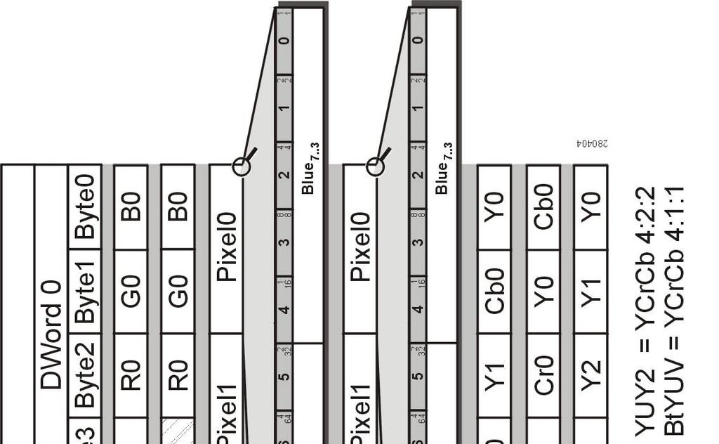
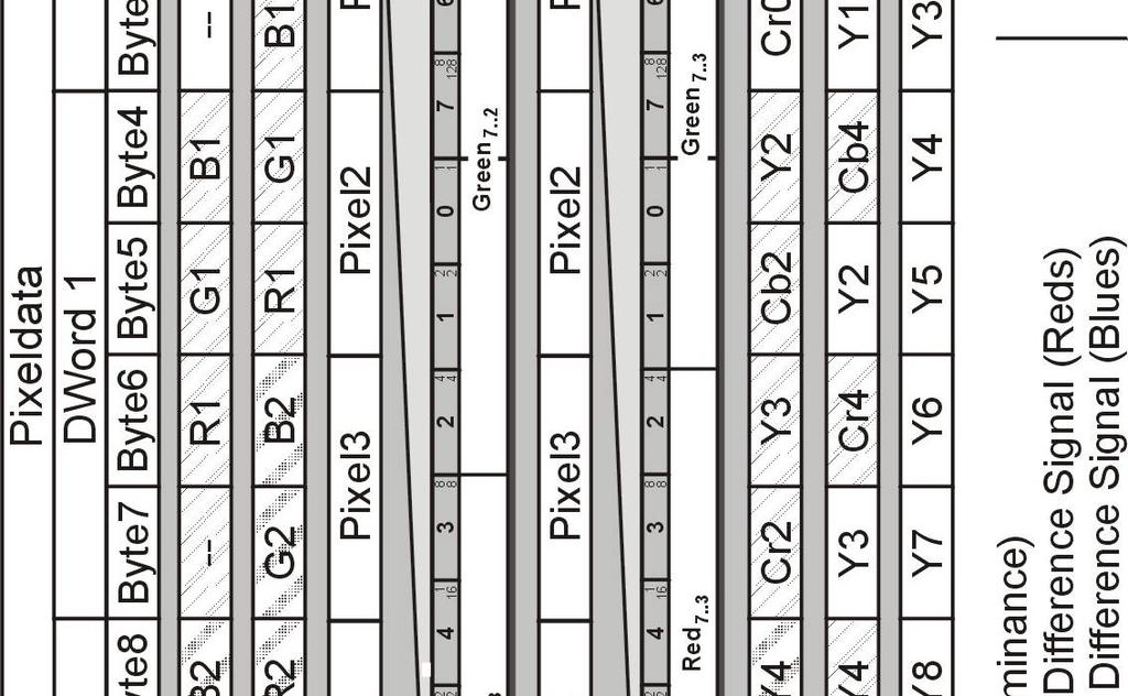
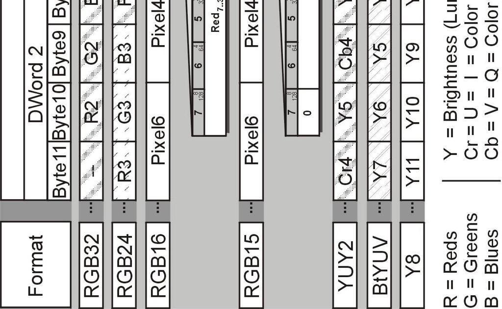
150 pcigrabber-4plus/express Figure 56: Color Format of the pcigrabber-4plus/express 148 PHYTEC Messtechnik GmbH 2016 L-556e_8
151 Driver Software Now the format of an image to be digitized, is exactly defined. The framegrabber must now be instructed where and how to store the data of the image in the memory. The Windows driver reserves an image memory space, in which the image is placed. How much memory will be used? This will be calculated from the size of the image (number of pixels) and the required number of bytes per pixel (color depth): Memory requirements per field = hsize. vsize. pixel size [byte] The value pixel size can be depicted from Table 14. For the format YUV2 and BtYUV it must be considered that 2 or 8 pixels are combined logically and that the resolution of the image is selected correspondingly. The value calculated for the required region of memory is valid for one field (even or odd). These values must be added if a frame is required Format pixel size [Byte] RGB32 4 RGB24 3 RGB16, RGB15 2 YUY2 4 Byte per 2 pixel BtYUV 12 Byte for 8 pixel Y8 1 Table 14: Required Memory Space of One Pixel for the Different Modi Programming Manual PHYTEC Messtechnik GmbH 2016 L-556e_8 149
152 pcigrabber-4plus/express If whole frames are required, because the resolution should be more than 288 lines, the framegrabber can be instructed to store the frame in one single memory region. The framegrabber automatically will interlace the two fields. If this option is required, ninterlaced is set to 1. Finally the type of image capture is described: With nsingleshot = 0 the framegrabber is instructed to capture continuously. That means, that after the start of the capture process, informations are stored in the memory in real time (up to 50 fields per sec.). In field mode (ninterlaced = 0) the information is stored to one memory region (20 ms), then to the other region (another 20 ms) alternatingly. This means, that each field memory region is not accessed by the framegrabber at least for 20 ms. For frame mode (ninterlaced = 1) the framegrabber stores continuously to the common memory, 20 ms the odd and then 20 ms the even lines. During the processing of the image data, it might be disturbing that the framegrabber is writing new data to the same region, and a mismatch might occur for fast moving objects. In this case a stop-and-go operation is recommended, or capturing the frames to separate memory regions which are processed alternatingly (ninterlace=0) nsingleshot = 1 has the effect that only one single capture takes place. Two fields are captured (one odd, one even) or one entire frame. The user can capture the images and with repeated starts new data are stored in the memory. This mode of operation is recommended, if only occasionally images are captured and no real time application is required. In any case, if continuous or single shot grabbing is used: Set_Image() configures, how the image is recorded. Grabbing is not started with this function but with the instruction Start_Grabber() (see description below). 150 PHYTEC Messtechnik GmbH 2016 L-556e_8
153 Driver Software ❸ Start Capture void Start_Grabber(WORD ndevno); The function Start_Grabber() starts capturing with the device specified by ndevno. The result will be digitization with the beginning of the next available image. If continuous mode was selected, then one image after the other will be captured until the instruction Stop_Grabber() is called. For single shot operation digitization is finished after one complete image. When does the first digitization take place? The driver handles whole frames. Always even/odd image combinations are evaluated. The timing will thus depend on the desired field and the field applied at the video input at start up time. We have to distinguish the following cases: (1) An even-field is requested for capturing a) At the input an even-field is in progress Since the image just in progress can not be captured anymore (the beginning is missing), the rest of the even field and the next odd field will pass before capture will start. So the next complete even field will be digitized. The delay from the start instruction to the beginning of the capture process will be less than 40 ms. b) At the input an odd field is in progress The even field following the odd field will be digitized. Maximum delay time: 20 ms. (2) An odd-field is requested for capturing a) At the input an even field is in progress Since the driver evaluates even fields first, the rest of the incomplete even field and the following odd field will pass, Programming Manual PHYTEC Messtechnik GmbH 2016 L-556e_8 151
154 pcigrabber-4plus/express until the framegrabber will synchronize with the next even field. Now the starting odd field will be digitized. The maximum delay will be less than 60 ms. b) At the input an odd field is in progress First the incomplete odd field will pass and then the framegrabber will be synchronized with the following even field, and will start the subsequent odd field. The maximum delay will be less than 40 ms. ❸ Stop Capture void Stop_Grabber(WORD ndevno); This routine Stop_Grabber aborts the capture process. The transfer of data will be cancelled immediately and the image might be incomplete. Caution: Stop_Grabber must be called also for capturing in single shot mode (nsingleshot = 1 in Set_Image ) when operation is stopped automatically. The Grabber is locked (paused), until Stop_Grabber is called. Thereafter a new single shot can be initiated with Start_Grabber. 152 PHYTEC Messtechnik GmbH 2016 L-556e_8
.")
155 Driver Software ❸ Get Capture Status WORD Data_Present(WORD ndevno); return value: shows status of capture process (4-bit - values 0-15) The function Data_Present indicates if an even or odd image is stored in the memory. In the separate bits of the return value the status for continuous or single shot operation of the digitization is coded (see Figure 57). Bit 0 and 2 indicate, that an even image was captured, bit 1 and 3 represent an odd image. Bits 0 and 1 toggle their state with each beginning of an even or odd image resp.. For continuous capturing, this indicates when the content of the corresponding memory region is written completely with a new image s data. Each alteration of the status (0 to 1 and 1 to 0) indicates, that a new field was captured. Figure 57: Return Values of Data_Present Bits 2 and 3 are set to 1, as soon as an even or odd image was completely captured. Those bits are used, in case only one image is to be captured (single-shot, defined by Set_Image ). The bits remain set until a new capture process is started. Programming Manual PHYTEC Messtechnik GmbH 2016 L-556e_8 153
Grabber-4plus. Hardware Manual. Edition April A product of a PHYTEC Technology Holding company
 Grabber-4plus Hardware Manual Edition April 2004 A product of a PHYTEC Technology Holding company pcigrabber-4plus In this manual are descriptions for copyrighted products that are not explicitly indicated
Grabber-4x4. Hardware-Manual. Edition January A product of a PHYTEC Technology Holding company
 Grabber-4x4 Hardware-Manual Edition January 2009 A product of a PHYTEC Technology Holding company pcigrabber-4x4 In this manual are descriptions for copyrighted products that are not explicitly indicated
egrabber-4plus Hardware Manual Edition June 2004 A product of a PHYTEC Technology Holding company
 egrabber-4plus Hardware Manual Edition June 2004 A product of a PHYTEC Technology Holding company egrabber-4plus In this manual are descriptions for copyrighted products that are not explicitly indicated
DT3130 Series for Machine Vision
 Compatible Windows Software DT Vision Foundry GLOBAL LAB /2 DT3130 Series for Machine Vision Simultaneous Frame Grabber Boards for the Key Features Contains the functionality of up to three frame grabbers
AI-1204Z-PCI. Features. 10MSPS, 12-bit Analog Input Board for PCI AI-1204Z-PCI 1. Ver.1.04
 10MSPS, 12-bit Analog Board for PCI AI-1204Z-PCI * Specifications, color and design of the products are subject to change without notice. This product is a PCI bus-compliant interface board that expands
picasso TM 3C/3Cpro series Datasheet picasso TM 3C/3Cpro models Key features
 Datasheet picasso TM 3C/3Cpro models Key features high performance RGB framegrabber with excellent linearity and very low noise levels 3C models: two multiplexed channels with each 3 x 8 bits RGB video
Industriefunkuhren. Technical Manual. IRIG-B Generator-Module for analogue / digital Signals of Type: IRIG-B / IEEE C / AFNOR NF S87-500
 Industriefunkuhren Technical Manual IRIG-B Generator-Module for analogue / digital Signals of Type: IRIG-B / IEEE C37.118 / AFNOR NF S87-500 Module 7628 ENGLISH Version: 02.01-06.03.2013 2 / 20 7628 IRIG-B
DT3162. Ideal Applications Machine Vision Medical Imaging/Diagnostics Scientific Imaging
 Compatible Windows Software GLOBAL LAB Image/2 DT Vision Foundry DT3162 Variable-Scan Monochrome Frame Grabber for the PCI Bus Key Features High-speed acquisition up to 40 MHz pixel acquire rate allows
PCI Express JPEG Frame Grabber Hardware Manual Model 817 Rev.E April 09
 PCI Express JPEG Frame Grabber Hardware Manual Model 817 Rev.E April 09 Table of Contents TABLE OF CONTENTS...2 LIMITED WARRANTY...3 SPECIAL HANDLING INSTRUCTIONS...4 INTRODUCTION...5 OPERATION...6 Video
AI-1664LAX-USB. Features. 100KSPS 16-bit Analog Input Unit for USB AI-1664LAX-USB 1. Ver.1.01
 100KSPS 16-bit Analog Unit for USB AI-1664LAX-USB * Specifications, color and design of the products are subject to change without notice. This product is a USB2.0-compliant analog input unit that extends
PCI Frame Grabber. Model 611 (Rev.D)
") SENSORAY CO., INC. PCI Frame Grabber Model 611 (Rev.D) July 2001 Sensoray 2001 7313 SW Tech Center Dr. Tigard, OR 97223 Phone 503.684.8073 Fax 503.684.8164 sales@sensoray.com www.sensoray.com Table of
SENSORAY CO., INC. PCI Frame Grabber Model 611 (Rev.D) July 2001 Sensoray 2001 7313 SW Tech Center Dr. Tigard, OR 97223 Phone 503.684.8073 Fax 503.684.8164 sales@sensoray.com www.sensoray.com Table of
P-2 Installing the monitor (continued) Carry out as necessary
 Carry out as necessary") P-2 Installing the monitor (continued) Carry out as necessary Using the monitor without the bezel MDT552S satisfies the UL requirements as long as it is used with the bezel attached. When using the monitor
P-2 Installing the monitor (continued) Carry out as necessary Using the monitor without the bezel MDT552S satisfies the UL requirements as long as it is used with the bezel attached. When using the monitor
USER S MANUAL (1/2) (Functions and connections)
 (Functions and connections)") English USER S MANUAL (1/2) (Functions and connections) WIDE PLASMA DISPLAY P42VCA30W/P42VCA30E WITH OPTIONAL VIDEOBOARD (P-TE1100/P-TE1110/P-TE1120/P-TE1130) HE4VS01W/HE4VS01E WITH OPTIONAL VIDEOBOARD
English USER S MANUAL (1/2) (Functions and connections) WIDE PLASMA DISPLAY P42VCA30W/P42VCA30E WITH OPTIONAL VIDEOBOARD (P-TE1100/P-TE1110/P-TE1120/P-TE1130) HE4VS01W/HE4VS01E WITH OPTIONAL VIDEOBOARD
DUAL/QUAD DISPLAY CONTROLLER Operation Manual
 DUAL/QUAD DISPLAY CONTROLLER Operation Manual Model PXD524 MicroImage Video Systems division of World Video Sales Co., Inc PO Box 331 Boyertown, PA 19512 Phone 610-754-6800 Fax 610-754-9766 sales@mivs.com
MultiView T4 / T5 Transmitter
 MultiView T4 / T5 Transmitter Quick Reference & Setup Guide Magenta Research 128 Litchfield Road, New Milford, CT 06776 USA (860) 210-0546 FAX (860) 210-1758 www.magenta-research.com PN 5310188-01, Rev
Evaluation Board for CS4954/55
 Evaluation Board for CS4954/55 Features l Demonstrates recommended layout and grounding practices l Supports both parallel and serial digital video input l On-board test pattern generation l Supports NTSC/PAL
PicoScope 2000 Series PC Oscilloscopes
 PicoScope 2000 Series PC Oscilloscopes User guide I PicoScope 2000 Series User Guide Table of Contents 1 Introduction...2...2 1 Overview...2 2 Safety symbols...3 3 Safety warning...3 4 FCC notice 5 CE
LTC 113x & LTC123x FlexiDome Series Fixed Dome Cameras
 LTC 113x & LTC123x FlexiDome Series Fixed Dome Cameras Eng Installation Instructions F D E NL I IMPORTANT SAFEGUARDS 1. Read Instructions All the safety and operating instructions should be read before
Vorne Industries. 87/719 Analog Input Module User's Manual Industrial Drive Itasca, IL (630) Telefax (630)
 Telefax (630)") Vorne Industries 87/719 Analog Input Module User's Manual 1445 Industrial Drive Itasca, IL 60143-1849 (630) 875-3600 Telefax (630) 875-3609 . 3 Chapter 1 Introduction... 1.1 Accessing Wiring Connections
Vorne Industries 87/719 Analog Input Module User's Manual 1445 Industrial Drive Itasca, IL 60143-1849 (630) 875-3600 Telefax (630) 875-3609 . 3 Chapter 1 Introduction... 1.1 Accessing Wiring Connections
DIGITAL SWITCHERS 2100 SERIES
 DIGITAL SWITCHERS 00 SERIES HIGH PERFORMANCE DIGITAL ROUTING OPERATORS MANUAL Includes Module and Frame Information for: AUDIO DAS- DAS-88 DAS-66 VIDEO DVS- DVS-8 DVS-6 DVM-66 DVS-66 SIGMA ELECTRONICS,
Uni700 LCD Controller
 Landmark Technology Inc. Uni700 LCD Controller For TFT LCDs with Resolution up to 1,920 x 1,200 (Version A) January 27, 2009 1 1. Introduction The Uni700 controller board is designed for LCD panels of
FLAT DISPLAY TECHNOLOGY
 15.0 Open Frame Monitor Model Number: LOF1506xx This product is RoHS compliant SPEC No.: SAS-1008002 Version: 0.0 Issue Date: September 6, 2010 1. Introduction: 1.1 About the Product The LOF1506xx 15.0
Industriefunkuhren. Technical Manual. OEM Sync-Module FE1000 (IRIG-B) ENGLISH
 ENGLISH") Industriefunkuhren Technical Manual OEM Sync-Module FE1000 (IRIG-B) ENGLISH Version: 07.02-24.03.2014 2 / 19 FE1000 IRIG-B Synchronisation - V07.02 IMPORTANT NOTES Version Number (Firmware / Manual) THE
Industriefunkuhren Technical Manual OEM Sync-Module FE1000 (IRIG-B) ENGLISH Version: 07.02-24.03.2014 2 / 19 FE1000 IRIG-B Synchronisation - V07.02 IMPORTANT NOTES Version Number (Firmware / Manual) THE
DCT 532. Industrial Pressure Transmitter with i²c interface. Stainless Steel Sensor
 Industrial Pressure Transmitter with i²c interface Stainless Steel Sensor Accuracy according to IEC 60770: standard: ± 0. % FSO option: ± 0. % FSO Nominal pressure from 0... 00 mbar up to 0... 00 bar Digital
AES-402 Automatic Digital Audio Switcher/DA/Digital to Analog Converter
 Broadcast Devices, Inc. AES-402 Automatic Digital Audio Switcher/DA/Digital to Analog Converter Technical Reference Manual Broadcast Devices, Inc. Tel. (914) 737-5032 Fax. (914) 736-6916 World Wide Web:
USERS GUIDE MCX-HTS. HDMI to 3G SDI Converter. Manual Number:
 USERS GUIDE MCX-HTS HDMI to 3G SDI Converter i Manual Number: 151226 SAFETY INSTRUCTIONS Please review the following safety precautions. If this is the first time using this model, then read this manual
MDS 100 LINE MULTIPLIER, SCAN CONVERTER AND SWITCHER
 5 INPUTS WITH ASSOCIATED AUDIO 2 SIMULTANEOUS CONVERSIONS: PC/TV AND TV/PC WIDE RANGE OF CORRECTIONS AND ADJUSTMENTS MUTE AUDIO FUNCTION ON BOTH OUTPUTS OSD ON BOTH OUTPUTS MAINTENANCE OF PRESETTINGS POSSIBILITY
Owner s Manual. multiswitch Firmware-Version 1.06 OS- Version 1.02
 Owner s Manual multiswitch 1.41 Firmware-Version 1.06 OS- Version 1.02 The information contained in this manual is subject to change without prior notice. All rights reserved. Current as of: Juli 19 th
AI-1616L-LPE. Features. High-precision Analog input board (Low Profile size) for PCI Express AI-1616L-LPE 1. Ver.1.02 Ver.1.01
 for PCI Express AI-1616L-LPE 1. Ver.1.02 Ver.1.01") High-precision Analog input board (Low Profile size) for PCI Express AI-1616L-LPE This product is a multi-function, PCI Express bus-compliant interface board that incorporates high-precision 16-bit analog
High-precision Analog input board (Low Profile size) for PCI Express AI-1616L-LPE This product is a multi-function, PCI Express bus-compliant interface board that incorporates high-precision 16-bit analog
Model 5250 Five Channel Digital to Analog Video Converter Data Pack
 Model 5250 Five Channel Digital to Analog Video Converter Data Pack E NSEMBLE D E S I G N S Revision 3.1 SW v2.0.1 This data pack provides detailed installation, configuration and operation information
CAPTURE CAPTURE. VERSiON 1.2. Specialists in Medical. Digital Imaging Solutions
 CAPTURE Add-on module for capturing images from analog video sources CAPTURE anything to DICOm VERSiON 1.2 Specialists in Medical Digital Imaging Solutions iq-capture Connect any medical device to your
Advantech Proudly Presents Professional Monitor Series
 Advantech Proudly Presents Professional Monitor Series Model PN-E421 P/N: DSD-420N-70FH-S1E The 42" Class (42-1/16" Diagonal) LCD monitor offers exceptionally high image quality and reliability for use
PCIe-FRM21. User s Manual
 PCIe-FRM21 User s Manual Windows, Windows2000, Windows NT and Windows XP are trademarks of Microsoft. We acknowledge that the trademarks or service names of all other organizations mentioned in this document
DT9834 Series High-Performance Multifunction USB Data Acquisition Modules
 DT9834 Series High-Performance Multifunction USB Data Acquisition Modules DT9834 Series High Performance, Multifunction USB DAQ Key Features: Simultaneous subsystem operation on up to 32 analog input channels,
3G/HD/SD-SDI to HDMI Converter
 3G/HD/SD-SDI to HDMI Converter Model #: 3G/HD/SD-SDI to HDMI Converter 2010 Avenview Inc. All rights reserved. The contents of this document are provided in connection with Avenview Inc. ( Avenview ) products.
Software Analog Video Inputs
 Software FG-38-II has signed drivers for 32-bit and 64-bit Microsoft Windows. The standard interfaces such as Microsoft Video for Windows / WDM and Twain are supported to use third party video software.
grabbmodul-4 Hardware Manual Edition February 2005
 grabbmodul-4 Hardware Manual Edition February 2005 A product of a PHYTEC Technology Holding company grabbmodul-4 In this manual are descriptions for copyrighted products that are not explicitly indicated
Modular DAA with 2/4 Wire Convertor. XE0002D Block Diagram
 XE0002D August 2005 Modular DAA with 2/4 Wire Convertor Description The XE0002D is a compact DAA module designed for applications requiring voice, data or fax transfer. It complies with FCC Part 68 rules
Displays Open Frame Monitor Model Number: AND-TFT-150Bxx
 Displays 15.0 Open Frame Monitor Model Number: AND-TFT-150Bxx The AND-TFT-150Bxx 15.0 Open Frame Monitor series are rugged, high performance Industrial LCD Monitors, designed for commercial and industrial
VGA to DVI Extender over Fiber SET
 VGA to DVI Extender over Fiber SET Model #: FO-VGA-DVI 2011 Avenview Inc. All rights reserved. The contents of this document are provided in connection with Avenview Inc. ( Avenview ) products. Avenview
(1) (2) (3) Bedienungs- und Montageanleitung. Safety instructions. Structure of the device
 (2) (3) Bedienungs- und Montageanleitung. Safety instructions. Structure of the device") 3 x cinch/s-video socket Order no. 33 1532 xx USB/3.5 mm audio socket Order no. 33 1539 xx VGA socket Order no. 33 1540 xx VGA socket with screw-in lift terminals Order no. 33 1541 xx High definition socket
3 x cinch/s-video socket Order no. 33 1532 xx USB/3.5 mm audio socket Order no. 33 1539 xx VGA socket Order no. 33 1540 xx VGA socket with screw-in lift terminals Order no. 33 1541 xx High definition socket
TVAC20000 User manual
 TVAC20000 User manual Version 01/2010 Original English user manual. Keep for future use. 10 Introduction Dear Customer, Thank you for purchasing this product. This product meets the requirements of the
TR6102HD HDTV/DVD/COMPONENT VIDEO TO RGBHV TRANSCODER USER S GUIDE
 MANUAL PART NUMBER: 400-0031-003 PRODUCT REVISION: 1 HDTV/DVD/COMPONENT VIDEO TO RGBHV TRANSCODER USER S GUIDE INTRODUCTION Thank you for your purchase of the Transcoder. We are certain that you will find
Model /29S RF Splitter
 Instruction Manual Model 1584-29/29S RF Splitter March 2013, Rev. 0 LNB VOLTAGE A B MODEL 1584 COMBINER CROSS TECHNOLOGIES INC. GND+DC ON Data, drawings, and other material contained herein are proprietary
HDBaseT EXTENDER B-540-EXT-230-RS INSTALLATION MANUAL
 EXTENDER B-540-EXT-230-RS INSTALLATI MANUAL IMPORTANT SAFETY INSTRUCTIS To reduce the risk of fire or electric shock, read and follow all instructions and warnings in this manual. Keep this manual for
INSTRUCTION MANUAL MODEL 2710 SUBCARRIER DEMODULATOR
 INSTRUCTION MANUAL MODEL 2710 SUBCARRIER DEMODULATOR Data, drawings, and other material contained herein are proprietary to Cross Technologies, Inc., and may not be reproduced or duplicated in any form
Model :UVC-S100 (Universal Video Converter)
") Customer : General Specification V1.0 Model :UVC-S100 (Universal Video Converter) Revised : 25 th October, 2012 OPHIT Co., Ltd. 3F, Suntechnovil,5-27,Mangpo-Dong, Yeongtong-Gu, Suwon-City, Kyungki-Do,
Customer : General Specification V1.0 Model :UVC-S100 (Universal Video Converter) Revised : 25 th October, 2012 OPHIT Co., Ltd. 3F, Suntechnovil,5-27,Mangpo-Dong, Yeongtong-Gu, Suwon-City, Kyungki-Do,
Model 6010 Four Channel 20-Bit Audio ADC Data Pack
 Model 6010 Four Channel 20-Bit Audio ADC Data Pack Revision 3.1 SW v1.0.0 This data pack provides detailed installation, configuration and operation information for the Model 6010 Four Channel 20-bit Audio
Instruction Manual. SMS 8601 NTSC/PAL to 270 Mb Decoder
 Instruction Manual SMS 8601 NTSC/PAL to 270 Mb Decoder 071-0421-00 First Printing: November 1995 Revised Printing: November 1998 Contacting Tektronix Customer Support Product, Service, Sales Information
Model Number Structure
 Cycle Control Units CSM DS_E_7_1 Refer to Safety Precautions for All Power Controllers. Used in Combination with the to Enable High-precision Temperature Control Use cycle control to achieve power control
HDBaseT RECEIVER B-520-RX-230-IR INSTALLATION MANUAL
 HDBaseT RECEIVER B-520-RX-230-IR INSTALLATION MANUAL IMPORTANT SAFETY INSTRUCTIONS To reduce the risk of fire or electric shock, read and follow all instructions and warnings in this manual. Keep this
Document Part Number: Copyright 2010, Corelis Inc.
 CORELIS Low Voltage Adapter Low Voltage Adapter Boundary-Scan Interface User s Manual Document Part Number: 70398 Copyright 2010, Corelis Inc. Corelis, Inc. 12607 Hiddencreek Way Cerritos, CA 90703-2146
PRO-CoaxExt HDMI extender over Coaxial cable with bi-directional IR User s Guide
 HDMI extender over Coaxial cable with bi-directional IR User s Guide Transmitter Receiver Made in Taiwan Congratulations for owning a gofanco product. Our products aim to meet all your connectivity needs
PRO-ScalerV2HD VGA to HDMI & Audio Scaler Converter. User s Guide. Made in Taiwan
 VGA to HDMI & Audio Scaler Converter User s Guide Made in Taiwan Congratulations for owning a gofanco product. Our products aim to meet all your connectivity needs wherever you go. Have fun with our products!
Electro Magnetic Compatibility (EMC) Warning. Important notes for users in the U.K. FCC declaration. Caution. Fuse
 Warning. Important notes for users in the U.K. FCC declaration. Caution. Fuse") Warning: to prevent fire or shock hazard, do not expose camera or monitor to rain or moisture. The lightning flash with arrowhead symbol, within a triangle, is intended to alert the user to the presence
Warning: to prevent fire or shock hazard, do not expose camera or monitor to rain or moisture. The lightning flash with arrowhead symbol, within a triangle, is intended to alert the user to the presence
6.4 Chassis Monitor Model Number: LCM0642xx. SPEC No.: SAS Version: 0.0 Issue Date: April 16, Introduction:
 6.4 Chassis Monitor Model Number: LCM0642xx This product is RoHS compliant SPEC No.: SAS-0908003 Version: 0.0 Issue Date: April 16, 2010 1. Introduction: 1.1 About the Product The LCM0642xx 6.4 Chassis
AD12-16U(PCI)EV. Features. High-Speed Analog Input Board for PCI AD12-16U(PCI)EV 1. Ver.1.01
EV. Features. High-Speed Analog Input Board for PCI AD12-16U(PCI)EV 1. Ver.1.01") High-Speed Analog Input Board for PCI AD2-6U(PCI)EV * s, color and design of the products are subject to change without notice. This product is PCI-compliant interface boards that convert analog input
High-Speed Analog Input Board for PCI AD2-6U(PCI)EV * s, color and design of the products are subject to change without notice. This product is PCI-compliant interface boards that convert analog input
Trusted 40 Channel Analogue Input FTA
 PD-T8830 Trusted Trusted 40 Channel Analogue Input FTA Product Overview The Trusted 40 Channel Analogue Input Field Termination Assembly (FTA) T8830 is designed to act as the main interface between a field
PRODUCT NO.: PT-L6600L/L6510L PRODUCT NAME: BriteOptic LCD Projectors
 PRODUCT NO.: PRODUCT NAME: s MAJOR FEATURES Ultrabright 4200 ANSI lumens (PT-L6510L) Ultrabright 3600 ANSI lumens (PT-L6600L) New BriteOptic technology and UHM lamps A wide variety of optional lenses True
MAX11503 BUFFER. Σ +6dB BUFFER GND *REMOVE AND SHORT FOR DC-COUPLED OPERATION
 19-4031; Rev 0; 2/08 General Description The is a low-power video amplifier with a Y/C summer and chroma mute. The device accepts an S-video or Y/C input and sums the luma (Y) and chroma (C) signals into
MaxView Cinema Kit Quick Install Guide
 SYSTEM SETUP The MaxView will work at any of the following display settings: INSTALLATION MaxView Cinema Kit Quick Install Guide Step 1 - Turn off your computer. Disconnect your monitor s VGA cable from
ACCESSORIES MANUAL PART NUMBER: PRODUCT REVISION: 1 PNP202. Interconnect Box USER'S GUIDE
 MANUAL PART NUMBER: 400-0109-001 PRODUCT REVISION: 1 PNP202 Interconnect Box USER'S GUIDE INTRODUCTION Your purchase of the PNP202 Interconnect Box is greatly appreciated. We are sure you will find it
DA1931CT/ TP to Video + Audio Receiver
 / TP to Video + Audio Receiver Welcome! We greatly appreciate your purchase of the Twisted Pair to Video + Audio Receiver. We are sure you will find it reliable and simple to use. Superior performance
User Manual PS-684. HDBaseT Extender Kit 70m. All Rights Reserved. Version: UHBT70P_2016V1.2
 User Manual PS-684 All Rights Reserved Version: UHBT70P_2016V1.2 Preface Read this user manual carefully before using this product. Pictures shown in this manual is for reference only, different model
OPERATING MANUAL. DMX LED Current Dimmer 5004A-EP Mk2
 OPERATING MANUAL DMX LED Current Dimmer 5004A-EP Mk2 (C) SOUNDLIGHT 1996-2006 * ALL RIGHTS RESERVED * NO PART OF THIS MANUAL MAY BE REPRODUCED, DUPLICATED OR USED COMMERCIALLY WITHOUT THE PRIOR WRITTEN
Model 1421 Distribution Amplifier
 Model 1421 Distribution Amplifier Installation and Operating Instructions The 1421 Distribution Amplifier provides four independent, wide bandwidth outputs from one video input. The unit is color compatible
Interfaces and Sync Processors
 Interfaces and Sync Processors Kramer Electronics has a full line of video, audio and sync interfaces. The group is divided into two sections Format Interfaces and Video Sync Processors. The Format Interface
SEL-3405 High-Accuracy IRIG-B Fiber-Optic Transceiver
 SEL-3405 High-Accuracy IRIG-B Fiber-Optic Transceiver Accurate IRIG-B Over Fiber Optics Major Features and Benefits The SEL-3405 High-Accuracy IRIG-B Fiber-Optic Transceiver can send high-accuracy demodulated
VGA Extender over Single CAT 6 Cable with Audio Support. Model Extend both video and audio up to 1000 feet
 VGA Extender over Single CAT 6 Cable with Audio Support Model 103004 Extend both video and audio up to 1000 feet Utilize a Cat 6 cable instead of a bulky VGA cable Supports a local monitor and local speakers
USB Smart Power Sensor
 50Ω -30 dbm to +20 dbm, 1 MHz to 8000 MHz The Big Deal Fast measurement speed, 10 msec USB HID device compatible with 32/64 Bit operating systems Includes Measurement Application GUI (Graphical User Interface)
MKH 8060 Directional studio microphone
 MKH 8060 Directional studio microphone Instruction manual Contents Contents Important safety information... 2 The MKH 8060... 3 Delivery includes... 4 Product overview... 5 Putting the MKH 8060 into operation...
HDBaseT RECEIVER B-540-RX-330-IR INSTALLATION MANUAL
 HDBaseT RECEIVER B-540-RX-330-IR INSTALLATION MANUAL IMPORTANT SAFETY INSTRUCTIONS To reduce the risk of fire or electric shock, read and follow all instructions and warnings in this manual. Keep this
HDMI 1X4 Distribution Amplifier (Splitter)
") HDTrinity HDMI 1X4 Distribution Amplifier (Splitter) USER MANUAL Model No. SS04 DEAR CUSTOMER Thank you for purchasing this product. For optimum performance and safety, please read these instructions carefully
HDTrinity HDMI 1X4 Distribution Amplifier (Splitter) USER MANUAL Model No. SS04 DEAR CUSTOMER Thank you for purchasing this product. For optimum performance and safety, please read these instructions carefully
3GSDI to HDMI 1.3 Converter
 3GSDI to HDMI 1.3 Converter EXT-3GSDI-2-HDMI1.3 User Manual www.gefen.com ASKING FOR ASSISTANCE Technical Support: Telephone (818) 772-9100 (800) 545-6900 Fax (818) 772-9120 Technical Support Hours: 8:00
CLT-353R & CLT-353L CAMERA LINK TRANSLATOR. User s Manual. Document # , Rev 0.1, 4/19/2013 preliminary
 CLT-353R & CLT-353L CAMERA LINK TRANSLATOR User s Manual Document # 201201, Rev 0.1, 4/19/2013 preliminary Vivid Engineering 159 Memorial Drive, Suite F Shrewsbury, MA 01545 Phone 508.842.0165 Fax 508.842.8930
PRO-ScalerHD2V HDMI to VGA & Audio Scaler Converter. User s Guide. Made in Taiwan
 PRO-ScalerHD2V HDMI to VGA & Audio Scaler Converter User s Guide Made in Taiwan Congratulations for owning a gofanco product. Our products aim to meet all your connectivity needs wherever you go. Have
On-screen display signal strength meter Version 1.02
 OSD-SSM On-screen display signal strength meter Version 1.02 Copyright 2000 Intuitive Circuits, LLC D escription OSD-SSM is an on-screen display overlay board with analog to digital circuitry which continuously
HDBaseT RECEIVER B-520-RX-330-IR INSTALLATION MANUAL
 HDBaseT RECEIVER B-520-RX-330- INSTALLATION MANUAL IMPORTANT SAFETY INSTRUCTIONS To reduce the risk of fire or electric shock, read and follow all instructions and warnings in this manual. Keep this manual
Guide for installers. METTLER TOLEDO MultiRange System solution analog Ex1. Hazardous area. Safe area
 Guide for installers METTLER TOLEDO MultiRange System solution analog Ex1 Hazardous area Safe area System solution analog Ex1 Contents Contents Page 1 Safety precautions... 2 2 System overview... 3 2.1
SCALE & WEIGHT DISPLAYS
 The MICRO SERIES SCALE & WEIGHT DISPLAYS LARGE DIGIT MODELS Mighty-5S DPM MODELS Micro-S & Mighty-1S Mighty-1S Micro-S ELECTRO-NUMERICS, INC. Introduction The Electro-Numerics family of Digital Panel Meters
IRIG-B PTP Clock Converter Output Module Hardware Installation Manual
 IRIG-B PTP Clock Converter Output Module Hardware Installation Manual Kyland Technology Co., LTD. Publication Date: May 2012 Version: V1.2 Customer Service Hotline: (+8610) 88796676 FAX: (+8610) 88796678
User Guide. Video to VGA/HD Converter/Scaler DVI-3420a. Video to DVI Converter/Scaler DVI-3410a
 User Guide Video to VGA/HD Converter/Scaler DVI-3420a Video to DVI Converter/Scaler DVI-3410a TABLE OF CONTENTS SECTION PAGE PRODUCT SAFETY... 1 PRODUCT LIABILITY.... 1 1.0 INTRODUCTION.... 2 2.0 SPECIFICATIONS....
32 Channel CPCI Board User Manual
 0 Sections Page 1.0 Introduction 1 2.0 Unpacking and Inspection 1 3.0 Hardware Configuration 1 4.0 Board Installation 5 5.0 I/O Connections and the Front Panel 5 5.1 Front Panel Layout 5 5.2 Input and
System Interface Unit SIU-100/100T
 System Interface Unit /100T Since its introduction, the Digital Mixer has opened up an entirely new set of opportunities for affordable PA and sound-recording applications. Recognizing the ever-increasing
PRO-HDMI2HD. HDMI to SDI/3G-HD-SD Converter. User Manual. Made in Taiwan
 PRO-HDMI2HD HDMI to SDI/3G-HD-SD Converter User Manual Made in Taiwan rev.1008 103 Quality Circle, Suite 210 Huntsville, Alabama 35806 Tel: (256) 726-9222 Fax: (256) 726-9268 Email: service@pesa.com Safety
Pablo II. The Picasso IV video-encoder. Manual. 18 August Copyright c 1997 Village Tronic Marketing GmbH Mühlenstraße Sarstedt Germany
 Pablo II The Picasso IV video-encoder Manual 18 August 1997 Copyright c 1997 Village Tronic Marketing GmbH Mühlenstraße 2 31157 Sarstedt Germany Technical Hotline: Tel. +49 (0)5066 / 7013-10 FAX: Tel.
Kramer Electronics, Ltd. USER MANUAL. Model: FC Analog Video to SDI Converter
 Kramer Electronics, Ltd. USER MANUAL Model: FC-7501 Analog Video to SDI Converter Contents Contents 1 Introduction 1 2 Getting Started 1 3 Overview 2 4 Your Analog Video to SDI Converter 3 5 Using Your
Winmate Communication INC.
 20.1 Military Grade Display Model: R20L100-RKA2ML User s Manual Winmate Communication INC. May, 2011 1 IMPORTANT SAFETY INSTRUCTIONS Please read these instructions carefully before using the product and
PRODUCT NO.: PT-L735NT PRODUCT NAME: Ultra Portable Wireless LCD Projector
 PRODUCT NO.: PRODUCT NAME: Ultra Portable Wireless LCD Projector MAJOR FEATURES Bright - High 2600 ANSI lumens brightness Easy wireless presentations - Easy-to-use settings - Useful Live mode - PC-free
I N S T R U C T I O N D A T A
 I N S T R U C T I O N D A T A RFL (C37.94) Fiber Service Unit Single Mode 108015-1 RS-449 108015-2 V.35 108015-3 G.703 108015-4 X.21 108015-5 E1 Multimode 107460-1 RS-449 107460-2 V.35 107460-3 G.703 107460-4
Operating instructions Electronic preset counter Type series 717
 Operating instructions Electronic preset counter Type series 717 1. Description 5.98.3_gb 6-digit adding/subtracting counter with two presets Very bright 8mm high LED display Counting and preset range
AES-404 Digital Audio Switcher/DA/Digital to Analog Converter
 Broadcast Devices, Inc. AES-404 Digital Audio Switcher/DA/Digital to Analog Converter Technical Reference Manual Broadcast Devices, Inc. Tel. (914) 737-5032 Fax. (914) 736-6916 World Wide Web: www.broadcast-devices.com
PicoScope PC Oscilloscopes. User's Guide. ps2203.en r4 Copyright Pico Technology Limited. All rights reserved.
 PicoScope 2203 PC Oscilloscopes User's Guide PicoScope 2203 User's Guide I Contents 1 Welcome...1 2 Introduction...2 1 Using this guide 2 Safety symbols 3 Safety warning 4 FCC notice 5 CE notice...2...2...3...4...4...5
VGA Extender SRN. EXT-VGA-141SRN. User Manual
 VGA Extender SRN EXT-VGA-141SRN User Manual www.gefen.com ASKING FOR ASSISTANCE Technical Support: Telephone (818) 772-9100 (800) 545-6900 Fax (818) 772-9120 Technical Support Hours: 8:00 AM to 5:00 PM
TBC & Matrix Switcher TBC-5000 Instruction Manual
 TBC & Matrix Switcher TBC-5000 Instruction Manual www.datavideo-tek.com Rev 150509 1 Contents Warnings and Precautions... 3 Warranty... 4 Disposal... 4 Packing List... 4 TBC-5000 Features... 4 Product
SK2002DA SIDEKICKER 1-IN, 2-OUT VGA-UXGA DISTRIBUTION AMPLIFIER CABLE USER S GUIDE DISTRIBUTION AMPLIFIERS
 MANUAL PART NUMBER: 400-0152-001 PRODUCT REVISION: 0 SK2002DA SIDEKICKER 1-IN, 2-OUT VGA-UXGA DISTRIBUTION AMPLIFIER CABLE USER S GUIDE TABLE OF CONTENTS Page PRECAUTIONS / SAFETY WARNINGS...2 GENERAL...2
VPS1 Installation Manual
 1-512-756-1678 VPS1 Installation Manual VPS1 Sender (Remote Unit) VPS1 Viewer (Local Unit) Contents Introduction...2 Features...2 Packing Checklist...2 The Connection Layout of VPS1...2 Certificate...2
User Manual MODEL: KKF1500-PCAP. True FLAT P-CAP LCD Monitor. Installation Guide. 15 True FLAT P-CAP Touch LCD Monitor
 True FLAT P-CAP LCD Monitor User Manual Installation Guide 15 True FLAT P-CAP Touch LCD Monitor MODEL: KKF1500-PCAP i-tech Company LLC TOLL FREE: (888) 483-2418 EMAIL: info@itechlcd.com WEB: www.itechlcd.com
User Manual MODEL: KK1500-TR. Touch Display LCD Monitor. Installation Guide. 15 Resistive Touch LCD Monitor
 Touch Display LCD Monitor User Manual Installation Guide 15 Resistive Touch LCD Monitor MODEL: KK1500-TR i-tech Company LLC TOLL FREE: (888) 483-2418 EMAIL: info@itechlcd.com WEB: www.itechlcd.com User
AD16-16U(PCI)EV. Features. High-Speed & Resolution Analog Input Board for PCI AD16-16U(PCI)EV 1. Ver.1.02
EV. Features. High-Speed & Resolution Analog Input Board for PCI AD16-16U(PCI)EV 1. Ver.1.02") High-Speed & Resolution Analog Input Board for PCI * Specifications, color and design of the products are subject to change without notice. This product is PCI-compliant interface boards that convert analog
High-Speed & Resolution Analog Input Board for PCI * Specifications, color and design of the products are subject to change without notice. This product is PCI-compliant interface boards that convert analog