DISPOSAL... 4 CHAPTER
|
|
|
- Richard Baldwin
- 5 years ago
- Views:
Transcription
1
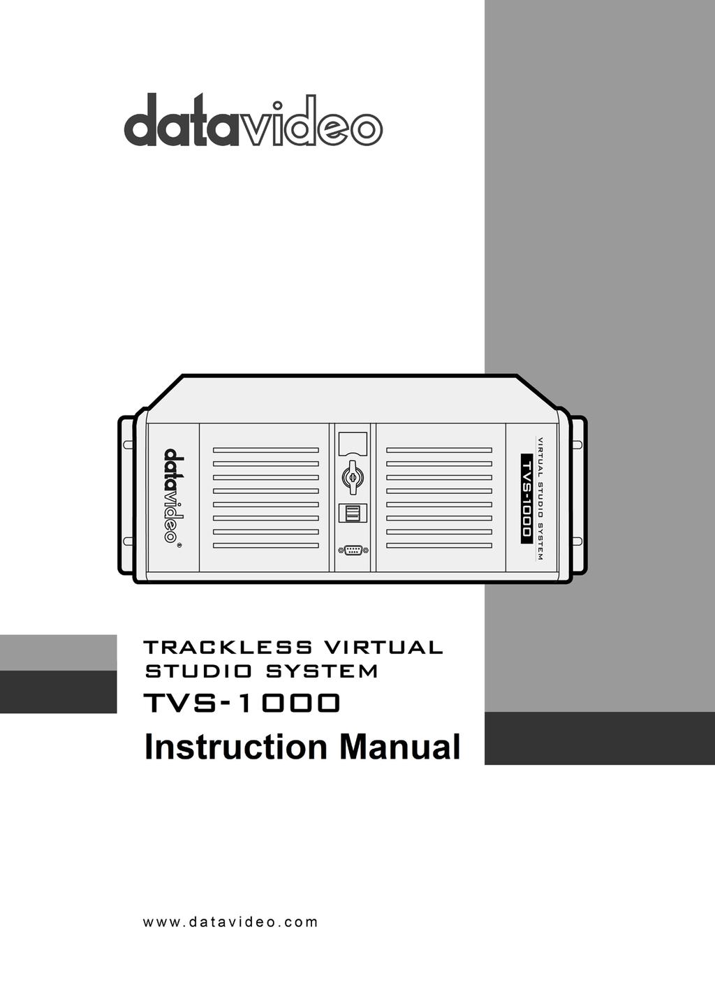
2 Table of Contents WARRANTY... 4 STANDARD WARRANTY... 4 TWO YEAR WARRANTY... 4 DISPOSAL... 4 CHAPTER 1 OVERVIEW FEATURES... 5 CHAPTER 2 TVS-1000 TRACKLESS VIRTUAL STUDIO SETUP SYSTEM REQUIREMENT CONNECTIONS Front Panel Back Panel Input/Output Card Options REMOVABLE HARD DISK INSTALLATION SYSTEM DIAGRAM TVS-1000 AUX CARD Introduction Installation Specification RMC-220 REMOTE CONTROLLER Control Panel Overview Main Unit - Rear Panel Program and Preset rows Preview and Program Switching Downstream Keyers Function Keys Keyboard Backlight CHAPTER 3 STARTING TVS-1000 SOFTWARE PRODUCTION LIVE STILL TEXT EDIT VIRTUALSET MAKER RICH SITE SUMMARY (RSS) VIRTUALSET SHOP CONFIGURATION SHUTDOWN CHAPTER 4 VIRTUALSET MAKER FEATURES GETTING STARTED VIRTUALSET MAKER TOUR USE CUSTOMIZED VIRTUALSET CHAPTER 5 PRODUCTION LIVE SCREEN TOOL BAR MULTI-VIEW AREA PROGRAM AND PREVIEW ROWS & FUNCTION SETTINGS input Main Switcher Switching between Preview and Program Views Downstream Keys VIRTUAL BACKGROUND EDITING Import
3 5.4.2 Placement Auto Play FILE MANAGEMENT ADDITIONAL MONITOR SUPPORT General Display Settings CHAPTER 6 CHROMA AND LUMA KEYS KEY SELECTION CHROMA KEY MATTE CONTROL TOLERANCE CORRECTION SPILL CORRECTION EDGE CORRECTION GARBAGE MASK POST CORRECTION CHAPTER 7 FAST CHROMAKEYING SIMPLE CHROMA KEY WIZARD CHAPTER 8 SOUND MIXER CHAPTER 9 MOTION CAPTURE SPECIFICATION CHAPTER 10 PROGRAM VIDEO STREAM CHAPTER 11 EXTERNAL KEYBOARDS RMC-220 FUNCTION KEYS Advanced Simple STANDARD WINDOWS KEYBOARD SHORTCUTS CHAPTER 12 SYSTEM RECOVERY CHAPTER 13 FREQUENTLY-ASKED QUESTIONS CHAPTER 14 SPECIFICATIONS SERVICE & SUPPORT Disclaimer of Product and Services The information offered in this instruction manual is intended as a guide only. At all times, Datavideo Technologies will try to give correct, complete and suitable information. However, Datavideo Technologies cannot exclude that some information in this manual, from time to time, may not be correct or may be incomplete. This manual may contain typing errors, omissions or incorrect information. Datavideo Technologies always recommend that you double check the information in this document for accuracy before making any purchase decision or using the product. Datavideo Technologies is not responsible for any omissions or errors, or for any subsequent loss or damage caused by using the information contained within this manual. Further advice on the content of this manual or on the product can be obtained by contacting your local Datavideo Office or dealer. 3

4 Warranty Standard Warranty Datavideo equipment is guaranteed against any manufacturing defects for one year from the date of purchase. The original purchase invoice or other documentary evidence should be supplied at the time of any request for repair under warranty. Damage caused by accident, misuse, unauthorized repairs, sand, grit or water is not covered by this warranty. All mail or transportation costs including insurance are at the expense of the owner. All other claims of any nature are not covered. Cables & batteries are not covered under warranty. Warranty only valid within the country or region of purchase. Your statutory rights are not affected. Two Year Warranty All Datavideo products purchased after 01-Oct qualify for a free one year extension to the standard Warranty, providing the product is registered with Datavideo within 30 days of purchase. For information on how to register please visit or contact your local Datavideo office or authorized Distributors Certain parts with limited lifetime expectancy such as LCD Panels, DVD Drives, Hard Drives are only covered for the first 10,000 hours, or 1 year (whichever comes first). Any second year warranty claims must be made to your local Datavideo office or one of its authorized Distributors before the extended warranty expires. Disposal For EU Customers only - WEEE Marking This symbol on the product indicates that it will not be treated as household waste. It must be handed over to the applicable take back scheme for the recycling of electrical and electronic equipment. For more detailed information about the recycling of this product, please contact your local Datavideo office. 4
5 Chapter 1 Overview TVS-1000 is a computer-based 2D trackless Virtual Studio System. It is a real-time production system with very high quality live chromakeying. TVS-1000 uses a single fixed camera and creates virtual cameras. This allows the director to zoom, pan and tilt the camera virtually within the set. Its innovative Virtual Set Maker enables users to create their own distinct, branded sets within minutes. Integrated into the system are tools to record the program output, broadcast live and stream over the Internet. 1.1 Features Varieties of System Inputs with Front Object Integration Cameras (number dependent on system configuration); Media (videos) two clips at the same time; Still images (bitmaps, text) two at the same time; Text two text compositions at the same time. Additional Media Features A Media Bin is a simple-to-use interface that makes it possible to gather all the media necessary for programme broadcast in one place; The media can be transferred from the bin to virtual players, used on air or as a source in virtual studios; The system has six bin tabs for four kinds of media: videos, still images, and text; Logo insertion on virtual scene. Virtual Background Features Load up to four virtual studio views simultaneously; Define movements of a virtual camera in different phases within every studio; Configurable Pan/Tilt/Zoom; Multi-Point Zoom; Virtual Studio backgrounds, which can be downloaded from Datavideo s virtual background database website; 30 free virtualsets available for downloads; CG-loaded backgrounds imported from external files, or edited by Still Text Editor. Media Previews Camera preview (one or two at a time, depending on system configuration); Media preview (two at a time); Still image preview (two at a time); Text preview (two at a time); Up to four virtual studio previews; PREVIEW presentation of the next element prepared for broadcast; PROGRAMME presentation of the current programme broadcast (system output); Previews on multiple monitors (if monitors are connected to a workstation, it is possible to obtain different preview configurations, even on three monitors); Real time streaming; Hard Drive (HD) Recording. 5
6 Supported Formats Format: 720p50 image resolution: 1280 x 720 Format: 720p60 image resolution: 1280 x 720 Format: 720p59.94 image resolution: 1280 x 720 Format: 1080i50 image resolution: 1920 x 1080 Format: 1080i60 image resolution: 1920 x 1080 Format: 1080i59.94 image resolution: 1920 x 1080 Format: 1080p25 image resolution: 1920 x 1080 Format: 1080p30 image resolution: 1920 x 1080 Format: 1080p29.97 image resolution: 1920 x 1080 Video Processing Formats Video processing: 4:4:4 16-bit floating-point internal processing; Inputs and outputs: YUV 4:2:2; Capture in output format: 4:2:0; Streaming: 4:2:2. Other Miscellaneous Features A Five-in-One System: Virtual Studio, Switcher, Character Generator, Recorder and Web Streaming Multi-Language Support; RMC-220 Remote Control; Audio Embedding Capability; Real time streaming; Hard Drive (HD) Recording; Virtualset Maker; Optional TVS AUX Card for an additional input. 6
 Keyboard HDMI camera x 1 or SDI camera")
7 Chapter System Requirement TVS-1000 Trackless Virtual Studio Setup Monitor x 1 (up to three monitors connected to choices of the HDMI x 1, DVI x 1, DisplayPort x 3) Keyboard HDMI camera x 1 or SDI camera with a converter x Connections Front Panel The front panel contains the RS-232 connection for operation with an external Datavideo RMC- 220 control panel. Access to the front panel is protected with a keyed door. This provides protection against the system being accidentally switched off or reset or the data disk being removed. It is recommended that the workstation should be positioned so as to ensure air flows reaching the front and the back panels. Fans providing appropriate system cooling are located behind the panels. The workstation case is designed to be mounted on a server rack and occupies a 4U space Back Panel Power Supply Socket Depending on the shipment destination and the user location, a power supply cord with a suitable plug will be supplied Power On/Off Switch Switches power On/Off 0 OFF 1 ON PS/2 Keyboard / Mouse combo port USB 2.0 ports Connection of an external standard USB keyboard and mouse USB 3.0 Ports (Blue) Connection of USB Wireless Dongle / Adapter IF ANY Please note that if you do not find the USB wireless dongle in the box, the TVS-1200 System Unit that you receive may already have a built-in wireless network card. 7
8 LAN (RJ-45) port Connection of the workstation to a computer network Input/Output Card Options Display Card (One of the following) Display card allows connection of two DVI-D ports, one HDMI output port or one DisplayPort. Note: It is recommended to connect production window (Monitor 1) to HDMI port. Display card allows connection of one DVI-I ports, one HDMI output port or three DisplayPorts. Virtu Card Virtu card allows connection of a single HDMI input/output pair and a mini phone jack for audio input. With both display and virtu SDI cards installed, it is thus possible to achieve different combinations of views on the monitors. For more information, please refer to Configuration Layout section. (MSI GTX 960) 8


9 2.3 Removable Hard Disk Installation How to Assemble 2.5" HDD in Removable Rack Warning: You must use TVS-1000 proprietary HDD and not any Datavideo HDR series or DN series. Avoid HOT PLUGGING during operation (while writing to and reading from the disk) because it may cause damage to the system and files. 1. Remove the two screws on the rear cover of the removable 2.5" HDD enclosure and manually pull out the PCB. 2. Tighten four screws to fasten 2.5" HDD on the PCB as shown in the diagram below. 3. Push the PCB with 2.5" HDD into the HDD enclosure. 4. Tighten the two screws of the rear cover of the removable 2.5" HDD enclosure. 5. Push the removable 2.5" HDD enclosure into the front slot of TVS-1000 system. 9

10 2.4 System Diagram 10

11 2.5 TVS-1000 AUX Card Introduction TVS Virtu AUX Card is designed primarily for powerpoint file input via HDMI port as well as for other applications such as media player or camera input. TVS AUX card can also be used in TVS TVS-1000 Virtu HDMI Card and Virtu AUX Card Mapping Table Card Type H/W Workable w/ Remark Version AUX Card 1.0 X HDMI Ver 1.0 H/W limited. 1.2 X HDMI Ver 1.2 H/W limited. Virtu HDMI Functional but with warning 1.3 messages 1.4 O Table 1: TVS-1000 Virtu HDMI Card and Virtu AUX Card Mapping Table Above table points out Virtu HDMI card H/W ver 1.0 & 1.2 cannot be workable with Virtu AUX card. Only Virtu HDMI card H/W version above 1.3 can work with Virtu AUX card Installation There are two models of motherboard used for TVS-1000 PC System: ASUS H87-PRO (white PCIe slot) and ASUS H97-PRO (black PCIe slot) ASUS H87-PRO Motherboard 1. Remove Wi-Fi card 2. Insert AUX card in the Wi-Fi card slot 3. For TVS-VIRTU HDMI Card Version 1.4, use the cable shown to the right to connect between TVS Virtu AUX card and TVS Virtu HDMI card ASUS H97-PRO Motherboard 1. Remove Wi-Fi card and insert it in the slot located between HDMI card and video card 2. Insert AUX card in the Wi-Fi card slot (PCIe) 3. For TVS-VIRTU HDMI Card Version 1.4, use the cable shown to the right to connect between TVS Virtu AUX card and TVS Virtu HDMI card The cable connection between TVS Virtu AUX card and TVS Virtu HDMI card is depicted in the diagram below. The location of the slot for the cable connection is circled in red as shown in the diagram on the left. Both cards should have the identical slot at the same location. 11
12 2.5.3 Specification TVS Virtu Aux Card Video Input HDMI x 1 Video Output Video Input Format HDMI x 1 (Preview without audio) P/29.97P/25P i/59.94i/50i P/59.94P/50P Audio Input Mini Phone Jack x 1 HDMI audio embedded 2.6 RMC-220 Remote Controller The RMC-220 is a cost effective remote controller designed specifically for the TVS-1000 Virtual Studio System. The RMC-220 interfaces with the TVS-1000 Virtual Studio System via an RS-232 interface. The RMC-220 gives the user switcher-style control of the TVS-1000 Virtual Studio System. There are several effects that the user can also control on the RMC-220, such as downstream keyers (DSK), logo insertion, and transition effects. In addition, the T-Bar gives the user the convenience to perform transitions between Preview (PVW) and Program (PGM). The RMC-220 has also been equipped with 10 function keys, which provide the user with the flexibility of manually assigning functions related to audio features, downstream keyer, delay, mix effect, media player functions and output effects to the 10 keys. The features are summarized as follows, A switcher style keyboard for direct TVS-1000 operation Clear key definitions Ten user-defined function keys, F1 to F10 and each of these function keys can be: Audio DSK General Mix Effect Media Output Capture Mute Capture Volume Input Mute Input Solo Input Volume Output Mute Output Volume Streaming Mute Streaming Volume Set Position Set Preview Set Rotation Set Scale Set Source Transition Cut Transition Fade Delay Import Studio Set AutoPlay Set Bus A Source Set Bus B Source Set Phase Set Speed Auto Play Loop Play Pause Play Select Stop Select Preview Select Program Transition Cross-Dissolve Transition Fade to Black Program/Preset Rows with buttons allowing the user to switch between CAM1, CAM2, ME1, ME2, ME3, ME4, Media1, Media2, Still1 and Still2 Three custom-set phase buttons for virtual camera lens zoom in/out Auto play button for automatic movement of the virtual camera T-Bar can be operated in one way or two way mode Take button to switch between PVW and PGM views FTB button fades the PGM view to a black screen Cross Dissolve button applies cross-dissolve transition effect to switching between PGM and PVW views 12

13 Two downstream keyers (DSK) with two corresponding knobs for assignment of DSK sources Cut and Fade buttons transition DSKs between PGM and PVW views Stream button triggers live video program streaming Capture function records the live video program Still Grab function captures the instantaneous video image RS-232 interface for communication between RMC-220 and TVS V DC input making the unit ideal for studio applications Bright LED lighting Control Panel Overview F1-F10 Function Keys F1 F10 Phase 3 Phase 3 selection CAM 1 Camera 1 view selection Auto Play Auto Play function *CAM 2 Camera 2 view selection Take Switch between PVW and PGM M/E 1 M/E 1 view selection FTB Fade PGM to Black M/E 2 M/E 2 view selection Cross Dissolve Cross dissolve transition effect M/E 3 M/E 3 view selection T-Bar Manual Transition M/E 4 M/E 4 view selection STM Program Streaming Media 1 Media 1 Video selection CAP Video Recording Media 2 Media 2 Video selection Still Grab Still Picture Grab Still 1 Still Picture 1 selection DSK 1 DSK 1 and source assignment knob Still 2 Still Picture 2 selection DSK 2 DSK 2 and source assignment knob AUX AUX Card Input selection Cut Placement of DSK on Program Phase 1 Phase 1 selection Fade Gradual placement of DSK Phase 2 Phase 2 selection *Not available on TVS


14 2.6.2 Main Unit - Rear Panel RS-232: RS-232 Communication Interface DC 12V: 12V DC Power Input ON/OFF: Power Button Program and Preset rows The Program row of buttons is for control of the program output; this is the live output. You can switch or CUT from one video source to another directly on the Program row. You will see the PGM output changes as you press different keys along this top row of buttons. The Preset row of buttons is for control of the Preview window. The Preset row sets the next transitioned program by pressing the corresponding key to select the source Preview and Program Switching TAKE This performs switching from the current program source to the selected preset source. Cross-Dissolve This performs a cross-dissolve switch from the current program source to the selected preset source. FTB Fade To Black, this button fades the current video program source to black. When pressed again it acts in reverse from complete black to the currently selected program video source. 14


15 T-Bar This performs a manually controlled transition from the current program source to the selected preset source. When the T-Bar has travelled as far as it can go, the transition between sources is complete Downstream Keyers DSK 1/2 Pressing DSK 1/2 places logo or animations on the program view. Before placing the DSK on the program view, make sure it is correct on the PVW screen first. Control Knob Assigns a source to DSK 1/2 from a selection of camera, mix effects, video files, and pictures Cut This cuts from the current key source to the selected key source. Transition effect is not used. Fade This performs a fade transition switch from the current key source to the selected key source Function Keys F1 F10 Ten user-defined function keys; please refer to the RMC-220 Function Keys section for more details Stream Start streaming the live video program to the Internet Capture Record the current live video program and save automatically to the hard disk. Still/Grab Capture a frame of video and save automatically to the hard disk. 15

16 2.6.7 Keyboard Backlight The RMC-220 allows the user to manually adjust the keyboard backlight. The steps are outlined as follows: 1. Press the knob located below DSK1 key once and the DSK1 key will flash green 2. Rotate the knob right to enhance and left to dim 3. Press the knob again to turn off this feature Dimensions All measurements in millimetres (mm) Specifications Communication Interface Baud Rate RS ODD Power DC12V ± 25% Power Consumption 5W 16
17 Working Temperature Storage Temperature Relative Humidity 0 C +40 C -20 C +60 C 90% (non-condensation) Dimensions Refer to Page 10 Net Weight Accessories 1.28Kg RS-232 Transmission Cable DC In Power Adaptor 17
18 Chapter 3 Starting TVS-1000 Software 1. Connect power cord, keyboard, mouse, and RMC-220 to TVS Connect one or multiple monitors to TVS-1000 via HDMI, DVI and Display Port. 3. Press the power button to boot the TVS-1000 hardware system. Power button is located on the right of the red reset button; please refer to the Connections Section for the appearance of the power button. 4. Important: Please ignore everything during the system boot-up process, which can take up to approximately one minute, and you will be automatically directed to the TVS-1000 start-up page. For more information, please refer to the System Recovery section. 5. On the start-up page, seven options are available for the user to choose, a. Production live b. STILL TEXT edit c. VIRTUALSET maker d. RSS e. VIRTUALSET shop f. SHUTDOWN g. Configuration with details of which outlined in the subsections that follow. Start-up Screen 18

19 3.1 Production Live Start a new production by first selecting an appropriate video format. Supported Video formats are 1080i60/59.94/50, 720p60/59.94/50, and 1080p30/29.97/25. Click on Start Production button to start a new production. The user is also able to load previously saved production. Choose a saved session from the pull-down menu as shown below and click on the Load Session button to load previously saved production. You can also browse the hard drive to load the previously saved session by clicking on the button. 3.2 Still Text Edit The user can also open still text editior from start-up screen. Select a proper resolution first from the pull-down menu and click on the Start Editor button to open the still text editor. The Start editor with recent Still section allows the user to edit previously saved file by either selecting from a pull-down menu or browsing the hard drive. 19

 or above")
20 3.3 VIRTUALSET Maker VIRTUALSET maker is designed for the user to edit and make their own virtualset. Again, select a proper resolution first from the pull-down menu and click on the Start Editor button to open the virtualset editor. The Virtualset Maker can also be used as a standalone application on the PC and may be downloaded from The PC needs to meet the minimum system requirements as described below: CPU: i3 Processor or faster Memory: 4GB RAM Graphic Card: GPU with DirectX 11 Operating System: Windows 7 (64 bits) or above Monitor resolution of 1680 x 1050 or higher 3.4 Rich Site Summary (RSS) The RSS feature allows Datavideo to publish updated information to the user. The information can be in the form of blog entries, news headlines, audio or video. 20


21 3.5 VIRTUALSET Shop If the user would like to expedite production and avoid the hassles of creating their own virtual background, simply visit the VIRTUALSET shop to download currently available studio sets by clicking on the Open Web Browser button. 3.6 Configuration Configuration offers the user four basic functions: language selection, firmware update, free virtualset download and system summary. Language: A pull-down menu allowing the user to choose a desired language from English, Simplified Chinese and Traditional Chinese Update: When clicked, the following window appears while the system searches for firmware update 21


22 Free sets: Click on this button and follow the instruction below to download free sets from the Internet How to download free sets if you already have an account on On the TVS-1000 main screen, select configuration then click the Free Sets Enter your address then click download free sets Please be patient while downloading After free sets are downloaded successfully, click OK to go back to main screen How to download free sets if you DO NOT have an account on On the TVS-1000 main screen, select configuration then click the Free Sets Enter your registration info then click Register Please be patient while downloading After free sets are downloaded successfully, click OK to go back to main screen Or you can also scan the QR Code on the right to open a video tutorial showing you how you can download free sets from the Internet. To access the video tutorial that will get you started on the TVS Virtual Studio System, simply scan the QR code on the right with your phone. About: A pop-up window will appear, displaying information such as EULA, Version number, and Serial Number 22

23 3.7 Shutdown To exit the startup panel, the user can simply click on the Close application button or the Shutdown system button to shut down the system. Note: A popup warning dialogue box will appear as shown below after you click on the Close application button. 23
24 Chapter 4 VIRTUALSET Maker VirtualSet Maker is a built-in tool in TVS-1000, a computer-based 2D trackless Virtual Studio System. It provides the user with the capability of designing customized virtual sets, which comprise layers of graphic files. New layers can be added, the order of layers can be reshuffled, and existing layers can be hidden or removed. In addition, the individual layer orientation can be altered as you like. The final virtual set composition can be saved in a special file format readily available for use in the Production Live Module. In addition, the Virtualset Maker can be used as a standalone application so that it can be installed separately and used on your PC just like any other standard software. The software may be downloaded from The PC needs to meet the minimum system requirements as described below: CPU: i3 Processor or faster Memory: 4GB RAM Graphic Card: GPU with DirectX 11 Operating System: Windows 7 (64 bits) or above Monitor resolution of 1680 x 1050 or higher After Virtualset Maker is installed on your PC, simply click on the VIRTUALSET maker desktop icon to open the VIRTUALSET maker. Before you start the software, please make sure your monitor resolution is set to 1920x1080p. 4.1 Features Customized design of virtual sets Stacking of layers of graphic files Layer editing such as add a new layer, change the order of layers, hide existing layers, or remove an undesired layer Change layer orientation such as zoom, position, and rotation along x, y and z-axis Undo and redo functions with limited history of operations Virtualset editing using cut, copy and paste.dvsx virtual set file format readily available use in the Production Live Module of TVS Available in four different languages: English, Simplified Chinese, Traditional Chinese and Japanese Three talent shot settings: full body, half body or desk shot Editing of the virtual set downloaded from Datavideo s virtual set database ( 24

25 4.2 Getting Started On the desktop of TVS-1000 Virtual Studio System, double click the TVS-1000 icon on the desktop to start the system and bring up the startup page as shown below. Start-up Screen Locate VIRTUALSET maker and click on to open the VIRTUALSET maker window. However, before you start, select a proper resolution first from the pull-down menu on the left of the Start Maker button first. You can also select and load existing virtual set file from the hard disk. The VIRTUALSET maker window should open as shown below. 25

26 VIRTUALSET Maker Pane 1 is the preview area that allows you to view all modifications made to the virtualset. Pane 2 contains the order of all layers, where you can define their relationships in a virtualset. Pane 3 is the controller part, which are tools for zoom, rotation and file change of the layers. 4.3 VirtualSet Maker Tour On the menu bar of Virtualset Maker, you will find four options: File, Edit, Configuration and Help. The table below lists all sub-options and their corresponding descriptions. New Opens a new file File Load Save Save as Exit Loads an existing file Saves the current design Save the design in a different name (Overwrite protection function is available) Exits the Virtualset Maker Edit Undo Erases the last change done to the virtualset Redo Reverses the undo command Language English Simplified Chinese Traditional Chinese Japanese Configuration Talent Type Full Full body shot Desk Desk shot Middle Half body shot Custom Custom shot Customize Click to search the custom shot Help About End User License Agreement (EULA) First of all, open a new file in VIRTUALSET maker and locate the layers pane on the right of the window. The layers pane (pane 2) offers the user four options: 26

27 Create: Add graphic layers Delete: Remove graphic layers Raise: Lower: Move a graphic layer up a layer Move a graphic layer down a layer To start editing, at the top-left corner of the layers pane, locate the create icon and click on it to select the layers. A dialogue box Select layer type will open, on which the user will be able to find four layer types. Source A (Talent): Camera shot layer Source B (Screen): A secondary screen embedded in virtual set Static Logo: Logo layer (adjustable images) Studio Layer: Graphic layers (image will be stretched to the current display resolution) Please note that the suggested resolution of the studio layer is 2880 x 1620 (16:9). This is the standard virtualset resolution in TVS You can of course use other resolutions but you will need to fine-tune your image later. Select Studio Layer to browse the hard disk and click on the Add button to import an image file to VIRTUALSET maker from the disk. Browse the disk for the files and single clicking on the file name allows you to preview the image in the preview area. 27
 beside the image thumbnail.")

28 After the image is imported, you will be able to see two icons, eyes and solo, in the layers pane (pane 2) beside the image thumbnail. Their functions are described below: Eyes: Click to make a particular layer visible in the editor Solo: Click this button to hide all other layers except the current layer object Next, import a logo (static layer) from the disk and place it above the studio layer. 28

29 VIRTUALSET maker gives the user the capability to manipulate the layer orientation. Once the logo is imported, you will see that the controllers in pane 3 are enabled. The example below illustrates how you can zoom, rotate and position a datavideo logo using the five controllers outlined as follows. The goal is to pave the ground with datavideo logo. Position Knob Zoom Slide Bar X Knob Y Knob Z Knob The logo can be flipped along the x-axis. Knob for rotation along x-axis 29

30 The logo can be flipped along the y-axis. Knob for rotation along y-axis The user can also tilt the logo sideways. Knob for rotation along z-axis Finally, use the position knob to move the datavideo logo to the desired position and the zoom slide bar to fine-tune the logo to an appropriate size. The diagram below shows you the final work with the floor covered with datavideo logo. 30

31 After all graphic layers are arranged in place, import the screen layer (Source B), which will be shown in VIRTURALSET maker as a green rectangular box. Screen is where the video or picture are placed after program starts. Adjust and move the green rectangular screen to the respective desired size and position using the controllers in pane 3. 31
32 Please note that the Virtualset Maker allows the user to place up to six screens on the studio layer. Once all six layers are selected, Source B option will then no longer be visible in the Select layer type dialogue box. The last layer to be imported to the virtualset will be the talent layer (Source A). Also please note that Source A is also an one-time selection option. However, you are allowed to create unlimited number of static logos and studio layers. Please note: TVS-1000 supports only one talent layer (Source A), so even if your virtualset is designed for the two-talent scenario (Source A and Source C), only one talent will appear on the TVS-1000 system. After importing the talent layer, the user will find that there is a white frame enclosing the talent. This is the confinement defined for talent movement, in other words, it is the coverage of a camera lens during actual shooting. 32

33 After everything is in place, again, fine-tune your talent layer size and move the talent layer to the desired position. Finally, save your virtualset on the disk, close VIRTUALSET maker, and import the virtualset to the Production Live Module to start your virtual studio tour. 33


34 4.4 Use Customized Virtualset Once the virtualset is imported into the production live module, you can preview your virtualset in the PVW screen. Configure your virtual studio in the Virtual Studio Configuration Panel. Each phase corresponds to a virutal camera position. The user can switch between phases by clicking on phase windows, which is similar to the cut transition effect on a switcher. The virtual studio configuration panel is located at the bottom left-hand corner of the screen. Two rows of buttons located below the three phase windows serve the purpose of allowing the user to select talent material source and green screen material source. As depicted in the diagram above, row A is for talent material source selection and row B is for green screen material source selection. 34


35 1 Chapter 5 Production Live Screen After entering the production live option, the production screen will appear as illustrated in the diagram below. The production screen can generally be divided into five areas: 1. Tool Bar 2. Multi-View Screens 3. Switcher-like Buttons 4. Virtual Background Editing 5. File Management Tool Bar There are three options on the tool bar: File, Configuration and Help. File Load Session: Opens previously saved production Save Session: Saves the current production Save Session As: Saves the current production with a different name Go to Startup: Takes the user to startup screen 35


36 Configuration Layout Screen adjustment where in this option the user is allowed to select the number of screens to be used. Configuration Language The user is allowed to select among three languages listed as follows: English Simplified Chinese Traditional Chinese Japanese Help About: Clicking About displays information such as EULA, Version number, and Serial Number QR Code: Scan the QR code to download the TVS-1000 User Manual 5.2 Multi-View Area In the multi-view area, the user is able to view the camera source and other multiple multimedia file sources on the left-hand side of the area. There are two screens on the right-hand side: PREVIEW and PROGRAM. PREVIEW presentation of the next element prepared for broadcast PROGRAMME presentation of the current program broadcast (system output) 36

37 Details of each individual element are described in the table below. 1 Cam HDMI Camera preview window 2 Media 1 Video clip 1 from hard disk drive 3 Media 2 Video clip 2 from hard disk drive 4 Still 1 Preview window for picture 1 5 Still 2 Preview window for picture 2 6 Text 1 Preview window for the still text source 1 7 Text 2 Preview window for the still text source 2 8 Preview Preview source window 9 Program Program source window 10 Stream Stream the program video to the Internet 11 Capture Record the program video to PC s hard disk 12 Still / Grab Capture still picture on the program screen 13 Audio Meters / Volume Control Audio meters display the output audio signal strength & volume control adjusts the output audio signal strength 5.3 Program and Preview Rows & Function Settings The central part of the screen of Production Live is occupied by the Production Switcher. The Production Switcher panel consists of two rows of buttons and a block of executive buttons. It is used to send selected content on air and prepare the next material for broadcasting. Program and Preview Rows are production switcher style buttons. The user is able to switch between different sources displayed on the Preview and Program screens by clicking on the corresponding buttons. 37


38 input Main Switcher CAM enables the camera source and the chroma and luma keying functions can be applied to the signals on this channel. 4 x M/E Four virtual studio background inputs 2 x Media Two video programs saved on local hard disk 2 x Stills Two static pictures saved on local hard disk The top row of buttons, PGM, indicates the image that is currently broadcasted. The selected broadcast source button is illuminated in red. The lower row of buttons, PVW, indicates the source of image to be broadcasted next. The active button is illuminated in green. The material choice is seen in the PREVIEW window. After editing and selecting the desired program source, the next step is to use function keys to stream the program, apply transition effect, place logo on the program view, add animation to the program and etc. Brief descriptions of function keys are outlined below Switching between Preview and Program Views Downstream Keys TAKE: Click to switch between Program and Preview with a transition effect FTB: A Fade-to-Black is the effect which fades the Program view gradually to black, or when a picture gradually appears on screen; click on the button to apply the FTB effect to Program output Cross Dissolve: A dissolve is a gradual transition from one image to another; click on the button to apply the effect. T-Bar: Shift up and down to switch between Preview and Program. Transition time will be based on Time and Frame presets in seconds. Next to the 9-input main switcher is the downstream key (DSK) block. It can be used to add images or text to the broadcast signal. DSK signal may come from any virtual player that displays media (1 or 2), bitmaps (1 or 2), or text (1 or 2). It may also come from the camera input. For the DSK function to operate properly, the media provided to DSK must contain transparent areas. In this way, they will be overlaid on the main signal. Media without transparent areas is not 38

; The text can be put on air gradually (using the Fade button) or abruptly (using the Cut button) and disappears from the Preview Screen; The operation of")
39 recommended to be used in DSK as they would completely cover the broadcast image with their contents. There are two DSK keys available for the user. Follow the following procedure to display DSK on the Program view: Switch on one of the DSK buttons; DSK button is illuminated in green; Select the source from the list below; The text is ready to be broadcasted; The text preview is shown in PREVIEW; The Placement button can optionally be used for changing the size or position of the text on the Preview screen (Note: change of the text position is impossible if the text is already on air); The text can be put on air gradually (using the Fade button) or abruptly (using the Cut button) and disappears from the Preview Screen; The operation of the Fade and Cut buttons is independent of the Production Switcher TAKE button; If the text is on air, the colour of the DSK button changes to red; To remove the text from the air, click on the Fade or Cut button once again; When the text is taken off air, the DSK button colour returns to green and the text will now appear in PREVIEW screen again. Text 1 Text 2 Media 1 Media 2 Still 1 Still 2 Camera To configure position and size of the downstream key, click on the placement button to open the window shown below. Joystick: Logo positioning Center Roller: Logo scaling Adjustment Knob: Logo rotation (Still Text and Picture only) After the logo to be placed on the program view is properly configured, the next step is to place the logo on the program view. Click on CUT/Fade buttons to switch the key between Preview and Program screens and the button will turn red. The two downstream keys are designed in such a way that the user is allowed to simultaneously place two downstream keys on the program view. 39
 behaves like a real camera. In other words, selection of an M/E is like selecting a camera in a multi-camera environment.")
40 5.4 Virtual Background Editing Cut: Instantaneous switching between Preview and Program screens Fade: Gradual switching between Preview and Program; fade time will be based on Time and Frame presets in seconds. In Virtual Background editing, each mix effect (M/E) behaves like a real camera. In other words, selection of an M/E is like selecting a camera in a multi-camera environment. Each phase corresponds to a virutal camera position. The user can switch between phases by clicking on phase windows, which is similar to the cut transition effect on a switcher. In the Virtual Background Editing area, the user is provided with multiple mix effects to perform advanced editing of up to a maximum of four virtual studios (M/E1 M/E4). In each of the M/E editing, there are three phases available, allowing the user to zoom in to the talent with each phase corresponding to a user-defined zoom distance. Please refer to the diagram below for diagrammatic illustration. The virtual studio configuration panel is located at the bottom left-hand corner of the screen. Two rows of buttons located below the three phase windows serve the purpose of allowing the user to select talent material source and plasma TV material source. As depicted in the diagram above, row A is for talent material source selection and row B is for plasma TV material source selection. The sources can be live show from HDMI Camera, AUX Card Output, Media 1 or 2, Still 1 or 2, or even Black if necessary. The selected source button is illuminated in amber. Usually Row A is the talent image from the CAM source. The keying filter is overlaid on this source. The keying filter overlay removes the single-colour background on which the talent is shot (e.g. green). The other signal source, Row B, may be a video or a still image. It is usually displayed on a virtual screen, which is designed as part of the studio set. However, it all depends on the studio design. Signals can be used differently in every studio. Because of this, signals are denoted in a universal way, as A and B, in the studio configuration panel. After selecting the talent and plasma TV material sources, the next step is to customize your program. There are three features that give the user the ability to customize their program: import, placement and auto play. Import allows the user to select their preferred virtual background. Placement gives the user the flexibility of positioning the selected virtual background. Auto Play generates the animated PTZ transition effect. 40

41 5.4.1 Import The user may import virtual set background from the hard disk drive (HDD). Click on the Import button to open a window that displays a list of directories containing virtual set backgrounds. Preview of the virtual set background is available on the right of the directories listing window. Choose the desired dvsx file to the selected M/E bin. Click on M/E1-4 to view loaded virtual studios on Preview window of the Multi-View Area. File Location: D:\TVS-1000\Sets Placement Phase is defined as the virtual camera position in a virtual studio. Each virtual scene (M/E1 M/E4) can be assigned three phases (phase 1 3). Click on any of the three phase windows to configure the image phase settings. The current phase is highlighted with an orange bar above the preview window as shown in the diagram below. Placement function allows the user to customize the phases, i.e. change the camera position manually. Possible virtual camera movements are Pan, Tilt and Zoom. To set the phase, click on the Placement button to open the Placement Configuration Window as shown in the diagram below, which allows the user to select desired PAN, TILT and ZOOM values. 41


.")
42 Locate the control panel on the right of the Placement Configuration Window. X and Y are the adjustable coordinates. The user can use the joystick to configure the PAN and TILT settings. The zoom slide bar on the right adjusts the zoom in/out values accordingly. The user can also use the mouse scroll wheel to adjust the zoom in/out values. An additional button, Default, enables restoration of the default settings. The preview window is on the left of the Placement Configuration Window, allowing the user to preview the changes. Click the Close button to shut down the Placement Configuration Window after you have configured the desired placement settings Auto Play Auto Play generates the animated PTZ transition effect. If the AutoPlay function is switched on, the camera movement is smooth, animated. The transition time is adjusted by controls located on the right of the phase previews (Time, Frame). If the AutoPlay button is turned off, the camera position is switched sharply (cut effect without animation). To make things easier, three default transition duration times between phases have been defined: F (1 s), M (3 s), S (5 s). For every newly imported studio, default phase settings are defined: the first phase has zero zoom (0%), the second phase a 50% zoom, and the third phase a 100% of the maximum zoom. S: Slow speed (5 seconds by default) M: Medium speed (3 seconds by default) F: Fast speed (1 second by default) 42
 to activate the desired animated transition after configuration.")

43 The user can customize the transition time by clicking the up-down arrows of the time and frame settings. Click on the Auto Play button (fonts will turn amber) to activate the desired animated transition after configuration. Finally, click on located on the right of the rows of Source A and Source B to open a configuration window that allows the user to adjust the size and position of the talent as well as the view on plasma TV. The settings are remembered by the program until a new view is loaded. To be remembered, they can be saved in the session file. The configuration window is shown below. Joystick: Talent positioning Center Roller: Talent scaling Adjustment Knob: Talent rotation Please note that movement of the talent is limited within the white rectangular box as depicted in the diagram below. All settings of a studio (selected sources, source positions, camera phases) can be stored for later use by saving them in a session file. The settings saved in this way can be opened by loading the session file upon opening Production Live. 5.5 File Management TVS-1000 allows the user to apply videos and still images to the program window. The file management system is designed to serve this purpose by allowing the user to do all the 43

 into five categories (maximum).")

44 preparation work before the broadcast. It is also known as Media Bin, which is divided into tabs as shown in the diagram below. Shortcuts to the media files are placed in the appropriate tabs. This facilitates the use of media during live production. The bin has six tabs for files assigned to a given player. There are two tabs for video files (Media1, Media2), two for bitmaps (Still1, Still2), and for text (Text1, Text2). TVS-1000 supports the use of media in multiple formats. It has also integrated support for many codecs to play video files. In each specific tab, the user can also divide the content (files) into five categories (maximum). This is done by means of sections (designated 1 to 5). The sections can be used to keep files in order, for specific activities. The use of media requires two actions: the addition of a file to a bin; loading the medium into a virtual player. For each file added to the Media Bin, an icon is automatically generated. This enables the preview of the file content. Within a given tab, icons can be sorted using drag and drop. For files with the alpha channel (with transparency), a preview is displayed showing transparency against a background of a gray and white grid. To add a file to the bin, a tab (or a subtab within a tab) has to be selected. After that, either click on the add file button or double click on an empty space within the selected tab of the bin, and a typical file browsing window will be opened. Next to the add file button, there is a file removal button. It removes the selected file from the bin. If the file being removed has already been loaded into a player, the user will be prompted for confirmation. After the removal of a file (media), the preview for the corresponding player shows a blue background. Please note that no operations on files in the Media Bin change files on the hard disk. File removal or file name changes only affect shortcuts to the files on the tabs. It is also possible to add a file to the same tab or to different tabs multiple times. The user can also change the names of files (shortcuts) by clicking the file name change button next to the file removal button, and the same file can be used with different names. 44
 and can be used directly in a live program.")
45 To load the medium into a virtual player, double click on the file with the mouse. The medium will be played (MEDIA1 or MEDIA2, STILL1 or STILL2, TEXT1 or TEXT2) and can be used directly in a live program. Buttons in the lower part of the Media Bin are used to control the file played in the player. The available functions are: Play, Pause, Stop, and Loop (Loop is on by default). The playback progress bar, information on the video length and the current playback position are also shown. Right after being double clicked in the bin, a video is loaded into a virtual player and begins to be played in a loop. If the loop playback is switched off, the video will stop on the last frame. Pressing the Stop button causes playback to switch to the first frame. The Media Bin also has mark-in and mark-out features that allow the user to set a start point and an end point before playback of a video clip. The user can simply move the cursor on the playback progress bar and fine tune the cursor position frame by frame by clicking the forward and reverse buttons. In addition, by checking the PlayAll option and enabling the loop feature, the user is allowing loop playback of the whole media folder. AutoPlay allows the virtual player to play the video clip upon entering the media folder. NOTE: It is recommended that files should be added to the Media Bin only from a hard disk permanently connected to the workstation. If files from other media need to be used, they should be physically copied to the hard disk and only then added to the Media Bin. Media 1/2 As depicted in the diagram below, this is where the video files can be displayed. Click on to browse the local hard disk for video files. The user is allowed to classify the selected video files into five categories. Navigate through the categories by clicking on buttons 1 to 5 located on the right of the file display area. The formats and codecs supported for video files (for media added to the MEDIA1 and MEDIA2 tabs): - H.264 / AVCH.264 / AVC Smart Render Wrapper - H.265 / HEVC 45

46 - MPEG-1 / 2 - MPEG-2 Smart Render Wrapper - MPEG-4 P.2 / H DivX / DivX Plus - VC-1 - DVCPRO 25 / 50 / HD - VC-3 - JPEG MVC / 3D - AVI Still 1/2 As depicted in the diagram below, this is where the still picture files can be displayed. Click on to browse the local hard disk for picture files. Again, the user can classify the selected picture files into five categories. Navigate through the categories by clicking on buttons 1 to 5 located on the right of the file display area. The formats supported for bitmap files (for media added to the STILL1 and STILL2 tabs): - JPG - PNG (with transparency) - BMP To perform slideshow of still pictures, enable the PlayAll function and then click on the Play button. Text 1/2 As depicted in the diagram below, this is where the still text files can be displayed. Click on to browse the local hard disk for still text files. Again, the user can classify the selected still text files into five categories. Navigate through the categories by clicking on buttons 1 to 5 located on the right of the file display area. The formats supported for bitmap files (for media added to the TEXT1 and TEXT2 tabs): - JPG - PNG (with transparency) - BMP - TVS-1000STILL (own STILL TEXT edit module) 46


47 5.6 Additional Monitor Support TVS-1000 operates on multiple input and output signals. To ensure better functionality for the preview of the signals, the user may connect additional monitors to the workstation. With a separate monitor, the preview can be larger than the one in Production Live. Another monitor can be used for Multiview, which is a clear interface presenting the previews available in Production Live. The following previews are available in Multiview: PREVIEW presentation of the element chosen to be broadcasted next; PROGRAMME presentation of the current signal (system output); Previews of virtual sets loaded into memory; Preview of all media loaded into virtual players; Camera preview (one or two, depending on system configuration). A third monitor may, with suitable configuration, show a full-screen PREVIEW or PROGRAM view. The third monitor can also be used for the mirror output of the talent. Hence, in order to allow the user to manage multiple monitors, a Monitor Configuration Interface as shown in the diagram below is built into the TVS To open the interface, simply click Configuration on the tool bar, select Configuration option and then click Screens tab. The user is thus able to shuffle monitor assignments by making selection of the desired display in the pull-down menu. In the example above, three monitors are connected to the TVS-1000 system and the production module, multiview and program view are displayed. 47
, the user will then be allowed to set the playback time for slide show of still images.")
48 5.6.1 General Display Settings To configure additional display settings, click on the General tab where the user will find two options, Image default playback time (sec) and Mirror on PGM Monitor as shown in the diagram below. By checking the option, Image default playback time (sec), the user will then be allowed to set the playback time for slide show of still images. Mirror on PGM Monitor, after enabled, will display a mirrored image of the Program View, i.e., the Program view image is flipped along the y-axis. 48

49 Chapter 6 Chroma and Luma Keys Keying is a special filter that TVS-1000 uses to remove a specific color (e.g. Green) from the image by applying the filter to the input CAM. In this way, for example, talent on a green backdrop can be placed on any virtual background after chromakeying is enabled. The TVS-1000 system supports three keying modes: Chroma Key, Simple Chroma Key and Luma Key. Chroma Key Mode This function enables TVS-1000 to be used for chromakeying. Camera input is fed with object on a green or blue backdrop. Background is generated by PC or any other media sources. Simple Chroma Key Mode This function enables TVS-1200 to be used for simple chromakeying by performing quick settings of matte, shadow, despill and garbage mask. Luma Key Mode This function enables TVS-1000 to be used for luminance-based keying. Camera input is fed with object on a black or white backdrop. Background is generated by PC or any other media sources. To ensure the best quality, the keying function has a number of parameters available for the user to set the optimal keying. The subsections below outline the entire configuration process in detail. 6.1 Key Selection Click on the button to select the desired key mode as depicted in the diagram below. 6.2 Chroma Key After selecting the desired key mode, the next step is to select the colour to be keyed out. Clicking on the chrominance keyer button to enter the configuration screen as shown in the diagram below. This setting depends on the keying background used. There are two possibilities: green or blue. The choice is made by clicking on Background Color in the Chrominance Keyer section. 49


50 If the colour of the keyed out background is not uniform, the user can make use of the Detect Color button, which will calculate the background s LRGB parameters using the automated average. If the parameters cannot be accessed, the user will be notified about it via a message window, after which the colour will be reset to default. The Default Color button is used to select the default colour. 6.3 Matte Control Click on the Matte Control button to enter the preliminary keying setting page. This is done with the Show Alpha Matte function, which after a checkbox is checked will show a matte view for which colours closer to white are non-transparent and those closer to dark are transparent. 50


51 The Show alpha matte view The intended result is to make the mask background colour as close to perfect black as possible. In order to do that the Black Level slider should be moved until black is distributed as evenly as possible on the mask background. A view after a Black level adjustment If the slider is moved to the extremes, the other objects will lose their properties and become non-transparent; this is why the function should be applied sparingly so that small differences are still discernible in the distribution of the black background. The next step is to obtain a uniform distribution of white on objects which will remain fully nontransparent. This uneven distribution may arise from the fact that the colours of the object may have colour components close to the keying colour. In this case an adjustment can be made using the function known as White Level. By moving the slider from the maximum value to the left, you can obtain a perfect distribution of white on a given object. 51
52 A view after a White level adjustment In many cases, the option White Level will be used in conjunction with the option Black Level in order to obtain the most possible effective settings of the black background, with no loss on white objects and vice versa. 6.4 Tolerance Correction As seen in the view after a White Level adjustment, an extension of the range by means of the White Level function usually results in the restoration of a uniformly black surface to slight grays. In this case, in order to adjust the grayness, two further functions from the Tolerance correction section are needed. Click on the tolerance correction button Correction configuration screen. to enter the Tolerance The first function is Luminance and it improves the structure of the uniform colour of the white mask. 52

53 The second function is called Color and its use leads to the restoration to a uniform black structure of the background. It improves in particular the visibility of an object in the case of a significant difference in luminance between the background and the object. This means that semi-transparent objects, e.g. a glass or glasses, become more distinct. A view before and after an adjustment is presented in the two pictures below. A view before and after A view before a Luminance adjustment A view after a Luminance adjustment The Color function is also used to bring about another effect. Once the option Show alpha matte is switched off and the real picture is restored, it is possible to eliminate unnatural outlines. This can be done by improving the border value between the keyed colour and the object. A view before a Color adjustment A view after a Color adjustment 53

54 6.5 Spill Correction Spill correction removes keying colour remains (Despill). Once the correct mask is set, the functions in the Spill correction section will eliminate the reflection of the colour of the keyed background in the object. Impact of the background colour on the object a view before a Despill correction Click on the Spill Correction button to enter the setting page. Despill color and Despill coarse belong to the functions for the preliminary elimination of unwanted colours, and are based on the RGB space. The Despill color/despill coarse slider section Once the Despill color slider is moved to position 0 (the left-hand side), the algorithm will automatically remove the green colour component if this is the keyed colour (similarly blue if 54
55 the background is blue). Once the Despill color slider is moved to position 1000 (the right-hand side), however, the algorithm will automatically add the red colour and the blue colour (if the keyed colour is green) or red and green (if the background is blue). The value of the algorithm is controlled by means of the Despill coarse function. If the keyed background is green, after a certain threshold of the Despill coarse function is crossed, the green component is entirely eliminated from the object in the RGB (red, green, blue) space, which results in the transition of colours into the purple (magenta) area. A view after the green component has been eliminated Another function enables a more accurate adjustment of the above problem. The use of the Despill fine function eliminates the keyed background colour from the object, but this time on the basis of the chrominance components. The Despill fine slider After the application of Despill coarse, which is used for preliminary correction, more accurate adjustments can be made, and so the Despill fine settings may not have any significant impact on the algorithm if Despill coarse is set to high. 55
 in order to make an object look natural.")
.")
56 Impact of the background on the object a view after a Despill correction 6.6 Edge Correction Additional correction is applied to improve quality. Click on the Edge Correction button enter the setting screen. to The Edge Correction function is used to correct semi-transparent areas (e.g. hair ends that need to be darkened or brightened) in order to make an object look natural. The Edge brightness slider 6.7 Garbage Mask Garbage mask is used to reduce the mask size by cutting it (in all of the possible directions: left, right, up, down). Click on to configure the garbage mask. 56


57 The Garbage mask section This function is used if the view of the keyed background is not large enough to fill in the entire object shot. A view from the camera area By cutting the remaining elements by means of the sliders Left, Right, Top, Bottom, it is possible to place the object within the area of the keyed background. 57

58 A view after a Garbage mask correction with the keying algorithm switched off After enabling the chroma keying function, the following effect is obtained. A view after the Garbage mask correction with the keying algorithm switched on Comments: It should be kept in mind that in this case the object may only move within the area of the cut off mask otherwise the object will disappear. Furthermore, if the Garbage mask sliders are used, it is possible to check whether the previous settings were correct and whether they had any influence on the final look of the virtual background. By moving for instance the Left slider within its full range, no noise, colour shifts or changes in the background grayness should be visible. 58

59 6.8 Post Correction Post Correction matches the object to the conditions of the virtual background. The following functions illustrated in the diagram below are used for post-correction of the object and have no effect on its virtual background. Brightness this enables additional colour brightness to be introduced into the picture. Contrast this enables the contrast between colours to be increased. Saturation this enables colour saturation to be boosted. Intensity this enables the ambient colour intensity to be set. Chapter 7 Fast Chromakeying The TVS-1000 comes with two special features that allow the user to perform fast chromakeying. The two special features are Simple Chroma Key and the Wizard. 7.1 Simple Chroma Key Simple Chroma Key mode gives the user the capability to apply the chromakeying effect with a single mouse click. Click on and the system will automatically select the optimum chroma key color. 59
60 7.2 Wizard The Chroma Key Wizard is designed to guide the user to perform chromakeying step by step. Click on the Wizard button enclosed in the red rectangular box as shown in the diagram below to start the chromakeying wizard. 60

61 Chapter 8 Sound mixer TVS-1000 comes equipped with a sound mixer function, which is responsible for mixing sound signals. It also allows the user to adjust the signal level for each source and separately for the sound output. The sound mixer allows the user to adjust the following channels: Selectable Channels such as Line IN (3.5 mm Phone Jack) which is an external input channel (stereo analogue input on the input card); Media1 an input channel from files played by the virtual player supported by the Media1 Bin tab; Media2 an input channel from files played by the virtual player supported by the Media2 Bin tab; Capture the TVS-1200 system captured audio input; Streaming audio output of the streaming channel; Master Out an audio output channel. The signal level for each channel can be set with a slider next to the signal level bar. Additionally, a separate Master Out slider can be used to set the output signal level. The Master Out slider is also displayed next to the Program window. Sound can be adjusted from -42 db to +10 db. The 0 level corresponds to -10 dbv (-7.8 dbu or V RMS). Also, the following functions can be turned on for each input channel: Follow This function mutes the sound of the selected channel until the video signal associated with the sound source comes on air. This is related to Media1, Media2, and the CAM source associated with Line IN. Switching on this function with a selected channel causes the sound of a given source to be muted if the source is not streamed (shown) to the PGM output. Solo This function sends the selected signal to the output separately. Switching on this function with a selected channel causes the other input channels to be muted. Only the signal for which the SOLO function has been enabled is sent to the outputs. Mute This function completely mutes the signal for a given source. 61

62 Chapter 9 Motion Capture Specification TVS-1000 uses Intel Quick Sync Video technology, which is a built-in feature in some of Intel processors. It allows hardware acceleration of video stream encoding. TVS-1000 also supports capturing of system PGM output. This enables the use of TVS-1000 as a video recorder and is usually used in live production. The file is created in the MP4 or MPEG2 format. Supported encoding formats (CODEC) are: H.264 MPEG-2 AVI with Alpha Channel (Lagarith lossless video CODEC) The CODEC supports the video formats listed below: 1080i60 / / p60 / / 50 / 30 / / p60 / / 50 The user can perform simple manual settings such as selection of low, medium, high and customized quality. All other parameters such as profiles, bitrate and etc. are configured internally. Selection of custom bitrate allows the user to customize the recording bitrate. In addition, the user is also allowed to define the default captured video file saving directory. After all capture settings are configured, to start recording the live program, click the Capture button and the button will turn amber as shown in the diagram placed at the beginning of this section. Click the Capture button again to stop recording and the recorded program will be placed in section 5 of the media tab (media 1 and 2) as shown below. 62


63 In addition to program video recording, the user can also grab instantaneous images on the Program view by clicking on the STILL/GRAB button. The grabbed images are saved in PGN format. The grabbed images will be added to section 5 of both Still tabs of the Media Bin (Still 1 or Still 2) shown below. 63

64 Chapter 10 Program Video Stream This function makes sending the broadcast signal in the form of an Internet data stream possible. As a result, live programmes can reach all viewers in real time, even in remote areas. TVS-1000 is the main element for such realization because in addition to creating a broadcast signal, it is also capable of converting the broadcast signal into a network data stream. To start Internet broadcasting, the user should: Generate a source signal made available by Live Production; Convert the signal to a format supported by Internet connection; Trigger online broadcast by clicking on the STREAM button shown below. To configure the streaming setting, click on located on the right of the stream button to open the configuration window as illustrated below. Define your streaming service and configure video and audio settings accordingly. The available streaming services are: Niconico UStream Youtube Custom After configuring the stream setting, you may also save your configuration in xml format on the hard disk for future use. To import the configuration file, simply click the Import FMLE profile button to start the import process. 64
65 Chapter 11 External Keyboards The user is allowed to control TVS-1000 with external keyboards such as an RMC-220 Remote Controller and a standard keyboard. Details of each are outlined as follows RMC-220 Function Keys There are 10 user-defined function keys, F1 to F10, on RMC-220 Remote Controller. These function keys are configurable on the TVS-1000 system. Each of these function keys can be assigned of multiple functions selected from the table below: Audio DSK General Mix Effect Media Output Capture Mute Capture Volume Input Mute Input Solo Input Volume Output Mute Output Volume Streaming Mute Streaming Volume Set Position Set Preview Set Rotation Set Scale Set Source Transition Cut Transition Fade Delay Import Studio Set AutoPlay Set Bus A Source Set Bus B Source Set Phase Set Speed Auto Play Loop Play Pause Play Select Stop Select Preview Select Program Transition Cross-Dissolve Transition Fade to Black The user just needs to press the RMC-220 function key button once to execute the selected functions according to the sequence in which the functions are selected. To assign specific multiple functions to these 10 function keys, open the TVS-1000 configuration window and click on Triggers tab. Function key tabs can be found at the top of the configuration window. Click on the Function Key tab that you would like to customize and in the example below, Key F1 is selected. In general, two modes are available and they are Simple and Advanced Advanced In Advanced mode, the user is allowed to select all available functions in the above table. Furthermore, the execution sequence of the selected functions is customizable. 65


66 Select Advanced and click on to open a command selection window shown below. Select a function, for example, DSK: Set Source #1 as shown in the diagram below and then set the corresponding parameters. Click on functions are selected. again to select the next function until all desired After all the desired functions are selected, click on the next key tab and repeat the above until all keys are assigned the functions that you desire Simple If the user s selection is Simple Mode, a user interface will appear as shown in the diagram below. On the interface, the user is only given the Graphics Overlay function (Media Stream) to perform simple customization of the function key. After the function key is customized, pressing 66

67 the RMC-220 function key button will play the media stream and again to reverse the media stream playback Standard Windows Keyboard Shortcuts Functions Shortcut Keys PGM Bus on the main switcher Q, W, E, R, T, Y, U, I, and O PRV Bus on the main switcher A, S, D, F, G, H, J, K, and L Switching between M/E F1, F2, F3, and F4 Switching between phases of active M/E 1, 2, and 3 DSK1 Insert DSK2 Home Source for DSK1 Delete Source for DSK2 End Display on PGM screen with Cut Page Up Display on PGM screen with Fade Page Down TAKE Enter (num lock key pads) 67


68 Chapter 12 System Recovery TVS-1000 also offers the user a system recovery mechanism when the system is unstable. Reboot TVS-1000 and during the system boot-up process, select the DriveClone System Recovery option to enter the recovery process when the screen below appears. This recovery process resets C drive to factory default but keeps the data on D drive. Click on the Next button on the introduction page of the recovery process 68


69 Select the appropriate recovery option and click on the Start button Wait till the progress bar shows 100% completion 69

70 Once the recovery process is finished, click on OK button to trigger system reboot 70
DISPOSAL... 4 PACKING LIST... 4 OVERVIEW... 5 FEATURES... 5 TVS-1200 TRACKLESS VIRTUAL STUDIO SETUP...
 Table of Contents WARRANTY... 4 STANDARD WARRANTY... 4 TWO YEAR WARRANTY... 4 DISPOSAL... 4 PACKING LIST... 4 OVERVIEW... 5 FEATURES... 5 TVS-1200 TRACKLESS VIRTUAL STUDIO SETUP... 7 SYSTEM REQUIREMENT...
VIRTUAL STUDIO SYSTEM TVS-1200A TRACKLESS VIRTUAL STUDIO SYSTEM TVS-1200A. Instruction manual
 VIRTUAL STUDIO SYSTEM TVS-1200A TRACKLESS VIRTUAL STUDIO SYSTEM TVS-1200A Instruction manual Table of Contents FCC COMPLIANCE STATEMENT... 4 WARNINGS AND PRECAUTIONS... 4 WARRANTY... 5 STANDARD WARRANTY...
VIRTUAL STUDIO SYSTEM TVS-2000A TRACKING VIRTUAL STUDIO SYSTEM TVS-2000A. Instruction manual
 VIRTUAL STUDIO SYSTEM TVS-2000A TRACKING VIRTUAL STUDIO SYSTEM TVS-2000A Instruction manual Table of Contents TABLE OF CONTENTS... 2 FCC COMPLIANCE STATEMENT... 4 WARNINGS AND PRECAUTIONS... 4 WARRANTY...
INTRODUCTION AND FEATURES
 INTRODUCTION AND FEATURES www.datavideo.com TVS-1000 Introduction Virtual studio technology is becoming increasingly popular. However, until now, there has been a split between broadcasters that can develop
Disclaimer of Product & Services The information offered in this instruction manual is intended as a guide only. At all times, Datavideo Technologies
 TC-100 Table of Contents FCC COMPLIANCE STATEMENT... III WARNINGS AND PRECAUTIONS... III WARRANTY... V STANDARD WARRANTY... V THREE YEAR WARRANTY... V DISPOSAL... VI INTRODUCTION... 1 FEATURES... 1 HOW
HD/SD-SDI TO VGA CONVERTER. DAC-60 Quick Start Guide.
 HD/SD-SDI TO VGA CONVERTER DAC-60 Quick Start Guide www.datavideo.com Warranty Standard Warranty Datavideo equipment is guaranteed against any manufacturing defects for one year from the date of purchase.
HD/SD-SDI TO VGA CONVERTER. DAC-60 Quick Start Guide.
 HD/SD-SDI TO VGA CONVERTER DAC-60 Quick Start Guide www.datavideo.com Warranty Standard Warranty Datavideo equipment is guaranteed against any manufacturing defects for one year from the date of purchase.
Contents. Disclaimer of Product and Services
 Instruction Manual Contents FCC COMPLIANCE STATEMENT... 3 WARNINGS AND PRECAUTIONS... 3 WARRANTY... 4 STANDARD WARRANTY... 4 THREE YEAR WARRANTY... 4 DISPOSAL... 4 INTRODUCTION... 5 FEATURES... 5 GO KMU-100
Table of Contents FCC COMPLIANCE STATEMENT... 4 WARNINGS AND PRECAUTIONS... 4 WARRANTY... 5 STANDARD WARRANTY... 5 TWO YEAR WARRANTY... 5 DISPOSAL...
 1 Table of Contents FCC COMPLIANCE STATEMENT... 4 WARNINGS AND PRECAUTIONS... 4 WARRANTY... 5 STANDARD WARRANTY... 5 TWO YEAR WARRANTY... 5 DISPOSAL... 6 1. INTRODUCTION... 7 FEATURES... 7 2. CONNECTIONS
SE GPI 27 SE-2200
 Contents Warranty... 3 Disposal... 3 Packing List... 4 Connection of SE-2200... 4 Main Unit Front Panel... 5 Main Unit - Rear Panel... 5 Rear Panel Connections... 6 Control Panel... 8 Keyboard Controls...
.Power Distribution Center. PD-1. Instruction Manual
 .Power Distribution Center. PD-1 Instruction Manual www.datavideo-tek.com 1 Contents Warnings and Precautions... 3 Warranty... 4 Standard Warranty... 4 Two Year Warranty... 4 Disposal... 4 Packing List...
Keyer Control Key Source Fill Source Still Load Still Save Still Freeze User Load Memory...
 1 Table of Contents Warnings and Precautions... 4 Warranty... 4 Standard Warranty... 4 Two Year Warranty... 5 Disposal... 5 Packing List... 5 Introduction... 6 Features... 6 System Diagram... 7 Rear Panel...
POWER INPUT F1 F2 EXIT MENU POWER INPUT F1 F2 EXIT MENU TLM-102 DUAL 10 MONITOR. Instruction Manual.
 POWER INPUT F1 F2 EXIT MENU POWER INPUT F1 F2 EXIT MENU TLM-102 DUAL 10 MONITOR DUAL 10 MONITOR TLM-102 Instruction Manual www.datavideo.com Table of Contents FCC COMPLIANCE STATEMENT... 3 WARNINGS AND
Contents Warnings and Precautions... 2 Warranty... 2 Disposal... 3 Packing List... 3 Product Overview... 4 Features... 5 Functions...
 Contents Warnings and Precautions... 2 Warranty... 2 Standard Warranty... 2 Two Year Warranty... 2 Disposal... 3 Packing List... 3 1. Product Overview... 4 Algorithm Strength of our solution... 4 Setting
Keyer Control Key Source Fill Source Still Load Still Save Still Freeze User Load Memory...
 Table of Contents Warnings and Precautions... 4 Warranty... 4 Standard Warranty... 4 Two Year Warranty... 5 Disposal... 5 Packing List... 5 Introduction... 6 Features... 6 System Diagram... 7 Rear Panel...
Network Video Decoder NVD-20. Contents
 Contents Warnings and Precautions... 4 Warranty... 5 Standard Warranty... 5 Two Year Warranty... 5 Disclaimer of Product & Services... 6 Disposal... 6 Packing List... 6 Product Overview... 7 Features...
The Switcher: TriCaster 855 Extreme
 The Switcher: TriCaster 855 Extreme OVERVIEW The typical studio production is composed of content from various sources: CAMERAS: Moving images from studio cameras normally three. AUDIO from studio mics
Table of Contents FCC COMPLIANCE STATEMENT... 3 WARNINGS AND PRECAUTIONS... 3 WARRANTY... 4 STANDARD WARRANTY... 4 THREE YEAR WARRANTY...
 7 4K LCD Monitor Table of Contents FCC COMPLIANCE STATEMENT... 3 WARNINGS AND PRECAUTIONS... 3 WARRANTY... 4 STANDARD WARRANTY... 4 THREE YEAR WARRANTY... 5 DISPOSAL... 6 1. INTRODUCTION... 7 TLM-700K
Ready. Set. Go make your show. Your guide to creating your first video program with
 Ready. Set. Go make your show. Your guide to creating your first video program with TriCaster Mini Go Make Your Show Guide 01 Table of Contents Part 1: Ready. 1) Power, Monitoring and Control 04 2) Bringing
Operating Instructions
 Marshall Electronics Broadcast A/V Division Model No. VSW-2200 4-Input Seamless SDI A/V Switcher Operating Instructions Table of Contents 1. Overview... 2. Features.... Package Contents... 4. Specifications...
KMU-100 Instruction manual
 4K MULTICAMERA PROCESSOR KMU-100 Instruction manual Table of Contents FCC COMPLIANCE STATEMENT... 4 WARNINGS AND PRECAUTIONS... 4 WARRANTY... 5 STANDARD WARRANTY... 5 THREE YEAR WARRANTY... 5 DISPOSAL...
FCC COMPLIANCE STATEMENT... 3 WARNINGS AND PRECAUTIONS... 3 WARRANTY...
 Table of Contents FCC COMPLIANCE STATEMENT... 3 WARNINGS AND PRECAUTIONS... 3 WARRANTY... 4 STANDARD WARRANTY... 4 TWO YEAR WARRANTY... 4 DISPOSAL... 4 1. INTRODUCTION... 5 FEATURES... 5 TLM-170L MODEL
FCC COMPLIANCE STATEMENT... 4 WARNINGS AND PRECAUTIONS... 4 WARRANTY...
 Contents FCC COMPLIANCE STATEMENT... 4 WARNINGS AND PRECAUTIONS... 4 WARRANTY... 5 STANDARD WARRANTY... 5 TWO YEAR WARRANTY... 5 DISPOSAL... 5 1. PRODUCT OVERVIEW... 6 1.1 FEATURES... 6 2. OVERVIEW OF
Contents. Disclaimer of Product and Services Warnings and Precautions Standard Warranty Two Year Warranty Introduction...
 Contents Disclaimer of Product and Services... 3 Warnings and Precautions... 5 -Standard Warranty... 5 -Two Year Warranty... 5 Introduction... 6 Features... 6 Setup Diagram... 7 Connections & Control...
Classroom Setup... 2 PC... 2 Document Camera... 3 DVD... 4 Auxiliary... 5
 Classroom Setup... 2 PC... 2 Document Camera... 3 DVD... 4 Auxiliary... 5 Lecture Capture Setup... 6 Pause and Resume... 6 Considerations... 6 Video Conferencing Setup... 7 Camera Control... 8 Preview
MCX-500. Multi-Camera Live Producer. Overview
 MCX-500 Multi-Camera Live Producer Overview The MCX-500 is an affordable, uniquely user-friendly and flexible production switcher that makes it simple for a single operator or small team to produce a broadcast
2 x 7" TFT LCD MONITOR TLM-702HD
 2 x 7" TFT LCD MONITOR TLM-702HD Instruction Manual Rev 150310 www.datavideo-tek.com Table of Contents Warnings and Precautions... 3 Warranty... 4 Standard Warranty... 4 Two Year Warranty... 4 Disposal...
Teleprompter Remote Controls TP-WRC TP-BTWC. Instruction Manual. Rev Date: P/N: TP Controllers
 Teleprompter Remote Controls TP-WRC TP-BTWC Instruction Manual Rev Date: 03-06-2013 P/N: TP Controllers WWW.DATAVIDEO.COM Contents Warnings and Precautions... 3 Warranty... 4 Disposal... 4 Free App download
FS3. Quick Start Guide. Overview. FS3 Control
 FS3 Quick Start Guide Overview The new FS3 combines AJA's industry-proven frame synchronization with high-quality 4K up-conversion technology to seamlessly integrate SD and HD signals into 4K workflows.
FS1-X. Quick Start Guide. Overview. Frame Rate Conversion Option. Two Video Processors. Two Operating Modes
 FS1-X Quick Start Guide Overview Matching up and synchronizing disparate video and audio formats is a critical part of any broadcast, mobile or post-production environment. Within its compact 1RU chassis,
Manual Version Ver 1.0
 The BG-3 & The BG-7 Multiple Test Pattern Generator with Field Programmable ID Option Manual Version Ver 1.0 BURST ELECTRONICS INC CORRALES, NM 87048 USA (505) 898-1455 VOICE (505) 890-8926 Tech Support
XNET-NVR User s Guide
 XNET-NVR User s Guide Ver. 1.0 (070918) 1 of 39 Table of Contents 1. Program Installation... 4 2. Overview... 4 3. Top Level Menu... 5 3.1. Display Window... 9 3.1.1. Channel Status Indicator Area... 9
HD/SD 12-CHANNEL DIGITAL VIDEO SWITCHER SE-2800 ( 8 / 12 CHANNEL ) Instruction Manual
 Instruction Manual") HD/SD 12-CHANNEL ( 8 / 12 CHANNEL ) Instruction Manual Contents Warnings and Precautions 4 Warranty Disposal 5 5 Product Overview 6 Features 7 Connections & Controls 8 Control Panel Overview 8 Main Unit
HD/SD 12-CHANNEL ( 8 / 12 CHANNEL ) Instruction Manual Contents Warnings and Precautions 4 Warranty Disposal 5 5 Product Overview 6 Features 7 Connections & Controls 8 Control Panel Overview 8 Main Unit
WARNINGS AND PRECAUTIONS... 4 WARRANTY...
 Contents WARNINGS AND PRECAUTIONS... 4 WARRANTY... 5 STANDARD WARRANTY... 5 TWO YEAR WARRANTY... 5 DISPOSAL... 5 1. REAR PANEL... 6 1.1 REAR PANEL CONNECTIONS... 7 2. CONTROL PANEL... 10 2.1 KEYBOARD CONTROLS...
SE-2800 ( 8 / 12 CHANNEL
 Digital Video Switcher SE-2800 ( 8 / 12 CHANNEL ) Instruction Manual Rev Date: 06-06-2013 P/N: G082060591E2_A4 WWW.DATAVIDEO.COM Contents Warnings and Precautions... 4 Warranty... 5 Standard Warranty...
VSP 198CVS Quick Start
 VIEWSIZE THE WORLD VSP 198CVS Quick Start Max 2048 1152@60Hz/2560 1152 50Hz input/output resolution User customize output resolution 3G/HD/SD-SDI input Multiple cascade mapping for super resolution DVI
Part 1 Basic Operation
 This product is a designed for video surveillance video encode and record, it include H.264 video Compression, large HDD storage, network, embedded Linux operate system and other advanced electronic technology,
North America, Inc. AFFICHER. a true cloud digital signage system. Copyright PDC Co.,Ltd. All Rights Reserved.
 AFFICHER a true cloud digital signage system AFFICHER INTRODUCTION AFFICHER (Sign in French) is a HIGH-END full function turnkey cloud based digital signage system for you to manage your screens. The AFFICHER
U S E R G U I D E HD1000
 U S E R G U I D E HD1000 1 W e l c o m e t o R o k u! In This Guide... Bring your HDTV to life with Roku. For the first time, you ll enjoy viewing your favorite digital photos in high-definition on your
HD/SD 4-CHANNEL DIGITAL VIDEO SWITCHER SE-500HD Instruction Manual
 HD/SD 4-CHANNEL DIGITAL VIDEO SWITCHER SE-500HD Instruction Manual Table of Contents FCC COMPLIANCE STATEMENT... 4 WARNINGS AND PRECAUTIONS... 4 WARRANTY... 5 STANDARD WARRANTY... 5 THREE YEAR WARRANTY...
Litile34 OPERATION MANUAL
 Litile34 OPERATION MANUAL Seamless Tiled Panel Wall Solution for Large Area Digital Signage Display (1st Edition 3/25/2009) All information is subject to change without notice. Approved by Checked by Prepared
Quick Operation Guide of LTN7700/7600 Series NVR
 Quick Operation Guide of LTN7700/7600 Series NVR UD.6L0202B0042A02 Thank you for purchasing our product. If there is any question or request, please do not hesitate to contact dealer. This manual is applicable
Contents. Warnings and Precautions...5 Warranty...6 Disposal...6 Packing List...6. Product Overview...7 Features...7
 Contents Warnings and Precautions...5 Warranty...6 Disposal...6 Packing List...6 Product Overview...7 Features...7 Connections & Controls...8 Keyboard Overview...8 Rear Panel...8 Rear Panel Connections...9
CI-218 / CI-303 / CI430
 CI-218 / CI-303 / CI430 Network Camera User Manual English AREC Inc. All Rights Reserved 2017. l www.arec.com All information contained in this document is Proprietary Table of Contents 1. Overview 1.1
AWS-750. Anycast Touch portable live content producer. Overview
 AWS-750 Anycast Touch portable live content producer Overview Ultra-portable and easy-to-use all-in-one live production solution The AWS-750 Anycast Touch is a compact, affordable, all-in-one live production
P-2 Installing the monitor (continued) Carry out as necessary
 Carry out as necessary") P-2 Installing the monitor (continued) Carry out as necessary Using the monitor without the bezel MDT552S satisfies the UL requirements as long as it is used with the bezel attached. When using the monitor
P-2 Installing the monitor (continued) Carry out as necessary Using the monitor without the bezel MDT552S satisfies the UL requirements as long as it is used with the bezel attached. When using the monitor
HD ENCODULATOR TM, SD ENCODULATOR TM LUMANTEK
 Revision Number: 1.0.0 Distribution Date: June 2017 Copyrights Notice Copyright : 2006-2017 LUMANTEK Co., Ltd. All Rights Reserved. This document contains information that is proprietary to LUMANTEK. CO.,
PRO-ScalerHD2V HDMI to VGA & Audio Scaler Converter. User s Guide. Made in Taiwan
 PRO-ScalerHD2V HDMI to VGA & Audio Scaler Converter User s Guide Made in Taiwan Congratulations for owning a gofanco product. Our products aim to meet all your connectivity needs wherever you go. Have
Show Designer 3. Software Revision 1.15
 Show Designer 3 Software Revision 1.15 OVERVIEW... 1 REAR PANEL CONNECTIONS... 1 TOP PANEL... 2 MENU AND SETUP FUNCTIONS... 3 CHOOSE FIXTURES... 3 PATCH FIXTURES... 3 PATCH CONVENTIONAL DIMMERS... 4 COPY
RACK MOUNT KIT RMK-2 Quick Start Guide
 RACK MOUNT KIT RMK-2 Quick Start Guide www.datavideo-tek.com Apr-22.2013 P/N: G082060691B1 Warnings and Precautions 1. Read all of these warnings and save them for later reference. 2. Follow all warnings
User Manual. Multi-Screen Splicing Processor J6
 User Manual Multi-Screen Splicing Processor J6 Rev1.0.0 NS160100147 Statement Dear users, Welcome to use the J6, a multi-screen splicing processor. This manual is intended to help you to understand and
Marshall Electronics. Pro A/V Communications VMV-402-SH. 3G/HD/SD-SDI Quad-viewer/Switcher with Audio Meter Display. User Manual.
 Marshall Electronics Pro A/V Communications VMV-402-SH 3G/HD/SD-SDI Quad-viewer/Switcher with Audio Meter Display User Manual Table of Contents 1. Introduction... 3 2. Features... 3 3. Package Contents...
Luma Key Quick Set Up DSK1 and DSK2 Quick Setup SE-1200 MU Keying layers CHROMA Key Functions Overview Chroma Matte...
 1 Contents Warnings and Precautions... 5 Warranty... 6 Disposal... 6 Packing List... 6 Front Panel... 7 Rear Panel... 7 Hardware Connection Setup... 8 Connection of the SE-1200MU and PC to ROUTER... 8
DVB-T Box, USB Monheim/Germany Tel. +49 (0)9091/ Fax +49 (0)9091/ Hama GmbH & Co KG.
9091/ Fax +49 (0)9091/ Hama GmbH & Co KG.") www.hama.de Hama GmbH & Co KG Postfach 80 86651 Monheim/Germany Tel. +49 (0)9091/502-0 Fax +49 (0)9091/502-274 hama@hama.de www.hama.de 00062776-01.05 DVB-T Box, USB 2.0 00062776 L TV USB receiver User
www.hama.de Hama GmbH & Co KG Postfach 80 86651 Monheim/Germany Tel. +49 (0)9091/502-0 Fax +49 (0)9091/502-274 hama@hama.de www.hama.de 00062776-01.05 DVB-T Box, USB 2.0 00062776 L TV USB receiver User
DS-7200HVI/HFI-SH Series DVR Quick Operation Guide
 DS-7200HVI/HFI-SH Series DVR Quick Operation Guide UD.6L0202B0019A01 Thank you for purchasing our product. If there is any question or request, please do not hesitate to contact dealer. This manual is
.Prompter Kit for Apple ipad. TP-200
 .Prompter Kit for Apple ipad. TP-200 Instruction Manual www.datavideo-tek.com 1 Contents Warnings and Precautions... 3 GLASS - Handle with care... 3 Warranty... 4 Standard Warranty... 4 Two Year Warranty...
DVB-T USB SET-TOP BOX
 DVB-T USB SET-TOP BOX User Manual Version: 1.0 (February 2005) TRANSYSTEM INC. No.1-2 Li-Hsin Rd.I Science-Based Industrial Park, Hsinchu, Taiwan Tel:+886-3-5780393 Fax:+886-3-5784111 e-mail: sales@transystem.com.tw
J6 User Manual. User Manual. Multi-Screen Splicing Processor J6. Xi an NovaStar Tech Co., Ltd. Rev1.0.1 NS
 J6 User Manual User Manual Multi-Screen Splicing Processor J6 Rev1.0.1 NS160110162 Statement Dear users, You are welcome to use the J6, a multi-screen splicing processor of Xi'an NovaStar Tech Co., Ltd.
SD 8-CHANNEL PORTABLE VIDEO STUDIO HS-600 Instruction manual
 SD 8-CHANNEL PORTABLE VIDEO STUDIO HS-600 Instruction manual Table of Contents WARNINGS AND PRECAUTIONS... 5 WARRANTY... 6 STANDARD WARRANTY... 6 THREE YEAR WARRANTY... 6 DISPOSAL... 7 PRODUCT OVERVIEW...
TLM 170 / D / M / MD 17 Widescreen LCD TFT Monitor
 TLM 170 / D / M / MD 17 Widescreen LCD TFT Monitor Instruction Manual Rev 060509 www.datavideo-tek.com Table of contents Warnings and Precautions ------------------------------------------------------------------------------------
AVTuner PVR Quick Installation Guide
 AVTuner PVR Quick Installation Guide Introducing the AVTuner PVR The AVTuner PVR allows you to watch, record, pause live TV and capture high resolution video on your computer. Features and Benefits Up
Installation and Operation Manual. ATEM Television Studio Switchers
 Installation and Operation Manual ATEM Television Studio Switchers March 08 English Welcome Thank you for purchasing an ATEM switcher for your live production work! If you re new to live production switchers,
HD/SD 12-CHANNEL PORTABLE VIDEO STUDIO HS-2850 ( 8 / 12 CHANNEL ) Instruction manual
 Instruction manual") HD/SD 12-CHANNEL PORTABLE VIDEO STUDIO HS-2850 ( 8 / 12 CHANNEL ) Instruction manual Table of Contents WARNINGS AND PRECAUTIONS... 4 WARRANTY... 5 STANDARD WARRANTY... 5 THREE YEAR WARRANTY... 5 DISPOSAL...
HD/SD 12-CHANNEL PORTABLE VIDEO STUDIO HS-2850 ( 8 / 12 CHANNEL ) Instruction manual Table of Contents WARNINGS AND PRECAUTIONS... 4 WARRANTY... 5 STANDARD WARRANTY... 5 THREE YEAR WARRANTY... 5 DISPOSAL...
The New Reference Standard is Here!
 The New Reference Standard is Here! The Ross Synergy 100 is the new standard in compact digital production switchers. Designed with a big switcher processing engine, the power, capabilities and picture
VDESK and REMO USER GUIDE Version 6.0 (2015) REMOTE PTZ Production System
 REMOTE PTZ Production System") VDESK and REMO USER GUIDE Version 6.0 (2015) REMOTE PTZ Production System REMO 48 REMO LITE Table of Contents VDESK Hardware Overview... 1 REMO Hardware Overview... 1 Using Multiple Monitors... 1 Keyboard
VDESK and REMO USER GUIDE Version 6.0 (2015) REMOTE PTZ Production System REMO 48 REMO LITE Table of Contents VDESK Hardware Overview... 1 REMO Hardware Overview... 1 Using Multiple Monitors... 1 Keyboard
HD Guide. User Manual
 HD Guide. User Manual You ve decided you want better TV. Here s how to enjoy it. Welcome to Shaw HD TV. To get the most out of your experience, it s best to know absolutely everything the service offers.
DINOX&Digital&Video&Recorder&
 DINOX&Digital&Video&Recorder& & & & & & & & & & &&&Quick&Operation&Guide& UD.7L0X02B1228B01& Thank you for purchasing our product. If there is any question or request, please do not hesitate to contact
VSP 168HD Quick Start
 VSP 168HD Quick Start Support 10Gbps of transmission rate Support HDBaseT protocols and standards Support USB upgrade Max 2048 1152@60Hz/2560 816 60Hz input/output resolution Support custom output resolution
THE FROG SERIES OPERATING MANUAL
 THE FROG SERIES OPERATING MANUAL THE FROG SERIES OPERATING MANUAL If a portable or temporary three phase mains supply is used to power this desk, we recommend that the desk mains plug is removed before
HD/SD 12-CHANNEL PORTABLE VIDEO STUDIO HS-2850 ( 8 / 12 CHANNEL ) Instruction manual
 Instruction manual") HD/SD 12-CHANNEL PORTABLE VIDEO STUDIO HS-2850 ( 8 / 12 CHANNEL ) Instruction manual Table of Contents WARNINGS AND PRECAUTIONS... 4 WARRANTY... 5 STANDARD WARRANTY... 5 THREE YEAR WARRANTY... 5 DISPOSAL...
HD/SD 12-CHANNEL PORTABLE VIDEO STUDIO HS-2850 ( 8 / 12 CHANNEL ) Instruction manual Table of Contents WARNINGS AND PRECAUTIONS... 4 WARRANTY... 5 STANDARD WARRANTY... 5 THREE YEAR WARRANTY... 5 DISPOSAL...
MultiQ Digital signage template system for widescreen monitors
 Technical Note MultiQ Digital signage template system for widescreen monitors This document is intended as a guide for users of the MultiQ Digital Signage Template System for widescreen monitors in landscape
BROADCAST PRODUCTION\MASTER CONTROL SWITCHERS
 Take a Step Forward GVM 120H BROADCAST PRODUCTION\MASTER CONTROL SWITCHERS Broadster GVM120H is designed primarily for small and medium sized studios. Incredibly slim and compact design of the switcher
invr User s Guide Rev 1.4 (Aug. 2004)
") Contents Contents... 2 1. Program Installation... 4 2. Overview... 4 3. Top Level Menu... 4 3.1 Display Window... 9 3.1.1 Channel Status Indicator Area... 9 3.1.2. Quick Control Menu... 10 4. Detailed
Contents Contents... 2 1. Program Installation... 4 2. Overview... 4 3. Top Level Menu... 4 3.1 Display Window... 9 3.1.1 Channel Status Indicator Area... 9 3.1.2. Quick Control Menu... 10 4. Detailed
TBC & Matrix Switcher TBC-5000 Instruction Manual
 TBC & Matrix Switcher TBC-5000 Instruction Manual www.datavideo-tek.com Rev 150509 1 Contents Warnings and Precautions... 3 Warranty... 4 Disposal... 4 Packing List... 4 TBC-5000 Features... 4 Product
RMS 8424S Quick Start
 VIEWSIZE THE WORLD RMS 8424S Quick Start Standard 4 unit rack mount size 8 inch LCD 2 1024 3 (RGB) 600 16:9 / 4:3 adjustable SDI/HDMI embedded audio output via 3.5mm earphone socket Support SDI/DVI audio
Live Content Producer AWS-G500
 Live Content Producer AWS-G500 2 Live Content Producer AWS-G500 The Anycast Station Live Content Producer is a development that combines decades of Sony AV expertise together with industry-leading IT technology.
Prompter Kit for PTZ camera TP-150 Instruction Manual
 Prompter Kit for PTZ camera TP-150 Instruction Manual WWW.DATAVIDEO.COM Contents Warnings and Precautions... 3 Warranty... 4 Disposal... 4 Packing List... 5 Product Overview... 6 Normal tripod assembly...
ivw-fd122 Video Wall Controller MODEL: ivw-fd122 Video Wall Controller Supports 2 x 2 Video Wall Array User Manual Page i Rev. 1.
 MODEL: ivw-fd122 Video Wall Controller Supports 2 x 2 Video Wall Array User Manual Rev. 1.01 Page i Copyright COPYRIGHT NOTICE The information in this document is subject to change without prior notice
Installation / Set-up of Autoread Camera System to DS1000/DS1200 Inserters
 Installation / Set-up of Autoread Camera System to DS1000/DS1200 Inserters Written By: Colin Langridge Issue: Draft Date: 03 rd July 2008 1 Date: 29 th July 2008 2 Date: 20 th August 2008 3 Date: 02 nd
HD 6-CHANNEL PORTABLE VIDEO STUDIO HS Instruction Manual
 HD 6-CHANNEL PORTABLE VIDEO STUDIO HS-1200 Instruction Manual Contents FCC COMPLIANCE STATEMENT... 4 WARNINGS AND PRECAUTIONS... 4 WARRANTY... 5 STANDARD WARRANTY... 5 THREE YEAR WARRANTY... 5 DISPOSAL...
Broadcast H.264 files live with ATEM Television Studio!
 ATEM Television Studio Broadcast H.264 files live with ATEM Television Studio! Introducing the world's first live production switcher that combines a professional switcher with a broadcast quality H.264
B. The specified product shall be manufactured by a firm whose quality system is in compliance with the I.S./ISO 9001/EN 29001, QUALITY SYSTEM.
 VideoJet 8000 8-Channel, MPEG-2 Encoder ARCHITECTURAL AND ENGINEERING SPECIFICATION Section 282313 Closed Circuit Video Surveillance Systems PART 2 PRODUCTS 2.01 MANUFACTURER A. Bosch Security Systems
J.M. Stewart Corporation 2201 Cantu Ct., Suite 218 Sarasota, FL Stewartsigns.com
 DataMax INDOOR LED MESSAGE CENTER OWNER S MANUAL QUICK START J.M. Stewart Corporation 2201 Cantu Ct., Suite 218 Sarasota, FL 34232 800-237-3928 Stewartsigns.com J.M. Stewart Corporation Indoor LED Message
MCS-8M Compact Audio Video Mixing Switcher
 MCS-8M Compact Audio Video Mixing Switcher Compact Audio Video Mixing Switcher with Simple and Intuitive Operability Sony introduces a new model to its switcher lineup, the MCS-8M Compact Switcher with
Precautions and Disclaimers What You Can Do with Geometry Manager Pro Check Your Computer System requirements...
 Operating Instructions Geometric & Setup Management Software Windows Geometry Manager Pro Ver. 4.0 Thank you for purchasing this Panasonic product. Before using this software, please read the instructions
CP 3072S Quick Start
 VIEWSIZE THE WORLD CP 3072S Quick Start 4 channels, 16 signal sources Preview and program outputs separately PIP between any two inputs Seamless switching between any two channels Seamless switching between
HD 4-CHANNEL VIDEO SWITCHER. SE-500MU Instruction manual.
 HD 4-CHANNEL VIDEO SWITCHER SE-500MU Instruction manual www.datavideo.com Table of Contents FCC COMPLIANCE STATEMENT...5 WARNINGS AND PRECAUTIONS...5 WARRANTY...6 STANDARD WARRANTY...6 THREE YEAR WARRANTY...6
ATEM Television Studio
 ATEM Television Studio The new ATEM Television Studio The world s first live production switchers for broadcast, professional and AV users! ATEM Television Studio HD ATEM Television Studio Pro HD ATEM
2-/4-Channel Cam Viewer E- series for Automatic License Plate Recognition CV7-LP
 2-/4-Channel Cam Viewer E- series for Automatic License Plate Recognition Copyright 2-/4-Channel Cam Viewer E-series for Automatic License Plate Recognition Copyright 2018 by PLANET Technology Corp. All
VF-STB IP Appliance User Guide
 VF-STB IP Appliance User Guide Copyright 2007 Video Furnace, Inc. All Rights Reserved. Copyright 2002-2007 Video Furnace, Inc. All Rights Reserved This document refers to the current published version
Quick Help Teaching Room Technology Support
 Quick Help Teaching Room Technology Support Technical assistance is available. If you require assistance, please call Ext 6066 Quick Help Technology Overview INDEX INDEX Touch Screen Is not active 3 Technology
Contents. Warranty...4. Standard Warranty...4. Two Year Warranty...4. Disposal...4. TLM-170H Model Types...5. Packing List...5. Product Overview...
 Contents Warranty...4 Standard Warranty...4 Two Year Warranty...4 Disposal...4 TLM-170H Model Types...5 Packing List...5 Product Overview...6 Features...6 Supported Formats...7 From a Video Source...8
EVD-L04/100A1-960, EVD-L08/200A1-960 and. EVD-L16/400A1-960 DVRs. Quick Operation Guide
 EVD-L04/100A1-960, EVD-L08/200A1-960 and EVD-L16/400A1-960 DVRs Quick Operation Guide Thank you for purchasing our product. If there is any question or request, please do not hesitate to contact dealer.
SE-650 Instruction Manual
 HD 4-CHANNEL DIGITAL VIDEO SWITCHER SE-650 Instruction Manual Table of Contents FCC COMPLIANCE STATEMENT... 5 WARNINGS AND PRECAUTIONS... 5 WARRANTY... 6 STANDARD WARRANTY... 6 THREE YEAR WARRANTY... 6
CCE900-IP-TR. User s Guide
 CCE900-IP-TR CCE900-IP-T & CCE900-IP-R User s Guide i-tech Company LLC TOLL FREE: (888) 483-2418 EMAIL: info@itechlcd.com WEB: www.itechlcd.com 1. Introduction The CCE900-IP-T & CCE900-IP-R is a solution
The Diverse Multimedia & Surveillance System Via Dico2000 with PC DICO Operation Manual
 DICO 2000 Operation Manual Main Screen Overview IP Address & Communication Status Disk Status Screen Mode Warning Status Video Recording Status RUN Setup Search Exit SETUP The beginning ID and Password
BRIGHTLINK HD Video Wall Controller BRIGHTLINKAV.COM
 BRIGHTLINK HD Video Wall Controller MODEL: BL-VW22 Operating Instructions BRIGHTLINKAV.COM Dear Customer Thank you for purchasing this product. For optimum performance and safety, please read these instructions
INSTALATION AND OPERATION MANUAL ABYSSAL OS Overlay Module Version 1.3
 INSTALATION AND OPERATION MANUAL ABYSSAL OS Overlay Module Version 1.3 Thank you for purchasing the Abyssal OS Overlay Module for your ROV. This instruction manual contains all the information you ll need
ivw-fd133 Video Wall Controller MODEL: ivw-fd133 Video Wall Controller Supports 3 x 3 and 2 x 2 Video Wall Array User Manual Page i Rev. 1.
 MODEL: ivw-fd133 Video Wall Controller Supports 3 x 3 and 2 x 2 Video Wall Array User Manual Rev. 1.01 Page i Copyright COPYRIGHT NOTICE The information in this document is subject to change without prior
AC335A. VGA-Video Ultimate Plus BLACK BOX Back Panel View. Remote Control. Side View MOUSE DC IN OVERLAY
 AC335A BLACK BOX 724-746-5500 VGA-Video Ultimate Plus Position OVERLAY MIX POWER FREEZE ZOOM NTSC/PAL SIZE GENLOCK POWER DC IN MOUSE MIC IN AUDIO OUT VGA IN/OUT (MAC) Remote Control Back Panel View RGB