AX10 SPOTMAX. User Manual
|
|
|
- Laurence Bryant
- 5 years ago
- Views:
Transcription


1 AX10 SPOTMAX User Manual
2 1 CONTENTS 2 Package Contents Safety and Handling Bracket Battery Battery Icon and Status LED Charging AC Wiring Diffusors Specification Troubleshooting Operation AsteraRGB Color Space Ways to Control Control By Infrared with ARC Control by the AsteraApp Control by Wireless DMX Control Panel Status Screen Main Menu Options Menu Shortcuts INPUT SELECT Select a Static Color DMX Settings DMX FAIL RUNTIME UNPAIR CRMX STANDALONE AC FAILURE (EMERGENCY LIGHT) INFO RESET SETTINGS Using the Light with the AsteraApp Pair your Light with the AsteraApp Powerful Light Control Change the Color Create a Set Targeting Lights Changing The Effect List of Effects Chaser Effects in Deep The Main Screen Brightness RUNTIME Anti-Flicker Theft Alarm Enter and Leave Standby DMX Settings Menu Overview Page 1
3 This instruction manual is part of the device and persons operating the device must have access to it at any time. Safety precautions mentioned in the instruction manual have to be observed. If the device is being sold, this instruction manual has to be included. This manual is valid for lights with firmware version and up. Translations If the device is being sold, this instruction manual has to be translated into the national language of the destination country. If discrepancies occur in the translated text, the original instruction manual has to be used to solve them for the manufacturer has to be contacted. Contact Information Astera LED Technology GmbH Karl-Schmid-Str Munich Germany Technical support Europe: America: Asia: , Astera LED Technology GmbH All rights reserved Page 2


4 2 PACKAGE CONTENTS SpotMax Wide Angle Diffusor (32 ) Wallwash Diffusor (17 x 46 ) Powercon True1 Power Cord Quickstart Manual 3 SAFETY AND HANDLING Before you operate this unit read the manual carefully. Always make sure to include the manual if you pass/rent/sell the unit to another user. Keep in mind that this manual cannot address all possible dangers and environments. Please use your own caution when operating. This product is for professional use only. It is not for household use. Do not operate the unit in areas of high temperature conditions or under direct sunlight. It will cause abnormal function or damage the product. Only qualified personnel may repair this product. Do not open the product housing. Do not directly look into the light beam. It can cause harm to your eyes. Do not look at the LEDs with a magnifying glass or any other optical instrument that may concentrate the light output. Use only Astera approved accessories to diffuse or modify the light beam. The exterior surfaces of the light can become hot, up to 70 C (158 F) during normal operation. Ensure that accidental physical contact with the device is impossible. Allow all lights to cool before servicing. A rechargeable lithium ion battery is built into this unit. Please avoid bumping or plunging, it may cause fire or explosion. Never store the battery when fully drained. Always recharge immediately when empty. Make sure to fully charge all units before storing them. Partially charged batteries will lose capacity. Fully recharge every 6 months if not used. Always charge with the flight case open. It is recommended to charge at a temperature between 0 C and 35 C The light contains a lithium ion battery. Don't throw the unit into the garbage at the end of its lifetime. Make sure to dispose is according to your local ordinances and/or regulations, to avoid polluting the environment! The packaging is recyclable and can be disposed. Page 3
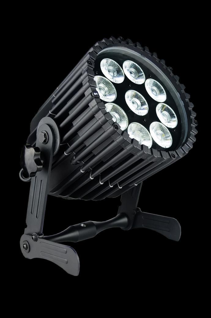
5 3.1 BRACKET The AX10 SpotMax is fitted with a foldable bracket. This is beneficial for storage, transportation, and charging as the legs fold parallel to each other. It allows easy carrying, too, with the ergonomic handle. The handle also contains a W 1/2 thread to attach the Super Bolt (which then can be attached to Manfrotto Super Clamps). The bolt can be ordered separately. 3.2 BATTERY While running on battery, the light adjusts its output to meet the required minimum runtime. It can be set by the control panel (6.14 R) or the AsteraApp between one and twenty hours. The battery is specified to last for 300 full discharge cycles. Its runtime will have decreased to 70% by then. To increase the battery life it is recommended to recharge as early as possible and not let the light run until the battery is depleted. If operated below 20 C, the battery runtime may be slightly shorter than predicted. This is also true if the lights are stored for a long time at cold temperature right before they are used. The light is constantly monitoring the LED temperature and dims down the brightness if it exceeds 65 C. That ensures a save and long-live operation but in a hot environment the brightness might be slightly lower. NOTE: Always store the lights with full battery. Depleted batteries must be recharged immediately, otherwise their performance will suffer. ATTENTION: The battery may be only replaced with an original Astera replacement battery STANDBY By using the AsteraApp, the light can be set to a special standby mode. In that mode, its ouput is switched off, the CRMX receiver is powered down and it enters a state of low power consumption. A full battery will supply the SpotMax roughly 20 days in standby mode. To light leaves the standby mode if the ENTER key is pressed or the standby mode is left by the AsteraApp. 3.3 BATTERY ICON AND STATUS LED The Battery Status LED is designed for being used before an event. All fixtures should have a green Status LED to ensure that the battery lasts for your upcoming event. If it is another color, recharging is recommended. While the light is connected to AC, the Status LED will be blue. While it is charging, the Battery Icon will start the charging sequence. Once the battery is fully charged the battery icon on the display will show all 3 bars (as below). If the battery is already fully charged and the power cord is plugged in, the display will show a battery with moving bars for approx seconds after which it will stop and the icon will show a full battery. Page 4
6 3.4 CHARGING Charge the light immediately after use. If charged in a flight case, make sure it is open. It is recommended to charge the lights at an ambient temperature between 0 C and 35 C. A normal charge cycle will take five to seven hours, but may take much longer if the light is hot. The light is designed to be charged while powered off. If it is connected to AC and powered on, it may charge at reduced current if enough power is available and the battery temperature is below 45 C. The light has an automatic battery bypass switch, so it can safely be used wired, this will not cause wear to the battery. 3.5 AC WIRING The light is equipped with Neutrik True1 Powercon input and output connectors. They are rated IP65 even while a connector is plugged in. Page 5

7 3.6 DIFFUSORS The effect of the diffusors can be seen below: NOTE: Each diffusor has its name inscribed on the edge (FLOOD or WALLWASH). In order to attach the diffusor, the diffusor must be slid into the Diffusor Slots, then pressed down firmly and clipped in under the Diffusor Clip. In order to remove the diffusor, the Diffusor Clip should be pressed in and the diffusor sheet should be lifted out via the Thumb Hole. Page 6
8 4 SPECIFICATION LED power: 135W Illuminants: 9 x 15W RGBAW Philips LEDs Luminous Flux*: 3,350lm (at White 4000K) Emittance*: 10,350lx (at 2m; White 4000K) CRI*: up to 92 Beam Angle: 13 Input Voltage: V 47-63Hz 1.8A/115VAC 1.0A/230VAC Inrush Current: COLD START 70A/230VAC Battery Runtime: up to 20hrs (seamless runtime) Wireless Module: EU: MHz US: MHz 2.4 GHz Operating Temperature: 0 C 40 C 32 F 104 F Relative Humidity: 0%-100% Size: L279mm x W253mm x H296mm 10.9 x 11.6 x 9.9 Weight: 7.98 kg 17.5lbs IP Rating: IP65 * Typical Values 5 TROUBLESHOOTING The fixture does not turn on. The battery may be empty. Connect it to the AC and try again. The fixture turns on and the display is on, but the LEDs do not emit light. The fixture could be set to BLACKOUT mode, set to display black color or is operating in DMX mode and doesn t receive a valid signal. It is good practice to do a RESET SETTINGS (Chapter 6.19) between setups. The fixture is not working correctly - it does not display the color or effect chosen. The fixture may still be operating under a previous setting. It is good practice to do a RESET SETTINGS (Chapter 6.19) between setups. After completing a RESET SETTINGS, the fixture still cannot be controlled by AsteraApp. Make sure the RADIO PIN (Chapter 6.18) of the fixture and AsteraApp is the same. The fixture does not run long enough on battery. The required RUNTIME can be set. It defaults to 5h. To achieve a greater battery runtime, set the RUNTIME to the required value. Alternatively, program the fixture to only display colors that use less power, such as Red, Green and Blue. If the runtime is still too short, consider that it is reduced slightly if the battery is very cold. The power cable is connected but the fixture is not charging. The battery may be fully charged. Refer to chapter for more details. The fixture will only commence charging when its battery has a temperature of 45 or less. Turn the fixture off and let it cool down; once cold enough, it will start charging. If it still not charging, consult our website. Page 7

9 6 OPERATION 6.1 ASTERARGB COLOR SPACE The lights work with a specially optimized RGB color space, the AsteraRGB color space. It is designed to eliminate the need to control each color individually to display a certain color. Instead, the light calculates the optimum combination of all colors based on an RGB value. It considers each LED chip s temperature as well as an optimal color rendering. Due to this, it is possible to reproduce colors with high accuracy. It is possible to calculate an AsteraRGB representation for any CIE color. The easiest way to do this is with the AsteraApp : Go to the color picker and add a new favorite color Go to favorite colors and edit it The dialog on the right will open. It allows you to find AsteraRGB values for a certain color temperature. S-RGB or CIE1931 values can be calculated to AsteraRGB by pressing the corresponding buttons. The primaries of the AsteraRGB are defined as: Red Green Blue xr yr xg yg xb yb White Point x y The light also includes the Dynamic Powerboost feature. It ensures that colors that consume less electrical power are boosted slightly, while power power-consuming colors are slightly compressed. This maximizes the brightness while maintaining the desired battery runtime. While controlling with the AsteraApp or by the Control Panel, only RGB values can be set. By DMX control, it is possible to control all colors separately. But it should be noted, that then temperature compensation is only available for Red, Green and Blue; all other colors will experience temperature drift, their brightness will not be constant. Page 8


10 6.2 WAYS TO CONTROL The light can be controlled in several ways: Use Astera s ARC1 infrared remote control, point it at individual lights and press the desired effect. Note that the IR sensor is on the AX10 s rear side. The AsteraApp is an efficient way to quickly create a customized light show. It can group several lights together, address individual lights or groups of lights, and send complex effects with a user defined color palette to all lights in range. For additional information refer to chapter 7. Alternatively, the Astera ARC2 remote control can be used. The light can also be controlled by CRMX wireless DMX, the built in receiver is compatible with all LumenRadio CRMX transmitters as well as W-DMX G2, G3, G4 and G4S transmitters (G4 and G4S in 2.4 GHz mode only). You can also use an Astera ART3 Wireless DMX Transmitter to send DMX in the UHF frequency band, although CRMX is the recommended method. Power the light on/off, set a static color or change its settings. CRMX is a trademark of LumenRadio AB W-DMX is a trademark of Wireless Solution Sweden AB 6.3 CONTROL BY INFRARED WITH ARC1 The light can be controlled by the infrared remote control if: INPUT SELECT is set to AUTO or REMOTE CONTROL (refer to chapter 6.10). The light is currently NOT operated by DMX. If it is, only ON and OFF will work while INPUT SELECT is set to AUTO. The ARC1 is very handy to switch several lights on or off at a time. Page 9
11 6.4 CONTROL BY THE ASTERAAPP Your light has a built in standalone engine. It can display static colors or replay a number of predefined effect patterns with a customizable color palette. With the AsteraApp these effects can be created and be sent to the light by the built in UHF receiver. The effects are just triggered and then each light replays it autonomously until it receives a new effect. Lights can be grouped into sets. This way they can be controlled separately and also effects can stretch over up to 32 lights. Also, you can remotely adjust your lights settings, this eases DMX setup for example. For more details refer to chapter CONTROL BY WIRELESS DMX To pair your light to a CRMX or W-DMX transmitter, make sure that: Your light is not currently paired to a transmitter. To unpair it refer to chapter INPUT SELECT is either set to AUTO and the light is still in detect mode or- INPUT SELECT is set to CRMX wireless DMX; for details refer to chapter Then press the button on your transmitter. After 10 seconds the light should be paired and show the appropriate status screen (chapter 6.7). If you prefer to use an Astera ART3 wireless transmitter, set INPUT SELECT to Astera wireless DMX and refer to the ART3 s user manual for details. NOTE: If you experience difficulties pairing your light, it is recommended to set INPUT SELECT to CRMX wireless DMX first. This will make sure that the CRMX status screen is displayed. Page 10

12 6.6 CONTROL PANEL Blue Mode Blue mode is an easy way to pair your light with the AsteraApp. To enter Blue Mode, hold down the POWER button for 3 seconds while the light is switched on. It will start to flicker blue. 6.7 STATUS SCREEN The status screen is shown after power up. The light also returns to the status screen if no keys are pressed for three minutes. It shows: In the FIRST line what input is currently active In the SECOND line the current DMX and SET address INPUT: DETECTING SET:001 DMX:001 REMOTE CONTROL SET:001 DMX:001 STANDALONE SET:001 DMX:001 CRMX: SIGNAL 99% SET:001 DMX:001 WLDMX: NO LINK SET:001 DMX:001 EMERGENCY LIGHT SET:001 DMX:001 INPUT SELECT is set to AUTO and the light did not yet latch to one input source. The light is latched to REMOTE CONTROL mode. INPUT SELECT is set to STANDALONE. The light can no longer be controlled by any wireless signal. The light is latched to CRMX mode. The light is latched to Astera wireless DMX mode. Emergency light mode can be active because either AC FAIL or DMX FAIL being set to EMERGENCY LIGHT. STANDBY SET:001 DMX:001 The standby mode saves power; the light is off and waiting for a leave standby command received by the AsteraApp. ALARM DO NOT STEAL THI ACCEPT CONFIG? SET:001 DMX:001 Theft alarm is active. If the AsteraApp is asking to tap a light and this is shown, press the ENTER key shortly to accept. Page 11
13 6.8 MAIN MENU OPTIONS The main menu can be entered from the status screen by pressing MENU or +. To cycle between the main menu entries, press the + or keys. Pressing MENU again will go back to the status screen. INPUT SELECT STATIC COLOR DMX ADDRESS DMX SETTINGS UNPAIR CRMX RUNTIME STANDALONE AC FAILURE INFO RESET SETTINGS Used to change the input source or set it to AUTO. Entering this menu resets all STANDALONE settings to default and makes the light display a static color. Set the DMX address. Set the DMX parameters. Unpair from a CRMX or W-DMX transmitter. Set the lights runtime on battery in hours. Set parameters of the standalone engine. The light can react to the loss of AC power input. Information about the light: radio pin, firmware version, battery status, ect. Reset all user settings to default. Should be done after each usage to ensure consistent behavior. The RADIO PIN is NOT reset. 6.9 MENU SHORTCUTS To get to the DMX address setting, press the ENTER key twice from the status screen. To open the DMX settings menu, press ENTER, then the + key and ENTER again. To reset the light to default settings, press the key, then ENTER and again ENTER. Page 12
14 6.10 INPUT SELECT The light accepts several input sources. By default, it is set to AUTO. In this mode, it listens to all sources, and the first source that becomes active is latched. Once a source is latched, the light will not listen to any other source anymore. This latched source is cleared by powering down the light or changing the INPUT SELECT manually. INPUT SELECT INPUT SELECT AUTO INPUT SELECT STANDALONE INPUT SELECT REMOTE CONTROL INPUT SELECT Astera wirel.dmx INPUT SELECT CRMX wirel. DMX Auto mode; the lights waits for any input signal and latches the first detected source. In standalone mode, neither wireless DMX nor remote control is accepted. The light can be control by the AsteraApp, but any DMX signal is ignored. Only Astera wireless DMX is accepted, all other sources are ignored. Only CRMX/W-DMX wireless DMX is accepted, all other sources are ignored. The following table shows what sources are accepted for each setting: Source INPUT SELECT AUTO, none latched AUTO, STANDALONE latched AUTO, REMOTE CONTROL latched AUTO, Astera wirel. DMX latched AUTO, CRMX wirel. DMX latched STANDALONE REMOTE CONTROL Astera wirel. DMX CRMX wirel. DMX AsteraApp : change colors AsteraApp : STANDBY, RUNTIME, ALARM AsteraApp : DMX Settings Astera Wireless DMX CRMX Wireless DMX Infrared Remote The Light s Control Panel HINT: To avoid the light automatically latching onto CRMX while you want to control it by remote control, please do UNPAIR CRMX (chapter 6.15). As soon as the remote control is latched, the CRMX receiver will no longer accept pairing requests. Page 13
15 6.11 SELECT A STATIC COLOR To make the light show a static color, enter this menu. Immediately when it s entered, all previous STANDALONE settings are cleared to default and the INPUT SELECT is latched to STANDALONE. This is valid until the next power-up only. To make sure the light also shows a static color after the next power up, set INPUT SELECT to STANDALONE and not AUTO. STATIC COLOR Static Color: RED A number of predefined colors are available while scrolling through the menu. See below for a full table. Static Color: 6500K Static Color: INDEX COLOR Static Color: CUSTOM COLOR By entering the INDEX COLOR menu, a number of predefined colors similar to those of common gels are available for selection. To set a color by its red, green and blue value, enter here Predefined Colors Color Red Green Blue RED ORANGE YELLOW GREEN CYAN BLUE VIOLET PINK BLACK K K K K K Page 14
16 6.12 DMX SETTINGS DMX SETTINGS DMX Settings: DMX TAB A number of DMX tables are available, see below for details. DMX Settings: STROBE For each of the tables, the strobe channel can be enabled or disabled. DMX Settings: DMX FAIL If the DMX signal is lost, the light can either HOLD the current output, switch to STANDALONE operation, to BLACK or EMERGENCY LIGHT, which means white 4000K. See chapter DMX Tables Each of the tables can optionally contain a strobe channel. It can be switched on or off by the STROBE menu. The tables below list it, but in case it is set to OFF, the DMX-channels are unused RGB S CHANNEL VALUE FUNCTION RED GREEN BLUE 4 STROBE (only if STROBE is ON) 0..3 OFF 4 RANDOM FAST 5 RANDOM MEDIUM 6 RANDOM SLOW Variable strobe RGBW S CHANNEL VALUE FUNCTION RED GREEN BLUE WHITE 5 STROBE (only if STROBE is ON) 0..3 OFF 4 RANDOM FAST 5 RANDOM MEDIUM 6 RANDOM SLOW Variable strobe RGBAW S CHANNEL VALUE FUNCTION RED GREEN BLUE AMBER WHITE 6 STROBE (only if STROBE is ON) 0..3 OFF 4 RANDOM FAST 5 RANDOM MEDIUM 6 RANDOM SLOW Variable strobe Page 15
17 RGB CCT DIM IND S CHANNEL VALUE FUNCTION RED GREEN BLUE 4 COLOR TEMPERATURE (CCT) 0..4 no effect display color temperature; CCT overwrites the RGB setting Formular: CCT = *DMX-Value Example: 50 -> 3000K 100 -> 4000K 150 -> 5000K Dimmer 6 INDEX COLOR 0..4 no effect display index color (common gels); INDEX COLOR overwrites both, RGB and CCT. 7 STROBE (only if STROBE is ON) 0..3 OFF 4 RANDOM FAST 5 RANDOM MEDIUM 6 RANDOM SLOW Variable strobe DIM RGB S CHANNEL VALUE FUNCTION Dimmer RED GREEN BLUE 5 STROBE (only if STROBE is ON) 0..3 OFF 4 RANDOM FAST 5 RANDOM MEDIUM 6 RANDOM SLOW Variable strobe DIM RGBW S CHANNEL VALUE FUNCTION Dimmer RED GREEN BLUE WHITE 6 STROBE (only if STROBE is ON) 0..3 OFF 4 RANDOM FAST 5 RANDOM MEDIUM 6 RANDOM SLOW Variable strobe DIM RGBAW S CHANNEL VALUE FUNCTION Dimmer RED GREEN BLUE AMBER WHITE 7 STROBE (only if STROBE is ON) 0..3 OFF 4 RANDOM FAST 5 RANDOM MEDIUM 6 RANDOM SLOW Variable strobe Page 16
18 Effect Modes There are two effect modes available. They offer a comprehensive control of the built in standalone engine. Settings that can otherwise only be changed on the LCD menu or by the AsteraApp can be directly adjusted by DMX. The two effect modes only differ in the way the color palette of four colors is set: either by RGB or by a single channel, like a color wheel. In that case, common gels can be selected directly. Strobe is always enabled for the effect modes. CHANNEL VALUE FUNCTION EFFECT MODE FIX EFFECT MODE RGB INTENSITY 2 2 STROBE 0..3 OFF 4 RANDOM FAST 5 RANDOM MEDIUM 6 RANDOM SLOW Variable strobe 3 3 PROGRAM: 0..7 ONE COLOR STATIC TWO COLOR STATIC THREE COLOR STATIC FOUR COLOR STATIC ONE COLOR FADE TWO COLOR FADE THREE COLOR FADE FOUR COLOR FADE SIMPLE RUNNING DOUBLE RUNNING TWO COL RUNNING FLAG RUNNING DOUBLE FLAG RUNNING SPIRAL 4 COLOR SPIRAL 2 COLOR RAINBOW FIRE ROTOR ROTOR SPLIT ROTOR SPLIT SPEED FADE 6 6 DIRECTION: FFW+LOOP FFW REW REW+LOOP 7 7 SIZE: Defines the virtual size of the program in groups. For example if SIZE is set to 2 groups, only half of the program is shown on the unit Group Groups Groups Groups 8 8 OFFSET: If SIZE is set to >1 group, the units pixels can be shifted within the virtually larger program. Increasing the OFFSET parameter scrolls the position of the unit within the virtual large program RESTART PROGRAM if value is changed, the program starts again from the beginning (useful if DIRECTION is not set to loop) 10 INDEX COLOR 1 11 INDEX COLOR 2 12 INDEX COLOR 3 13 INDEX COLOR 4 10 RED 1 11 GREEN 1 12 BLUE 1 13 RED 2 14 GREEN 2 15 BLUE 2 16 RED 3 17 GREEN 3 18 BLUE 3 19 RED 4 20 GREEN 4 21 BLUE 4 Page 17
19 6.13 DMX FAIL It can be set what the lights should do when the DMX signal is lost. DMX Settings: DMX FAIL DMX FAIL HOLD The last DMX input is still shown, even if the DMX signal is lost. DMX FAIL EMERGENCY LIGHT The light will show a 4000K white as soon as the DMX signal is lost. DMX FAIL BLACKOUT The light will go dark if DMX signal is lost. DMX FAIL STANDALONE The light will switch temporarily to standalone mode if the DMX signal is lost and show for example a preset static color RUNTIME RUNTIME RUNTIME 1h The light is able to adjust its power to meet a certain runtime on battery. The runtime is always calculated for a full battery. RUNTIME 20h EXAMPLE: If the light is required to light during an eight hour event, and one hour of setup time is scheduled, then the runtime should be set to nine hours immediately after the first power up. Please note, that the light should not be stored below 20 C before an event, otherwise the runtime might be shorter than calculated. More details on the built in battery can be found at chapter 3.2. For additional power-savings refer to the AsteraApp manual. Page 18
20 6.15 UNPAIR CRMX UNPAIR CRMX Once your light is paired to a CRMX or W-DMX transmitter, it cannot be paired to another one until it is unpaired. This can be either done by using the button on the transmitter that is currently paired or on the light directly. If you wish to unpair your CRMX wireless DMX receiver from a Lumen Radio or W-DMX transmitter, go to UNPAIR CRMX and press enter. NOTE: The CRMX receiver is only powered while INPUT SELECT is: set to CRMX wireless DMX or AUTO and either CRMX is latched or no source is latched yet. For details in INPUT SELECT refer to chapter Page 19
21 6.16 STANDALONE STANDALONE Standalone: PROGRAM Standalone: INTENSITY Standalone: SPEED Standalone: FADE Select one of the predefined patters, see table below. Sets the dimmer level. The time that one cycle of the program takes to complete. The fade behavior between each step of the program. 0% means, no fading 100% means full fading, fade-is directly followed by fade-out. Standalone: COLOR C1 Standalone: COLOR C4 The color palette of the programs consist of up to four colors. They can be set individually. See chapter 6.11 for details on how to set a color. Standalone: SET ADDRESS Standalone: SET SIZE Standalone: POS IN SET The AsteraApp can control sets of lights individually. The set address can be 1 to 254. This setting is normally done by the set-wizard in the AsteraApp. Several lights can form a virtual big light. Programs like running light will then run over all those lights one by one. This parameter tells how many lights should form that virtual light; up to 32. Tells the lights position in the big virtual light, Standalone: GROUP ADDRESS Group addressing is supported by the ARC2, please refer to the ARC2 manual. Page 20
22 Predefined Programs The predefined programs may use more than one pixel. To display these effects properly with your light, it is first necessary to group them into Flow-Sets and control them by the AsteraApp (see chapter 7.4). If several lights are grouped into a Flow-Set, they form a virtual big light with several pixels. Name ONE COLOR STATIC TWO COLOR STATIC THREE COLOR STATIC FOUR COLOR STATIC ONE COLOR FADE TWO COLOR FADE THREE COLOR FADE FOUR COLOR FADE SIMPLE RUNNING DOUBLE RUNNING TWO COL RUNNING FLAG RUNNING DOUBLE FLAG RUNNING SPIRAL 4 COLORS SPIRAL 2 COLORS RAINBOW FIRE Pattern A static color is displayed on the whole virtual light. The virtual light is split into two halfs and two colors are displayed. The virtual light is split into three parts and three colors are displayed. The virtual light is split into four parts and four colors are displayed. For all FADE programs, the whole color palette of four colors is used. Those colors are faded in and out one by one. Here, the whole virtual light shows the same color. The virtual light is split and shows two colors at a time. The virtual light is split and shows three colors at a time. The virtual light is split and shows four colors at a time. A running light; the background and the running pixels color can be set. Two pixels are running in opposite direction. The two pixels are of different color even. A three color flag is running over the background color. Two flags are running over background in opposite direction. The color is changed pixel by pixel. All four colors are used one after the other. The color changes between color 1 and 2 from the outside to the inside, pixel by pixel. A rainbow effect is displayed. The fire effect is a random flicker between two colors, background and flickering color. NOTE: It is highly recommended to check out the effects editor of the AsteraApp to get a better understanding of how those programs work. Also, many programs look similar if the lamp is NOT grouped into a Flow-Set AC FAILURE (EMERGENCY LIGHT) The light can react to the loss of AC power in several ways. As soon as AC is present again, the light resumes normal operation. AC FAILURE AC FAILURE NO ACTION No special behavior on AC loss. AC FAILURE BLACKOUT The light will turn dark if AC is lost. AC FAILURE EMERGENCY LIGHT The light will switch to a 4000K white as soon as the AC is lost. Page 21
23 6.18 INFO INFO Radio PIN: 0000 Read/set the RADIO PIN. To change the pin, press ENTER. Adjust each digit with the + and keys, cycle through the digits with the MENU key. When finished, press ENTER again. Serial number: xx Tells the serial number of the light and the CPU type (43xx). Firmware version U HW001 The firmware version and hardware version of the light. Power-on hours: 00001h The hour-counter is counting up as long as the light is powered up. It does not count if the light is powered off and charging. RF link: -36.0dBm -0.0ppm While the light is receiving an UHF signal, this tells the signal strength and deviation. Battery state: 100% The current charging state of the battery in percent. Calibration: Gives information about the LED calibration stored in the light, for service reference only RESET SETTINGS RESET SETTINGS HINT ARE YOU SURE? NO YES Return the light to the default settings. This may be done before each use to start from a known point. The RADIO PIN and the CRMX pairing stay. It is highly recommended to reset the light s settings after each event to ensure a clear start for the next usage. Page 22

24 7 USING THE LIGHT WITH THE ASTERAAPP The buttons of the AX10 only allow a basic operation of the light. To gain full control over all features, the AsteraApp should be used. The AsteraApp is an efficient way to quickly create a customized light show. It can group several lights together, address individual lights or groups of lights, and send complex effects with a user defined color palette to all lights in range. Additionally, it can be used to adjust the lights settings remotely. The AsteraBox is needed to interface your Android device with the lights. It communicates to the Android device by Bluetooth and controls the lights by UHF. 7.1 PAIR YOUR LIGHT WITH THE ASTERAAPP The connection is secured by a 4 digit Radio Pin. Only if the lights pin matches the AsteraApp pin, lights are controllable. The pairing process transmits the radio pin from the app to the light and stores it there. 1. Choose a unique Radio Pin in the app. 2. Switch the light into blue mode, see chapter Press the Pair with Lights button in the AsteraApp. NOTE: Alternatively, you can set the Radio Pin manually at the Control Panel of the light. Refer to chapter 6.18 for details. Page 23


.")
25 7.2 POWERFUL LIGHT CONTROL Your light has a built in standalone engine. It can display static colors or replay a number of predefined effect patterns with a customizable color palette. With the AsteraApp these effects can be created and be sent to the light by the built in UHF receiver. The effects are just triggered and then each light replays them autonomously until a new effect is sent. Lights can be grouped into sets. This way they can be controlled separately and also effects can stretch over up to 32 lights. 7.3 CHANGE THE COLOR On the AsteraApp main screen, press Just Red. Once in the editor, press C1. Now the lights color can be changed. The 123 button offers common color gels. Hit the sort button to sort by color or number (1). To add a color to the favorites, press (2). To edit an existing favorite color, select it and press the pen (1). The editor will open. RGB values can be adjusted directly. Also a color temperature can be converted to RGB. Page 24

 and then the + sign (2) to")
.")
26 7.4 CREATE A SET Before the more powerful effects can be reviewed, it is recommended to create a Flow-Set first. Each light can be assigned to one set. Two types of sets are available: SYNC SET All lights that are assigned to a Sync-Set can be controlled together. They will do exactly the same. CREATE A SYNC-SET: On the AsteraApp main screen, first press the Targets button (1) and then the + sign (2) to add a new target. Choose Sync-Set. Now all lights will flicker every two seconds. Tap your light to add it to the set (chapter 6.7Error! Reference source not found.). Additionally, the name of the set can be customized. When finished, press the save button. Page 25


27 7.4.2 FLOW SET By using a Flow-Set, lights can also be controlled together. But additionally, they are assigned to positions inside the Flow-Set and so form a virtual light with several pixels. All effects, like a running light, are stretched over this virtual light. CREAT A FLOW-SET: On the AsteraApp main screen, first press the Targets button (1) and then the + sign (2) to add a new target. Then choose Flow-Set. Each flow set can have up to 32 positions. Once the correct number is entered, press Confirm. Now your lights will flicker every two seconds. To add a light to the currently shown positon of this set, press its button. Walk through the positions by Previous and Next and assign your lights. When finished, press the save button on top. 7.5 TARGETING LIGHTS Once you have created a set, you may now choose to control it. By default All lights are targeted. That includes all sets. It is possible to target more than one set at a time. NOTE: Even while targeting All Lights the Flow-Sets position arrangements persist. The lights still form a virtual big light of several positions. To modify, delete or arrange targets, use the pen button (1). Page 26


28 7.6 CHANGING THE EFFECT On the AsteraApp main screen, press Wedding (1), then enter the editor (2). Set Crossfade to 0% and Speed to around 2 seconds. You should see a clean running light now. The White light will run over a pink background. The effect can be changed by sliding the effect picker and choosing a sub-effect below it. Again the colors can be adjusted, too. After the effect is adjusted, it may be saved back to the main screen by pressing the save button. AN EFFECT CAN BE HIGHLY CUSTOMIZED: The speed tells how long it will take for the effect to complete one cycle. The crossfade tells if the light will fade from step to step. If it is set to 0% an immediate change is visible. If set to 100% the changes will be soft. Stroboscope effect can be enabled and seamlessly adjusted in speed. Additionally, three random stroboscope options are available: slow, medium and fast. Each effect can be adjusted in brightness as well. Page 27


29 7.7 LIST OF EFFECTS The effects patterns are pre-defined and cannot be modified by the user. They are preprogrammed inside of each light. Still they can be parameterized. These effects are: A static color is displayed. There are also options that show two, three or four static colors at a time. The Flow-Set is then divided into several parts of equal length: Fading colors. The four defined colors are displayed one after the other. The setup fade is applied between them. Again, the Flow-Set can be split in up to four segments. From both sides of a Flow-Set, the color changes position by position from C1 to C2. Once the whole Set is C2, it changes back to C1 in the same way. The color of the Flow-Set changes position by position. After all positions show the same color, a new cycle is started. Several variations of running lights are available. The Fire effect shows a random flickering effect. The background color and the color of the flickering effect can be adjusted. The rainbow effect shows a color change through all colors. Only its speed can be adjusted. Chaser effects provide an efficient means to create dancefloor lighting. The static chaser exchanges the color of the lights according to the tapped-in beat. The colors are randomly chosen. The effect can be adjusted to show up to 4 different colors at a time. The Moving Chasers overlay the static chaser by a second movement of the four displayed colors over the available positions of a Flow-Set. This gets mostly interesting of the Moving Strobe is chosen. Then, only some of the positions strobe and they are moving. So the strobe effect moves over the Flow-Set. When using the Chaser With Background, additionally a color can be selected that is mostly used, the background color. Page 28
30 7.8 CHASER EFFECTS IN DEEP To display chaser effects it is recommended to setup a Flow-Set with a multiple of four positions. This is the way they will be shown best. Those four positions could then be arranged in the corners of a dance floor for example. Use the tap-sync button to tap the beat of the music; the Chaser Effects will base their color changing on that beat then. The Chaser Effects offer additional controls The Emphasis adjusts the way the colors are exchanged by the chaser: Emphasis -2-1 Effect The four colors of the palette are exchanged one by one. Every beat changes only one color. Same as -2, but the color change is animated with the color-wheel effect; it mimics the color change of a traditional color wheel, showing intermediate colors during the change. 0 All four colors are exchanged on every beat. 1 Same as 0, but the color wheel effect is added. 2 3 Same as 0, but on the fourth beat, all colors go black. They come on again on the next beat. Same as 0, but all colors go black on every second beat. This setting produces a strong on-off effect in sync with the beat. The softness influences the fading between colors that happens on every beat. 0% will generate a hard change of the colors, while 100% makes them fade very slowly. A random button is added to the color bar. If it is latched, random colors are chosen on every beat. If not (like in the above picture), then the colors are always chosen randomly from the color pallet of four. This is useful to intentionally narrow down the color choice. Nice effect can be generated by setting some of them to black. Page 29

.")


31 7.9 THE MAIN SCREEN Here each program is represented by a tile. Those tiles can be edited and freely positioned. Several pages of tiles are available. To move or delete a tile, press the pen icon (2). A popup will show the available actions. To add a new program tile, press the + icon (1). While adding a tile, either a default Static Red or the currently running program can be selected. Additionally, special function tiles are available Function Tiles Tapping this tile several times to the beat will let the Chaser Effects change their colors to the beat. A chaser effect has a dancer symbol on the tile. This button can be used to quickly blackout lights. The currently set target must be observed, as the blackout function will only affect the currently targeted lights. Page 30

32 7.10 BRIGHTNESS Additionally to each programs brightness slider mentioned in chapter 7.6, a master brightness control is available. As soon as more than one Set is created and at least one set is currently targeted, a sub-master for each Set is shown. Otherwise, only one slider is available. It controls the brightness of all currently targeted lights Set Sub-Masters Each Set has its own brightness slider. Additionally, there is a master slider that controls the brightness of all Sets simultaneously. This is very similar to the group brightness control of common lighting desks. NOTE: The Set-Masters are only shown if: a) More than one Set has been created before b) Only Set-Targets are currently selected. Selecting any other type of target, like All Lights will hide the Set-Masters. This is necessary to avoid that one lights gets redundant brightness information; it would flicker constantly between different brightness levels. Page 31


33 7.11 RUNTIME The light is able to adjust its power to meet a certain runtime on battery. The runtime is always calculated for a full battery. Example: If the light is required to light during an eight hour event, and one hour of setup time is scheduled, then the runtime should be set to nine hours immediately after the first power up. Please note, that the light should not be stored below 20 C before an event, otherwise the runtime might be shorter than calculated. More details on the built in battery can be found at chapter ANTI-FLICKER The PWM refresh rate of this light is Hz by default. This frequency can be freely adjusted between 200 Hz and 1205 Hz to fit different camera s frame rates. Make sure you have targeted the lights you wish to adjust (chapter 7.5). Then press the Anti-Flicker. NOTE: Slide the fps to adjust to default values for a framerate. Slide the Hz to fine-adjust. Press the highlighted frequency to enter a custom value between 200 and 1205 Hz. The Anti-Flicker adjustment is preserved in case the lamp is powered off. It is set back to the default 599.4Hz once a Reset Settings (chapter 6.19) is done. The adjusted frequency is used no matter what input source is currently active. Also during DMX operation. Page 32


34 7.13 THEFT ALARM Your light is equipped with a theft alarm. A motion sensor in the light detects when it is moved/taken away and a small siren will sound to deter potential thieves. First make sure your Radio Pin is different from See chapter 7.1 how to change it. Then press the ON button. Press Activate. All targeted lights will flash shortly to indicate that they are now armed. If the siren is set to DELAYED, it sounds only if the alarm persists for more than 6 seconds. The ON setting makes it sound immediately, while the OFF setting mutes it always. The sensitivity can be adjusted to meet your environment. A lower value makes a false alarm more unlikely. In case a potential thief is taking the light away while ignoring the alarm, he will most likely cause alarm events for more than 2 minutes in a row. In that case, the alarm can be set to become permanent. Then it won t stop, even if the light is placed down again. It will run until the battery is empty, rendering the light useless for the thief. In some applications it is not desirable to have the lights flashing while the alarm is enabled or disabled. It can be disabled by this option easily. The alarm can be silenced without turning it off by pressing this button. NOTE: To turn the alarm off again, an AsteraApp with the same Radio Pin must be used. Do not forget your Radio Pin! Otherwise, your light cannot be used normally anymore. Page 33
.")


35 7.14 ENTER AND LEAVE STANDBY The standby is intended to be used between setup and event (see chapter 3.2.1Error! Reference source not found.). After setup is completed, all lights may be switched to standby mode and woken up later when the event starts. This ensures that no battery runtime is wasted. This can be either done manually or automated. Press the small arrow to open the standby menu. By pressing the Now buttons, standby can be switched on or off for all currently targeted lights. Any of the Later buttons will require a time to be set. The standby will be scheduled to the specified time. NOTE: While you are using the Now function, only those lights that are currently targeted are addressed (see chapter 7.5 how to target lights). The Later function always sends to the All Lights target! Page 34
.")

36 7.15 DMX SETTINGS In order to efficiently use the light with DMX, some setting can be adjusted by the AsteraApp. Press the DMX Configuration button. Adjust all settings to your requirements, then press Send. Your lights will start to flicker. Tap the lights you wish to setup (chapter 6.7). Then press Done. Please refer to chapter 6.10, INPUT SELECT, and chapter 6.12, DMX Settings, for details on the available settings DMX Channel Assignment The current channel assignment can be always reviewed in the lower part of the screen. It is automatically calculated based on the setting of Table and Strobe. Page 35
37 8 MENU OVERVIEW Page 36
AX3 LIGHTDROP. User Manual
 AX3 LIGHTDROP User Manual 1 CONTENTS 2 Package Contents... 3 3 Safety and Handling... 3 3.1 Bracket... 4 3.2 Mounting options... 4 3.3 Battery... 5 3.4 Charging... 5 3.5 AC Wiring... 5 3.6 Diffusors...
AX5 TriplePAR. User Manual
 AX5 TriplePAR User Manual 1 CONTENTS 2 Package Contents... 3 3 Safety and Handling... 3 3.1 Bracket... 4 3.2 Hanging The AX5... 6 3.3 Kickstand... 7 3.4 Filter... 8 3.5 Battery... 9 3.6 Battery Icon and
AX7 SPOTLITE. User Manual
 AX7 SPOTLITE User Manual 1 CONTENTS 2 Package Contents... 4 3 CE and FCC Conformity... 4 4 Safety and Handling... 5 4.1 Bracket... 6 4.2 Battery... 6 4.3 Battery Icon and Status LED... 7 4.4 Charging...
Wireless Wall Washer
 USER MANUAL Wireless Wall Washer Manual Version: 3.8.33 Release Date: 29 th Nov 2013 Astera Led Technology GmbH Address : Nahestrasse 68-70, 55593 Rüdesheim an der Nahe, Germany Tel.: +49(0) 671-92028292
AX3 LIGHTDROP. User Manual
 AX3 LIGHTDROP User Manual 1 CONTENTS 2 Package Contents... 4 3 Declaration of Conformity... 4 4 Safety and Handling... 5 4.1 Bracket... 5 4.2 Mounting options... 6 4.3 Battery... 7 4.4 Charging... 7 4.5
Spectra Flood Q40. Exterior Fixture User Manual. Order code: LEDJ Version LEDJ284N - 15 Version
 Spectra Flood Q40 Exterior Fixture User Manual Order code: LEDJ284-40 Version LEDJ284N - 15 Version Safety advice WARNING FOR YOUR OWN SAFETY, PLEASE READ THIS USER MANUAL CAREFULLY BEFORE YOUR INITIAL
Casambi App User Guide
 Casambi App User Guide Version 1.5.4 2.1.2017 Casambi Technologies Oy Table of contents 1 of 28 Table of contents 1 Smart & Connected 2 Using the Casambi App 3 First time use 3 Taking luminaires into use:
SHOWLINE SL BAR 640 LINEAR WASH LUMINAIRE SPECIFICATIONS.
 GENERAL. A.) Overview. SHOWLINE SL BAR 640 LINEAR WASH LUMINAIRE SPECIFICATIONS. 1.) The luminaire shall be a color mixing luminaire employing twenty-four (24) red, green, blue, and white LED engines.
Stratos Duo RGB. User Manual. Order code: EQLED371
 Stratos Duo RGB User Manual Order code: EQLED1 Safety advice WARNING FOR YOUR OWN SAFETY, PLEASE READ THIS USER MANUAL CAREFULLY BEFORE YOUR INITIAL START-UP! Before your initial start-up, please make
SHOWLINE SL PAR 155 LED LUMINAIRE SPECIFICATIONS.
 SHOWLINE SL PAR 155 LED LUMINAIRE SPECIFICATIONS. GENERAL. A.) Overview. 1.) The luminaire shall be a color mixing luminaire employing nine (9) homogenized red, green, blue, and white LED engines. The
SHOWLINE SL epar 180 LUMINAIRE SPECIFICATIONS.
 SHOWLINE SL epar 180 LUMINAIRE SPECIFICATIONS. GENERAL. A.) Overview. 1.) The luminaire shall be a color mixing luminaire employing nineteen (19) homogenized red, green, blue, and white LED engines. The
Altman Lighting AP-150 RGBW Par Specification
 1.01 COLOR MIXING LED WASH FIXTURE A. General 1. The fixture shall be Red, Green, Blue, and White LED luminaire with motorized zoom and DMX control. The fixture shall be the AP-150 RGBW by Altman Stage
SHOWLINE SL NITRO 510C LED STROBE LUMINAIRE SPECIFICATIONS.
 GENERAL. A.) Overview. SHOWLINE SL NITRO 510C LED STROBE LUMINAIRE SPECIFICATIONS. The luminaire shall be an LED strobe luminaire employing five hundred and twenty eight (528) red, green, blue and white
Show Designer 3. Software Revision 1.15
 Show Designer 3 Software Revision 1.15 OVERVIEW... 1 REAR PANEL CONNECTIONS... 1 TOP PANEL... 2 MENU AND SETUP FUNCTIONS... 3 CHOOSE FIXTURES... 3 PATCH FIXTURES... 3 PATCH CONVENTIONAL DIMMERS... 4 COPY
SHOWLINE SL PUNCHLITE 220 LED LUMINAIRE SPECIFICATIONS.
 SHOWLINE SL PUNCHLITE 220 LED LUMINAIRE SPECIFICATIONS. GENERAL. A.) Overview. 1.) The luminaire shall be a color mixing luminaire employing nine (19) homogenized red, green, blue, and white LED engines.
SHOWLINE SL BEAM 100 LED LUMINAIRE SPECIFICATIONS.
 SHOWLINE SL BEAM 100 LED LUMINAIRE SPECIFICATIONS. GENERAL. A.) Overview. 1.) The luminaire shall be a motorized colour mixing luminaire employing seven (7) homogenized red, green, blue, and white LED
RevEAL CW with TrueSource Technology Operating Manual
 RevEAL CW with TrueSource Technology Operating Manual www.prismprojection.com Copyright 2010. Prism Projection Inc. All Rights Reserved Product Specifications and Information Subject to Change The Product(s)
SHOWLINE SL NITRO 510 LED STROBE LUMINAIRE SPECIFICATIONS.
 GENERAL. A.) Overview. SHOWLINE SL NITRO 510 LED STROBE LUMINAIRE SPECIFICATIONS. 1.) The luminaire shall be an LED strobe luminaire employing one-thousand, three-hundred and fifty (1350) white LED engines.
ORDER CODE: EQLED65 USER MANUAL
 www.prolight.co.uk ORDER CODE: EQLED65 USER MANUAL Safety WARNING FOR YOUR OWN SAFETY, PLEASE READ THIS USER MANUAL CAREFULLY BEFORE YOUR INITIAL START-UP! CAUTION! Keep this equipment away from rain,
Mini LED Pin Spot Light Model: PLS00571
 Mini LED Pin Spot Light Model: PLS00571 1 Please read these instructions carefully before use and retain for future reference. IMPORTANT SAFETY INFORMATION When using electrical appliances basic safety
Outdoor Stage PAR 12 4W Quad IR RGBW, 12 3W Quad IR UV LED PAR. user manual
 Outdoor Stage PAR 12 4W Quad IR RGBW, 12 3W Quad IR UV LED PAR user manual Musikhaus Thomann Thomann GmbH Hans-Thomann-Straße 1 96138 Burgebrach Germany Telephone: +49 (0) 9546 9223-0 E-mail: info@thomann.de
SquareLED - Aura Bar & Matrix Beam Light 100
 SquareLED - Aura Bar & Matrix Beam Light 100 1. SAFETY INSTRUCTIONS Please read these instructions carefully they include the important information about the installation usage and maintenance of this
BEAM MOVING HEAD YODN Lamp. 132W 2R MOVING HEAD Brightness / Stability USER MANUAL. Version 1.0 beta
 BEAM MOVING HEAD YODN Lamp W R MOVING HEAD Brightness / Stability This product manual contains important information about the safe installation and use of this projector. Please read and follow these
JS007WQK HEAVY DUTY WIRELESS REVERSING KIT 7 LCD DIGITAL QUAD RECORDING MONITOR with WATERPROOF CCD CAMERA
 JS007WQK HEAVY DUTY WIRELESS REVERSING KIT 7 LCD DIGITAL QUAD RECORDING MONITOR with WATERPROOF CCD CAMERA The JS007WQK is loaded with userfriendly features and is ideal for use in heavy duty vehicles.
minipointe is a tiny agile air cutter specifically designed to produce sharp beam and aerial effects especially in venues constrained by size.
 minipointe is a tiny agile air cutter specifically designed to produce sharp beam and aerial effects especially in venues constrained by size. Striking bright 0 parallel beams with glowing colours and
S30-C LED Soft Light LIGHTING - PRODUCT SPECIFICATION V1.0
 S30-C LED Soft Light LIGHTING - PRODUCT SPECIFICATION V1.0 A. General 1. The luminaire shall be a RGBW LED soft light luminaire with an electronically controlled LED light source especially with the ability
L5-C LED Fresnel L I G H T I N G - P R O D U C T S P E C I F I C A T I O N V2.2
 L5-C LED Fresnel L I G H T I N G - P R O D U C T S P E C I F I C A T I O N V2.2 A. General 1. The luminaire shall be a RGBW color mixing LED Fresnel luminaire with an electronically controlled LED light
Multi-Zone Programmable RGB ColorPlus LED Touch Controller (Remote Control) and RGB ColorPlus LED Touch Controller (Receiver)
 and RGB ColorPlus LED Touch Controller (Receiver)") 11235 West Bernardo Court, Suite 102 San Diego, CA 92127 888-880-1880 Fax: 707-281-0567 EnvironmentalLights.com Multi-Zone Programmable RGB ColorPlus LED Touch Controller (Remote Control) and RGB ColorPlus
11235 West Bernardo Court, Suite 102 San Diego, CA 92127 888-880-1880 Fax: 707-281-0567 EnvironmentalLights.com Multi-Zone Programmable RGB ColorPlus LED Touch Controller (Remote Control) and RGB ColorPlus
USER GUIDE 8-CHANNEL DMX CONTROLLER December 2013 Version 1.0 CHASE / STROBE SPEED FADE SPEED RED GREEN BLUE WHITE AMBER DIMMER INSERT
 8-CHANNEL DMX CONTROLLER RED GREEN BLUE YELLOW 1 2 3 4 5 6 CYAN ORANGE PURPLE WHITE RED GREEN BLUE WHITE AMBER DIMMER RECORD INSERT DELETE TAP CLEAR MANUAL MUSIC 1 2 3 5 6 7 AUTO CHASE / STROBE SPEED 4
ALO 030 MKII. 30 Watt DMX LED scanner. User manual
 ALO 030 MKII 30 Watt DMX LED scanner User manual Safety instructions WARNING! Always keep this device away from moisture and rain! Hazardous electrical shocks may occur! WARNING! Only connect this device
USER MANUAL. 27 Full HD Widescreen LED Monitor L27ADS
 USER MANUAL 27 Full HD Widescreen LED Monitor L27ADS TABLE OF CONTENTS 1 Getting Started 2 Control Panel/ Back Panel 3 On Screen Display 4 Technical Specs 5 Care & Maintenance 6 Troubleshooting 7 Safety
Hex-color RGBAW+UV LED strip light
 Hex-color RGBAW+UV LED strip light 2 19 SAFETY / GENERAL INSTRUCTIONS INTRODUCTION Features Specifications OVERVIEW : CONNECTIONS Rear view DIMENSIONS INSTALLATION Mounting FUNCTIONS AND SETTINGS Function
ArtFox Lighting. LED Beam Wash 19E. User manual. 6. Fixture Cleaning. Please read the instructions carefully before use
 6. Fixture Cleaning ArtFox Lighting LED Beam Wash 19E The cleaning of internal and external optical lenses and/or mirrors must be carried out periodically to optimize light output. Cleaning frequency depends
4-PROJECTOR BAR WITH 3 X 9W LEDS AND 1 X 1W FLASH LED USER GUIDE
 4-PROJECTOR BAR WITH 3 X 9W LEDS AND 1 X 1W FLASH LED USER GUIDE 10482 - Version 1 / 04-2016 English LIVESET - LIVESET - 4-Projector bar with 3 x 9W LEDs and 1 x 1W Flash LED 1 - Safety information Important
pixelpatt Light source 7x 30W RGBW multichips Effects Individual control of each RGBW pixel, Tungsten lamp emulation
 pixelpatt Continuing the retro style lighting design, the pixelpatt is a new addition to the PATT family. In spite of its eye catching retro design, pixelpatt is based on modern LED pixel controlled technology.
S30-RP LED Soft Light
 S30-RP LED Soft Light LIGHTING - PRODUCT SPECIFICATION V1.0 A. General 1. The luminaire shall be a Remote Phosphor LED soft light luminaire with an electronically controlled LED light source especially
Dragonfly Quad. User Manual V1.4. Order code: EQLED101
 Dragonfly Quad User Manual V1.4 Order code: EQLED101 Safety advice WARNING FOR YOUR OWN SAFETY, PLEASE READ THIS USER MANUAL CAREFULLY BEFORE YOUR INITIAL START-UP! Before your initial start-up, please
CHROMAPOWERLINE 100 DATASHEET
 A superpower linear TriColour LED fixture, ideal for illuminating backdrops, walls, and façades. In addition to full manual control of RGB levels, a builtin controller enables the producing of stunning
Converts any TV to Digital. MFR-300 User Guide
 Converts any TV to Digital MFR-300 User Guide Introduction Thank you for choosing this TVonics Freeview box. Record the serial number in the space provided below (the serial number can be found on the
USER MANUAL. 27 Full HD Widescreen LED Monitor L270E
 USER MANUAL 27 Full HD Widescreen LED Monitor L270E TABLE OF CONTENTS 1 Getting Started 2 Control Panel/ Back Panel 3 On Screen Display 4 Technical Specs 5 Care & Maintenance 6 Troubleshooting 7 Safety
AEROTRAK PORTABLE AIRBORNE PARTICLE COUNTER MODEL 9110 QUICK START GUIDE
 AEROTRAK PORTABLE AIRBORNE PARTICLE COUNTER MODEL 9110 QUICK START GUIDE Thank you for purchasing a TSI AeroTrak Model 9110 Portable Airborne Particle Counter (particle counter). This guide will help you
Chroma-Q Studio One 100 D
 Chroma-Q Studio One 100 D User Manual Version 1.0 September 2015, Software Version 1.6 PN: 638-0704 Warranty Statement Chroma-Q warrants to the original purchaser, with proof of purchase, that its delivered
USER MANUAL. 27" 2K QHD LED Monitor L27HAS2K
 USER MANUAL 27" 2K QHD LED Monitor L27HAS2K TABLE OF CONTENTS 1 Getting Started 2 Control Panel/ Back Panel 3 On Screen Display 4 Technical Specs 5 Troubleshooting 6 Safety Info & FCC warning 1 GETTING
Mover Beam 7 CKU (US) / CKE (EU) USER MANUAL
 / CKE (EU) USER MANUAL") Mover Beam 7 CKU01-5030 (US) / CKE01-5030 (EU) USER MANUAL Introduction Thank you for purchasing the ColorKey Mover Beam 7. Please read these instructions carefully before use. Operating this fixture according
Mover Beam 7 CKU01-5030 (US) / CKE01-5030 (EU) USER MANUAL Introduction Thank you for purchasing the ColorKey Mover Beam 7. Please read these instructions carefully before use. Operating this fixture according
ORLAND SCAN PR PR LIGHTING LTD. Yingbin Road, Dashi Panyu, Guangzhou, China
 ORLAND SCAN PR-1201 This product manual contains important information about the safe installation and use of this projector. Please read and follow these instructions carefully and keep this manual in
American DJ. Show Designer. Software Revision 2.08
 American DJ Show Designer Software Revision 2.08 American DJ 4295 Charter Street Los Angeles, CA 90058 USA E-mail: support@ameriandj.com Web: www.americandj.com OVERVIEW Show Designer is a new lighting
LA1500R USER S GUIDE.
 LA1500R USER S GUIDE www.planar.com The information contained in this document is subject to change without notice. This document contains proprietary information that is protected by copyright. All rights
1440/2880 HP RGB+WW+CW
 office Nano*Pix 1440/2880 HP RGB+WW+CW User Manual Rev 7/2014 V4.4 Specifications subject to change without notice. Seite 1 Product Description Thank you for choosing this LDDE Nano*Pix 1440 HP / 2880
Spiider THE NEXT BIG THING FROM ROBE!
 Spiider THE NEXT BIG THING FROM ROBE! Spiider, a superbright next generation of LED WashBeam luminaires, using 18x 30 Watt and 1x 60 Watt LEDs and combining it with a very efficient 12,5:1 zoom optical
6X3W RGB LEDS PROJECTOR FOR PROFESSIONAL TRUSSES USER GUIDE / Version 1
 6X3W RGB LEDS PROJECTOR FOR PROFESSIONAL TRUSSES USER GUIDE 10364-07-2015 / Version 1 English MINITRUSS-6TCb - 6x3W RGB LEDs projector for professional trusses 2 MINITRUSS-6TCb - 6x3W RGB LEDs projector
WASH MOVING HEAD M7W15RGBW USER MANUAL. For safety, please read this user manual carefully before initial use.
 1 WASH MOVING HEAD M7W15RGBW USER MANUAL For safety, please read this user manual carefully before initial use. Event Lighting reserves the right to revise the manual at any time. Information and specifications
ivw-ud322 / ivw-ud322f
 ivw-ud322 / ivw-ud322f Video Wall Controller Supports 2 x 2, 2 x 1, 3 x 1, 1 x 3, 4 x 1 & 1 x 4 Video Wall Array User Manual Rev. 1.01 i Notice Thank you for choosing inds products! This user manual provides
PRODUCT MANUAL. DMX BOSS Wi-Fi Controller. Product Description
 Product Description The DMX Boss is a new cutting edge DMX Controller that includes many new exciting features not seen before. The DMX Boss includes a standard Glass touch control interface as well as
Outdoor Stage PAR 12 4 W Quad, 12 3 W UV IR LED PAR. user manual
 Outdoor Stage PAR 12 4 W Quad, 12 3 W UV IR LED PAR user manual Musikhaus Thomann Thomann GmbH Hans-Thomann-Straße 1 96138 Burgebrach Germany Telephone: +49 (0) 9546 9223-0 E-mail: info@thomann.de Internet:
Litile34 OPERATION MANUAL
 Litile34 OPERATION MANUAL Seamless Tiled Panel Wall Solution for Large Area Digital Signage Display (1st Edition 3/25/2009) All information is subject to change without notice. Approved by Checked by Prepared
SV-LCD50. Installation and User Guide. Thin-Film Transistor (TFT) Liquid Crystal Display (LCD) Color Rear Vision Monitor. Version 1.
 Liquid Crystal Display (LCD) Color Rear Vision Monitor. Version 1.") SV-LCD50 Installation and User Guide Thin-Film Transistor (TFT) Liquid Crystal Display (LCD) Color Rear Vision Monitor Version 1.00 August 2004 SV-LCD50 Installation and User Guide TFT LCD Color Rear Vision
SV-LCD50 Installation and User Guide Thin-Film Transistor (TFT) Liquid Crystal Display (LCD) Color Rear Vision Monitor Version 1.00 August 2004 SV-LCD50 Installation and User Guide TFT LCD Color Rear Vision
DMX Channel Index. Revision F Covers firmware version
 DMX Channel Index Revision F Covers firmware version 118-14-13 Normal mode (16 DMX channels) Channel Function Description 1 2 Pan coarse Pan fine Left right in 1.2 increments (16 bit) 3 Tilt coarse Up
P XGA TFT Monitor. User s Manual
 P6151 15 XGA TFT Monitor User s Manual Disclaimers This manual has been carefully checked and believed to contain accurate information. Axiomtek Co., Ltd. assumes no responsibility for any infringements
USER MANUAL Full HD Widescreen LED Monitor L215ADS
 USER MANUAL 21.5 Full HD Widescreen LED Monitor L215ADS TABLE OF CONTENTS 1 Getting Started 2 Control Panel/ Back Panel 3 On Screen Display 4 Technical Specs 5 Care & Maintenance 6 Troubleshooting 7 Safety
R Rxx-Vxxxx-L334-x
 CEZOS 81-534 Gdynia POLAND, Olgierda 88/b tel. +48 58 664 88 61 cezos@cezos.com www.cezos.com Date: 29.08.2016 Revision 1.2 INTRODUCTION RGBW LED module is an advanced light source designed for the best
Be sure to run the vehicle engine while using this unit to avoid battery exhaustion.
 CAUTION: TO REDUCE THE RISK OF ELECTRIC SHOCK DO NOT REMOVE COVER (OR BACK) NO USER-SERVICEABLE PARTS INSIDE REFER SERVICING TO QUALIFIED SERVICE PERSONNE; Please Read all of these instructions regarding
Noise Detector ND-1 Operating Manual
 Noise Detector ND-1 Operating Manual SPECTRADYNAMICS, INC 1849 Cherry St. Unit 2 Louisville, CO 80027 Phone: (303) 665-1852 Fax: (303) 604-6088 Table of Contents ND-1 Description...... 3 Safety and Preparation
USER MANUAL Full HD Widescreen LED Monitor L236VA
 USER MANUAL 23.6 Full HD Widescreen LED Monitor L236VA TABLE OF CONTENTS 1 Getting Started 2 Control Panel/ Back Panel 3 On Screen Display 4 Technical Specs 5 Care & Maintenance 6 Troubleshooting 7 Safety
USER MANUAL Full HD Widescreen LED Monitor L215IPS
 USER MANUAL 21.5 Full HD Widescreen LED Monitor L215IPS TABLE OF CONTENTS 1 Getting Started 2 Control Panel/ Back Panel 3 On Screen Display 4 Technical Specs 5 Care & Maintenance 6 Troubleshooting 7 Safety
DCL9AW. User Manual. English
 DCL9AW User Manual English PRECAUTIONS Information for users applicable in European Union countries 1 Information for users applicable in United States of America 1 Installation 1 Power connection 1 Maintenance
ZOOM LED Spot. Market leading colour control and future proofed functionality with simplicity of use Designed and built in the UK
 ZOOM LED Spot Market leading colour control and future proofed functionality with simplicity of use Designed and built in the UK Design Philosophy We talked with leading Lighting Designers, Installation/Rental
STRAND LIGHTING 200F 7-INCH TUNGSTEN LED TELEVISION FRESNEL SPECIFICATION.
 STRAND LIGHTING 200F 7-INCH TUNGSTEN LED TELEVISION FRESNEL SPECIFICATION. GENERAL. A.) Overview. 1) The Television Fresnel fixture shall be purpose designed for television and studio lighting applications.
USER MANUAL. 28" 4K Ultra HD Monitor L28TN4K
 USER MANUAL 28" 4K Ultra HD Monitor L28TN4K TABLE OF CONTENTS 1 Getting Started 2 Control Panel/ Back Panel 3 On Screen Display 4 Technical Specs 5 Care & Maintenance 6 Troubleshooting 7 Safety Info &
Control4 Philips Hue Lighting Driver Version 8
 Old Mill Barns Sidlesham Chichester PO20 7LX United Kingdom UK Tel: +44 (0)20 8144 9354 US Tel +1 (801) 285 9354 www.extravegetables.com Control4 Philips Hue Lighting Driver Version 8 Contents Introduction...
Yoke Safety cable loop. Up Light Bulb
 Source Four LED Profile Overview For complete information and step-by-step instructions, see the User Manual. ETC documentation can be downloaded at www.etcconnect.com. Yoke Safety cable loop Yoke locking
PRODUCT SPECIFICATIONS
 FOS Spot 150W 1 PRODUCT SPECIFICATIONS TECHNICAL SPECIFICATION Voltage: 100/240 Volt AC, 50/60 Hz. Power Consumption: 250 Watt. Light Source: 150 Watt LEDs, 7500K. Beam angle: 14. Colors: 8 colors + White
THE FROG SERIES OPERATING MANUAL
 THE FROG SERIES OPERATING MANUAL THE FROG SERIES OPERATING MANUAL If a portable or temporary three phase mains supply is used to power this desk, we recommend that the desk mains plug is removed before
DD E SIG N E D & E N GIN EE R E. Holman Garden Lights App Instruction Manual. Android Android manual
 DD E SIG N E D & E N GIN EE R E Holman Garden Lights App Instruction Manual Android Android manual AUSTRALIAN Mounting the Controller Connecting your Lights Operating the App Troubleshooting Warranty Contact
Liner Quattro AC XB RGBW
 Date: Quantity: Company: Project: Liner Quattro AC XB RGBW The Liner Quattro AC XB RGBW is an AC line powered, high brightness luminaire. The luminaire is controllable via DMX512 with auto-addressing for
AVS50 USER GUIDE. 2.4GHz Audio/Video Sender System - AVS50
 2.4GHz Audio / Video Sender System AVS50 USER GUIDE 2.4GHz Audio/Video Sender System CONTENTS 1. Introduction... 2 2. Conformity of Use... 3 3. Controls and Connections... 4-5 4. Product Contents... 6
PLL1920M LED LCD Monitor
 PLL1920M LED LCD Monitor USER'S GUIDE www.planar.com Content Operation Instructions...1 Safety Precautions...2 First Setup...3 Front View of the Product...4 Rear View of the Product...5 Installation...6
Installation and User Guide 458/CTR8 8-Channel Ballast Controller Module
 Installation and User Guide 458/CTR8 8-Channel Ballast Controller Module Helvar Data is subject to change without notice. www.helvar.com i Contents Section Page Introduction 1 Installation 2 1. Attach
Chapter 23 Dimmer monitoring
 Chapter 23 Dimmer monitoring ETC consoles may be connected to ETC Sensor dimming systems via the ETCLink communication protocol. In this configuration, the console operates a dimmer monitoring system that
KNX Dimmer RGBW - User Manual
 KNX Dimmer RGBW - User Manual Item No.: LC-013-004 1. Product Description With the KNX Dimmer RGBW it is possible to control of RGBW, WW-CW LED or 4 independent channels with integrated KNX BCU. Simple
Arduino Nixie Clock Modular Rev3
 Arduino Nixie Clock Modular Rev3 Operating Instructions Firmware V348 Supported Models: Modular Revision 3 NixieClockUserManualV348 About this document This is the user instruction manual for the Nixie
ivw-fd122 Video Wall Controller MODEL: ivw-fd122 Video Wall Controller Supports 2 x 2 Video Wall Array User Manual Page i Rev. 1.
 MODEL: ivw-fd122 Video Wall Controller Supports 2 x 2 Video Wall Array User Manual Rev. 1.01 Page i Copyright COPYRIGHT NOTICE The information in this document is subject to change without prior notice
Fusion 120 Zoom. User Manual. Order code: EQLED068
 Fusion 120 Zoom User Manual Order code: EQLED068 Safety advice WARNING FOR YOUR OWN SAFETY, PLEASE READ THIS USER MANUAL CAREFULLY BEFORE YOUR INITIAL START-UP! Before your initial start-up, please make
USER S MANUAL
 612720 USER S MANUAL SAFETY WARNINGS AND GUIDELINES Prior to operation, check the unit and power cord for physical damage. Do not use if physical damage has occurred. Before plugging the unit into a power
192 Channel DMX Controller
 DM-X 92 Channel DMX Controller USER MANUAL 54. 9UK Vers ion. D M X 5 2 C O N T R O L L E R S E R I E S Content. Before you begin. What is included.......2 Unpacking instructions....3 Safety instructions...
Part names (continued) Remote control
 Remote control") Introduction Part names (continued) Remote control (1) STANDBY ( 25) (1) (2) ON ( 25) (3) (3) ID - 1 / 2 / 3 / 4 s ( 18) (4) (4) COMPUTER 1 ( 27) (7) (5) COMPUTER 2 * (8) (6) COMPUTER 3 * (10) (13) (7)
Introduction Part names (continued) Remote control (1) STANDBY ( 25) (1) (2) ON ( 25) (3) (3) ID - 1 / 2 / 3 / 4 s ( 18) (4) (4) COMPUTER 1 ( 27) (7) (5) COMPUTER 2 * (8) (6) COMPUTER 3 * (10) (13) (7)
Quick Reference Guide
 Multimedia Projector Quick Reference Guide MODEL 103-011100-01 Projection lens is optional. English Use this book as a reference guide when setting up the projector. For detailed information about installation,
VF-STB IP Appliance User Guide
 VF-STB IP Appliance User Guide Copyright 2007 Video Furnace, Inc. All Rights Reserved. Copyright 2002-2007 Video Furnace, Inc. All Rights Reserved This document refers to the current published version
PRODUCT SPECIFICATIONS
 FOS Beam 150W 1 PRODUCT SPECIFICATIONS TECHNICAL SPECIFICATION Voltage: 100/240 Volt AC, 50/60 Hz. Power Consumption: 250 Watt. Light Source: 150 Watt LED, 6800K Beam angle: 2 Colors: 11 dichroic color
Flat LED Par Can Light
 Flat LED Par Can Light EDD-GL-200 USER MANUAL 1. Introduction 3 Thank you for purchasing our Million Color Flat LED light. Please read these instructions carefully before operating to avoid any possible
WaferPar HEX 12 CKU (US) / CKE (EU) USER MANUAL
 / CKE (EU) USER MANUAL") WaferPar HEX 12 CKU01-2140 (US) / CKE01-2140 (EU) USER MANUAL Introduction Thank you for purchasing the ColorKey WaferPar HEX 12. Please read these instructions carefully before use. Operating this fixture
WaferPar HEX 12 CKU01-2140 (US) / CKE01-2140 (EU) USER MANUAL Introduction Thank you for purchasing the ColorKey WaferPar HEX 12. Please read these instructions carefully before use. Operating this fixture
BEAM MOVING HEAD WITH 100W OSRAM HRI LAMP AND 8-FACET PRISM USER GUIDE
 BEAM MOVING HEAD WITH 100W OSRAM HRI LAMP AND 8-FACET PRISM USER GUIDE 10410 - Version 1 / 11-2015 English Ray1R - Beam moving head with 100W OSRAM HRI LAMP and 8-facet prism 1 - Safety information Important
SAFETY WARNINGS AND GUIDELINES INTRODUCTION CUSTOMER SERVICE
 SAFETY WARNINGS AND GUIDELINES Prior to operation, check the unit and power cord for physical damage. Do not use if physical damage has occurred. Before plugging the unit into a power outlet, ensure that
PXL2470MW LED LCD Monitor
 PXL2470MW LED LCD Monitor USER'S GUIDE www.planar.com Content Operation Instructions...1 Unpacking Instructions...2 Safety Precautions...2 Package Overview...3 First Setup...4 Front View of the Product...5
TECHNICAL FOCUS: PRODUCT IN DEPTH
 Copyright Lighting&Sound America October 2017 http://www.lightingandsoundamerica.com/lsa.html Chauvet Professional Ovation B-1965FC By: Mike Wood Figure 1: Fixture as tested. You may have noticed that
Safety Information. Camera System. If you back up while looking only at the monitor, you may cause damage or injury. Always back up slowly.
 Table of Contents Introduction...3 Safety Information...4-6 Before Beginning Installation...7 Installation Guide...8 Wiring Camera & Monitor...9-10 Replacement Installation Diagram...11 Clip-On Installation
KingWash 7QX 7x40w,Zoom 5-60degree. User manual. Please read the instructions carefully before use TABLE OF CONTENTS
 KingWash 7QX 7x40w,Zoom 5-60degree User manual Please read the instructions carefully before use TABLE OF CONTENTS 1. Safety Instructions... 2 2. Technical Specifications... 4 3. How To Control The Unit...
The features shown in the following graphics may not appear on all Desire Series fixtures. LCD Power In DMX In
 Desire Fixture Series Overview For complete information and step-by-step instructions, see Desire Series by ETC D22, D40, D40XT, D60, D60X User Manual. ETC documentation can be downloaded at www.etcconnect.com/downloads.aspx.
SAFETY WARNINGS AND GUIDELINES INTRODUCTION CUSTOMER SERVICE
 SAFETY WARNINGS AND GUIDELINES Prior to operation, check the unit and power cord for physical damage. Do not use if physical damage has occurred. Before plugging the unit into a power outlet, ensure that
Hip Hop Activity Box. Instruction Manual. Hip Hop Activity Box 22875, October 2018 Copyright ROMPA Ltd
 Hip Hop Activity Box Instruction Manual Hip Hop Activity Box 22875, October 2018 Copyright ROMPA Ltd Contents 3 Panel Overview 5 Colour 5 Description 5 Technical Specification 6 Dimensions 7 Contents 8
imso-104 Manual Revised August 5, 2011
 imso-104 Manual Revised August 5, 2011 Section 1 Getting Started SAFETY 1.10 Quickstart Guide 1.20 SAFETY 1.30 Compatibility 1.31 Hardware 1.32 Software Section 2 How it works 2.10 Menus 2.20 Analog Channel