DG-OHM Compact HD & FULL HD Universal field strength meter
|
|
|
- Ralf John Holt
- 5 years ago
- Views:
Transcription


1 DG-OHM Compact HD & FULL HD Universal field strength meter USER S MANUAL UNAOHM TECHNOLOGY s.r.l. via G. di Vittorio n 49 Peschiera Borromeo (MI) ; export@unaohm.it
2
3 TABLE OF CONTENTS 1 GENERAL WARNINGS WARNINGS PRECAUTIONS MAINTENANCE NOTES 4 2 INTRODUCTION METHOD OF USE MAIN CHARACTERISTICS MECHANICAL CHARACTERISTICS TECHNICAL SPECIFICATIONS SUPPLIED ACCESSORIES OPTIONAL ACCESSORIES 7 4 KEYBOARD STATUS BAR 8 5 INSTRUCTIONS FOR USE POWER START-UP AND SHUT DOWN BATTERY USE PREPARATION FOR START-UP TUNING TERRESTRIAL TUNING SATELLITE TUNING AUTOMATIC SATELLITE TUNING FOR TRANSPONDER MANUAL SATELLITE TUNING ATTENUATOR MENU MAIN MENU DIGITAL MENU TV MENU DiSEqC MENU PROGRAMME MENU LNB MENU DATA LOGGER MENU TERRESTRIAL ANTENNA INSTALLATION POINTING OPTIMISATION TV PICTURES 17 DG-OHM UNAOHM TECHNOLOGY 1
4 10.0 SATELLITE DISH INSTALLATION POINTING OPTIMISATION TV PICTURES SPECIAL FUNCTIONS: IN 1 FUNCTION CONSTELLATION AER (ECHOES ANALYSIS FOR DIGITAL TERRESTRIAL) CLC FUNCTION (LENGTH CALCULATION FROM CABLE FAULT POINT) DiSEqC SCR FUNCTION LTE PROGRAMME MEMORIES SAVING PROGRAMME MEMORIES PROGRAMME TABLE PROGRAMME RECALL DATA LOGGER INSTANT DATA LOGGER UHF DATA LOGGER SATELLITE DATA LOGGER FIRMWARE UPDATE VIA PC WARRANTY 31 DG-OHM UNAOHM TECHNOLOGY 2
5 1 GENERAL WARNINGS MARKING This equipment is in conformity with the following standards and documents: ELECTROMAGNETIC COMPATIBILITY (EMC) EN55011, EN , EN , EN , EN , EN , EN , EN , EN , ENV50204 SAFETY EN ATTENTION: The safety standards and precautions listed below must be applied scrupulously during all phases of use and maintenance of the instrument in order to prevent damage to persons, animals and objects. NOTE: UNAOHM TECHNOLOGY S.r.l. will not be liable for any incorrect use of the instrument or any use other than that specified. 1.1 WARNINGS Power the instrument with a voltage which falls within the limits specified in the characteristics. Do not use the equipment without the relative locks. The instrument has been designed for use in covered areas. Therefore do not expose it to rain or dripping. Do not use the equipment in an explosive atmosphere constituted by flammable gases, vapours, smoke and powders. The instrument can be used in overvoltage Category IIa and pollution grade 2. Do not turn on the equipment immediately after moving it from a very cold area to a very hot area in order to avoid formation of condensation. Do not obstruct any cooling slots and do not place the equipment close to heat sources. For prolonged use in the laboratory or in fixed stations, we recommend removing the equipment from the bag for transport in order to allow greater heat dissipation. Do not apply DC voltage or RF signals greater than those prescribed to the input connectors. We recommend periodically inspecting the transportation strap, relative attachments and clasps which could become damaged with use. Replace these as soon as signs of wear are detected. For equipment with battery installed remember: 1 ) Never short circuit the battery. It could expl ode. 2 ) Never submerge the battery in water or throw i t in a fire. 3 ) Never bore a hole in or attempt to open the ba ttery. 4 ) If it must be replaced, use original UNAOHM ba tteries and dispose of the old battery in appropriate containers. 5 ) Never connect the battery with inverted polari ty. DG-OHM UNAOHM TECHNOLOGY 3
6 1.2 PRECAUTIONS The liquid in the monitor is harmful. In the event the module breaks with possible leakage of the liquid, we recommend not touching it with your hands or other parts of the body, particularly with the eyes or mouth. As a precaution immediately wash with water and soap. Do not expose the LCD monitor to direct sunlight for an extended period of time or to intense ultraviolet rays. These can deteriorate it. Keep the equipment in a location with temperatures higher than the minimum prescribed for storage. Otherwise the liquid in the crystal will solidify causing damage to the monitor. The same goes for temperatures higher than the maximum; the liquid in the crystal returns to the isotropic state and this process is not reversible. One of the most frequent causes for technical support intervention is internal short circuits due to foreign bodies, even very small ones, which enter the equipment despite all of the measures taken to prevent this possibility. It is therefore recommended, in particular when joining coaxial cables, not to do so in the immediate vicinity of the equipment because even very small pieces of the mesh shielding could penetrate the equipment and cause occasional short circuits which are not easily detected by technical support engineers. 1.3 MAINTENANCE Opening the instrument and any operations must be done exclusively by UNAOHM qualified personnel or at authorised service centres having basic electro-technical and electrical safety knowledge. Before intervening disconnect the power cable. For the units equipped with a battery remember the notes included in section 1.1. Be careful not to come into contract with circuits which, even though not powered, still maintain an electrical charge (condensers). Use suitable measures against accumulation of electrostatic charges. Do not touch circuits inside the equipment without first putting on an appropriate antistatic strap. To clean the external parts: 1 Remove the power supply cable. 2 Use soft cloths. Use non-aggressive detergents a nd do not use hydrocarbon based substances. 3 Do not allow liquids or other substances to pene trate inside the instrument. 1.4 NOTES Some fixed or less bright points (pixels) may remain on the LCD monitor screen. This is to be considered normal and falls within the production tolerances of the monitor manufacturer. The specified explanations are understood to be with the equipment at running temperature (in other words, 10 minutes after start up). Do not drop the equipment or subject it to strong shocks. If the instrument is transported in a vehicle, place it on a non-rigid support in order to avoid strong vibrations. Before using the instrument read the instructions contained in this user manual carefully. DG-OHM UNAOHM TECHNOLOGY 4
7 The instrument may operate, besides in a horizontal position, also in a vertical position, resting on the bottom. It is strongly recommended to regularly perform (at least annually) the periodic functional test on the instrument, accompanied by any necessary calibration. We also recommend replacing worn straps or bags to prevent accidents as indicated in the previous paragraph INTRODUCTION The DG-OHM Compact is the UNAOHM model which best meets installer requirements of size, weight, and ease of use, while at the same time faithfully maintaining UNAOHM performance (real time continuous coverage MHz spectrum analyzer). The DG-OHM Compact is available in the following configurations: DG-OHM HD (DVB-T + DVB-S/S2 + MPEG4) DG-OHM FULL HD (DVB-T/T2 + DVB-C + DVB-S/S2 + MPEG4) Digital configuration table: DG-OHM DVB-T DVB-T2 DVB-C DVB-S PICTURES + NIT DVB-S2 MPEG2 / MPEG4 FULL HD OK OK OK OK OK HD OK * * OK OK * = UPGRADABLE LATER 2.1 METHOD OF USE. The DG-OHM Compact model has been designed to meet the needs of different installers. Installers with less requirements prefer direct, quick and easy use, using AUTOMATIC mode. Installers with more specific requirements can also use this instrument in manual mode, with the possibility of manually modifying or setting all parameters. Automatic operating mode (standard mode): terrestrial navigation: automatic tuning of frequency directly for channels satellite navigation: direct recall tuning of pre-stored transponders with a full list of associated satellites and transponders Professional operating mode (user mode): The user can manually set all parameters including frequency, LNB voltage, Local Oscillators, digital parameters, etc. DG-OHM UNAOHM TECHNOLOGY 5
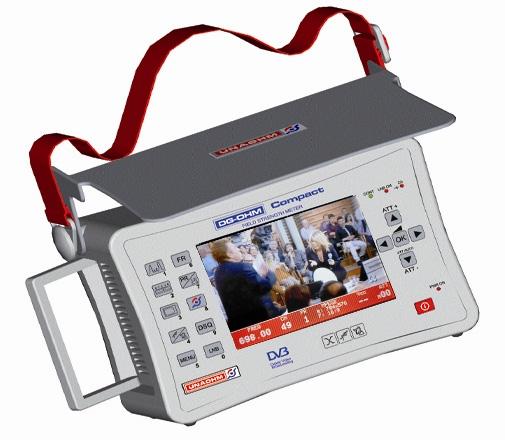
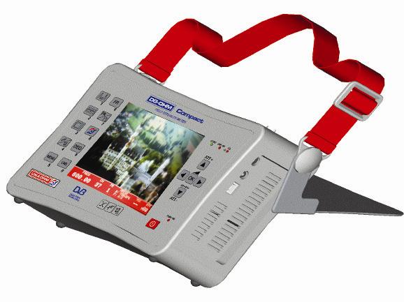
8 2.2 MAIN CHARACTERISTICS Spectrum analyzer: real time total coverage from 45 to 2250 MHz Digital measurements: BER, MER, NM, etc. for standard digital DVB-T/T2, DVB-C, DVB- S/S2 Clear SD and HD picture viewing Constellation diagram LTE function: LTE signal interference analysis toward DVB-T channels. TP SAT function: automatic direct recall tuning of transponders. AER function: echoes analysis for terrestrial signals. CLC function: cable length calculation from the fault point (in combination with external noise generator). DATA LOGGER function: instant, UHF, Satellite. Diseqc: 1.1, 1.2(motor), 2.0, SCR. 2.3 MECHANICAL CHARACTERISTICS Holder: ABS polymer Innovative solutions: multi-function tilting cover: o Closed: used for protection during transport. o Adjustable opening: to further protect from sunlight. o Flap opening: as a pedestal for secure support. transport strap for safe use with hands free. side handle for transport and safe handling. Monitor: Professional colour 5.7" LCD with wide viewing angle and back light control Weight: less than 2 Kg Size (cm): 24(L) x 16(A) x 9(P) Li-Ion battery autonomy: autonomy over 5 hours, fully charged in 4 hours USB port: PC connection for firmware updates and download of measurements stored with the data logger (also with any software for remote control) RCA video input: to test decoder and video camera video signals. DG-OHM UNAOHM TECHNOLOGY 6
9 3.0 TECHNICAL SPECIFICATIONS Characteristic DG-OHM HD DG-OHM FULL HD Real time spectrum analyzer Frequency band MHz MHz DVB-T DVB-T2 - DVB-H DVB-C - DVB-S DVB-S2 MPEG4 MPEG2 NIT Constellation diagram DiSEqC 1.1, 1.2, , 1.2, 2.0 SCR LTE analysis Echoes analysis Data Logger Length calculation from the cable fault point Automatic terrestrial channel search USB port 5.7 colour high brightness LCD Dimensions 24 x 16 x 9 cm 24 x 16 x 9 cm Weight 2 kg 2 kg Li-Ion battery autonomy 5h 5h Measurement precision ± 1.5 db ± 1.5 db Voltage supplied by BNC 0V, 13V, 18V 0V, 13V, 18V Attenuator auto / man step 10dB auto / man step 10dB 3.1 SUPPLIED ACCESSORIES 1 External network power supply. 1 Li-Ion 4.5 Ah battery. 1 Instructions manual 1 Instrument container case. 3.2 OPTIONAL ACCESSORIES NG 500 External noise generator. FCV GHz Down converter. Professional transport carrying case. DG-OHM UNAOHM TECHNOLOGY 7
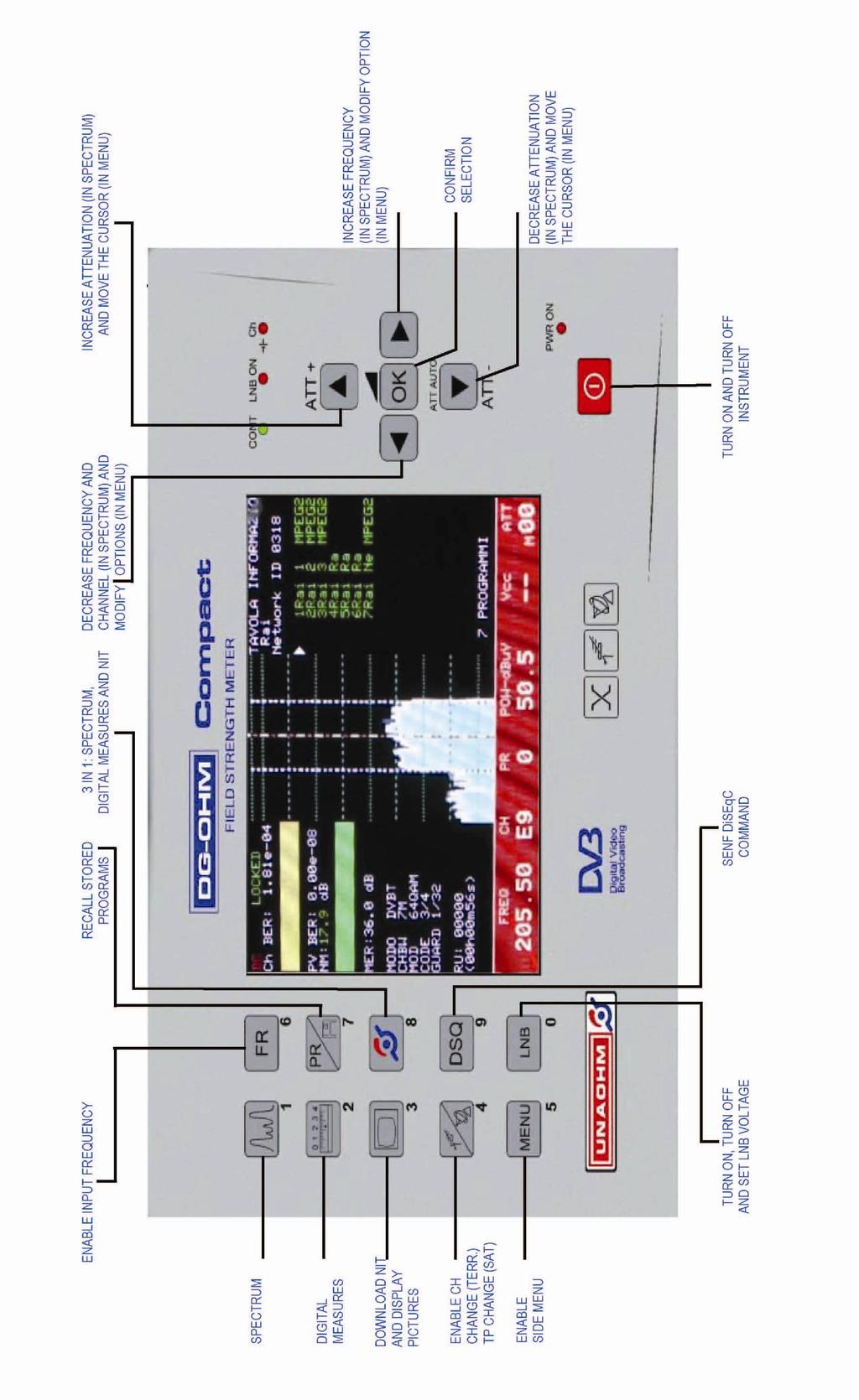
10 4 KEYBOARD Button Single Press Press and Hold Spectrum Modifies spectrum expansion Activates frequency entering Digital measurements Stored programme recall NIT download and picture viewing 3 in 1: spectrum, digital measurements and NIT Activates modifications of terrestrial CH and satellite TP Sends DiSEqC command Activates side menu LNB On/Off and voltage regulation In spectrum, increases attenuation and in menus, moves the cursor In spectrum, decreases frequency and channel and, in menus, modifies options Confirms selection Changes frequency increase digit OFDM / QAM selection (for FULL HD only) Programme table TV menu On the digital screen, stores instant measurements and, in spectrum, opens Data Logger Switches terrestrial / satellite band DiSEqC menu Activates main menu Menu with LNB settings Fast decrease Adjustments menu In spectrum, increases frequency and Fast increase channel and, in menus, modifies options In spectrum, decreases attenuation and in menus, moves the cursor Automatic attenuator Instrument On/Off STATUS BAR The status bar at the bottom of the screen superimposes all main information for constant viewing. You can make it transparent in TV pictures mode by simply pressing (single click) the button and modifying the BLACK or TRANSPARENT choice in the box. In addition, the status bar will change colour depending on the environment to be measured: 1. Red: power measurements for digital terrestrial. 2. Green: level measurement (CHBW: 1 MHz) for terrestrial band analogue signals. 3. Light blue: level measurements for satellite band analogue signals. 4. Blue: power measurements for digital satellite. Frequency Channel/tpsat programmes Power/level Vcc (voltage) ATT DG-OHM UNAOHM TECHNOLOGY 8
11 5 INSTRUCTIONS FOR USE 5.1 POWER The DG-OHM Compact can be powered 3 ways: voltage alternating from 90V to 260V by means of included external power supply Li-Ion battery which, when fully charged, has an autonomy of more than 5 hours external continuous voltage between 11.5V and 15V with current of at least 3A 5.2 START-UP AND SHUT DOWN The instrument turns on and off by holding down the button for a few seconds. 5.3 BATTERY USE The battery charges while the instrument is in stand-by with the power on. 2 LEDs which switch on depending on charging conditions are found on the front of the instrument, above the button: red LED on: instrument off with charging battery green LED on: instrument off with battery fully charged LED off: instrument on Some important notes on battery use: Before using new batteries, it is a good idea to perform three complete charging and discharging cycles. To view the battery charge status and therefore residual autonomy, see the battery icon on the upper left of the screen. When the battery charge is low, the icon will become red before the instrument switches off. At this point, we recommend interrupting use of the instrument and recharging the battery as soon as possible. If you continue to use the instrument (5-10 minutes max), the instrument will switch off. When the equipment remains inactive for long periods, we recommend charging the battery at least once a month to prevent deterioration. We recommend switching on the instrument at least once a month for a few hours. 5.4 PREPARATION FOR START-UP Upon start-up, the instrument returns to the same conditions of use at the last shut down if it was shut down using the button, with the following exceptions: Power supply voltage (for safety reasons) in output from the input connector RF IN is always excluded whenever TPSAT is not used. The measurement status of the digital sections QPSK, OFDM or QAM is not restored. Each time a button is pressed a short acoustic tone is heard in confirmation of the operation. To mute the "beep," press the button, position the cursor on BUZZER and select OFF. DG-OHM UNAOHM TECHNOLOGY 9
12 6.0 TUNING 6.1 TERRESTRIAL TUNING Terrestrial tuning can be carried out by frequency, channel or programme. In order to select a mode press the corresponding button: 1. Single click the button to activate the programme mode, allowing navigation (by means of the programme. buttons or setting a number from the numeric keypad) by 2. Single click the button to activate the channel mode, allowing navigation (by means of the buttons or setting a number from the numeric keypad) by channel. 3. Single click the button to activate the frequency mode, allowing navigation (by means of the frequency. buttons or setting a number from the numeric keypad) by Regardless which mode has been selected, when you directly set a frequency, channel or programme, when the relative button is pressed, the message "123" will appear on the upper left of the screen to alert the user that he can select the numerical value by means of the keyboard, which has now been transformed into a numeric keypad, and then confirm with the OK button. It is also possible to tune the frequency setting simply by modifying the digit or step (thousands, hundreds, tens, units, tenths, hundredths of MHz) of increase or decrease. To modify the step: press and hold the modified with the the digit using the 6.2 SATELLITE TUNING button, position the cursor on the digit to be buttons, confirm the step to be modified with the OK button, modify buttons. Satellite tuning can be carried out by frequency, transponder (TP-SAT) or programme. In order to select a mode press the corresponding button: 1. Single click the button to activate the programme mode, allowing navigation (by means of the programme. buttons or setting a number from the numeric keypad) by 2. Single click the button to activate the transponder (TP-SAT)mode, allowing navigation (with the buttons), directly recalling all transponder settings (L.O. frequency, high or low band polarity, digital parameters). 3. Single click the button to activate the frequency mode, allowing navigation (by means of the frequency. buttons or setting a number from the numeric keypad) by DG-OHM UNAOHM TECHNOLOGY 10
13 Regardless which mode has been selected, tuning is to be carried out with the increase or decrease keys. Otherwise, set values using the numerical keypad, confirming with the OK button AUTOMATIC SATELLITE TUNING FOR TRANSPONDER (TPSAT function) TRANSPONDER tuning (automatic mode) provides HOT BIRD 13 EST satellite as a default setting. Should the need arise to change the satellite on which you are navigating in automatic mode, proceed as follows: 1. press and hold the button to activate the TV menu 2. press OK on "Satellite" 3. move the cursor using the buttons on the satellite to be selected and press OK 4. Single click on the button to exit from the TV menu. 5. In this way, the instrument will return to spectrum analyzer mode, allowing navigation by transponder, by means of the (increase and decrease) keys of the previously selected satellite (the symbol will indicate the selected satellite). TV MENU SATELLITE TAB. CHANNELS LTE SOURCE Eutelsat 16 E Hot bird 13 E Astra 19.2 E Hellas MANUAL SATELLITE TUNING Alternatively, you can use the manual (professional mode) procedure to enter the following parameters: 1. Local oscillator: from the spectrum analyzer mode ( ), single click on the button to activate the side menus. Select the last box; press OK to select modify. Use the (increase and decrease) buttons to modify the setting: OL1, to set low satellite band frequencies (frequencies lower than 11750). OL2, to set high satellite band frequencies (frequencies exceeding 11750). IF, to set satellite frequencies converted in IF (from 900 to 2250). 2. Frequency: press the button. The message "123" will appear on the upper left of the screen to alert the user that he can enter the frequency value with the keyboard, which has now been transformed into a numeric keypad, or else with the increase and decrease buttons. It is also possible to tune the frequency setting simply by modifying the digit or increase or decrease step (thousands, hundreds, tens, units, tenths, hundredths of MHz). DG-OHM UNAOHM TECHNOLOGY 11
14 To modify the increase step: press and hold the digit to be modified with the button, modify the digit using the button, position the cursor on the buttons, confirm the step to be modified with the OK buttons. 3. Satellite polarity: single press the button to activate or deactivate output voltage and make the Vcc camp active in the status bar, which will flash. Use the increase and decrease keys to select the 4 polarities: VL vertical low (13Volt) HL horizontal low (18 Volt) VH vertical high (13Volt + 22KHz). HH horizontal high (18Volt + 22KHz). (ATTENTION: in terrestrial, voltages 0Volt, 13Volt, 18Volt will be enabled to power external devices such as pole control units, etc.) 4. Symbol rate: from the digital screen, single click on the button to activate the side menu. Select the PARAMETERS box. Using the (up, down) buttons, press ; the cursor will move to SYMB. R.. Subsequently, press to move the cursor to the right on the numerical value of the symbol rate and, using the keyboard which has converted into a numerical keypad, you can enter the value of the new symbol rate. 7.0 ATTENUATOR If the signals measured by the MARKER exceed or are less than the values detected by the instrument in its current conditions, this situation will be signalled with the appearance of a > (greater than) or < (less than) symbol, indicating the need to insert or remove attenuation cells allow correct reading of the signal level or power. It is possible to manually act on attenuators using the following keys: 1. : ATT+ : will add an attenuation cells at steps of 10 db 2. : ATT+ : will remove attenuation cells at steps of 10 db It is, however, possible to use the AUTOMATIC ATTENUATOR. This activation will enable the instrument to automatically calculate the attenuation cell to measure level or power. To activate, press and hold the button from spectrum analyzer mode. The attenuation cell value will be indicated in the status bar under ATT. DG-OHM UNAOHM TECHNOLOGY 12
15 STATUS BAR: Frequency Channel/tpsat programmes Power/level Vcc (voltage) ATT MENU Some buttons, when pressed and held, activate a menu relative to the button which permits further operations to be performed. 8.1 MAIN MENU Press and hold the MAIN MENU Configuration Loc. Oscillator Language Buzzer Spectrum (menu) button to activate the main menu. Displays all information on SW versions, HW components present, S/N, etc. Permits the setting of pre-defined L.O. or USER L.O. Language selection (Italian, English, French, German, Spanish) Activates or deactivates the beep heard when keys are pressed Sets the spectrum as: classic, line, combined 8.2 DIGITAL MENU Press and hold the (digital measurements) button to activate the selection menu. MODE OFDM QAM Activates the COFDM board for DVB-T; DVB-TS (full hd only) digital terrestrial measurements. Activates the QAM board for DVB-C (full hd only) for digital measurements via cable. 8.3 TV MENU Press and hold the TV Satellite Channels table LTE Source (TV) button to activate the selection menu. Displays satellite list (TPSAT) in order to select the one that will be used in SAT mode. To view and select the suitable channel table (Italy default) Activates specific LTE function to better control filter functionality and the coexistence of digital terrestrial signals with LTE signals. Allows the selection of video input for decoder testing or EXT video camera selection. DG-OHM UNAOHM TECHNOLOGY 13
16 8.4 DiSEqC MENU Press and hold the (DSQ) button to activate the DiSEqC menu. DiSEqC MENU 2 way DiSEqC Sets and transmits commands to switch DiSEqC on 2 satellites. 4 way DiSEqC Sets and transmits commands to switch DiSEqC on 4 satellites. DiSEqC Level Sets the DiSEqC level between: 1.0, 1.1, 2.0 List Opens the DiSEqC list with all available commands Motor 1.2 Allows the user to move, drive or manage a DiSEqC motor. DiSEqC SCR Activates the SCR function for control of the LNB SCR 8.5 PROGRAMME MENU Press and hold the DiSEqC is a registered trademark of EUTELSAT. (PR) button to activate the programme management menu. 8.6 LNB MENU Press and hold the (LNB) button to activate the selection menu. LNB Step Amperes Auto recovery Sets the 4 polarities for driving the LNB (VH, VL, HH, HL) Activates amperometric mode: measures absorption of devices connected to the BNC Automatic function for short-circuit resolution 8.7 DATA LOGGER MENU Press and hold the button to activate the selection menu. DATA LOGGER Instant Allows viewing of instant measurements UHF Allows start-up or viewing of the UHF DATA LOGGER (from CH 21 to CH 60) Satellite Allows start-up or viewing of the Satellite DATA LOGGER (for the stored TPSAT) DG-OHM UNAOHM TECHNOLOGY 14
 To help better remember the order of the three phases, please note that the numbers associated with the button precisely follow the order of the")
17 9.0 TERRESTRIAL ANTENNA INSTALLATION The pointing of a terrestrial antenna must be carried out in 3 different phases: 1. POINTING (phase 1 button) 2. OPTIMISATION (phase 2 button) 3. CLEAR NIT AND TV PICTURES VIEWING (phase 3 button) To help better remember the order of the three phases, please note that the numbers associated with the button precisely follow the order of the phases. 9.1 POINTING (phase 1 button) The first pointing phase has the task of identifying the direction from which digital terrestrial signals are received and, at the same time, thanks to the spectrum in real time, to search for the antenna position that will get the most amount of signals, or rather the most power. The field meter must be set to spectrum analyzer mode,, initially entering the FULL spectrum viewing mode (press to change from SPAN to FULL). This will allow us to pinpoint the location of the repeater. Next, select a specific channel, to be chosen from the importance of MUX content (paid channels or guaranteed channels such as RAI, Mediaset) or choose another low quality channel. In the latter case, obviously improving the quality of a poor quality MUX, other channels arriving from the same direction can benefit or at least not suffer. The fact remains that, in many cases, pointing is also a position compromise that must meet the requirements of the involved MUX. Once a channel or specific MUX has been set, you will need to modify the SPAN. Press and hold the button to set SPAN from FULL to as preferred. This operation will allow us to zoom in on the signal to improve its pointing. In fact, by means of small movements on the antenna, you can try to get a MUX that is powerful and squared. This operation will allow us to perform pointing for the most power possible. Picture of the real time spectrum analyzer representing the captured MUX. DG-OHM UNAOHM TECHNOLOGY 15

18 9.2 OPTIMISATION (phase 2 button) Once the first phase of pointing to maximum power has been performed, now we have to carry out a second step to optimise the quality. In fact, for digital signals, we do not always improve the quality with quantity; this is why we carry out pointing for the quantity and then, later, optimisation for quality. Press the button to activate the COFDM board, which will perform BER, MER, etc. quality measurements. In this phase, we will have to make small movements on the antenna to find the position that guarantees the best BER, MER and NM. Digital signal quality is highlighted not only in numbers (ex. 1 e- 5, meaning error out of 100,000 symbols), but also through the quality bar image which will get longer as quality improves, or which will become shorter as quality gets worse, until the signal is so degraded in quality that it will give the "NO CARR" or UNLOCKED" message, or the complete absence of quality. In addition, the quality measurement bars can light up three different colours to give an immediate idea of the quality: GREEN optimal condition of errors (few) YELLOW fair condition / some errors RED critical condition of errors Once signal quality has been optimised, our quantity may have decreased, but this will not influence our situation negatively. Picture of the terrestrial digital screen button. LOCKED: SIGNAL LOCKED ON UNLOCKED / NO CARR: SIGNAL NOT LOCKED ON : due to poor quality or absence of signal, no TV pictures can be seen. Ch BER: BER channel measurement (bit error ratio, or rather the number of bit errors over time). Pv BER: Post Viterbi BER measurement (bit errors over time after the correction of Viterbi). MER: Modulation error ratio (errors on modulation) NM: Noise Margin (guarantee margin in db). CELL: Recognition code of the repeater from which the signal is being received. RU: Uncorrected errors. DG-OHM UNAOHM TECHNOLOGY 16
 and will allow for selection of a television broadcaster to display clear pictures.")
19 9.3 CLEAR NIT AND TV PICTURES VIEWING (phase 3 button) Once phase 2 has been completed and, therefore, the best quality and quantity signal has been obtained, simply press the button to activate the MPEG4 board, which will communicate the N.I.T. network information table (list of channels contained in the MUX) and will allow for selection of a television broadcaster to display clear pictures. In NIT mode, press the button (single click), select TRASPARENT mode to have the words superimposed on the pictures, or select BLACK to have the black background with no images behind. To select the viewing of a television broadcaster, from the NIT screen, simply use the button to move and then single press the button to see the clear digital pictures. Clear digital terrestrial TV mode picture From the digital TV screen, press the button to recall the side menus which will allow: STATUS B. CHANNEL INFO AUDIO DIGITAL MEASUREMENTS Status bar management: Activates/deactivates (full screen viewing) Select the broadcaster and relative information: channel name, video PID, audio PID To select audio for that channel View the main digital measurements together with pictures Management of adjustments such as brightness, contrast, volume by pressing and holding the button which will activate the control bars. Use the keys to select the various settings: VOLUME (only in TV mode) CONTRAST BRIGHTNESS Use the keys to increase or decrease relative contents. DG-OHM UNAOHM TECHNOLOGY 17
 To help better remember the order of the three phases, please note that the numbers associated with the button precisely follow the order of the")
20 10.0 SATELLITE DISH INSTALLATION The pointing of a satellite antenna must be carried out in 3 different phases: 1. POINTING (phase 1 button) 2. OPTIMISATION (phase 2 button) 3. CLEAR NIT AND TV PICTURES VIEWING (phase 3 button) To help better remember the order of the three phases, please note that the numbers associated with the button precisely follow the order of the phases. Press and hold the button to switch from terrestrial to satellite and vice versa. Once you have switched to the satellite range (BLUE status bar), the pre-stored TRANSPONDERS will already be active in the status bar. Press the key to select the desired Transponder POINTING (phase 1 button) Set a SPAN value, press and hold the button to obtain a zoom on a specific signal. Now, simply position the satellite dish with elevation appropriate to the location. Next, move the satellite dish horizontally to capture the searched satellite. Thanks to the REAL TIME SPECTRUM, you will simply need to move the satellite dish horizontally until the MARKER positions in the middle of the received signal, as shown below. In this situation, the TP will not necessarily be exactly the desired satellite, because there may be TP with parameters similar to ours but of other orbital positions. Therefore, once you are in the above-indicated situation, make sure that the signal is LOCKED, pressing the button. If the signal locks, regardless of the quality (but without RU) press the button, which will download the NIT and, in particular, the orbital position that we are going to compare with the one in question. If they match, we have pointed the right satellite. Next, we will have to carry out an optimisation phase to obtain the best quality. DG-OHM UNAOHM TECHNOLOGY 18

21 10.2 OPTIMISATION (phase 2 button) After verification of the correct satellite dish position by reading the orbital position from the NIT, we will need to optimise signal quality, to ensure viewing even in critical conditions, by slightly moving the dish. Digital satellite screen picture. LOCKED: SIGNAL LOCKED ON UNLOCKED / NO CARR: SIGNAL NOT LOCKED ON : due to poor quality or absence of signal, no TV pictures can be seen. Ch BER: BER channel measurement (bit error ratio, or rather the number of bit errors over time). Pv BER: Post Viterbi BER measurement (bit errors over time after the correction of Viterbi). MER: Modulation error ratio (errors on modulation) NM: Noise Margin (guarantee margin in db). CFO: Central frequency offset (indicates the conversion error of the LNB local oscillators) CLEAR NIT AND TV PICTURES VIEWING (phase 3 button) Once phase 2 has been completed and, therefore, the best quality and quantity signal has been obtained, simply press the button to activate the MPEG4 board, which will communicate the N.I.T. network information table and will allow for selection of a television broadcaster to display clear pictures (see paragraph 9.3). DG-OHM UNAOHM TECHNOLOGY 19


22 11.0 SPECIAL FUNCTIONS Model DG-OHM allows users to carry out special functions to particularly analyze further aspects in addition to the measures themselves IN 1 FUNCTION This particular function allows users to obtain a complete analysis on a single screen, both in terrestrial and in satellite. To activate this function, simply position the MARKER at the middle of the MUX or a TRANSPONDER and single click on. The screen specified above will be displayed. The screen will be divided in 3, keeping the real time spectrum analyzer in the middle, with all real time digital measurements on the left side and NIT with all information relative to the signal on the right side of the screen, allowing for overall viewing of all information. This function can also be used for satellite to discover the orbital position of an unknown signal CONSTELLATION To activate a constellation diagram, which will allow for a graphical representation of the quality of the signal, simply single click the button from the digital screen (press ), both terrestrial and SAT. This operation will activate the side boxes, where you can select CONST. Constellation diagram DG-OHM UNAOHM TECHNOLOGY 20

23 11.3 AER (ECHOES ANALYSIS FOR DIGITAL TERRESTRIAL) This function allows ether analysis of mother signal behaviour and of any relative echoes which may disturb or negatively influence the MUX. ECHOES are defined as all those rebounds in ether by the mother signal, which bounce off surface as buildings, lakes, etc. These then tend to get to the antenna with a signal delay with respect to the mother signal. These are defined as destructive ECHOES if their delay with respect to the arrival of the mother signal (the most powerful) exceeds the time known as the guard interval. Non-destructive ECHOES are those whose delay times remain within the guard interval. GUARD INTERVAL REFERENCE TABLE (8k carrier) GUARD 1/32 1/16 1/8 1/4 MAXIMUM DELAY (µs) MAXIMUM DISTANCE (Km) To activate the echoes analysis: press the the signal has been LOCKED, press the button to switch to quality measurements. Once button to open the side box. Select AER and press. On the AER screen (photo above), you can press the button to activate the side menus for further management or viewing of the quality measurements (BER, MER ). As you can see in the photo, the mother signal (the most powerful) will be highlighted, automatically placing a yellow marker. The two markers at the end show the guard interval; therefore, any echoes inside this area are not destructive, as they remain within the guard interval. Vice-versa, any signals outside this area can be destructive, as they go outside the guard interval. The red marker allows us to highlight any echoes and get information: DS (delta space): identifies the distance of any echoes. DT (delta time): identifies the delay of any echoes. GUARD MKR: indicates the time limit of the guard interval. DG-OHM UNAOHM TECHNOLOGY 21


24 11.4 CLC FUNCTION (DISTRIBUTION CONTROL, LENGTH CALCULATION FROM THE CABLE FAULT POINT) This function calculates the distance of a fault on a cable due to impedance mismatch. Such defects, caused by distribution, may depend on an open, bent, or generally ruined cable. To use the CLC function, you will need to work with a noise generator and set the DG-OHM in spectrum analyzer mode, button. 1. Connect the instrument input BNC to a noise generator by means of the T-connector. 2. Activate the noise generator. 3. Attenuate the signal in order to put it in a readable scale (using the buttons) or activate the automatic attenuator (press and hold ). 4. Connect the distribution cable to the T-connector. 5. If distribution presents an impedance mismatch, linearity will not be seen on the spectrum, but valleys or holes. 6. Set the SPAN with a value suitable for obtaining 2 valleys on the screen (press and hold ). Point the first market on the first valley or hole. 7. Activate the CLC functions: single press to open the side boxes. Select CLC ON and press to deactivate the side menus. 8. Move the second marker (using the keys) in frequency until you find the next or previous valley or hole. 9. Read the distance of the impedance mismatch as follows: PEE: distance by mismatched expanded cables. PE: distance by mismatched compact cables. Point 5 Point 6 Point 7 ; point 8 DG-OHM UNAOHM TECHNOLOGY 22
25 11.5 SCR FUNCTION 1. Set the field meter to satellite frequency range (press and hold ) and in spectrum analyzer mode ( ). Press and hold the to activate the menu. Select DiSEqC SCR and confirm with. Select MONO FEED and press. DiSEqC 2 WAY DiSEqC 4 WAY DiSEqC DiSEqC Level DiSEqC User MOTOR (1.2) DiSEqC SCR MONO FEED DUAL FEED 2. Select 1 of the 4 frequencies relative to the 4 SCR channels and press. DiSEqC SCR SCR A : 1,210 MHz SCR B : 1,420 MHz SCR C : 1,680 MHz SCR D : 2,040 MHz SCR E : USER 3. After selecting one of the 4 channels to check, the instrument will return to the SPECTRUM mode indicating SCR at the top right in order to signal the particular mode of use. 4. To check correct operation of the selected SCR channel, you can use the pre-stored transponders or else the parameters of the desired transponder must be manually set as follows: a. Set TRANSPODER frequency with the local oscillator and not 1IF frequencies, for example TP124 RAI, type and not 1.242,00. Then press and enter the numerical sequence followed by. b. Set the polarity through the side menu ( ) POL V or POL H. DG-OHM UNAOHM TECHNOLOGY 23
26 c. Select TRANSMIT from the side menu to send the request to the SCR LNB made up of: TRANSPONDER FREQUENCY POLARITY V (VERTICAL) If the LNB is operational on that channel (A, B, C, D), the selected transponder (TP) on the spectrum will be seen cut in half by the MARKER. This way, we will have correctly selected its recall for frequency and polarity, therefore the check its quality as also takes place for classic use we will press to measure quality (BER MER etc.) and then to download the NIT and view the images. In SCR mode, if the functions: button is pressed, the side menu appears which allows further SCR A POL V TRANSMIT >> SPAN 6 EXIT Selection of the 4 SCR channels A-B-C-D Polarity setting V= vertical ; H= horizontal Send request to the SCR LNB Select for spectrum view: SPAN-FILTRO-V.FILTER-MKR Exit the SCR mode to return to classic use. ATTENTION: Due to the diversity of SCR LNB technology with respect to the classic universal LNB, pay close attention to the following points: 1) Programme memories cannot be used for SCR. 2) To set the frequency, we recommend using a numeric keypad as indicated above. Increasing with the buttons may be slow, as the transponder frequency setting is not made by the internal tuner of the field meter, but by the LNB SCR, which receives the request from the instrument and then modifies it and responds later. 3) The vertical/horizontal polarity is no longer recalled by means of varying LNB voltage (13Volt = vertical, 18Volt=horizontal), but will form part of the package that we will send to the LNB SCR frequency, such as V = vertical or H = horizontal. 4) To obtain the high band, we no longer activate the 22KHz, since it will be the LNB SCR itself to understand by means of the transponder frequency we will send. a. Fr TP < 11,750 low band. b. Fr TP > 11,750 high band. DG-OHM UNAOHM TECHNOLOGY 24

27 11.6 LTE The LTE function will analyze the best coexistence of digital terrestrial signals with the latest LTE signals which, because of their frequency and power, without proper protection would risk interfering with the last available MUX DVB-T. This function will help to calibrate the LTE signal protection filters or to assess any performance of those used. To activate the LTE function, press and hold, select LTE and press. The instrument will automatically set the SPAN values and more selective filters to analyze the best of their coexistence. The markers will then automatically be positioned on the frequencies of channel 60 and channel 61, activating continuous calculation in real time, comparing the power of channel 61 to that of channel 60. LTE communicates the resulting ratio between the two signals in real time: LTE > 30 critical condition (filter not working properly or absent) LTE just under 30 (filter working just enough) LTE < 25 (filter working very well) DG-OHM UNAOHM TECHNOLOGY 25
28 12.0 PROGRAMME MEMORIES The DG-OHM model allows the user to save 50 programme memories, from PR00 to PR49, mixed between satellite and terrestrial as desired. The saved programme memory can be read or recalled in the status bar under PR SAVING PROGRAMME MEMORIES To save a programme memory, proceed as follows: 1. Set the instrument to spectrum analyzer mode ( ). 2. Tune and set the instrument with the parameters to be saved (frequency, LNB voltage channel, digital parameters, etc.). 3. Press and hold. The table of programmes will appear and will allow the user to manage programme saving and deleting. 4. Single click to exit from the programme table PROGRAMME TABLE Press and hold (in spectrum analyzer mode) to activate the programme table. The status relative to programme content to be saved will be indicated in the first table at the top. Terrestrial programme: STATUS: ** 49 (ITA) DVB-T 8M OFF Channel Frequency Standard Chbw Voltages Satellite programme: STATUS: ** 110/13.0E DVB-S VL Transponder Frequency Standard Symbol rate Polarity Use to select where to save the programme. Use to highlight the SAVE / DELETE field. If the memory is free, SAVE will be indicated to save the memory in that position, while if the position is already occupied, DELETE will be indicated. Use to implement SAVE/DELETE. To overwrite an already occupied programme, simply delete it and then save new content in that position. Use Single click to return to navigating programme positions. to deactivate the programme table. DG-OHM UNAOHM TECHNOLOGY 26
29 PR POSITION CHANNEL/TP FREQUENCY STANDARD CHBW/SYMBOL R. POLARITY PR CH / TP FREQ TYPE BW / SR POL 0 49 (ITA) DVB-T 8M OFF DELETE 1 124/13.0E DVB-S VH DELETE 2 SAVE 3 OFF DVB-S HH DELETE 4 E DVB-T2 7M OFF DELETE 12.3 PROGRAMME RECALL To recall programme memories, single click, then the message 123 will appear on the upper right, and the relative PR field will flash. It will be possible to select the programme memory number using the numerical keypad, then confirming by pressing. Press to decrease or increase the memory selection DATA LOGGER Press and hold to activate the DATA LOGGER management menu (see par. 8.7), to select from INSTANT, UHF, SATELLITE. The DATA LOGGER function allows the user to carry out a series of automatic measurements, then saving the relative data in special DG-OHM memories. After having detected and measured within an instrument memory, you will then later be able to download them onto a PC using special remote control software, downloadable from our website From here it will be possible to obtain reports or certifications regarding your television system INSTANT DATA LOGGER The INSTANT DATA LOGGER allows the user to save all measurements (Power, BER, PVBER, MER etc.) relative to the MUX or TRANSPONDER being analyzed and that is active at that moment. Simply press and hold from the digital screen (press ), up to a maximum of 50 instant memories mixed between MUX and TRANSPONDERS. Once the measurements have been saved, the information containing the INSTANT DATA LOGGER position in which measurements have been saved, or the first available, will appear on the middle bottom of the screen. DG-OHM UNAOHM TECHNOLOGY 27
30 To read all measurements saved in the INSTANT DATA LOGGER, activate the DATA LOGGER menu (press and hold ), select INSTANT and press under DATA DISPLAY. The table for managing and/or viewing the INSTANT DATA LOGGER will be displayed UHF DATA LOGGER The UHF DATA LOGGER has been designed to measure and save all measurement values (Power, BER, PVBER, MER, etc.) relative to the UHF range, or rather from channel 21 to channel 60, allowing a maximum of 3 acquisitions for the entire UHF frequency range. To start up full UHF acquisition, proceed as follows: 1. Set the instrument to spectrum analyzer mode (single click ). 2. Press and hold to open the DATA LOGGER menu. 3. Use to select UHF and press. 4. Select one of the 3 possible acquisitions where data will be saved and press to start up the measurement cycle from CH21 to CH60. DATA LOGGER Instant UHF START LOGGER 1 Satellite VIEW DATA 2 To verify measurements made, select VIEW DATA with relative 1,2,3 acquisition. The DATA LOGGER table will be activated, allowing you to view saved data. POSITION CHANNEL STANDARD MUX POWER. Nr. CH DVB POW BER PVBER MER NM CELL 0 21 (ITA) T e-4 0.0e (ITA) T e-6 0.0e (ITA) T e-5 0.0e (ITA) T e-3 0.0e (ITA) T (ITA) T e-2 4.2e Dashes in place of measurements will appear when the signal is too critical and has not even been locked (UNLOCKED or NO CARR). 3 Single click to exit from the DATA LOGGER menu. DG-OHM UNAOHM TECHNOLOGY 28
31 13.3 SATELLITE DATA LOGGER The SATELLITE DATA LOGGER has been designed to measure and save data (Power, BER,PVBER, MER, etc.) relative to the main transponders of the satellite (TPSAT) active in the instrument. If you should want to activate the DATA LOGGER for another satellite, proceed as per paragraph and start up acquisition as follows: 1. Set the instrument to spectrum analyzer mode (single click ). 2. Press and hold to open the DATA LOGGER menu. 3. Use to select SATELLITE and press. 4. Select one of the 3 possible acquisitions where data will be saved and press to start up the measurement cycle relative to the active TPSAT transponders. DATA LOGGER Instant UHF Satellite START LOGGER 1 VIEW DATA 2 To verify measurements made, select VIEW DATA with relative 1,2,3 acquisition. The DATA LOGGER table will be activated, allowing you to view saved data. 3 POSITION Transponder STANDARD TP POWER Nr. TP/FR DVB POW BER PVBER MER NM CFO 0 124/13.0E S e-4 0.0e /13.0E S e-6 0.0e /13.0E S e-5 0.0e /13.0E S /13.0E S e-2 1.5e Dashes in place of measurements will appear when the signal is too critical and has not even been locked (UNLOCKED or NO CARR). Single click to exit from the DATA LOGGER menu. DG-OHM UNAOHM TECHNOLOGY 29
32 14.0 FIRMWARE UPDATE VIA PC To update the DG-OHM field meter, you will have to download and install (only for first update) the UPLOADER software (which will then have to be kept in the PC for future updates) from the website DOWNLOAD section. This software will have the task of interfacing between the PC and the DG-OHM. You will also have to download and install USB drivers for the operating system present on your computer (XP, Vista, Windows 7), so as to have a virtual COM port to use for connection between the devices. At the next update, you will not need to download previous files but will simply have to download the new firmware version for installation (i.e. dg1.1.upg) in the instrument. 1. USB DRIVER INSTALLATION Download the USB driver file. Extract the zip file contents and save them on the desktop or in a folder (as with the file uploader). Connect the instrument to the PC with a cable. The message New hardware found will appear on the computer. Select the message Installation for experts and select the folder with the USB drivers. Wait for an alert of automatic recognition of the end. The new HW is ready for use. Attention! ALWAYS USE THE SAME USB PORT. Repeat the drivers procedure whenever using a different port. If you do not know which COM(xx) port to use, you can verify the type on your computer, from the HARDWARE - DEVICE MANAGER - COM and LPT PORTS control panel. 2. DG-OHM FIRMWARE UPDATE Switch off the instrument and connect it to the home network. Download the *.upg file for the instrument FROM WEBISTE download section. Connect the instrument (switched off) to the PC via USB cable. Start up the uploader programme. Select the COM port from the uploader programme. Switch on the instrument and, after a few seconds, you will see the message INSTRUMENTS ON LINE. Then, the preliminary version of the firmware BOOTLOADER VER.x.y will be detected. Select the *.upg downloaded from the website Select.Start. on the uploader programme. To verify proper updating, wait for the message: Verification Successful: update completed correctly. Verification failed: update not completed correctly. Click on Restart in the uploader programme to re-start the instrument. Close the uploader programme and disconnect the instrument. If you encounter problems during the upgrade, repeat the operation. If problems persist, contact UNAOHM technical support. DG-OHM UNAOHM TECHNOLOGY 30
33 14. WARRANTY The conditions of warranty are stated in the GENERAL CONDITIONS OF SALE" available for consultation at Revision operations are carried out by Technical Support at our facility located at Via G. Di Vittorio, Peschiera Borromeo (Milan), where the units must be sent. Shipment must be carriage unpaid with adequate packing, preferably in the original packing in order to prevent damage during transportation. In order to take advantage of the warranty a copy of the invoice or fiscal sales receipt relative to the purchase of the instrument must be produced. The warranty will be considered void in case of tampering, modifications or repairs carried out by unauthorised personnel. The power batteries and piles are not included in the warranty. SERVICE NOT COVERED UNDER WARRANTY We are available for our esteemed customers for the repair of instruments manufactured by us, even after the warranty period, to restore the equipment to its original condition (as long as it is economically convenient). The availability of mechanical and electronic spare parts is guaranteed for up to 5 years when the circuits are manufactured with discreet components. In the event integrated circuits are used, the supply of replacement parts is ensured while our supplies last and subject to their availability on the global market. The repair of instruments which are no longer covered under warranty is normally carried out against payment. Any request for an estimate must be done expressly upon delivery of the instrument. In the event that the estimate is not accepted, the expenses sustained by us for preparation of the same will be charged to the customer (fixed fee). In order to prevent pointless loss of time it is very important that the equipment is returned with accompanying documents and with its technical data sheet, filled out entirely, available from the support section of the website RECOMMENDATIONS It is always advisable in the event of a possible instrument fault to contact the service department toll-free at to verify the actual presence of a defect with a technician, to avoid the unnecessary sending of instruments, costing time and money to both customers and the company itself. MISCELLANEOUS The electrical diagram of the equipment is not provided (not even on request). Any illustrations and diagrams inserted in the brochure are purely indicative. We reserve the right to make any change which may become necessary without updating the instruction manual. DG-OHM UNAOHM TECHNOLOGY 31
COMPANY PROFILE. Business The company s activities concern several fields of electronics and telecommunication and are divided as follows:
 COMPANY PROFILE Founded in Milan in 1935, UNAOHM is one of the oldest manufacturers of measuring electronic equipments all over Europe. It was born thanks to two young engineers, Mr Enzo Pontremoli and
SATFINDER 3 HD SLIM USER GUIDE
 SATFINDER 3 HD SLIM USER GUIDE INDEX General Safety..... 3 Key Features..... 4 Panel Keypads... 5 Accesory.. 6 Satellite Search...... 7 Spectrum..... 8 Cross Polarisation... 9 Packet TP Levels.... 9 Multi
Horizon HD-STM. Combo Signal Analyzer TEST REPORT
 TEST REPORT Combo Signal Analyzer Horizon HD-STM can be used intuitively, manual is not needed perfect workmanship optimized for the day-to-day work of an installer gives all the "Must-Have" informations
STM 17 HD. DVB-S2+T2/C Compact Meter. User Manual. Ref R13. CAHORS Digital CS Cahors Cedex 9 FRANCE.
 STM 17 HD DVB-S2+T2/C Compact Meter User Manual Ref 0145131R13 DVB COMBO METER 1. Main Features... 2 2. Buttons and Indicators... 3 3. How to measure... 4 4. Home menu... 5 5. Satellite... 5 5.1 Satellite
PCM-1210 DVB COMBO METER User`s Manual
 PCM-1210 DVB COMBO METER User`s Manual 1. Main Features... 1 2. Buttons and Indicators... 2 3. How to measure... 3 4. Home menu... 4 5. Satellite... 4 5.1 Satellite Measure... 4 5.2 LNB Setting... 5 5.3
ATLANTA ASF 2033HD+ DVB-S/S2 METER. User`s Manual
 ATLANTA ASF 2033HD+ DVB-S/S2 METER User`s Manual Buttons and Indicators... 2 How to measure... 3 Main menu... 4 LNB Setting... 4 Edit Satellite... 6 Spectrum Chart... 7 Constellation... 9 Angle Calculation...
SZU OPERATING INSTRUCTIONS SAT NAVI
 SZU 21-00 O P ER ATI N G I N S T R U C T I O N S SAT NAVI Operation Instructions SZU 21-00 Safety Notes Turn off the receiver or any used power supply before installing, to avoid short-circuit. Installation
HD-CM HORIZON DIGITAL CABLE METER
 HD-CM OFF! Max RF i/p = +17dBm 75Ω Max AC/DC i/p = 120Vrms MENU INPUT ON HORIZON DIGITAL CABLE METER Horizon Global Electronics Ltd. Unit 3, West Side Flex Meadow Harlow, Essex CM19 5SR Phone: +44(0) 1279
SATFINDER4 INTRODUCTION USER GUIDE AND CERTIFICATE OF GUARANTEE
 SATFINDER4 INTRODUCTION USER GUIDE AND CERTIFICATE OF GUARANTEE CONTENTS : General Safety...... 3 Basic Properties.... 4 Front Panel Keys... 5 Back Panel Details 5 Charger Adapters.. 6 Utilization of Satfinder4......
Owner s Manual. Sat-Meter MSK 15. Order No.:
 Owner s Manual Sat-Meter MSK 15 Order No.: 217 100 13 Thank you for choosing our latest and most innovative satellite meter. It has been designed and manufactured to a very high standard and offers a UNIQUE
Operating Manual. DVB-T Meter MFK 16
 Operating Manual DVB-T Meter MFK 16 Preface Dear customer, KATHREIN-Werke KG has made every effort to ensure the accuracy and completeness of this manual. However, no liability can be accepted for potential
AVE HOME FAGOR CVBS TO DVB-T ENCODER MODULATOR. Fagor Electr6nica
 AVE HOME CVBS TO DVB-T ENCODER MODULATOR FAGOR Fagor Electr6nica TABLE OF CONTENTS 1. SPECIFICATIONS... 12 1.1 Product Overview... 12 1.2 Appearance and Description... 12 1.3 Diagram... 13 1.4 Characteristics...
All the functions you need in your hand
 All the functions you need in your hand Rely on H30FLEX for installation and troubleshooting. Robust, light-weight and extremely easy to use. Carry out installation, maintenance and troubleshooting tasks
Satellite locator WS-6933
 R Satellite locator WS-6933 User's Manual English CONTENTS 1. GUIDE...2 1.1 IMPORTANT SAFETY INSTRUCTIONS...2 1.2 UNPACKING...2 1.3 PRODUCT OVERVIEW&ILLUSTRATION...3 2. OUTLINE...4 3. THE MENU OSD INSTRUCTION...5
Table of Contents. 1. Safety Use. 2. General Description. 3. Connection Diagram. 4. Operations and Management. 4.1 Display Status. 4.
 DTM-HD01 Thank you for buying this encoder modulator. Please read this manual carefully to install, use and maintain the encoder modulator in the best conditions of performance. Keep this manual for future
HD RANGER+ Evolution? NO. Revolution!
 Evolution? NO. Revolution! The SIXTH GENERATION field meter FROM PROMAX lite ACTUAL SIZE - 7 SCREEN (APPROX. 155 x 93 mm) Revolutionising the market. Again The largest and brightest display HD RANGER+
HD-TM PLUS HORIZON DIGITAL TERRESTRIAL METER
 HD-TM PLUS OFF MENU INPUT ON HORIZON DIGITAL TERRESTRIAL METER Horizon Global Electronics Ltd. Unit 3, West Side Flex Meadow Harlow, Essex CM19 5SR Phone: +44(0) 1279 417005 Fax: +44(0) 1279 417025 Issue
SATELLITE FINDER SK-3200 USER MANUAL
 SATELLITE FINDER SK-3200 USER MANUAL CONTENTS 1. GUIDE...1 1.1 IMPORTANT SAFETY INSTRUCTIONS... 1 1.2 UNPACKING...1 1.3 PRODUCT OVERVIEW & ILLUSTRATION... 2 2. OUTLINE...4 3. THE MENU OSD INSTRUCTION...5
Be sure to run the vehicle engine while using this unit to avoid battery exhaustion.
 CAUTION: TO REDUCE THE RISK OF ELECTRIC SHOCK DO NOT REMOVE COVER (OR BACK) NO USER-SERVICEABLE PARTS INSIDE REFER SERVICING TO QUALIFIED SERVICE PERSONNE; Please Read all of these instructions regarding
RS232 Connection. Graphic LCD Screen. Power Button. Charger Adapter Input LNB Output. MagicFINDER Digital SatLock Operating Manual
 GENERAL FEATURES Easy-to-understand user-friendly menu and keypad. LNB short circuit protection. Display of Analog Signal Level, Digital Signal Quality with % and Bar, audible notification. Timer Lock,
Digital Terrestrial Alignment & Installation Meter
 Digital Terrestrial Alignment & Installation Meter Instruction Booklet Version 3 - February 2005 www.horizonhge.com Thank you for choosing our latest and most innovative terrestrial meter. It has been
REVOLUTIONISING THE MARKET. AGAIN
 REVOLUTIONISING THE MARKET. AGAIN ACTUAL SIZE - 7 SCREEN (APPROX. 155 x 93 mm) The largest and brightest display HD RANGER+ 7 display is the brightest and largest used in any similar meter with excellent
7880: A new family of TV Meters to meet the requirements of the XXI century!
 7880: A new family of TV Meters to meet the requirements of the XXI century! HEVC H.265 HEVC H.265 decoding Weights less than 3Kg DVB-C/C2 J83B DVB-T/T2 Lite Analogue TV DVB-S/S2, multistream 10 inch panoramic
User Manual. HDMI Modulator Ref & SW Release
 User Manual HDMI Modulator Ref. 8201 & 8202 SW 1.1.1.Release No part of this manual may be copied, reproduced, transmitted, transcribed or translated into any language without permission. Unitron reserves
DUAL TOUCH: RESISTIVE & CAPACITIVE, RESISTANT to RAIN, DIRT & SCRATCHES 6.5 TOUCHSCREEN 16:9 TFT. Bars Scan TV = analog = digital See page 23
 DIGICUBE STC The only completely TOUCHSCREEN analyzer HD MEASUREMENTS SUGGESTED MEASUREMENT VALUES SUN & RAIN PROOF DUAL TOUCH: RESISTIVE & CAPACITIVE, RESISTANT to RAIN, DIRT & SCRATCHES 6.5 TOUCHSCREEN
SM-10 SAT Level Meter User s Manual
 SM-10 SAT Level Meter User s Manual DAGATRONICS CORPORATION 263-1 DUCKIDONG, ILSAN, KOYANG, KYUNGKIDO, KOREA TEL: +82-31-916-8005 FAX: +82-31-916-8080 Email: dagatron@dagatron.com Website: www.dagatron.com
HD Digital Set-Top Box Quick Start Guide
 HD Digital Set-Top Box Quick Start Guide Eagle Communications HD Digital Set-Top Box Important Safety Instructions WARNING TO REDUCE THE RISK OF FIRE OR ELECTRIC SHOCK, DO NOT EXPOSE THIS PRODUCT TO RAIN
Evolution Digital HD Set-Top Box Important Safety Instructions
 Evolution Digital HD Set-Top Box Important Safety Instructions 1. Read these instructions. 2. Keep these instructions. 3. Heed all warnings. 4. Follow all instructions. 5. Do not use this apparatus near
Single cable multiswich programmer PC102W
 Single cable multiswich programmer PC102W 1. Product description The PC102W - single cable multiswich programmer (in the text - programmer) is useful instrument while configuring and troubleshooting SAT
HD-1603 Single Input MPEG-4 DVB-T HD Encoder/Modulator User Guide and Install Manual
 ZyCastR digi-mod HD Range digi-mod HD-1603 www.digi-modbyzycast.com HD-1603 Single Input MPEG-4 DVB-T HD Encoder/Modulator User Guide and Install Manual Table of Contents www.digi-modbyzycast.com Safety
ASF 2050 COMBO USER MANUAL
 ASF 2050 COMBO USER ASF 2050 COMBO USER 1. BUTTONS AND INDICATORS... 2 2. BASIC FUNCTIONS.... 4 2.1 Satellite... 5 2.2Terrestrial... 24 2.3 Cable... 33 2.4 Saving... 41 2.5 System Setting... 42 2.6 USB
CAUTION RISK OF ELECTRIC SHOCK NO NOT OPEN
 Evolution Digital HD Set-Top Box Important Safety Instructions 1. Read these instructions. 2. Keep these instructions. 3. Heed all warnings. 4. Follow all instructions. 5. Do not use this apparatus near
DMOD1200MS. HDMI Modulator. User Manual PLEASE READ THE MANUAL COMPLETELY BEFORE USE V.17.09
 DMOD1200MS HDMI Modulator User Manual PLEASE READ THE MANUAL COMPLETELY BEFORE USE V.17.09 CONTENTS 1. INTRODUCTION 1.1. Product Description 1.2. Package Contents 1.3. Hardware Installation 1.4. Safety
8dtek DSM Desired. Business Voucher Direct Contact to Sales Manager. TELE-satellite Magazine
 TEST REPORT 该独家报道由技术专家所作 Satellite Signal Analyzer 8dtek DSM Desired includes features normally only found in much higher priced products shows constellation and spectrum handles all DiSEqC variants including
Satellite Signal Meter TEST REPORT 该独家报道由技术专家所作. 8dtek DSM Gifted. 30 TELE-satellite Global Digital TV Magazine 06-07/2011
 TEST REPORT 该独家报道由技术专家所作 Satellite Signal Meter 8dtek DSM Gifted 30 TELE-satellite Global Digital TV Magazine 06-07/2011 www.tele-satellite.com measures all tv signals in DVB-S, DVB-S2 and even the old
CM 3S-TC. Triple Transmodulator 8PSK-COFDM/QAM. User manual
 CM 3S-TC 082016 Triple Transmodulator 8PSK-COFDM/QAM User manual 1 1. Accessories... 1 2. General Description... 2 3. Installing and connections... 4 3.1. Installing and general connections... 4 3.2. Installation
Easy-to-use : setup, frequency maps, recorded data can be saved or downloaded from a USB memory stick.
 TV picture : the high quality LCD screen is used to provide TV pictures, SD or HD TV programs, for terrestrial, cable and satellite. Easy-to-use : setup, frequency maps, recorded data can be saved or downloaded
English CONTENTS 1. GUIDE FEATURES THE MENU OSD INSTRUCTION TECHNICAL SPECIFICATION... 7
 USER S MANUAL English CONTENTS 1. GUIDE...2 1.1 IMPORTANT SAFETY INSTRUCTIONS...2 1.2 GENERAL DESCRIPTION...2 1.3 PRODUCT OVERVIEW & ILLUSTRATION...3 2. FEATURES...4 3. THE MENU OSD INSTRUCTION...5 4.
END USER MANUAL DAS-M44HD-R
 END USER MANUAL DAS-M44HD-R Warnings: Important Safety Instructions and Caution Please read all of these instructions regarding your unit and retain them for future reference Read this manual fully and
PROMAX NEWSLETTER Nº 22
 PROMAX NEWSLETTER Nº 22 TV EXPLORER HD series: H.264 / MPEG-4 AVC picture CV-100: Optical LNB adapter for TV EXPLORER MO-370: ISDB-T/T B modulator DIGITAL To TV: for Broadcast and TV Distribution PROMAX-27:
STM 26 HD. DVB-S2+T2/C Compact meter User Manual. Ref R13. CAHORS Digital CS Cahors Cedex 9 FRANCE
 STM 26 HD DVB-S2+T2/C Compact meter User Manual Ref 0145225R13 Preface USER MANUAL Please read this manual carefully before using your Digital Sat meter for the first time. This operating manual will help
IMPORTANT SAFETY INSTRUCTIONS
 IMPORTANT SAFETY INSTRUCTIONS 1. Read, follow and keep these instructions safely. 2. Heed all warnings. 1. Do not use this apparatus near water. 2. Clean only with dry cloth. 3. Do not block any ventilation
DM-1CH SD DVB-T MODULATOR INSTRUCTION MANUAL
 DM-1CH SD DVB-T MODULATOR INSTRUCTION MANUAL 2. Caution Statements and Table of Contents Table of Contents 2. Caution Statements and Table of contents 3. Important Safety Instructions 4. Important Safety
TRANSCENSION 6-CHANNEL DMX DIMMER PACK (order code: BOTE40) USER MANUAL
 USER MANUAL") www.prolight.co.uk TRANSCENSION 6-CHANNEL PACK (order code: BOTE40) USER MANUAL SAFETY WARNING FOR YOUR OWN SAFETY, PLEASE READ THIS USER MANUAL CAREFULLY BEFORE YOUR INITIAL START-UP! CAUTION! Keep this
www.prolight.co.uk TRANSCENSION 6-CHANNEL PACK (order code: BOTE40) USER MANUAL SAFETY WARNING FOR YOUR OWN SAFETY, PLEASE READ THIS USER MANUAL CAREFULLY BEFORE YOUR INITIAL START-UP! CAUTION! Keep this
CompactMax-4 DVB-S/S2 TO ISDB-T TRANSMODULATOR - 0 MI2101 -
 CompactMax-4 DVB-S/S2 TO ISDB-T TRANSMODULATOR - 0 MI2101 - SAFETY NOTES Read the user s manual before using the equipment, mainly "SAFETY RULES" paragraph. The symbol on the equipment means "SEE USER
USER MANUAL. 27 Full HD Widescreen LED Monitor L27ADS
 USER MANUAL 27 Full HD Widescreen LED Monitor L27ADS TABLE OF CONTENTS 1 Getting Started 2 Control Panel/ Back Panel 3 On Screen Display 4 Technical Specs 5 Care & Maintenance 6 Troubleshooting 7 Safety
DIGITAL MODULATOR DMSD01 AV TO DVB-T ENCODER/MODULATOR USER MANUAL
 DIGITAL MODULATOR DMSD01 AV TO DVB-T ENCODER/MODULATOR USER MANUAL CONTENTS 1 Safety considerations page 3 2 Description of the different elements page 4 3 Installation and menu structure page 5 3.1 Installation
User Manual. SCR Multiswitch Ref. 9744SKY, 9746SKY, 9748SKY
 User Manual SCR Multiswitch Ref. 9744SKY, 9746SKY, 9748SKY No part of this manual may be copied, reproduced, transmitted, transcribed or translated into any language without permission. Unitron reserves
SEFRAM 7870 series The feeling of a new way of measurement
 SEFRAM 7870 series The feeling of a new way of measurement 2 New aluminium housing with excellent robustness 10 inch panoramic touch screen HD TV decoding for all standards High brightness which makes
Winmate Communication INC.
 20.1 Military Grade Display Model: R20L100-RKA2ML User s Manual Winmate Communication INC. May, 2011 1 IMPORTANT SAFETY INSTRUCTIONS Please read these instructions carefully before using the product and
Figure 1: V 613 CI plug-in card
 Version 02-2013A Device description Device description The delivery is comprised of the following parts: V 613 CI and X-DVB-S2/PAL duo CI plug-in card 2 connection cables with F connectors, 450 mm & F
Table of Contents FCC COMPLIANCE STATEMENT... 4 WARNINGS AND PRECAUTIONS... 4 WARRANTY... 5 STANDARD WARRANTY... 5 TWO YEAR WARRANTY... 5 DISPOSAL...
 1 Table of Contents FCC COMPLIANCE STATEMENT... 4 WARNINGS AND PRECAUTIONS... 4 WARRANTY... 5 STANDARD WARRANTY... 5 TWO YEAR WARRANTY... 5 DISPOSAL... 6 1. INTRODUCTION... 7 FEATURES... 7 2. CONNECTIONS
INSTALLATION AND USER S GUIDE DAS M44HD-CI-CAN
 INSTALLATION AND USER S GUIDE DAS M44HD-CI-CAN Warnings: Important Safety Instructions and Caution Please read all of these instructions regarding your unit and retain them for future reference Read this
CompactMax-2 DVB-S/S2 TO DVB-T2 TRANSMODULATOR - 0 MI2100 -
 CompactMax-2 DVB-S/S2 TO DVB-T2 TRANSMODULATOR - 0 MI2100 - SAFETY NOTES Read the user s manual before using the equipment, mainly "SAFETY RULES" paragraph. The symbol on the equipment means "SEE USER
GENERAL INFORMATION INSTALLATION MENU INFORMATION. Main Features For your Safety Unpacking General Operation RCU Rear Panel.
 GENERAL INFORMATION 3 Main Features For your Safety Unpacking General Operation RCU Rear Panel 3 4 7 7 8 9 INSTALLATION 10 MENU INFORMATION Main Menu 1. Installation 1.1 Satellite list 1.2 Dish Setting
Xsarius Satmeter Pro. Manual
 Xsarius Satmeter Pro Manual 1 2 Directory of content Introduction Directory of content 3 Introduction 3 Satmeter Pro 02 Frontpanel & buttons 6 Xsarius provides high quality products that enable you to
Noise Detector ND-1 Operating Manual
 Noise Detector ND-1 Operating Manual SPECTRADYNAMICS, INC 1849 Cherry St. Unit 2 Louisville, CO 80027 Phone: (303) 665-1852 Fax: (303) 604-6088 Table of Contents ND-1 Description...... 3 Safety and Preparation
USER MANUAL. 22" Class Slim HD Widescreen Monitor L215DS
 USER MANUAL 22" Class Slim HD Widescreen Monitor L215DS TABLE OF CONTENTS 1 Getting Started Package Includes Installation 2 Control Panel / Back Panel Control Panel Back Panel 3 On Screen Display 4 Technical
S7000L. TV & Satellite Analyzer. All IN ONE. Satellite & Terrestrial. Key Features. Model Guide
 S7000 TV & Satellite Analyzer Key Features All standards in one: QAM(J.83A/B/C), 8VSB, DVB-T/H/T2, DVB-S/ S2 Digital/Analog TV and Satellite TV analysis MPEG2 Transport stream analyzer and monitoring via
DIGITAL SET TOP BOX STB 7017 INSTRUCTION MANUAL
 DIGITAL SET TOP BOX STB7017 INSTRUCTION MANUAL STB 7017 CHANNEL After Sales Support Now you have purchased a Tevion product you can rest assured in the knowledge that as well as your 3 year parts and labour
SNG-2150C User s Guide
 SNG-2150C User s Guide Avcom of Virginia SNG-2150C User s Guide 7730 Whitepine Road Revision 001 Richmond, VA 23237 USA GENERAL SAFETY If one or more components of your earth station are connected to 120
Digital and analogue image demodulation. All measurements simultaneously. Professional spectrum. Full automatic operation. Autonomy of 4½ h.
 Digital and analogue image demodulation All measurements simultaneously Professional spectrum Full automatic operation Autonomy of 4½ h. Weight less than 2 kg. the TV Explorer: setting new standards The
HD-1600 Single Input MPEG-4 DVB-T HD Encoder/Modulator User Guide and Install Manual
 digi-mod HD Range digi-mod HD-1600 www.resi-linx.com HD-1600 Single Input MPEG-4 DVB-T HD Encoder/Modulator User Guide and Install Manual Table of Contents Safety Precautions 2 Package Contents 2 Product
Figure 1: V 713 CI plug-in card
 Version 04-2013A Device description Device description The delivery consists of the following parts: V 713 CI and X-DVB-CT2/PAL duo CI plug-in cards 2 connection cables with F connectors, 450 mm & F socket-f
User s Manual of Signal Level Meter TABLE OF CONTENTS
 TABLE OF CONTENTS A OVERVIEW OF SIGNAL LEVEL METER...2 B FEATURES OF SIGNAL LEVEL METER...2 C PRECAUTIONS...2 D PANEL AND LCD...3 E INSTRUCTIONS OF KEYS...3 1. SINGLE-CHANNEL MEASUREMENT...4 2. SINGLE-FREQUENCY
Quick installation and configuration guide STC
 Quick installation and configuration guide STC 200 REF. 4466 Contents 4 Introduction 4 General description 5 General use of the headend 6 Initial installation and configuration 6 Assembly, connection
Xpresionn Digital Terrestrial Receiver. User Guide
 Xpresionn 2150 Digital Terrestrial Receiver User Guide GENERAL INFORMATION...3 A) SAFETY PRECAUTIONS...3 B) MAIN FEATURES...4 C) CONTENTS OF THE PACKAGING...4 D) REMOTE CONTROL...5 INSTALLATION...6 A)
Check our knowledge base at
 USER MANUAL Check our knowledge base at www.paralinx.net/support Copyright 2015 Paralinx LLC All Rights Reserved TABLE OF CONTENTS 1 Important Notice 10 LCD Screen 2 Safety Instructions 11 Indicators 3
TFT LCD MONITOR USER MANUAL. L80AP and L101AP
 TFT LCD MONITOR USER MANUAL L80AP - 8.0 and L101AP - 10.1 Table Of Contents Table of contents/ Warning.... 2 Precautions...3 About this user manual and products / Items included in the delivery..... 4
OPERATOR MANUAL OSD8865 DIGITAL TRIPLE VIDEO FIBER OPTIC RECEIVER
 OPERATOR MANUAL OSD8865 DIGITAL TRIPLE VIDEO FIBER OPTIC RECEIVER INDEX 1 1 TECHNICAL SUMMARY... 4 1.1 BRIEF DESCRIPTION... 4 1.1.1 OVERVIEW... 4 1.1.2 APPLICATIONS... 4 1.1.3 FEATURES AND BENEFITS...
Spectra Batten (Order code: LEDJ95)
") www.prolight.co.uk Spectra Batten (Order code: LEDJ95) Safety WARNING FOR YOUR OWN SAFETY, PLEASE READ THIS USER MANUAL CAREFULLY BEFORE YOUR INITIAL START-UP! CAUTION! Keep this equipment away from rain,
www.prolight.co.uk Spectra Batten (Order code: LEDJ95) Safety WARNING FOR YOUR OWN SAFETY, PLEASE READ THIS USER MANUAL CAREFULLY BEFORE YOUR INITIAL START-UP! CAUTION! Keep this equipment away from rain,
USER MANUEL. SNIPE 2 Ref R13
 USER MANUEL SNIPE 2 Ref. 0141317R13 Contents 1. General Information 1-1. Introduction 1-2. Proper use and operation 1-3. Safety notes......... 2 3 3 2. Contents 2-1. Accessory included 2-2. Name of parts......
Contents. 1. General Information. 2. Contents. 3. Operating Instruction. 4. Program update. 5. Trouble Shooting. 6. Specifications
 Contents 1. General Information 1-1. Introduction 1-2. Proper use and operation 1-3. Safety Notes 2. Contents 2-1. Accessory Include 2-2. Name of parts 3. Operating Instruction 3-1. Connection Diagram
English CONTENTS 1. GUIDE OUTLINE THE MENU OSD INSTRUCTION TECHNICAL SPECIFICATION TROUBLE SHOOTING...
 USER S MANUAL English CONTENTS 1. GUIDE...2 1.1 IMPORTANT SAFETY INSTRUCTIONS...2 1.2 UNPACKING...2 1.3 PRODUCT OVERVIEW& ILLUSTRATION...3 1.4 INSTALLATION OF METER...4 2. OUTLINE...5 3. THE MENU OSD INSTRUCTION...6
Specifications. Dual Satellite Tracking Meter. With a built in 22Khz tone generator. Overview
 Dual Satellite Tracking Meter 38.8 With a built in Khz tone generator Specifications Power demand over 800 ma will result in an Over Current indication. Compatible With STARBAND Receivers Input Frequency:
OPERATING INSTRUCTIONS TOM-0431IP
 OPERATING INSTRUCTIONS TOM-0431IP Table of Contents FCC Information -------------------------------------------------------------------- 2 Safety and Environmental Precautions ------------------------------------------------
Fully ly Automaticti. Motorised Satellite t TV System. User s manual REV
 REV. 1.0 Fully ly Automaticti Motorised Satellite t TV System User s manual Customer Help Line: 1300 139 255 Support Email: support@satkingpromax.com.au Website: www.satkingpromax.com.au www.satkingpromax.com.au
English CONTENTS 1. GUIDE OUTLINE THE MENU OSD INSTRUCTION TECHNICAL SPECIFICATION...17
 USER S MANUAL English CONTENTS 1. GUIDE...2 1.1 IMPORTANT SAFETY INSTRUCTIONS...2 1.2 UNPACKING...2 1.3 PRODUCT OVERVIEW& ILLUSTRATION...3 1.4 INSTALLATION OF METER...4 2. OUTLINE...5 3. THE MENU OSD INSTRUCTION...6
R&S ETH Handheld TV Analyzer Portable DVB-T/H signal analysis up to 3.6/8 GHz
 R&S ETH Handheld TV Analyzer Portable DVB-T/H signal analysis up to 3.6/8 GHz Broadcast Product Brochure 02.00 R&S ETH Handheld TV Analyzer At a glance The R&S ETH handheld TV analyzer was specially designed
MyM-3S Micro Master. Installation Guide. English. design for TV
 MyM-3S Micro Master Installation Guide design for TV 1 CONTENT 1. Introduction 2. Unpacking the unit 3. Connections and indications 4. IP settings 5. Menus and settings 5.1 Overview menu 5.2 Input settings
FV400 DIGITAL TV RECEIVER WITH MODULATOR INSTRUCTION MANUAL
 FV400 DIGITAL TV RECEIVER WITH MODULATOR INSTRUCTION MANUAL Please read this instruction manual carefully before using your receiver Table of Contents Introduction-----------------------------------------------------------------------------
Function Manual SIMATIC HMI TP900. Operator Panel.
 Function Manual SIMATIC HMI TP900 Operator Panel Edition 10/2016 www.siemens.com Introduction 1 Safety notes 2 Medium-voltage converters SIMATIC Description 3 Screens 4 Installing software 5 Function
JS007WQK HEAVY DUTY WIRELESS REVERSING KIT 7 LCD DIGITAL QUAD RECORDING MONITOR with WATERPROOF CCD CAMERA
 JS007WQK HEAVY DUTY WIRELESS REVERSING KIT 7 LCD DIGITAL QUAD RECORDING MONITOR with WATERPROOF CCD CAMERA The JS007WQK is loaded with userfriendly features and is ideal for use in heavy duty vehicles.
Dragonfly Quad. User Manual V1.4. Order code: EQLED101
 Dragonfly Quad User Manual V1.4 Order code: EQLED101 Safety advice WARNING FOR YOUR OWN SAFETY, PLEASE READ THIS USER MANUAL CAREFULLY BEFORE YOUR INITIAL START-UP! Before your initial start-up, please
DS2460Q QAM Analysis Meter
 DS2460Q QAM Analysis Meter Key Benefits Comprehensive tool for installation and maintenance of cable networks Fast spectrum analysis, 5~1220 MHz 5~1052MHz (Analog TV), 46~1052MHz (Digital TV) Digital TV
17 19 PROFESSIONAL LCD COLOUR MONITOR ART
 17 19 PROFESSIONAL LCD COLOUR MONITOR ART. 41657-41659 Via Don Arrigoni, 5 24020 Rovetta S. Lorenzo (Bergamo) http://www.comelit.eu e-mail:export.department@comelit.it WARNING: TO REDUCE THE RISK OF FIRE
USER MANUAL. 27 Full HD Widescreen LED Monitor L270E
 USER MANUAL 27 Full HD Widescreen LED Monitor L270E TABLE OF CONTENTS 1 Getting Started 2 Control Panel/ Back Panel 3 On Screen Display 4 Technical Specs 5 Care & Maintenance 6 Troubleshooting 7 Safety
INSTRUCTION MANUAL SATELLITE. Version V4.0. NTi R. NTi. 13V[] 17V[] 22Kc[]> TBrst[] DiSEqC[] ü. Edition 11/2004 DILAN 2150 SAT LEVEL METER
![INSTRUCTION MANUAL SATELLITE. Version V4.0. NTi R. NTi. 13V[] 17V[] 22Kc[]> TBrst[] DiSEqC[] ü. Edition 11/2004 DILAN 2150 SAT LEVEL METER](/thumbs/85/92438894.jpg "INSTRUCTION MANUAL SATELLITE. Version V4.0. NTi R. NTi. 13V[] 17V[] 22Kc[]> TBrst[] DiSEqC[] ü. Edition 11/2004 DILAN 2150 SAT LEVEL METER") C/N FEC dbuv VITERBI REED-SOLOMON DVB MPEG-2 QPSK BER FEC QPSK C/N FEC dbuv VITERBIREED-SOLOMON DVB MPEG- 2 QPSK BER C/N FEC dbuv VITERBI REED- SOLOMON DVB MPEG QPSK C/N FEC dbuv VITERBI REED-SOLOMON DVB
C/N FEC dbuv VITERBI REED-SOLOMON DVB MPEG-2 QPSK BER FEC QPSK C/N FEC dbuv VITERBIREED-SOLOMON DVB MPEG- 2 QPSK BER C/N FEC dbuv VITERBI REED- SOLOMON DVB MPEG QPSK C/N FEC dbuv VITERBI REED-SOLOMON DVB
English CONTENTS 1. GUIDE OUTLINE THE MENU OSD INSTRUCTION TECHNICAL SPECIFICATION TROUBLE SHOOTING...
 English CONTENTS 1. GUIDE...2 1.1 IMPORTANT SAFETY INSTRUCTIONS...2 1.2 UNPACKING...2 1.3 PRODUCT OVERVIEW& ILLUSTRATION...3 1.4 INSTALLATION OF METER...4 2. OUTLINE...5 3. THE MENU OSD INSTRUCTION...6
LCD VALUE SERIES (32 inches)
") LCD VALUE SERIES (32 inches) http://www.orionimages.com All contents of this document may change without prior notice, and actual product appearance may differ from that depicted herein 1. SAFETY INSTRUCTION
LCD VALUE SERIES (32 inches) http://www.orionimages.com All contents of this document may change without prior notice, and actual product appearance may differ from that depicted herein 1. SAFETY INSTRUCTION
OWNER'S MANUAL MODEL: DTV-2000 STANDBY/ON
 OWNER'S MANUAL MODEL: DTV-2000 STANDBY/ON CH+ CH- TABLE OF CONTENTS SAFETY PRECAUTIONS IMPORTANT SAFETY INSTRUCTIONS and FEATURES ACCESSORIES and LOADING BATTERIES REMOTE CONTROL UNIT FRONT PANEL and REAR
Operating Instructions
 Operating Instructions LCDRV700 Digital LCD Color Monitor Please read this manual thoroughly before operating the unit, and keep it for future reference. V1.0 Contents 1. Precautions 2. Features 1 3 3.
USER S Manual NGLT104WPD NGLT150WPD LCD TV / Monitor (IP67 Grade)
") USER S Manual NGLT104WPD NGLT150WPD LCD TV / Monitor (IP67 Grade) This Manual is revisable without further notice Contents CONTENTS ------------------------------------------------------------------- 1
USER S Manual NGLT104WPD NGLT150WPD LCD TV / Monitor (IP67 Grade) This Manual is revisable without further notice Contents CONTENTS ------------------------------------------------------------------- 1
User Manual. TCU/RCU RF Head Control Units. TCU/RCU Analogue 11/6/
 11/6/2009 www.elber.com elber@elber.it TCU/RCU RF Head Control Units User Manual Elber s.r.l.- Via Pontevecchio, 42W Phone +39-0185.35.13.33 16042 Carasco (GE) Italy Fax +39-0185.35.13.00 1 Sommario 2
Instructions Manual
 15 19 22 26 32 42 46 55 65 Instructions Manual Table of Contents Safety Guidelines Safety Guidelines 3 Package Contents 4 Ports and Connectors 5 Technical Specifications 6 Installation Guidelines 7 Installation
Operation and Installation Guide
 Operation and Installation Guide HDS2800 Series Encoder Modulator High Definition (HD) Digital COFDM MPEG2 and H.264 Modulator with IP Multicast. 19 Rack Mount Revision 4.0 Firmware version Released File
User Guide. TMDS 5x C Digital SCR Multiswitch for SkyQ. Version B Date 02/2016 EN TMDS 54 C TMDS 58 C
 User Guide TMDS 5x C Digital SCR Multiswitch for SkyQ Model Item no. TMDS 54 C 307370 TMDS 58 C 307378 Version 891601B Date 02/2016 Attention! Failure to comply with the specified precautionary measures
Instructions for Use P.154-UP (9/4) P.155-UP (9/8) P.150-UP-12 (9/12) P.150-UP-16 (9/16)
 P.155-UP (9/8) P.150-UP-12 (9/12) P.150-UP-16 (9/16)") Satellite multiswitch Instructions for Use P.154-UP (9/4) P.155-UP (9/8) P.150-UP-12 (9/12) P.150-UP-16 (9/16) EMP-CENTAURI is a registered trademark Dear Customer, Thank you for buying the EMP-Centauri
Satellite multiswitch Instructions for Use P.154-UP (9/4) P.155-UP (9/8) P.150-UP-12 (9/12) P.150-UP-16 (9/16) EMP-CENTAURI is a registered trademark Dear Customer, Thank you for buying the EMP-Centauri
USER MANUAL Full HD Widescreen LED Monitor L215ADS
 USER MANUAL 21.5 Full HD Widescreen LED Monitor L215ADS TABLE OF CONTENTS 1 Getting Started 2 Control Panel/ Back Panel 3 On Screen Display 4 Technical Specs 5 Care & Maintenance 6 Troubleshooting 7 Safety
OWNER S MANUAL MOTORIZED 7 WIDE TFT LCD COLOR MONITOR CNT-701
 OWNER S MANUAL PW MOTORIZED 7 WIDE TFT LCD COLOR MONITOR CNT-701 ANY CHANGES OR MODIFICATIONS IN CONSTRUCTION OF THIS UNIT DEVICE WHICH IS NOT APPROVED BY THE PARTY RESPONSIBLE FOR COMPLIACE COULD VOID