TANDBERG EDUCATOR & PROFESSIONAL MXP
|
|
|
- Ambrose Cain
- 6 years ago
- Views:
Transcription

1 TANDBERG EDUCATOR & PROFESSIONAL MXP Codec Software F7.x Control Software v7.x D This document is not to be reproduced in whole or in part without the permission in writing from TANDBERG.
2 TRADEMARKS & COPYRIGHT Trademarks and Copyright All rights reserved. This document contains information that is proprietary to TANDBERG. No part of this publication may be reproduced, stored in a retrieval system, or transmitted, in any form, or by any means, electronically, mechanically, by photocopying, or otherwise, without the prior written permission of TANDBERG. Nationally and internationally recognized trademarks and trade names are the property of their respective holders and are hereby acknowledged. Portions of this software are RADVISION Ltd. All intellectual property rights in such portions of the Software and documentation are owned by RADVISION and are protected by United States copyright laws, other applicable copyright laws and international treaty provisions. RADVISION and its suppliers retain all rights not expressly granted. Contains itype from Agfa Monotype Corporation. Disclaimer The information in this document is furnished for informational purposes only, is subject to change without prior notice, and should not be construed as a commitment by TANDBERG. The information in this document is believed to be accurate and reliable, however TANDBERG assumes no responsibility or liability for any errors or inaccuracies that may appear in this document, nor for any infringements of patents or other rights of third parties resulting from its use. No license is granted under any patents or patent rights of TANDBERG. Portions of this document written by the Solutions Group of TANDBERG, U.S.A., and the Technical Support Department of TANDBERG, Norway. We are committed to maintaining a high level of quality in all our documentation. Towards this effort, we welcome your comments and suggestions regarding the content and structure of this document. Please fax or mail your comments and suggestions to the attention of: TANDBERG Solutions Group 1860 Michael Faraday Drive, Suite 100 Reston, Virginia Tel: , Fax: COPYRIGHT 2007, 2008, TANDBERG 1860 Michael Faraday Drive, Suite 250 Reston, Virginia Tel: , Fax: D
3 TABLE OF CONTENTS Table of Contents TRADEMARKS AND COPYRIGHT...2 TABLE OF CONTENTS...3 ENVIRONMENTAL ISSUES...4 OPERATOR SAFETY SUMMARY INTRODUCTION At a Glance System Overview Control Interface Audio and Video Sources Other Components INSTALLATION & SETUP System Connections Powering Up the System System Configuration GENERAL USE Using the Remote Control Remote Control Emulation Setup on Touch Panel Remote Control Operation Navigation Selfview Layout Mic Off Volume [ + ] and [ - ] Numbers and Letter Keys Touch Tones On-Screen Indicators Using the Menu TOUCH PANEL OPERATION Main Conference Page Making a Call Call Control When In a Call Presentation Far End Control Disconnecting a Call Utilities System Setup Audio/Video Sources Display Equipment Room Setup Audio Setup Call Setup Access Setup Support Information User Interface Operation Codec Setup System IP Setup Time APPENDIX Integrating TANDBERG Precision HD Cameras with the TANDBERG Video Switch NXT-1200V Touchpanel Setup SERVICING D
4 ENVIRONMENTAL ISSUES Environmental Issues Thank you for buying a product, which contributes to a reduction in pollution, and thereby helps save the environment. Our products reduce the need for travel and transport and thereby reduce pollution. Our products have either none or few consumable parts (chemicals, toner, gas, paper). Our products are low energy consuming products. Battery handling Batteries for the Remote Control are Long Life and Alkaline batteries saving the environment; please follow guidelines on the packing material for handling and disposal of the batteries. Waste handling No need to send material back to TANDBERG as there are no consumables to take care of. Please contact your local dealer for information on recycling the product by sending the main parts of the product for disassembly at local electronic waste stations, marking recyclable parts so the waste station can disassemble and re-use these parts. Production of Products Our factories employ the most efficient environmental methods for reducing waste and pollution and ensuring the products are recyclable. D

5 Operator Safety Summary OPERATOR SAFETY SUMMARY For your protection, please read these safety instructions completely before operating the equipment and keep this manual for future reference. The information in this summary is intended for operators. Carefully observe all warnings, precautions and instructions both on the apparatus and in the operating instructions. Equipment Markings The lightning flash symbol within an equilateral triangle is intended to alert the user to the presence of uninsulated dangerous voltages within the product's enclosure that may be of sufficient magnitude to constitute a risk of electrical shock. The exclamation mark within an equilateral triangle is intended to alert the user to the presence of important operating and maintenance (servicing) instructions within literature accompanying the equipment. Warnings Water and moisture - Do not operate the equipment under or near water - for example near a bathtub, kitchen sink, or laundry tub, in a wet basement, or near a swimming pool or in areas with high humidity. Cleaning - Unplug the apparatus from the wall outlet before cleaning or polishing. Do not use liquid cleaners or aerosol cleaners. Use a lint-free cloth lightly moistened with water for cleaning the exterior of the apparatus. Ventilation - Do not block any of the ventilation openings of the apparatus. Install in accordance with the installation instructions. Never cover the slots and openings with a cloth or other material. Never install the apparatus near heat sources such as radiators, heat registers, stoves, or other apparatus (including amplifiers) that produce heat. Grounding or Polarization - Do not defeat the safety purpose of the polarized or grounding-type plug. A polarized plug has two blades with one wider than the other. A grounding type plug has two blades and a third grounding prong. The wide blade or third prong is provided for your safety. If the provided plug does not fit into your outlet, consult an electrician. Power-Cord Protection - Route the power cord so as to avoid it being walked on or pinched by items placed upon or against it, paying particular attention to the plugs, receptacles, and the point where the cord exits from the apparatus. Attachments - Only use attachments as recommended by the manufacturer. Accessories - Use only with a cart, stand, tripod, bracket, or table specified by the manufacturer, or sold with the apparatus. When a cart is used, use caution when moving the cart/apparatus combination to avoid injury from tip-over. Lightning - Unplug this apparatus during lightning storms or when unused for long periods of time. ISDN cables - CAUTION - To reduce the risk of fire, use only No. 26 AWG or larger telecommunication line cord. D
6 OPERATOR SAFETY SUMMARY Servicing - Do not attempt to service the apparatus yourself as opening or removing covers may expose you to dangerous voltages or other hazards, and will void the warranty. Refer all servicing to qualified service personnel. Damaged Equipment - Unplug the apparatus from the outlet and refer servicing to qualified personnel under the following conditions: When the power cord or plug is damaged or frayed If liquid has been spilled or objects have fallen into the apparatus If the apparatus has been exposed to rain or moisture If the apparatus has been subjected to excessive shock by being dropped, or the cabinet has been damaged If the apparatus fails to operate in accordance with the operating instructions D
7 INTRODUCTION 1.0 Introduction Welcome to Your TANDBERG Videoconferencing System! This manual is designed to describe the components and operation of the TANDBERG Educator MXP and the TANDBERG Professional MXP. Designed around the next-generation TANDBERG Applications Module (TAM MXP), your system is a fully featured presentation and videoconferencing system that is applicable to Distance Education, the Judicial arena, or to any number of custom solutions. When the TAM MXP, which is the heart of the system, is coupled with the TANDBERG 6000 MXP codec, it becomes a powerful multimedia presentation and videoconferencing system that is controlled by a 12 color touch panel interface. The touch panel incorporates single screen operation and a video window that displays current local and remote site transmission. The TAM MXP allows control of multiple devices, such as room cameras, VCR s, DVD players, document cameras. Design Features 3U high, rack-mountable TANDBERG Applications Module (TAM) MXP versatile rack ears for front or rear rack mounting comprehensive rear interface panel touch panel control interface Application Features up to 11 Video Sources -- 7 Video & 4 PC with associated stereo audio input* Auto Split, Voice Switched, 4 Split and 5+1 Split picture modes supported. Secure Conference TF - Embedded encryption for both Point-to-Point and MultiSite call privacy and security. Natural Presenter Package (NPP) consisting of: o Duo Video TF - allows participants at the far end to simultaneously watch a presenter on one screen and a live presentation on the adjoining screen. o Digital Clarity TF - participants enjoy presentations of exceptionally high quality resolution video. o PC Presenter TF - an easily accessible PC connection over Ethernet that supports up to XGA resolution. o PC SoftPresenter TF - show PC images via your LAN connection supporting XGA resolution. o Natural Video TF provides 60 fields per second true interlaced picture o Downspeeding TF - if channels are dropped during a videoconferencing session, the connection is automatically maintained without interruption. o Streaming allows broadcasting of audio/video via an IP network. Performance Features Supports videoconferencing via both IP and ISDN networks -- any combination of ISDN and IP participants is possible. D
8 INTRODUCTION A maximum of 6 sites + 5 additional telephone calls can participate in joint meetings (MultiSite option required). Selection of up to 4 Mbps call quality per call, and up to 6 Mbps for a MultiSite call totally. Up to 8 Display Outputs + VCR + Touch panel -- 2 DVI/XGA & 4 Video + 2 S-Video on Codec. Up to 5 controllable cameras ** -- TANDBERG WAVE II, Sony EVI, ParkerVision models currently. Up to 4 controllable VCR/DVD/Combo -- Sony, Panasonic currently Supporting H239, DuoVideo TF, Encryption and H264 WAVE II (Wide Angle View) Camera - delivers the widest angle of view in the industry. Digital Natural Audio Module TF - specifically designed for videoconferencing, this audio system creates an exceptionally realistic environment. High quality audio (MPEG-4 AAC-LD) SXGA input and 2 x XGA output through DVI-I (analog or digital) Web-interface for streaming, text chat/closed captioning, system management, diagnostics and software uploads. Worldwide compatibility with other standards-based videoconferencing systems. TF TANDBERG First * Option. Contact your TANDBERG representative for additional information. ** Optional equipment may be USER supplied or through TANDBERG. Contact your TANDBERG representative for additional information. D


9 INTRODUCTION 1.1 At a Glance The TANDBERG Educator MXP and Professional MXP videoconferencing solutions are designed to be modular. The TANBERG Applications Module MXP and the 6000 MXP codec are connected by an umbilical cable, providing flexibility that allows the TAM MXP and codec to be setup in various locations with various equipments. System Components The essential components of TANDBERG Educator MXP and Professional MXP systems are as the following: D
10 INTRODUCTION There are also integrator options that allow for flexible integration of the TANDBERG components into other custom applications: Integrator Pack: Includes all parts that are supplied with the Educator MXP except the podium, carts, and monitors. Integrator Podium: Includes all parts that are supplied with the Educator MXP Podium except carts, and monitors. The core components for the TANDBERG Educator MXP system are: TANDBERG Applications Module MXP with separate power supply 12 color touch panel with integrated 25 cable containing power, control, and Ethernet TANDBERG 6000 MXP codec standard configuration includes Natural Presenter Package WAVE II camera Table microphone included with the touch panel Associated connection cables Unpacking The TANDBERG Educator MXP packages, the Professional MXP, and the Integrator packages will supply differing components and options. To avoid damage to the system during transport the system is carefully packed and, in some cases, delivered as separate components. Carefully unpack the components, cables, and accessories to prepare for installation and setup. NOTE: Be sure to save the packaging in the event you need to transport the system to another location. D
11 INTRODUCTION 1.2 System Overview The TANDBERG Educator MXP and Professional MXP videoconferencing systems are comprised of the following: components for CONTROL, components for AUDIO and VIDEO, and ancillary components that can be added to provide a richer videoconferencing experience Control Interface Audio and Video Sources Other Components Control Interface The TANDBERG videoconferencing system is easily controlled through the touch panel interface. The touch panel controls all presentation and videoconferencing needs via the TAM MXP and the codec. Touch Panel The 12, 24-bit color touch panel is incorporated to enable a user to configure and manage the presentation from a podium or desktop. The touch panel incorporates single screen operation and a video window that displays current local and remote site transmissions. The touch panel interface is intuitively designed to maximize presentation effectiveness. A separate web-based user interface for technician/diagnostic control is available. The primary touch panel requires an IP connection for web-based control. TANDBERG Application Module (TAM) MXP The next-generation TAM MXP enables control of multiple devices, such as room cameras, VCR s, DVD players, document cameras. TANDBERG 6000 MXP Codec The Codec is the heart of the system. The main task for the Codec is the compression of outgoing video, audio and data, the transmission of this information to the far end and the decompression of the incoming information -- hence the name Codec; compression and decompression. D
12 INTRODUCTION Audio and Video Sources Main Camera & AUX Camera The Main Camera is generally mounted on top of the primary display. The Main Camera is a high quality color camera with a fast pan/tilt/zoom action. The Main Camera is controlled by the touch panel control, or the system s infrared remote control. You can pre-store up to 40 camera positions using Camera Presets. Microphones You may connect up to three microphones to your TANDBERG system. There are several microphone solutions that can be integrated with your system: AudioScience Microphone Table Microphones Touch 'n' Talk Microphones TANDBERG's award-winning AudioScience microphone is a transparent, ceiling-mounted, widecoverage, boundary microphone, which can eliminate the need for table microphones. It is designed to pick up the audio from all conference participants seated within in its pick-up area, defined by hemisphere of approximately 14-foot (4.25m) radius extended in front of, and to the sides of the microphone. Using the Automatic Gain Control (AGC) on the codec maintains the audio signal level at a fixed value by attenuating strong signals and amplifying weak signals. The optional high-quality table microphones are designed to lie on a table during a videoconference. The ideal location for the microphone is on a flat surface at least 6.5 ft (2m) from the front of the system. The microphone cable should always point towards the system. The system will automatically equalize sound levels. Loud and soft voices are picked up and transmitted to the far end at approximately the same level. The optional TANDBERG Touch 'n' Talk microphones are high-quality, unidirectional table microphones with camera tracking capabilities. The touch-sensitive on/off switch on the microphones can be configured and utilized for the videoconference environment to call attention to the person who is speaking at any given moment. This option connects to line level input 4 on the TANDBERG codec and provides up to 10 Touch 'n' Talk microphones per unit. Up to four units may be daisy-chained. Speakers Digital Natural Audio Module The Digital Natural Audio Module (D-NAM) is designed to enhance audio quality during a videoconference. The D-NAM provides natural sounding audio - as if the person, or another sound source, in conference is present in the same room as you. The D-NAM is a frequency-compensated sound system optimized for voice and other sounds that appears in modern videoconferencing. It is designed and dedicated specifically for videoconferencing requirements. Use of the highest quality speaker elements as well as proper amplifier- and software techniques minimizes signal distortion. Monitor- or television speakers are disabled, and the sound is completely handled by the D-NAM. D
13 INTRODUCTION Document Camera / High-Resolution Doc Cam A composite video source is available for integrating an optional document camera. Document cameras can be used to show a wide variety of media, such as whitepapers, film negatives, or standard overhead projector transparencies. Source selection, zoom, focus and lighting can all be controlled from the button panel of the document camera. A high resolution document camera may also be utilized for presentation when it is connected to the codec s DVI input. NOTE: It is possible to connect 2 PC/VGA devices to certain high-resolution document cameras. Consult your TANDBERG representative for more information. DVD/VCR Player & Recorder Standard composite video VCR s or DVD players can be added for playback and recording. Using codec features such as audio ducking (lowering the VCR output while the presenter is talking) allows seamless presentations and participant interaction. When configured the device controls will be available on the touch panel. You may also use the front panel controls or the supplied remote control specific to these devices. PC/Laptop Computer A user supplied PC or laptop can be connected to the system to enhance presentation. You can connect the PC/laptop to the DVI input on the codec, via the XGA switcher, or to a high-resolution document camera. D
14 INTRODUCTION Other Components Additional Monitors An additional monitor can be added for viewing the far or local video. Typically used to view the far side in a teaching environment, the monitor will also show the local image when giving a local presentation. XGA Switcher The XGA switcher allows the system to handle up to three high-resolution devices. Connect the switcher to the DVI input on the codec. Pressure Mats Up to five (5) pressure sensitive mats are available for placement in the areas most commonly used by the presenter. To activate, simple stand on the mat the defined camera can be configured to automatically move to the predefined position and/or switch to another video source. Touch n Talk Microphones The TANDBERG Touch n Talk microphones are high-quality, unidirectional table microphones with camera tracking capabilities. The touch-sensitive on/off switch on the microphones can be added to allow conference participants control of their local microphone activation and their image transmission. A maximum of 40 TNT microphones can be connected to the system via a master electronics module. Remote Control The handheld TANDBERG Remote Control is used to control most functions of the system. The system also emulates the remote control via the touch panel (see 3.1 Using the Remote Control). The reach of the remote control signal is 20 meters. For users sitting in an open plan office, this can cause problems. Use the little, white switch placed under the batteries to change the reach of the signal from 20 meters to 2 meters. This will prevent you from unintentionally controlling your neighbor's video system, when you control your own system. The remote control uses 4 AAA batteries. The system will tell you when batteries are running low. Change batteries from the backside of the remote control. TANDBERG Tracker The Tracker is a small infrared remote control device made to steer the camera to any desired location within the room. Up to 12 Trackers can be used by the system. This option is only available with WAVE camera configurations. For more information, contact your local TANDBERG representative. D
15 INTRODUCTION Telephone Add-on This optional device allows a telephone caller to be brought into the conference call and be heard by all other parties. D
16 INSTALLATION & SETUP 2.0 Installation & Setup Precautions: Never install communication wiring during a lightning storm. Never install jacks for communication cables in wet locations unless the jack is specifically designed for wet locations. Never touch uninstalled communication wires or terminals unless the telephone line has been disconnected at the network interface. Use caution when installing or modifying communication lines. Avoid using communication equipment (other than a cordless type) during an electrical storm. There may be a remote risk of electrical shock from lightning. Do not use the communication equipment to report a gas leak in the vicinity of the leak. Always connect the product to an earthed socket outlet. The socket outlet shall be installed near to the equipment and shall be easily accessible. Never install cables without first switching the power OFF. 1TR6 network type is not approved for connection directly to the telecommunications network. This network type is only to be used behind a PABX. X.21 network type is not approved for connection directly to the telecommunications network. This network type is only to be used together with already approved equipment, and is not meant for direct connections to the telecommunication networks. V.35/RS-449/RS-366 network type is not approved for connection directly to the telecommunications network. This network type is only to be used together with already approved equipment, and is not intended for direct connection to the telecommunication networks. This product complies with directives: LVD 73/23/EC, EMC 89/366/EEC, R&TTE 99/5/EEC D
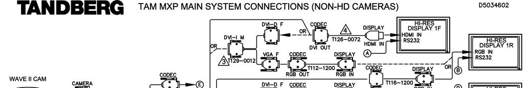
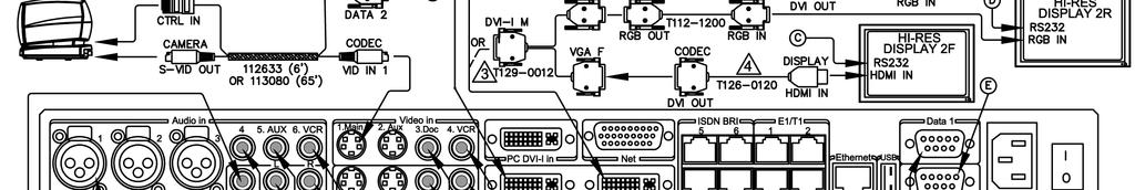
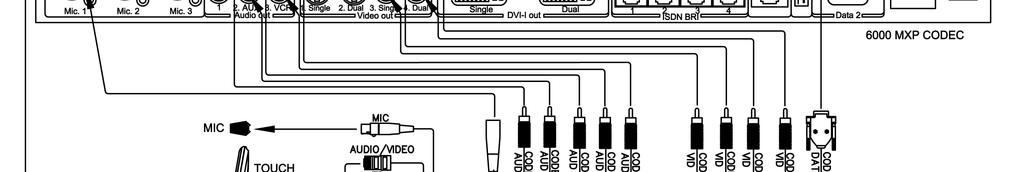
17 INSTALLATION & SETUP 2.1 System Connections The following schematic diagrams indicate how the system is to be connected. Refer to TAM MXP SYSTEM CONNECTIONS (D ) for the MAIN system connections using non-hd cameras. Refer to TAM MXP ANCILLARY SYSTEM CONNECTIONS (D ) for connecting the peripheral equipment used to enhance your videoconferencing experience. There is the option of connecting up to three TANDBERG Precision HD Cameras to this system (TAM MXP) using the TANDBERG Video Switch (TVS). The TVS enables the system to switch between the HD camera signals. Refer to the APPENDIX for connections diagram and installation notes: TAM MXP SYSTEM CONNECTIONS WITH HD CAMERAS (D ). D
18 INSTALLATION & SETUP D
19 INSTALLATION & SETUP D


20 INSTALLATION & SETUP 2.2 Powering Up the System When all connections have been made to the system, you may supply power and start-up the system. It is recommended that you power up the codec first and then the rest of the system. 1. Connect power to the included power strip and apply the following connections to the strip. 2. Connect AC power to the codec and power on. 3. Connect DC power to the TAM MXP the system will power-up automatically Once the system is powered-up, the touch panel will become active and run through a 15 second boot cycle. The system is ready when the Welcome Screen is displayed on the touch panel. NOTE: If there is no communication between the touch panel and the TAM MXP, then you will see a DIAGNOSTIC BOOT UP SCREEN and not proceed to the Welcome Screen. Follow the onscreen instructions to resolve problem. Please consult you support personnel or TANDBERG representative if you are unable to proceed beyond this page. NOTE: Before proceeding with your system, be sure to provide basic setup and configuration for the codec by following the procedures outlined in General Configuration and Network Configuration in 2.3 System Configuration. D
.")
21 INSTALLATION & SETUP 2.3 System Configuration The system must be configured for each installation. Network, audio, and other codec configuration settings are made using the TANDBERG Remote Control (see 3.1 Using the Remote Control). NOTE: While the touch panel is the primary source for presentation operation, the remote is required for codec setup and menu navigation. Video switching controlled by the remote control will not function properly. You must use the touch panel to control video switching. You may use either the physical remote control or the touch panel emulation of the remote control both function identically. 1. Press TOUCH TO START on the Welcome Page after the system has run through its boot cycle. 2. Press the OK button on the remote control to display the Main Menu on your main display monitor. (Be sure to point the remote in the direction of the WAVE camera as the IR sensor is located on the front of the camera.) 3. Navigate through the menu system using the arrow keys and OK. Press Cancel [ X ] to return to the previous Menu. NOTE: If an external IMUX or non-standard network is being used it may be necessary to configure any associated external equipment. NOTE: Refer the TANBDERG 6000 MXP User Manual for detailed codec menu navigation and configuration. General configuration: 1. Open the General Settings menu a. Press OK to open the Main Menu (if it is not already open). b. Select Control Panel and then select Administrator Settings. c. Select General to open the General Settings menu. 2. Language Press OK in the Language field and select the language you want to use from the list. There are 13 languages to choose from. D

22 INSTALLATION & SETUP NOTE: This changes the language used on the menus of the codec only and not the touch panel! 3. System Name Enter a name in the System Name field using the number keys on the remote control, as you would do with a mobile or cellular phone. 4. Dual Monitor If you are using two monitors, set Dual Monitor to On. If you are using one monitor, set Dual Monitor to Off. 5. Auto Answer, Max Call Length, Global Phone Book Settings and Permissions Leave Auto Answer, Max Call Length, Access code and Permissions unchanged if no special needs are required. 6. Screen Settings When using wide screen (16:9) monitors, set TV Monitor Format to Wide (16:9). TANDBERG also recommends setting Picture Layout to Picture outside Picture when using 16:9 monitors. Picture outside Picture provides a display layout optimized for wide screen monitors. The display layout may be changed at any time using the Layout button on the remote control. 7. Software Options To activate MultiSite and bandwidth, you must enter a new option key in the Software Options menu (see paperwork accompanying your system). For more information on these options, contact your TANDBERG representative. 8. Save changes Remember to save any changes you make in a menu by selecting the Save button on the Menu line and pressing OK. Network configuration: 1. Open the Network menu Open the Administrator Settings menu and choose Network. 2. ISDN configuration Set Current Network to the network you want to use. Specify the settings for the selected network in the relevant menu. D
23 INSTALLATION & SETUP 3. LAN configuration In the Administrator Settings menu, choose Network and LAN Settings. Specify the necessary LAN settings according to the instructions from your LAN administrator. 4. Save changes Remember to save any changes you make in a menu by selecting the Save button on the Menu line and pressing OK. Monitor volume: 1. Adjust monitor volume Use the monitor remote control to adjust the volume of the monitors. This volume will be the default volume for all calls. D
24 GENERAL USE 3.0 General Use Wake up the system When the system is not in use, the touch panel will be in standby mode and associated display screens will be black. Wake up the system by touching the touch panel screen to activate it. An incoming call will also wake up the system when appropriately configured in Utilities (see 4.4 Utilites). If the system does not respond: Verify that your monitor(s) is switched on. To switch the monitor on you normally push the power button on the front of the monitor (depending on monitor type). Make sure that the AC power is connected to the codec and is switched on by using the On/Off switch located at the rear of the codec Make sure that the DC power to the TAM MXP is connected. The following sections will describe the how to navigate the codec: 3.1 Using the Remote Control 3.2 Using the Menu D

25 GENERAL USE 3.1 Using the Remote Control The TANDBERG Remote Control is used to navigate the codec menus for setup and configuration. Think of the remote control as a mobile phone with number keys and call keys. Use the arrow keys and OK to navigate the menu. The system s most commonly used functions are also accessible directly from the remote control. The Infra Red (IR) sensor for the remote control is located in front of the WAVE II Camera. There is also a second IR-sensor located in the front of the Codec itself, which will be automatically enabled if the WAVE II Camera is not connected to Dataport 2. NOTE: While the touch panel is the primary source for presentation operation, the remote is required for codec setup and menu navigation. Video switching controlled by the remote control will not function properly. You must use the touch panel to control video switching. You may use either the physical remote control or the touch panel emulation of the remote control both function identically. You can access the remote emulator on the touch panel by entering the Utilities page and selecting System Setup > CODEC SETUP. D
26 GENERAL USE Remote Control Emulation Setup on Touch Panel There are a few settings on the Remote Control Emulation page that will aid in configuring which screens will be able to see the codec menus when it is accessed, both by the physical remote and the emulation remote controls. View Codec/Local With Picture in Picture (PIP), Layout makes it possible to see an extra picture in a smaller view. Codec on Screen Menus Enable on all outputs Selecting this option enables codec menus to be present on local displays. Active on touchpanel Selecting this option enables codec menus to be present ONLY on the display window of the Remote Control Emulation page. Press COMPLETE to save your settings. D

27 GENERAL USE Remote Control Operation 1. Mic Off turns your microphone on and off. 2. Arrow keys are used for navigation in the menu and for moving the camera when the menu is hidden. 3. Volume + and adjusts the system volume. 4. The Layout key toggles between full screen and different display layouts. 5. Cancel takes you back one step in the menu system. Use Cancel to delete characters in an input field. 6. Press the Call key to place a call. 7. Camera presets define specific camera positions. Press and hold a number key for 1 second to save the current camera position to that number key. To activate a preset whilst in a call, simply press and release that number key. 8. Snapshot takes a snapshot of your video. (Only while you are in a call) 9. The Presentation key switches to a predefined presentation source. 10. Press OK/Menu to show the menu and to select menu items. 11. Use Zoom + and to zoom the camera in and out. 12. Selfview displays your outgoing video. Press Selfview again to turn selfview off. 13. Store and recall your video contacts via the system Phone Book for easy placement of calls. 14. Use the red End Call key to end the current call. Pressing this key when not in a call will place the system in Standby mode. 15. Number/Letter keys function in the same manner as with a mobile or cellular phone. 16. Press Touch tones when you are in a call and need to dial extension numbers etc. (instead of presets) Navigation Arrow keys and OK Navigate in the menu with arrow keys. The yellow selector on screen shows the selected item. Press OK to select. Cancel key In the main menu, pressing Cancel (X) will hide the menu. If the menu is hidden, bring it back with OK. In other menus, pressing Cancel (X) takes you one step back. In an input field, pressing Cancel (X) will delete characters/numbers to the left. Back/Cancel button The X button in the menu corresponds with the X key on the remote. D

28 GENERAL USE Selfview Selfview shows your outgoing picture. Normally this is the picture of yourself (main camera). Selfview is most useful for single monitor systems. On dual monitor systems you already have selfview on the dual monitor. In a normal conference, the far end side is displayed on main monitor. Pressing Selfview will result in near end on main monitor. Outside a call, selfview is already displayed on the screens. Pressing selfview will display the TANDBERG logo on a black screen. Press selfview again to bring the picture back Layout Picture in Picture The Layout button has two behaviors depending on the Picture Layout setting in Administrator Settings. It can provide either a Picture in Picture or a Picture outside Picture. With Picture in Picture (PIP), Layout makes it possible to see an extra picture in a smaller view. Pressing Layout will bring up a picture in picture in the corner of the screen. Press Layout again to move it to the other corners of the screen and finally hide it. You can also hide it directly by pressing and holding Layout for 1 second. Picture in picture will always appear on the main monitor. Automatic PIP is the system's default setting. That means that you will automatically show Picture in Picture when it is suitable. How to use Layout for Picture in Picture: 1. Press Layout once to bring up a picture in picture. 2. Press Layout three more times to move it around in the corners of the screen. 3. The fourth time you press Layout, it will disappear. 4. Pressing and holding Layout for 1 second will hide the small picture directly from any position. Picture outside Picture With Picture outside Picture (POP), pressing Layout will bring up compositions of the pictures that are optimized for wide screens. Press once to get an extra picture in a smaller view. Press twice to get side-by-side view. Press again to go back to full screen view. You can also go back to full screen directly by pressing and holding Layout for 1 second. It is recommended to use Picture outside Picture for wide screen monitor systems. How to use Layout for Picture outside Picture: D
.")

29 GENERAL USE 1. Press Layout once to get the 1+3 layout. You see a big far end picture and a smaller picture of yourself in the upper right corner. If you use Duo Video, you see a big picture of the Duo Video and small pictures of the far end and yourself. 2. Press Layout again to get the side-by-side layout (1+1). You see two equally big images of the far end and yourself. 3. The third time you press Layout you go back to normal full screen view. 4. Pressing and holding Layout for 1 second will bring you back to full screen anytime. NOTE: If both TV monitor format and VGA format (in Administrator Settings\General\Screen Settings) are set to Normal, the system will skip the 1+3 layout, which is not beneficial for 4:3 monitors Mic Off To mute your microphone during a call, press Mic off. An on-screen indicator appears when the microphone is off. In a call, if audio is detected, the on-screen symbol will start to flash. Pressing Mic off one more time will activate the microphone again. Mic off will mute all microphone inputs and audio 4 input, but will not mute audio from the AUX and VCR inputs. Be aware that many calls are connected automatically with Mic off, because the Auto Answer settings are On+Mic off. The icon will start to flash when you start speaking. Remember to turn the microphone on before a meeting Volume [ + ] and [ - ] Press the Volume key to adjust the volume level. An on-screen indicator will show the current level. D

30 GENERAL USE Numbers and Letter Keys Pressing a number key when you are outside a call will take you to the call menu. When you are in a call, the number keys are used for Camera Presets. Press a number and you go to the corresponding Camera Preset. However, when you are in an input field where numbers are required, the system automatically goes to number mode and you can dial numbers with the number keys as usual. When you are in an input field where letters are required, the system automatically goes to letter mode. Writing letters works like on a mobile phone. Press the key that corresponds to your desired letter. Press the key as many times as you need to get the right letter. Change to lower or back to upper case letters with the a/a key, and space with the 0 _ key. To write numbers in a text input field, press the button through all the letters. Press once more and the number will appear. EXAMPLE: How do I write "System 123" in the System Name input field (in General in Administrator Settings)? Press the 7-key four times to get an "S". Press the #-key once to switch between upper case and lower case letters. Press the 9-key three times to get a "y". Press the 7-key four times to get an "s". Press the 8-key once to get a "t". Press the 3-key twice to get an "e". Press the 6-key once to get an "m". Press the 0-key once to get space. Press the 1-key three times to get a "1". Press the 2-key four times to get a "2". Press the 3-key four times to get a "3" Touch Tones Sometimes you need to dial extension numbers with the number keys when you are in a call. Pressing numbers will result in a camera preset. In these cases, press # to enable Touch tones. An indicator will tell that touch tones are enabled. Now you can enter your extension number with the number keys. Finish with OK to exit Touch tones mode. D
31 GENERAL USE On-Screen Indicators The system has a number of icons signalling different settings: Volume Off This indicator is shown when the volume is turned off. Press Volume + to turn the volume back on. Microphone Off This indicator is shown when the microphone is turned off. The indicator will start to flash if audio is detected in the room during a call and the microphone is turned off. Press the Mic off button again to turn the microphone back on. Secure Conference, AES This double padlock indicator is shown when AES encryption (Secure Conference) is active. Secure Conference, DES This Padlock indicator is shown when DES encryption (Secure Conference) is active. Not Secure Conference This open padlock indicator is shown during the initialization phase for encryption. During this period the call is not secure. Floor This indicator is shown when you are displayed in full screen in a multipoint conference. Participating Telephone This indicator is shown when there are 1 or more telephone participants in the conference. D

32 GENERAL USE 3.2 Using the Menu This TANDBERG system utilizes the codec s menu structure and ability to make calls, store presets, etc.-- all of the codec functions are available through the touch panel interface. This allows the user the ability to control codec functions as well as the other components connected to the TANDBERG system. When not using the touch panel, the menu is the interface you will use for your presentations. The main menu contains: Make a Call, Standby, Phone Book, Move Camera, Presentation, Multipoint Services and Control Panel. When you are in a call, Add Another Call and End Call will be available via the green and red buttons. The menu automatically times out after 15 seconds. Press OK/Menu to bring it back. You can also hide the menu manually by pressing Cancel (X) in the main menu. Please refer to the TANDBERG 6000 MXP User Manual for detailed information about the menu structure and menu item functionality. D


33 TOUCH PANEL OPERATION 4.0 Touch Panel Operation Upon start-up the interactive touch panel will display the INTRODUCTORY SPLASH PAGE. Information Press the button to display a basic information page: D

34 TOUCH PANEL OPERATION Your Support Personnel Your System Information Basic Diagnostics contact information for system support personnel. This information can be set by accessing the UTILITIES page. provides basic information about your system. informs whether the codec is connected and if the codec detects a video signal from the camera. Touch to Start Press to enter the MAIN CONFERENCE page where you will begin your presentations. Refer to section 4.1 Main Conference Page and following for presentation operation. Touch Panel Setup Pressing the grey button on the bezel of the touch panel affects only the touch panel and not the operation of the TANDBERG system. Press once to place the touch panel in standby mode. Press again to activate the screen, or simply touch the touch panel screen. Press and hold the button for approximately 5 seconds to display the touch panel setup page. NOTE: Changes to this will affect touch panel operation! D

35 TOUCH PANEL OPERATION 4.1 Main Conference Page The Main Conference Page is the launching pad from which you will begin your presentation. The following image describes what the user will initially see after start-up. Information & Status Provides information about the system: Time Indicators displays the current time as set by the user/administrator VCR Rec, Tel-Add, Streaming, and Call Connected indicators will illuminate when active Call Connection will illuminate green when the system is connected in a call Message Line will displays status and diagnostic information, as well as prompts when required. Video Display Window This window will display the currently selected video source. The Local Video (Main Cam) is the default video source. D
36 TOUCH PANEL OPERATION Controls Semi-transparent controls which are associated with the currently selected source are overlaid on the video window. These source controls can be configured to persist or fade after a few seconds. See System Setup for configuration options. Main Source Selection This area provides available sources to select from during presentation. The source names can be modified by the system administrator. Taskbar This area provides the necessary controls for presentation, as well as call control. Different functions will be available when applicable. Call Control Presentation Disconnect Layout Controls Far End Audio Home Utilities Access Make a Call When in a call, initiates or ends Presentation. Refer to the TANDBERG Codec User Manual for detailed information about Presentation. When in a call, pressing this button disconnects a call Shows the video display layout options for the LOCAL view. Pressing this button repeatedly will toggle through several layout options. Displays set of controls associated with currently selected source When in call, provides Far End Camera Control (FECC) Adjust audio level within room. Select up to increase and down to decrease volume. Press the audio button to toggle Mic Mute. A Custom Mute option may also be available if configured in Utilities > System Setup > AUDIO SETUP. Returns the user to the Main Page and resets the system to a known default state resets audio to a mid-range level and switches the video source to show the Main Camera source. The Utilities button provides access to secondary conference controls (i.e. standby settings, system tools, system setup, and Do-Not-Disturb mode.) D


37 TOUCH PANEL OPERATION 4.2 Making a Call Placing a videoconference call is a simple process: 1. Enter the Make A Call page 2. Manually dial a number or select a directory entry to dial. 3. Press Call Now to connect. Done. Of course, there are other functions and options that you will want to utilize to enhance your presentation or video call, but the basics of placing a call can be achieved in three steps. All of the calling is done from the CALL CONTROL page. The following sections will describe the touch panel pages and its functions. Press the green Call Control button at the lower-left of the touch panel main screen to enter the Call Control page. NOTE: If you have an EXTERNAL NETWORK configured, you will see an external network Call Control selection option as shown above-right. Otherwise, you will enter the main Call Control page as shown aboveleft. Video Window This window will display the currently selected video source: When not in a call = local video When in a call = remote site(s) Call Options These buttons provide call and directory options. See Call Control for more information. D
38 TOUCH PANEL OPERATION Call Utilities These options are available to provide support in a call: Tel. Add Touch Tones Streaming It is possible to connect a telephone (POTS) as part of the conference call. This is an option please consult your TANDBERG representative. When in a call, pressing this button brings up a touchpad for you to enter additional numbers, such as extension numbers, that require touch tones. See Touch Tones for more information, Activates and deactivates streaming. You can also activate streaming through UTILITIES > STREAM CONTROLS. Refer the TANDBERG 6000 MXP Manual for Streaming details. Taskbar This area provides the necessary controls for call control, as well as system utilities. Different functions will be available when applicable. Return Presentation Call Status Audio Home Utilities Returns to Main Page When in a call, initiates or ends Presentation mode When in a call, provides call status and options to add site, disconnect a particular site, or disconnect all sites. Adjust audio level within room. Select up to increase and down to decrease volume. Press the audio button to toggle mic mute. Returns the user to the Main Page and resets the system to a known default state resets audio to a mid-range level and switches the video source to show the Main Camera source. Provides access to secondary conference controls (i.e. standby settings, system tools, system setup, and Do-Not-Disturb mode.) D
.")
39 TOUCH PANEL OPERATION Call l Control The Call Control page is where you will select or enter a number to dial and begin your videoconference call. The default page will display either the LOCAL or GLOBAL DIRECTORY page (depending on which page was accessed last). The area with the green highlight will contain the calling options to place a call. D

40 TOUCH PANEL OPERATION Manual Dial If you are placing a call that is not in the directory, you may enter the number manually by pressing the MANUAL DIAL button on the Call Control page. 1. Enter the NUMBER or ADDRESS you wish to dial. You may enter any combination of alphanumeric* characters by pressing AB@C to use the pop-up keyboard. * TANDBERG s F2 codec software supports URI Dialing for dialing names, H.323 IDs, and addresses. 2. Press EDIT to modify any call options necessary: a. Call Type: select Video or Telephone b. Network: select ISDN, IP (H.323), or SIP c. Restrict: select On or Off for Restricted 56k networks d. Bandwidth: increase [ + ] or decrease [ - ] your call rate bandwidth 3. Press CALL NOW to place the call. The touch panel will return to the MAIN conference page when the call connects. You may place additional calls, manually or from the Directory, to begin a MultiSite session if that option is enabled (see MultiSite for MultiSite operation). If no call is placed, press the Directory button to return to the main Call Control page. Directory The Local directory is a local, user defined set of entries used for placing calls. The Corporate or Global directories are available from an external directory management application such as TMS (TANDBERG Management System). D
41 TOUCH PANEL OPERATION Pressing Directory repeatedly will toggle between the Local and Global or Corporate directories. See Utilities > System Setup > CALL SETUP to configure directory preferences. Local Dir Corporate Dir Contains the locally stored entries. These entries are only available on the individual system as entered by the system administrator or local user. The Corporate Directory is made available to your system through a management application such as the TANDBERG Management System (TMS). This allows your system to access the latest corporate directory information, which has been pushed out to your codec, on the fly without having to download an entire directory to the touch panel. No updating or downloading is required. This minimizes having to update the touch panel manually, whenever new global information is made available. Global Dir The Global Directory is also made available to your system through a management application such as the TANDBERG Management System (TMS). As TMS regularly update the codec with the latest global directory information, you will need to manually synchronize the codec and the touch panel. New Press the NEW button to setup a new local directory entry. 1. Press the? for Name. A keyboard will pop-up with which you will enter the directory entry name. The same applies for Number. 2. Configure the Call Type, Network, Restrict, and Bandwidth settings for the entry. 3. Press OK to save or CANCEL to return to the Directory page. Delete Selecting DELETE will allow you delete the currently selected directory entry. If a delete confirmation screen does not appear, ensure that the DELETE button is highlighted orange and then select the entry you wish to delete. Select OK-DELETE to confirm entry deletion or select CANCEL to the Directory page. Edit Selecting EDIT will allow you modify the currently selected directory entry. If an editable entry does not appear, ensure that the EDIT button is highlighted orange and then select the entry you wish to modify. Call Now Select CALL NOW while a directory entry is highlighted to place a call. A call will not be placed if an entry is not selected. D

42 TOUCH PANEL OPERATION History This button will display the last 7 numbers that have been MANUALLY DIALED. You will also see either right-pointing green arrows to indicate calls you have placed, and/or left-pointing blue arrows to indicate calls you have received. MultiSite This allows dialing of MultiSite conferences to be initiated by a single selection from the MultiSite directory presented on the page. A MultiSite call must be first configured within the codec using the IR remote then downloaded to the TAM MXP from the Call Setup page. D

43 TOUCH PANEL OPERATION 4.3 When In a Call When a call has been placed, you will return to the MAIN CONFERENCE page. Here you will see CAMERA CONTROLS and taskbar controls that will aid your presentation. You will now be able to: disconnect your call enhance your presentation with DuoVideo add additional sites for a MultiSite videoconference call (requires MultiSite option to be installed). Call Control Presentation Disconnect Layout Controls Far End Access call controls When in a call, initiates or ends a Presentation Session When in a call, disconnects a call Toggles through room video display layout options Display controls associated with currently selected source When in call, provides Far End Camera Control (FECC) D

44 TOUCH PANEL OPERATION Presentation tion Presentation can be a very effective presentation tool that enables you to present material other than just the main camera. You are now able to present contents of a connected PC/laptop computer, a document camera, or a video clip from a VCR or DVD player. 1. While in a videoconference call, press PRESENTATION. If the button is not present, you are not able to initiate a Presentation session at this time. 2. The Presentation page will appear. You will see source selections for the MAIN video display, as well as the source selections for the PRESENTATION display. 3. Select the desired PRESENTATION source you wish to present. The far-end site will be able to see your selected source. 4. Press PRESENTATION again to discontinue sending a presentation source. This will not disconnect your call. D

45 TOUCH PANEL OPERATION Far End Control It is possible to get some control of the far end system. This means that you can control your conference partner s camera, video sources and presets. Enabling Far End Control in the codec s Control Panel will put the system in Far End mode and camera control, camera preset, presentation, and snapshot will work on the far end camera. See Far End Control in the TANDBERG 6000 MXP Manual for more details. You can initiate Far End Control using your touch panel only if the Far End has been properly configured. Press the FAR END button to enter the Far End Control page. If the Far End is not configured to do, the touch panel will display Far End Control Not Possible. (You may ask the Far End participant to enable Far End Control via their codec s Control Panel.) Far End Sources Video Windows Presets on Far End Far End Camera Control (FECC) Taskbar Lists the available Far End sources to access and control. Displays the Far End (remote) view as the predominant view and the Near End (local) video in a smaller view. Far End Camera Presets works just like your own camera presets. When Far End is on, use the number keys to activate far end camera presets. You are however not allowed to save far end camera presets. Provides control over the Far End camera. Press NEAR END to release Far End Control and return to local control. The Far End Control TASKBAR contains AUDIO and HOME buttons as on the other pages. D
. The participants are tiled up on the screen and are on display simultaneously in a Split Screen.")
46 TOUCH PANEL OPERATION MultiSite The optional MultiSite capability enables several sites to participate in the same conference. You can have a maximum of 6 video- and 5 telephone-participants including yourself (the host). The participants are tiled up on the screen and are on display simultaneously in a Split Screen. During an MCU conference, the status line will provide information about the conference. You can connect a MultiSite conference in different ways. The MultiSite Services vary depending on how you make the call. Refer to the TANDBERG 6000 MXP User Manual for more about MultiSite and MCU Services. 1. While in a call, press CALL CONTROL and select a directory entry or enter a number manually. 2. Press CALL NOW to connect. Notice that, unlike a single call, the touch panel will remain on the CALL CONTROL page and not move to the MAIN CONFERENCE page. Repeat steps 1 and 2 if you would like to connect additional sites. You can add a site at any time by entering the CALL CONTROL page. 3. Press RETURN to return to the MAIN conference page. 4. Press MULTISITE to enter the MultiSite control page. D
.")
47 TOUCH PANEL OPERATION Transmit Site This area lists the participants that are currently in your conference. If you are the HOST SITE, you may press the TRANSMIT SITE button and select a participating site to be viewed by all participants ( Assign Floor ). Pressing TRANSMIT SITE again will return the floor to the setting defined by MultiSite Options below. MultiSite Options Options for conference participation and MultiSite video window layout options (see TANDBERG 6000 MXP Manual for more on MultiSite). Request/Release Floor When requesting floor, your video will be broadcasted in full screen to all other participants in the conference. Request Floor is useful when you want to speak or display something in front of all participants. Therefore, floor will automatically be requested when taking a Snapshot or Selecting Document Camera or PC. Release Floor when you are done and make the floor available for other participants in the conference. An indicator appears when you have floor and disappears when you release floor. Layout With a TANDBERG MultiSite you can choose between the layouts: Auto Split displays all participants on the screen simultaneously 4 Split displays the 4 last speaking Participants 5+1 Split displays the speaking participant in a big picture and the other participants in small pictures Voice Switched displays the participant that is speaking in full screen Local View Layout Taskbar Provides LOCAL video window layout options. Layout This button will toggle though the layout options. You may also select the layout you want by pressing one of the appropriate quick-select layout buttons just to the left. The layout options will differ according to your Picture-in-Picture or Picture-outside-Picture settings. Selfview Press to display Selfview (your local video). This selection will show you the video that you are sending to the remote sites. When in MultiSite, the Taskbar area will display the AUDIO and HOME options as on the other pages. It will also allow you to return to the MAIN PAGE by pressing the Main Page button. 5. Press MAIN PAGE to return to the MAIN conference page as you need to add or disconnect sites. D

48 TOUCH PANEL OPERATION Disconnecting a Call Pressing the red DISCONNECT button during a call will prompt you to confirm the termination of that call before the connection is terminated. When in a MultiSite call, pressing the DISCONNECT button will allow you to choose to disconnect individual sites, or to disconnect the entire MultiSite session. DISCONNECT SITE will bring up the Disconnect Status page where you can individually select a site or sites to disconnect. EXIT will return you to the Call Status page. DISCONNECT ALL will terminate all connections. Pressing and holding the DISCONNECT button will also terminate all currently active calls. D

49 TOUCH PANEL OPERATION 4.4 Utilities There are a number of setup options and configurations that can be utilized to customize and configure your system. Press the UTILITIES button to enter the utilities and setup page. Standby/Log-off System Information System Setup Secondary Communications Room Tools Configuration Return Logs off and places the System in standby mode. You will be returned to the start page. Provides basic system information Allows for further setup and configuration options. See System Setup. STREAM CONTROLS and TELEPHONE ADD-ON behave the same way as the Call Utility functions -- press to activate or deactivate. Press to enable/disable configured PRESSURE MATS and ROOM CONTROLS (i.e. lights, projectors, audio, etc.). These options are configured in System Setup > ROOM SETUP. DO NOT DISTURB: press to activate Do Not Disturb. While this is active, you will NOT accept (autoanswer) any incoming calls. AUTO ANSWER: press to activate (green) Auto Answer. When not activated, you must manually accept any incoming calls. You may also configure Auto Answer with the Mic on or off when it connects. Returns to the MAIN conference page. D

50 TOUCH PANEL OPERATION System Setup Further configuration options are available from this page. Pressing RETURN will return you to the MAIN conference page. D

51 TOUCH PANEL OPERATION Audio/Video Sources The audio and video sources configurable to your system are listed on this Equipment Setup page: Source Screen Name Device/Model Source Configuration Custom Setting The SOURCE column lists all available sources for configuration. The names associated with the icons are the physical connection names. You can rename the displayed names for these sources in Screen Name below. Sources not active are greyed-out, but can be made active by selecting one and marking it ACTIVE in Source Configuration below. The SCREEN NAME column informs what label is given to the source that will be displayed on touch panel. The screen name can be modified by selecting the associated source to be modified and pressing RENAME SOURCE in Source Configuration below. The DEVICE/MODEL column informs what device or model is configured for each source. This can be modified by selecting the associated source to be modified and pressing CHANGE MODEL TYPE under Custom Settings. Each available source is configurable as needed. Modifies the selected source Active/Activate, Change Icon, Rename Source Change Model Type, Change Mode. The appropriate options will appear depending on which source is connected and selected for customization. EXAMPLE: I want to connect a Sony EVI-D100 as a second camera to my system. How do I configure the second camera? D
52 TOUCH PANEL OPERATION 1. Ensure proper connection of the second camera to the TAM control and video, and supply power to the camera as well. It is recommended that you connect your device before you proceed with configuration. If the camera is not connected before you configure it to the system, you will have to repeat much of the following procedure for verification, as well as make sure that you identify the specific camera you have connected. 2. Navigate from the main conference page to the AUDIO/VIDEO SOURCES page: Utilities > System Setup > AUDIO/VIDEO SOURCES 3. Select CAMERA #2 under Source. When you select a source, the Source Configuration and Custom Settings areas will appear with the appropriate options. 4. In the Source Configuration area, press Activate to enable Camera #2. The button will change to ACTIVE. 5. In the Source Configuration area, you can press Change Icon to select a different icon that will be associated with Camera #2. The selected icon is what will be displayed on your touch panel. 6. In the Source Configuration area, press the Rename Source button if you wish to associate a specific name to Camera #2. A keyboard will appear for you to type in the desired name. Press DONE on the keyboard to accept the given name. 7. In the Custom Settings area, you will see the Change Model Type button. Press this button repeatedly to toggle though the set of identifiable devices until you see your specific device -- SONY EVI-D100. If you did not connect the second camera before configuration, you will not see the specific device in Change Model Type. You must return to the AUDIO/VIDEO SOURCES page, select Camera #2, and select the specific camera in Change Model Type. 8. Press COMPLETE when you are finished with configuration, or repeat the procedure if you wish configure another device. D

53 TOUCH PANEL OPERATION Display Equipment The DISPLAY & SCREEN SETUP page allows you to manage display configurations and options according to the connections you have made for your system: Predefined configurations are made available for setting up the system. In the event a custom configuration is necessary, pressing the CUSTOM CONFIGURATION button will take you the DISPLAY & SCREEN ADVANCE SETUP page. D
 or Normal (4:3) and select display resolution XGA(1024x768, SVGA (800x600), or Auto.")
54 TOUCH PANEL OPERATION Monitors Picture in or Out of Picture Monitor Format Room Display Type Select First Displays Video Mode Second Displays Video Mode select single or dual monitor setup select PIP or POP as default video window layout options select Wide (16:9) or Normal (4:3) and select display resolution XGA(1024x768, SVGA (800x600), or Auto. Set the type of display associated with the First and Second display connections -- Net TV, Plasma, etc. As noted on the touch panel, the display references the physical connection on the rear interface panel. select Hi-Res/DVI or Composite Video displays select Hi-Res/DVI or Composite Video displays D

55 TOUCH PANEL OPERATION Room Setup Pressure Mats Selecting PRESSURE MATS allows the user to setup the Pressure Mat operation and presets associated with a particular mat. Up to 5 pressure mats can be configured. Which camera s presets controlled is selected by the button beneath the move camera message. It is important to note that the pressure mat number equates to the camera preset +1, so activating pressure mat one will call camera preset 2. Camera preset one is always the Room Shot but this preset is a configurable step off option. A test indicator of which mat is active is built into the pressure mat setup and will flash the Mat Box Input number. The name displayed in the Video Switch selection is the number programmed for the source button. D

56 TOUCH PANEL OPERATION Room Control Selecting ROOM CONTROL allows the user to configure and assign different room control parameters. Selecting Stream System Data to remote controller can add additional room control functionality via another control system. Use Port will identify for you which port is available to connect to the external control system. D

57 TOUCH PANEL OPERATION Camera Presets Selecting CAMERA PRESETS allows the user to configure existing presets, as well as configure additional camera presets. All the presets for the Main, Second and Auxiliary 1 camera can be seen, renamed, or deleted from this page. Select either the delete or rename camera preset function. Select the camera source. Select the camera preset, an active preset is indicated by the blue button border. If you choose to rename a preset a keyboard will be seen with the current name displayed. You will also be asked to confirm deletion of a preset. Selecting the More buttons will show the next 20 presets. Press and Hold the delete button to clear all of the selected cameras presets. The ROOM SHOT cannot be renamed. D

58 TOUCH PANEL OPERATION Touch N Talk Configuration This presents your options to configure the Touch N Talk microphones to switch to the MAIN, SECOND, or AUXILIARY camera (if the Aux Cam is enabled). After selecting the Touch N Talk configuration button the first 20 microphone button are seen, the other 20 can be accessed by selecting the MORE buttons. Selecting a microphone button will display a RED MESSAGE BOX in which the camera source and its preset can be configured. Use the UP and DOWN arrow keys to scroll through the camera 40 preset the preset name is shown in the text window. Select OK to confirm the configuration. RESTORE DEFAULTS will reset all the Touch N Talk microphones to switch to the main camera and the camera preset 1 over the microphone number. IE, microphone 1 will call main camera preset 2. An ACTIVE TOUCH N TALK indicator is also provided above the restore default button. D

59 TOUCH PANEL OPERATION Audio A Setup Telephone Add Stereo I/O Mode Speakers Custom Mute Press to enable or disable TEL-ADD. You must have a TANDBERG Tel Add unit in order to utilize this function. Please consult your TANDBERG representative. NOTE: If Tel-Add is active, then Stereo I/O Mode is disabled automatically. Enable if not Tel-Add is present it is recommended that Stereo I/O Mode be set as default selection. This transmits stereo audio from the VCR and Auxiliary sources, and receive stereo audio to the VCR (recording). NOTE: You cannot have Stereo I/O Mode active if you have Tel-Add active. Select to enable TANDBERG satellite speakers connected to the D-NAM. Disable if no satellite speakers are connected. Custom Mute allows the user to configure any combination of the following mic/audio inputs in order to create one mute option for those selected inputs: Mic In #1, Mic In #2, Mic In #3, and Audio In #4. The custom mute button will appear when the user selects the volume control buttons or the mic mute button. Select to activate a customized mute option. Activating the Custom button will prompt you to input a label for the custom mute button modify as needed. Then select which mic/audio input to mute when EXAMPLE: A videoconferencing classroom has three microphones. One microphone is intended for the instructor (Mic In #1), while the other two microphones (Mic In #2, #3) are designated for the classroom. If the classroom environment is generally noisy, the instructor may have configured the custom D

60 TOUCH PANEL OPERATION mute option as shown above in the Audio Setup page Mic In #2, #3 selected to mute. The instructor can then press the volume control button to show the custom mute button and select it. This will mute the classoom mics while keeping the instructor s mic active, helping to eliminate any extraneous noise Call C Setup The Call Control Setup page is available to set up default call settings, enable or disable streaming from the touch panel, and setup how the touch panel will manage your calling directories: Default Call Allow Streaming Local Directory MultiSite Directory Press to set the default Manual Dial profile. Press to display the ability to initiate Streaming on the call/conference pages. Contains directory entries for the local system only. Any new or edited entries via the touch panel are stored locally in the touch panel and codec it is not available to the other systems. You may need to periodically update your touch panel (local directory) with any new directory information that may be pushed to the codec by a management such as the TANDBERG Management System (TMS). Updating the local directory may take some time depending on the amount of data the system needs to upload. This feature allows dialing of MultiSite conference to be initiated by a single selection from the new MultiSite directory. A MultiSite directory entries must be first configured within the codec using the IR remote, then downloaded to the TAM MXP from the Call Setup page. D

61 TOUCH PANEL OPERATION Global/Corporate Directory Select to activate the directory you select Global or Corporate. If this is not activated, you will only see local directory information. Choose to display either a Corporate or Global directory when in the Call Control page: Global/Corporate Directory CORPORATE GLOBAL The Corporate Directory is made available to your system through a management application such as the TANDBERG Management System (TMS). This allows your system to access the latest corporate directory information, which has been pushed out to your codec, on the fly without having to download an entire directory to the touch panel. No updating or downloading is required. This minimizes having to update the touch panel manually, whenever new global information is made available. The Global Directory is also made available to your system through a management application such as the TANDBERG Management System (TMS). As TMS regularly update the codec with the latest global directory information, you will need to manually synchronize the codec and the touch panel. Select Download Global Directory to synchronize Access Setup The Access Control Setup page allows for the setup and configuration of user ID and PASSWORD verification from the opening page. Set password protection for System Setup and/or Access Setup. D

62 TOUCH PANEL OPERATION Support S Information System Information Your Support Personnel Calibrate Touchpanel edit your SYSTEM NAME. Provides basic system information. These details can also be viewed on the Information Page from the Startup Page. enter/modify the support contact information. These details can also be viewed on the Information Page from the Startup Page. Press and follow the on-screen instructions to calibrate the touch panel User Interface Operation You have three options for how you can interact with the touch panel and its controls. The default configuration is where you will see persistent and semi-transparent source controls and preset panels. This configuration is referred to as the Classic Educator style. The second option, when selected, will fade source controls. Additionally: Camera controls always are available on the touch panel video display. Pan and tilt controls appear as small, directional arrows on the edges of the video window. Zoom controls appear as [+] and [-] in the corners of the right-side of the video display. Preset buttons have no background Presets 2-6 can be positioned on the touch panel video window to quickly identify which location the preset will call. D


63 TOUCH PANEL OPERATION The third option allows a main screen interface to be created that would meet your aesthetic requirements. UI Style Your Interface The design of Your Interface must follow the guidelines explained in the TANDBERG Document D50431x.PDF available from the FTP.TANDBERGUSA.COM/public/solutions web site. The touch panel comes with 24 generic pages that can be redesigned using AMX TPDesign 4 software. These pages provide the basic video/audio switching and device control functionality required to operate the system. This screen (generic Main Page ) provides access to the 11 video inputs along with layout, presentation and audio controls. A small video window (shown here as the black square) shows the currently selected source. Access to the Dialing & Conference Tools pages is also available. As a source is selected its associated controls are displayed (seen here in the light colored box). Your Interface may not require all the source or functionality provided it which case the buttons can be removed and the pop-up pages not used. This feature is enabled after the touch panel design file has been updated by the integrator; at which point, to enable this feature, select User Interface Setup Your Interface. The Your User Interface Setup page will be displayed. Select Enable Your Interface; if the integrator has redesigned the source control pop-up pages, select the Use Your Source Controls button. D
.")

64 TOUCH PANEL OPERATION Opening Page Logo This feature allows the opening page logo to be changed to show a custom logo. This feature requires that the touchpanel and control system communicate over ethernet (not the default ICSNet). The custom logo is uploaded to the control system s FTP server which the touchpanel then downloads this image. Configure this feature within the System Setup >> User Interface >> Opening Page Logo Select the Your Logo button and verify the Comms message box reads Ethernet. Enter the user name and password if required. Selecting the Refresh will download the image from the FTP and display its thumbnail. The image can be either a JPG or PNG format and no larger than 650 pixel width X 400 pixel height. The file must be named logo.jpg. To upload the file: 1. Log into your local control system FTP server in this example it is ftp:// You will be prompted for a user name and password, the default (unless changed): User Name: administrator Password: password 3. When successfully logged on create a new directory called STARTUP, select File New. 4. Copy the desired logo.jpg into the STARTUP directory. 5. The new logo will be displayed after the TAM MXP is restarted or a refresh is made by pressing and holding the center of the opening page. D

65 TOUCH PANEL OPERATION Codec Setup This page will emulate the handheld TANDBERG Remote Control that is used to setup and configure the codec. Press the appropriate buttons on the touch screen remote to navigate the codec menu structure and settings. See 3.1 Using the Remote Control System IP Setup This page is used to setup and establish the Network Connection for your TANDBERG system. Select each setting to configure using the options that toggle through, or the keypad that appears Time You may configure the date and time on the touch panel. Press the TIME box next to the text System Setup and make adjustments accordingly. D
66 SERVICING 5.0 Appendix 5.1 Integrating TANDBERG Precision HD Cameras with the TANDBERG Video Switch Up to three HD Cameras -- TANDBERG Precision or Sony EVI-HD2 -- can be integrated into this system (TAM MXP), using the TANDBERG Video Switch (TVS), to provide high-definition video. The TVS enables the system to switch between the HD camera signals. These cameras correspond to Camera 1, Camera 2 and the Auxiliary 1 camera. Depending on the type of the camera it will either connect to the DVI-D or RGB input. The camera type is automatically detected by the TAM MXP, this in turn controls which TVS input is selected when the user selects Camera 1, 2 or Aux 1 on the touch panel. NOTE: Do not use the documentation provided with the switch. The documentation included with the switch is for installation with a codec only, and will not address proper integration with this system. HD CAMERA ADAPTER PLATE Switching out / mounting the HD cameras will require the installation of an adapter plate that will integrate with the existing camera shelf. a. Secure the HD Camera to the Adapter Plate. b. Then make appropriate camera connections with the cables coming through the cable egress from the existing camera mount. Use cable T134 (HDMI/female) at camera when using TANDBERG Plasma Cart. c. Secure the Adapter Plate to the exiting camera mount. D

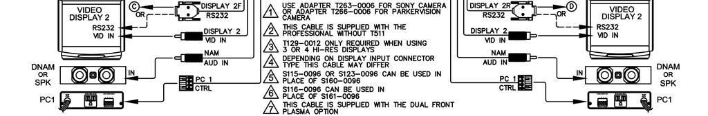
67 SERVICING CAMERA OPTIONS SOURCE INPUT CAMERA DETECTED USES TVS INPUT CONTROL CONNECTION CABLE Camera #1 Precision HD DVI-D #1 Via TVS Data 1 HD (6 ) C6000 Camera #2 Precision HD DVI-D #2 Direct via Display 2 breakout Use adapter T Sony EVI HD1 RGB #5 Direct via Display 2 breakout Use adapter T Auxiliary #1 Precision HD DVI-D #3 Direct via Aux 1 control T277 cable spec Sony EVI HD1 RGB #6 Direct via Aux 1 control T212 cable spec Camera #1 Ctrl To Codec Dataport 2 Camera #1 Auxiliary #1, DVI 3 or RGB 6 Camera #2, DVI 2 or RGB 5 DVI Cabling: The DVI connections to the TVS are Digital only (DVI-D) Power: Each camera and the TVS will require a 12VDC power supply. TRC4 Remote Control: This remote can be used but the direct video input switch buttons will not function correctly with the TAM MXP. TANDBERG recommends rack mounting the TVS within 6 (1.5m) of the codec. If you have the TANDBERG student cart, there is 1U blank panel above the codec, or on the 2U shelf. The power distribution bars behind the PC connection should have adequate outlets available. The TVS OUTPUT connects to the codec digital input on DATAPORT #2 replacing the existing Precision camera which now connects to CAMERA 1. CAMERA 1 (student) connects to DVI-D 1 and control to DATA 1 HD CAMERA 2 (instructor) connects to DVI-D 2 if you are using a Precision HD or RGB 5 if you using a Sony EVI HD1. Be sure to use the appropriate control adaptor on the WAVE II Control In connector (see table above). AUXILIARY 1 connects to DVI-D 3 if you are using a Precision HD or RGB 6 if you using a Sony EVI HD1. DISTANCE CONSIDERATIONS If using the Precision HD camera as an instructor camera (looking at one specific person), it should be no further than 30 (9m) from the subject due to the zoom capabilities of the camera. Using the Sony EVI HD1 the camera can placed up to 50 (15m) away from the subject and the RGB cabling required can be run up to 100 (30m). D
68 SERVICING AUXILIARY 1 CABLING Auxiliary 1 port on the rear of the TAM MXP contains both an RS232 and IR port -- the RS232 part is used for camera control, and the IR part for VCR/DVD control. Which one is used depends on what is configured within the Audio/Video Source setup. Auxiliary 1 to Sony Camera Cable (TANDBERG Drawing: T212A) Auxiliary 1 to TANDBERG Precision HD Camera Cable (TANDBERG Drawing: T277A) CONNECTION DIAGRAM WITH TANDBERG VIDEO SWITCH The schematic on the following page will show how the TVS is to be integrated with the TANDBERG Precision HD cameras. Please note that the connections are different from the non-hd connection diagram (D ). D

69 SERVICING D


70 AUDIO IN VIDEO IN CONTROL AUX 1 / CCM R L AUX 2 AUX 3 PC AUD IN L/R SWITCH/ANNO. VCR / DOC TOUCHPANEL 1ST DISPLAYS 2ND DISPLAYS DISPLAYS AUDIO IN This device complies with part 15, subpart B, class A of the FCC Rules. O peration is subject to the fol lowing two conditions: (1) Thi s device m ay not cause harmful interference, and (2) This device m ust accept a ny interference received, including interference that m ay cause undesired operation. CODEC I/O P. M ATS RS232 CONTROL TNT IN TEL-ADD IN OUT MODEL: TAM-3 12VDC 4A max. A SSEMB LE D in USA S/N: ICSNet C R US T P PROGRAM ETHERNET CS 12 VDC IN TANDBERG Educator & Professional MXP Videoconferencing System SERVICING 5.2 NXT-1200V Touchpanel Setup (Part#: ) TAM MXP installations not connected to LAN This installation will require a CAT5 crossover cable be connected between the CS (control system) and the TP (touchpanel) connections on the rear of the TAM MXP. A crossover cable installation will require the installer to configure a static IP Address on both the controller and touchpanel. This will require you to connect to the TAM MXP Program port at 38400, N, 8, 1 using a null-modem cable. When connected issue the command SET IP then follow the instructions. The following settings are set as DEFAULT: Controller IP: (static) Subnet: Gateway: TAM MXP CAT5 crossover cable (T ) With no communications the touchpanel will display a page that allows the installer to configure the Touchpanel IP and TAM MXP IP settings. Configure Touchpanel Connection with the information in the following table. TP ETHERNET CS Touchpanel IP Connection to TAM MXP DHCP/Static Static Type Ethernet IP Mode URL Subnet System Number 0 (unchanged) PRESS HERE Gateway Master IP Master Port 1319 (unchanged) TAM MXP installations connected to LAN If the TAM MXP CS (control system) is already connected to the LAN then the crossover cable option is not applicable. A CAT5 LAN cable is required from the LAN to the TP connection on the TAM MXP. With no communications the touchpanel will display a page that allows the installer to configure the Touchpanel IP and TAM MXP IP settings. Configure the Touchpanel Connection similarly to the above table in accordance to the network information supplied by the local IT department. Continue system setup with the instructions found in the Educator & Professional MXP Manual. Touchpanel Software Two different versions of software now exist for the TAM MXP touchpanel. NXT-1200V will be appended by (1200V) for example TAM MXP, V7_00_0 (1200V).TP4 NXT-CV12 will continue to use the standard format TAM MXP, V7_00_0.TP4 Both software version designs are exactly the same in D
User Manual. Software version F2 D This document is not to be reproduced in whole or in part without permission in writing from:
 User Manual Software version F2 D13356.03 This document is not to be reproduced in whole or in part without permission in writing from: 1 D1335603_T770_880_990_MXP_User_Manual Trademarks and Copyright
HD Digital Set-Top Box Quick Start Guide
 HD Digital Set-Top Box Quick Start Guide Eagle Communications HD Digital Set-Top Box Important Safety Instructions WARNING TO REDUCE THE RISK OF FIRE OR ELECTRIC SHOCK, DO NOT EXPOSE THIS PRODUCT TO RAIN
Evolution Digital HD Set-Top Box Important Safety Instructions
 Evolution Digital HD Set-Top Box Important Safety Instructions 1. Read these instructions. 2. Keep these instructions. 3. Heed all warnings. 4. Follow all instructions. 5. Do not use this apparatus near
Tandberg 1700 MXP User Guide
 Tandberg 1700 MXP User Guide Rev 08Sept2017 TABLE OF CONTENTS 1.0 OBJECTIVES... 3 2.0 THE TANBERG 1700 MXP... 3 3.0 GENERAL SET UP AND USE... 5 3.1 General Set Up... 5 3.2 Mute/Microphone... 6 3.3 Placing
Basic Use guidelines. TANDBERG 880 MXP System
 Basic Use guidelines TANDBERG 880 MXP System 1 Installing TANDBERG 880MXP Comes in 1 box Videoconferencing System with built-in Camera Power supply Table Microphone Remote Control with Batteries User manual
CAUTION RISK OF ELECTRIC SHOCK NO NOT OPEN
 Evolution Digital HD Set-Top Box Important Safety Instructions 1. Read these instructions. 2. Keep these instructions. 3. Heed all warnings. 4. Follow all instructions. 5. Do not use this apparatus near
2.0 Wall Mount TV Soundbar Instruction Manual
 8010275 2.0 Wall Mount TV Soundbar Instruction Manual Read all of the instructions before using this soundbar and keep the manual in a safe place for future reference. Safety Information CA UT IO N RISK
Installation Manual VIP 1003
 Installation Manual VIP 1003 We Caring for the Environment by Recycling When you see this symbol on a Motorola product, do not dispose of the product with residential or commercial waste. Recycling your
INSTALLATION MANUAL VIP 1903 / VIP 1903 T VIP 1963 / VIP 1963 T
 INSTALLATION MANUAL VIP 1903 / VIP 1903 T VIP 1963 / VIP 1963 T We Declaration of Conformity Motorola Mobility, Inc. 101 Tournament Drive Horsham Pennsylvania 19044 USA declare under our sole responsibility
User Manual. Software version E2. D This document is not to be reproduced in whole or in part without permission in writing from:
 User Manual Software version E2 D13099-02 This document is not to be reproduced in whole or in part without permission in writing from: 1 LCD MONITORS: Panel sticking and after-image lag Avoid displaying
User Manual. Software version E3/B8. D This document is not to be reproduced in whole or in part without permission in writing from:
 User Manual Software version E3/B8 D12155-10 This document is not to be reproduced in whole or in part without permission in writing from: 1 2 Trademarks and copyright COPYRIGHT 2004, TANDBERG Philip Pedersensvei
HD Digital MPEG2 Encoder / QAM Modulator
 HD Digital MPEG2 Encoder / QAM Modulator YPrPb VGA In QAM Out series Get Going Guide ZvPro 600 Series is a one or two-channel Component or VGA-to-QAM MPEG 2 Encoder/ Modulator, all in a compact package
Wireless 4 Channel Receiver with 2 Night Vision cameras
 Wireless 4 Channel Receiver with 2 Night Vision cameras Instruction Manual English Version 2.0 MODEL: SHS-4WLS www.lorexcctv.com Copyright 2006 LOREX Technology Inc. Thank you for purchasing the SHS-4WLS.
HD Digital MPEG2 Encoder / QAM Modulator
 HD Digital MPEG2 Encoder / QAM Modulator HDMI In QAM Out series Get Going Guide ZvPro 800 Series is a one or two-channel unencrypted HDMI-to-QAM MPEG 2 Encoder / QAM Modulator, all in a compact package
Getting Started Guide for the V Series
 product pic here Getting Started Guide for the V Series Version 9.0.6 March 2010 Edition 3725-24476-003/A Trademark Information POLYCOM, the Polycom Triangles logo and the names and marks associated with
HD Digital MPEG2 Encoder / QAM Modulator Get Going Guide
 series HD Digital MPEG2 Encoder / QAM Modulator Get Going Guide HDb2640 HDb2620 HDb2540 HDb2520 The HDbridge 2000 Series is a combination HD MPEG 2 Encoder and frequency-agile QAM Modulator, all in a 1RU
Wired to Wireless Camera Converter
 Wired to Wireless Camera Converter Instruction Manual English Version 1.0 MODEL: WL401BNC www.lorexcctv.com Copyright (c) 2006 LOREX Technology Inc. Thank you for purchasing the 2.4 GHz Wireless Camera
TS2.8 Sub OWNER S MANUAL
 TS2.8 Sub OWNER S MANUAL TS2.8 Sub CONTENTS IMPORTANT SAFETY INSTRUCTIONS 03 WARNINGS 03 FUSE PROTECTION 04 WARNING: STRONG MAGNETIC FIELD 04 EMC / EMI 04 ECODESIGN STANDBY POWER CONSUMPTION 04 WARRANTY
LED TV MODEL NO.: NE22K5BG. Please read this manual carefully before installing and operating the TV. Keep this manual handy for further reference
 LED TV USER MANUAL MODEL NO.: NE22K5BG IMPORTANT Please read this manual carefully before installing and operating the TV. Keep this manual handy for further reference Table Of Contents Preparations Guide
User Manual. Software version F4 D March This document is not to be reproduced in whole or in part without permission in writing from:
 User Manual Software version F4 D13722.04 March 2006 This document is not to be reproduced in whole or in part without permission in writing from: TANDBERG 1000 MXP Trademarks and Copyright All rights
AUTO - SCANNING WITH DIGITAL CONTROL LCD COLOR MONITOR FS-L1903C. User manual (Rev.01) SMITHS HEIMANN
 SMITHS HEIMANN") AUTO - SCANNING WITH DIGITAL CONTROL LCD COLOR MONITOR FS-L1903C User manual (Rev.01) SMITHS HEIMANN www.smithsdetection.com Table of Contents Safety Instructions... 5 Accessories... 8 Power Connections...
AUTO - SCANNING WITH DIGITAL CONTROL LCD COLOR MONITOR FS-L1903C User manual (Rev.01) SMITHS HEIMANN www.smithsdetection.com Table of Contents Safety Instructions... 5 Accessories... 8 Power Connections...
Introduction. Important Safety Instructions
 Introduction Congratulations on purchasing your Eviant Portable Digital TV. On June 12, 2009 the conversion to digital television broadcasting will be complete all throughout the United States and Puerto
Disclaimer. Warning and Caution CAUTION!
 Disclaimer While every effort has been made to ensure that the information contained in this guide is accurate and complete, no liability can be accepted for any errors or omissions NUVICO reserves the
SX80 with Touchpad 10 User Guide
 SX80 with Touchpad 10 User Guide Rev 11May2017 Page 1 of 19 Table of Contents OVERVIEW.... 3 BASIC NAVIGATION.... 4 GENERAL USE.... 5 Setup... 5 Camera Controls... 6 Microphone.... 8 Volume.... 9 Site
Getting Started Guide for the V Series
 product pic here Getting Started Guide for the V Series Version 8.7 July 2007 Edition 3725-24476-002/A Trademark Information Polycom and the Polycom logo design are registered trademarks of Polycom, Inc.,
 Register your product and get support at www.philips.com/welcome SWS3435S/27 SWS3435H/37 EN User manual Contents 1 Important 4 Safety 4 English 2 Your SWS3435 6 Overview 6 3 Installation 7 Connect the
2.4 GHz WIRELESS VIDEO SENDER SYSTEM MODEL: VS6234
 2.4 GHz WIRELESS VIDEO SENDER SYSTEM MODEL: VS6234 Please read this manual thoroughly before operating this system OPERATING INSTRUCTIONS 03/02 1 SAFETY INSTRUCTIONS CAUTION! RISK OF ELECTRIC SHOCK. DO
VSX Series Getting Started Guide
 VSX Series Getting Started Guide September, 2003 Edition 3725-21286-002/A VSX SERIES GETTING STARTED GUIDE Trademark Information Patent Information Polycom and the Polycom logo design are registered trademarks
ZVOX AccuVoice TV Speaker Model AV203
 ZVOX AccuVoice TV Speaker Model AV203 SETUP & OPERATION www.zvoxaudio.com READ THIS FIRST Important Safety Instructions For ZVOX Audio System WARNING TO PREVENT FIRE OR SHOCK HAZARD, DO NOT EXPOSE THIS
SX10/20 with Touchpad 10
 SX10/20 with Touchpad 10 rev 24Sept2018 Page 1 of 19 Table of Contents Table of Contents OVERVIEW.... 3 BASIC NAVIGATION.... 4 GENERAL USE.... 5 Setup... 5 Camera Controls... 6 Microphone.... 8 Volume....
SX Series with TRC6 Remote Control User Guide
 SX Series with TRC6 Remote Control User Guide Rev 11May2017 Page 1 of 19 OVERVIEW.... 3 BASIC NAVIGATION.... 4 GENERAL USE.... 5 Setup... 5 Microphone.... 6 Volume.... 6 Site to Site Calls.... 7 Connecting
28 4K LED monitor. User Manual M284K
 28 4K LED monitor User Manual M284K CONTENTS Safety Information... 2 What s included..... 4 Getting Started....... 8 Troubleshooting.... 14 Specification.... 15 2 of 15 SAFETY INFORMATION Read these instructions
Quick Reference TV guide. Getting Started. with Cogeco Digital TV.
 Quick Reference TV guide Getting Started with Cogeco Digital TV. Welcome to Cogeco Digital TV At Cogeco, we put you first in everything we do. Our goal is to give you a TV experience unlike any other from
DM-1CH SD DVB-T MODULATOR INSTRUCTION MANUAL
 DM-1CH SD DVB-T MODULATOR INSTRUCTION MANUAL 2. Caution Statements and Table of Contents Table of Contents 2. Caution Statements and Table of contents 3. Important Safety Instructions 4. Important Safety
May 2006 Edition /A. Getting Started Guide for the VSX Series Version 8.5
 May 2006 Edition 3725-21286-008/A Getting Started Guide for the VSX Series Version 8.5 GETTING STARTED GUIDE FOR THE VSX SERIES Trademark Information Polycom, the Polycom logo design, and ViewStation are
HDMI 5x1 Switch B-240-HDSWTCH-5X1 INSTALLATION MANUAL
 HDMI 5x1 Switch B-240-HDSWTCH-5X1 INSTALLATION MANUAL IMPORTANT SAFETY INSTRUCTIONS To reduce the risk of fire or electric shock, read and follow all instructions and warnings in this manual. Keep this
ZVOX AccuVoice TV Speaker Model AV203
 ZVOX AccuVoice TV Speaker Model AV203 SETUP & OPERATION www.zvoxaudio.com 2 ZVOX AccuVoice TV Speaker Setup & Operation READ THIS FIRST Important Safety Instructions For ZVOX Audio System WARNING TO PREVENT
Check our knowledge base at
 USER MANUAL Check our knowledge base at www.paralinx.net/support Copyright 2015 Paralinx LLC All Rights Reserved TABLE OF CONTENTS 1 Important Notice 10 LCD Screen 2 Safety Instructions 11 Indicators 3
Camera 220C Document Camera User s Guide
 Camera 220C Document Camera User s Guide #401-220C-00 Table of Contents TABLE OF CONTENTS... 0 TABLE OF CONTENTS... 1 COPYRIGHT INFORMATION... 2 CHAPTER 1 PRECAUTIONS... 3 CHAPTER 2 PACKAGE CONTENT...
February 2007 Edition /A. Getting Started Guide for the VSX Series Version 8.5.3
 February 2007 Edition 3725-21286-009/A Getting Started Guide for the VSX Series Version 8.5.3 GETTING STARTED GUIDE FOR THE VSX SERIES Trademark Information Polycom, the Polycom logo design, and ViewStation
User Manual. Software version F5 D June This document is not to be reproduced in whole or in part without permission in writing from:
 User Manual Software version F5 D13721.05 June 2006 This document is not to be reproduced in whole or in part without permission in writing from: TANDBERG 550 MXP Trademarks and Copyright All rights reserved.
4 PORT HDMI SWITCH
 4 PORT HDMI SWITCH 1518896 IMPORTANT SAFEGUARDS OF HDMI SWITCH PRODUCTS PLEASE READ CAREFULLY THE FOLLOWING SAFEGUARDS THAT ARE APPLICABLE TO YOUR EQUIPMENT 1. Read instructions - All the safety and operating
Operating Instructions
 Operating Instructions SDI Input board Model No. AV-HS04M1 РУССКИЙ FRANÇAIS DEUTSCH ENGLISH ESPAÑOL ITALIANO Before operating this product, please read the instructions carefully and save this manual for
ATTACHING & REMOVING THE BASE
 TV53DB ATTACHING & REMOVING THE BASE 1. To install or remove the neck, screw in or remove the 4 screws indicated in the picture. 2. To install the base, place the display unit flat on a table. Afterwards
Service FOR SERVICE. Quick Reference Guide. Page 23. Contact your help desk at
 Service Page 2 FOR SERVICE Contact your help desk at Quick Reference Guide 0 Judson Street, Unit 5 Toronto, ON M8Z 5T6 Tel: -800-652-266 www.adcom.ca Copyright 2004 Power Source Page 22 UPS Connect the
Color Video Monitor. Instruction Manual. Read this manual thoroughly before use, and retain it for maintenance.
 Color Video Monitor Instruction Manual Read this manual thoroughly before use, and retain it for maintenance. The product s exterior design and specifications may subject to change without prior notice
CP-255ID Multi-Format to DVI Scaler
 CP-255ID Multi-Format to DVI Scaler Operation Manual DISCLAIMERS The information in this manual has been carefully checked and is believed to be accurate. Cypress Technology assumes no responsibility
Monochrome Video Monitors
 Instructions for Use Monochrome Video Monitors En F D E NL I LTC 2009 LTC 2012 LTC 2017 Philips Communication & Security Systems GB F D E NL I Instructions for Use...1.1 Mode d emploi...2.1 Bedienungsanleitung...3.1
Tandberg 880 MXP User Guide
 Tandberg 880 MXP User Guide Rev 13Sept2017 Table of Contents 1.0 OBJECTIVES...3 2.0 THE TANDBERG 880 MXP...3 NAVIGATION BUTTONS...6 3.0 GENERAL SETUP AND USE...7 3.1 General Setup...7 3.2 Mute/Microphone...7
English. User Manual sub8 Subwoofer SUBWOOFER. Supporting your digital lifestyle
 English User Manual sub8 Subwoofer U SUBWOOFER Supporting your digital lifestyle Table of Contents Important Safety Precautions........ 2 Introduction / What s in the Box?...... 3 Front & Rear Panels............
 Register your product and get support at www.philips.com/welcome SWW1890 User manual Contents 1 Important 4 Safety 4 English 2 Your Philips Wireless HD Net Connect 5 What is in the box 5 3 Overview 6
December 2006 Edition /A. Getting Started Guide for the VSX Series Version 8.6 for SCCP
 December 2006 Edition 3725-24333-001/A Getting Started Guide for the VSX Series Version 8.6 for SCCP GETTING STARTED GUIDE FOR THE VSX SERIES Trademark Information Polycom and the Polycom logo design are
55" Curved Ultra HD LED TV User s Guide for Model TU5587B v For the most up-to-date version of this User s Guide, go to
 55" Curved Ultra HD LED TV User s Guide for Model TU5587B v1922-01 For the most up-to-date version of this User s Guide, go to www.gpx.com Safety Instructions & Warnings CAUTION RISK OF ELECTRIC SHOCK
TANDBERG EDUCATOR 2. Installation & Configuration Manual. Software Version B4 Control Software V4.1
 TANDBERG EDUCATOR 2 Installation & Configuration Manual Software Version B4 Control Software V4.1 D50103-06 This document is not to be reproduced in whole or in part without the permission in writing from:
SAFETY INFORMATION. 7. Do not force switched or external connections in any way. They should all connect easily, without needing to be forced.
 SAFETY INFORMATION 1. To ensure the best results from this product, please read this manual and all other documentation before operating your equipment. Retain all documentation for future reference. 2.
HDBaseT RECEIVER B-520-RX-230-IR INSTALLATION MANUAL
 HDBaseT RECEIVER B-520-RX-230-IR INSTALLATION MANUAL IMPORTANT SAFETY INSTRUCTIONS To reduce the risk of fire or electric shock, read and follow all instructions and warnings in this manual. Keep this
Winmate Communication INC.
 20.1 Military Grade Display Model: R20L100-RKA2ML User s Manual Winmate Communication INC. May, 2011 1 IMPORTANT SAFETY INSTRUCTIONS Please read these instructions carefully before using the product and
FD Trinitron Colour Television
 R 4-205-569-32(1) FD Trinitron Television Instruction Manual GB KV-14LM1U 2000 by Sony Corporation NOTICE FOR CUSTOMERS IN THE UNITED KINGDOM A moulded plug complying with BS1363 is fitted to this equipment
Register your product and get support at SDV5122/27. EN User manual
 Register your product and get support at www.philips.com/welcome SDV5122/27 User manual Contents 1 Important 4 Safety 4 Notice for USA 5 Notice for Canada 5 Recycling 6 English 2 Your SDV5122 7 Overview
Utility Amplifier GA6A Model
 Utility Amplifier GA6A Model Installation and Use Manual 2004 Bogen Communications, Inc. All rights reserved. Specifications subject to change without notice. 54-5757-03D 1503 NOTICE: Every effort was
HDBaseT RECEIVER B-540-RX-330-IR INSTALLATION MANUAL
 HDBaseT RECEIVER B-540-RX-330-IR INSTALLATION MANUAL IMPORTANT SAFETY INSTRUCTIONS To reduce the risk of fire or electric shock, read and follow all instructions and warnings in this manual. Keep this
DC162 Digital Visualizer. User Manual. English - 1
 DC162 Digital Visualizer User Manual English - 1 Table of Contents CHAPTER 1 PRECAUTIONS... 5 CHAPTER 2 PACKAGE CONTENT... 7 CHAPTER 3 PRODUCT OVERVIEW... 8 3.1 PRODUCT INTRODUCTION... 8 3.2 I/O CONNECTION...
OWNER'S MANUAL MODEL: DTV-2000 STANDBY/ON
 OWNER'S MANUAL MODEL: DTV-2000 STANDBY/ON CH+ CH- TABLE OF CONTENTS SAFETY PRECAUTIONS IMPORTANT SAFETY INSTRUCTIONS and FEATURES ACCESSORIES and LOADING BATTERIES REMOTE CONTROL UNIT FRONT PANEL and REAR
2.4 GHz WIRELESS VIDEO SECURITY SYSTEM
 2.4 GHz WIRELESS VIDEO SECURITY SYSTEM Please read this manual thoroughly before operating this system OPERATING INSTRUCTIONS Rev 03/01-1 SPECIFICATIONS WIRELESS CAMERA Image sensor Lens Picture element
KD-CSW2x1. Operating Instructions. 2 Inputs to 1 Output Component Video/Audio Switcher. KD-CSW2x1 Operating Instructions.
 KD-CSW2x1 2 Inputs to 1 Output Video/ Switcher Operating Instructions Key Digital, led by digital video pioneer Mike Tsinberg, develops and manufactures high quality, cutting-edge technology solutions
User Manual. AtlonA. 1 x 10 VGA with Stereo Audio Distribution Amplifier over CAT5/6 compatible with AT-VGA300RL AT-VGA10SS
 User Manual AtlonA 1 x 10 VGA with Stereo Audio Distribution Amplifier over CAT5/6 compatible with AT-VGA300RL AT-VGA10SS TABLE OF CONTENTS 1. Introduction... 3 2. Package Contents... 3 3. Features...
Be sure to run the vehicle engine while using this unit to avoid battery exhaustion.
 CAUTION: TO REDUCE THE RISK OF ELECTRIC SHOCK DO NOT REMOVE COVER (OR BACK) NO USER-SERVICEABLE PARTS INSIDE REFER SERVICING TO QUALIFIED SERVICE PERSONNE; Please Read all of these instructions regarding
USER MANUAL MX102 & MX1202
 USER MANUAL MX102 & MX1202 WWW.PULSE-AUDIO.CO.UK 1 SAVE THESE SAFETY INSTRUCTIONS Thank you for purchasing our product. To assure the optimum performance, please read this manual carefully and keep it
Date of Test: 20th 24th October 2015
 APPENDIX 15/03 TEST RESULTS FOR AVER EVC130P Manufacturer: Model: AVer EVC130p Software Version: 00.01.08.62 Optional Features and Modifications: None Date of Test: 20th 24th October 2015 HD Camera CODEC
HD-1603 Single Input MPEG-4 DVB-T HD Encoder/Modulator User Guide and Install Manual
 ZyCastR digi-mod HD Range digi-mod HD-1603 www.digi-modbyzycast.com HD-1603 Single Input MPEG-4 DVB-T HD Encoder/Modulator User Guide and Install Manual Table of Contents www.digi-modbyzycast.com Safety
 Register your product and get support at www.philips.com/welcome SWW1810 User manual 3 Contents 1 Important 4 Safety 4 English 2 Your Wireless HD AV Connect 6 What is in the box 6 3 Overview 7 The transmitter
SW 50. Powered Subwoofer with Built-in Stereo Crossover
 Owner s Manual SW 50 ed Subwoofer with Built-in Stereo Crossover Congratulations on your new purchase and welcome to the AudioSource family of satisfied customers. We trust you will continue to enjoy the
HDBaseT RECEIVER B-520-RX-330-IR INSTALLATION MANUAL
 HDBaseT RECEIVER B-520-RX-330- INSTALLATION MANUAL IMPORTANT SAFETY INSTRUCTIONS To reduce the risk of fire or electric shock, read and follow all instructions and warnings in this manual. Keep this manual
1 x 10 Component Video with Stereo and Digital Audio Distribution Amplifier over CAT5/6 compatible with AT-COMP300RL AT-COMP10SS
 1 x 10 Component Video with Stereo and Digital Audio Distribution Amplifier over CAT5/6 compatible with AT-COMP300RL AT-COMP10SS User Manual www.atlona.com TABLE OF CONTENTS 1. Introduction 2 2. Features
OWNER S MANUAL EVOLUTION SERIES POWERED SUBWOOFER ES-SUB-EVO6-100
 OWNER S MANUAL EVOLUTION SERIES POWERED SUBWOOFER ES-SUB-EVO6-100 Important Safety Instructions CAUTION RISK OF ELECTRIC SHOCK! DO NOT OPEN! ATTENTION! RISQUE DE CHOC! ÉLECTRIQUE PAS OUVRIR! The lightning
1812R Blues King 12. User Manual
 1812R Blues King 12 User Manual All contents c Absara Audio LLC 2018 1. Important Safety Information The triangle surrounding an exclamation mark alerts users to the presence of important warnings or information.
Z-IP Stream 004/008. User Guide and Installation Manual. Four or Eight Input QAM Encoder / Modulator
 Z-IP Stream 004/008 User Guide and Installation Manual Four or Eight Input QAM Encoder / Modulator MPEG-2 / H.264 HD ENCODER with QAM /IP/ & ASI Outputs Contents Safety Precautions... 3 Package Contents...
Cisco MX200/MX300/EX90 User Guide
 Cisco MX200/MX300/EX90 User Guide Prepared by: MBTelehealth Rev 13Sept2017 Table of Contents 1.0 OVERVIEW... 3 2.0 GENERAL USE... 5 2.1 How to Use the Touch Screen... 5 2.2 Set Up and Use of Videoconference
CFT2200. User Guide 0(18 6(/(&7 (17(5 92/80( &+$11(/ ( 6 6 $ * ( 6
 CFT2200 User Guide 0 ( 6 6 $ * ( 6 0(18 6(/(&7 (17(5 92/80( &+$11(/ &$87,21 5,6.Ã2)Ã(/(&75,&Ã6+2&. &$87,21 75('8&(Ã7+(Ã5,6.Ã2)Ã(/(&75,&Ã6+2&. '127Ã5(029(Ã&29(5Ã25Ã%$&. 186(56(59,&($%/(Ã3$576Ã,16,'( 5()(5Ã6(59,&,1*Ã748$/,),('Ã6(59,&(Ã3(56211(/
Q-TV2. User Manual. for Screens
 Q-TV2 User Manual for 30-42 Screens Contents Introduction 02 Safety Guidelines 03 Getting started 03 Potential Uses 04 Carton Contents 05 Q-TV2 Controls 05 Remote Fixings 06 Fixing Rails 07 Fitting Q-TV2
ZVOX AccuVoice TV Speaker MODEL AV150.
 ZVOX AccuVoice TV Speaker MODEL AV150 www.zvoxaudio.com READ THIS FIRST Important Safety Instructions For ZVOX Audio System WARNING TO PREVENT FIRE OR SHOCK HAZARD, DO NOT EXPOSE THIS APPLIANCE TO RAIN
COLOR DIGITAL WIRELESS SURVEILLANCE SYSTEM & INDOOR/OUTDOOR COLOR CAMERA(S) WITH AUDIO
 WITH AUDIO") COLOR DIGITAL WIRELESS SURVEILLANCE SYSTEM & INDOOR/OUTDOOR COLOR CAMERA(S) WITH AUDIO Instruction Manual English Version 1.1 MODELS: LW2100 Series www.lorexcctv.com Copyright 2008 Lorex Technology Inc.
COLOR DIGITAL WIRELESS SURVEILLANCE SYSTEM & INDOOR/OUTDOOR COLOR CAMERA(S) WITH AUDIO Instruction Manual English Version 1.1 MODELS: LW2100 Series www.lorexcctv.com Copyright 2008 Lorex Technology Inc.
Standard Digital Terminal High-Definition Digital Terminal. User Guide
 Standard Digital Terminal High-Definition Digital Terminal User Guide ILL-GDA-STD-001-0709 IN THIS GUIDE IMPORTANT RULES FOR SAFE OPERATION... 4 AVAILABLE ILLICO TERMINALS... 5 REMOTE CONTROLS... 17 CONNECTIONS...
HOME GUARD USER MANUAL
 HOME GUARD USER MANUAL CONTENTS 1. SAFETY PRECAUTIONS...2 2. INTRODUCTION...3 3. FEATURES...4 4. ACCESSORIES...5 5. INSTALLATION...6 6. NAME and FUNCTION of EACH PART...7 6.1 Front Pannel...7 6.2 Monitoring
CR10 REMOTE CONTROL SYSTEM
 CR10 REMOTE CONTROL SYSTEM CR10 REMOTE CONTROL SYSTEM IMPORTANT SAFETY INSTRUCTIONS THESE INSTRUCTIONS ARE TO PROTECT YOU AND THE MclNTOSH INSTRUMENT. BE SURE TO FAMILIARIZE YOURSELF WITH THEM 1. Read
Model#: IN-MDRI3MF. Hardware User Manual. 3MP Indoor Mini Dome with Basic WDR, Fixed lens. (PoE) Ver. 2013/02/04
 Ver. 2013/02/04") Model#: IN-MDRI3MF 3MP Indoor Mini Dome with Basic WDR, Fixed lens Hardware User Manual (PoE) Ver. 2013/02/04 Table of Contents 0. Precautions 3 1. Introduction 4 Package Contents... 4 Features and Benefits...
Model#: IN-MDRI3MF 3MP Indoor Mini Dome with Basic WDR, Fixed lens Hardware User Manual (PoE) Ver. 2013/02/04 Table of Contents 0. Precautions 3 1. Introduction 4 Package Contents... 4 Features and Benefits...
Congratulations on purchasing your Eviant Portable Digital TV.
 Introduction Congratulations on purchasing your Eviant Portable Digital TV. On June 12, 2009 the conversion to digital television broadcasting will be complete all throughout the United States and Puerto
Applications & Features of the SB- SDQM- 2130
 Applications & Features of the SB- SDQM- 2130 Retrofit Existing 12 in 1 Analog Head Ends Into Standard Definition QAM Analog to Digital in one easy step Allows insertion of operators scrambled programming
User Manual. Software version M2 D This document is not to be reproduced in whole or in part without permission in writing from:
 User Manual Software version M2 D13742.03 This document is not to be reproduced in whole or in part without permission in writing from: D1374203_User_Manual_MXP_CCM Trademarks and Copyright All rights
~ Instruction Manual ~
 ~ DJ-5 Professional Preamp mixer ~ 0 0 0 0 10 10 10 10 EVE MASTE GAIN GAIN 0 10 CUE EVE CH 1 CH 2 CUE PAN INE INE POWE FADE STAT FADE STAT HEADPHONES ~ Instruction Manual ~ ~ Important Safety Instructions
17 19 PROFESSIONAL LCD COLOUR MONITOR ART
 17 19 PROFESSIONAL LCD COLOUR MONITOR ART. 41657-41659 Via Don Arrigoni, 5 24020 Rovetta S. Lorenzo (Bergamo) http://www.comelit.eu e-mail:export.department@comelit.it WARNING: TO REDUCE THE RISK OF FIRE
VF-STB IP Appliance User Guide
 VF-STB IP Appliance User Guide Copyright 2007 Video Furnace, Inc. All Rights Reserved. Copyright 2002-2007 Video Furnace, Inc. All Rights Reserved This document refers to the current published version
User Manual High Definition Digital Set Top Box DVBT9070 Please read this User Manual carefully to ensure proper use of this product and keep this man
 User Manual High Definition Digital Set Top Box DVBT9070 Please read this User Manual carefully to ensure proper use of this product and keep this manual for future reference. Important Safety Instructions
Acer LCD TV AT2001 User's Guide
 Acer LCD TV AT2001 User's Guide Copyright 2005. Acer Incorporated. All Rights Reserved. Acer AT2001 User' s Guide Original Issue: May 2005 Acer and the Acer logo are registered trademarks of Acer Incorporated.
E246 Series User Guide
 E246 Series User Guide PACKAGE CONTENTS SCEPTRE Display x 1 Display Base x 1 Display Neck x 1 Screws x 6 (ST3 x 10mm) Warranty Card x 1 Power Cord x 1 (Attached) Display Remote Control (AAA Batteries included)
Model 1421 Distribution Amplifier
 Model 1421 Distribution Amplifier Installation and Operating Instructions The 1421 Distribution Amplifier provides four independent, wide bandwidth outputs from one video input. The unit is color compatible
SKYPLAY-MX Installation and Operation Guide
 SKYPLAY-MX Installation and Operation Guide Rev 130412 Important Safety Instructions Please completely read and verify you understand all instructions in this manual before operating this equipment. Keep
Disclaimer. Trademarks. Copyright. Contact Us Control4 Corporation S. Election Road Salt Lake City, UT USA
 Disclaimer Trademarks Copyright Control4 makes no representations or warranties with respect to this publication, and specifically disclaims any express or implied warranties of merchantability or fitness
LINK-MI LM-WHD05B. Wireless HDMI AV Transmission System. User Manual
 LINK-MI LM-WHD05B Wireless HDMI AV Transmission System User Manual Table of Contents 1.Important Information... 3 1.1 Safety Precautions... 3 1.2 Declaration of Conformity... 4 1.3 Trademark Information...
Quick Reference Guide
 Multimedia Projector Quick Reference Guide MODEL 103-011100-01 Projection lens is optional. English Use this book as a reference guide when setting up the projector. For detailed information about installation,