Radio Test report
|
|
|
- Carol McKenzie
- 6 years ago
- Views:
Transcription

1 Radio Test report based on: Radio Equipment Regulations for Japan 82. abg compact flash module Summit Data Communications SDC-CFG
2 Report number: Contents MIN MODULE...3 INTRODUCTION PRODUCT TEST SCHEDULE PRODUCT DOCUMENTTION OBSERVTIONS ND COMMENTS SUMMRY CONCLUSIONS...6 TEST RESULTS MODULE...7 SUMMRY OF TESTS 82. W52 & W53 BNDS SUMMRY OF TESTS 82.B SUMMRY OF TESTS 82.G GENERL INFORMTION Equipment information Frequency test channels Test conditions ssembly ntenna specifications Radiation patterns TEST RESULTS 82. W52 & W53 BNDS Frequency Tolerance Occupied Bandwidth (99 % channel power bandwidth) Spurious emissions transmitter Out-band emission power djacent channel power tolerance ntenna Power Spurious emissions receiver Burst Length Carrier sense capability TEST RESULTS 82.B Frequency Tolerance Occupied Bandwidth (99 % channel power bandwidth) Occupied Bandwidth (9 % channel power bandwidth) Spurious emissions transmitter ntenna Power ngular width of principal radiation (WPR) Spurious emissions receiver TEST RESULTS 82.G Frequency Tolerance Occupied Bandwidth (99 % channel power bandwidth) Occupied Bandwidth (9 % channel power bandwidth) Spurious emissions transmitter ntenna Power ngular width of principal radiation (WPR) Spurious emissions receiver...52 USED TEST EQUIPMENT MODULE...54 PHOTOGRPHS MODULE...55 This report comprises of four modules. The total number of pages is: 64
3 Page: 3 of 3 Main module Report number: Main module Introduction This report contains the result of tests performed by: Telefication B.V. Edisonstraat 2a 692 PK Zevenaar The Netherlands Telefication complies with the accreditation criteria for test laboratories as laid down in ISO/IEC 725:25. The accreditation covers the quality system of the laboratory as well as the specific activities described in the authorized annex bearing the accreditation number L2 and is granted on 3 November 99 by the Dutch Council For ccreditation (Rv: Raad voor ccreditatie). The contents of this test report, if reproduced, shall be copied in full, unless special consent in writing for reproduction in part is granted by Telefication. Copyright of this test report is reserved to Telefication. Ordering party: Company name : Elliott Labs, Inc. ddress : 684 West Maude venue Zip code : City/town : Sunnyvale Country : United States of merica Date of order : 5 pril 28
4 Page: 4 of 4 Main module Report number: Product sample of the following product was submitted for testing: Product name : 82. abg compact flash module Manufacturer : Gemtek Technology Co., Ltd. Trade mark : Summit Data Communications Type designation : SDC-CFG Identification no. : -- Hardware version : V4 Software release : -- Serial number : CFG Test schedule Tests are carried out in accordance with the specification detailed in chapter 6 "Summary" of this report. Tests are carried out at the following location: Telefication; Zevenaar The sample of the product was received on: 4 June 28 Tests are carried out between: 3 June and July 28 4 Product documentation For production of this report the following product documentation has been used: Description: Date: Identification: Summit Manufacturing Utility Guide 2/3/8 Summit Data Communications, Inc. Electrical diagram, sht. 2 of 6, rev.4 6 Dec. 27 Dwg no. WCFB-8G_V2_S2 Electrical diagram, sht. 5 of 6, rev.4 6 Dec. 27 Dwg no. WCFB-8G_V2_S4 Block diagram Not dated WCFB-8G Operational description Not dated SDC-CFG Summit operating instructions Not dated -- The above-mentioned documentation will be filed at Telefication for a period of years following the issue of this report.
5 Page: 5 of 5 Main module Report number: Observations and comments For the purpose of testing a PD, type ipq, served as a host. ll measurements are carried out as conducted tests on the antenna connector. 6 Summary The product is intended for use in the following application area: Wireless Local rea Network (WLN) The sample is tested according to the following specification: Radio Equipment Regulations for Japan

6 Page: 6 of 6 Main module Report number: Conclusions The sample of the product showed NO NON-COMPLINCES to the specification stated in chapter 6 of this report. The results of the tests as stated in this report, are exclusively applicable to the product items as identified in this report. Telefication accepts no responsibility for any stated properties of product items in this test report, which are not supported by the tests as specified in chapter 6 Summary. ll tests are performed by: name function : ing. P.. Suringa : Senior Engineer Radio/EMC signature : Review of test methods and report by: name function : ing. K.. Roes : Senior Engineer signature : The above conclusions have been verified by the following signatory: date : 8 ugust 28 name function : J.P. van de Poll : Co-ordinator Test Group signature :
7 Page: 7 of 7 Test results module Summary of tests 82.a W52 & W53 bands rticle Report Status Requirement reference reference (note ) General provisions 5 5. Frequency tolerance C Occupied bandwidth C Spurious emissions C Transmitting equipment ntenna power tolerance C Transmitting antenna Type, configuration, etc. of transmitting antenna C Directional pattern of transmitting antenna C Receiving equipment Spurious emission of receiver C , 4.6 Refer to all articles for transmitting antenna C Operating frequencies 58, 52, 522, 524, 526, 528, 53 & 532 MHz 49.2 (3) (a) 4.4 High Frequency/modulation section cannot be opened C easily 49.2 (3) (b) 4. Communication method C 49.2 (3) (c) 4. Modulation method C 49.2 (3) (d) 4. Signal transmission rate C 49.2 (3) (e) 5.8 Burst Length C 49.2 (3) (f) 5.6 ntenna power tolerance C 49.2 (3) (g) 5.6 Isotropically radiated power C 49.2 (3) (h) 5.2 Number of carriers within MHz bandwidth in OFDM C 49.2 (3) (i) -- Spreading factor N 5.4 Out-band emission power C 49.2 (3) (j) 5.5 djacent channel power tolerance C MIC notice Carrier sense capability C Note : C = Conform NC = Not Conform NT = Not Tested N = Not pplicable
8 Page: 8 of 8 2 Summary of tests 82.b rticle Report Status Parameter reference reference (note ) General provisions 5 6. Frequency tolerance C Occupied bandwidth C Spurious emissions C Transmitting equipment ntenna power C SR N 5 6. Frequency stabilization C Transmitting antenna Type, configuration, etc. of transmitting antenna C Directional pattern of transmitting antenna C Receiving equipment Spurious emission of receiver C , 4.6 Refer to all articles for transmitting antenna C Operating frequency MHz 49.2(); a 4.4 High Frequency/modulation section cannot be opened C easily 49.2(); b 4. Communication method C 49.2(); c 4. Modulation method C 49.2(); d 4. Spread spectrum method C 49.2(); e 6.5 ntenna power C 49.2();f() 4.5 bsolute gain of transmitting antenna C 49.2();f(2) 6.6 ngular width of principal radiation (WPR) C 49.2(); g -- Number of carriers within MHz bandwidth in OFDM N 49.2(); h 6.3 Diffusion bandwidth C 49.2(); i 6.3 Spreading factor C 49.2(); j -- Frequency retention time (FH employed) N Operating frequency MHz 49.2(2); a 4. High Frequency/modulation section cannot be opened C easily 49.2(2); b 4. Communication method C 49.2(2); c 4. Spread Spectrum method C 49.2(2); d 6.5 ntenna power C 49.2(2); e 4.5 bsolute gain of transmitting antenna C 49.2(2); f 6.3 Diffusion bandwidth C 49.2(2); g 6.3 Spreading factor C 49.2(2); h -- Interference immunity function N Note : C = Conform NC = Not Conform NT = Not Tested N = Not pplicable
9 Page: 9 of 9 3 Summary of tests 82.g rticle Report reference reference Parameter General provisions 5 7. Frequency tolerance C Occupied bandwidth C Spurious emissions C Transmitting equipment ntenna power C SR N 5 7. Frequency stabilization C Transmitting antenna Type, configuration, etc. of transmitting antenna C Directional pattern of transmitting antenna C Receiving equipment Spurious emission of receiver C & 3.5 Refer to all articles for transmitting antenna C Operating frequency MHz 49.2(); a 4.4 High Frequency/modulation section cannot be opened easily C 49.2(); b 4. Communication method C 49.2(); c 4. Modulation method C 49.2(); d 4. Spread spectrum method C 49.2(); e 7.5 ntenna power C 49.2();f() 3.4 & 3.5 bsolute gain of transmitting antenna C 49.2();f(2) 7.6 ngular width of principal radiation (WPR) C 49.2(); g 7.2 Number of carriers within MHz bandwidth in OFDM C 49.2(); h 7.3 Diffusion bandwidth C 49.2(); i 7.3 Spreading factor C 49.2(); j -- Frequency retention time (FH employed) N Operating frequency MHz 49.2(2); a -- High Frequency/modulation section cannot be opened easily N 49.2(2); b -- Communication method N 49.2(2); c -- Spread Spectrum method N 49.2(2); d -- ntenna power N 49.2(2); e -- bsolute gain of transmitting antenna N 49.2(2); f -- Diffusion bandwidth N 49.2(2); g -- Spreading factor N 49.2(2); h -- Interference immunity function N Note : C = Conform NC = Not Conform NT = Not Tested N = Not pplicable Status (note )
10 Page: of 4 General information 4. Equipment information Equipment type designation SDC-CFG Type of equipment Data transmission equipment operating in the 2.4 & 5 GHz bands using spread spectrum techniques Modulation 82.a: Orthogonal Frequency Division (OFDM) 82.b: CCK 82.g: Orthogonal Frequency Division (OFDM) Operating frequency ranges MHz (W52 & W53 bands); MHz Rated conducted RF power IEEE 82.a.5 mw/mhz Rated conducted RF power IEEE 82.b 2.5 mw/mhz Rated conducted RF power IEEE 82.g 2.5 mw/mhz Signal transmission rate (max.) 82.a: 54 Mbps; 82.b: Mbps; 82.g: 54 Mbps 4.2 Frequency test channels 82.a W52 & W53 bands TX RX Channel MHz 58 MHz Channel MHz 524 MHz Channel MHz 526 MHz Channel MHz 532 MHz 82.b TX RX Channel 242 MHz 242 MHz Channel MHz 2442 MHz Channel MHz 2484 MHz 82.g TX RX Channel 242 MHz 242 MHz Channel MHz 2442 MHz Channel MHz 2472 MHz
11 Page: of 4.3 Test conditions Test Conditions Voltage (Vdc) Normal 3.3 The nominal voltage of the SDC-CFG is 3.3 V DC. This voltage is the input voltage to the voltage regulator (type LP2985, manufacturer National Semiconductor) of the radio module. The line regulation error is specified as.4 %/V. This means that in the worst case of a variation of.33 V ( %) at the input, the output varies with.46 %, which is less than the required %. Therefore all measurements for the SDC-CFG are performed with a (nominal) supply voltage of 3.3 V DC. 4.4 ssembly The RF part is contained in a miniature shielded metal housing. The housing cannot be opened easily, see photographs 3 up to 6 in the Photographs module. 4.5 ntenna specifications The device has been designed to operate with the antennas listed below: Larson dual band swivel mount dipole Type Dipole Freq. range 24 25/49-59 (MHz) Gain max..6 dbi/ 5 dbi VSWR 2: Impedance 5 Ohms Polarization Linear vertical Radiation pattern E plane: 85º low band 3 º high band H plane: omnidirectional
12 Page: 2 of 2 Type PCB Laird Centurion NanoBlade Freq. range (GHz) Gain max. VSWR < 2: / dbi (2.45 GHz); 4.7 dbi (4.9 GHz); 5. dbi (5.25 GHz); 4.5 dbi (5.875 GHz) Volex VLX-54- Impedance Polarization Radiation pattern Type Freq. range (GHz) Gain max. VSWR Impedance Polarization Radiation pattern 5 Ohms Vertical, omni-directional See section 4.6 radiation patterns Dipole / dbi ( GHz);.9 dbi ( GHz).92: Max. 5 Ohms Linear, vertical Omni-directional
13 Page: 3 of Radiation patterns Laird Centurion NanoBlade

14 Page: 4 of 4 Volex VLX GHz band

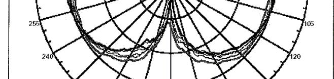

15 Page: 5 of 5 5 GHz band
16 Page: 6 of 6 Larson dual band swivel mount dipole
17 Page: 7 of 7 5 Test results 82.a W52 & W53 bands 5. Frequency Tolerance Result values: Tolerance from nominal frequency: T amb : 27 C RH: 45 % U nom : 3.3 Vdc Voltage Ch 36 Ch 48 Ch 64 U nom U -% U +% Carrier frequency (MHz) Frequency tolerance (ppm) Carrier frequency (MHz) n.t.* n.t.* n.t.* Frequency tolerance (ppm) n.t.* n.t.* n.t.* Carrier frequency (MHz) n.t.* n.t.* n.t.* Frequency tolerance (ppm) n.t.* n.t.* n.t.* Measurement uncertainty * See remark in section 4.3 test conditions. +/- 2 khz Limit values: Under all test conditions 2 ppm
18 Page: 8 of Occupied Bandwidth (99 % channel power bandwidth) Result values: T amb : 27 C RH: 45 % U nom : 3.3 Vdc * RBW 3 khz Marker [T ] * RBW 3 khz Marker [T ] Ref dbm * tt 3 db * VBW 3 khz SWT 2 ms.2 dbm 5.55 GHz Ref dbm * tt 3 db * VBW 3 khz SWT 2 ms dbm 5.25 GHz OBW 6.6 MHz OBW 6.6 MHz PK - T T2 Temp [T OBW] -4.5 dbm 5.77 GHz Temp 2 [T OBW] dbm GHz B PK - T T2 Temp [T OBW] -2.6 dbm GHz Temp 2 [T OBW] dbm GHz B Center 5.8 GHz 5 MHz/ Span 5 MHz Center 5.24 GHz 5 MHz/ Span 5 MHz Date: 4.JUL.28 5:34:2 Ch 36: occupied bandwidth 6.6 MHz * RBW 3 khz Marker [T ] * VBW 3 khz -47. dbm Ref 2 dbm * tt 3 db SWT 2 ms GHz Date: 4.JUL.28 6:26:4 Ch 48: occupied bandwidth 6.6 MHz OBW 6.6 MHz T T2 Temp [T OBW] -4.4 dbm S * GHz Temp 2 [T OBW] dbm GHz - Center 5.32 GHz 5 MHz/ Span 5 MHz Date:.JUL.28 5:56:3 Ch 64: occupied bandwidth 6.6 MHz Measurement uncertainty ± 96 khz Limit values: Under all test conditions Occupied bandwidth: 8 MHz Number of carriers: The total number of subcarriers in one channel OFDM is 52. There is no subcarrier at the channel center frequency (therefore there are 53 subcarrier frequencies but only 52 are used in a given channel). The measured occupied bandwidth varies is 6.6 MHz. 6.6 MHz / 53 =.3 Within a bandwidth of MHz there are at least 3 subcarriers. This complies with the requirement of at least subcarrier.
19 Page: 9 of Spurious emissions transmitter Result values: T amb : 27 C RH: 45 % U nom : 3.3 Vdc * RBW khz Marker [T ] * RBW MHz Marker [T ] Ref 2 dbm * tt 3 db * VBW khz SWT ms dbm. GHz Ref 2.9 dbm * tt 3 db * VBW MHz SWT 9 ms 3.65 dbm GHz Offset.9 db LIMIT CHECK PSS LIMIT CHECK PSS S * - S * - JPN5GHz JPN5GHz - - Start MHz 99 MHz/ Stop GHz Start GHz 436 MHz/ Stop 5.36 GHz Date: 3.JUL.28 7:9: Date: 3.JUL.28 7:3:4 Ch 36 TX * RBW MHz Marker [T ] Ch 36 TX * RBW MHz Marker [T ] Ref 2.9 dbm * tt 3 db * VBW MHz SWT 2 ms 7.3 dbm GHz Ref 23.2 dbm * tt 3 db * VBW MHz SWT 26 ms dbm GHz Offset.9 db LIMIT CHECK PSS Offset 3.2 db LIMIT CHECK PSS S * - S * - JPN5GHz JPN5GHz - Start 5 GHz 4 MHz/ Stop 5.4 GHz Start 5.4 GHz.286 GHz/ Stop 8 GHz Date: 3.JUL.28 7:5:22 Ch 36 TX Measurement uncertainty Date: 3.JUL.28 7:7:24 Ch 36 TX +2.4/-2.7 db
20 Page: 2 of 2 Result values: T amb : 27 C RH: 45 % U nom : 3.3 Vdc * RBW khz Marker [T ] * RBW MHz Marker [T ] Ref 2 dbm * VBW khz * tt 3 db SWT ms LIMIT CHECK PSS dbm MHz Ref 2.9 dbm Offset.9 db * VBW MHz * tt 3 db SWT 9 ms LIMIT CHECK PSS 6.63 dbm GHz S * - S * - JPN5GHz JPN5GHz - - Start MHz 99 MHz/ Stop GHz Start GHz 436 MHz/ Stop 5.36 GHz Date: 3.JUL.28 6:59:4 Date: 3.JUL.28 6:53:7 Ch 48 TX * RBW MHz Marker [T ] Ch 48 TX * RBW MHz Marker [T ] Ref 2.9 dbm Offset.9 db * VBW MHz * tt 3 db SWT 2 ms LIMIT CHECK PSS 7.77 dbm GHz Ref 23.2 dbm Offset 3.2 db * VBW MHz * tt 3 db SWT 26 ms LIMIT CHECK PSS 8.8 dbm GHz S * - S * - JPN5GHz JPN5GHz - Start 5 GHz 4 MHz/ Stop 5.4 GHz Start 5.4 GHz.286 GHz/ Stop 8 GHz Date: 3.JUL.28 6:5:5 Ch 48 TX Measurement uncertainty Date: 3.JUL.28 6:55:5 Ch 48 TX +2.4/-2.7 db
21 Page: 2 of 2 T amb : 27 C RH: 45 % U nom : 3.3 Vdc * RBW khz * RBW MHz Marker [T ] Ref 2 dbm * VBW khz * tt 3 db SWT ms LIMIT CHECK PSS Ref 2.9 dbm Offset.9 db * VBW MHz * tt 3 db SWT 9 ms LIMIT CHECK PSS 4.74 dbm GHz S * - S * - JPN5GHz JPN5GHz - - Start MHz 99 MHz/ Stop GHz Start GHz 436 MHz/ Stop 5.36 GHz Date: 3.JUL.28 5:22:37 Date: 3.JUL.28 5:3:2 Ch 64 TX * RBW MHz Marker [T ] Ch 64 TX * RBW MHz Marker [T ] Ref 2.9 dbm Offset.9 db * VBW MHz * tt 3 db SWT 2 ms LIMIT CHECK PSS 5.7 dbm GHz Ref 23.2 dbm Offset 3.2 db * VBW MHz * tt 3 db SWT 26 ms LIMIT CHECK PSS 8.2 dbm GHz S * - S * - JPN5GHz JPN5GHz - Start 5 GHz 4 MHz/ Stop 5.4 GHz Start 5.4 GHz.286 GHz/ Stop 8 GHz Date: 3.JUL.28 5:6:43 Ch 64 TX Measurement uncertainty +2.4/-2.7 db Date: 3.JUL.28 5:2:39 CH 64 TX Limit values: Transmitter operating < 54 MHz: - 26 dbm/mhz > 528 MHz: - 26 dbm/mhz
22 Page: 22 of Out-band emission power Result values: T amb : 27 C RH: 45 % U nom : 3.3 Vdc * RBW 3 khz * RBW 3 khz.jul 8 5:6 Ref 22 dbm * tt 3 db * VBW 3 khz SWT 2 ms.jul 8 5:2 Ref 22 dbm * tt 3 db * VBW 3 khz SWT 2 ms 2 Offset 5.9 db LIMIT CHECK PSS B 2 Offset 5.9 db LIMIT CHECK PSS B PK PK JPOUTPR - - JPOUTBND Center 5.49 GHz 2 MHz/ Span 2 MHz Center GHz 2 MHz/ Span 2 MHz SUBSTITUTED VLUE: 242. MHz SUBSTITUTED VLUE: 242. MHz Date:.JUL.28 5:6:55 Date:.JUL.28 5:2:46 Ch 36 TX * RBW 3 khz Marker [T ] Ch 48TX.Jul 8 4:57 Ref 22 dbm 2 Offset 5.9 db PK * VBW 3 khz * tt 3 db SWT 2 ms LIMIT CHECK PSS dbm 5.6 GHz B.Jul 8 7: Ref 22 dbm 2 Offset 5.9 db PK * RBW 3 khz * VBW 3 khz * tt 3 db SWT 2 ms LIMIT CHECK PSS B - - JPLEKPW W53OUTBD Center 5.26 GHz 2 MHz/ Span 2 MHz Center 5.34 GHz 5 MHz/ Span 5 MHz SUBSTITUTED VLUE: 242. MHz Date:.JUL.28 4:57:36 Ch 52 TX Measurement uncertainty Date:.JUL.28 7::43 Ch 64 TX +2.4/-2.7 db
23 Page: 23 of 23 Limit values W52 band: Frequency band Deviation frequency (f) from 524MHz EIRP MHz 98- MHz 2.5µW/MHz or less MHz 9-98MHz 5µW/MHz or less MHz - MHz MHz - 2MHz MHz MHz -(f-9) mw/mhz or less --(8/9)(f) mw/mhz or less -.8-(6/5)(f) mw/mhz or less MHz MHz 2.5µW/MHz or less Limit values W53 band: Frequency band Deviation frequency (f) from 526MHz EIRP MHz MHz 2.5µW/MHz or less MHz MHz MHz - 2MHz MHz - MHz -.8-(6/5)(f) mw/mhz or less - -(8/9)(f-) mw/mhz or less -(f-9) mw/mhz or less MHz 9 - MHz 2.5µW/MHz or less
24 Page: 24 of djacent channel power tolerance Result values: CH 36 Ref.9 dbm * tt 2 db * RBW 3 khz * VBW 3 khz SWT 2 ms Marker [T ] dbm GHz Offset.9 db - RM * - Center 5.8 GHz MHz/ Span MHz Tx Channel Bandwidth 8 MHz Power 2.5 dbm djacent Channel Bandwidth 8 MHz Lower db Spacing 2 MHz Upper db lternate Channel Bandwidth 8 MHz Lower db Spacing 4 MHz Upper db
25 Page: 25 of 25 CH 48 Ref.9 dbm * tt 2 db * RBW 3 khz * VBW 3 khz SWT 2 ms Marker [T ] dbm 5.9 GHz Offset.9 db - RM * - Center 5.24 GHz MHz/ Span MHz Tx Channel Bandwidth 8 MHz Power 4.7 dbm djacent Channel Bandwidth 8 MHz Lower db Spacing 2 MHz Upper db lternate Channel Bandwidth 8 MHz Lower db Spacing 4 MHz Upper db
26 Page: 26 of 26 CH 64 Ref.9 dbm * tt 2 db * RBW 3 khz * VBW 3 khz SWT 2 ms Marker [T ] dbm 5.27 GHz Offset.9 db - RM * - Center 5.32 GHz MHz/ Span MHz Tx Channel Bandwidth 8 MHz Power 4.29 dbm djacent Channel Bandwidth 8 MHz Lower db Spacing 2 MHz Upper db lternate Channel Bandwidth 8 MHz Lower db Spacing 4 MHz Upper db ** These test results are conducted measurements. ntenna gain is not related to this measurement. Limit values: Under all test conditions Mean Power 2 MHz distance of carrier: Mean Power 4 MHz distance of carrier: -25 dbc dbc
27 Page: 27 of ntenna Power Result values: T amb : 27 C RH: 45 % U nom : 3.3 Vdc Voltage ch 36 ch 48 ch 64 U nom U -% U +% Conducted power (dbm/mhz) Deviation from rated power (%) Radiated power (mw/mhz) ** Conducted power (dbm) n.t.* n.t.* n.t.* Radiated power (mw/mhz) n.t.* n.t.* n.t.* Conducted power (dbm) n.t.* n.t.* n.t.* Radiated power (mw/mhz) n.t.* n.t.* n.t.* Measurement uncertainty * See remark in section 4.3 test conditions. < 3.3 db ** The test results are valid for the 5. dbi gain antenna as specified in section 3.5 ntenna specifications. Note: the rated conducted power is.5 mw/mhz Limit values : Under all test conditions OFDM: mw/mhz (radiated) (tolerance +5% to - 5% from rated conducted power)
28 Page: 28 of Spurious emissions receiver Result values: T amb : 27 C RH: 45 % U nom : 3.3 Vdc * RBW khz Marker [T ] * RBW MHz Marker [T ] Ref dbm * tt db * VBW khz SWT ms.5 dbm. GHz Ref 3.2 dbm * tt db * VBW MHz SWT 34 ms dbm 5.82 GHz Offset 3.2 db - B - B PK PK D dbm D dbm - Start MHz 99 MHz/ Stop GHz Start GHz.7 GHz/ Stop 8 GHz Date: 4.JUL.28 7:6:9 Date: 4.JUL.28 7:2:9 Ch 36 RX * RBW khz Marker [T ] Ch 36 RX * RBW MHz Marker [T ] Ref dbm * tt db * VBW khz SWT ms dbm. GHz Ref 3.2 dbm * tt db * VBW MHz SWT 34 ms -6.5 dbm 5.25 GHz Offset 3.2 db - B - B PK PK D dbm D dbm - Start MHz 99 MHz/ Stop GHz Start GHz.7 GHz/ Stop 8 GHz Date: 4.JUL.28 6:56:47 Date: 4.JUL.28 6:54:4 Ch 48 RX Ch 48 RX
29 Page: 29 of 29 * RBW MHz Marker [T ] Ref dbm * tt db * RBW khz * VBW khz SWT ms Marker [T ] dbm. GHz Ref 3.2 dbm Offset 3.2 db * tt db * VBW MHz SWT 34 ms.8 dbm 5.38 GHz PK - B PK - B D dbm D dbm - Start GHz.7 GHz/ Stop 8 GHz Start MHz 99 MHz/ Stop GHz Date: 4.JUL.28 7:6:53 CH 64 Measurement uncertainty Date: 4.JUL.28 7:4:34 CH 64 2 GHz: +.7/-.9 db; > 2 GHz: +2.4/-2.7 db Limit values: Receiver operating MHz: MHz: 4 nw (-54 dbm) 2 nw (-47 dbm)
30 Page: 3 of Burst Length Result values: T amb : 27 C RH: 45 % U nom : 3.3 Vdc RBW 3 MHz Delta [T ] RBW 3 MHz Delta [T ] 29.Jul 8 6:42 Ref 2 dbm * tt 3 db * VBW 3 MHz SWT 2 ms db 288. µs Ref 2 dbm * tt 3 db * VBW 3 MHz SWT 2 ms db 372. µs 2 Marker [T ] 2 Marker [T ] 4.85 dbm -84. µs B 5.62 dbm as B PK * TRG PK * TRG - - TRG -4.2 dbm TRG dbm Center 5.8 GHz 2 µs/ Center 5.24 GHz 2 µs/ Date: 29.JUL.28 6:42:5 Date: 4.JUL.28 6:45:22 Ch 36: burst length 288 μsec. RBW 3 MHz Delta [T ] 29.Jul 8 6:35 * VBW 3 MHz db Ref 2 dbm * tt 3 db SWT 2 ms 288. µs Ch 48: burst length 372 μsec. 2 Marker [T ] 4.83 dbm as B PK * TRG - TRG -4.2 dbm Center 5.32 GHz 2 µs/ Date: 29.JUL.28 6:35:2 Ch 64: burst length 288 μsec. Measurement uncertainty 4.5% Limit values: Transmitter operating 4 ms
31 Page: 3 of Carrier sense capability utomatic cessation of transmitting is required when the electric field strength is exceeding E (mv/m):.6 E = (mv/m) G 2 Pt n where: Pt = antenna power in W; G = gain (numeric); n = 2,, and 5 for 2 MHz, MHz and 5 MHz systems respectively Substituting the formula into the expression: converts to the expression: 2 2 E λ P cs = G 2π 4π (W) P n = log F Ptm log (dbm) 2 cs + where: P cs = carrier sense power in dbm; P tm = total antenna power in dbm; F = frequency in MHz; n = 2,, and 5 for 2 MHz, MHz and 5 MHz systems respectively For example, for channel 36 (58 MHz) this yields: P = log log (2/2) = dbm cs Results: Channel Limit (dbm) Result (dbm) Margin w.r.t. to limit (db) 58 MHz MHz MHz
32 Page: 32 of 32 6 Test results 82.b 6. Frequency Tolerance Result values: Tolerance from nominal frequency: T amb : 27 C RH: 45 % U nom : 3.3 Vdc Voltage Ch Ch 7 Ch 4 U nom U -% U +% Carrier frequency (MHz) Frequency tolerance (ppm) Carrier frequency (MHz) n.t.* n.t.* n.t.* Frequency tolerance (ppm) n.t.* n.t.* n.t.* Carrier frequency (MHz) n.t.* n.t.* n.t.* Frequency tolerance (ppm) n.t.* n.t.* n.t.* Measurement uncertainty * See remark in section 4.3 test conditions. +/- 2 khz Limit values: Under all test conditions 5 ppm
33 Page: 33 of Occupied Bandwidth (99 % channel power bandwidth) Result values: T amb : 27 C RH: 45 % U nom : 3.3 Vdc * RBW 3 khz Marker [T ] * RBW 3 khz Marker [T ] Ref 2 dbm * tt 3 db * VBW 3 khz SWT 2.5 ms.25 dbm GHz Ref 2 dbm * tt 3 db * VBW 3 khz SWT 2.5 ms dbm GHz OBW 2.6 MHz OBW 2.6 MHz T T2 Temp [T OBW] dbm T T2 Temp [T OBW] dbm S * GHz Temp 2 [T OBW] -4.8 dbm GHz S * GHz Temp 2 [T OBW] dbm GHz - - Center 2.42 GHz 5 MHz/ Span 5 MHz Center GHz 5 MHz/ Span 5 MHz Date: 3.JUN.28 3:37:4 Ch : occupied bandwidth 2.6 MHz * RBW 3 khz Marker [T ] * VBW 3 khz dbm Ref 2 dbm * tt 3 db SWT 2.5 ms GHz Date: 3.JUN.28 3:35:3 Ch 7: occupied bandwidth 2.6 MHz OBW 8.5 MHz T Temp [T OBW] T dbm S * GHz Temp 2 [T OBW] dbm GHz - Center GHz 5 MHz/ Span 5 MHz Date: 3.JUN.28 3:4:42 Ch 4: occupied bandwidth 8.5 MHz Measurement uncertainty ± 96 khz Limit values: Under all test conditions Occupied bandwidth: 8 MHz
34 Page: 34 of 34 Number of carriers: The total number of subcarriers in one channel OFDM is 52. There is no subcarrier at the channel center frequency (therefore there are 53 subcarrier frequencies but only 52 are used in a given channel). The measured occupied bandwidth varies between 7.8 MHz and 7.92 MHz. 7.8 MHz / 53 =.32, 7.88 MHz / 53 =.34. Within a bandwidth of MHz there are at least 3 subcarriers. This complies with the requirement of at least subcarrier.
35 Page: 35 of Occupied Bandwidth (9 % channel power bandwidth) Result values: T amb : 27 C RH: 45 % U nom : 3.3 Vdc * RBW 3 khz Marker [T ] * RBW 3 khz Marker [T ] Ref 2 dbm * tt 3 db * VBW 3 khz SWT 2.5 ms dbm GHz Ref 2 dbm * tt 3 db * VBW 3 khz SWT 2.5 ms dbm GHz T T2 OBW 9.4 MHz T T2 OBW 9.4 MHz Temp [T OBW] 2.7 dbm Temp [T OBW] 2.58 dbm S * GHz Temp 2 [T OBW] 2.98 dbm GHz S * GHz Temp 2 [T OBW] 2.48 dbm GHz - - Center 2.42 GHz 5 MHz/ Span 5 MHz Center GHz 5 MHz/ Span 5 MHz Date: 3.JUN.28 3:38:59 Ch : occupied bandwidth 9.4 MHz Spreading factor: 9.4/.375 = 6.8 * RBW 3 khz Marker [T ] * VBW 3 khz dbm Ref 2 dbm * tt 3 db SWT 2.5 ms GHz Date: 3.JUN.28 3:34: Ch 7: occupied bandwidth 9.4 MHz Spreading factor: 9.4 /.375 = 6.8 T T2 OBW 4.9 MHz Temp [T OBW].97 dbm S * GHz Temp 2 [T OBW].5 dbm GHz - Center GHz 5 MHz/ Span 5 MHz Date: 3.JUN.28 3:32:22 Ch 4: occupied bandwidth 4.9 MHz Spreading factor: 4.9/.375 =.8 Measurement uncertainty ± 96 khz Limit values: Under all test conditions Spreading factor: 5 ( MHz); ( MHz)
36 Page: 36 of Spurious emissions transmitter Result values: T amb : 27 C RH: 45 % U nom : 3.3 Vdc * RBW khz Marker [T ] * RBW MHz Marker [T ] Ref 3 dbm * tt 4 db * VBW khz SWT ms.93 dbm. GHz Ref 3 dbm * tt 4 db * VBW MHz SWT ms dbm 2.4 GHz S * S * JPT 492JPT Start MHz 99 MHz/ Stop GHz Start GHz 4 MHz/ Stop 2.4 GHz Date: 3.JUN.28 2:4:4 Date: 3.JUN.28 2:2:2 Ch. GHz * RBW MHz Marker [T ] Ch 2.4 GHz * RBW MHz Marker [T ] Ref 3.5 dbm * tt 4 db * VBW MHz SWT 5 ms 6.9 dbm GHz Ref 3.5 dbm * tt 4 db * VBW MHz SWT 5 ms.9 dbm GHz Offset.5 db Offset.5 db S * S * JPT 492JPT Start 2.38 GHz 2 MHz/ Stop 2.5 GHz Start 2.4 GHz 56 MHz/ Stop 8 GHz Date: 3.JUN.28 :57:28 Date: 3.JUN.28 2::5 Ch GHz Measurement uncertainty Ch GHz +2.4/-2.7 db
37 Page: 37 of 37 Result values: T amb : 27 C RH: 45 % U nom : 3.3 Vdc * RBW khz Marker [T ] * RBW MHz Marker [T ] Ref 3 dbm * tt 4 db * VBW khz SWT ms dbm MHz Ref 3 dbm * tt 4 db * VBW MHz SWT ms dbm 2.4 GHz S * S * JPT 492JPT Start MHz 99 MHz/ Stop GHz Start GHz 4 MHz/ Stop 2.4 GHz Date: 3.JUN.28 2:3:7 Date: 3.JUN.28 2::3 Ch 7. GHz * RBW MHz Marker [T ] Ch GHz * RBW MHz Marker [T ] Ref 3.5 dbm * tt 4 db * VBW MHz SWT 5 ms 7.9 dbm GHz Ref 3.5 dbm * tt 4 db * VBW MHz SWT 5 ms 7.3 dbm GHz Offset.5 db Offset.5 db S * S * JPT 492JPT Start 2.38 GHz 2 MHz/ Stop 2.5 GHz Start 2.4 GHz 56 MHz/ Stop 8 GHz Date: 3.JUN.28 2:7:27 Date: 3.JUN.28 2:9:42 Ch GHz Measurement uncertainty Ch GHz +2.4/-2.7 db
38 Page: 38 of 38 T amb : 27 C RH: 45 % U nom : 3.3 Vdc * RBW khz Marker [T ] * RBW MHz Marker [T ] Ref 3 dbm * tt 4 db * VBW khz SWT ms dbm. GHz Ref 3 dbm * tt 4 db * VBW MHz SWT ms dbm 2.4 GHz S * S * - - JPN492 JPN492 Start MHz 99 MHz/ Stop GHz Start GHz 4 MHz/ Stop 2.4 GHz Date: 3.JUN.28 3:28:59 Date: 3.JUN.28 3:27:26 Ch 4. GHz * RBW MHz Marker [T ] Ch GHz * RBW MHz Marker [T ] Ref 3.5 dbm * tt 4 db * VBW MHz SWT 5 ms 5.37 dbm GHz Ref 3.5 dbm * tt 4 db * VBW MHz SWT 2 ms 6.27 dbm GHz Offset.5 db Offset.5 db S * S * - - JPN492 JPN492 Center 2.44 GHz 2 MHz/ Span 2 MHz Start 2 GHz 6 MHz/ Stop 8 GHz Date: 3.JUN.28 3:23:49 Date: 3.JUN.28 3:25:52 Ch GHz Measurement uncertainty Ch GHz +2.4/-2.7 db Limit values: Transmitter operating CH - 3 CH 4 Below 2387MHz : 2.5µW/MHz 2387 to 24MHz : 25µW/MHz through MHz : 25µW/MHz Over MHz : 2.5µW/MHz Below 2458MHz : 2.5µW 2458 to 247MHz : 25µW 2497 through 25MHz : 25µW Over 25MHz : 2.5µW
39 Page: 39 of ntenna Power Result values: T amb : 22 C RH: 43 % Voltage ch ch 7 ch 4 Conducted power (dbm/mhz) U nom U -% U +% Deviation from rated power (%) Radiated power (dbm/mhz) ** Conducted power (dbm) * n.t.* n.t.* n.t.* Radiated power (mw/mhz) * n.t.* n.t.* n.t.* Conducted power (dbm) * n.t.* n.t.* n.t.* Radiated power (mw/mhz) * n.t.* n.t.* n.t.* Measurement uncertainty < 3.3 db * See remark in section 4.3 test conditions. ** The test results are valid for dbi gain. Note: the rated conducted power is 2.5 mw/mhz Limit values : Under all test conditions DS: mw/mhz (tolerance +2 % to - 8 %)
40 Page: 4 of ngular width of principal radiation (WPR) The angular width of principal radiation (WPR), which follows from the antenna pattern specifications, shall satisfy the expression 36/ degrees. To be assessed: WPR < 36/ (degrees) represents the value determined by dividing the equivalent isotropic radiated power by the value obtained by applying an antenna power with the mean power of mw to the transmitting antenna with its absolute gain being 2.4 dbi. Results: ch ch 7 ch 4 Radiated power (mw/mhz) Constant 4.94/6.4 < 6.53/6.4 < 2.2/6.4 < 36/ (degrees)
41 Page: 4 of Spurious emissions receiver Result values: T amb : 27 C RH: 45 % U nom : 3.3 Vdc * RBW khz * RBW MHz * VBW khz * VBW MHz Ref dbm * tt db SWT ms Ref.5 dbm * tt db SWT 4 ms Offset.5 db S * S * 492JPR 492JPR Start MHz 99 MHz/ Stop GHz Start GHz 7 MHz/ Stop 8 GHz Date:.JUL.28 :55:3 Date:.JUL.28 :59:46 Ch. GHz * RBW khz Ch 8 GHz * RBW MHz * VBW khz * VBW MHz Ref dbm * tt db SWT ms Ref.5 dbm * tt db SWT 4 ms Offset.5 db S * S * 492JPR 492JPR Start MHz 99 MHz/ Stop GHz Start GHz 7 MHz/ Stop 8 GHz Date:.JUL.28 :5:57 Date:.JUL.28 :49:4 Ch 7. GHz Ch 7 8 GHz
42 Page: 42 of 42 * RBW khz * RBW MHz * VBW khz * VBW MHz Ref dbm * tt db SWT ms Ref.5 dbm * tt db SWT 4 ms Offset.5 db S * S * 492JPR 492JPR Start MHz 99 MHz/ Stop GHz Start GHz 7 MHz/ Stop 8 GHz Date:.JUL.28 :42:4 Date:.JUL.28 :45:4 Ch 4. GHz Measurement uncertainty Ch 4 8 GHz 2 GHz: +.7/-.9 db; > 2 GHz: +2.4/-2.7 db Limit values: Receiver operating MHz: MHz: 4 nw (-54 dbm) 2 nw (-47 dbm)
43 Page: 43 of 43 7 Test results 82.g 7. Frequency Tolerance Result values: Tolerance from nominal frequency: T amb : 27 C RH: 45 % U nom : 3.3 Vdc Voltage Ch Ch 7 Ch 3 U nom U -% U +% Carrier frequency (MHz) Frequency tolerance (ppm) +3 Carrier frequency (MHz) n.t.* n.t.* n.t.* Frequency tolerance (ppm) n.t.* n.t.* n.t.* Carrier frequency (MHz) n.t.* n.t.* n.t.* Frequency tolerance (ppm) n.t.* n.t.* n.t.* Measurement uncertainty * See remark in section 4.3 test conditions. +/- 2 khz Limit values: Under all test conditions 5 ppm
44 Page: 44 of Occupied Bandwidth (99 % channel power bandwidth) Result values: T amb : 27 C RH: 45 % U nom : 3.3 Vdc * RBW 3 khz Marker [T ] * RBW 3 khz Marker [T ] Ref 2 dbm * tt 3 db * VBW 3 khz SWT 2.5 ms dbm GHz Ref 2 dbm * tt 3 db * VBW 3 khz SWT 2.5 ms 2.54 dbm GHz T T2 OBW 6.6 MHz Temp [T OBW] dbm T T2 OBW 6.6 MHz Temp [T OBW] -.3 dbm S * GHz Temp 2 [T OBW] -.87 dbm GHz S * GHz Temp 2 [T OBW] -2.9 dbm GHz - - Center 2.42 GHz 5 MHz/ Span 5 MHz Center GHz 5 MHz/ Span 5 MHz Date: 3.JUN.28 4:8:7 Ch : occupied bandwidth 6.6 MHz * RBW 3 khz Marker [T ] * VBW 3 khz 3.69 dbm Ref 2 dbm * tt 3 db SWT 2.5 ms GHz OBW 6.6 MHz T T2 Temp [T OBW] -2.8 dbm GHz S * - Temp 2 [T OBW] dbm GHz Date: 3.JUN.28 4:28:33 Ch 7: occupied bandwidth 6.6 MHz - Center GHz 5 MHz/ Span 5 MHz Date: 3.JUN.28 5:33:24 Ch 3: occupied bandwidth 6.6 MHz Measurement uncertainty ± 96 khz Limit values: Under all test conditions Occupied bandwidth: 8 MHz
45 Page: 45 of 45 Number of carriers: The total number of subcarriers in one channel OFDM is 52. There is no subcarrier at the channel center frequency (therefore there are 53 subcarrier frequencies but only 52 are used in a given channel). The measured occupied bandwidth varies between 7.8 MHz and 7.92 MHz. 7.8 MHz / 53 =.32, 7.88 MHz / 53 =.34. Within a bandwidth of MHz there are at least 3 subcarriers. This complies with the requirement of at least subcarrier.
46 Page: 46 of Occupied Bandwidth (9 % channel power bandwidth) Result values: T amb : 27 C RH: 45 % U nom : 3.3 Vdc * RBW 3 khz Marker [T ] * RBW 3 khz Marker [T ] Ref 2 dbm * tt 3 db T * VBW 3 khz SWT 2.5 ms T dbm GHz OBW 4.8 MHz Ref 2 dbm * tt 3 db T * VBW 3 khz SWT 2.5 ms T dbm GHz OBW 4.8 MHz Temp [T OBW] 2.6 dbm Temp [T OBW] 2.25 dbm S * GHz Temp 2 [T OBW] 2.6 dbm GHz S * GHz Temp 2 [T OBW].88 dbm GHz - - Center 2.42 GHz 5 MHz/ Span 5 MHz Center GHz 5 MHz/ Span 5 MHz Date: 3.JUN.28 4:5:56 Ch : occupied bandwidth 4.8 MHz Spreading factor: 4.8/.5 = 9.9 * RBW 3 khz Marker [T ] * VBW 3 khz 4.2 dbm Ref 2 dbm * tt 3 db SWT 2.5 ms GHz T T2 OBW 4.8 MHz Temp [T OBW] 2.69 dbm GHz S * - Temp 2 [T OBW] 2.24 dbm GHz Date: 3.JUN.28 4:27:6 Ch 7: occupied bandwidth 4.8 MHz Spreading factor: 4.8/.5 = Center GHz 5 MHz/ Span 5 MHz Date: 3.JUN.28 5:37: Ch 3: occupied bandwidth 4.8 MHz Spreading factor: 4.8/.5 = 9.9 Measurement uncertainty ± 96 khz Limit values: Under all test conditions Spreading factor: 5 ( MHz); ( MHz)
47 Page: 47 of Spurious emissions transmitter Result values: T amb : 27 C RH: 45 % U nom : 3.3 Vdc * RBW khz * RBW MHz Marker 2 [T ] Ref 3 dbm * tt 4 db * VBW khz SWT ms Ref 3 dbm * tt 4 db * VBW MHz SWT ms dbm 2.4 GHz Marker [T ] dbm.8764 GHz S * S * JPT 492JPT 2 Start MHz 99 MHz/ Stop GHz Start GHz 4 MHz/ Stop 2.4 GHz Date: 3.JUN.28 5::54 Date: 3.JUN.28 4:59:6 Ch. GHz * RBW MHz Marker [T ] Ch 2.4 GHz * RBW MHz Marker [T ] Ref 3.5 dbm * tt 4 db * VBW MHz SWT 5 ms.35 dbm GHz Ref 3.5 dbm * tt 4 db * VBW MHz SWT 5 ms.3 dbm 2.42 GHz Offset.5 db Offset.5 db S * S * JPT 492JPT Start 2.38 GHz 2 MHz/ Stop 2.5 GHz Start 2.4 GHz 56 MHz/ Stop 8 GHz Date: 3.JUN.28 4:55:3 Date: 3.JUN.28 4:57:3 Ch GHz Measurement uncertainty Ch GHz +2.4/-2.7 db
48 Page: 48 of 48 Result values: T amb : 27 C RH: 45 % U nom : 3.3 Vdc * RBW khz * RBW MHz Marker [T ] Ref 3 dbm * tt 4 db * VBW khz SWT ms Ref 2 dbm * tt 3 db * VBW MHz SWT ms dbm.8764 GHz S * S * JPT 492JPT - Start MHz 99 MHz/ Stop GHz Start GHz 4 MHz/ Stop 2.4 GHz Date: 3.JUN.28 4:38:29 Date: 3.JUN.28 4:3:6 Ch 7. GHz * RBW MHz Marker [T ] Ch GHz * RBW MHz Delta 2 [T ] Ref 3.5 dbm * tt 4 db * VBW MHz SWT 5 ms.7 dbm GHz Ref 3.5 dbm * tt 4 db * VBW MHz SWT 5 ms db GHz Offset.5 db Offset.5 db Marker [T ] 5.42 dbm GHz S * S * JPT 492JPT 2 Start 2.38 GHz 2 MHz/ Stop 2.5 GHz Start 2.4 GHz 56 MHz/ Stop 8 GHz Date: 3.JUN.28 4:33:3 Date: 3.JUN.28 4:36:44 Ch GHz Measurement uncertainty Ch GHz +2.4/-2.7 db
49 Page: 49 of 49 T amb : 27 C RH: 45 % U nom : 3.3 Vdc Ref 3 dbm * tt 4 db * RBW khz * VBW khz SWT ms Marker [T ] dbm. GHz Ref 3 dbm * tt 4 db * RBW MHz * VBW MHz SWT ms Marker [T ] dbm.8848 GHz S * S * JPT 492JPT Start MHz 99 MHz/ Stop GHz Start GHz 4 MHz/ Stop 2.4 GHz Date: 3.JUN.28 5:47:36 Date: 3.JUN.28 5:39:5 Ch 3. GHz Ref 3.5 dbm * tt 4 db * RBW MHz * VBW MHz SWT 5 ms Marker [T ].64 dbm GHz Ch GHz Ref 3.5 dbm * tt 4 db * RBW MHz * VBW MHz SWT 5 ms Marker [T ] 7.9 dbm GHz Offset.5 db Offset.5 db S * S * JPT 492JPT Start 2.38 GHz 2 MHz/ Stop 2.5 GHz Start 2.4 GHz 56 MHz/ Stop 8 GHz Date: 3.JUN.28 5:42:34 Ch GHz Measurement uncertainty Date: 3.JUN.28 5:45:26 Ch GHz +2.4/-2.7 db Limit values: Transmitter operating CH - 3 Below 2387MHz : 2.5µW/MHz 2387 to 24MHz : 25µW/MHz through MHz : 25µW/MHz Over MHz : 2.5µW/MHz
50 Page: 5 of ntenna Power Result values: T amb : 22 C RH: 43 % Voltage ch ch 7 ch 3 Conducted power (dbm/mhz) U nom U -% U +% Deviation from rated power (%) Radiated power (dbm/mhz) ** Conducted power (dbm) * n.t.* n.t.* n.t.* Radiated power (mw/mhz) * n.t.* n.t.* n.t.* Conducted power (dbm) * n.t.* n.t.* n.t.* Radiated power (mw/mhz) * n.t.* n.t.* n.t.* Measurement uncertainty < 3.3 db * See remark in section 4.3 test conditions. ** The test results are valid for dbi gain. Note: the rated conducted power is 2.5 mw/mhz Limit values : Under all test conditions DS: mw/mhz (tolerance +2 % to - 8 %)
51 Page: 5 of ngular width of principal radiation (WPR) The angular width of principal radiation (WPR), which follows from the antenna pattern specifications, shall satisfy the expression 36/ degrees. To be assessed: WPR < 36/ (degrees) represents the value determined by dividing the equivalent isotropic radiated power by the value obtained by applying an antenna power with the mean power of mw to the transmitting antenna with its absolute gain being 2.4 dbi. Results: ch ch 7 ch 3 Radiated power (mw/mhz) Constant 5.4/6.4 < 5.2/6.4 < 5./6.4 < 36/ (degrees)
52 Page: 52 of Spurious emissions receiver Result values: T amb : 27 C RH: 45 % U nom : 3.3 Vdc * RBW khz * RBW MHz Marker [T ] Ref dbm * tt db * VBW khz SWT ms Ref.5 dbm * tt db * VBW MHz SWT 4 ms dbm 2.4 GHz Offset.5 db S * S * 492JPR 492JPR Start MHz 99 MHz/ Stop GHz Start GHz 7 MHz/ Stop 8 GHz Date:.JUL.28 :2:32 Date:.JUL.28 :8:3 Ch. GHz * RBW khz Marker [T ] Ch 8 GHz * RBW MHz Marker [T ] Ref dbm * tt db * VBW khz SWT ms dbm MHz Ref.5 dbm * tt db * VBW MHz SWT 4 ms dbm 3.98 GHz Offset.5 db S * S * 492JPR 492JPR Start MHz 99 MHz/ Stop GHz Start GHz 7 MHz/ Stop 8 GHz Date:.JUL.28 :23:7 Date:.JUL.28 :25:2 Ch 7. GHz Ch 7 8 GHz
53 Page: 53 of 53 * RBW khz * RBW MHz Marker [T ] Ref dbm * tt db * VBW khz SWT ms Ref.5 dbm * tt db * VBW MHz SWT 4 ms dbm GHz Offset.5 db S * S * 492JPR 492JPR Start MHz 99 MHz/ Stop GHz Start GHz 7 MHz/ Stop 8 GHz Date:.JUL.28 :28:26 Date:.JUL.28 :26:36 Ch 3. GHz Measurement uncertainty Ch 3 8 GHz 2 GHz: +.7/-.9 db; > 2 GHz: +2.4/-2.7 db Limit values: Receiver operating MHz: MHz: 4 nw (-54 dbm) 2 nw (-47 dbm)
54 Page: 54 of 54 Used test equipment module Report number: Used test equipment module Item Test equipment Manufacturer Type Ident Used at par.: RF Measurement Equipment Spectrum nalyzer Rohde & Schwarz FSP TE 25 all 2 Signal Generator khz GHz Marconi 242 TE , 5.6, 5.9, 6., 6.5, 7., Power sensor Hewlett Packard 848 TE , 6.5, Power meter Hewlett Packard 437B TE , 6.5, Directional coupler Hewlett Packard 873C Te
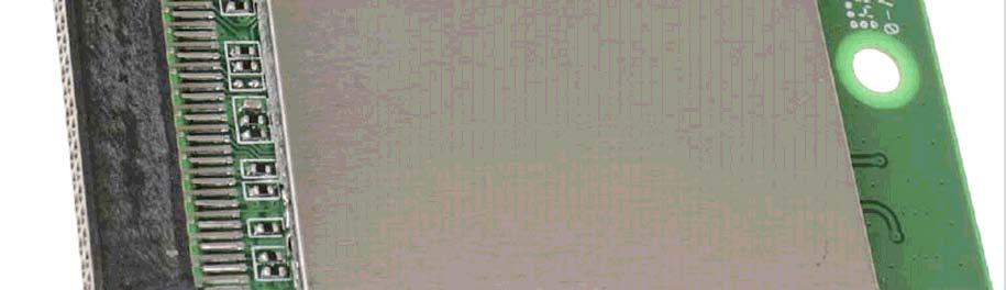
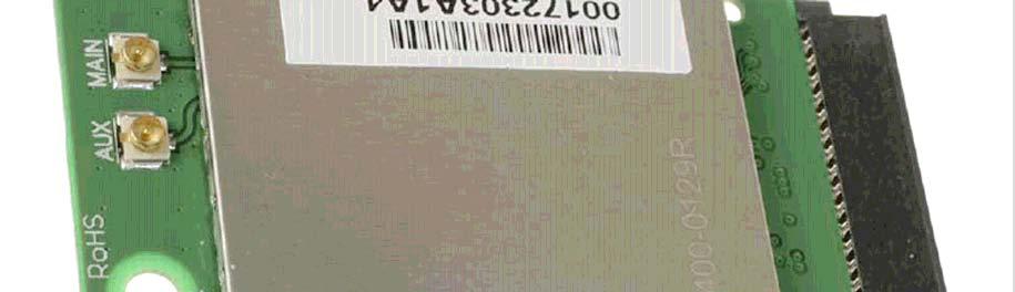
55 Page: 55 of 55 Photographs module Report number: Photographs module PHOTOGRPH : SDC-CFG, TOP...56 PHOTOGRPH 2: SDC-CFG, BOTTOM...57 PHOTOGRPH 3: SDC-CFG, DISSSEMBLED...58 PHOTOGRPH 4: SDC-CFG, PCB WITH TOP ND BOTTOM COVERS...59 PHOTOGRPH 5: SDC-CFG, PCB SIDE WITH COVER REMOVED...6 PHOTOGRPH 6: SDC-CFG, PCB SIDE 2 WITH COVER REMOVED...6 PHOTOGRPH 7: SDC-CFG, LIRD CENTURION NTENN...62 PHOTOGRPH 8: SDC-CFG, DIPOLE NTENN (LRSON)...63 PHOTOGRPH 9: SDC-CFG, DIPOLE NTENN (VOLEX)...64

56 Page: 56 of 56 Photographs module Report number: Photograph : SDC-CFG, top

57 Page: 57 of 57 Photographs module Report number: Photograph 2: SDC-CFG, bottom

58 Page: 58 of 58 Photographs module Report number: Photograph 3: SDC-CFG, disassembled view

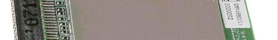


59 Page: 59 of 59 Photographs module Report number: Photograph 4: SDC-CFG, PCB with top and bottom covers


60 Page: 6 of 6 Photographs module Report number: Photograph 5: SDC-CFG, PCB side with cover removed


61 Page: 6 of 6 Photographs module Report number: Photograph 6: SDC-CFG, PCB side 2 with cover removed

62 Page: 62 of 62 Photographs module Report number: Photograph 7: SDC-CFG, Laird centurion antenna


63 Page: 63 of 63 Photographs module Report number: Photograph 8: SDC-CFG, dipole antenna (Larson)
64 Page: 64 of 64 Photographs module Report number: Photograph 9: SDC-CFG, dipole antenna (Volex)
RF Test Report: Airspan ib440 to 47CFR SC_TR_150_B
 RF Test Report: irspan ib44 to 47CFR5.247 FCC ID: O2J-iB44 SC_TR_5_B Prepared for: irspan Communications Ltd Capital Point, 33 Bath Road Slough, Berkshire SL 3UF Sulis Consultants Limited Mead House, Longwater
FCC REPORT (GSM & WCDMA)
") . Cover Page FCC REPORT (GSM & WCDM) Report No: CCISE84 pplicant: Garbarino S ddress of pplicant: Bolivar 874. CB (66) Equipment Under Test (EUT) Product Name: Model No.: Trade mark: Smart phone D5 Datsun
. Cover Page FCC REPORT (GSM & WCDM) Report No: CCISE84 pplicant: Garbarino S ddress of pplicant: Bolivar 874. CB (66) Equipment Under Test (EUT) Product Name: Model No.: Trade mark: Smart phone D5 Datsun
Shenzhen Zhongjian Nanfang Testing Co., Ltd.
 Report No: CCIS3667. Cover page FCC REPORT (Mobile Phone) Applicant: Address of Applicant: Equipment Under Test (EUT) NETLET ELECTRONICS (HONG KONG) LIMITED 2/F., San Toi Building,37-39 Connaught Road
TEST REPORT. REPORT NUMBER: B15W50007-FCC-RF_Rev4
 TEST REPORT REPORT NUMBER: B5W57-FCC-RF_Rev4 ON Type of Equipment: GPS Tracker Type of Designation: ll-in-one 3 Manufacturer: Presidio Networked Solutions, Inc. CCORDING TO FCC CFR Part 2, FREQUENCY LLOCTIONS
REPORT Datum/Date Beteckning/Reference Sida/Page
 2002-10-25 F219009-F24 1 (1) FCC ID: B5KPROJ1192211-1 Rev. 2003-01-16 Encl. 1 Description - Equipment Under Test (EUT) Equipment: Tx Frequency range: Tested Channel: WCDMA Base station transceiver 1900
Shenzhen Zhongjian Nanfang Testing Co., Ltd.
 Report No: CCISE8572 Cover Page FCC REPORT (Bluetooth) pplicant: ddress of pplicant: Equipment Under Test (EUT) GROUPSFIT 8/84 route de la Libération 7734 PONTULT COMBULT France Product Name: Model No.:
FCC REPORT. SZEM CR Monument Labs, Inc. Qingyuan Gadmei Electronics Technology Co., Ltd. Monument Photo Management Device
 No. Workshop, M-, Middle section, Science & Technology Park, Shenzhen, Guangdong, China 5857 Telephone: +86 () 755 26 253 Fax: +86 () 755 267 594 Email: ee.shenzhen@sgs.com Page: of 8 Cover page pplication
FCC PART 22, 74, 80 and 90 TEST REPORT. Shenzhen Excera Technology Co., Ltd.
 FCC PRT 22, 74, 8 and 9 TEST REPORT For Shenzhen Excera Technology Co., Ltd. 3rd Floor, Jiada R&D Building, No.5 Songpingshan Road, Hi-Tech Park North, Nanshan District, Shenzhen,China FCC ID: 2E6CER9VHF
EUROFINS PRODUCT SERVICE GMBH. Testing Cert # Compliance Test Report FCC PART 15 SUBPART C IC RSS 210 ISSUE 7
 EUROFINS PRODUCT SERVICE GMBH Testing Cert #1983.01 TEST- REPORT Compliance Test Report FCC PART 15 SUBPART C IC RSS 210 ISSUE 7 FCC ID: T7V1315 IC ID: 216Q-1315 Bluetooth module ENW89818C2JF PAN1315 TEST
TEST REPORT. Report Number: MPK-003B Project Number: G October 20, 2017
 TEST REPORT Report Number: 13224477MPK-3B Project Number: G13224477 October 2, 217 Testing performed on the FIBERGATEWAY Model Number: GR24BG FCC ID: 2ACJF-FGW-GR24BG to FCC Part 15, Subpart E For Altice
FCC PART 22H, PART 24E MEASUREMENT AND TEST REPORT. Shanghai AirM2M Communication Technology Co., Ltd
 FCC PART 22H, PART 24E MEASUREMENT AND TEST REPORT For Shanghai AirM2M Communication Technology Co., Ltd No. 666.East beijing road, Shanghai, China FCC ID: 2AEGG-AIR208 Report Type: Original Report Product
FCCC RF : ZTE APPLICANT EQUIPMENT BRAND NAME MODEL NAME FCC ID STANDARDD : WF722. The product was SPORTON. Page Number (KUNSHAN) INC.
 INC.") FCC RF Test Report 7 FCCC RF Test Report PPLICNT EQUIPMENT BRND NME MODEL NME FCC ID STNDRDD CLSSIFICTION : ZTE CORPORTION : HOME PHONE : ZTE : WF722 : SRQ-WF722 : FCC 47 CFR Part 2, 22(H), 24(E) : PCS
FCC RF Test Report 7 FCCC RF Test Report PPLICNT EQUIPMENT BRND NME MODEL NME FCC ID STNDRDD CLSSIFICTION : ZTE CORPORTION : HOME PHONE : ZTE : WF722 : SRQ-WF722 : FCC 47 CFR Part 2, 22(H), 24(E) : PCS
A Test Lab Techno Corp. FCC. RF Test Report. Product Type. : Mobile Hotspot. Applicant. : Netgear Inc.
 FCC RF Test Report Product Type Applicant : Mobile Hotspot : Netgear Inc. Address : 350 East Plumeria Drive, San Jose, CA 95134 Trade Name Model Number Test Specification : NETGEAR : AC810S-300 : FCC 47
TEST REPORT FROM RFI GLOBAL SERVICES LTD
 FROM RFI GLOBAL SERVICES LTD Test of: Blighter B422-HPNB Aux Unit FCC ID: UFQB400HPNBAUX To: FCC Part 90: 2010 Subpart F in accordance with RFI Test Plan RFI/REGE1/TP75565JD03 Test Report Serial No: RFI-RPT-RP76945JD15B
FCC PART TEST REPORT. HHC Changzhou Corp.
 FCC PART 15.249 TEST REPORT For HHC Changzhou Corp. No 61, Xinggang Road, Zhonglou District, Changzhou, Jiangsu, China, 213023 FCC ID: 2AEQWCB20HHC011 Report Type: Original Report Product Type: Control
TEST REPORT FROM RFI GLOBAL SERVICES LTD
 TEST REPORT FROM RFI GLOBAL SERVICES LTD Test of: D-MINI-2108-2019 FCC ID: NEO-DMINI21082019 To: FCC Parts 2.1046; 2.1049; 22.913(a); 22.917; 24.232; 24.238 & 15.107 3GPP TS 36.143 V10.3.0 This Test Report
TEST REPORT. Issued for:
 TEST REPORT FCC ID: 2PMJBV68PRO Product: Smart phone Model No.: BV68Pro dditional Model No.: N/ Trade Mark: Blackview Report No.: TCT823E47 Issued Date: Nov. 2, 28 Issued for: Shenzhen DOKE Electronic
EMC Test Report. Client: Continental Automotive Systems, Inc. Tested by: Fendy Liauw, Engineering Technician
 Test Report Number: 3953917EMC7 Rev: Page: 1 of 35 EMC Test Report Project Number: 3953917 Report Number: 3953917EMC7 Revision Level: Client: Continental Automotive Systems, Inc. Equipment Under Test:
FCC Test Report (Bluetooth)
") Report No.: T479F Page: of 52 FCC Test Report (Bluetooth) FCC ID : 8IVOOMBOX-ONGO pplicant : Shenzhen DIVOOM Technology Co., Ltd. 3, 2nd Floor, Block, Zhengxing Building, No. 33 Taizi Road, Shekou, Nanshan
Report No.: T479F Page: of 52 FCC Test Report (Bluetooth) FCC ID : 8IVOOMBOX-ONGO pplicant : Shenzhen DIVOOM Technology Co., Ltd. 3, 2nd Floor, Block, Zhengxing Building, No. 33 Taizi Road, Shekou, Nanshan
FCC ID: IMK-ILCISA EMI TEST REPORT
 15.247 Certification FCC ID: IMK-ILCISA EMI TEST REPORT On SYMPHONY ISA Card Prepared for Proxim 295 N. Bernardo Ave Mountain View, CA 94043 Tel: (650)960-1630 Fax: (650)960-0332 Prepared by Electronic
FCC PART TEST REPORT SHANGHAI MERIT TECHNOLOGY CORP.
 FCC PART 15.247 TEST REPORT For SHANGHAI MERIT TECHNOLOGY CORP. 1058 TAOGAN RD., SHESHAN TOWN, SONGJIANG DISTRICT, SHANGHAI, China FCC ID: XJ6MT-180H Report Type: Original Report Product Type: 4CH 2.4GHZ
FCC PART 15 TEST REPORT
 FCC PART 15 TEST REPORT No. I17Z60314SRD06 for HMD Global Oy Smart Phone TA-1033 with FCC ID: 2AJOTTA-1033 Hardware Version: 3 Software Version: 000C_3_050 Issued Date: 2017-04-17 Note:The test results
CONTENTS 1. GENERAL INFORMATION INTRODUCTION PRODUCT INFORMATION DESCRIPTION OF TESTS CHANNEL BANDWIDTH...
 Test Report Number : GETEC-E3-09-083 Page 2 / 33 CONTENTS. GENERAL INFORMATION...4 2. INTRODUCTION...5 3. PRODUCT INFORMATION...6 3. DESCRIPTION OF EUT...6 3.2 SUPPORT EQUIPMENT / CABLES USED...7 3.3 MODIFICATION
FCC PART 15C TEST REPORT FOR CERTIFICATION On Behalf of NYNE MULTIMEDIA INC. Bluetooth Speaker. Model Number: NYNE VIBE FCC ID: AWA-NYNEVIBE
 FCC PART 15C TEST REPORT FOR CERTIFICATION On Behalf of NYNE MULTIMEDIA INC. Bluetooth Speaker Model Number: NYNE VIBE FCC ID: AWA-NYNEVIBE Prepared for: NYNE MULTIMEDIA INC. 3451 LUNAR COURT, OXNARD,
EMC Test Report. Client: Crestron Electronics, Inc. Tested by: Jeremy O. Pickens, Senior EMC Engineer
 Test Report Number: 3919823EMC1 Rev. Page: 1 of 26 EMC Test Report Project Number: 3919823 Report Number: 3919823EMC1 Revision Level: Client: Crestron Electronics, Inc. Equipment Under Test: infinet EXTM
FCC PART 15 TEST REPORT
 FCC PART 15 TEST REPORT for Huawei Technologies Co.,Ltd tablet Model Name: T1-A1w FCC ID: QIST1-A1W with Hardware Version: SH1T1A1LM Software Version: T1-A1wV1R1C1 Issued Date: 15--15 TESTING CNAS L57
FCC REPORT Q6WBT * In the configuration tested, the EUT complied with the standards specified above.
 1 Cover Page Report No: CCIS12110026101 FCC REPORT Applicant: Address of Applicant: Equipment Under Test (EUT) GUANGDONG STEELMATE SECURITY CO., LTD Renan Street, Dong fu Road, Dongfeng Town,Zhongshan,
TEST REPORT. No. I17Z60153-GTE01. for. TCL Communication Ltd. GSM Quad band/umts 3 Band/LTE 4 Band Mobile phone. Model Name: A574BL FCC ID: 2ACCJB079
 TEST REPORT No. I7Z653-GTE for TCL Communication Ltd. GSM Quad band/umts 3 Band/LTE 4 Band Mobile phone Model Name: 574BL FCC ID: 2CCJB79 with Hardware Version: PIO Software Version: vg48 Issued Date:
TOBY-L200 GSM/UMTS/HSPA/LTE Data Module
 FCC Measurement/Technical Report on TOBY-L200 GSM/UMTS/HSPA/LTE Data Module FCC ID: XPYTOBYL200 IC:8595A-TOBYL200 Report Reference: MDE_UBLOX_1408_FCCd according to FCC Part 27, Subpart C Test Laboratory:
Description of the test object Appendix 1. Operation mode during measurements Appendix 1. Test setups Appendix 1. Purpose of test Appendix 1
 24--2 3P8658-F27 2 (2) Table of contents Description of the test object ppendix Operation mode during measurements ppendix Test setups ppendix Purpose of test ppendix RF power output conducted ppendix
Test Report. Applicant Address. : WALTOP International Corp. : 6F,No.19-1 Industry E.Rd.IV,Hsinchu Science Park,Hsin-Chu 30077,Taiwan,R.O.C.
 Test Report Product Name : Tablet: Wireless Tablet X86/X86; Dongle: Wireless Tablet Receiver X86/X86 Model No. : Tablet: RCK-T7, RCK-T7S; Dongle: RCK-T7R, RCK-T7RS FCC ID. : Tablet: UBBRCKT7, Dongle: UBBRCKT7R
TEST REPORT No
 D-PL-12076-01-00 TEST REPORT No. 3-20835062 Applicant Equipment under test Kathrein Automotive GmbH & Co. KG LTE Kompensator US; 6803145-01 218898-10 50110260 FCC-ID: 2ACC7LTECOMPB0 Test Standard(s) FCC
Report No.: CAT-012
 Conformance Test Report for EN301 406 V1.5.1 (2003-07) Digital Enhanced Cordless Telecommunic. (DECT); Harmonized EN for Digital Enhanced Cordless Telecommunications(DECT) covering essential requirements
T E S T - R E P O R T. No for PC24E-11-FC/R. RF-modem for wireless LAN. Agere Systems Nederland B.V.
 EMV-Prüfzentrum EMI/EMC-Testcenter Straubing, September 5, 2001 T E S T - R E P O R T No. 56305-10552-1 for RF-modem for wireless LAN Purpose of testing: To show compliance with FCC Code of Federal Regulations,
Item tested : KX-TGA641. Type of equipment : UPCS Handset FCC ID : ACJ96NKX-TGA640. Client : Panasonic Communications Co., Ltd.
 Test report no. : 3694-4 Item tested : KX-TG64 Type of equipment : UPCS Handset FCC ID : CJ96NKX-TG64 Client : Panasonic Communications Co., Ltd. FCC Part 5, subpart D Isochronous UPCS Device 92-93 MHz
CE DFS Test Report. Report No.: EY Page : 1 of 15 Report Version: Rev. 01
 CE DFS Test Report Equipment Model No. Brand Name Applicant Address : Radio Module : SSD45N : Laird Technologies : Laird Technologies : W66N220 Commerce Court, Cedarburg, Wisconsin 53012, USA Standard
SIGFOX RADIATED PERFORMANCE SPECIFICATION
 September 17 th 2018 SIGFOX RADIATED PERFORMANCE SPECIFICATION Public use Revision History Revision Number Date Author Change description 0.1 August 15 th, 2017 B.Ray Initial spec 0.2 October 5 th, 2017
Guangzhou Panyu Juda Car Audio Equipment Co.,Ltd. Bluetooth Speaker. Model Number: UB-SPB4M-101 FCC ID: ESXSPB4M
 FCC ID: ESXSPB4M FCC PART 15C TEST REPORT FOR CERTIFICATION On Behalf of Guangzhou Panyu Juda Car Audio Equipment Co.,Ltd. Bluetooth Speaker Model Number: UB-SPB4M-101 FCC ID: ESXSPB4M Prepared for : Guangzhou
FCC Radio Test Report
 Shenzhen Toby Technology Co., Ltd. Report No.: TB-FCC163268 Page: 1 of 153 FCC Radio Test Report FCC ID: 2AL8K-H5 Report No. : TB-FCC163268 Original Grant Applicant : NZS Inc. DBA Clary Icon Equipment
TEST REPORT. No. I17Z60314-GTE03. for. HMD Global Oy. Smart Phone. Model Name: TA-1033 FCC ID: 2AJOTTA with. Hardware Version: EVT
 TEST REPORT No. I7Z634-GTE3 for HMD Global Oy Smart Phone Model Name: T-33 FCC ID: 2JOTT-33 with Hardware Version: EVT Software Version: C_3_5 Issued Date: 27-5-9 Note : The test results in this test report
Out of Band Spurious Measurement for Bluetooth Modules
 Products: Signal Analyser FSIQ26/FSP13/FSU8/FSQ26 Out of Band Spurious Measurement for Bluetooth Modules This application notes describes the out of band Spurious emission measurement for Bluetooth modules
CE DFS Test Report. : abgn M.2 module w/usb interface (Refer to item for more details.) (Refer to item for more details.
 (Refer to item for more details.") CE DFS Test Report Equipment Model No. Brand Name Applicant : 802.11abgn M.2 module w/usb interface (Refer to item 1.1.1 for more details.) : M2US50NBT (Refer to item 1.1.1 for more details.) : Laird Technologies
CE DFS Test Report Equipment Model No. Brand Name Applicant : 802.11abgn M.2 module w/usb interface (Refer to item 1.1.1 for more details.) : M2US50NBT (Refer to item 1.1.1 for more details.) : Laird Technologies
Testing. Maker Works. Applicant: Model No.: FCC ID: Jun., May to 16. Date of Test: PASS* Test Result: Signature: Authorized. this report.
 1 Cover Page Shenzhen Zhongjian Nanfang Testing Co., Ltd. FCC REPORT Applicant: Address of Applicant: Maker Works Technology INC Building C3, Floor 4th, Zhiyuan, Xili, Nanshan District, ShenZhen 518057
Tests on 3G-Base Stations to TS with R&S Spectrum Analyzers and SMIQ Vector Signal Generator
 Products: FSP, FSIQ, FSU, FSQ, SMIQ Tests on 3G-Base Stations to TS 25.141 with R&S Spectrum Analyzers and SMIQ Vector Signal Generator This application note describes how to measure the various WCDMA
FCC Report. Beijing Visual World Technology Co.,Ltd.
 FCC Report Report No.: GTS201703000097F01 Applicant: Beijing Visual World Technology Co.,Ltd. Address of Applicant: 15th Floor and 17th Floor 1701-10A, Building 3, No. 10, Jiuxianqiao Road Jia, Chaoyang
S t a t e m e n t. of Opinion. No: /AA/00
 S t a t e m e n t of Opinion No: 08214062/AA/00 With respect to Chapter 10 of the Telecommunications Act of The Netherlands, Telefication declares that to our opinion the listed product complies with the
FCC TEST REPORT for Aeon Labs LLC. Aeon Minimote Model No.: DS03202B-ZWUS, DS03202W-ZWUS
 Page 1 of 22 FCC TEST REPORT for Aeon Labs LLC. Aeon Minimote Model No.: DS03202B-ZWUS, DS03202W-ZWUS Prepared for Address Prepared By Address : Aeon Labs LLC. : 121 Buckingham drive, unit36 santa claras
SIGFOX END- PRODUCT RADIATED TEST PLAN FOR SIGFOX READY TM CERTIFICATION
 May 23 th 2018 SIGFOX END- PRODUCT RADIATED TEST PLAN FOR SIGFOX READY TM CERTIFICATION Public use Revision History Revision Number Date Author Change description 0.1 August 15 th, 2017 B.Ray Initial spec
FCC PART TEST REPORT. Hantat Technology Ltd.
 FCC PRT 5.247 TEST REPORT For Hantat Technology Ltd. 3/F., C Building, Fuxinlin Industrial Park, Hangch,Xixiang Town, Banan District,Shenzhen,China,5826 FCC ID: V3NHB67 Report Type: Original Report Product
Bluetooth Tester CBT. Specifications. Specifications. Version January 2006
 Specifications Version 03.00 Bluetooth Tester CBT January 2006 Specifications CONTENTS UNIT SPECIFICATIONS...3 TIMEBASE TCXO...3 REFERENCE FREQUENCY INPUT...3 RF GENERATOR...3 RF ANALYZER...5 Power meter
RF TEST REPORT. Equipment Under Test (EUT): NOTE: The following sample(s) was/were submitted and identified by the client as
: NOTE: The following sample(s) was/were submitted and identified by the client as") 588 West Jindu Road, Xinqiao, Songjiang, 62 Shanghai, China Telephone: +86 () 2 69 5666 Fax: +86 () 2 69 5678 ee.shanghai@sgs.com Page: of 77 Cover Page pplication No.: pplicant: RF TEST REPORT SHEM752849CR
588 West Jindu Road, Xinqiao, Songjiang, 62 Shanghai, China Telephone: +86 () 2 69 5666 Fax: +86 () 2 69 5678 ee.shanghai@sgs.com Page: of 77 Cover Page pplication No.: pplicant: RF TEST REPORT SHEM752849CR
Report No.: CAT-012-1
 Conformance Test Report for EN301 406 V1.5.1 (2003-07) Digital Enhanced Cordless Telecommunic. (DECT); Harmonized EN for Digital Enhanced Cordless Telecommunications(DECT) covering essential requirements
FCC PART 15C TEST REPORT FOR CERTIFICATION On Behalf of. Guangzhou Panyu Juda Car Audio Equipment Co.,Ltd. CD/USB RADIO. Model Number: TY-CWU700
 FCC PART 15C TEST REPORT FOR CERTIFICATION On Behalf of Guangzhou Panyu Juda Car Audio Equipment Co.,Ltd. CD/USB RADIO Model Number: TY-CWU700 FCC ID: ESX-CWU700 Prepared for : Guangzhou Panyu Juda Car
CENTRE OF TESTING SERVICE INTERNATIONAL
 CENTRE OF TESTING SERVICE INTERNATIONAL OPERATE ACCORDING TO ISO/IEC 17025 IC TEST REPORT TEST REPORT NUMBER : CGZ3150202-00095-E A101,No.65,Zhuji Highway,Tianhe District,Guangzhou, Guangdong, China TEST
Spectrum Analyzer 1.6 GHz 3 GHz HMS-X
 Spectrum Analyzer 1.6 GHz 3 GHz 1 Basic Unit + 3 Options Your Spectrum Analyzer Key facts Frequency range: 100 khz to 1.6 GHz/3 GHz* 1 Spectral purity greater than -100 dbc/hz (at 100 khz) SWEEP from 20
Table of Contents 1. GENERAL INFORMATION SYSTEM TEST CONFIGURATION CONDUCTED EMISSIONS TEST RADIATED EMISSION TEST...
 Table of Contents. GENERL INFORMTION... 5. PRODUCT DESCRIPTION FOR EQUIPMENT UNDER TEST... 5.2 RELTED SUBMITTL(S) / GRNT (S)... 5.3 TEST METHODOLOGY... 8.4 EQUIPMENT MODIFICTIONS... 8.5 SUPPORT DEVICE...
Model 7330 Signal Source Analyzer Dedicated Phase Noise Test System V1.02
 Model 7330 Signal Source Analyzer Dedicated Phase Noise Test System V1.02 A fully integrated high-performance cross-correlation signal source analyzer from 5 MHz to 33+ GHz Key Features Complete broadband
ELECTRICAL TESTING FOR:
 ELECTRICAL TESTING 0839.01 Hermon Laboratories Ltd. Harakevet Industrial Zone, Binyamina 30500, Israel Tel. +972-4-6288001 Fax. +972-4-6288277 E-mail: mail@hermonlabs.com TEST REPORT ACCORDING TO: FCC
Spectrum Analyzer 1.6 GHz 3 GHz R&S HMS-X
 HMS-X_bro_de-en_3607-0181-3X_v0200.indd 1 Product Brochure 02.00 Test & Measurement Spectrum Analyzer 1.6 GHz 3 GHz R&S HMS-X 15.03.2016 15:24:06 1 Basic Unit + 3 Options Key facts Frequency range: 100
Akkreditiertes Prüflaboratorium
 Radio Satelite Communication Untertürkheimer Straße 6-10. D-66117 Saarbrücken Telefon: +49 (0)681 598-9100 Telefax: -9075 RSC11 issue test report consist of 15 Pages Page 1 (15) Akkreditiertes Prüflaboratorium
FCC Report (WIFI) Red Bear Company Limited. RedBear IoT phat 2ABXJ-PHAT-IOT
 Red Bear Company Limited. RedBear IoT phat 2ABXJ-PHAT-IOT") Report No.: GTS201607000065E01 FCC Report (WIFI) Applicant: Red Bear Company ed Address of Applicant: 1711 Block B, Wah Luen Industrial Centre, 15-21 Wong Chuk Yeung Street, Fo Tan, Hong Kong Equipment
Report No.: GTS201607000065E01 FCC Report (WIFI) Applicant: Red Bear Company ed Address of Applicant: 1711 Block B, Wah Luen Industrial Centre, 15-21 Wong Chuk Yeung Street, Fo Tan, Hong Kong Equipment
CENTRE OF TESTING SERVICE INTERNATIONAL OPERATE ACCORDING TO ISO/IEC FCC ID TEST REPORT
 CENTRE OF TESTING SERVICE INTERNATIONAL OPERATE ACCORDING TO ISO/IEC 17025 FCC ID TEST REPORT TEST REPORT NUMBER : CGZ3150520-00565-EF TEST REPORT For FCC ID 47 CFR PART 15 OCT, 2014 Report Reference No....
FCC Report (WIFI) Shenzhen SDMC Technology Co., Ltd 2AFC2-STB-1HD. * In the configuration tested, the EUT complied with the standards specified above.
 Shenzhen SDMC Technology Co., Ltd 2AFC2-STB-1HD. * In the configuration tested, the EUT complied with the standards specified above.") Report No.: GTSE15080158301 FCC Report (WIFI) Applicant: Shenzhen SDMC Technology Co., Ltd Address of Applicant: 7/F, W2-A Bld, Gaoxin S. Av. 4, Hi-tech Park, Nanshan, Shenzhen, China Equipment Under Test
Report No.: GTSE15080158301 FCC Report (WIFI) Applicant: Shenzhen SDMC Technology Co., Ltd Address of Applicant: 7/F, W2-A Bld, Gaoxin S. Av. 4, Hi-tech Park, Nanshan, Shenzhen, China Equipment Under Test
BT SOUND BAR. Model Number: AR2010 SBT2014, SBT2014XX, SBT2015,SBT2015XX, ER822FL FCC ID: RI5AR2010
 FCC ID: RI5AR2010 FCC PART 15C TEST REPORT FOR CERTIFICATION On Behalf of Dongguan Earson Audio Technology Co., Ltd BT SOUND BAR Model Number: AR2010 Additional Model:AR2010XX, AR3002, AR3002XX, SBT2014,
FCC TEST REPORT North Mathilda Avenue, Sunnyvale, California Advance Data Technology Corporation
 FCC TEST REPORT REPORT NO.: RF931119H01 NO.: RECEIVED: Nov. 19, 2004 TESTED: Dec. 22, 2004 to Jan. 05, 2005 ISSUED: Jan. 17, 2005 APPLICANT: ADDRESS: Juniper Networks 1194 North Mathilda Avenue, Sunnyvale,
Test Report. Product Name: Access Point Model No.: MS-6809 FCC ID: DoC
 Test Report Product Name: Access Point Model No.: MS-6809 FCC ID: DoC Applicant : MICRO-STAR INT L Co., LTD Address : No 69, Li-De st., Jung-He City, Taipei Hsien, Taiwan, R.O.C Date of Receipt : June
R&S FSW-K144 5G NR Measurement Application Specifications
 R&S FSW-K144 5G NR Measurement Application Specifications Data Sheet Version 01.00 CONTENTS Definitions... 3 Specifications... 4 Overview... 4 Assignment of option numbers to link modes... 4 Supported
CONFORMANCE TEST REPORT FOR FCC Part 15, subpart D
 FCC ID: G95-TC8706-C Sheet 1 of 88 CONFORMANCE TEST REPORT FOR FCC Part 15, subpart D Report No.: 13-01-MAS-215 Client: Product: Model: FCC ID: Manufacturer/supplier: Technicolor USA, Inc. Cable Modem
FCC Report (WIFI) Shenzhen Reo-link Digital Technology Co., Ltd B509, University Town Business Park LiShan Road, NanShan, Shenzhen, Guangdong, China
 Shenzhen Reo-link Digital Technology Co., Ltd B509, University Town Business Park LiShan Road, NanShan, Shenzhen, Guangdong, China") FCC Report (WIFI) Applicant: Address of Applicant: Manufacturer/y: Address of Manufacturer/y: Equipment Under Test (EUT) Product Name: Shenzhen Reo-link Digital Technology Co., Ltd B509, University Town
FCC Report (WIFI) Applicant: Address of Applicant: Manufacturer/y: Address of Manufacturer/y: Equipment Under Test (EUT) Product Name: Shenzhen Reo-link Digital Technology Co., Ltd B509, University Town
7000 Series Signal Source Analyzer & Dedicated Phase Noise Test System
 7000 Series Signal Source Analyzer & Dedicated Phase Noise Test System A fully integrated high-performance cross-correlation signal source analyzer with platforms from 5MHz to 7GHz, 26GHz, and 40GHz Key
Report On. FCC Testing of the Pace Plc 16x4 Hybrid Gateway Cable Set Top Box COMMERCIAL-IN-CONFIDENCE
 Report On FCC Testing of the Pace Plc 16x4 Hybrid Gateway Cable Set Top Box Document 75926325 Report 01 Issue 1 April 2014 TÜV SÜD Product Service, Octagon House, Concorde Way, Segensworth North, Fareham,
Application Note DT-AN DTU-315 Verification of Specifications
 DTU-315 Verification of Specifications APPLICATION NOTE January 2018 Table of Contents 1. Introduction... 3 General Description of the DTU-315... 3 Purpose of this Application Note... 3 2. Measurements...
BlueRadios BR-LE4.0-D2A N/A. BlueRadios, Inc.
 TEST REPORT of R&TTE (1999/5/EC ) Directive ETSI EN 300 328 V1.7.1: 2006 Product : Brand: Model: Model different: Applicant: Address: BT 4.0 Dual Mode Module BlueRadios BR-LE4.0-D2A N/A BlueRadios, Inc.
Spectrum Master. Compact Handheld Spectrum Analyzer. Technical Data Sheet
 Technical Data Sheet Spectrum Master Compact Handheld Spectrum Analyzer MS2712E MS2713E 100 khz to 4 GHz 100 khz to 6 GHz Introduction Anritsu introduces its next generation compact handheld Spectrum Analyzers
CERTIFICATION APPLICATION TEST REPORT
 BEC INCORPORATED CERTIFICATION APPLICATION TEST REPORT TEST STANDARDS: FCC Part 15 Subpart C, Section 15.247 Intentional Radiator ARRIS Model VMS4100 Set Top Box FCC ID: ACQ-VMS4100 REPORT BEC-1792-03
TEST REPORT. Test Report No. : UL-RPT-RP C V2.0. Date of Issue: 06 March 2018
 Test Report No. : UL-RPT-RP11913492-2216C V2.0 Manufacturer : Raspberry Pi (Trading) Ltd Model No. : Raspberry Pi 3 Model B+ FCC ID : 2ABCB-RPI3BP Technology : Bluetooth Low Energy Test Standard(s) : FCC
Project: IEEE P Working Group for Wireless Personal Area Networks (WPANs)
") Project: IEEE P802.15 Working Group for Wireless Personal Area Networks (WPANs) Title: [Radio Specification Analysis of Draft FSK PHY] Date Submitted: [11 March 2012] Source: [Steve Jillings] Company:
Project: IEEE P802.15 Working Group for Wireless Personal Area Networks (WPANs) Title: [Radio Specification Analysis of Draft FSK PHY] Date Submitted: [11 March 2012] Source: [Steve Jillings] Company:
RF Level Test System +20 dbm to 130 dbm
 NRVD Power Meter optional Therm. Sensor A B Power: >-15 dbm DUT (Signal Generator, Communication Tester) 1 MHz - 3.5/6 GHz +20 dbm... -130 dbm Diode Sensor Z4 Power: -15 to -40 dbm 6 db Power =< -40 dbm
MAXTECH, Inc. BRC-1000 Series. C-Band Redundant LNB Systems. Technology for Communications. System Block Diagrams
 MAXTECH, Inc. Technology for Communications BRC-1000 Series C-Band Redundant LNB Systems Introduction Redundant LNB systems minimize system downtime due to LNB failure by providing a spare LNB and an automatic
Advanced Test Equipment Rentals ATEC (2832)
") E stablished 1981 Advanced Test Equipment Rentals www.atecorp.com 800-404-ATEC (2832) Technical Datasheet Scalar Network Analyzer Model 8003-10 MHz to 40 GHz The Giga-tronics Model 8003 Precision Scalar
E stablished 1981 Advanced Test Equipment Rentals www.atecorp.com 800-404-ATEC (2832) Technical Datasheet Scalar Network Analyzer Model 8003-10 MHz to 40 GHz The Giga-tronics Model 8003 Precision Scalar
Application Note DT-AN-2115B-1. DTA-2115B Verification of Specifations
 DTA-2115B Verification of Specifations APPLICATION NOTE January 2018 Table of Contents 1. Introduction... 3 General Description of the DTA-2115B... 3 Purpose of this Application Note... 3 2. Measurements...
Table of Contents 5. NUMBER OF HOPPING CHANNEL APPLIED PROCEDURES / LIMIT TEST RESULTS 32
 Table of Contents. GENERL INFORMTION 3. GENERL DESCRIPTION OF EUT 4.2 FCILITIES ND CCREDITTIONS 5.3 DESCRIPTION OF TEST MODES 6.4 TBLE OF PRMETERS OF TEXT SOFTWRE SETTING 7.5 DESCRIPTION OF SUPPORT UNITS(CONDUCTED
FCC Test Report (Part 15C) WPT
 WPT") FCC Test Report (Part 15C) WPT Test Report no.: EMC_BO_002127 (v3.0) Date of Report: 14-Dec-2017 Number of pages: 15 Project support engineer: Frank Wittmann Test period: 02.10.-26.10.2017 Applicant: Manufacturer:
FCC Test Report (Part 15C) WPT Test Report no.: EMC_BO_002127 (v3.0) Date of Report: 14-Dec-2017 Number of pages: 15 Project support engineer: Frank Wittmann Test period: 02.10.-26.10.2017 Applicant: Manufacturer:
11 GHz MDD FIBER OPTIC LINK FEATURES TYPICAL APPLICATIONS
 11 GHz MDD FIBER OPTIC LINK FEATURES Small size Bandwidth to 11 GHz Plug-in optical connector No external control circuits required Transimpedance amplifier in both transmitter and receiver Custom transmitter
Certificate of Calibration
 Model Number 8720D Manufacturer Hewlett Packard Co Description Network analyzer 50MHz to 20GHz Serial Number US39150600 Options Installed 1D5 010 Date of Calibration 16 Sep 2014 Procedure STE-50114355-A.04.01
HMC7056. Block Upconverters / HPA's. Typical Applications. General Description. Features. Functional Block Diagram
 Typical Applications Features Compact Design Dual L Band Inputs Dual up conversion to ensure no phase inversion WR28 Output with Isolator PA Enable Digital Gain control Thermal Monitoring and Gain Compensation
OBSOLETE HMC7056. Block Upconverters / HPA's. Typical Applications. General Description. Features. Functional Block Diagram
 Typical Applications Features Compact Design Dual L Band Inputs Dual up conversion to ensure no phase inversion WR28 Output with Isolator PA Enable Digital Gain control Thermal Monitoring and Gain Compensation
Akkreditiertes Prüflaboratorium
 Radio Satellite Communication Untertürkheimer Straße 6-10. D-66117 Saarbrücken Telefon: +49 (0)681 598-9100 Telefax: -9075 RSC11 issue test report consist of 1 Pages Page 1 (1) Akkreditiertes Prüflaboratorium
R&S FPC1000 Spectrum Analyzer Specifications
 R&S FPC1000 Spectrum Analyzer Specifications year Data Sheet Version 01.00 CONTENTS Definitions... 3 Specifications... 4 Frequency... 4 Sweep time... 4 Bandwidth... 4 Level... 5 Trigger functions... 6
1Chapter INTRODUCTION. This chapter describes the CST-5000 C-Band satellite terminal, referred to in this manual as the CST-5000 (Figure 1-1).
.") 1Chapter 1. INTRODUCTION This chapter describes the CST-5000 C-Band satellite terminal, referred to in this manual as the CST-5000 (Figure 1-1). Figure 1-1. CST-5000 Single Thread System Rev. 9 1 1 1.1
1Chapter 1. INTRODUCTION This chapter describes the CST-5000 C-Band satellite terminal, referred to in this manual as the CST-5000 (Figure 1-1). Figure 1-1. CST-5000 Single Thread System Rev. 9 1 1 1.1
INSTRUCTION MANUAL MODEL 2710 SUBCARRIER DEMODULATOR
 INSTRUCTION MANUAL MODEL 2710 SUBCARRIER DEMODULATOR Data, drawings, and other material contained herein are proprietary to Cross Technologies, Inc., and may not be reproduced or duplicated in any form
CE DFS Test Report. : abgn PCI-E module
 CE DFS Test Report Equipment Model No. Brand Name Applicant Address : 802.11abgn PCI-E module : SDC-PE15N : Summit : Summit Data Communications, lnc. : 526 South Main Street Suite 805, Akron, Ohio, 44311
T E S T - R E P O R T. No for. SLG 42 MOBY Component
 Straubing, August 04, 1998 T E S T - R E P O R T No. 51905-80643-0 for SLG 42 MOBY Component Applicant: Purpose of Testing: Siemens AG To show compliance with FCC Rules Part 15, Subpart C section 15.209
Agilent 8560 E-Series Spectrum Analyzers
 Agilent 8560 E-Series Spectrum Analyzers Data Sheet 8560E 30 Hz to 2.9 GHz 8561E 30 Hz to 6.5 GHz 8562E 30 Hz to 13.2 GHz 8563E 30 Hz to 26.5 GHz 8564E 30 Hz to 40 GHz 8565E 30 Hz to 50 GHz 8565E SPECTRUM
ENGINEERING COMMITTEE
 ENGINEERING COMMITTEE Network Operations Subcommittee SCTE OPERATIONAL PRACTICE SCTE 222 2015 Useful Signal Leakage Formulas Title Table of Contents Page Number NOTICE 3 1. Scope 4 2. References 4 3. Abbreviations
FCC TEST REPORT D-LINK CORPORATION
 FCC TEST REPORT REPORT NO.: RF921014R02 MODEL NO.: DWL-120(refer to page 6 for other models) RECEIVED: October 14, 2003 TESTED: October 16 ~ October 17, 2003 APPLICANT: ADDRESS: D-LINK CORPORATION NO.8,
TEST REPORT. Test Report No. : UL-RPT-RP JD18L V2.0. Manufacturer : Neeo AG. Model No. : 6336-BRAIN FCC ID : 2AKK7-BR633601
 TEST REPORT Test Report No. : UL-RPT-RP11456397JD18L V2.0 Manufacturer : Neeo AG Model No. : 6336-BRAIN FCC ID : 2AKK7-BR633601 Test Standard(s) : FCC Part 15.207 1. This test report shall not be reproduced
Test. Report. : connectblue. Manufacturer. Model No. FCC ID. 1. This. 3. This. as UL. Date of Issue: 22 May Checked by: Sarah Williams
 Test Report TESTT REPORT No. : UL-RPT-RP86779JD03B V2.0 Manufacturer Model No. FCC ID IC Certification No. Test Standard(s) : connectblue : cb-0926-02 & cb-0926-03 : PVH0926 : 5325A-0926 : FCC Parts 15.
Calibrating the CMD Output Level for BER
 Ref Lvl -32 dbm -40-50 Marker 1 [T1] -35.50 dbm 5.000000 ms RBW 300 khz RF Att 0 db VBW 3 MHz SWT 5 ms Unit dbm 1 SUMMARY [T1] A RMS AVG -85.86 dbm SGL TRG -60-70 1RM -80 EXT -90-100 -110-120 -130 T1 T2
Measurements on GSM Base Stations According to Rec
 Measurements on GSM Base Stations According to Rec. 11.20 Application Note 1EF23_0L Subject to change 10 September 96, Josef Wolf / Roland Minihold Products: FSE incl. Option FSE-B7 1 Introduction The