8x2 UNIVERSAL SCALER MATRIX SWITCHER & EFFECT CONTROL
|
|
|
- Roland Wright
- 6 years ago
- Views:
Transcription


1 8 universal inputs 2 independent double outputs, VGA and DVI In/Out resolution up to UXGA and 1080p Seamless switching in Fading, Mixer or Cut Preview, PIP, Titling and Overlay functions Image parameter control Audio associated with video with volume adjustment IR, RS232 and Ethernet control DVIPRO1000 M 28/05/08 1 1
2 INSTALLATION AND USE OF THE DVIPRO1000 CONTENTS: 1.0 Overview Power supply Connections Basic functions Remote control functions Detailed Functions Programming menu RS 232 and Ethernet commands Firmware upgrade Technical data Notes 44 Please read this handbook carefully when installing the DVIPRO1000 unit. The manufacture shall not be held responsible for any damages caused by use, even correct, of its products. Product data and characteristics may be modified without prior notice. 2 2

3 1.0 OVERVIEW Thank you for buying this product. Check the contents of the packaging carefully. It contains: The DVIPRO1000 unit permits switching, on two independent, programmable outputs, of video and audio signals from eight different sources. In particular, for the video part: - IN1 and IN2: 2 inputs on connector VGA HDD15p. that can accept RGBHV, Component, YC and CVBS signals - IN3, IN4, IN5, IN6: 4 inputs on connector VGA HDD15p. or on triple BNC, that can accept RGBHV, Component, YC and CVBS signals - IN7: 1 input on connector DVI-I or on triple BNC, that can accept DVI, RGBHV (via adapter VGA-DVI), Component, YC and CVBS signals - IN8: 1 input on connector HDMI or on triple BNC that can accept HDMI, DVI (via DVI-HDMI adapter), Component, YC and CVBS signals. 3 3
4 The 2 outputs are completely independent. Each output is scalable in a wide set of formats and available both in DVI digital format and RGBHV analogue format on connector HDD15p. Each output channel permits concurrent display of 2 inputs, creating 2 independent windows, MAIN and PIP whose size and position can be set freely. The unit performs switching through the Fading, Mixer or Cut effect. Fade and Mixer time is programmable. These modes are available both in automatic and in mauial mode. A Preview function is also available to switch the image of OUT1 on OUT2. An Overlay function is also available which permits subtitling or overlay effects between images. The DVIPRO1000 features 8 different global preset memories that can be saved and recalled by the user. The basic commands for control of the machine are available from the machine keyboard with lighting keys, where an LCD display shows its complete status. Using the remote control, it is possible to access all the functions, including the programming menu. All functions can also be accessed via a RS232 serial interface and LAN connection. The related balanced stereo audio channel is associated to each input. Output volume can be regulated in digital mode for each single input and for each single output. The HDMI channel is fitted with a specific SPDIF internal decoder which is activated when the audio is contained in the HDMI stream. 4 4

5 2.0 POWER SUPPLY The DVIPRO1000 unit must be powered at Vac 50/60Hz using the cable provided. The socket of the cable must be inserted in the related panel plug to the left on the back of the unit. The panel plug is equipped with a fuse holder for 5X20 fuses. If the fuse blows, replace it with one of the same rating as specified on the back of the unit. All operations must be carried out by qualified personnel who must be informed of the risk of electric shock In some countries, the plug of the cable must be adapted to local standards. The wires are identified according to the following coding: - Brown PHASE (Identified with the letter L, may be red) - Blue NEUTRAL (Identified with the letter N, may be black) - Yellow/Green GROUND (Identified with the letter E, may be green) WARNING A ground connection is compulsory 5 5

6 EXAMPLE OF CONNECTION DVI 6 6
7 3.0 CONNECTIONS Connect the single inputs to the respective connector on the back of the DVIPRO1000. For inputs 1 and 2, available only on connector HDD15p, in the case of connection of Component, YC or CVBS signals, the specific VGA-5BNC type ADC201 adapter cable must be used on which correspondence is as follows: GREEN = CVBS, or Y of YC or Y of the component BLUE = C of the YC or Pb of the component RED = Pr of the component For inputs 3, 4, 5 and 6 available on connector HDD15p. and on 3 separate BNC, connect only one source for each input For inputs 7 and 8, available on connectors DVI-I, HDMI and 3 separate BNC, connect only one source for each input WARNING Never connect more than 1 source at a time to the universal inputs in order to prevent damage to the sources or to the DVIPRO1000 Connect the destinations to the related output connectors of the DVIPRO1000. Resolution can be set for each output.: the DVI and VGA channels of each output will have the same resolution and setting of the image. Connect the inputs and balanced audio outputs on the dedicated terminals. As regards the HDMI input, as the digital audio signal is already contained in the HDMI signal, it is not necessary to connect a separate audio signal on IN8 as the DVIPRO1000 is able to decode the audio present in the HDMI signal and convert this into a traditional analogue signal on the selected output. If a separate audio is to be associated with the 8 HDMI input, it is necessary to program the format of input IN8 as DVI instead of HDMI. 7 7
8 4.0 BASIC FUNCTIONS Power on the DVIPRO1000 using the switch on the rear panel. The unit will perform a StartUp phase lasting around 20 seconds, (during this phase the whole keyboard blinks red/green) at the end of which it will switch to the Default condition. The default setting, activated at initial power-on, is as follows: Input formats: In1 - input VGA In2 - input VGA In3 - input CVBS In4 - input CVBS In5 - input Component In6 - input Component In7 - input DVI In8 - input HDMI (embedded audio) Output resolutions Out1- resolution XGA PIP de-activated Out2 - resolution XGA PIP de-activated Channel selection MAIN channel - In1 (VGA) on OUT1 and OUT2 PIP channel - In3 (CVBS) on OUT1 and OUT2 Switching mode Fading PIP and Overlay Disabled 8 8

. If Pip is disabled, the red light brightness is lower.")
9 The main commands for functioning of the DVIPRO1000 can be carried out from the local keyboard. Machine keyboard lighting keys In order to give a better and quicker intellegibility of the system, each key has An internal red/green/yellow light, with the following scheme; - Keys from 1 to 8 for both the Out channels : in each row, the green light is for the Main input, while the red light is for the Pip input. During the switching phase, the new channel will blink. If both Main and Pip inputs are the same, then the light will be yellow (red+green). If Pip is disabled, the red light brightness is lower. In Mixer and cut modes, the channel Key will blink yellow during the preparing phase, then it will become green when it is ready to switch, - Format key : it will blink during the format selection, together with the channel key (1 to 8) in programmino. - Overlay key : red or green or yellow upon the state of the overlay on the channels (yellow = both channels) - Save/Recall key: yellow light during these modes - Preview key 1 2: it blinks yellow during the transfer of the configuration from OUT1 to OUT2 : also the interested channel keys of the second row will blink - Resolution key: green or red upon the channel which is interested in the resolution changing. (green OUT1, red OUT2) 9 9
10 4.1 Selection of output resolution - Volume keys: they flashes yellow for each volume variation. In the case of a mute condition, both the + and keys will be on (green for OUT1, red for OUT2, yellow for both channels) - Out channel key : the green light stands for the OUT1 channel, the red light for the OUT2 channel. The volume, resolution and overlay keys will be active for the selected output channel To define output resolution, proceed as follows: With the MODE key, select the output channel on which the new resolution is to be set according to the indications screen-printed beside the key. Then, press the RES key: an OSD menu is displayed in the output screen page with the list of the selectable resolutions, while the currently selected resolution will be shown on the LCD display. Continue to press the RES key until the resolution desired is highlighted on the LCD and on the video. After a brief pressure on the MODE key, the programming becomes effective and the machine will perform a restart cycle of around 10 seconds, at the end of which the new resolution will be activated. N.B. the VGA analogue output and the DVI digital output of the single output channel always have the same resolution
11 4.2 Definition of input format To define the format of the inputs, proceed as follows: Press the FORMAT key on the front panel of the machine and, at the same time, press the key relating to the input to be defined, using either the buttons relating to OUT1 or OUT2: each time the key of the input is pressed, the current assignment of the input will be shown on the LCD and on the video. In this way, it is possible to scroll all the possible formats that can be assigned. On releasing the FORMAT key, the DVIPRO1000 will make the programming operative and if, at that moment, the channel reprogrammed was displayed, will refresh the display. With regard to input 8, if this is used in HDMI format, the related digital audio stream inserted in the HDMI signal will be automatically decoded by the DVIPRO1000. If the audio is to be provided separately in analogue format on input 8 audio, input 8 must be programmed as DVI format. WARNING Format changing is possibile only in Fading Mode. In Mixer and Cut Mode the operation is not permitted 4.3 Source selection To select the inputs, use buttons 1 to 8 relating to outputs OUT1 and OUT2 on the front keyboard. Switching is performed in a programmable time of 0 to 3 seconds according to Fading, Mixer or Cut mode. If the input selected is VGA analogue format, at initial power-on of the machine, an automatic AUTOADJUST procedure will be performed for improved centering of the image on the screen: subsequent switching operations will not require this phase except in the case in which the format of the source in input is modified or if it is connected to a new VGA source. During this phase, the key of the interested channel will blink fast. 4.4 Activation of the PIP and selection of its source To activate the PIP on an output channel, proceed as follows: Press the key relating to the channel currently present on the MAIN; holding down the key, also press at the same time the key relating to the input that is to be displayed in PIP: the window will be activated to the bottom right. Subsequently, from the remote control or using serial commands, it will be possible to modify the size and position of the MAIN and PIP windows (see paragraph and paragraph 7.4). If repeated, the same operation to activate the PIP will cause de-activation of this
12 Example 1 : input 1 is on the MAIN. To activate input 3 in PIP, I press key 1 and then and at the same time key 3. Example 2 : on the MAIN I have input 1 and input 3 on the PIP. To switch the PIP input on 4, I press key 1 and then at the same time key 4. WARNING 1) Input 7 cannot be activated in the PIP window when this is programmed as DVI format 2) An input programmed as VGA cannot be activated in PIP if an input programmed as VGA is already present in the MAIN. In both cases, the DVIPRO1000 will display the NOT ALLOWED message 3) It is not possible to enable the PIP window when operating in MIXER or CUT mode. In this case, the DVIPRO1000 will display the ALREADY IN MIXER message
13 4.5 Other keyboard commands Volume adjustment For each single input, it is possible adjust volume in a scale from 0 to 33 steps corresponding to a change from MUTE to 0dB: to do this, using the MODE key, select the output channel desired, then use the VOL+ and VOL- keys for adjustment. The adjustment will be saved permanently and each input will have its associated output volume Overlay The OVR key can be used to activate machine Overlay mode, scrolling the various possible modes (see paragraph and paragraph 7.5) Saving and recall of presets Up 8 complete configurations can be saved as presets that can be recalled subsequently. To do this, press the SAVE/RECALL key and at the same time press a key from 1 to 8. The machine will confirm saving with a message on the OSD. To recall a preset, press again the SAVE/RECALL key and, at the same time, a key from 1 to 8 relating to the preset to be reloaded: the data of the preset saved will be loaded in the memory and the machine will switch to the new conditions after a StartUp cycle of around 20 seconds. The DVIPRO1000 maintains, as default memory, the last state that was active at the time of power-off preview 1 2 function: see chapter

14 4.6 LCD display The front panel of the machine includes an LCD display on which information regarding the current status of the system is displayed. In particular, the following are displayed for each output channel: SOURCE - the input selected on the MAIN channel FORMAT INPUT - the format of the input selected RESOL - the output resolution PIP SEC. SOURCE - the input selected as PIP channel AUDIO VOL - the audio volume of the channel (from 000 to 033) T FADING - switching mode (FADE, MIX or CUT, manual MIX or manual CUT)) followed by the timing value (from 1 to 6 for FADE and MIX) OVERLAY - enable of Overlay and type of OVERLAY set (from 1 to 5 or OFF)

15 5.0 REMOTE CONTROL FUNCTIONS An entire set of advanced functions and programming possibilities can be accessed via the IR remote control (or external interface). The remote control provides a certain number of functions available directly using the keys, plus a direct programming menu of the output format, a save/memorize menu and an advanced programming menu. WARNING The remote control is of the self-learning type. After inserting the batteries and each time these are changed, press the Set key for a few seconds followed by the key with the white border (Enter key) 15 15
16 5.1 Commands KEY FUNCTION COMMENT REFERENCE 1.8 OUT OUT 2 PIP OUT 1 PIP OUT 2 PIP CH OUT 1 PIP CH OUT 2 MUTE A OUT 1 MUTE A OUT 2 MUTE V OUT 1 MUTE V OUT 2 FREEZE OUT 1 FREEZE OUT 2 VOL1 +/- OUT 1 VOL2 +/- OUT 2 ENTER KEY SELECT INPUT SELECT INPUT ACTIVATE OR DE- ACTIVATE PIP ACTIVATE OR DE- ACTIVATE PIP ACTIVATE OR DE- ACTIVATE CHANNEL SELECTION ON THE PIP (BLUE OUTLINE ON THE PIP) ACTIVATE OR DE- ACTIVATE CHANNEL SELECTION ON THE PIP (BLUE OUTLINE ON THE PIP) ACTIVATE/DE- ACTIVATE MUTE AUDIO ACTIVATE/DE- ACTIVATE MUTE AUDIO ACTIVATE/DE- ACTIVATE MUTE VIDEO ACTIVATE/DE- ACTIVATE MUTE VIDEO FREEZE/UNFREEZE IMAGE FREEZE/UNFREEZE IMAGE AUDIO VOLUME ADJUSTMENT AUDIO VOLUME ADJUSTMENT STATUS OF THE SYSTEM FOR THE CHANNEL OF OUT 1 FOR THE CHANNEL OF OUT 2 FOR THE CHANNEL OF OUT 1 FOR THE CHANNEL OF OUT 2 FOR THE CHANNEL OF OUT 1 FOR THE CHANNEL OF OUT 2 FOR THE CHANNEL OF OUT 1 FOR THE CHANNEL OF OUT 2 FOR THE CHANNEL OF OUT 1 FOR THE CHANNEL OF OUT 2 FOR THE CHANNEL OF OUT 1 FOR THE CHANNEL OF OUT 2 FOR THE INPUT SELECTED ON OUT1 FOR THE INPUT SELECTED ON OUT2 ON BOTH CHANNELS
17 KEY FUNCTION COMMENT REFERENCE LEFT CYCLES BETWEEN FOR OUT CHANNEL THE DIFFERENT PIP 1 ARROW RIGHT ARROW UP ARROW EFFECT OUT 1 EFFECT OUT 2 OVR OUT 1 OVR OUT 2 RES1 OUT 1 RES2 OUT 2 MENU1 OUT 1 MENU2 OUT 2 DIRECTION KEYS AND ENTER KEY LOCK MODES CYCLES BETWEEN THE DIFFERENT PIP MODES PREVIEW SELECT FADING, MIXER OR CUT SWITCHING SELECT FADING, MIXER OR CUT SWITCHING ACTIVATE/DE- ACTIVATE OVERLAY ACTIVATE/DE- ACTIVATE OVERLAY ACTIVATE THE RESOLUTION SETTING MENU ACTIVATE THE RESOLUTION SETTING MENU ENTER/EXIT THE PROGRAMMING MENU ENTER/EXIT THE PROGRAMMING MENU NAVIGATION INSIDE THE MENU AND CONFIRMATION OF SELECTION BLOCK/UNBLOCK LOCAL KEYBOARD FOR OUT CHANNEL 2 COPIES THE OUT1 ON OUT2 FOR OUT CHANNEL 1 FOR OUT CHANNEL 2 FOR OUT CHANNEL 1 FOR OUT CHANNEL 2 FOR OUT CHANNEL 1 FOR OUT CHANNEL 2 DISPLAYS OSD ON THE OUT CHANNEL 1 DISPLAYS OSD ON THE OUT CHANNEL 2 OUT 1 AND OUT 2 ON BOTH CHANNELS RECALL RECALL A PRESET ON BOTH CHANNELS SAVE SAVE A PRESET ON BOTH DEFAULT RESTORE MACHINE TO INITIAL CONFIGURATION CHANNELS ON BOTH CHANNELS
18 6.0 DETAILED FUNCTIONS Selection of MAIN channel Using the two sets of 8 keys, one set for each output, it is possible to select the input to be sent to the output Selection PIP channel, PIP activation and PIP mode To activate or de-activate the PIP on the video, continue to press the PIP key of each output channel. When the PIP is visible, using the PIP CH key, it is possible to enable/disable selection of the channel to be sent in PIP: when the PIP is highlighted by the blue frame, the set of 8 input keys will operate on selection of the PIP and not of the MAIN. In the initial phase, the PIP window is positioned to the bottom right of the video with a size of around 1/16th of the screen. Using the LEFT ARROW key (for output channel 1) or the RIGHT ARROW key (for output channel 2), it is possible to scroll the different PIP modes, in particular: - 1 PIP over MAIN 1 small: PIP size 1/64 of the screen - 2 PIP over MAIN 2 average: PIP size 1/16 of the screen - 3 MAIN and PIP side by side full screen - 4 MAIN and PIP side by side proportionally - 5 SUPERIMPOSED: The PIP covers the MAIN - 6 USER MODE: MAIN and PIP dimensions and positions selected by the user - 7 MAIN over PIP: The windows are exchanged in relation to PIP over MAIN status Continuing to press the key, the machine cycles through the different PIP/MAIN combinations. The SUPERIMPOSED setting is useful in particular when the Overlay/Titling function is activated and when quick mixing of only two channels is required: in this particular case, mixed switching is obtained pressing the PIP key. The MAIN over PIP setting makes it possible to reverse PIP/MAIN display; this is useful for also displaying input 7 in PIP when this is programmed as DVI, a function that the DVIPRO1000 would not permit (see paragraph 4.4). However, it should be noted that channel switching in this condition generates an incorrect fade sequence: however, switching is performed normally. The USER MODE setting permits definition of an arbitrary size and position for the MAIN and PIP: i.e. accessing the programming menu (see paragraph 7.4)
19 Preview function 1 2 The UP ARROW key, pressed out of menu, activates the Preview function: the whole state of the Output 1 (preview output) is transferred to the Output 2 (Main output) through a fading transition. The parameters which are transferred are: - the Main channel and the Pip channel - the Pip Mode - the image parameters - the volume This function is always available with the following restrictions: - at least an output channel in Mixer or Cut mode - at least an output channel in Main over Pip mode - the preview channel (Out 1) is in User size mode, and the two out channels don t have the same resolution N.B. this function is also available from the Keyboard with the 1 2 key Mute and Freeze conditions The MUTE AUDIO, MUTE VIDEO and FREEZE keys are used respectively to disable the audio output, disable the video output and to freeze the image currently displayed. Each output channel has its own set of keys which, alternatively, enable and disable the functions. To activate the FREEZE function on the PIP instead of on the MAIN, it is sufficient that the PIP window be outlined in blue ( PIP and PIP CH keys as explained in 6.1.2) and to press the FREEZE key Switching effects (Fading, Mixer, Cut) The DVIPRO1000 performs seamless switching between the channels in three different ways: Fading, Mixer, Cut. To select the switching method, continue to press the EFFECT button of the output to be worked on: the mode selected will be shown on the LCD display and video. - FADE mode: is the default mode. The machine switches through fading through black with a programmable time of from 0 to 3 sec - Automatic MIXER mode: in this mode, the effect of Mixing the two inputs in switching is obtained, with a programmable Mixing time of from 0 to 3 sec (0 setting corresponds to selection of CUT mode) - Automatic CUT mode: in this mode, the system switches from the previous input to the new input with a sharp, seamless cut
20 - Manual MIXER and CUT modes : these modes are identical as the automatic modes, except for ths: when the system is ready to perform the transistion to the new channel, you have to press again the channel key : at this point the transistion is performed immediatly. If you press a channel key which is different from the previous, the transistion is aborted, and the new channel is prepared. Thr channel key light blinks yellow during the preparation phase, then blinks green when it is ready for the transition. Each time the user returns to default status (Fading), the conditions prior to entry to Mixer or Cut mode will be restored. Therefore, if the PIP was present, it will be re-enabled; however, if the input to be displayed had been changed, the previous input must be reselected. WARNING The PIP function is not available in MIXER and CUT modes. If PIP is pressed in these modes, the following message is displayed: ALREADY IN MIXER Overlay effects (Overlay or titling) The DVIPRO1000 can also be used in image overlay mode with masks of different color that can be defined by the user to obtain various Overlay or Titling effects: for example keyhole on the image or scrolling of titles on a strip of the screen, etc. Activating the Overlay function with the related OVR key, the image in the PIP window will assume various levels of transparency in relation to the MAIN, according to 4 different combinations of color mask already defined or using a 5th mask that can be defined by the user in the programming menu (see paragraph 7.5). The OVR key can be used to cycle between the 5 overlay modes until return to the Overlay Off condition
21 In most cases, the most useful PIP mode when wishing to work with Overlay is SUPERIMPOSED mode, i.e. PIP that completely covers the MAIN. However, the other modes (except MAIN over PIP ) can also be used. WARNING The OVERLAY function cannot be activated when in MIXER or CUT mode Audio volume adjustment For each single input, audio volume can be adjusted in a scale from 0 to 33 steps corresponding to a change from MUTE to 0dB. Using the VOL+ and VOL- keys referring to the matching output, the audio level of the selected input can be increased or reduced. Holding down the key, volume is increased/reduced quickly. The adjustment will be saved permanently and each input will have its associated volume in output

22 6.1.7 OUTPUT RESOLUTION SETTING MENU To select output resolution, it is possible to use the keyboard of the machine, as seen above, or to access the fast resolution selection menu with the remote control, via the key RES. Scroll available resolutions with the UP ARROW and DOWN ARROW keys and confirm that required with the ENTER key. The machine will perform a restart cycle of around 10 seconds, positioning on the new resolution. The related RES key exists for each output and the programming menu will be displayed only on the output concerned. The refresh rate (Vertical Synch.) of each output resolution is 60Hz. WARNING On conn. HDD15p. the 720p, 1080i and 1080p formats are of the RGBHV type Locking of the local keyboard To block access to machine functions, press the LOCK key: all keyboard functions will be inhibited until the key is pressed again
23 6.1.9 Saving and recall of configurations The DVIPRO1000 has an internal memory in which 8 different global machine presets can be saved and recalled at any time. To save a machine state, press the SAVE key: a menu will be displayed from to select the memory position to be used amongst the 8 available. Confirm selection with the ENTER key: the machine will display a message confirming saving of the preset. To recall a previously saved preset, simply press the RECALL key and select the position required from the menu; confirming selection with the ENTER key; the DVIPRO1000 will reload the setting associated to the preset recalled. This command generates a machine restart phase lasting around 10 seconds Default condition The DVIPRO1000 can be restored, if desired, at any time to machine initialization conditions by pressing, for at least 2 seconds the DEFAULT key on the remote control. The machine will be restored to the conditions described in point 4.0, performing a restart cycle. The 8 preset memories are not affected by this operation. The DVIPRO1000 always saves, automatically, the last configuration activated before power-off: at subsequent power-on, the machine will be set to the state it was in at power-off Status information As system information is not normally visible on the screen, it can be recalled with the ENTER key, pressed outside Menu functions; a summary screen page showing machine status in all its functions is shown for each output channel, i.e.: - output resolution - input selected as MAIN and its resolution - input selected as PIP and its resolution - PIP activation - PIP mode - Overlay mode - Switching mode The screen page will be cleared automatically after around 10 seconds
24 7.0 PROGRAMMING MENU The DVIPRO1000 can carry out a set of adjustments and settings accessible via a programming menu. WARNING The adjustments and settings are independent for each output. The menu is accessed pressing the MENU key referring to the output channel concerned. The programming menus are described below, recalling the general rules of navigation inside these: - the UP and DOWN ARROWS scroll the various items of each single page of the menu - the RIGHT ARROW enters the sub-page selected - the ENTER key accesses the sub-page selected - the LEFT ARROW moves to the higher level - the LEFT and RIGHT ARROWS regulate the parameter selected - the MENU key moves to the higher level - the ENTER key confirms selection After around 20 seconds of inactivity, the OSD menu is cleared automatically
25 7.1 IMAGE. Tune image menu This menu can be used to tune image parameters with regard to brightness, contrast, saturation, hue and sharpness. Select the parameter concerned and tune with the right and left arrow keys. These parameters belong to the input present on the MAIN and are also attributed to the channel present at that moment in the PIP window. Each of the 8 inputs has its personalized adjustment which is recalled each time that input is selected. In this way, each video source can be adjusted independently so as to permit display of constant image parameters adjusted to the destination connected to the output From this screen page, it is also possible to access definition of the format of the 8 inputs, as an alternative to the equivalent operation which can be carried out from the keyboard. Selecting the Input Format item, the format programming screen is accessed, whereas pressing the 8 keys of the inputs repeatedly, the various input formats available for each are scrolled: at the end of selection, confirm with ENTER. The Default Scheme item returns all the image parameters to the predefined default value

26 7.2 COLORS. Color adjustment menu Using this menu, it is possible to regulate the color parameters of the image. In particular, it is possible to adjust the gain and offset of each single color. This function may be useful in the case of simultaneous use of the 2 outputs on 2 different destinations (e.g. video-projectors of different manufacturers) to guarantee uniform color levels of the two destinations. The Default Scheme item of the previous menu returns all the image parameters to the predefined default value
 while others are of the CVBS or YC type (VIDEO group).")
27 7.3 TUNING. Special functions tuning menu This menu can be used to adjust certain particular image parameters. Some are dedicated to VGA analogue inputs (VGA group) while others are of the CVBS or YC type (VIDEO group). For the VGA analogue formats, we have: -Auto Adjustment :Improves centering of the image on the screen: only for Main when Pip is not active. The unit perform an automatic Auto Adjustment each time is connected a new VGA source or is changed the VGA source resolution. -Phase : Modifies the pixel energization point -Clocks/Line : Modifies the input signal sampling frequency As regards the Video formats, we have: -MPEG NR :Reduction of noise -MPEG NR Mode :Elimination MPEG artifacts -Dynamic NR Mode :Elimination of background noise -Fleshtone Adjust :Fleshtone adjustment -Blue Stretch :Correction of blue dominants -Main MADI Mode :De-interlacing mode -DCDi :Correction of artifacts of almost horizontal lines (Faroudja system) -CCS Mode :Elimination of cross color effect 27 27


28 7.4 POS/SIZE. Window size and position adjustment menu This menu can be used to adjust the size and position of the MAIN and PIP windows of the system These parameters will be those that will be used when selecting USER MODE as PIP mode, via the Left Arrow (channel One) or Right Arrow (channel Two) keys of the remote control. Selecting an adjustment, a setting diamond similar to that shown below will be displayed: use the four arrows, confirming selection with ENTER. The adjustment is made pixel by pixel. The RESIZE FULL item restores the windows to PIP over MAIN 1 mode with full-screen MAIN and PIP in the window to the bottom right
 and the type of overlay mask.")
29 7.5 OVERLAY. Overlay Menu This menu can be used to set certain parameters for Overlay functioning in User Mode : the other 4 modes are predefined on the DVIPRO1000 and cannot be modified (see par 6.1.5). The modifiable parameters are the transparency intervention thresholds of the three basic colors (RGB) and the type of overlay mask. In particular, there are 4 types of Overlay Mode: 1) BELOW / AND: in this mode, all the pixels of the PIP image having all three colors RGB above the threshold set are made transparent 2) ABOVE / OR: in this mode, all the pixels of the PIP image having at least one of the three colors RGB below the threshold set are made transparent 3) BELOW / OR: in this mode, all the pixels of the PIP image having at least one of the three colors RGB above the threshold set are made transparent 4) ABOVE / AND: in this mode, all the pixels of the PIP image having all three colors RGB below the threshold set are made transparent Example 1: - to obtain a white character titling function, use a PIP image with black background and set the DVIPRO1000 as ABOVE / OR 29 29
, in order to avoid areas of uncertainty in the color change zones.")
30 Example 2: - to obtain a keyhole type function, use a PIP image with a black background and set the DVIPRO1000 as (BELOW / AND) For precise functioning, it is advisable to use images with a clearly defined outline for the PIP (preferably source from PC), in order to avoid areas of uncertainty in the color change zones. For adjustment of the Overlay parameters, it is advisable to set the machine to Overlay condition with the MAIN and PIP images superimposed and then adjust the parameters in real time using the menu. 7.6 OTHER. Other adjustments Certain parameters of various use can be modified in this menu page. Using the Fade Time item, switching time from one channel to the other is adjusted. There are 6 adjustment steps that correspond to an interval of time of from 0 to around 3 seconds. If in MIXER mode, setting the parameter to 0 corresponds to activating CUT mode switching. The time parameters from 1 to 6 are valid both for FADING and MIXER modes. Using the Channel OSD item, it is possible to enable or disable the OSD overlay that appears during switching operations for around 3 seconds
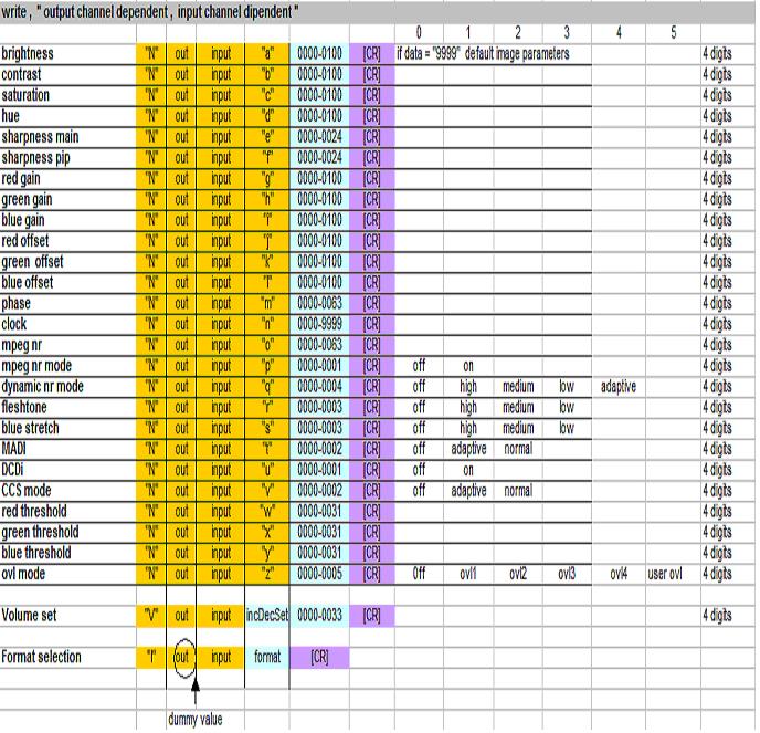
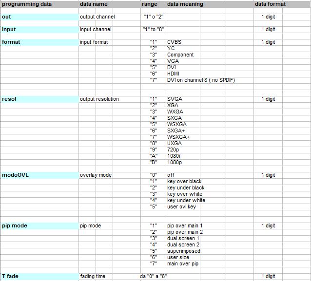
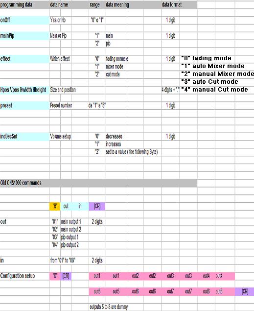
31 8.0 RS232 SERIAL AND ETHERNET COMMANDS All the programming operations described above can be carried out using the remote control or via a remote serial channel: this may be a standard RS232 serial line or an Ethernet LAN that the PC will see as a virtual serial port, programmable using a specific DSManager software driver that can be downloaded free from the site The entire set of commands for driving the DVIPRO1000 and for status acquisition are described below. Elpro makes available complete management software for remote driving of the DVIPRO1000. The serial line is of the three-wire type (TX RX GND) with Baud rate of 9600 baud, no parity and no control of hardware or software flow. The command strings to be sent to the machine and the expected replies are shown in the tables below. The strings consist of ASCII characters and are terminated with the [CR] character
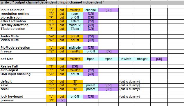
32
33 33 33
34
35 35 35
36 Examples Es1: Selection of input 7 on the main window of output channel 1 The host must send the following sequence: C followed by CR which in hexadecimal corresponds to: D where 1 is the selection of output channel 1 1 is the selection of the main window 7 is the selection of the input on which to switch The DVIPRO1000 replies: ACK (06 hex) if the command has been recognized correctly NACK (15 hex) if transmission errors have occurred BEL (07 hex) when the command has been performed completely Es2: Selection of input 3 on the pip window of output channel 2 The host must send the following sequence: C followed by CR which in hexadecimal corresponds to: D where 2 is the selection of output channel 2 2 is the selection of the pip window 3 is the selection of the input on which to switch The DVIPRO1000 replies: ACK (06 hex) if the command has been recognized correctly NACK (15 hex) if transmission errors have occurred BEL (07 hex) when the command has been performed completely Es3: Selection of SXGA resolution for output channel 2 The host must send the following sequence: R 2 4 followed by CR which in hexadecimal corresponds to: D where 2 is the selection of the output channel and 4 is the selection of the resolution (SXGA = 4)
37 The DVIPRO1000 replies: ACK (06 hex) if the command has been recognized correctly NACK (15 hex) if transmission errors have occurred BEL (07 hex) when the command has been performed completely Es4: Setting of the main window of output channel 2 to size 400x300 with origin in 100,100. The host must send the following sequence: S followed by CR which in hexadecimal corresponds to: E E E E 0D where 2 is the selection of the output channel 1 is the selection of the main window is the X coordinate of the origin of the window is the Y coordinate of the origin of the window is the width of the window in horizontal is the width of the window in vertical The DVIPRO1000 replies: ACK (06 hex) if the command has been recognized correctly NACK (15 hex) if transmission errors have occurred BEL (07 hex) when the command has been performed completely Es5: Setting of the brightness of input 5 for output channel 1 to 50 The host must send the following sequence: N 1 5 a followed by CR which in hexadecimal corresponds to: D where 1 is the selection of the output channel 5 is the selection of the input a is the Brightness parameter 050 is the value to be set The DVIPRO1000 replies: ACK (06 hex) if the command has been recognized correctly NACK (15 hex) if transmission errors have occurred BEL (07 hex) when the command has been performed completely 37 37
38 Es6: recall of preset number 6 The host must send the following sequence: X 0 R 6 followed by CR which in hexadecimal corresponds to: D where R is the selection of the Recall function 6 is the selection of the preset to be recalled The DVIPRO1000 replies: ACK (06 hex) if the command has been recognized correctly NACK (15 hex) if transmission errors have occurred BEL (07 hex) when the command has been performed completely Es7: reading of the Fade time of output channel 1 The host must send the following sequence: R F 1 followed by CR which in hexadecimal corresponds to: D where F is the selection of the Tfade parameter 1 is the selection of output channel concerned The DVIPRO1000 replies: 3 CR which in hexadecimal corresponds to: 33 0D where 3 is the value of the Tfade parameter Es8: reading of the position of the main window of channel 2 The host must send the following sequence: R S 2 1 followed by CR which in hexadecimal corresponds to: D where S is the selection of size data 2 is the selection of the output channel concerned 1 is the selection of the Main window
39 The DVIPRO1000 replies: CR which in hexadecimal corresponds to: E E E E 0D where 0100 is the value of the X origin of the window 0100 is the value of the Y origin of the window 0400 is the value of the width X of the window 0300 is the value of the width Y of the window Es9: Selection of input 7 on the main window of output channel 1 in CNS1000 compatible mode The host must send the following sequence: B followed by CR which in hexadecimal corresponds to: D where 01 is the selection of the main window of the channel 1 07 is the selection of input 7 The DVIPRO1000 replies: ACK (06 hex) if the command has been recognized correctly NACK (15 hex) if transmission errors have occurred BEL (07 hex) when the command has been performed completely Es10: Selection of input 3 on the pip window of output channel 2 in CNS1000 compatible mode The host must send the following sequence: B followed by CR which in hexadecimal corresponds to: D where 04 is the selection of the pip window of channel 2 and 03 is the selection of input 3 The DVIPRO1000 replies: ACK (06 hex) if the command has been recognized correctly NACK (15 hex) if transmission errors have occurred BEL (07 hex) when the command has been performed completely 39 39
40 8.1 Remote command by CNS1000 It is possibile to command the switching of Main and Pip windows of the 2 DVIPRO1000 outputs also by CNS1000 remote console. CNS1000 can be connected to DVIPRO1000 by RS232 or LAN. It is necessary to configure a DVIPRO1000 unit in the console CNS1000 through the NEW UNIT parameters (see CNS1000 Manual). The 8 console inputs correspond to the 8 DVIPRO1000 inputs whereas the 4 outputs correspond to: OUT1 = OUT1 Main Window OUT2 = OUT2 Main Window OUT3 = OUT1 Pip Window OUT4 = OUT2 Pip Window Example: To switch input 5 on OUT1 Main Window press the 5 button as Source and the 1 button as Destination, confirming the switching with TAKE
41 9.0 Firmware Upgrade The firmware contained inside the DVIPRO1000 can be upgraded by RS232. In order to activate this function, turn on the machine and press simultaniously the 1, 2, 7, 8 input keys of the output 2. Connect the PC through the serial line. Use the Elpro Upgrade software, available at the Elpro site. LCD will show the Upgrade state, and when it is finished, you have to turn Off the unit in order to activate the upgrading. WARNING Never turn off the apparatus when the upgrade is on progress!! It is also available a special firmware upgrade for the two Video Output channels boards. This is accomplished through the VGA HDD15 connector, using a special adapter FW1000 to buy apart, and a PC software. Please contact Elpro in order to obtain the documentation and the adapter. WARNING Before to execute any upgrading firmware, is suggested to contact the technical office of ELPRO in order to make the upgrading procedure in the appropriate way
42 10.0 TECHNICAL DATA VIDEO: Inputs: 2 universal CV,Y/C,Component,VGA on HDD15 p.f. 4 universal CV,Y/C,Component,VGA on 3 BNC & 1 HDD15 p.f. 1 universal CV,Y/C,Component,VGA,DVI on 3 BNC & 1 DVI-I 29p.f. 1 universal CV,Y/C,Component,HDMI on 3 BNC and 1 HDMI conn. Input Resolutions: Graphic: from SVGA (800x600) to UXGA (1600x1200) Component: from 525i (PAL) and 625i (NTSC) to 1080p (1920x1080) DVI: Up to 1920x1200 and 1080p 60Hz HDMI: 720p recommended; max. 1080i 60Hz Input Video standard: PAL, SECAM, NTSC Outputs: 2 separate Output type: twin, DVI-D on DVI-I 29 p.f.and VGA+YPbPr on HDD 15 p.f. Output resolutions: Graphic: SVGA (800x600), XGA (1024x768), WXGA (1366x768), SXGA (1280x1024), SXGA+ (1400x1050), WSXGA (1440x900), WSXGA+ (1680x1050), UXGA (1600x1200) YPbPr: 720p, 1080i, 1080p (RGBHV on HDD15p.) Synch.Level: TTL Vertical synch. on output: 60 Hz at any resolution Switching: seamless with Fading, Mixer or Cut Switching Timing: 6 steps from 0 to 3 sec PIP: between 2 inputs UpScale &DownScale: pixel x pixel Pan of both images in X and Y Functions: Preview, Overlay, Titling, Image & color adjustment, DNR, Motion control, VGA Autoadj., Clock & Phase control,
43 AUDIO: Inputs: 8 balanced stereo Outputs: 2 balanced stereo Inputs/Outputs type: balanced with Phoenix Screwtype removable Input coupling: AC Input impedance: 56 KΩ Input level: +9 dbm Max SPDIF out: for HDMI input only VCA on outputs: from MUTE to 100% (33 steps) Frequency response: -1 db from 40 Hz to 20 KHz Crosstalk: 60 db at 5 KHz Distortion: <0.03% at 0 dbm with 10 KÙ load Hum &noise: -75 dbm unweighted Remote command: IR, RS232, LAN Main input: Vac Hz Power consumption: 25 VA Size (WxDxH): 483x210x132 mm Weight: 4,5 Kg Operating temp. range: 0 45 C Safety: according to EN EMC: according to EN and -2 CE Mark 43 43
44 11.0 NOTE This product is guaranteed for 5 years from the date of purchase. If the fault in the product is due to improper use or operations carried out by third parties, the warranty is forfeited. During the warranty period, Elpro will repair the faulty units free of charge. The faulty units must be sent CARRIAGE FREE to the Elpro offices in Turin with a regular accompanying note. The units repaired will be returned CARRIAGE FORWARD to the addressee. Outside the warranty period, Elpro will repair the faulty units EX its Turin offices, charging the cost of the repair to the customer. For any problems during installation of the DVIPRO1000, call the Elpro hot line Tel or info@elprovideolabs.com
DVIPRO100 SWITCHER / HIGH RESOLUTION SCALER & PIP CONTROL
 5 inputs ( 2 HDD15, 1 CVBS, 1 YCbCr or CVBS, 1 Y/C) YCbCr input switchable as CVBS Two PC inputs on HDD15 up to SXGA60 or 1080p RGB or YPbPr analogue output on HDD15 DVI digital output up to SXGA60 or
MDS 100 LINE MULTIPLIER, SCAN CONVERTER AND SWITCHER
 5 INPUTS WITH ASSOCIATED AUDIO 2 SIMULTANEOUS CONVERSIONS: PC/TV AND TV/PC WIDE RANGE OF CORRECTIONS AND ADJUSTMENTS MUTE AUDIO FUNCTION ON BOTH OUTPUTS OSD ON BOTH OUTPUTS MAINTENANCE OF PRESETTINGS POSSIBILITY
SP205+ DUAL 1x5 VIDEO & AUDIO DISTRIBUTION AMPLIFIER
 Two separate x5 video and stereo audio sections Possibility of x5 dual or x0 single configuration Suitable for composite or Y/C signals Suitable for unbalanced stereo audio or mono balanced signals Ed.
TPW300series. CAT5/6 RGBHsVs TRANSCEIVERS
 RGBHsVs Transmitter / Receiver Parallel-settable receivers Jumper type cable loss compensation Suitable for high resolution signals 19" compatible 1 INSTALLATION AND USE OF THE TPW300 SERIES INDEX 1.0
SDZHD Series. 16x16 HD/SD-SDI & AUDIO MATRIX
 Automatic HD/SD-SDI selection External reference switching Selectable switching line Control via keypad, RS232, LAN or CNS1000 remote panel 16 storable presets Balanced audio combined Disabling of equalization
CONVI104 SWITCHER & ANALOG TO SDI CONVERTER CONVI 104-M 15/03/2006
 PAL and NTSC compatible 10-bit sampling Five-stage comb filter EDH generation and insertion Twin SDI output Frame Synch. with optional board (FS104) CONVI 104-M 15/03/2006 1 INSTALLATION AND USE OF THE
GMB101R BLACK BURST & PATTERN GENERATOR GMB101R-M 09/06/08
 4 fixed Black Burst outputs Test output in CV and Y/C Selection of 8 test patterns Output with correlated phase PAL / NTSC 1KHz balanced audio output GMB101R-M 09/06/08 1 1.0 OVERVIEW The GMB101R Black
CP-255ID Multi-Format to DVI Scaler
 CP-255ID Multi-Format to DVI Scaler Operation Manual DISCLAIMERS The information in this manual has been carefully checked and is believed to be accurate. Cypress Technology assumes no responsibility
CSLUX-300 Multi-Format to HDMI Scaler
 CSLUX-300 Multi-Format to HDMI Scaler Operation Manual DISCLAIMERS The information in this manual has been carefully checked and is believed to be accurate. Cypress Technology assumes no responsibility
DIGI-SCAL-5 Installation Guide. Intelix
 DIGI-SCAL-5 Installation Guide Intelix www.intelix.com Important notice: Do not attempt to disassemble or alter the scaler housing. There are no user-serviceable parts inside the unit. Doing so will void
USER MANUAL. VP-437N Presentation Switcher/Scaler MODEL: P/N: Rev 3
 KRAMER ELECTRONICS LTD. USER MANUAL MODEL: VP-437N Presentation Switcher/Scaler P/N: 2900-300156 Rev 3 Contents 1 Introduction 1 2 Getting Started 2 2.1 Achieving the Best Performance 2 2.2 Safety Instructions
CP-255ID CV, SV, VGA and DVI to DVI Scaler / Converter OPERATION MANUAL
 CP-255ID CV, SV, VGA and DVI to DVI Scaler / Converter OPERATION MANUAL DISCLAIMERS The information in this manual has been carefully checked and is believed to be accurate. CYP (UK) Ltd assumes no responsibility
Kramer Electronics, Ltd. USER MANUAL. Model: VP-437xl. Presentation Switcher / Scaler
 Kramer Electronics, Ltd. USER MANUAL Model: VP-437xl Presentation Switcher / Scaler Contents Contents 1 Introduction 1 2 Getting Started 1 2.1 Quick Start 1 3 Overview 3 3.1 Recommendations for Best Performance
10. Sample Windows Control Panel Software(RS-232 version only) x 4A battery
 x 4A battery") (1). Introduction Congratulations on your purchase of the Cypress Video Scaler CSC-200RS. Our professional Video Scaler products have been serving the industry for many years. In addition to Video Scalers,
(1). Introduction Congratulations on your purchase of the Cypress Video Scaler CSC-200RS. Our professional Video Scaler products have been serving the industry for many years. In addition to Video Scalers,
KRAMER ELECTRONICS LTD. USER MANUAL MODEL: VP-436N Presentation Switcher/Scaler. P/N: Rev 1
 KRAMER ELECTRONICS LTD. USER MANUAL MODEL: VP-436N Presentation Switcher/Scaler P/N: 2900-300149 Rev 1 Contents 1 Introduction 1 2 Getting Started 2 2.1 Achieving the Best Performance 2 3 Overview 3
HD Mate Scaler USER MANUAL.
 HD Mate Scaler USER MANUAL www.gefen.com ASKING FOR ASSISTANCE Technical Support: Telephone (818) 772-9100 (800) 545-6900 Fax (818) 772-9120 Technical Support Hours: 8:00 AM to 5:00 PM Monday through Friday
USER MANUAL. VP-441 Presentation Switcher/Scaler MODEL: P/N: Rev 7
 KRAMER ELECTRONICS LTD. USER MANUAL MODEL: VP-441 Presentation Switcher/Scaler P/N: 2900-300040 Rev 7 Contents 1 Introduction 1 2 Getting Started 2 2.1 Achieving the Best Performance 2 2.2 Safety Instructions
KRAMER ELECTRONICS LTD. USER MANUAL MODEL: VP-437N Presentation Switcher/Scaler. P/N: Rev 2
 KRAMER ELECTRONICS LTD. USER MANUAL MODEL: VP-437N Presentation Switcher/Scaler P/N: 2900-300156 Rev 2 Contents 1 Introduction 1 2 Getting Started 2 2.1 Achieving the Best Performance 2 3 Overview 3
USER MANUAL. VP-443 Presentation Switcher/Scaler MODEL: P/N: Rev 5
 KRAMER ELECTRONICS LTD. USER MANUAL MODEL: VP-443 Presentation Switcher/Scaler P/N: 2900-300084 Rev 5 Contents 1 Introduction 1 2 Getting Started 2 2.1 Achieving the Best Performance 2 2.2 Safety Instructions
CSLUX-300I Multi-Format to HDMI Scaler
 CSLUX-300I Multi-Format to HDMI Scaler Operation Manual SAFETY PRECAUTIONS Please read all instructions before attempting to unpack, install or operate this equipment and before connecting the power supply.
CSLUX-300I Multi-Format to HDMI Scaler
 CSLUX-300I Multi-Format to HDMI Scaler Operation Manual DISCLAIMERS The information in this manual has been carefully checked and is believed to be accurate. Cypress Technology assumes no responsibility
USER MANUAL. VP-435 Component / UXGA HDMI Scaler MODEL: P/N: Rev 13
 KRAMER ELECTRONICS LTD. USER MANUAL MODEL: VP-435 Component / UXGA HDMI Scaler P/N: 2900-000262 Rev 13 Contents 1 Introduction 1 2 Getting Started 2 2.1 Achieving the Best Performance 2 2.2 Safety Instructions
CATALOG NUMBER: HK-MX-VGA-X-Y Product Name
 Product Name Screen matrix switcher Describe Matrix switcher is a high-performance intelligent matrix switch device designed for switching of audio and video signals. It switches all audio and video input
SUPERSCALE Multi-Format to HDMI Scaler
 SUPERSCALE Multi-Format to HDMI Scaler Operation Manual DISCLAIMERS The information in this manual has been carefully checked and is believed to be accurate. SPATZ assumes no responsibility for any infringements
Composite to HDMI Scaler
 Composite to HDMI Scaler GTV-COMPSVID-2-HDMIS User Manual Version A2 gefen.com ASKING FOR ASSISTANCE Technical Support: Telephone Email 1-707-283-5900 1-800-472-5555 support@gefen.com Technical Support
CYPRESS TECHNOLOGY CO., LTD.
 (1). Introduction Congratulations on your purchase of the Cypress Video Scaler CSC-200P. Our professional Video Scaler products have been serving the industry for many years. In addition to Video Scalers,
HK-DID-MXA-VGA-X-Y. Product Name. Describe. Application. Characteristic. Product Model. Screen Matrix Switcher
 Product Name Screen Matrix Switcher Describe Matrix switcher is a high-performance intelligent matrix switch device designed for switching of audio and video signals. It switches all audio and video input
User Manual. PTN Electronics. SC121D-TN Scaler Switcher, with Digital Amplifier. Please read this manual carefully before using this product.
 PTN Electronics SC121D-TN Scaler Switcher, with Digital Amplifier User Manual SC Series --- Presentation Scaler Switcher Please read this manual carefully before using this product. l Content table 1.
AVG-SC121D-T. Features
 The AVG-SC121D-T is a full HD scaler switcher with 12 video, 6 audio & 2 MIC inputs. It scales & switches HDMI, VGA, YPbPr, C-Video & S- video to HDBaseT, HDMI & VGA simultaneously, and audio to a 2x20W
VSP 9516S Quick Start
 VIEWSIZE THE WORLD VSP 9516S Quick Start Max 2048 1152@60Hz/2560 816 60Hz input/output resolution User-defined resolution adjustment Picture in picture Audio and video sync Seamless switching between inputs
High-Definition Scaler. GTV-HIDEFS. User Manual
 High-Definition Scaler GTV-HIDEFS User Manual www.gefentv.com Technical Support: Telephone (818) 772-9100 (800) 545-6900 Fax (818) 772-9120 Technical Support Hours: 8:00 AM to 5:00 PM Monday thru Friday.
SC-1080R Multi-Format Switcher & Scaler
 User s Manual SC-1080R Multi-Format Switcher & Scaler Switch and Scale among 8 AV inputs to 3 Simultaneous Outputs Control via Front Panel, IR Remote, RS-232, and IP (WebGUI & Telnet) UMA1247 Rev A CUSTOMER
USER HDSC12. Scaler Switcher with Digital Amplifier
 USER Scaler Switcher with Digital Amplifier Table of Contents 1. Introduction...1 1.1. Introduction to...1 1.2. Package Contents...1 2. Features...2 3. Specification...3 4. Operations of the Control Panel
Video Scaler Pro with RS-232
 Video Scaler Pro with RS-232 - ID# 783 Operation Manual Introduction Features The Video Scaler Pro with RS-232 is designed to convert Composite S-Video and YCbCr signals to a variety of computer and HDTV
VSP 198CVS Quick Start
 VIEWSIZE THE WORLD VSP 198CVS Quick Start Max 2048 1152@60Hz/2560 1152 50Hz input/output resolution User customize output resolution 3G/HD/SD-SDI input Multiple cascade mapping for super resolution DVI
SC-1080D. Multi-format PC/HD Video Scaler
 SC-1080D Multi-format PC/HD Video Scaler SUPPORT & ORDERING INFORMATION For technical support, Call 714-641-6607 or fax 714-641-6698 Order by phone: toll-free in the U.S. 800-959-6439 Web site: www.hallresearch.com
Installation Guide SY-MS51. and SY-MS51-AP. Scaling Presentation Switcher
 Installation Guide SY-MS51 and SY-MS51-AP Scaling Presentation Switcher 3 HDMI, 2 VGA (RGBHV, YPbPr or Composite Video) inputs Simultaneous HDMI & HDBT outputs SY Electronics Ltd, 7 Worrall Street, Salford,
HD Leeza. Quick Setup Guide
 Page 1 of 15 Model KD-HD1080P Key Digital Video Processor Quick Setup Guide Have a question or a technical issue with your set-up? Call the Key Digital Hotline at: 866-439-8988 or 203-798-7187 E-mail the
VSP 168HD Quick Start
 VSP 168HD Quick Start Support 10Gbps of transmission rate Support HDBaseT protocols and standards Support USB upgrade Max 2048 1152@60Hz/2560 816 60Hz input/output resolution Support custom output resolution
USER MANUAL. VP-422 HDMI to PC Scaler MODEL: P/N: Rev 5
 KRAMER ELECTRONICS LTD. USER MANUAL MODEL: VP-422 HDMI to PC Scaler P/N: 2900-000580 Rev 5 Contents 1 Introduction 1 2 Getting Started 2 2.1 Achieving the Best Performance 2 2.2 Safety Instructions 3
SY-MS121 SY-MS121-AP
 Installation Guide SY-MS121 and SY-MS121-AP Presentation Switcher with Multi-Format Inputs and Outputs 4 HDMI, 4 VGA, 1 Component video, 2 Composite video & 1 S-video inputs Simultaneous HDMI, VGA & HDBaseT
DVI/PC/HD to DVI/PC Scaler - ID# 15320
 DVI/PC/HD to DVI/PC Scaler - ID# 15320 Operation Manual Introduction This DVI/PC/HD to DVI/PC Scaler is capable of scaling and sourceswitching from PC (VGA), Component Video (SD/HD) and DVI input signals
USER MANUAL. VP-426 HDMI-PC Scaler MODEL: P/N: Rev 4.
 USER MANUAL MODEL: VP-426 HDMI-PC Scaler P/N: 2900-300277 Rev 4 www.kramerav.com Contents 1 Introduction 1 2 Getting Started 2 2.1 Achieving the Best Performance 2 2.2 Safety Instructions 2 2.3 Recycling
G3 NET 2K USER MANUAL
 G3 NET 2K USER MANUAL Article No: RGB-RD-UM-G3 NET 2K E001 Revision No: V1.0 CONTENTS CONTENTS... 1 Declarations... 3 FCC/Warranty... 3 Operators Safety Summary... 4 Installation Safety Summary... 4 Chapter
Multi-format to HDMI scaler ID#15107
 Multi-format to HDMI scaler ID#15107 Operation Manual Introduction The Digital Video Scaler has CV, SV, HD, Composite, PC, HDMI and SDI inputs and can scale the signal into HDMI, VGA with audio output
CONVI104R. CV to SDI Converter CONVI 104R-M 09/04/2005
 PAL and NTSC compatible 10-bit ADL sampling Frame sync on optional board Loop type ref. Input Five-line adaptive comb filter EDH generation and insertion Crystal Jitter filter Double SDI output To be fitted
Intelligent Security and Fire Ltd
 User Manual Product ranges covered by this manual Vi-P14 Vi-P14A Document Reference Date Firmware Vi-Q4C1 Viq601a.doc 26/11/2009 From Viq001a21 Videoswitch Telephone 01252-851510 Ocean House, Redfields
Bel 2120B. Analogue/AES/SDI Shuffler. User s Guide Version /05/04
 Bel 2120B Analogue/AES/SDI Shuffler User s Guide Version 1.0 06/05/04 BEL (Digital Audio) Ltd. has made every effort to ensure the accuracy of information contained within this document which is nevertheless
VENUS X1PRO-E Quick Start
 VENUS X1PRO-E Quick Start 4K input support in DP, HDMI and Dual Link DVI Support 8K x 1K, 4K x 2K Seamless Splicing EDID management Modular 2K input: Three slots for 2K input options 2K-2K and/or 4K-2K
USER MANUAL. Kramer Electronics, Ltd. Models: VP-719xl, Presentation Switcher / Scaler. VP-720xl, Presentation Switcher / Scaler
 Kramer Electronics, Ltd. USER MANUAL Models: VP-719xl, Presentation Switcher / Scaler VP-720xl, Presentation Switcher / Scaler VP-724xl, Presentation Switcher / Scaler Contents Contents 1 Introduction
Instruction Manual 1T-AVPC-HDMI HDMI Video Scaler
 99 Washington Street Melrose, MA 02176 Phone 781-665-1400 Toll Free 1-800-517-8431 Visit us at www.testequipmentdepot.com Instruction Manual 1T-AVPC-HDMI HDMI Video Scaler Table of Contents 1.0 Introduction
KD-MSVA4X4. 4 Inputs to 4 Outputs Component Video with Audio Matrix Switcher. Operating Instructions
 KD-MSVA4X4 4 Inputs to 4 Outputs onent Video with Audio Matrix Switcher Operating Instructions Key Digital FatBoy Series KD-MSVA4x4 is a Video/Audio Matrix Switcher capable of separate switching of 4 onent
High Definition 1080p Scaler
 High Definition 1080p Scaler GTBHD1080PS GTBHD1080PSBLK User Manual INTRODUCTION Congratulations on your purchase of the GefenToolBox High Definition 1080p Scaler. Your complete satisfaction is very important
EL-5500 Advanced HDMI/VGA Presentation Switch OPERATION MANUAL
 EL-5500 Advanced HDMI/VGA Presentation Switch OPERATION MANUAL DISCLAIMERS The information in this manual has been carefully checked and is believed to be accurate. CYP (UK) Ltd assumes no responsibility
Kramer Electronics, Ltd. USER MANUAL. Model: VP-724DS. Seamless Switcher / Scaler
 Kramer Electronics, Ltd. USER MANUAL Model: VP-724DS Seamless Switcher / Scaler Contents Contents 1 Introduction 1 2 Getting Started 1 3 Overview 2 4 Your VP-724DS Seamless Switcher / Scaler 3 5 Connecting
Kramer Electronics, Ltd. USER MANUAL. Models: VP-720DS, Seamless Switcher / Scaler VP-723DS, Seamless Switcher / Scaler
 Kramer Electronics, Ltd. USER MANUAL Models: VP-720DS, Seamless Switcher / Scaler VP-723DS, Seamless Switcher / Scaler Contents Contents 1 Introduction 1 2 Getting Started 1 3 Overview 1 4 Your Seamless
ESI VLS-2000 Video Line Scaler
 ESI VLS-2000 Video Line Scaler Operating Manual Version 1.2 October 3, 2003 ESI VLS-2000 Video Line Scaler Operating Manual Page 1 TABLE OF CONTENTS 1. INTRODUCTION...4 2. INSTALLATION AND SETUP...5 2.1.Connections...5
OPERATING GUIDE. HIGHlite 660 series. High Brightness Digital Video Projector 16:9 widescreen display. Rev A June A
 OPERATING GUIDE HIGHlite 660 series High Brightness Digital Video Projector 16:9 widescreen display 111-9714A Digital Projection HIGHlite 660 series CONTENTS Operating Guide CONTENTS About this Guide...
LedSync820C LED Video Processor USER S MANUAL
 LedSync820C LED Video Processor USER S MANUAL TABLE OF CONTENTS I. Safety precautions ----------------------------------------------------------------- 3 II. Connections of hardware 1.Rear view ------------------------------------------------------------
MODEL SC1080-H UMA1165 Rev A
 Video to PC/HDTV Switching Scaler Composite, S-Video, Component, PC and HDMI AV Inputs HDMI AV Output with Separate Digital Audio Output Front Panel, IR Remote, & RS-232 Serial Control MODEL SC1080-H UMA1165
PC/HDTV to PC/HDTV converter (CP-251F)
") PC/HDTV to PC/HDTV converter (CP-251F) Operation Manual This Converter has been especially modified to also accept RGsB Sync on Green Operation Controls and Functions Front Panel 1. Reset/ and +- The and
PC/HDTV to PC/HDTV converter (CP-251F) Operation Manual This Converter has been especially modified to also accept RGsB Sync on Green Operation Controls and Functions Front Panel 1. Reset/ and +- The and
HDMI 1 HDMI 2 HDMI 3 HDMI
 Mode HDMI 1 HDMI 2 HDMI 3 HDMI 4 Format Menu Up Enter IR Dual Switcher Power Embed L/R In HDMI 1 HDMI 2 HDMI 3 HDMI 4 VGA YPbPr AV Down Esc MFP72 User Manual Thank you for purchasing this product. For
CONTENT Product Introduction... 2 Packing Configuration...3 Hardware Orientation... 4 Front Panel... 4 Back Panel... 6 Using Your Product... 7 Content
 VENUS X1PRO Quick Start 4K input support in DP, HDMI and DVI Input standard 2K formats Scale and switch seamlessly between 2K and 4K inputs Output to any format 2K or 4K EDID management on board HDCP 2.0
P-2 Installing the monitor (continued) Carry out as necessary
 Carry out as necessary") P-2 Installing the monitor (continued) Carry out as necessary Using the monitor without the bezel MDT552S satisfies the UL requirements as long as it is used with the bezel attached. When using the monitor
P-2 Installing the monitor (continued) Carry out as necessary Using the monitor without the bezel MDT552S satisfies the UL requirements as long as it is used with the bezel attached. When using the monitor
DVI-3580a. 4K MultiViewer Switcher / Scaler. Quick Start Guide. Introduction
 Quick Start Guide 4K MultiViewer Switcher / Scaler Introduction Presentation Powerhouse The is a high-performance 4K MultiViewer Switcher / Scaler. This unit is an ideal solution for system designers and
User Manual. PC / HD Scaler. with advanced video processing. VGA to Component Video Component Video to VGA VGA to VGA Component to Component
 User Manual PC / HD Scaler with advanced video processing VGA to Component Video Component Video to VGA VGA to VGA Component to Component Model 1366 WARNINGS Read these instructions before installing or
isync HD & isync Pro Quick Reference Guide isync HD isync Pro Digital Video Processor and Video/Audio Switcher
 isync HD & isync Pro Digital Video Processor and Video/Audio Switcher Quick Reference Guide isync HD Key Digital, led by digital video pioneer Mike Tsinberg, develops and manufactures high quality, cutting-edge
FLEX Series. Small-Scale Routing Switcher. KEY FEATURES AND BENEFITS Frame and signal. Flexible control. Communication and control.
 CE FLEX series features high performance and compact structure. Mix of different signal formats (CVBS, AUDIO, 3G/HD/SD-SDI, DVB-ASI, HDMI and VGA) is allowed in a single frame. Switching sizes can be customized
SC-HD-2A HDMI Scaler & Audio Embedder / Extractor
 User s Manual SC-HD-2A HDMI Scaler & Audio Embedder / Extractor Scale HDMI or DVI video Embed Digital or Analog Audio into HDMI output Extract (De-embed) Digital and Analog Audio from HDMI input UMA1246
INSTRUCTION MANUAL. 19 HD Widescreen Water Resistant Television VSPA19LCD-AE1B VSPA19LCD-AE1M VSPA19LCD-AE1W. Model No. FINGER TOUCH TECHNOLOGY RATED
 INSTRUCTION MANUAL 19 HD Widescreen Water Resistant Television VSPA19LCD-AE1B Model No. VSPA19LCD-AE1M VSPA19LCD-AE1W FINGER TOUCH TECHNOLOGY IMPORTANT: Please read these instructions before installing
Front and Rear Panel Remote Control Connecting to a Television...4. Connecting to an Audio System...5
 Table of Contents Front and Rear Panel... 1 Remote Control...... 2 Connecting to a Television...4 Connecting to an Audio System...5 Connecting to a DVD Recorder or VCR... 6 First Time Installation... 7
AZ DISPLAYS, INC. COMPLETE LCD SOLUTIONS SPECIFICATIONS FOR 15.0 OPEN FRAME MONITOR
 AZ DISPLAYS, INC. COMPLETE LCD SOLUTIONS SPECIFICATIONS FOR 15.0 OPEN FRAME MONITOR PART NUMBER: AOM150X03 SERIES DATE: SEPT 04, 2008 1. Introduction: 1.1 About the Product AOM150Xxx 15.0 Open Frame Monitor
DVI Digital scaler with ultra high bandwidth ID#442
 DVI Digital scaler with ultra high bandwidth ID#442 Operation Manual Introduction Congratulations on your purchase of the DVI Digital scaler with ultra high bandwidth. Please read this to become familiar
SET TOP BOX MODEL: GDB01SFV1 USER MANUAL
 SET TOP BOX MODEL: USER MANUAL 1 2 3 4 5 6 7 8 Welcome Your Set Top Box 2.1 In The Box 2.2 Front View 2.3 Rear View Quick Setup 3.1 TV Connection 3.2 Recording from the set top box 3.3 Record one channel
AVMU2-BHD+/3G Audio monitoring Unit
 AVMU2-BHD+/3G Audio monitoring Unit Handbook Television Systems Limited. Vanwall Road, Maidenhead, Berkshire, SL6 4UB Telephone +44 (0)1628 676200, FAX +44 (0)1628 676299 AVMU2-BHD+/3G 1 ISSUE 3 SAFETY
LCD VALUE SERIES (32 inches)
") LCD VALUE SERIES (32 inches) http://www.orionimages.com All contents of this document may change without prior notice, and actual product appearance may differ from that depicted herein 1. SAFETY INSTRUCTION
LCD VALUE SERIES (32 inches) http://www.orionimages.com All contents of this document may change without prior notice, and actual product appearance may differ from that depicted herein 1. SAFETY INSTRUCTION
Audio / Video Scaler Pro EXT-GSCALER-PRO User Manual
 Audio / Video Scaler Pro EXT-GSCALER-PRO User Manual www.gefen.com Technical Support: Telephone (818) 772-9100 (800) 545-6900 Fax (818) 772-9120 Technical Support Hours: 8:00 AM to 5:00 PM Monday thru
DiD. LCD Video Monitor & Video Wall Universal User Manual. Digital Information Display
 LCD Video Monitor & Video Wall Universal User Manual DiD Digital Information Display Video Monitor Models M82S1/M70S1/M65S1/M55S1/M46S1/M40S1/M32S1/M24S1/M19S2/M19S1 Video Wall Models PD55N3/PD46N4/PD46N3/PD46N2/PD40N2
User Manual. Model 1365 Video Scaler
 User Manual Model 1365 Video Scaler Model 1365 PC/HD Video Converter Table Of Contents 1.0 Introduction........................3 2.0 Specifications....................... 4 3.0 Checking Package Contents................5
Video to 1080i High Definition RGB Component Converter/Scaler ID# 499
 Video to 1080i High Definition RGB Component Converter/Scaler ID# 499 Operation Manual Introduction The Video to 1080i High Definition RGB Component Converter/Scaler is designed to convert Composite, S-Video,
User Guide. Video to VGA/HD Converter/Scaler DVI-3420a. Video to DVI Converter/Scaler DVI-3410a
 User Guide Video to VGA/HD Converter/Scaler DVI-3420a Video to DVI Converter/Scaler DVI-3410a TABLE OF CONTENTS SECTION PAGE PRODUCT SAFETY... 1 PRODUCT LIABILITY.... 1 1.0 INTRODUCTION.... 2 2.0 SPECIFICATIONS....
ACUBRITE 23 SS. Manual. Stainless Steel Chassis 23" LCD Display. Content
 ACUBRITE 23 SS Stainless Steel Chassis 23" LCD Display Manual Introduction... 2 Hardware Installation... 2 The Display Timing... 5 The Display Outline Dimensions... 6 The Display Controls... 7 The Screen
USER MANUAL. VP-425 PC / Component to HDMI Scaler MODEL: P/N: Rev 3
 KRAMER ELECTRONICS LTD. USER MANUAL MODEL: VP-425 PC / Component to HDMI Scaler P/N: 2900-300111 Rev 3 Contents 1 Introduction 1 2 Getting Started 2 2.1 Achieving the Best Performance 2 2.2 Safety Instructions
TFT LCD MONITOR USER MANUAL. L80AP and L101AP
 TFT LCD MONITOR USER MANUAL L80AP - 8.0 and L101AP - 10.1 Table Of Contents Table of contents/ Warning.... 2 Precautions...3 About this user manual and products / Items included in the delivery..... 4
and HDCP 2.2 supported Digital Multi Switcher MSD-702UHD
 RoHS 4K@60 and HDCP 2.2 supported Multi Switcher Ver.1.2.0 (180713) The IDK is a high-performance digital multi switcher with a scan converter and up to 7 inputs and 2 outputs. For video input, 7 digital
VENUS X1 USER MANUAL
 VENUS X1 USER MANUAL Article No: RGB-RD-UM-X1 E001 Revision No: V1.5 CONTENTS CONTENTS... 1 Declarations... 3 FCC/Warranty... 3 Operators Safety Summary... 4 Installation Safety Summary... 4 Chapter 1
Video Wall Display User s Manual
 Video Wall Display User s Manual Manual Version TL46-55H1.1 Our Full Product Range Page 1 Safety Instructions Please handle the display with extreme care, significant impact will damage the LCD panel.
RMS 8424S Quick Start
 VIEWSIZE THE WORLD RMS 8424S Quick Start Standard 4 unit rack mount size 8 inch LCD 2 1024 3 (RGB) 600 16:9 / 4:3 adjustable SDI/HDMI embedded audio output via 3.5mm earphone socket Support SDI/DVI audio
Marshall Electronics. Pro A/V Communications VMV-402-SH. 3G/HD/SD-SDI Quad-viewer/Switcher with Audio Meter Display. User Manual.
 Marshall Electronics Pro A/V Communications VMV-402-SH 3G/HD/SD-SDI Quad-viewer/Switcher with Audio Meter Display User Manual Table of Contents 1. Introduction... 3 2. Features... 3 3. Package Contents...
CP 3072S Quick Start
 VIEWSIZE THE WORLD CP 3072S Quick Start 4 channels, 16 signal sources Preview and program outputs separately PIP between any two inputs Seamless switching between any two channels Seamless switching between
CSC-5500 Multi Input Scaler
 CSC-5500 Multi Input Scaler Operation Manual DISCLAIMERS The information in this manual has been carefully checked and is believed to be accurate. Cypress Technology assumes no responsibility for any
VGA To DVI Scaler PLUS
 VGA To DVI Scaler PLUS USER MANUAL www.gefen.com ASKING FOR ASSISTANCE Technical Support: Telephone (818) 772-9100 (800) 545-6900 Fax (818) 772-9120 Technical Support Hours: 8:00 AM to 5:00 PM Monday through
AC334A. VGA-Video Ultimate BLACK BOX Remote Control. Back Panel View. Side View MOUSE DC IN BLACK BOX ZOOM/FREEZE POWER
 AC334A BLACK BOX 724-746-5500 VGA-Video Ultimate BLACK BOX 724-746-5500 Zoom Position PAL ZOOM/FREEZE POWER FREEZE ZOOM NTSC/PAL SIZE RESET POWER Size Power Remote Control DC IN MOUSE MIC IN AUDIO OUT
Winmate Communication INC.
 20.1 Military Grade Display Model: R20L100-RKA2ML User s Manual Winmate Communication INC. May, 2011 1 IMPORTANT SAFETY INSTRUCTIONS Please read these instructions carefully before using the product and
ET-YFB100G S P E C F I L E. Digital Interface Box. As of December Specifications and appearance are subject to change without notice.
 Product Number : Product Name :. Specifications and appearance are subject to change without notice. 1 / 8 Description This digital interface box is designed for use with an applicable Panasonic projector.
17 19 PROFESSIONAL LCD COLOUR MONITOR ART
 17 19 PROFESSIONAL LCD COLOUR MONITOR ART. 41657-41659 Via Don Arrigoni, 5 24020 Rovetta S. Lorenzo (Bergamo) http://www.comelit.eu e-mail:export.department@comelit.it WARNING: TO REDUCE THE RISK OF FIRE
Video Series. HCS-4311M Professional Mixed Matrix for Conference 8.2. HCS-3313C High Quality Speed Dome Camera (ceiling) 8.5
 8.5") Video Video Series Series Video Tracking System 8.2 HCS-4311M Professional Mixed Matrix for Conference 8.2 HCS-3313C High Quality Speed Dome Camera (ceiling) 8.5 HCS-3313D High Quality Speed Dome Camera
Video Video Series Series Video Tracking System 8.2 HCS-4311M Professional Mixed Matrix for Conference 8.2 HCS-3313C High Quality Speed Dome Camera (ceiling) 8.5 HCS-3313D High Quality Speed Dome Camera
USER MANUAL. VP-501N UXGA Scan Converter MODEL: P/N: Rev 5
 KRAMER ELECTRONICS LTD. USER MANUAL MODEL: VP-501N UXGA Scan Converter P/N: 2900-300183 Rev 5 Contents 1 Introduction 1 2 Getting Started 2 2.1 Achieving the Best Performance 2 2.2 Safety Instructions
28 & 32 & 40 & 55 & 65 & 84-INCH TFT-LCD 4K MONITOR
 28 & 32 & 40 & 55 & 65 & 84-INCH TFT-LCD 4K MONITOR INSTRUCTION MANUAL Please read this manual thoroughly before use, and keep it handy for future reference. TABLE OF CONTENTS 1, General information...
USER MANUAL. 27 Full HD Widescreen LED Monitor L27ADS
 USER MANUAL 27 Full HD Widescreen LED Monitor L27ADS TABLE OF CONTENTS 1 Getting Started 2 Control Panel/ Back Panel 3 On Screen Display 4 Technical Specs 5 Care & Maintenance 6 Troubleshooting 7 Safety