Operating Manual P.01. Outperform. Outlast. Operating Manual YACHT AIRCRAFT HOTEL
|
|
|
- Mariah Willis
- 5 years ago
- Views:
Transcription

1 P.01 Outperform. Outlast. YACHT AIRCRAFT HOTEL
2 P.02 CONTENTS Outperform. Outlast. C.01 INTRODUCTION C.02 FEATURES C.03 PRODUCT DIMENSIONS C.04 INITIAL PRODUCT SET-UP Set-up P.06 Images P.07 - P.08 Electric connector P.09 C.05 PRODUCT INTEGRATION Product Integration / Covering P.10 Sample images P.11 - P.13 Complete covering P.14 C.06 PRODUCT CONTROL Programming the remote control (S435) P.15 Resetting the receiver P.16 Connection to a room control system P.16 C.07 TROUBLE SHOOTING C.08 LEGAL NOTICE
3 C.01: P.03 INTRODUCTION Outperform. Outlast. Intended Use The product swivels out of LCD and plasma TV equipment. All company names and product names are trademarks of the corresponding owner. All rights reserved. The scope of supply can vary depending on the product and the range of fixtures and fittings. Please check that the product supplied is complete and inform us within seven days of delivery if the scope of supply is not complete. Safety and Hazards Recommendations Please read this chapter carefully and follow all of the instructions provided. In this way you are able to guarantee the reliable operation and a long lifespan for your lift system. Keep the operating manual in a safe place. In the event of damage which is the result of non compliance with this operating manual, all claims pertaining to the guarantee are null and void. We generally accept no responsibility for secondary damage. We accept no responsibility for damage to objects or persons which is caused by the inappropriate use of the product or through ignoring the safety instructions. In such cases, all claims pertaining to the guarantee are null and void. For safety reasons, the unauthorized conversion and/or changing of the product is not permitted. Do not dismantle this product. This product is not a toy and does not belong in the hands of children. Do not allow the product to become damp or wet. Do not leave the packaging material lying around as children may choke if they swallow it. The product will be damaged if it is dropped, even from a low height. Before using the product for the first time, please check that the free raising and lowering of the Flatlift including the mounted TV equipment is possible and ensure a collision-free run. For legal reasons and insurance purposes, your Flatlift is equipped with an automatic safety device. This means that the button which controls the raising and lowering must be pressed down all the time. The system stops and remains in the same position as soon as you let go of the button. Quality In the choice of our components, our primary focus was on ensuring a high level of functionality, straightforward use, safety and reliability. We would like to thank you for the trust you have placed in our Flatlift brand products. We can help you with your installation through providing individual customer care.
4 5 years full service Outperform. Outlast. C.02: P.04 PRODUCT FEATURES FEATURES Features: Installion dimensions Flatlift W=1645mm D=1050mm H=200mm opening rate 1,2 /sek Angle of aperture 95 Max. TV weight incl. cover 160Kg Max. TV size 50 (inch) (max. TV size in mm: W=1345mm, H=800mm, D=160mm) Power-on time 15%/h Low noise level < 45 db Environmental temperature from +5 C bis 40 C 4x flexible adjustable assambly brackets Remote control 433,63MHz Connection to room control system possible TV switch-off if closed BUY NOW Scope of supply: Flatlift Slimline 50 Control box 24V power supply unit Remote control LIFETIME Repaircost limit GUARANTY

5 C.03: P.05 PRODUCT DIMENSIONS DIMENSIONS Schnitt Cut a-a a-a a a
6 C.04: P.06 INITIAL PRODUCT SET UP Outperform. Outlast. Initial setting / installation 1. Unpack your Slimline Plasma ceiling TV lift and place the Slimline on a level surface. 2. Align the 4 ceiling mounting brackets with the section as shown on page 07, image 1, No. 2 in a way that these fit your project optimally. You can displace the mounting brackets simply as you wish until these have reached the ideal position. Afterwards, please screw the brackets to the section by means of the screws provided (DIN 912 M8, SW6) using an Allen wrench. 3. Now, transfer the dimension of the hole centre distance of the mounting brackets to your prepared ceiling recess (S.07, image 1, No. 1). Use a drill (d = 8mm) to drill into your ceiling material. In case the Slimline ceiling lift is to be installed on a yacht with metal/aluminium ceiling, we recommend drilling a hole having the size suitable for a screw M8 (recommended drill/core hole diameter = 6.8mm). In case of concrete ceiling installation please use mounting anchors approved for being used with cracked respectively non-cracked concrete. We recommend using mounting anchors of the company Fischer. In case the installation is implemented with a wooden ceiling, you may install the Slimline lift to the wooden ceiling using wood screws (DIN 512, d = 8mm). The anchor respectively screw length should be at least 80mm for concrete or wooden ceiling installations. 4. Please attach your Slimline to the ceiling using the 4 mounting brackets (page 07, image 1, No. 1). 5. Now, align the 2 vertical supports in the Slimline flap with the VESA attachment dimension of your plasma / LCD TV, as shown in figure 2. In order to be able to move the supports, you have to loosen the DIN 912 screws using an Allen wrench (page 08, image 2, No. 3, SW 4). In doing so, the supports can be displaced horizontally to the dimension of the hole centre distance of the TV correspondingly. Once you have reached to desired distance, retighten the screws. Now, you transfer the hole centre distance from the X axis to the Slimline flap. Please observe that the holes of the X axis have been transferred to the section in a centred manner. 6. Now, you can transfer the coordinates of the Y axis of the TV mounting holes to the Slimline flap. During this step you will have the opportunity to align the TV upwards or downwards as the customer desires. 7. After you transferred all hole coordinates to the Slimline flap, you can centre punch the same now and drill the holes using a drill corresponding to the size of the screws (see page 08, image 3, No. 4). As there is no applicable standard for these mounting screws, we are not able to recommend an exact drilling diameter. The screws for wall-mounted TV sets may vary between M6 and M10 in dependency on the TV model. Please consult the Flatlift distribution department prior to ordering the product respectively procure the suitable screws with the local screw dealer.


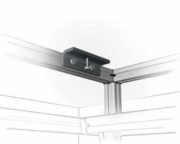
7 C.04: P.07 INITIAL PRODUKT PRODUKT SET UP SET U Image 1 2 1


8 C.04: P.08 INITIAL PRODUCT PRODUKT SET UP SET U Image 2 Image 3 3 4
. 3.")
 and the 24V mains adaptor (image 6, No. 10) to the mains supply. 5. Now, please store the control box and the mains adaptor in the suspended ceiling or in a free area of the Slimline.")
9 C.04: P.09 INITIAL PRODUKT PRODUKT SET UP SET U Image 4 Image 5 Image Minus (-) (+) Plus Electrical connection: 1.Connect the motors to the control box (image 4, No. 5). Now, you may connect the motors to the control box. There is no connection sequence to be observed. 2. Connect the limit switch to the control box (image 5, No. 6). 3. Connect the 24V mains adaptor (image 6, No. 7) to the control box (image 5, No. 8). Please observe the polarity (image 6, No. 7). 4. Connect the control box (image 4, No. 9) and the 24V mains adaptor (image 6, No. 10) to the mains supply. 5. Now, please store the control box and the mains adaptor in the suspended ceiling or in a free area of the Slimline. Please consider planning a revision recess (see chapter 5, page 10). 6. Open and close your Flatllift Slimline once without the TV. In doing so, please observe a free pivoting area, so that the Flatlift Slimline does not make contact with any obstructions. 7. Due to insurance purposes, your Flatlift Slimline is equipped with an automatic safety device. This means that the button for opening and closing the system has to be pressed permanently. As soon as the button is no longer pressed, the Slimline system stops.
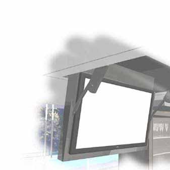
10 C.05: P.010 PRODUCT INTEGRATION INTEGRATION Product integration / cover flap lining: The Slimline cover flap may be lined in different variations. It is important to design a revision aperture allowing you to enter into the interior or the Slimline ceiling lift in case the Slimline has a failure. This section is to explain how the flap can be lined best. 1. Page 11, image 2, No. 1. Here, the flap of the Slimline ceiling lift is lined with the help of a 12mm MDF board. In this example our integrator used the product Scotch 3M Dual Lock. Scotch 3M Dual Lock is a high performance adhesive tape (similar to hook-and-loop adhesive tape). The design of this adhesive tape allows for very high holding forces. For this, please attach the 3M tape to the Slimline flap over a large area. Please observe that the flap of the Slimline lift has to be closed while attaching the tape. After having attached the adhesive tape to the flap, please remove the adhesive film and press the cover flap lining against the Slimline flap from the bottom. Please observe that the flap has to be aligned with the ceiling recess in order to obtain a uniform image. 2. Page 12, image 3. Here, the cover lining is screwed directly to the Slimline flap. In the grooves of the aluminium section there are 4 sliding blocks with holes of d = M6, suitable for counter-sunk screws DIN Depending on the design of the ceiling you may fill respectively cover these DIN 7991 counter-sunk screws with the actual ceiling lining material, so that the same are no longer visible. According to our experience this is one of the most commonly used lining variant, which furthermore may be implemented very easily. 3. On page 12, image 4 the cover lining is directly screwed through the flap of the Slimline TV lift. For this, align the cover plate accordingly and drill 4-8 times directly through the centre of the aluminium section, as shown on page 12, figure 4, No. 2. Afterwards, you can attach the cover plate using screws of an appropriate length. (In our case study we use 12mm MDF wood. Thus, in accordance with the thickness of the aluminium section (40mm) we use at least 45-50mm long wooden Spax screws in order to obtain a corresponding attachment stability. 4. On page 13, image 5, No. 3 you see how the flap solution is implemented at the rear end of the Slimline. The cover plate should project over the pivot axle of the flap by approximately mm and should be equipped with a mitre of approximately 45 at the end. The room ceiling lining in the recess area for the Slimline should be mitred with 45 as well. Thus, the cover flap can pivot freely at a minimum clearance. Furthermore, this solution has the advantage of the view into the rear part of the Slimline lift being prevented in case the Slimline is pivoted to the full extent. 5. You are free to encase your Slimline to a further extent, such as the Slimline flap with TV integrati on, respectively the interior of the Slimline, see page 14, image 6.1 and 6.2. However, in doing so you should observe a proper movement being provided for at any time.


11 C.05: P.011 PRODUCT INTEGRATION INTEGRATION Image 1 1 Image 2


12 C.05: P.012 PRODUCT INTEGRATION INTEGRATION Image 3 Image 4 2


13 C.05: P.013 PRODUCT INTEGRATION INTEGRATION Image


14 C.05: P.014 PRODUCT INTEGRATION INTEGRATION Complete Covering Image 6.1 Image 6.2
: You can also get additional remote controllers for")
 To access the programming key, remove the cover (image 1, no. 1) on the receiver.")
 Holding the programming key down, press the first key on the remote control at the same time (image 2, no. 5).")
 To store a second channel, repeat the procedure starting at step 2 using the second key on the remote control")
15 C.06: P.015 PRODUCT CONTROL CONTROL Programming the remote control (S435): You can also get additional remote controllers for your Flatlift system (optional extra). As the controllers are coded, you have to programme them. 1) To access the programming key, remove the cover (image 1, no. 1) on the receiver. 2) Press down the left hand key (image 1, no. 2). After this, an LED (image 1, no. 3) will then flash slowly. 3) Holding the programming key down, press the first key on the remote control at the same time (image 2, no. 5). On recognising the remote control, the LED (image 1 no. 3) starts to flash rapidly. 4) Release both of the keys. 5) To store a second channel, repeat the procedure starting at step 2 using the second key on the remote control (image 2, no. 6). If your remote control has been successfully recorded, you should hear a soft click in the receiver when you press down the key on the controller Image Image 2


 Press down both of the programming keys (image 3, no. 2 + 4) until the LED (image 3, no.")
 Now re-enter your remote control (refer to P.15).")
: Contact 1: Contact 2: Contact 3: Contact 4: Contact 5: Contact 6: Contact 7: Contact 8:")

16 C.06: P.016 PRODUCT CONTROL CONTROL Resetting the receiver: It may sometimes occur that the transmitting codes stored in the receiver are lost. In this case, the receiver must be cleared and re-programmed. 1) To access the programming key, remove the cover (image 1, no. 1) on the receiver. 2) Press down both of the programming keys (image 3, no ) until the LED (image 3, no. 3) rapidly flashes. This is the signal that the memory has been successfully cleared. 3) Now re-enter your remote control (refer to P.15) Image 3 1 Image 4 Receiver contacts (Img.4): Contact 1: Contact 2: Contact 3: Contact 4: Contact 5: Contact 6: Contact 7: Contact 8: Contact 9: Contact 10: unused open outlet open inlet close outlet close inlet unused power supply +12V power supply 0V unused add on antenna Anschluss an eine Raumsteuerung: To assable your Flatlift Slimline to the room control system, disconnect the contacts 2-5 (Abb.4). Connect these cables with the relay outputs of your room control system (Img.5). The relays of the room control system should be open as the case of may be close for 120 sec. Image 5
17 C.07: P.017 TROUBLE SHOOTING SHOOTING Trouble shooting: If your Flatlift is not working properly, please make sure you check the following things: The Flatlift won t move up or down Is the power cord attached to the control box? S Check the main connection Are all of the plugs properly connected to the control box? (NOTE: plugs which are not connected properly can damage the system) S Check all of the connections Is there any evidence of damage to the cables, the control box, the remote control or the Flatlift? S Damaged components must be exchanged. Please contact us.. The Flatlift has stopped and will only move in the wrong direction. S Is your Flatlift fully extended already? S Is the TV too heavy? S Remote control command possibly deleted! Have you, in error, attached a TV to your Flatlift which is too heavy? S Take the TV off the Flatlift and now see if the Flatlift works. Is the remote control working? S Change the battery in the remote control if necessary. Is the receiver receiving the signals? S When activating the remote control, the relay should click on both channels. (If the receiver does not click, please delete the channels and re-set them. Refer to page 16) The lifting mechanism jerks or stutters? S Please check as to whether another frequency source is also transmitting at 433 Mhz in your house (possible sources of problems: garage door opener, baby phone, alarm system or intercom). With a frequency jammer you will have to change over to a frequency of 868 Mhz! A free changeover from 433 Mhz to 868 Mhz is only possible within the first 7 days subsequent to the date of delivery. Please contact us if this particular point is relevant to you. If you experience any problems setting your system up or you experience an error, you can also contact us over the telephone or via Customer Service: Via info@flatlift.de Our telephone service time is 7.30 am pm. The telephone number is +49 (0) Please have the following information at hand / or include it in any that you sent to us: Your customer number Your invoice number or delivery receipt number The purchase date of your Flatlift The name/model of your Flatlift system


 62 41 97 20 12 info@fl atlift.")

18 C.08: P.018 LEGAL LIGAL NOTICE NOTICE FLATLIFT References Legal Notice FLATLIFT TV Lift Systeme GmbH Gewerbegebiet Südwest Niedesheimer Str Worms, GERMANY Tel.: +49 (0) Fax.: +49 (0) atlift.de atlift.de Hours of business: Mon-Fri. 7:30 am- 5:30 pm Managing Director: Sascha Rissel HRA Mainz: HRB USt. (VAT) ID: On request Status of document: JULY FLATLIFT TV LIFT SYSTEME GMBH
Operating Manual P.01. Outperform. Outlast. Operating Manual. Operating Manual
 P.01 P.02 CONTENTS K.01 INTRODUCTION K.02 FEATURES K.03 PRODUCT DIMENSIONS K.04 INITIAL PRODUCT SET-UP Set-up P.06 Images P.07 - P.08 K.05 PRODUCT CONTROL Programming the remote control (S435) P.09 Resetting
Operating Manual P.01. Outperform. Outlast. Operating Manuel. Operating Manual YACHT MOTORHOME HOTEL
 P.01 Operating Manuel YACHT MOTORHOME HOTEL P.02 CONTENTS C.01 INTRODUCTION C.02 FEATURES C.03 PRODUCT DIMENSIONS C.04 INITIAL PRODUCT SET UP Set up P.06 Images P.07-08 C.05 PRODUCT CONTROL IR remote control
Operating Manual P.01. O u t p e r f o r m. O u t l a s t. Operation Manual. Operating Manual
 P.01 Operation Manual P.02 CONTENTS C.01 INTRODUCTION C.02 FEATURES C.03 PRODUCT DIMENSIONS C.04 INITIAL PRODUCT SET UP Set-up P.06 Images P.07 Automatic TV switch-off P.08 C.05 PRODUCT CONTROL Programming
Motor Operated Solar Shade with Valance Installation and Care Instructions Complete Video Instructions Available Online at
 * Motor Operated Solar Shade with Valance Installation and Care Instructions Complete Video Instructions Available Online at www.keystonefabrics.com Step 1: Identify the parts of your shade (parts shown
Electric Motorized Projection Screen PowerMax Tension Series
 Electric Motorized Projection Screen PowerMax Tension Series User s Guide Important Safety & Warning Precautions Make sure to read this user s guide and follow the procedures below. Caution: The screen
Fully ly Automaticti. Motorised Satellite t TV System. User s manual REV
 REV. 1.0 Fully ly Automaticti Motorised Satellite t TV System User s manual Customer Help Line: 1300 139 255 Support Email: support@satkingpromax.com.au Website: www.satkingpromax.com.au www.satkingpromax.com.au
Electric Wall/Ceiling Projection Screen Saker Tab-Tension Series User s Guide
 Electric Wall/Ceiling Projection Screen Saker Tab-Tension Series User s Guide Important Safety & Warning Precautions Make sure to read this user s guide and follow the procedures below. Caution: The screen
USER MANUEL. SNIPE 2 Ref R13
 USER MANUEL SNIPE 2 Ref. 0141317R13 Contents 1. General Information 1-1. Introduction 1-2. Proper use and operation 1-3. Safety notes......... 2 3 3 2. Contents 2-1. Accessory included 2-2. Name of parts......
In-Ceiling Electric Motorized Front Projection Screen Evanesce Series. User s Guide
 In-Ceiling Electric Motorized Front Projection Screen Evanesce Series User s Guide Important Safety & Warning Precautions Make sure to read this user s guide and follow the procedures below. Caution: The
Electric Wall/Ceiling Projection Screen Saker Series User s Guide
 Electric Wall/Ceiling Projection Screen Saker Series User s Guide Important Safety & Warning Precautions Make sure to read this user s guide and follow the procedures below. Caution: The screen s Black
Electric Motorized Projection Screen Spectrum Tab-Tension Series User s Guide
 Electric Motorized Projection Screen Spectrum Tab-Tension Series User s Guide Important Safety Precautions Make sure to read this user s guide and follow the procedures below prior to screen operation.
Tension Electric Screen. CineTension Series. Users Guide USER S GUIDE. Rev. 1.1
 Tension Electric Screen CineTension Series Users Guide USER S GUIDE IMPORTANT SAFETY INSTRUCTIONS Please read this guide prior to installation. Make sure the current rating is equal to the appliance rating
Starling Tab-Tension 2 Series
 Electric Wall/Ceiling Projection Screen Starling Tab-Tension 2 Series For: Spectra White FG and CineGrey 5D User s Guide Important Safety & Warning Precautions Make sure to read this user s guide and follow
Important Safety & Warning Precautions
 Electric Motorized Projection Screen VMAX 2 Series User s Guide Important Safety & Warning Precautions Make sure to read this user s guide and follow the procedure below. Caution: The screen s Black Top
Contents. 1. General Information. 2. Contents. 3. Operating Instruction. 4. Program update. 5. Trouble Shooting. 6. Specifications
 Contents 1. General Information 1-1. Introduction 1-2. Proper use and operation 1-3. Safety Notes 2. Contents 2-1. Accessory Include 2-2. Name of parts 3. Operating Instruction 3-1. Connection Diagram
SAFETY WARNINGS AND GUIDELINES... 3 INTRODUCTION... 4 CUSTOMER SERVICE... 4 PACKAGE CONTENTS... 4 RECOMMENDED TOOLS... 6 CONTROL PANEL OVERVIEW...
 CONTENTS SAFETY WARNINGS AND GUIDELINES... 3 INTRODUCTION... 4 CUSTOMER SERVICE... 4 PACKAGE CONTENTS... 4 RECOMMENDED TOOLS... 6 CONTROL PANEL OVERVIEW... 6 ASSEMBLY... 7 SYSTEM RESET... 11 OPERATION...
Orbit TM DIGITAL SHAKERS
 Orbit TM DIGITAL SHAKERS INSTRUCTION MANUAL Models P2, P4, M60, 300, 1000, 1900 Labnet International PO Box 841 Woodbridge, NJ 07095 Phone: 732 417-0700 Fax: 732 417-1750 email: labnet@labnetlink.com 2
It will cause malfunction if the monitor is operating with unspecified power supply
 User Manual / Installation Guide Model No. PTM-1525R/RT Warning! It will cause malfunction if the monitor is operating with unspecified power supply unit or incorrect power voltage. Do not exposure this
User Manual MODEL: KKF1500-PCAP. True FLAT P-CAP LCD Monitor. Installation Guide. 15 True FLAT P-CAP Touch LCD Monitor
 True FLAT P-CAP LCD Monitor User Manual Installation Guide 15 True FLAT P-CAP Touch LCD Monitor MODEL: KKF1500-PCAP i-tech Company LLC TOLL FREE: (888) 483-2418 EMAIL: info@itechlcd.com WEB: www.itechlcd.com
User Manual MODEL: KK1500-TR. Touch Display LCD Monitor. Installation Guide. 15 Resistive Touch LCD Monitor
 Touch Display LCD Monitor User Manual Installation Guide 15 Resistive Touch LCD Monitor MODEL: KK1500-TR i-tech Company LLC TOLL FREE: (888) 483-2418 EMAIL: info@itechlcd.com WEB: www.itechlcd.com User
SCREEN WINCH SYSTEM INSTALLATION MANUAL FOR SCREENS UP TO 300 cm. of width
 SCREEN WINCH SYSTEM INSTALLATION MANUAL FOR SCREENS UP TO 300 cm. of width Before installing the screen winch system, please read the following instructions carefully: The screen winch system must be used
SCREEN WINCH SYSTEM INSTALLATION MANUAL FOR SCREENS UP TO 300 cm. of width
 SCREEN WINCH SYSTEM INSTALLATION MANUAL FOR SCREENS UP TO 300 cm. of width Before installing the screen winch system, please read the following instructions carefully: The screen winch system must be used
TV Lift System Model CL-65 Installation Instructions
 TV Lift System Model CL-65 Installation Instructions Contact: Support@Nexus21.com Toll Free: (866) 500-5438 Phone: (480) 951-6885 Fax: (480) 951-6879 Revised: 01/17/17 Below is a parts list describing
Electric Wall/Ceiling Projection Screen Saker Plus Series User s Guide
 Electric Wall/Ceiling Projection Screen Saker Plus Series User s Guide Important Safety & Warning Precautions Make sure to read this user s guide and follow the procedures below. Caution: The screen s
INSTRUCTION AND MAINTENANCE VIDEO MOTORE PROJECTION SCREEN
 INSTRUCTION AND MAINTENANCE VIDEO MOTORE PROJECTION SCREEN 1.1 TECHNICAL DATA PRODUCT DESCRIPTION Screens made with the following projection fabrics: SOFT WHITE, MATT WHITE SOFT, SOFT WHITE TRANSOUND,
Caution. Hanging the Screen:
 Installation Instructions for Laminar and Laminar XL Projection Screens Caution 1. Read Instructions through completely before proceeding; keep them for future reference. Follow these instructions carefully.
ISP-W 350 till 1200 ISP-R 350 till 1200 ISP-B 350 till 1200 ISP-Motiv 450 till 950 with receiver RF Edition: 05/16 Nr
 Installation and technical manual ISP-W / R / B / motives frameless with receiver RF 2 3 ISP-W 350 till 1200 ISP-R 350 till 1200 ISP-B 350 till 1200 ISP-Motiv 450 till 950 with receiver RF Edition: 05/16
MONOPRICE. BitPath AV VGA Wireless Transmitter & Receiver Kit, 200m. User's Manual P/N 16224
 MONOPRICE BitPath AV VGA Wireless Transmitter & Receiver Kit, 200m P/N 16224 User's Manual SAFETY WARNINGS AND GUIDELINES Please read this entire manual before using this device, paying extra attention
WID-DL74 WID-DL74 BLP WID. Designed for. Installation guide for workitdesk interactive table for. BrightLink Pro
 WID-DL74 WID-DL74 BLP WID Designed for BrightLink Pro Installation guide for workitdesk interactive table BrightLink Pro for Mounting the table unit 1 Unpack boxes 1 of 4 (Mobile base) and 2 of 4 (Motorized
INSTRUCTION MANUAL [J] [E] [C] [G] [B] [I] [H] [D] [F] [A] 0 INTRODUCTION 1 RECOMMENDATIONS 2 ACCESSORIES INCLUDED
![INSTRUCTION MANUAL [J] [E] [C] [G] [B] [I] [H] [D] [F] [A] 0 INTRODUCTION 1 RECOMMENDATIONS 2 ACCESSORIES INCLUDED](/thumbs/87/97107658.jpg "INSTRUCTION MANUAL [J] [E] [C] [G] [B] [I] [H] [D] [F] [A] 0 INTRODUCTION 1 RECOMMENDATIONS 2 ACCESSORIES INCLUDED") 0 INTRODUCTION Video Lift is an electro-mechanical device which, once installed in the ceiling, allows vertical movement (ceiling floor ceiling) for loads of up to 19 Kg and with maximum runs of 1 metre
0 INTRODUCTION Video Lift is an electro-mechanical device which, once installed in the ceiling, allows vertical movement (ceiling floor ceiling) for loads of up to 19 Kg and with maximum runs of 1 metre
Check what you have received against the component checklist and hardware above.
 SA46S SA46W SA46B SA46PB Component Checklist Installation Instructions SYSTEMA Systema Monitor Arm 460mm HARDWARE Display Mounting Spacers (x4) Display Mounting Screws Arm Assembly VESA monitor head M4
Sensor module. Safety instructions. Function Correct use. Product characteristics. Structure of the device. Operation. Ref.No.
 Sensor module Ref.No.: SM 1608 V03 Safety instructions Caution! Electrical devices may only be installed and fitted by electrically skilled persons. Non-compliance with the installation information could
MONOPRICE. BitPath AV 4K HDMI Wireless Transmitter & Receiver Kit, 200m. User's Manual P/N 16223
 MONOPRICE BitPath AV 4K HDMI Wireless Transmitter & Receiver Kit, 200m P/N 16223 User's Manual SAFETY WARNINGS AND GUIDELINES Please read this entire manual before using this device, paying extra attention
Fully ly Automaticti. Motorised Satellite t TV System. User s manual. ver 3.0.
 ver 3.0 Fully ly Automaticti Motorised Satellite t TV System User s manual Customer Help Line: 1300 139 255 Support Email: support@satkingpromax.com.au Website: www.satkingpromax.com.au www.satkingpromax.com.au
MONOPRICE. BitPath AV SDI Wireless Transmitter & Receiver Kit, 200m. User's Manual P/N 16225
 MONOPRICE BitPath AV SDI Wireless Transmitter & Receiver Kit, 200m P/N 16225 User's Manual SAFETY WARNINGS AND GUIDELINES Please read this entire manual before using this device, paying extra attention
SCREEN WINCH SYSTEM INSTALLATION MANUAL FOR SCREENS FROM 300 cm. UP TO 450 cm. of width
 SCREEN WINCH SYSTEM INSTALLATION MANUAL FOR SCREENS FROM 300 cm. UP TO 450 cm. of width Before installing the screen winch system, please read the following instructions carefully: The screen winch system
Business Display Solutions - Institutional Television Mirror TV. Installation Guide for 32PM8822 ( BDL3221M) 42PM8822 (BDL4221M)
 42PM8822 (BDL4221M)") Business Display Solutions - Institutional Television P.O. Box 218, 5600 MD Eindhoven, The Netherlands 32-42 Mirror TV Installation Guide for 32PM8822 ( BDL3221M) 42PM8822 (BDL4221M) Date: October 2005
Business Display Solutions - Institutional Television P.O. Box 218, 5600 MD Eindhoven, The Netherlands 32-42 Mirror TV Installation Guide for 32PM8822 ( BDL3221M) 42PM8822 (BDL4221M) Date: October 2005
LCD Thermometer / Clock S No. 1253
 Installation and Operating Manual LCD Thermometer / Clock S No. 1253 The 3 fold thermometer with crystal clock is purpose build for the mounting in caravans, boats and intervention vehicles. Please read
TIMETRAX SYNC RF WIRELESS DIGITAL CLOCK Installation Instructions
 Installation Instructions OVERVIEW Thank you for choosing a TimeTrax Sync RF Wireless Clock System. The TimeTrax RF Wireless Clock System receives dependable, accurate time from the TimeTrax Sync RF Wireless
USER MANUAL. 27" 2K QHD LED Monitor L27HAS2K
 USER MANUAL 27" 2K QHD LED Monitor L27HAS2K TABLE OF CONTENTS 1 Getting Started 2 Control Panel/ Back Panel 3 On Screen Display 4 Technical Specs 5 Troubleshooting 6 Safety Info & FCC warning 1 GETTING
INSTALLATION INSTRUCTIONS FOR
 INSTALLATION INSTRUCTIONS FOR MODEL 2240LED www.sportablescoreboards.com 1 Table of Contents 8 X 7 INDOOR SCOREBOARD... 3 THE SCOREBOARD SYSTEM SHOULD INCLUDE THE FOLLOWING PARTS:... 3 INSTRUCTIONS FOR
ivw-fd122 Video Wall Controller MODEL: ivw-fd122 Video Wall Controller Supports 2 x 2 Video Wall Array User Manual Page i Rev. 1.
 MODEL: ivw-fd122 Video Wall Controller Supports 2 x 2 Video Wall Array User Manual Rev. 1.01 Page i Copyright COPYRIGHT NOTICE The information in this document is subject to change without prior notice
PLL1920M LED LCD Monitor
 PLL1920M LED LCD Monitor USER'S GUIDE www.planar.com Content Operation Instructions...1 Safety Precautions...2 First Setup...3 Front View of the Product...4 Rear View of the Product...5 Installation...6
Instruction Manual for Cyber Series Recessed-Ceiling Screen
 L B3 170 170 W GRANDVIEW REPRODUCING GENUINE COLORS B1 A B2 Instruction Manual for Cyber Series Recessed-Ceiling Screen B1 B2 B3 2.35:1 RLF-MIR( )84 Ⅱ RLF-MIR( ) Ⅱ RLF-MIR( ) Ⅱ RLF-MIR( )77 Ⅱ RLF-MIR(
Reference Manual. Notes 9/16 Series H
 Reference Manual Notes 9/16 Series 173.01H Copyright notice The information in this document is subject to change without prior notice and does not represent a commitment on the part of Q-MATIC AB. All
WaterVue TV Installation & User Manual
 WaterVue TV Installation & User Manual 19 Waterproof TV Dimensions of TV Front screen 486mm x 340mm x 3mm Mounting Plate 467mm x 324mm x 48mm 24 Waterproof TV Dimensions of TV Front screen 576mm x 395mm
User Manual MODEL: KKW700V. Non-Touch True Display LCD Monitor. Installation Guide. 7 True Display LCD Monitor (VGA Interface)
") Non-Touch True Display LCD Monitor User Manual Installation Guide 7 True Display LCD Monitor (VGA Interface) MODEL: KKW700V i-tech Company LLC TOLL FREE: (888) 483-2418 EMAIL: info@itechlcd.com WEB: www.itechlcd.com
Non-Touch True Display LCD Monitor User Manual Installation Guide 7 True Display LCD Monitor (VGA Interface) MODEL: KKW700V i-tech Company LLC TOLL FREE: (888) 483-2418 EMAIL: info@itechlcd.com WEB: www.itechlcd.com
ADS Basic Automation solutions for the lighting industry
 ADS Basic Automation solutions for the lighting industry Rethinking productivity means continuously making full use of all opportunities. The increasing intensity of the competition, saturated markets,
HE INSTRUCTION MANUAL
 Outdoor Antenna Kit Model Number: HE170351 INSTRUCTION MANUAL OUTDOOR ANTENNA KIT Warranty Details REGISTER YOUR PURCHASE AT www.aldi.com.au/en/about-aldi/product-registration/ TO KEEP UP-TO-DATE WITH
INSTRUCTIONAL MANUAL FOR LCD ZOOM MICROSCOPE
 INSTRUCTIONAL MANUAL FOR LCD ZOOM MICROSCOPE ? 8 LCD Screen? 10.4 LCD Screen LCD Zoom Microscope Instruction Manual Please read the Instruction Manual carefully before installation and keep it for future
User Manual. Tensioned Screens. Website: Tel:
 User Manual Tensioned Screens Website: www.luxburgvisual.com Email: support@luxburgvisual.com Tel: 0044 207 237 4842 Table of Contents SAFETY INFORMATION... 3 IMPORTANT SAFETY INSTRUCTION... 3 SETTING
Userfriendly Guide. For use with BT s Caller Display and Call Waiting Select Services
 Caller Display 000 Userfriendly Guide For use with BT s Caller Display and Call Waiting Select Services Caller Display and Call Waiting services require set-up by BT or your service provider and connection
MY-HITE ADJUSTABLE TABLE
 MY-HITE ADJUSTABLE TABLE Corner T Leg Base Model Number : FCNAHBT Please Read Instructions Before Use ASSEMBLY INSTRUCTIONS ALL WORKSTYLES WELCOME Thank you for choosing Friant. We appreciate the trust
READ ME FIRST. Touchstone TV Lift
 Whisper Lift II PRO 2 READ ME FIRST 1. After completing the unpacking and uncrating of the cabinet, you will find the Owner s Manual, TV, installation hardware, and the wireless remote all together and
Indoor/Outdoor Security System with Quad Monitor User s Manual
 Indoor/Outdoor Security System with Quad Monitor User s Manual 4919539 Important! Please read this booklet carefully before installing or using these units. WARNING - These units should ONLY be opened
Power Injector 1520 Series
 Power Injector 1520 Series Technical Specifications Input voltage 100 to 240 VAC Output voltage 56.0 VDC Voltage range tolerance 54 VDC to 57 VDC Maximum current 1.43 A No load current 15 ma 56VDC@0.71A
INSTRUCTIONS FOR USE Pro-Ject Receiver Box S
 INSTRUCTIONS FOR USE Pro-Ject Receiver Box S Dear music lover, thank you for purchasing a PRO-JECT AUDIO receiver. In order to achieve maximum performance and reliability you should study these instructions
Product Manual. Designed and Manufactured in the UK by Optikinetics
 Product Manual Contents Product Overview... 1 Getting Started... Mounting the Projector... Inserting the Effect Wheel... Focussing the Image... Cleaning the Focussing Lens... 2 2 3 6 6 Operating the Projector...
Instruction Manual. Universal Flow Controller Model 261 / 261-EC-01
 Universal Flow Controller Model 261 / 261-EC-01 Instruction Manual Type ARS 261-EC 01 Art.-no: 82212264 Table of Contents 1. Safety Instructions 2. Product ID - Dimensions 3. Function Description 4. Installation
TECHNICAL INFORMATION
 OCTALUMINA 120: PARTS LIST AND TECHNICAL INFORMATION HIGH POWER LEDS INNER CORNER LABELED FRAME MOUNTED POWER SUPPLY UNIT EASY PLUG-IN CONNECTION BRACING TECHNIQUE CABLE OUTLET AT THE BOTTOM SYSTEM PACKAGING
MANUAL SRM SERIES. Section 1: Screen Design. Section 2: Product Features. PRODUCT WHITE PAPER What is it for?
 Section 1: Screen Design 1.1 What is it for? MANUAL SRM SERIES Manually operated (non-motorized) retractable front projection screen that can be either wall or ceiling mounted. The Manual Screen is for
 Register your product and get support at www.philips.com/welcome SWW1890 User manual Contents 1 Important 4 Safety 4 English 2 Your Philips Wireless HD Net Connect 5 What is in the box 5 3 Overview 6
VNS2200 Amplifier & Controller Installation Guide
 VNS2200 Amplifier & Controller Installation Guide VNS2200 Amplifier & Controller Installation 1. Determine the installation location for the VNS2200 device. Consider the following when determining the
MRF-250 INSTALLATION MANUAL
 MRF-250 INSTALLATION MANUAL Multi-Room No-Pointing RF Control of Audio/Video Components MRF-250 Installation Manual 2004 Universal Remote Control, Inc. The information in this manual is copyright protected.
8000 Plus Series Safety Light Curtain Installation Sheet ( CD206A/ CD206B )
") SMARTSCAN 8000 PLUS LIGHT CURTAIN 1 Unpacking 8000 Plus Series Safety Light Curtain Installation Sheet ( CD206A/0160306 CD206B160306 ) Remove all packaging material and retain it Locate and keep the delivery
SMARTSCAN 8000 PLUS LIGHT CURTAIN 1 Unpacking 8000 Plus Series Safety Light Curtain Installation Sheet ( CD206A/0160306 CD206B160306 ) Remove all packaging material and retain it Locate and keep the delivery
Elite Silvermax Series
 Electric Projection Screen Elite Silvermax Series USER S GUIDE IMPORTANT SAFETY INSTRUCTIONS Please read this guide prior to installation. Make sure the current rating is equal to the appliance rating
VITEK VTM-TLM191 VTM-TLM240
 VTM-TLM191 VTM-TLM240 19 & 24 Professional LED Monitors with HDMI, VGA, and Looping BNC VITEK FEATURES 19 & 24 Wide Screen LED Display Panel HDMI, VGA, and Looping BNC Composite Video Inputs & Stereo Audio
INSTRUCTIONS FOR USE Pro-Ject Tuner Box S2
 INSTRUCTIONS FOR USE Pro-Ject Tuner Box S2 Dear music lover, thank you for purchasing a Pro-Ject Audio Systems FM-tuner. In order to achieve maximum performance and reliability you should study these instructions
19 / 20.1 / 22 WIDE SCREEN TFT-LCD MONITOR
 19 / 20.1 / 22 WIDE SCREEN TFT-LCD MONITOR V193/ V220 Series V202 Series USER MANUAL www.viewera.com Rev. 2.0 Table of Contents EMC Compliance......1 Important Precautions...2 1. Package contents....3
Product information. Front-door station series with video for surface-mount
 Product information Front-door station series with video for surface-mount series VPES series VPDS 2 05/2006 Table of contents Scope of delivery...3 Safety notices...3 General notes on the cabling in TCS
MONOPRICE. BitPath AV VGA Extender over Single Cat6 Cable, 120m. User's Manual P/N 16226
 MONOPRICE BitPath AV VGA Extender over Single Cat6 Cable, 120m P/N 16226 User's Manual SAFETY WARNINGS AND GUIDELINES Please read this entire manual before using this device, paying extra attention to
KingWash 7QX 7x40w,Zoom 5-60degree. User manual. Please read the instructions carefully before use TABLE OF CONTENTS
 KingWash 7QX 7x40w,Zoom 5-60degree User manual Please read the instructions carefully before use TABLE OF CONTENTS 1. Safety Instructions... 2 2. Technical Specifications... 4 3. How To Control The Unit...
USER S MANUAL. Save this manual for future reference. For a digital version of this manual, visit
 TM USER S MANUAL Save this manual for future reference. For a digital version of this manual, visit www.mylifter.com/installation. 4 5 TABLE OF CONTENTS 4 INSTALLING THE PULLEY SYSTEM FOR LIFTING 100
Installation Guide. NEC InfinityBoard 65 & 84
 Installation Guide NEC InfinityBoard 65 & 84 Table of Contents Please be aware. This manual is a supplement to the monitor s manufacturer instruction. It can not be treated as a separate document. Please
CHECK LINE. Model LS-36-LED. Stationary Stroboscope. Operating Manual BY ELECTROMATIC
 CHECK LINE BY ELECTROMATIC Stationary Stroboscope Model LS-36-LED Operating Manual Table of Contents 1.0 Introduction... 02 1.1 Unpacking 1.2 Optional Accessories 2.0 Safety Information... 3 3.0 Controls...
Documentation on all Paxton products can be found on our web site -
 11/05/2012 Ins-30202-US Net2 Entry - Monitor Paxton Technical Support 1.800.672.7298 supportus@paxton-access.com Technical help is available: Monday - Friday from 02:00 AM - 8:00 PM (EST) Documentation
Achat 115 Sub A active subwoofer. user manual
 Achat 115 Sub A active subwoofer user manual Musikhaus Thomann Thomann GmbH Hans-Thomann-Straße 1 96138 Burgebrach Deutschland Telephone: +49 (0) 9546 9223-0 E-mail: info@thomann.de Internet: www.thomann.de
VK-P10SE WARRANTY REGISTRATION FORM
 VK-P10SE WARRANTY REGISTRATION FORM Unit Serial Number: Customer Name: Address: Date of Purchase: Purchased From: Dealer Name: Address: IMPORTANT NOTE: In order to receive the full five-year product warranty,
Turret Replacement Instruction Manual
 Automatic Multi-Satellite TV Antenna Turret Replacement Instruction Manual for models RPSKLGL, RPSKSML, SK-LG00, SK-SM00, & RP-SWM For help, email help@winegard.com or call -800-788-7 568 Raising the Antenna
USER MANUAL. 28" 4K Ultra HD Monitor L28TN4K
 USER MANUAL 28" 4K Ultra HD Monitor L28TN4K TABLE OF CONTENTS 1 Getting Started 2 Control Panel/ Back Panel 3 On Screen Display 4 Technical Specs 5 Care & Maintenance 6 Troubleshooting 7 Safety Info &
2.4GHz Digital Wireless Video Door Phone User Manual
 2.4GHz Digital Wireless Video Door Phone User Manual Thank you for purchasing our product. For better taking advantage of the prior functions please carefully read user manual for correct installation
Guide. Installation. Mobile Wireless Amplifier Kit with Phone Cradle. Contents:
 Amplifier Kit Installation ti Guide Mobile Wireless Amplifier Kit with Phone Cradle Contents: Guarantee and Warranty 1 How it Works 2 Before Getting Started 3 Installing the Magnet Mount Antenna 4 Installing
TABLE OF CONTENTS Important Safety Instructions Package Content Setting Up the Display Trouble shooting Specifications Product Dimensions
 TABLE OF CONTENTS Important Safety Instructions...1 1.1 Safety precautions and maintenance....1 1.2 Use.......4 1.3 Installation Notes.......7 Package Content...9 2.1 Unpacking...9 2.2 Accessories......10
2.4GHz Digital Wireless Peephole Viewer User Manual Contents
 2.4GHz Digital Wireless Peephole Viewer User Manual Contents 1. Introduction...2 2. Features...2 3. Packing list...3 4. Peephole...3 5. Indoor monitor...4 6. Installation instructions of peephole...5 7.
.Power Distribution Center. PD-1. Instruction Manual
 .Power Distribution Center. PD-1 Instruction Manual www.datavideo-tek.com 1 Contents Warnings and Precautions... 3 Warranty... 4 Standard Warranty... 4 Two Year Warranty... 4 Disposal... 4 Packing List...
MONOPRICE. BitPath AV SDI Extender over Single Cat6 Cable, 120m. User's Manual P/N 16227
 MONOPRICE BitPath AV SDI Extender over Single Cat6 Cable, 120m P/N 16227 User's Manual SAFETY WARNINGS AND GUIDELINES Please read this entire manual before using this device, paying extra attention to
INSTRUCTIONS FOR USE Pro-Ject Tuner Box S
 INSTRUCTIONS FOR USE Pro-Ject Tuner Box S Dear music lover, thank you for purchasing a Pro-Ject Audio Systems FM-tuner. In order to achieve maximum performance and reliability you should study these instructions
ACCESSORIES MANUAL PART NUMBER: PRODUCT REVISION: 1 TNP100. Tilt N Plug Interconnect Box USER'S GUIDE
 MANUAL PART NUMBER: 400-0091-001 PRODUCT REVISION: 1 TNP100 Tilt N Plug Interconnect Box USER'S GUIDE INTRODUCTION Your purchase of the TNP100 Tilt N Plug Interconnect Box is greatly appreciated. We are
JACK Digital HDTV Over-the-Air Antenna
 JACK Digital HDTV Over-the-Air Antenna w/built-in SureLock Digital TV Signal Meter TM OA8200-White OA8201-Black SPECIFICATIONS Dimensions: 11.25 H x 16 W x 12.5 L Powered Amplifier +12 volt / 100 ma working
Wireless 5.8GHz AV Sender With Built in Remote Control Extender
 Wireless 5.8GHz AV Sender With Built in Remote Control Extender AR-1913 User Manual TABLE OF CONTENTS Box Contents..................2 User Guide.............3 Installation............4 Trouble Shooting............
Warning and Safety Information. FCC Information
 Installation Manual Warning and Safety Information FCC Information This device complies with FCC Rules Part 15 Operation and is subject to the following two conditions: (1) This device may not cause harmful
ivw-fd133 Video Wall Controller MODEL: ivw-fd133 Video Wall Controller Supports 3 x 3 and 2 x 2 Video Wall Array User Manual Page i Rev. 1.
 MODEL: ivw-fd133 Video Wall Controller Supports 3 x 3 and 2 x 2 Video Wall Array User Manual Rev. 1.01 Page i Copyright COPYRIGHT NOTICE The information in this document is subject to change without prior
Model: S-4904T/R. Wireless HD Transmission System. User Manual. Please read this User Manual throughout before using.
 Model: S-4904T/R Wireless HD Transmission System User Manual Please read this User Manual throughout before using. Preface Congratulations on your purchase of this product. Please read this user manual
In-Wall Control Mount for ipod Touch
 In-Wall Control Mount for ipod Touch INTRODUCTION The Mirage KP-iOS is an in-wall system that allows ipod touch (4th generation) to become a semi-permanent fixture in your wall. The system allows you to
SMART Height Adjustable Wall Mount (HAWM-UX/UF) Integration and Cabling Guide. For SMART Board 600 and 800 interactive whiteboard projector systems
 Integration and Cabling Guide. For SMART Board 600 and 800 interactive whiteboard projector systems") SMART Height Adjustable Wall Mount (HAWM-UX/UF) Integration and Cabling Guide For SMART Board 600 and 800 interactive whiteboard projector systems Product Registration If you register your SMART product,
SMART Height Adjustable Wall Mount (HAWM-UX/UF) Integration and Cabling Guide For SMART Board 600 and 800 interactive whiteboard projector systems Product Registration If you register your SMART product,
Section 2: Product Features 2.1 Characteristics. PRODUCT WHITE PAPER
 VMAX Tab-Tension Dual Series Section 1: Screen Design s 1.1 What is it? The VMAX Tab-Tension Dual Series has twin dual motors and screens to accommodate the 16:9 HDTV and 2.35:1 Cinemascope aspect ratios
DISTRIBUTION AMPLIFIER
 MANUAL PART NUMBER: 400-0045-005 DA1907SX 1-IN, 2-OUT VGA/SVGA/XGA/UXGA DISTRIBUTION AMPLIFIER USER S GUIDE TABLE OF CONTENTS Page PRECAUTIONS / SAFETY WARNINGS... 2 GENERAL...2 GUIDELINES FOR RACK-MOUNTING...2
Swiveling unit. Smooth and precise swiveling
 NEW Swiveling unit RSP-FLEX Smooth and precise swiveling Swiveling unit RSP-FLEX Especially with automated loading and unloading of machine tools, the RSP-Flex swivel units offer an alternative to expensive
USER MANUAL. DE-1 Police-light. CAUTION! Keep this device away from rain and moisture! Unplug mains lead before opening the housing!
 USER MANUAL DE-1 Police-light CAUTION! Keep this device away from rain and moisture! Unplug mains lead before opening the housing! For your own safety, please read this user manual carefully before you
PREPAX DELUXE INTERCOM SYSTEMS
 PREPAX DELUXE INTERCOM SYSTEMS Thank you for investing in a PREPAX Deluxe model intercom system. Kindly make sure that the input voltage specifications are maintained and that no external voltage is applied