MASTERPIECE USER MANUAL
|
|
|
- Melvin Gaines
- 5 years ago
- Views:
Transcription

1 MASTERPIECE USER MANUAL
2 Masterpiece User Manual Table of Contents 1 Introduction Overview Hardware The power supply Ventilation Board Locations Interconnections and Safety Video Path Audio Path Control Panels TX TX TX PC Based Masterpiece Soft Panel Fader Panel Configuring the System 15 2 System Interconnections Router Connection Video Connections Audio Connections Control Connections Pin Outs Control panel connections TX 520/510 Panel connections TX 502 Panel connections Audio fader panel connections GPI/Remote start 35 3 TX-2330 Configuration Introduction Switches and LED s Configuration File Requirements Backing up Configuring an IP Address Remote Logging Screen Using DHCP GPI Macros Mixer ini Files Example HD_MIXER.INI Audio Transitions Frame Store Frame Delay Logo generation Internal DVE DVE Initialisation File 67 Page 2
3 Masterpiece User Manual 3.8 Switches Monitoring Output Selection Control Selection LEDs Tri-colour LEDs Single Colour LEDs Definitions of all Processor LEDs Troubleshooting processor LEDs Power Up LED sequence 74 4 Fader & Control Panel Configuration TX series panel control card TX520 panel button configuration Fader Panel 76 5 TX520 Operator settings The Home Page Page Title Page and Home Buttons Real Time Clock Stop-watch and Timer Modes Screens Accessible From the Home Page 84 6 TX510 Operator settings Home Page Timer Home Page Audio Monitoring Home Page Page Title Viewing Multi-level Audio Metering Stop watch and Timer Modes Screens Accessible From the Home Page 90 7 TX520 System configuration Accessing the System Configuration Page Changing the Configuration Page PIN Transition Rates Changing Transition Rates Configuring flip-flop For Transitions Configuring Fade to Black Options Fade to Black Rate FTB Colour Selection Configuring the Display Panel Display Stop Watch Mode Display Saver Audio Monitoring Display Characteristics Meter Characteristic Meter Scale Line Up Peak Bar Configuring the Source Signals Router Configuration Source Names Pre-roll VTR Sources 105 Page 3
4 Masterpiece User Manual VTR Destinations Router Destinations PGM Follow Video Path Setup Configuring the DSKs DSK Operating Mode Selecting the Follow Mode DVE Positioning in the Programme Path Audio Setup Levels Edit Names Preset Fader Position Audio Over Follow Level Break-away Cancel Lead Rate Audio Monitor Level Control Speaker monitoring Configuring the GPIs Changing GPI Assignment GPI Macros PGM Follow System Setup TX510 System configuration Accessing the System Configuration Page Changing the Configuration Page PIN Transition Rates Changing the Transition Rates Configuring flip-flop For Transitions Configuring Fade to Black Options Fade to Black Rate FTB Colour selection Setting Up the Panel Level Break-away Cancel Audio Monitoring Speaker Monitoring Stop Watch Mode Key Functions Configuring The Source Signals Router Configuration Source Names Edit Names VTR Sources VTR Destinations Pre-roll Router Destinations PGM Follow Video Path Setup Configuring the DSKs DSK Operating Mode Selecting the Follow Mode Configuring the DVE Audio Setup Preset Fader Position 147 Page 4
5 Masterpiece User Manual Audio Over Follow Levels Edit Names Lead Rate Configuring the GPIs Changing GPI Assignment GPI Macros Programme Follow Meter Setup System Setup Reset to Defaults Specification Appendix 1: Audio Mixer tables Contact Details Copyright and Disclaimer 166 Page 5

6 Masterpiece User Manual 1 Introduction Figure 1: The Masterpiece HD Mixer 1.1 Overview Masterpiece is Snell s High Definition, fully featured, master control mixer. An extensive range of optional features makes Masterpiece a complete channelbranding solution in a single box. Designed for High Definition TV, but also compatible with Standard Definition, Masterpiece is ideal for installations planning a transition from SD to HD, or even upgrading their current HD standard. All video and audio processing is contained in the same 2U frame, with standard features, as follows: Mix, wipe and fade transitions Four Down Stream Keyers with full preview facility for HD standards Embedded audio processing for up to 8 levels of AES Eight assignable AES audio over inputs Dual PSU with optional relay bypass Additional features are available as follows: Two-channel, 3D DVE Store for a large number of logo images, including animated logos. Dolby E encoding and decoding Using external encoders and decoders. These additional features need both hardware and software configuration. Any Masterpiece mixer can be upgraded on-site, with minimal downtime. Masterpiece uses the same control panels as the Snell TX500 Master Control range, known as the TX520, TX510, TX502 and the Masterpiece PC based soft panel. These panels offer a varying range of features, and sizes, and are well established and familiar to a large customer base, therefore easing the introduction of Masterpiece into existing installations. Page 6


7 Masterpiece User Manual Masterpiece also supports the Snell Audio fader panel, giving the user enhanced control of audio overs, as well as the ability to lead and lag the audio over a video transition. Masterpiece fully integrates with Snell s Morpheus Automation and routing products. Through the serial automation interface, all keying, DVE and audio features can be controlled, including the selection of specific logos and DVE sequences. Any Snell router may be directly connected to Masterpiece for selection of up to 20 sources. If the Snell Aurora router control system is included, any sources from any router in the system can be assigned and routed, including the ability to auto-assign sources via the automation. 1.2 Hardware Fan Rear Connectors PSU 2U PCB Figure 2: Skeleton view of Masterpiece The main hardware parts are shown in figure 2. The Power supply modules are slotted into compartments on the right. The fan assembly is fitted to the left. The main mixer board is slid in on runners. The rear connector panel is not removable The power supply The power supplies are on the right hand side. A fully populated unit contains two independent power supplies, giving full redundant back up. The power supply is hot pluggable. The two units have active current share and independent IEC AC input sockets. The power supplies contain a mains fuse as detailed on the label attached to the unit. This fuse must be replaced with the correct type. Please also read the safety warnings here and on the label before dismantling the power supply unit. The power supply s LEDs will show green if okay or red if failed. Page 7
8 Masterpiece User Manual Safety Warnings The power packs contain dangerous high voltages And should only be serviced by suitably qualified persons Only replace the power pack fuse with type T3.15AH250V CAUTION This equipment has more than one power supply cord. To reduce the risk of electrical shock, disconnect all the power supply cords before servicing Removing a Power supply The Masterpiece Power supplies can easily be replaced. Pull spring-loaded plunger and simultaneously pull the power supply unit forward using the handle. Support the weight of the pack and be aware the pack may still be hot. Power Supplies May be still hot Ventilation The fan assembly is mounted on the left hand side of the frame. It is a selfcontained unit and does not contain any serviceable items. All the fan modules are monitored for failure. In the event of a failure the FAN LED, which is located along the motherboard front edge, will change from green to red. Ensure the flow of air through the vents is not restricted Removing the fan assembly To remove the Fan Assembly, pull the spring-loaded plunger and pull the assembly forward using the case handle. Page 8


 EXT DVE CLN FDA MIXER CLEAN CLN FEED FDB A & B Figure 3: The Video Path Block Diagram PST")
9 1.2.3 Board Locations Masterpiece User Manual 3025 Frame Store and Logo Store 2330 Controller Card 3023 Rear Panel 3026 Output Card main board Main Board DVE Module 3027 Dolby Carrier The diagram shows the board and module locations. The diagram shows a fully populated frame. The sub-panels are all plugged into the main board. The 2330 Controller Card is plugged into the Rear Panel. The Output Card is first plugged into the Main Board, and then into the Rear Panel Interconnections and Safety Due to the nature of some of the data ports, especially high-speed video ports, it is impossible to include fuse protection; therefore, any equipment attached to the data ports must comply with Clause 4.7 of IEC/EN Video Path KEY 1 FILL 1 KEY 3 FILL 3 EXT DVE DVE BACK DVE FG2 DVE Module Frame Store KEY 2 FILL 2 KEY 4 FILL 4 Logo Store DVE PVW PST PREVIEW Mixer K1 K2 K3 K4 FTB DSK PREVIEW PATH Embedder PRV A PRV B PROG1 PROG2 PROG3 (HD STANDARDS ONLY) EXT DVE CLN FDA MIXER CLEAN CLN FEED FDB A & B Figure 3: The Video Path Block Diagram PST Figure 3 shows the video path through the Masterpiece mixer. In a HD system, all 4 keyers have a duplicate path through which any external signal may be passed in order that the operator may perform a preview using a signal that is not currently Page 9
10 Masterpiece User Manual on the Programme path. Typically, this external signal, labelled as Preview on the rear panel, is fed from the Auxiliary output on the router and can therefore be switched by the operator from the TX500 control panel. The Preview output will not function without an external signal connected. The operator can then adjust the DSK Clip and Gain settings against the required background. Duplicate outputs are available for the Preview, Programme and Clean-feed signals. Note: The SD variant of Masterpiece does not support the DSK or DVE preview. 1.4 Audio Path INTERNAL CLEAN FEED VIDEO INTERNAL PGM VIDEO PGM PGM + E EXTRACTOR DELAY AES EMBEDDER MIX CLN FDA MIX CLN FDB PST PST + E 8 x AES Inputs EXTRACTOR DELAY DOLBY DECODER DOLBY DECODER Figure 4: The Audio Path Block Diagram AES AUDIO ROUTING AUDIO MIXER AUDIO VOICE OVERS 3 AUDIO ROUTING EMBEDDER DOLBY ENCODER DAC AES PROG1 PROG2 PROG3 MON 1 MON 1 MON 2 EXTERNAL DOLBY ENCODER IN/OUT Figure 4 shows the audio path through the Masterpiece mixer. There are up to 8 AES levels of embedded audio (internally extracted from the incoming video signals) or alternatively, up to 4 discrete levels of AES audio. The audio maybe extracted from different video signals than are used for the video path. This is to enable split transitions, such as audio lead and lag, to be used. Additionally, 8 AES audio over inputs are provided, which may be mixed onto the outgoing Programme feeds according the mixer configuration. See section 2.3 for all available configurations. The Programme audio output is embedded with the Programme video before leaving the mixer. The clean feed audio output is embedded with the clean feed video before leaving the mixer. Page 10

11 Masterpiece User Manual 1.5 Control Panels TX520 Figure 5: TX520 Mixer Control Panel This mixer control panel provides the following: 20 source buttons for the PGM and PST busses 24 source buttons for AUX1 and AUX2 busses Setup and control of 4 DSKs Audio level and mode control for up to 4 AES levels Control of 4 audio overs per level Loudspeaker monitoring control Mix, fade and wipe transitions Split video and audio transitions DVE preview and control DVE/DSK path configuration Fade to Black and Silence Multi-channel control of up to 6 mixers Page 11

12 Masterpiece User Manual TX510 Figure 6: TX510 Mixer Control Panel This mixer control panel provides the following: 12 source buttons for the PGM and PST busses 16 source buttons for AUX1 buss Setup and control of 2 DSKs Audio level and mode control for up to 4 AES levels Control of 4 audio overs per level Loudspeaker monitoring control Mix, fade and wipe transitions Split video and audio transitions DVE preview and control DVE/DSK path configuration Fade to Black and Silence Multi-channel control of up to 6 mixers TX502 Figure 7: TX502 Mixer Control Panel This mixer control panel provides the following: 10 source buttons for the PGM and PST busses 14 source buttons for AUX1 buss Setup and control of 2 DSKs Page 12

13 Control of 4 audio overs Masterpiece User Manual Mix, fade and wipe transitions Split video and audio transitions DVE control Fade to Black and Silence PC Based Masterpiece Soft Panel Figure 8: Masterpiece Soft Panel This mixer control panel provides the following: Up to 20 source buttons for the PGM and PST busses Up to 24 source buttons for AUX1 and AUX2 busses Setup and control of up to 4 DSKs Audio level and mode control for up to 4 AES levels Control of 4 audio overs per level Loudspeaker monitoring control Mix, fade and wipe transitions Split video and audio transitions DVE preview and control DVE/DSK path configuration Multi-channel control, one mixer for each COM port on the PC Page 13
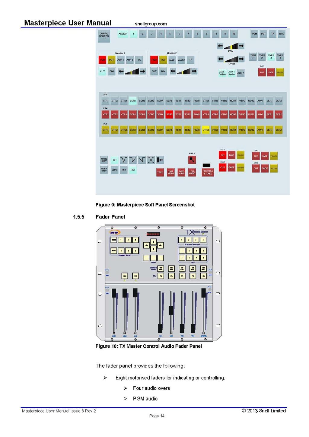
14
15 Lead audio (PST bus) Masterpiece User Manual Lag audio (PGM bus) Master audio Control of all of the above for up to 4 AES levels Pre Fade Listens for all audio overs Four Remote start buttons Multi-channel control of up to 6 mixers 1.6 Configuring the System The Masterpiece mixer is configured both from the control panel screen, and using switches and ini files within the 2U frame. The following is a list of locations and what configuration settings can be accessed: Mixer ini files - see section 3.4 Audio over to mixer level mapping Audio gain control for all levels DSK enable (via a license number) Video standard Number of audio levels 1 to 8 IP address for mixer interface 2330 Switch settings - see section 0 Single or multiple audio over mode PGM audio gain mode (live or next transition) DHCP or fixed IP address for automation interface 2330 ini file - see section 3.3 Fixed IP address for automation interface Transition mode for DVE (left in or removed) Remote mixer/panel connection mode (used by automation) Mixer name (used by automation) Control panel operator screen - see section 5.1 DSK clip and gain (effects mode only) DSK self or external keying mode Audio gain (+/-12db) control for levels 1 to 4 Audio track shuffling for levels 1 to 4 DVE selection, previewing and switching Page 15
16 Masterpiece User Manual Control Panel configuration screen (PIN protected) - see section 7.1 DSK mode (caption or effects) DSK enable Local or External (Aurora) router control Source names (local router only) Destination numbers (local router only) Number of audio levels 1 to 4 DVE/DSK path sequence Fade to Black position Page 16

17 Masterpiece User Manual 2 System Interconnections The following diagram (figure 11) shows a typical system with interconnections between the router and the mixer. The router passes video signals with embedded audio, and separate router outputs are connected to the mixer for video and audio mixing, meaning that a minimum of 4 router outputs is required. DVE PGM, PST INTERNAL DVE CTRL AS WELL DSK 1 TO 4 KEY & FILL DVE BACK & FG 2, PREVIEW VIDEO MIXER PGM, PST, PREVIEW & CLEAN FEEDS INPUTS VIDEO/AUDIO ROUTER PGM+E, PST+E OVERS 1 TO 8 AUDIOMIXER EXTERNAL CONTROL OFVIDEO MIXER PGM & CLN FD (EMBEDDED), MONITOR 1 & 2 OR EXTERNAL RS 422 ROUTER INTERNAL RS CONTROLLER EXTERNAL CONTROL OF AUDIO MIXER UMD EXTERNAL DVE VTR 1 AURORA ROUTER CONTROLLER TEST CAM 1 SECOND PANEL & FADER PANEL PORTS 16 GPI O/PS 3 VTR CONTROL OR RS 422 ROUTER & 20 VTR CONTROL AUTOMATION (RS 422 OR ETHERNET) SOURCE ASSIGN PANEL TX 500 FADER PANEL TX 520/510 PANEL Figure 11: System Interconnections The mixer can be considered as 3 components, the video mixer, audio mixer and 2330 Control Card. The video and audio mixers can be controlled externally, from an existing Snell mixer, such as the TX500, in which case the 2330 control card will not be fitted. D-type connectors are supplied on the rear panel for this purpose. 2.1 Router Connection There are two methods of controlling the video router, known within the system configuration as Local and External (see section 7.6.1) Local control requires a direct connection from the mixer router RS422 port to the router control port, which must be configured for General Switcher Protocol. This configuration maps the router sources directly to the channel buttons on the mixer Page 17
18 Masterpiece User Manual control panel. Router destination numbers are configured within the system configuration accessible through the control panel (see section 0). External control requires the connection of an Aurora controller, to which the mixer will connect as if it where a control panel, using Multidrop protocol. The Aurora control system will include a Source Assignment panel, which will allow any source under Aurora control, to be assigned to the mixer channel buttons. 2.2 Video Connections OUTPUTS PROG 1 PROG 2 PROG 3 PST MIX CLN FDA MIX CLN FDB CLN FDA CLN FDB PRV A PRV B PRV DVE EXT DVE EXT DVE PREVIEW PROG PST KEY 1 FILL 1 KEY 2 FILL 2 KEY 3 FILL 3 KEY 4 FILL 4 PROG+E PST+E DVE BACK DVE FG2 INPUTS Figure 12: Masterpiece Video Rear Connections KEY 1 FILL 1 KEY 3 FILL 3 EXT DVE DVE BACK DVE FG2 DVE Module Frame Store KEY 2 FILL 2 KEY 4 FILL 4 Logo Store DVE PVW PST PREVIEW Mixer K1 K2 K3 K4 FTB DSK PREVIEW PATH Embedder PRV A PRV B PROG1 PROG2 PROG3 (HD STANDARDS ONLY) EXT DVE CLN FDA MIXER CLEAN CLN FEED FDB A & B Figure 13: Video Path Block Diagram PST Video feeds of the router Programme and Preset outputs must be connected to the mixer. To achieve flexibility, the DSK mixer inputs may also be connected to router outputs, in order that different key sources can be selected using an external control panel. In HD systems, if it is intended to use the mixer DSK Preview function, the Preview input must be connected to a video feed; commonly this is connected to the router output being switched by the Auxiliary buss. Two identical Preview outputs are provided. Two identical Mixer Clean Feed outputs are also provided, these are copies of the Programme signal after mixing but before any key signals or DVE moves are applied. These are embedded with clean feed audio, which is a copy of Programme audio before any audio overs are added. Page 18
19 Masterpiece User Manual Each keyer requires a Key and Fill video signal, unless they are configured for Self Keying in to Operator Settings (see section 5.1), in which case only a Fill signal is required. The internal DVE module can accept a feed of a second foreground, the first foreground is provided internally by any point in the programme path, an input is also provided for a background. The need for these signals depends on the DVE sequence loaded: some sequences do not require a second foreground. DVE sequences are loaded and previewed via the control panel and a separate DVE Preview output is provided on the mixer. An external DVE unit may be connected and controlled by Masterpiece, currently only the Snell & Wilcox Magic Dave is supported; for this purpose, video in and out connections are provided (EXT DVE), as well as a serial control connection (DVE). 2.3 Audio Connections INTERNAL CLEAN FEED VIDEO INTERNAL PGM VIDEO PGM PGM + E EXTRACTOR DELAY AES EMBEDDER MIX CLN FDA MIX CLN FDB PST PST + E 8 x AES Inputs EXTRACTOR DELAY DOLBY DECODER DOLBY DECODER AES AUDIO ROUTING Figure 14: Audio Path Block Diagram AUDIO MIXER AUDIO VOICE OVERS 3 AUDIO ROUTING EMBEDDER DOLBY ENCODER DAC AES PROG1 PROG2 PROG3 MON 1 MON 1 MON 2 EXTERNAL DOLBY ENCODER IN/OUT OUTPUTS COMP VIDEO OUT PROG 1 PROG 2 PROG 3 PST MIX CLN FDA MIX CLN FDB CLN FDA CLN FDB PRV A PRV B PRV DVE EXT DVE EXT DVE PREVIEW DOLBY IN/OUT PROG PST KEY 1 FILL 1 KEY 2 FILL 2 KEY 3 FILL 3 KEY 4 FILL 4 PROG+E PST+E DVE BACK DVE FG2 AES OVERS IN + MONITOR OUT INPUTS Figure 15: Masterpiece Audio Rear Connectors The PGM and PST audio inputs to the mixer (labelled PGM+E and PST+E) are video signals with embedded audio; up to 8 AES levels of audio are extracted internally by the mixer, creating 16 mono levels internally, which can be assigned to different mixer transition blocks. These inputs are usually separate to the video inputs so that split transitions and audio break-away can be achieved. However, if these features are not required, and the user has a restricted number of router Page 19
20 Masterpiece User Manual outputs available, the audio can be extracted from the same video signals as used for the video mixing. This limits the type of mixer transition possible, and it is recommended that this is not used unless essential. This configuration requires a change to the HD_MIXER.INI file (see section 3.4). The PGM and PST inputs must be connected to router outputs. Delay may be manually inserted into selected audio paths using the HD_MIXER.INI file (see section 3.4). This will be required if a DVE has been included in the corresponding video path, for instance. Three AES audio outputs and one AES input are supplied for an external Dolby Encoder; this option is also configured in the HD_MIXER.INI file. The audio routing section of the mixer allows channels to be shuffled, so that different channels can be routed to different outputs. The first 8 channels (four levels) can be shuffled through the Operator configuration screen on the control panel (see section 5.1). The audio mixer section performs the mix/wipe/fade transition between PGM and PST, followed by the cut back between the two busses. A further mixing stage routes and mixes the 8 AES audio over input signals. These are balanced AES inputs via a D-type connector. Since each audio level within the mixer is capable of having up to 4 audio overs added to it, a choice must be made how these are to be allocated. There are 3 template options for this configuration, the selection of which is defined in the HD_MIXER.INI file (see section 3.4). Bespoke audio configurations can be created, making the system highly flexible. The template options are: Configuration 1 PRO-BEL_AUDIO_1.INI: 1 separate AES audio over for each of the 8 audio levels (audio overs 2 to 4 will not function) AES INPUT LEVEL AUDIO OVER Configuration 2 PRO-BEL_AUDIO_2.INI: Page 20
21 Masterpiece User Manual 2 audio overs for each of the 8 audio levels, but the overs for levels 1 to 4 will also route to levels 5 to 8 (audio overs 3 and 4 will not function) AES INPUT LEVEL AUDIO OVER Configuration 3 PRO-BEL_AUDIO_3.INI: 4 audio overs for each of the 8 levels, but the overs for level 1 will also route to levels 3, 5 and 7, and the overs for level 2 will also route to levels 4, 6 and 8 AES INPUT LEVEL AUDIO OVER A further configuration allows 4 of the AES input signals to be used as discrete AES PGM and PST inputs. This option is for installations that do not use embedded audio. A maximum of 2 levels are permitted in this configuration, with 2 audio overs for each level. Configuration 4 PRO-BEL_AUDIO_4.INI: 2 audio overs for each of the 2 audio levels, all signals are separate AES inputs, including PGM and PST for levels 1 and 2 Page 21
22 Masterpiece User Manual AES INPUT LEVEL 1 PGM PST MIX PGM PST LEVEL 2 MIX AES INPUT 56 AUDIO OVERS 1&2 MIX MIX AUDIO OVERS 1&2 AES INPUT Loudspeaker monitoring is provided either as 2 AES outputs, corresponding to Monitor1 and Monitor2 on the control panel; or a single stereo analogue output, in which case only Monitor1 will function. This selection is made using switches on the main mixer card (see section 3.8). Page 22
 OR")
23 Masterpiece User Manual 2.4 Control Connections MASTERPIECE MIXER VIDEO MIXER EXTERNAL CONTROL OF VIDEO MIXER 8 GPI O/PS ETHERNET INPUTS VIDEO/AUDIO ROUTER AUDIOMIXER EXTERNAL CONTROL OF AUDIO MIXER VIDEO (COMPOSITE & VGA) OR EXTERNAL RS 422 ROUTER 2330 CONTROLLER TIMECODE UMD EXTERNAL DVE VTR 1 AURORA ROUTER CONTROLLER TEST CAM 1 SECOND PANEL & FADER PANEL PORTS 16 GPI O/PS 3 VTR CONTROL OR RS 422 ROUTER & 20 VTR CONTROL AUTOMATION (RS 422 OR ETHERNET) SOURCE ASSIGN PANEL TX 500 FADER PANEL TX 520/510 PANEL Figure 16: Control Connections The following table describes all control connections to the Masterpiece mixer as shown above. It is noted that the mixer may not contain a 2330 control card, in which case, connections associated with this card will not work, and the video and audio mixers will have to be controlled from an external system. NAME TYPE STANDARD PURPOSE AUTO RJ45 RS422 Automation control of mixer using SW-P-32 protocol DVE RJ45 RS422 Control of external DVE VTR1 RJ45 RS422 Direct control of VTR from control panel, OR, control of RS422 router (see section 7.6.4) VTR2 RJ45 RS422 Direct control of VTR from control panel, OR, input to RS422 router (see section 7.6.4) VTR3 RJ45 RS422 Direct control of VTR from control panel, OR, input to RS422 router (see section 7.6.4) FADER 1 RJ45 RS422 Connection to Fader Panel 1 FADER 2 RJ45 RS422 Connection to Fader Panel 2 Page 23
24 Masterpiece User Manual NAME TYPE STANDARD PURPOSE ROUTER RJ45 RS422/RS232 Direct control of video/audio router, OR, connection to Aurora panel port (see section 7.6.1) UMD RJ45 RS485 Connection for up to 16 Snell Under Monitor Displays ETHERNET (RIGHT SIDE) ETHERNET (LEFT SIDE) RJ45 ETHERNET Automation control of mixer using SW-P-32 protocol RJ45 ETHERNET Not supported TIMECODE 9 PIN D SOCKET LTC Drives timecode display on control panel and reference for time-stamped automation commands RS232 DEBUG 9 PIN D SOCKET RS232 Debugging mixer purposes only CONTROL PANEL 1 CONTROL PANEL 2 15 PIN D SOCKET 15 PIN D SOCKET 2 off RS422 Connection to Control Panel 1 2 off RS422 Connection to Control Panel 2 VIDEO MIXER 9 PIN D SOCKET RS422 External control of video mixer, e.g. TX500 mixer AUDIO MIXER 9 PIN D SOCKET RS422 External control of audio mixer, e.g. TX500 mixer GPIO 1-8 MIXER 9 PIN D SOCKET Indication of overs and DSK s and logo control GPIO 1-16 CONTROL 25 PIN D SOCKET GPI Outputs: Open Collector, +5V Off, 0V On Can be configured as channel cues, bus active or pre-roll. Page 24
25 Masterpiece User Manual 2.5 Pin Outs GPIO 1-8 MIXER CONTROL PANEL 1 CONTROL PANEL 2 GPIO 1-16 TX CONTROL ETHERNET VGA OUT PSU & FAN MONITOR OUT RS232 DEBUG VIDEO MIXER AUDIO MIXER AUTO DVE VTR1 VTR2 VTR3 FADER 1 FADER 2 ROUTER UMD V AC ~ 1.1A 50/60hZ REF B&B REF TR1 TIMECODE PROG 1 PROG 2 PROG 3 PST MIX MIX CLN FDA CLN FDB CLN FDA CLN FDB PRV A PRV B PRV DVE EXT DVE EXT DVE PREVIEW USB 1USB2 COMP VIDEO OUT DOLBY IN/OUT REF B&B REF TR1 PROG PST KEY 1 KEY 2 FILL 1 FILL 2 KEY 3 FILL 3 KEY 4 FILL 4 PROG+E PST+E DVE BACK DVE FG2 AES OVERS IN + MONITOR OUT V AC ~ 1.1A 50/60hZ ETHERNET Figure 17: Rear View of Masterpiece PSU/FAN Fail + Bypass Figure 18: PSU/FAN and Bypass Connector Pin Number Function 1 PSU 1 Normally closed contact 2 PSU 1 Normally open contact 3 PSU 2 Common contact 4 FAN Normally closed contact 5 FAN Normally open contact 6 BYPASS Common contact 7 BYPASS control GND 8 BYPASS control GND 9 PSU 1 Common contact 10 PSU 2 Normally closed contact 11 PSU 2 Normally open contact 12 FAN Common contact 13 BYPASS Normally closed contact 14 BYPASS Normally open contact 15 BYPASS control + 12 Volts Control Panel 1/2 Figure 19: Control panel 1/2Connector Pin Number Function 1 RX + 2 TX - Page 25
26 Masterpiece User Manual Pin Number Function 3 GND 4 n/c 5 n/c 6 n/c 7 PPM- 8 GND 9 RX- 10 TX+ 11 n/c 12 n/c 13 GND 14 n/c 15 PPM+ AES Overs and Monitor Figure 20: AES Overs and Monitor Pin Number Function 1 AES Over 1-2 AES Over 1+ 3 GND 4 AES Over 2-5 AES Over 2+ 6 AES Monitor 1-7 AES Monitor 1+ 8 GND 9 AES Over 3-10 AES Over GND 12 AES Over 4-13 AES Over AES Over 5-15 AES Over GND Page 26
27 Pin Number Masterpiece User Manual Function 17 AES Over 6-18 AES Over AES Monitor 2-20 AES Monitor AES Over 7-22 AES Over GND 24 AES Over 8-25 AES Over 8+ Dolby Encoder In/Out Figure 21: Dolby Input Output Connector Pin Number Function 1 Dolby In- 2 Dolby In+ 3 OUT 1-4 OUT 1+ 5 OUT 2-6 OUT2+ 7 OUT3-8 OUT3+ 9 GND Timecode 9 Way D Figure 22: Timecode 9-Way "D" Connector Pin Number Function 1 Timecode+ 2 n/c 3 n/c 4 n/c 5 n/c Page 27
28 Masterpiece User Manual Pin Number Function 6 Timecode- 7 n/c 8 n/c 9 GND TX Control 16 GPIO 25 way D Figure 23: TX Control GPIO 25 Way Connector All GPI Outputs, open collector, +5V Off, 0V On Pin Number Function 1 GPIO 1 2 GPIO 2 3 GPIO 3 4 GPIO 4 5 GPIO 5 6 GPIO 6 7 GPIO 7 8 GPIO 8 9 GPIO 9 10 GPIO10 11 GPIO GPIO GPIO GPIO GPIO GPIO n/c 18 n/c 19 n/c 20 GND 21 GND 22 GND 23 GND Page 28
29 Pin Number Masterpiece User Manual Function 24 GND 25 GND Mixer/Key RS485 Control 9 Way D Figure 24: Mixer/Key RS485 Control 9-way "D" Connector Pin Number Function 1 GND 2 TX- 3 RX+ 4 GND 5 n/c 6 GND 7 TX+ 8 RX- 9 GND Mixer/Keyer RS232 Debug 9 Way D Figure 25: Mixer/Keyer RS232 Debug 9-way "D" Connector Pin Number Function 1 n/c 2 TX 3 RX 4 n/c 5 GND 6 n/c 7 n/c 8 n/c 9 GND Page 29
30 Masterpiece User Manual Mixer/Keyer GPIO 9 Way D Figure 26: Mixer/Keyer GPIO 9-way "D" Connector Pin Number Function 1 GPIO 1 2 GPIO 2 3 GPIO 3 4 GPIO 4 5 GPIO 5 6 GPIO 6 7 GPIO 7 8 GPIO 8 9 GND The GPIO input and output circuit has an open collector output and an optocoupled input that needs pulling to GND to turn the input on. The GPIO output can sink up to 200 ma and have a maximum voltage of up to 24 V DC. The GPIO input just needs pulling to GND with an external device that can sink 20 ma. It looks as follows: GPIO - OUT +5V GPIO - IN GND 168R RS485 on RJ45 Connectors 8 1 Figure 27: RS485 on RJ45 Connector Pin Number Function - DEVICE Function - CONTROLLER 1 GND GND 2 GND GND 3 RX- TX- 4 TX+ RX+ Page 30
31 Masterpiece User Manual Pin Number Function - DEVICE Function - CONTROLLER 5 TX- RX- 6 RX+ TX+ 7 n/c n/c 8 n/c n/c RJ45 to 9 way D Connector adaptor cabling Figure 28: RJ45 to 9-way Connector Pin 9 way D Pin RJ45 Function 1 n/c GND 2 3 TX- 3 4 RX+ 4 1 GND 5 n/c n/c 6 2 GND 7 6 TX+ 8 5 RX- 9 n/c GND Page 31

32 Masterpiece User Manual 2.6 Control panel connections TX 520/510 Panel connections All connections to the TX 520/510 control panel are recessed at the rear. Each main frame is supplied with a 15m panel interconnect cable. The following connector pinouts are for the control outputs from the panel. 15 way D type fixed sockets Pin TXSYS1-6 BYPASS PSU MONITOR 1 TX + SW1 COMMON 5V (1) 2 RX- SW2 CLOSE 5V (1) 3 GND SW3 OPEN 5V (1) 4 n/c SW4 n/c 5 n/c SW5 COMMON 12V (1) 6 n/c SW6 CLOSE 12V (1) 7 PPM- SW7 OPEN 12V (1) 8 GND SW8 n/c 9 TX- n/c COMMON 5V (2) 10 RX + n/c CLOSE 5V (2) 11 n/c n/c OPEN 5V (2) 12 n/c n/c n/c 13 GND SW COMM COMMON 12V (2) 14 n/c 0V CLOSE 12V (2) 15 PPM + n/c OPEN 12V (2) The Bypass connector provides access to the Bypass switch control button row in the top left corner of the panel. By offering pin to pin compatibility with the ICON 8x1 switcher range, they can be used to provide an emergency bypass router facility for the TX 500. Page 32
33 25 way D type fixed sockets Masterpiece User Manual Pin SPARE 1 SPARE 2 AUTOMATION 1 SW1 SW1 AUTO ON 2 SW3 SW3 HOLD 3 SW5 SW5 SKIP NEXT 4 SW7 SW7 PREVIEW 5 n/c n/c RECUE 6 LED1 LED1 TAKE 7 LED3 LED3 DELETE 8 LED5 LED5 UNDELETE 9 n/c n/c ARROW UP 10 LED7 LED7 ARROW DOWN 11 n/c n/c STANDBY 12 n/c n/c EXPLODE BREAK 13 n/c n/c AUTO LED 14 SW2 SW2 HOLD LED 15 SW4 SW4 N/C 16 SW6 SW6 PREVIEW LED 17 SW8 SW8 N/C 18 SW COMMON SW COMMON N/C 19 LED 2 LED 2 TAKE LED 20 LED4 LED4 N/C 21 LED6 LED6 EXPLODE LED 22 LED8 LED8 12V OUT 23 LED COMMON LED COMMON LED COMMON 24 n/c n/c SW COMM 25 OV OV OV OUT The connectors Spare 1 and 2, provide access to the two rows of eight pushbuttons below the Bypass switch control button row. These buttons can be used to control any equipment requiring a closing contact. However in systems with multi level audio, or if the panel is to provide control of more than one system, these buttons are used for that purpose and are therefore not available externally. The Automation Port connections provide MIP (manual intervention panel) compatability with legacy Compass/Sectant automation systems. These connections enable any equipment, requiring a closed contact to be interfaced to the panel Automation buttons. Page 33


34 Masterpiece User Manual TX 502 Panel connections For correct operation, the panel address switch should be set to address 0, and the panel mode switches should be set to 0 RS485 In 9 way D type fixed sockets Pin Function 1 N/C 2 TX- 3 RX+ 4 GND 5 N/C 6 GND 7 TX+ 8 RX- 9 n/c Interconnecting cable wiring detail 15 way plug to 9 way D type plug Masterpiece Panel 1/2 TX Page 34
35 2.6.3 Audio fader panel connections Masterpiece User Manual SPARE FADERS OPEN / PFL PSU ALARM GPI / REM START PORT PSU A ETHERNET PSU B Control and PSU alarm Just like the main TX500 control panel, the fader panel can be connected up to 6 main frames for multi-channel operation, these 9 way D type connectors are labelled 1 to 6 and all have the following pinout. The pinout for the PSU alarm is also shown below: Pin Port 1 to 6 PSU alarm 1 GND GND 2 TX- PSU 1 RELAY COM 3 RX+ PSU 1 RELAY S/C FAIL 4 GND PSU 1 RELAY O/C FAIL 5 N/C PSU 2 RELAY COM 6 GND PSU RELAY S/C FAIL 7 TX+ PSU RELAY O/C FAIL 8 RX- n/c 9 GND n/c GPI/Remote start This connector provides both switch closures for up to 5 devices, and access to the 5 LEDs inside the buttons. The switch closures are normally-open contacts labeled REMOTE START 1, 2 etc. and use the pin labeled REMOTE START SW COMMON as the second connection. To activate the LEDs, the user must supply +5Volts to the pin labeled REMOTE START LED COMMON, and a connection to 0 Volts on the pins labeled REM START CATHODE 1, 2 etc. Pin GPI/REM START Pin GPI/REM START 1 NOT USED 14 NOT USED 2 NOT USED 15 REMOTE START 1 3 REMOTE START 2 16 REMOTE START 3 4 REMOTE START 4 17 REMOTE START 5 5 n/c 18 REMOTE START SW COMMON Page 35
36 Masterpiece User Manual Pin GPI/REM START Pin GPI/REM START 6 NOT USED 19 n/c 7 NOT USED 20 REMOTE START CATHODE 1 8 REMOTE START CATHODE 2 21 REMOTE START CATHODE 3 9 n/c 22 REMOTE START CATHODE 5 10 REMOTE START CATHODE 4 23 REMOTE START LED COMMON 11 n/c 24 n/c 12 n/c 25 GND 13 n/c Spare buttons This connector provides both switch closures for the 8 Spare buttons, and access to the 8 LEDs inside the buttons. The switch closures are normally open contacts labeled SW 1, 2 etc. and use the pin labeled SW COMMON as the second connection. To activate the LEDs, the user must supply +5Volts to the pin labeled LED COMMON, and a connection to 0 Volts on the pins labeled SW CATHODE 1, 2 etc. Pin SPARE Pin SPARE 1 SWITCH 1 14 SWITCH 2 2 SWITCH 3 15 SWITCH 4 3 SWITCH 5 16 SWITCH 6 4 SWITCH 7 17 SWITCH 8 5 N/C 18 SWITCH COMMON 6 SWITCH CATHODE 1 19 SWITCH CATHODE 2 7 SWITCH CATHODE 3 20 SWITCH CATHODE 4 8 SWITCH CATHODE 5 21 SWITCH CATHODE 6 9 N/C 22 SWITCH CATHODE 8 10 SWITCH CATHODE 7 23 LED COMMON 11 N/C 24 N/C 12 N/C 25 GND 13 N/C Page 36
37 Masterpiece User Manual Fader open/ PFL These are individual switch contacts on each fader which close when the fader is off its end stop. The PFL switch closes when any PFL button is active. Pin FADER OPEN/PFL Pin FADER OPEN/PFL 1 FADER COMMON 1 14 FADER ACTIVE 1 2 FADER COMMON 2 15 FADER ACTIVE 2 3 FADER COMMON 3 16 FADER ACTIVE 3 4 FADER COMMON 4 17 FADER ACTIVE 4 5 FADER COMMON 5 18 FADER ACTIVE 5 6 FADER COMMON 6 19 FADER ACTIVE 6 7 FADER COMMON 7 20 FADER ACTIVE 7 8 FADER COMMON 8 21 FADER ACTIVE 8 9 N/C 22 N/C 10 N/C 23 N/C 11 PFL COMMON 24 PFL ACTIVE 12 N/C 25 N/C 13 N/C Page 37
38 Masterpiece User Manual 3 TX-2330 Configuration 3.1 Introduction This card is the central controller for the Masterpiece Mixer. This card is optional since the mixer can be controlled from an external system such as the TX500 Series Master Control Mixer, which itself will contain a TX-2330 control card. The TX-2330 can be considered as a PC on a card, and runs a real-time operating system with the core program held in flash memory on a pluggable chip. The controller system configuration is also written to the flash memory, which may be backed up using a PC connected to the Ethernet port. Communication to most other components in the system is via built-in serial links, there are also 16 GPIs on the card. The interface to the automation system is either via an RS422 or Ethernet connection. The following diagram shows the card configuration switches and LEDs, most other components are not shown: CONFIG LK AC SP HD ACT RESET RST POK Figure 29: 2330 Control Card 3.2 Switches and LED s CONFIG LK AC SP HD ACT RESET RST POK Figure 30: TX-2330 Control Card Switches and LED's Page 38
39 Masterpiece User Manual LED FUNCTION NORMAL STATUS LK Ethernet link OK Yellow AC Green when Ethernet link active Off SP Ethernet speed, Red=100Mbit Red HD Yellow when Hard Disk being accessed Off/flashing ACT Module active Green RST Red when Module in reset Off POK Power OK Green Switch number Function Normal setting SW3 7 Ethernet address, DHCP (Up), Fixed in Network.ini file (Down) 6 TEST MODE (ON = ENABLED) In test mode the system runs from a RAM copy of the configuration file allowing the configuration file to be copied or overwritten using FTP transfer. The RAM copy is a copy of the last data written to the configuration file since the 2330 was reset. The 2330 will need to be reset to take note of each change of the switch position. DOWN/ON UP/OFF 5 Remote logging screen enabled (Down) UP/OFF 4 Not used SW2 3 Audio take/lead. Take enabled (Up), lead enabled (Down) DOWN/ON 2 Not used UP/OFF 1 OFF = Normal Gain Mode, ON = PGM Gain Mode. UP/OFF In PGM Gain mode any adjustments to the gain will not be applied to the PGM bus until the next transition (Take). Note this makes the PGM button (in audio set up) on the Main TX panel obsolete 0 Single audio over mode (Down)/Multi-over mode (Up) UP/OFF Page 39
40 Masterpiece User Manual Diagnostic LED indications: LED FUNCTION NORMAL STATUS 7 Flashes at 2 Hz to show card active and video reference detected Flashes at 1Hz to show card active and NO video reference detected Flashes Flashes 6 DVE timeout (If configured) Off 5 Automation timeout Off 4 Panel 1 and Panel 2 timeout Off 3 Audio matrix / Audio Aurora timeout Off 2 Video matrix / Video Aurora timeout Off 1 Audio mixer/fader panel timeout Off 0 Video mixer/ DSK timeout Off Note: LEDs used for timeout are off if communications with the corresponding device are present. If communications are lost, or there is no device connected, then the LED is illuminated. 3.3 Configuration File Every Masterpiece system has a system configuration file, which is held in nonvolatile flash memory. The data held in this file is critical for the correct operation of the system, and therefore it is advisable that a backup copy of this file is kept for each system. The configuration data is essentially all the details entered into the Config screens in the TX500 control panel screen Requirements The TX-2330 control card is equipped with an Ethernet port and an FTP Server, and it is these facilities that can be used to backup and restore the system configuration. The file TX500Series1.cfg contains configuration data. Network.ini contains network initialisation data. All Masterpieces will be shipped with a fixed IP address configured (normally ), which the user must know before they can proceed. The user will also need to connect the Masterpiece to a Local Area Network using a standard CAT5 cable and the Ethernet port on the rear of the main control frame. A PC needs to be available on the same LAN, the operation can then be carried out from the Command Prompt or using Microsoft Internet Explorer V6, or beyond. Finally, the TX-2330 control must be put into Test Mode using switch 6, which is accessible via the front edge, after which a reset must be performed. The Masterpiece will be operational while in this mode, however, any changes made in Page 40

41 Masterpiece User Manual the configuration data will not be saved (this mode stops the flash being updated). Therefore it is advisable to always return the switch to the OFF/UP Normal position CONFIG CONFIG Switch 6 OFF/UP Normal DOWN/ON Test Mode LK AC SP HD LK ACT SP HD ACT RESET RST RESET POK RST POK Reset after changing switch setting Backing up Using Compact Flash Reader Remove the compact flash from the 2330 TX Controller and place in a compact flash reader. This will appear as another drive within the standard windows operating system. The configuration files can then be copied, saved or edited Using FTP From the Command Prompt, the user must first check communication with the TX500 by Pinging its IP address: If successful, the following command sequence will result in the TX500Series1.cfg file being copied onto the users C: drive: Page 41
, and resetting the 23")

42 Masterpiece User Manual Note that the password, when prompted, is: *+ }.? To restore the configuration from the same PC, the following command is used: PUT TX500Series1.cfg The session is closed by typing Disconnect, after which the TX500 must be put back into Normal Mode (using Switch 6), and resetting the 2330 card From Internet Explorer After launching Internet Explorer, type in ftp:// followed by the IP address of the TX500. Type in the following user name and password when prompted: User: Pro-Bel Password: *+ }.? The resulting screen will show the available files, which may be saved by right mouse clicking on the highlighted file and selecting Copy to folder. Page 42
43 Masterpiece User Manual The file may be restored to the TX500 by using the PCs Copy function in Windows Explorer, and pasting the file into the screen shown above Configuring an IP Address The Masterpeice can only have its address changed after a successful connection has been made to the FTP server, as described in the previous two sections. The user must then retrieve the NETWORK.INI file and edit it before re-applying it to the TX-2330 control card. The NETWORK.INI file will appear similar as follows: ;====================================== ;TX500 Series Master Control - INI file ; ;This contains the settings and delays ;to interface to the 2330 hardware ; ; Version V1.05 ; Date 16/10/2008 ;====================================== [NETWORK] IPAddress=xxx.xxx.xxx.xxx SubNetMask=xxx.xxx.xxx.xxx DefaultGateway= DNSAddress= ; Ethernet CFG ; 0=Auto, ; 1=10M Half Duplex, 2=10M Full Duplex, ; 3=100M Half Duplex, 4=100M Full Duplex (default) EthernetCFG=4 [AUTOMATION] Port=3002 Nagling=0 [DEBUG] GenMsgPort=3004 RTIPDiag=0 [DEVICENAMES] RemotePortSwitching=0 MixerID=TXMixer1 Port1ID=PanelPt1 Page 43
44 Masterpiece User Manual Port2ID=PanelPt2 Port3ID=FaderPt1 Port4ID=FaderPt2 EnableMixerName=1 Port1ClientMode=0 Port2ClientMode=0 Port3ClientMode=0 Port4ClientMode=0 FaderPanelPort1Tied=1 FaderPanelPort2Tied=1 [TRANSITIONS] DVEAutoOff=1 VideoSBDelay=8 AudioSBDelay=8 VideoEMBEDAudioSBDelay=16 AudioEMBEDAudioSBDelay=16 VideoDVESBDelay=24 AudioDVESBDelay=24 ResetVideoMixerPort=0 ResetDVEPort=0 ManualLagMode=0 HDMixerDVE=0 AudioPreviewMode=0 AudioGainMode=0 UseExtendedAudioMsgPort1=0 UseExtendedAudioMsgPort2=0 [SYSTEMSETUP] AudioMixer=1 VideoMixer=1 DSKs=2 AudioRouter=1 VideoRouter=1 DVE=0 PanelPort1=1 PanelPort2=0 [CHANNELNAMES] Port1ExtDisplayMode=0 Port2ExtDisplayMode=0 [GPIMACROS] Page 44
45 GPIMacroEnabled=0 SourceSpecific=1 SourceType=Audio ExclusiveMode=1 Macro1File=TestSw1.mac Macro2File=TestSw2.mac Macro3File= Macro4File= Macro5File= Macro6File= Macro7File= Macro8File= Masterpiece User Manual [LOCALROUTERCFG] VideoDestOffset=0 VideoSourceOffset=0 Audio1DestOffset=0 Audio1SourceOffset=0 Audio2DestOffset=-1 Audio2SourceOffset=-1 Audio3DestOffset=-1 Audio3SourceOffset=-1 Audio4DestOffset=-1 Audio4SourceOffset=-1 Other configuration settings [NETWORK] Section The values stored in this section are only used when DIL switch 7 is set to use fixed IP address (ON) The IPAddress field is the fixed IP address to be used. It must not have leading zeros on any part of the address (except for a single zero when the value is zero). The SubNetMask is the value for the network subnet mask address. This field must not have leading zeros on any part of the address (except for a single zero when the value is zero). The DefaultGateway is the address of the gateway used when messages need to be sent outside the local LAN. This field must not have leading zeros on any part of the address (except for a single zero when the value is zero). The DNSAddress value is the address of the DNS server. This field must not have leading zeros on any part of the address (except for a single zero when the value is zero). This is not currently used so should be set to Page 45
46 Masterpiece User Manual The EthernetCFG value is the setting used to set the Ethernet Port speed and duplex. The available options are: 0 (AUTO), 1 (10M Half Duplex), 2 (10M Full Duplex), 3 (100M Half Duplex) and 4 (100M Full Duplex, default). Any other value will cause the default value to be set [AUTOMATION] Section The Port field is used to define which port the software uses to listen on for automation commands coming from the network. Note: Only one client connection is allowed on the network to the TX controller for automation commands [DEBUG] Section The GenMsgPort field is used to define which port the software uses to listen on for the remote logging functions coming from the network. The RTIPDiag field is used to turn on low-level network diagnostic messages (0 = OFF, 1 = ON). Under normal circumstances this value should be set to 0. Note: Only one client connection is allowed on the network to the TX controller for remote logging functions [DEVICENAMES] Section This section defines whether the TX500 supports remote connection and disconnection of the Main TX Panel and Fader Panel ports via the automation interface as well as the name of the TX500 and the names of its main panel and fader panel ports. The RemotePortSwitching field enables remote port switching when set to 1 and disables it when set to 0. The MixerID field is the name for the mixer. The Port#ID fields are for the following: - Port1ID is the name for main panel port 1, Port2ID is the name for main panel port 2, Port3ID is the name for fader panel port 1, and Port4ID is the name for fader panel port 2. All names are a maximum of 8 characters and are used in the automation protocol (SW-P-32 command 0x19) for the remote panel switching function. EnableMixerName=1 allows the name of the mixer ( MixerID ) to be sent to the panel ports. Page 46
47 Masterpiece User Manual PortxClientMode=1 (x = 1, 2, 3 or 4 where 1 or 2 indicates panel ports 1, 2; and 3 or 4 indicates fader ports 1 or 2) enables the specified port to operate in multi-client mode. This is used by the Procion system to allow multiple panel clients to connect to a mixer via a single RS422 port. PortxClientMode=0 is the default mode that sets the port to operate with normal TX hardware panels. Note: only the normal TX panel ports support mult-client mode at present. FaderPanelPortxTied=1 allows the Fader panel port to be connected at the same time a its associated panel port is connected and vice versa. When the panel port is in multi-client mode then the Fader Port PortxID needs to be set to the same name as the client name of the Procion panel that it is tied to [TRANSITIONS] Section This section defines the various effects and delay timings during transitions. The DVEAutoOff defines whether the DVE is automatically removed from the signal path at the end of a transition (when set to 1) or left in (0). The VideoSBDelay is the time when the video mixer switches back to its normal PGM crosspoint after the PGM bus has switched on the router. This value is used when there is no DVE in the video signal path and is expressed in multiples of 5ms. The AudioSBDelay is the time when the audio mixer switches back to its normal PGM crosspoint after the PGM bus has switched on the router. This value is used when there is no DVE in the video signal path and is expressed in multiples of 5ms. The VideoEMBEDAudioSBDelay is the time when the video mixer switches back to its normal PGM crosspoint after the PGM bus has switched on the router when embedded audio is used. This value is used when there is no DVE in the video signal path and is expressed in multiples of 5ms. The AudioEMBEDAudioSBDelay is the time when the audio mixer switches back to its normal PGM crosspoint after the PGM bus has switched on the router when embedded audio is used. This value is used when there is no DVE in the video signal path and is expressed in multiples of 5ms. The VideoDVESBDelay is the time when the video mixer switches back to its normal PGM crosspoint after the PGM bus has switched on the router. This value is used when there is a DVE in the video signal path and is expressed in multiples of 5ms. The AudioDVESBDelay is the time when the audio mixer switches back to its Page 47
48 Masterpiece User Manual normal PGM crosspoint after the PGM bus has switched on the router. This value is used when there is a DVE in the video signal path and is expressed in multiples of 5ms. The ResetVideoMixerPort determines whether the background reset of the Video Mixer port is enabled or not. If enabled (set to 1) the Video Mixer port will be reset once an hour or every three consecutive messages where a response was not received, otherwise set to 0 (zero) the function is disabled. The ResetDVEPort determines whether the background reset of the DVE port is enabled or not. If enabled (set to 1) the DVE port will be reset once an hour or every three consecutive messages where a response was not received, otherwise set to 0 (zero) the function is disabled. The HDMixerDVE defines how the Master control mixer controls the operation of a DVE, if installed, on the system. Set to 0 then system assumes the DVE is an external one, with the mixer taking full control of the DVE and communicates with it on its own dedicated multi-drop port. This is the default operation. If set to 1 then the control is as mode 0, but the DVE is assumed to be an internal one with communications now using the same multi-drop port as the main Video Mixer with an address 0x36h. If set to 2 then the mixer will run a DVE Simulation mode. This mode can be selected when using and external DVE that requires no communications with the Master Control. The DVE input will be switched as normal using the DVE button on control panels or automation commands. This option is only available with a frame store module installed. The ManualLAGMode defines the operation of the Manual Fader panel Lag button. If set to 1 then any Automation Lag operations can be overridden or cancelled by the operator pressing the Lag button in a User knows best situation. If cleared (set to 0) then normal operation is assumed. The AudioPreviewMode value allows different audio routing/gain values for the same channel on different busses (PGM, PST, AUX1). When this flag is enabled (1) it allows back-to-back transitions on the same channel to have different audio routing/gains. The following rules apply whether changed from a panel (hard or soft) or automation: Adjusting PGM bus audio will change the audio for PGM/AUX1/AUX2 busses for the selected PGM bus channel but will only change the PST bus if the PST bus has a different channel selected to the PGM bus. Adjusting the PST bus audio will only change the PST bus audio. Adjusting the AUX1 bus audio will change the AUX1/AUX2 busses for the selected AUX1 bus channel but will only change the PST/PGM busses if the Page 48
49 Masterpiece User Manual respective selected channels on the PST/PGM busses are different to the AUX1 bus. To use the above feature on a manual TX panel, V3.11 or above software for the hard panel or V1.18 or above software for the MCM soft panel will need to be used. When this flag is disabled (0), the default setting, the routing/gains are applied to all busses for that channel no matter which bus it was set on. The AudioGainMode value allows the gains to be applied according to the input channel routing (0, default) or directly to the audio outputs (1). The UseExtendedAudioMsgPort? value allows the separate audio routing/gain functionality to be used on an MCM soft panel. There are two configuration values, one for panel port 1 and one for panel port 2. Setting this value to 1 will allow an MCM soft panel (must be MCM V1.18 or above) to use the separate audio routing/gain features. If a hard panel or MCM soft panel V1.17 or below is being used on a panel port then the respective setting for that port must be set to 0 (zero), the default [SYSTEMSETUP] Section This section defines the expected system setup for the Status Poll to respond against. The AudioMixer defines if the system has an audio mixer present (1) or no mixer (0). The VideoMixer defines if the system has a video mixer present (1) or no mixer (0). The DSKs defines if the number of active DSKs present (1-4) or none (0). The AudioRouter defines if the system has an audio router present (1) or not (0). The VideoRouter defines if the system has a video router present (1) or not (0). The DVE defines if the system has a DVE present (1) or not (0). The PanelPort1 defines if the system has a Panel connected to port-1 (1) or not (0). The PanelPort2 defines if the system has a Panel connected to port-2 (1) or not (0). Note: Setting any of these values to Not present (0), even if there is, will force the Status Poll message to report no issues with that device even if the mixer has lost comms or disconnected. Page 49
50 Masterpiece User Manual [CHANNELNAMES] Section This section defines whether the extended channel name will be transmitted on a Panel Port. Extended Channel names consist of 8 ASCII characters as apposed to the existing 4 ASCII characters. This functionality is only possible with Aurora Controller V1.11 or greater and can only be displayed on MCM V1.16 or greater. The Port1ExtDisplayMode defines if the extended channel names are to be sent to Panel Port 1 (1) or disabled (0). The Port2ExtDisplayMode defines if the extended channel names are to be sent to Panel port 2 (1) or disabled (0). If this feature is enabled under Local Router control, the system will send out extended channel names that are made from centring the existing 4 ASCII name in 8 characters. Note: Enabling this functionality does not interfere with the existing channel names [GPIMACROS] Section GPI Macros were developed to extend the functionality of a TX Panel system without the use of an Automation Module. They utilise the GPI numbers 17 to 48 and therefore require the 2332 GPI Expansion card to be installed. The basic definition of a GPI Macros is an Automation command that is executed by the press of a Spare button from the TX Panel (TX520 see section 5.7, or TX510 see section 9.5.5). These commands are SW-P-32 based e.g. change the Audio Routing on a multi level system, and therefore, cannot be used on systems where Automation is already installed and used. The system only supports up to 8 separate GPI Macros and therefore 8 macro files. Note: Only 3 can be active at one time simultaneously Configuring GPI Macros In order to use the GPI Macro functions, the NETWORK.INI file needs to have the correct settings as to how these macro commands are to be executed. The GPIMacroEnable must be set to 1 to enable them. The GPI Macros only operate in one of two modes, either source specific or global. (For more details see section 10.4) Source specific means that the command being executed is performed on the current selected preset channel only. If the Source changes then the GPI Status lamps will change to indicate the status of the new channel. Global means that the command is executed system wide irrespective of the selected channel. To correctly set the mode of operation for the GPI Macro requires prior knowledge of the Automation command protocol SW-P-32. If the Source Specific mode is selected then the GPI Macro can show the status Page 50
51 Masterpiece User Manual of either the Video or Audio channel selected. If the command being executed is to change some parameters on the audio source then setting the Source Type to Audio means the system status will only follow the preset Audio channel. Likewise, setting it to Video will follow and display the status of the Video channel. If the sources are married then the default of Video can be assumed. If the Exclusive Mode flag is set then there will only be one GPI Macro active at one time. Pressing a subsequent GPI Button will firstly switch off the current GPI Macro button and run is associated Off command before running the newly selected Macro. If running in Non-Exclusive mode it is advisable not to have more than 3 Macros active at anyone time. GPI Macros are defined in the section Macro#File, where the # is numbers 1 to 8. The files are stored on the Compact Flash card along with the rest of the system files, and their names must be in the 8.3 naming convention with the extension.mac to indicate that it is a Macro file. If no macros are defined then the default is to leave the field empty. GPI Macro Files A GPI macro file is a specially formatted text file that lists the following information [GPI] InputGPI=#1 OutputGPI=#2 [COMMANDS] On=FF.xx.xx.xx.xx.xx.xx.xx.xx.xx Off=FF.yy.yy.yy.yy.yy.yy.yy.yy.yy The InputGPI is the defined GPI number of the open collector circuit on the 2332 card that the TX Panel spare button is connected to and used to start the macro commands it is associated with. To indicate that the GPI Macro has been run, the OutputGPI is the GPI circuit number that the lamp or LED of the spare button is attached to. For details on these buttons and connections see sections 4.2, 4.4 and 5.7. The [Commands] section list the On and Off commands that are associated with the execution of the GPI Macro. They are based on Automation style commands in terms of the hex numbers that make up the data in that message, each value must be separated by a full stop (.), see SW-P-32 for details of the messages. The On command is executed when the macro is turned on as defined by the InputGPI value, followed by the illumination of the lamp indicated by OutputGPI. The Off command is executed when the macro is turned off and should ideally be the reverse conditions of the On command, followed by the de-illumination of the Page 51
52 Masterpiece User Manual lamp Remote Logging Screen The system provides a remote logging message screen across the network using a TCP/IP connection. To switch on this feature ensure that the Remote logging screen enabled switch (DIL Switch 5) is set to enabled, see section TX Series Control Card. This screen will show the messages normally displayed on the VGA output which is not available on the TX rear panels. The remote logging screen uses the windows HyperTerminal program for this function. The HyperTerminal session needs to be configured to use a TCP/IP (Winsock) connection using the appropriate IP (TX IP) and Port (GenMsgPort value in NETWORK.ini file) address. General text based logging messages are displayed all the time. Various bits of logging information to do with data received/transmitted on the various ports can be toggled on/off by entering numbers on the keyboard followed by carriage return (<CR>). The following table defines the logging information available: NUMBER LOGGING INFORMATION 0 Displays data received/transmitted on the RS422 Automation port 1 Displays data received/transmitted on the RS422 AES Mixer port 2 Displays data received/transmitted on RS422 Panel Port 1 3 Displays data received/transmitted on RS422 Panel Port 2 4 Displays data transmitted on the UMD RS422 port. 5 Displays data received/transmitted on RS422 Fader Panel Port 1 6 Displays data received/transmitted on RS422 Fader Panel Port 2 7 Displays data received/transmitted on RS422 Router Port 1 (Depending on the configuration of the TX this is either the main video/audio router control or the DVE router control) NO FUNCTION IF SYSTEM3/AURORA CONTROL AND NO DVE SELECTED 8 Displays data received/transmitted on RS422 Router Port 2 (RS422 router control) NO FUNCTION IF DEDICATED MACHINE CONTROL (NO RS422 ROUTER) Page 52
53 Masterpiece User Manual NUMBER LOGGING INFORMATION Using DHCP 9 Displays data received/transmitted on RS422 Multi-Drop Address 1 (Video) NO FUNCTION IF LOCAL ROUTER CONTROL SELECTED 10 Displays data received/transmitted on RS422 Multi-Drop Address 2 (Audio) NO FUNCTION IF LOCAL ROUTER CONTROL SELECTED 11 Displays data received/transmitted on RS422 Video Mixer port 12 Displays data received/transmitted on RS422 DVE port 13 Displays data received/transmitted on Machine Control Port 1 14 Displays data received/transmitted on Machine Control Port 2 15 Displays data received/transmitted on Machine Control Port 3 NO FUNCTION IF EXTERNAL RS422 ROUTER IS USED 16 Displays data received/transmitted on the Network (TCP/IP) Automation port 30 Comms port states (timed out or active) 31 General Text based messages. If required, the user may configure the TX500 control card to automatically request an IP address from a DHCP Server on the same LAN. This is achieved by setting switch 7 UP and resetting the module. It must be noted that there is no direct method of knowing what address has been assigned to the TX500, and the Configuration or Network files cannot be retrieved without this information. It is for this reason that the units are shipped with a fixed address GPI Macros To add extra functionality to the TX520 panel it is possible to add simple Automation commands via Macro commands that are triggered from GPI inputs. 3.4 Mixer ini Files There are a number of configuration ini files. The principle configuration file is HD_MIXER.INI and there are a number of subsidiary ini files such as PRO- BEL_AUDIO_1.INI. All the configuration files are located on the SD flash card located on the mixer card. Page 53
54 Masterpiece User Manual PWR OK RESE T FULL DUPLEX ACTIVITY LINK 100MBIT PROCESSOR 1 PROCESSOR 2 PROCESSOR 3 PROCESSOR 4 PROCESSOR 5 PROCESSOR 6 PROCESSOR 7 PROCESSOR 8 MIXER 1 MIXER 2 MIXER 3 MIXER 4 MIXER 5 MIXER 6 MIXER 7 MIXER 8 TEMP 27MHZ LOCKED 74MHZ LOCKED PSU2 PSU1 FAN STATUS2 STATUS1 Figure 31: SD Flash Card To edit these files, the SD flash card must be removed and connected to an SD flash card reader on a PC, they will open in Notepad and can be edited as a standard text file and then resaved. New configurations will not be registered until the mixer is reset. The files contain remarks to assist with configuration. Only SD cards up to 2GB are supported, larger cards using SDHC format are not supported. To remove the SD flash card; push in, until click is heard, and release. To fit the SD flash card; push until click is heard Example HD_MIXER.INI ; ; HD Mixer Initialisation file ; ~~~~~~~~~~~~~~~~~~~~~~~~~~~~ ; ; Note: in this file, all text on a line following a semicolon ; is a comment. ; [Configuration] ;Each of the following parameters defaults to FALSE video mixer fitted = TRUE internal DVE fitted = FALSE frame store fitted = FALSE ;Set to TRUE to indicate video mixer fitted. ;Set to TRUE to indicate DVE fitted. ;Set to TRUE to indicate frame store fitted. audio mixer fitted = TRUE ;Set to TRUE to indicate audio mixer fitted. dolby fitted = FALSE ;Set to TRUE to indicate dolby fitted. slave = FALSE ;Set to TRUE to indicate unit is a slave. [IP] ; The following parameters will cause the RTOS to update its ; IP configuration. This allows the application to update ; the configuration in the CHIP.INI file stored in the flash ; on the processor. ; ; Note that the changes will not take effect until the next time ; that the system is started up. ; ; *** All IP changes commented out for now. *** ; ;IP_address_update = ;IP_net_mask_update = ;IP_gateway_update = [snell licences] four keyer licence = 0x252797BC ;This is a generic licence that ;will work with a Beta release. standard definition licence = 0x ; high definition licence = 0x ; Page 54
55 frame delay licence = 0x ; logo generator licence = 0x ; Masterpiece User Manual [filenames] ; The following parameters are used to select programming files for ; the associated FPGAs. Normally, there will only be one version of ; an FPGA file present, so that the "*" will find that version. If ; there are multiple versions of an FPGA programming file present, ; the required version must be named explicitly. ; ; PA902*.RBF ;Audio Mixer FPGA programming file ; ; PA909*.RBF ;Video Mixer HD 1080i/50 FPGA programming file ; PA910*.RBF ;Video Mixer HD 1080i/59 FPGA programming file ; PA910*.RBF ;Video Mixer HD 1080i/60 FPGA programming file ; PA909*.RBF ;Video Mixer HD 720p/50 FPGA programming file ; PA910*.RBF ;Video Mixer HD 720p/59 FPGA programming file ; PA910*.RBF ;Video Mixer HD 720p/60 FPGA programming file ; PA904*.RBF ;Video Mixer SD 525 FPGA programming file ; PA905*.RBF ;Video Mixer SD 625 FPGA programming file ; PA916*.RBF ;Video Mixer HD 1080i/50 SAM System FPGA programming file ; ; PA993*.RBF ;Frame store HD FPGA programming file ; PA994*.RBF ;Frame store SD FPGA programming file file [video] audio mixer fpga filename = B:\PA902*.RBF video mixer fpga filename = B:\PA905*.RBF frame store fpga filename = B:\PA994*.RBF ;Audio Mixer ;Video Mixer SD 625 FPGA programming ;Frame store SD ; "standard" must be one of the following: ; ; None - reset state i.e. no clocks ; 525 ; 625 ; 720p/50 ; 720p/59 ; 720p/60 ; 1080i/50 ; 1080i/59 ; 1080i/60 standard = 625 ; If "wait for gxb flag" is TRUE, the system will wait for the GXB flag before ; setting the bypass relay and completing initialisation. Normally, this should ; be set to TRUE, but some early versions of hardware do not support this feature. wait for gxb flag = TRUE ; embedded audio may be extracted from one of the following: ; ; 0 ;Programme and preset ; 1 ;Programme audio and preset audio embedded audio source = 1 ;Programme audio and preset audio ; clean feed A and B, and preview A and B sources may be specified as follows: ; ; 0 ;Mixer (default) ; 1 ;Keyer 1 ; 2 ;Keyer 2 ; 3 ;Keyer 3 ; 4 ;Keyer 4 ; 5 ;DVE clean feed source A = 0 ;Mixer clean feed source B = 0 ;Mixer preview source A = 4 ;Keyer 4 preview source B = 4 ;Keyer 4 ; Keyer opacity parameters are optional. They can be used to make a keyer ; translucent - on top of any alpha-channel transparency already in the key. ; The opacity may range from 1.0% to 100.0% Page 55
56 Masterpiece User Manual keyer 1 opacity = keyer 2 opacity = keyer 3 opacity = keyer 4 opacity = [DVE] ; The foreground 1 input to the DVE will normally be automatically ; switched between programme and preview. Setting the following option ; to TRUE will force the DVE input to always be programme. DVE foreground always programme = FALSE ; Ancillary data delay is used to select whether ancillary data is passed ; through the frame delay or whether it bypasses the video mixer entirely. ; If the ancillary data is passed through the frame delay then the delay is ; determined by the frame delay setting. If a frame store is fitted and ; frame delay is enabled, then it is usual for ancillary data to be passed ; through it. Note that ancillary data will automatically bypass the video ; mixer if there is no enabled frame delay - regardless of the value of ; ancillary data delay. ; ; FALSE ;Ancillary data bypasses the video mixer ; TRUE ;Ancillary data is passed through the frame delay ancillary data delay = TRUE ; The main code filename indicates the DEV's application/firmware ; file to be loaded at initialisation. ; The DVE initialisation filename indicates the name of a file ; to be read for further, DVE specific, initialisation data. main code filename = B:\mugen_probel v hex DVE initialisation file = B:\DVE.INI ; The delay through the DVE is given in units of frames and may be set ; to one of the following values: ; ; 0.5, 1.0, 1.5, 2.0, 2.5. frame delay period = 1.0 ; v-phase and h-phase adjust allows fine adjustment of the DVE output ; to match other system elements. Do not change from the default values ; except as advised by the manufacturer. v-phase adjust = 0 h-phase adjust = 0 ; Image Crop values allos fine adjustment of the DVE foreground image to ; match other system elements. The values are in pixels except for the ; overall crop for which a mean value of pixel height and width is assumed. ; Do not change from the default values except as advised by the ; manufacturer. image crop overall = 0 image crop left = 0 image crop right = 0 image crop top = 0 image crop bottom = 0 ; Demonstration mode. A non-zero value puts the DVE into demonstration mode. ; In this mode, the system automatically triggers DVE transitions. The ; larger the value the less frequent transitions. Demonstration mode is not ; compatible with normal operation. Minimum recommended non-zero value is ; 10, which will give one transition every 3 seconds or so. [Frame Store] demonstration mode = 0 ; The "frame delay enabled" and "logo generator enabled" parameters ; permit these features to be individually turned on and off. Note, ; however, that no frame store features can be enabled without ; "[Configuration] frame store fitted" being set to TRUE. frame delay enabled = TRUE logo generator enabled = TRUE Page 56
57 [Audio] ; frame delay period defines the number of frames for which the ; video path shall be delayed. The range is 0 to 4. frame delay period = 1 ; The "logo initialisation file" defines the location of initialisation ; data for the logo generator. logo initialisation file = B:\logo.ini ; "Logo keyer" defines the keyer that will be used to insert logos logo keyer = 3 ; Setting "logo late load" to TRUE will cause the loading of logos to ; be delayed until late in the initialisation process and after basic ; functionality has been enabled. This feaure has the advantage of ; giving the user basic functionality more quickly after system startup, ; but the logos will take longer to load. logo late load = FALSE ; "audio initialisation file" selects the file for further ; set-up details. audio initialisation file = B:\PRO-BEL_AUDIO_2.INI ; "AES audio interface" controls the source of audio data for ; the programme and preset inputs. When the parameter is FALSE ; audio input comes from the data embedded in the video signal ; (also see "embedded audio source"). When this parameter is ; TRUE, the audio mixer is put in a special mode: audio data ; is taken from the discrete voice over inputs. This mode of ; operation is compatible with "audio configuration = 4" AES audio interface = FALSE ; "disable audio routing commands" turns off audio routing ; commands that may be received from a controller are ignored. audio routing commands disabled = FALSE ; "output delay" delays audio after mixing. The delay is specified ; in units of frames and may be set to any one of the following values: ; ; 0.5, 1.0, 1.5, 2.0 ; ; Audio output delay is enabled individually for each channel. See ; audio initialisation file. output delay = 1.0 Masterpiece User Manual ; Select monitor 2 source: ; ; -1 Automatic/user control (default) ; Programme input pair 1 to 8 ; Preset input pair 1 to 8 ; Over input pair 1 to 8 ; Programme output pair 1 to 8 ; Clean feed output pair 1 to 8 ; Preview input pair 1 to 8 ; Transition mixer block programme output pair 1 to 11 (last pair for pre-listen) monitor 2 source = -1 ; GPIO Mode ; ; GPIO mode is controlled by a parameter that is a bit field ; expressed as a hexadecimal (or decimal) number. When set in ; the parameter, each binary digit turns on some aspect of ; GPIO operation as indicated below. A permutation that selects ; conflicting GPIO operations will produce unpredictable ; behaviour ; ; bit 0 Keyer On indication (outputs 0..3 indicate on/off ; state of keyers. ; bit 1 Voice Over indication (outputs 4..7 indicate on/off ; state of voice overs. Page 57
58 Masterpiece User Manual ; bit 2 Logo control mode 1. Inputs 0..3 select logos 1..4 as do ; inputs Selected logo is indicated on one of outputs ; 0..3 and duplicated on outputs ; ; GPIO bits 0..3 Select/indicate logos ; GPIO bits 4..7 Select/indicate logos ; ; bit 3 Logo control mode 2. ; ; GPIO bits 7..4 Select/indicate logos ; GPIO bit 3 Unused ; GPIO bit 2 Run Animation ; GPIO bit 1 Stop Animation ; GPIO bit 0 Rewind animation to start ; ; All remaining bits are undefined. audio gpio mode = 0x0003 ; "DAC amplitude" selects the output of the audio DAC. ; Values may range from 14.5 to 24.5 dbu. DAC amplitude = 24.0 dbu Page 58
59 Masterpiece User Manual 3.5 Audio Transitions Audio data from either the embedded inputs or the discreet AES inputs can be audio or Dolby. If either the channel status data/audio bit is set or a Dolby PaPb sequence is detected then the input channel is detected as Dolby, else it defaults to audio. These settings can be modified in the audio ini file to audio, data or automatic allowing you to override the automatic settings. When a transition occurs one of four different scenarios can occur as follows: Both input channels are audio. In this instance a normal transition occurs with the program input fading down and the preset input fading up. Both input channels are Dolby. In this instance, at the middle of a transition the program is cut off and the preset is cut on at a video frame boundary (Dolby guard band). If the transition is a cut and fade or a fade and cut, then the middle of the transition will be taken as the end of the cut or the end of the fade respectively. The program channel is audio and the preset channel is Dolby. In this instance, the program channel fades down as normal until it reaches the middle of the transition (or end of a cut or fade as above), then the Dolby is cut on at a video frame boundary. Normally any downstream Dolby decoder will do a further one frame transition between the audio and Dolby when it detects a change in signal format. The program channel is Dolby and the preset channel is audio. In this instance, the program channel cuts off when it reaches the middle of the transition (or end of a cut or fade as above), then the audio is faded up. Note: The audio starts fading up at the start of the transition but is only switched in when the Dolby is cut off, so it is at some level above silence. Normally any downstream Dolby decoder will do a further one frame transition between the audio and Dolby when it detects a change in signal format. 3.6 Frame Store The frame store is an optional daughter-board. Its two main functions are: Frame delay Logo generation For either of these functions to work, the frame store must be indicated as present in the [configuration] section of the application initialisation file (usually HD_MIXER.INI). See section 0 above. Page 59
60 Masterpiece User Manual Frame Delay The frame delay delays video data passing through the system by a whole number of frames. This is usually done to compensate for the delays inherent in other equipment such as DVEs and Dolby encoders and decoders. For a frame delay to be applied, the frame delay must be enabled and frame delay period must be set greater than zero in the [Frame Store] section of the application initialisation file. If a DVE is included in the video path, then the frame delay will be placed at the same location (see section below) and the system will normally pass video data through the frame delay and only switch to the DVE when a DVE transition is in progress. Note: The delay caused by an internal DVE can also be configured. If there is no DVE, then the frame delay is always placed after the last DSK Logo generation For logos to be generated, the logo generator must be enabled, a logo initialisation file specified and a logo keyer specified in the [Frame Store] section of the application initialisation file. The logo generator provides key and fill data that is directed to the specified keyer; that keyer works completely normally except that the logo generator s data is used and any input on its external key and fill inputs are ignored. All existing keyer control and adjustment is available on the logos (e.g. cut, fade, follow, clip and gain adjustments). The logo generator is further configured by setting up a logo initialisation file (typically named LOGO.INI) and providing one of more logo image files. Logo images are Truevision TARGA files, such files typically have the extension ".tga". The format can store image data with 8, 16, 24, or 32 bits of precision per pixel. 32- bits per pixel is recommended with 8 bits each for red, green and blue plus 8 bits for alpha (transparency) information. Lossless run-length encoding may be beneficially applied resulting in smaller files and reduced load times. The Logo files must be copied to the SD memory card used for mixer configuration. Where several logo image files are present, it is recommended that they are placed in a LOGO folder on the SD card. Logos must be created to suit the pixel size required. The Mixer does not scale logos for different screen resolutions nor does it modify the loaded logo for different screen aspect ratios. Logo files must be created for the format required. There is no limit to the number of files that can be stored on the SD card other than card s storage capacity. Currently, the largest SD card possible is 2 Gbytes. The logos to be used are defined in the logo initialisation file (usually LOGO.INI) on the SD card. This file defines the files to be copied into the Frame Store s high Page 60
61 Masterpiece User Manual speed memory on power up. Small logos are loaded in a few seconds, but very large logos can take several minutes. The amount of logo image data that can be stored in high-speed memory is very large equivalent to more than 10 frames of high-definition video. Up to 16 distinct logos can be loaded, but the control system is restricted to selecting between logos 1 to 4. Each logo may be a single static image or it may be an animation comprising a sequence of images. Loading a large amount of logo data can take a significant time. Setting the logo late load parameter in the application initialisation file (usually HD_MIXER.INI) to TRUE will cause the masterpiece to load logos only after other functionality has started up. Using this facility gets basic functionality working as soon as possible, but logos will not be available until they have been loaded and this will take more than twice as long as before. If the logo.ini file or the Targa files themselves are changed, they can be reloaded by toggling one of the switches DIL switches. Logos will not be generated while the reload is in progress. See section 3.8 below Logo GPIO Control The logo generator can switch between up to 4 different logos from GPI controls on the rear of the mixer. There are eight individual GPI controls, nominally numbered 1-8. GPI control allows two modes of operation: Mode 1: GPIs 5-8 inclusive are used to select between the four logos to be displayed. GPIs 1-4 work in parallel with the first 4 and select the same four logos. Each GPI is a momentary connection to 0V. Using two sets of four GPIs allows (for example) automation control into GPIs 1-4, and manual control into GPIs 5-8. Each GPI is latched low, and the status of the second set of four changes to reflect the first set (and vice versa). This means any changes to the manual selection will be reported back to the automation, and vice versa. Mode 2: GPIs 5-8 control logo selection just as in mode 1. GPI 0 sets an animated logo to the beginning of the animation sequence. GPI 1 pauses the animation sequence. GPI 2 starts the animation sequence. Page 61
62 Masterpiece User Manual GPI 3 has no function and is reserved for future use. Example using TX control panel spare buttons: As an example the logo control could be performed by the spare buttons on the TX control panel. Note: An external 5V supply is required for the LED s. Assigning spare buttons 1 to 8 to GPIO s 1 to 8, the wiring between connectors would be as follows: SPARE PIN SPARE FUNCTION GPIO PIN ON MASTERPIECE 1 SWITCH SWITCH SWITCH SWITCH N/C N/C 6 LED LED LED N/C N/C 10 LED N/C N/C 12 N/C N/C 13 N/C N/C 14 SWITCH SWITCH SWITCH SWITCH SWITCH COMMON 9 and GND FROM EXTERNAL SUPPLY 19 LED LED LED LED LED COMMON + +5Volts FROM EXTERNAL SUPPLY 24 N/C N/C 25 GND 9 Page 62
63 Masterpiece User Manual Logo Initialisation File An example of a logo initialisation file is presented below. The example defines a single non-animated logo. ; ; Logo Initialisation file ; ~~~~~~~~~~~~~~~~~~~~~~~~ ; ; Note: in this file, all text on a line following a semicolon ; is a comment. ; ; This initialisation file sets the configuration of the logo storage and ; generation system. ; ; The logo storage system is capable of storing a number of logos in high- ; speed memory. Each logo is read from one or more TARGA files all of which ; are read, converted and placed in high-speed memory at system start-up. ; All common TARGA file formats are supported; 32-bits per pixel is ; recommended. Up to 16 logos may be stored in high-speed memory, although ; the GPIO based control system only permits the selection between four ; logos and without this the first logo is automatically selected. ; ; The logo generator system supports a variety of effects ; ; Enabled ; ; A logo must be enabled in order to be seen. The enabled parameter gives ; the initial state of the enabled flag. ; ; Persistence ; ; If the persistence value is non-zero, this indicates the number of frames ; for which the logo will be enabled. When the persistence counter expires, ; the logo will be disabled. ; ; Frame location and movement ; ; frame_location_x ; frame_location_y ; frame_velocity_integer_x ; frame_velocity_numerator_x ; frame_velocity_denominator_x ; frame_velocity_integer_y ; frame_velocity_numerator_y ; frame_velocity_denominator_y ; ; The logo will be placed on the frame at the position indicated by frame ; location x and y coordinates. Note that: the origin is at the top left of ; the frame, the x and y coordinates must be even positive numbers and ; position indicated is the top-left corner of the logo. ; ; If the logo is to move on the frame, this is done by setting the integer, ; numerator and denominator x and y values. The integer and numerator may be ; positive or negative, but must be even. The denominator must be positive. ; ; On every frame, the integer velocity values are added to the coordinates ; and on every frame number exactly divisible by the denominator, the ; numerator is added (unless the denominator is zero, in which case ; numerator is ignored). It is possible to use these parameters in ; combination with other animation effects to achieve slow, smooth ; movements, but the details are too complex to go into here. ; ; Note that no part of the logo can be allowed to go past the edge of the ; screen. Any movement of a logo must be caused to stop before this can ; happen. ; ; Memory parameters ; ; memory_width ; memory_height ; rectangle_width ; rectangle_height ; memory_offset_x ; memory_offset_y ; memory_velocity_x Page 63
64 Masterpiece User Manual logo 1 ; memory_velocity_y ; ; Where and rectangle height and width information is indicated as zero, ; these factors will be automatically determined from the size of the image ; found in the file. The width and height of the image should be even ; numbers, if they are not, they will be rounded down to the nearest even ; number and a loaded image will be cropped as necessary: a cropped width ; will always cut off the rightmost column of pixels; a cropped height will ; cut off the last row to be read from the file - usually the topmost row ; but this can vary with internal file settings. ; ; The memory offset and velocity parameters allow for certain animation ; effects to be configured. If they are specified to be zero, the values ; will be automatically set by the system. ; ; Animation System ; ; animation_running ; animation_timer ; animation_on_time ; animation_off_time ; time_syncronisation ; ; The animation_running parameter determines the initial state of the ; animation running flag. While animation running is on (TRUE), the place ; in memory from which the logo is read and the position of the logo in ; the frame may change with time. ; ; The animation_timer parameter determines the initial state of a timer ; which in units of frames, when it expires, the animation_running flag ; changes state and the animation timer is reloaded with either animation_ ; on_time or animation_off_time. By setting these parameters to non-zero ; values it is possible to create intermittent animation effects. For ; non-intermittent operation, set these three parameters to zero. ; ; N.B. the time_syncronisation parameter is not currently implemented. ; ; File load system ; ; alpha_filter ; alpha_correction ; gamma_correction ; filename ; ; When alpha_filter is set to true, a very simple filter is applied to ; each row of alpha values. ; ; When alpha_correction is set to true, each pixel of the foreground ; is multiplied by (1-alpha). N.B. This feature is not currently ; implemented. ; ; gamma_correction is not currently implemented and should not be required ; because the images will typically be in standard RGB (SRGB) colour space ; with gamma_correction already applied. N.B. This feature is not currently ; implemented. ; ; filename indicates the name of a TARGA file to be read. A list of ; filenames may be specified in the following manner: ; ; filename = B:\LOGOS\probel_1.tga ; filename = B:\LOGOS\probel_2.tga ; filename = B:\LOGOS\probel_3.tga ; filename = B:\LOGOS\probel_4.tga ; ; A list of files will be automatically interpreted as an animation ; sequence. Each image must have exactly the same height and width. While ; an animation is running, the logo generator will step through the images ; in the order given. ; enabled = TRUE persistence = 0 frame_location_x = 10 frame_location_y = 20 frame_velocity_integer_x = 0 frame_velocity_numerator_x = 0 frame_velocity_denominator_x = 0 frame_velocity_integer_y = 0 Page 64
65 frame_velocity_numerator_y = 0 frame_velocity_denominator_y = 0 memory_width = 0 memory_height = 0 rectangle_width = 0 rectangle_height = 0 memory_offset_x = 0 memory_offset_y = 0 memory_velocity_x = 0 memory_velocity_y = 0 animation_running animation_timer = 0 animation_on_time = 0 = FALSE animation_off_time = 0 time_syncronisation = FALSE Masterpiece User Manual alpha_filter alpha_correction gamma_correction filename = FALSE = FALSE = FALSE = B:\LOGOS\probel.tga Animated Logos Animated logos can be loaded as a sequence of TARGA files. Various animation options can be configured by setting parameters in the LOGO.INI file. Options include intermittent motion, stepping slowly through a sequence of stills and having a logo move across the screen. A simple animation that shows a different image on each frame in a continuous loop may be defined as in the example given below: logo 1 enabled = TRUE persistence = 0 {other parameters} animation_running = TRUE animation_timer = 1 animation_on_time = 0 animation_off_time = 0 {other parameters} filename filename filename filename filename = B:\LOGOS\probel01.tga = B:\LOGOS\probel02.tga = B:\LOGOS\probel03.tga = B:\LOGOS\probel04.tga = B:\LOGOS\probel05.tga {more filenames} filename = B:\LOGOS\probel30.tga An animation with intermittent motion can be defined. The example given below will step through the animation sequence for 30 frames by the end of which it will have looped back to rest on the first frame; the first frame will then be displayed for 60 frames before the animation cycles again. Page 65
66 Masterpiece User Manual logo 1 enabled = TRUE persistence = 0 {other parameters} animation_running = TRUE animation_timer = 1 animation_on_time = 30 animation_off_time = 60 {other parameters} filename filename filename filename filename = B:\LOGOS\probel01.tga = B:\LOGOS\probel02.tga = B:\LOGOS\probel03.tga = B:\LOGOS\probel04.tga = B:\LOGOS\probel05.tga {more filenames} filename = B:\LOGOS\probel30.tga The same mechanism can be used to slowly step through a sequence of logo images. The example given below will step through the list of logo images at the rate of one every 30 frames. logo 1 enabled = TRUE persistence = 0 {other parameters} animation_running = TRUE animation_timer = 1 animation_on_time = 1 animation_off_time = 30 {other parameters} filename filename filename filename filename = B:\LOGOS\probel01.tga = B:\LOGOS\probel02.tga = B:\LOGOS\probel03.tga = B:\LOGOS\probel04.tga = B:\LOGOS\probel05.tga {more filenames} filename = B:\LOGOS\probel30.tga Page 66
67 Masterpiece User Manual 3.7 Internal DVE The internal DVE is an optional daughter-board. Its purpose is to provide Digital Video Effects. For the DVE to work, the internal DVE must be indicated as present in the [configuration] section of the application initialisation file (usually HD_MIXER.INI). See section 0 above. The [DVE] section of the application initialisation file must correctly indicate the DVE s main code filename and a DVE initialisation file (see section 3.7.1). The DVE delay delays video data passing through the system by a whole number of frames. It is usual to include a frame delay in a system with a DVE so that the system will normally pass video data through the frame delay and only switch to the DVE when a DVE transition is in progress. When the DVE is not in the main path it is available to preview DVE moves. Note: The delay caused by an internal DVE and the frame delay can be configured independently, but they will normally be matched. If there is no frame store, video data will always be passed through the DVE DVE Initialisation File The control system can trigger any one of 24 transitions. Exactly what each one of those 24 transitions actually does is configured by the DVE Initialisation File. The example DVE.ini file below shows how a transitions number can be assigned to a built in transition with optional modifiers such as duration and limit. And it shows how transition numbers can be assigned to user defined sequence files with optional modifiers that control movement between keyframes. User defined sequences are usually generated using a PC based tool such as the DVE Move Editor. If the DVE Initialisation file or sequence files themselves are changed are changed, they can be reloaded by toggling one of the switches DIL switches. Reloading cannot be done while a DVE transition is in progress. See section 3.8 below. ; ; DVE Initialisation file ; ; Note: in this file, all text on a line following a semicolon is a comment. ; ; This file defines the behaviour of the DVE for each of 24 transition numbers. ; Each of the 24 transitions numbers may be allocated to either a built-in DVE ; transition using the following syntax ; ; transition number nn = mmm ; ; Where nn is a number between 1 and 24 and mmm is the number of a built-in ; transition. Built-in transitions are numbered from 100 onwards as detailed ; in the table below. ; ; Built in functions may be provided with the following optional parameters: Page 67
68 Masterpiece User Manual ; ; duration = fff ; limit = pp.p% ; ; Duration specifies the time that the transition will take and is specifed ; in units of frames. The default duration is 100 frames. ; ; Limit specifies how far through the transition will be executed and is ; expressed as a percentage in the range 0.1% to 100.0%. For example, with a ; limit of 50% a transition will stop when it is half way through. ; ; Alternatively, a transition number may be allocated to a user-defined ; transition that is described by a keyframe sequence file. In this case, use ; the following syntax. ; ; transition number nn = ssssss ; ; Where ssssss is a full path name identifying a transition sequence file. ; For example: : ; transition number 10 = B:\TRANSITIONS\mytransition.seq ; ; Note that: sequence files will usually be on the SD card (identified as ; drive B; it is good practice to keep transitions in a separate subfolder ; here identified as TRANSITIONS; file names should not contain two or more ; consecutive spaces; and, file names should end with the suffix.seq. ; ; Sequence files may be conveniently generated by using a PC utility such as ; the Snell DVE Move Editor. ; ; The total number of keyframes that may be specified in user-defined ; transitions may not exceed 100. ; ; User defined transitions take a number of additional optional parameters. ; The spline interpolation between keyframes is determined by an implementation ; of a Kochanek Bartels spline function. This function takes three parameters ; each typically in the range to but are permitted to range from ; to : ; ; curviness tension ; curviness bias ; curviness continuity ; ; The default values used are as follows. These give a strictly linear ; interpolation: ; ; curviness tension = 1.0 ; curviness bias = 0.0 ; curviness continuity = 0.0 ; ; A popular alternative is given below. These give a Catmull Rom spline: ; ; curviness tension = 0.0 ; curviness bias = 0.0 ; curviness continuity = 0.0 ; ; The DVE features a large number of built-in transitions. The available ; built-in transitions are listed below, note that those built-in transitions ; marked with "warp" may not be available in all installations. ; ; Built-in Transitions ; ; 100 ;zoom centre ; 101 ;zoom top ; 102 ;zoom right, ; 103 ;zoom bottom ; 104 ;zoom left ; 105 ;zoom top left ; 106 ;zoom top right ; 107 ;zoom bottom right ; 108 ;zoom bottom left ; 109 ;push top ; 110 ;push right ; 111 ;push bottom ; 112 ;push left ; 113 ;push top left ; 114 ;push top right ; 115 ;push bottom right ; 116 ;push bottom left ; 117 ;squeeze top Page 68
69 ; 118 ;squeeze right ; 119 ;squeeze bottom ; 120 ;squeeze left etc Masterpiece User Manual ; 386 ;squeeze top zoom bottom right ; 387 ;squeeze top zoom bottom centre ; 388 ;squeeze top zoom bottom left ; 389 ;squeeze right zoom bottom left ; 390 ;squeeze right zoom centre left ; 391 ;squeeze right zoom top left ; 392 ;squeeze bottom zoom top left ; 393 ;squeeze bottom zoom top centre ; 394 ;squeeze bottom zoom top right ; 395 ;squeeze left zoom right top ; 396 ;squeeze left zoom right centre ; 397 ;squeeze left zoom right bottom ; 398 ;Move to target 1 ; 399 ;Move to target 2 ; 400 ;Move to target 3 ; 401 ;Move to target 4 ; 402 ;Move to target 5 ; transition number 1 = 120 ;squeeze left transition number 2 = 118 ;squeeze right transition number 3 = 117 ;squeeze top transition number 4 = 119 ;squeeze bottom transition number 5 = 112 ;push left transition number 6 = 110 ;push right transition number 7 = 109 ;push top transition number 8 = 111 ;push bottom transition number 9 = 113 ;push top left transition number 10 = 114 ;push top right transition number 11 = 116 ;push bottom left transition number 12 = 115 ;push bottom right transition number 13 = 130 ;dual push top transition number 14 = 131 ;dual push right transition number 15 = 132 ;dual push bottom transition number 16 = 133 ;dual push left transition number 17 = 177 ;barn left transition number 18 = 206 ;tumble centre transition number 19 = 221 ;dual tumble top right transition number 20 = 392 ;squeeze zoom Bot & Left transition number 21 = 120 ;squeeze left duration = 100 ; Duration of transition in frames limit = 50.0% ; Only go part way through the transition transition number 22 = 118 ;squeeze right duration = 100 ; Duration of transition in frames limit = 50.0% ; Only go part way through the transition transition number 23 = B:\TRANSITIONS\example1.seq transition number 24 = B:\TRANSITIONS\example2.seq curviness tension = 0.0 curviness bias = 0.0 curviness continuity = Switches ON ON ON ON ON ON ON ON MIXER CONFIG PROCESSOR CONFIG Figure 32: Switches DIL switches on the front edge of the board are used for the following Note: - by default, all the processor switches should be in the OFF position: Page 69
70 Masterpiece User Manual PROCESSOR Switches Switch Name Function SW1 SW2 SW3 SW4 SW5 SW6 SW7 SW8 Leave in OFF position ON to enable debug output, OFF to disable debug output ON to include serial communications in debug output Not yet allocated, leave in OFF position. Not yet allocated, leave in OFF position. Not yet allocated, leave in OFF position. Toggle to reload DVE initialisation file. Toggle to reload logo files. Note: Debug is always on during initialisation regardless of switch setting. If there is no debug message to put out, a full-stop (period) will be emitted approximately every 20s. MIXER Switches SW1 SW2 Switch Name Function not yet decided Function Default position all switches to OFF SW3 SW4 SW5 SW6 SW7 SW Monitoring Output Selection ON ON ON ON SET SWITCH 2 TO ON & 1 TO OFF FOR ANALOGUE OUTPUT SET SWITCH 1 TO ON & 2 TO OFF FOR AES OUTPUT Page 70
71 3.8.2 Control Selection Masterpiece User Manual ON ON VIDEO RS485 SW ON ON AUDIO RS485 SW9 SET SWITCH 1 & 2 ON TO TERMINATE Set all switches ON for external control, or OFF for internal 2330 control. 3.9 LEDs PWR OK RESE T FULL DUPLEX ACTIVITY LINK 100MBIT PROCESSOR 1 PROCESSOR 2 PROCESSOR 3 PROCESSOR 4 PROCESSOR 5 PROCESSOR 6 PROCESSOR 7 PROCESSOR 8 MIXER 1 MIXER 2 MIXER 3 MIXER 4 MIXER 5 MIXER 6 MIXER 7 MIXER 8 TEMP 27MHZ LOCKED 74MHZ LOCKED PSU2 PSU1 FAN STATUS2 STATUS1 Figure 33: LEDs Tri-colour LEDs Tri-colour LEDs PSU1 PSU2 FAN The PSU 1 LED should show green when power supply 1 is plugged in and red when it is removed. Similarly PSU 2 LED should show green when power supply 2 is plugged in and red when it is removed. FAN LED should show green when the fan module is plugged in and running ok, or red when it is removed or a fan has failed. Page 71
72 Masterpiece User Manual Tri-colour LEDs STATUS 1 Amber Flutter (fast flash): system initialising. Green Flutter: post initialisation file load. Flash Red: Error (see processor LEDs). Slow Green: OK. STATUS2 Communications: Green flash: comms with video mixer. Amber flash: comms with audio mixer Single Colour LEDs Single Colour LEDs LED name Colour Function POWER OK Green ON= 12V supply to module is OK RESET Red ON = In reset condition TEMP Yellow OFF = Temp OK, ON = Temp over 40 degrees (Warning only) FULL DUPLEX Green Ethernet = Full Duplex mode ACTIVITY Yellow Ethernet = Activity detected LINK Green Ethernet = Link with Hub / Switch etc. 100MBIT Yellow Ethernet = 100 Mbit 27MHZ LOCKED Green 27 MHZ Oscillator is locked to reference 74MHZ LOCKED Green 74 MHZ Oscillator is locked to reference PROCESSOR 1 Yellow Application software PROCESSOR 2 Yellow Processor Interface PROCESSOR 3 Yellow Video Mixer PROCESSOR 4 Yellow Audio Mixer PROCESSOR 5 Yellow Frame Store PROCESSOR 6 Yellow Dolby PROCESSOR 7 Yellow DVE PROCESSOR 8 Yellow Reserved for future allocation MIXER 1 Yellow Not used at present MIXER 2 Yellow Not used at present MIXER 3 Yellow Not used at present MIXER 4 Yellow Not used at present MIXER 5 Yellow Not used at present Page 72
73 Single Colour LEDs Masterpiece User Manual LED name Colour Function MIXER 6 Yellow Not used at present MIXER 7 Yellow Not yet allocated MIXER 8 Yellow Not yet allocated Definitions of all Processor LEDs Definitions of all Processor LEDs Off Single flash Double flash Quadruple flash Continuous flash On Not fitted Configuration error Problem Failed Initialisation Working Troubleshooting processor LEDs Troubleshooting PROCESSOR 1 Single flash Double flash Quadruple flash PROCESSOR 2 Single flash Double flash Quadruple flash PROCESSOR 3 Single flash Double flash Quadruple flash PROCESSOR 4 Single flash Application software In the application initialisation file: A file name not specified A file name is specified but is not of the correct type The file name specified cannot be found Internal error: task monitor has detected a problem Internal error: operating system error Internal error: non-specific Internal error: non-specific Internal error: non-specific Internal error: non-specific Failed to read file Processor Interface Video Mixer Internal error: FPGA failed to program Audio Mixer In the audio initialisation file: A file name not specified A file name is specified but is not of the correct type The file name specified cannot be found Page 73
74 Masterpiece User Manual Double flash Failed to read file Quadruple flash PROCESSOR 5 Single flash Double flash Quadruple flash PROCESSOR 6 Single flash Double flash Quadruple flash PROCESSOR 7 Single flash Double flash Quadruple flash PROCESSOR 8 Internal error: FPGA failed to program Frame Store In the logo generator initialisation file: A file name not specified A file name is specified but is not of the correct type The file name specified cannot be found Failed to read file Internal error: FPGA failed to program Internal error: non-specific Failed to read file Dolby Internal error: FPGA failed to program DVE Failed to read the DVE initialisation file: A file name not specified A file name is specified but is not of the correct type The file name specified cannot be found Failed to read file The DVE firmware/code file contains an internal error or is not of the correct format Internal error: the DVE boot up has failed Reserved for future allocation Power Up LED sequence On power up, the Processor will load firmware from the SD card and then program each programmable device in sequence. The LEDs will therefore flash continuously in sequence from Processor 1 to Processor 7 as each device is programmed. LEDS will be skipped if the particular option is not fitted (e.g. if the DVE is not fitted the Processor 7 LED will not flash). Note: Logo files may take several minutes to load, depending on the size of the logo and if it is animated. Therefore LED 5 will flash continuously during this process. If this sequence is not completed, or the LEDs flash in an error code, refer to the table above for details. Page 74
75 Masterpiece User Manual 4 Fader & Control Panel Configuration TX series panel control card Switch and jumper settings SW2-1 Switch number Function Normal setting On to run TX software/off to run Boot/test software ON SW2-2 On for ROM/off for RAM ON SW2-3 On for test/off for Hicross monitor ON SW2-4 On to enable watchdog OFF LED indications LED FUNCTION NORMAL STATUS 1 flashes to indicate processor active Flashes 2 internal queue error Off 3 comms queue error Off 4 not used Off 5 shaft encoder moved Off 6 ppm data received On 7 button pressed Off 8 not used Off 4.2 TX520 panel button configuration The TX520 control panel has 2 banks of 8 buttons that are hardware assignable to be multi-purpose. The TX510 control panel also has assignable buttons, and these are documented in section On the TX520 control panel these buttons can be used for internal purposes, and must therefore be under control of the control panel processor, or they may be used for external purposes, in which case they are wired to connectors on the rear panel. The buttons are configured by moving ribbon cables inside the control panel to different connectors, as documented in this section. When used for internal use the buttons have the following purpose: Page 75

76 Masterpiece User Manual Upper row, multi-level audio monitoring selection, 1-4 control Monitoring 1 and 5-8 control Monitoring 2 Lower row, multi-channel assign buttons SPARE1 OR MULTI-LEVEL AUDIO MONITORING BUTTONS SPARE2 OR MULTI-CHANNEL ASSIGN BUTTONS To change the assignment of these buttons the control panel lid must be raised, if necessary by first releasing the screw under the Pre-roll & Take button. Located on the underside of the top circuit board are four connectors, with silk-screened instructions, as follows: SPARE 1 BUTTONS PL 7 PL 9 PL 6 PL 8 SPARE 2 BUTTONS CONNECT PL 6 TO REAR PANEL OR CONNECT PL 6 TO PL 7 CONNECT PL 8 TO REAR PANEL OR CONNECT PL 8 TO PL 9 When either pair of connectors are linked using the ribbon cable, the buttons take on their internal function, and when either PL6 or PL8 are connected to the rear panel they may be used externally by the user. For external use the rear connectors, labelled as SPARE 1 and SPARE Fader Panel The 2235 is the TX500 Series fader panel, which is an optional system component and has 8 motorised faders for controlling the audio overs, the lead and lag functions and the master level. The unit consists of a 2237 main processor board, and a 2239 sub-module, with associated button and connector assemblies. There are also dual redundant 12V block power supply units. Configurable items are the Baud Rate (SW4), the half-second delay (SW5), voice over fader reverse (SW6) and the calibration of the faders (SW3). SW4 sets the RS485 Baud rate. DOWN (NORMAL) is 38k4, UP is 115k2. SW6 controls the order of the voice over faders. UP (NORMAL) the order of the VO faders are, left to right VO1 to VO4. DOWN (REVERSE) the order of the VO faders are, left to right VO4 to VO1. The half second delay (SW5 UP: DELAY IN) is used to stop a second panel in a two-panel system from juddering in response to a slow manual fade on the first Page 76
77 panel. Masterpiece User Manual For example, if one panel is inside a sound booth and the other outside, when an operator manually rides a fader outside the booth, the one inside will remain still until the operation is finished. This may be useful in some situations to prevent mechanical fader noise inside the booth. The delay is timed from the last message-in, detected on the panel port. Each panel can be set either way, as suits its physical location. Setting SW5 DOWN (NO DELAY) removes this delay and the faders respond to messages immediately. In a single-panel system, it is recommended to set SW5 DOWN. SW3 sets calibration mode. All other switches are unused and should be left UP. The calibration affects the ballistic response of each fader to the data that it represents. Poor calibration may cause the fader to over or under-shoot it s required position when remotely driven. To check the calibration, a PC running Hyper Terminal is required, configured for 9600 BAUD, 8 data bits, no parity, 1 stop bit. Proceed as follows: holding the thumbscrews, open the lower front panel of the unit check the 8 way DIP switch on the main processor board is set as follows: SW 4 SW 3 DOWN UP UP UP :NORMAL (38K4) UP :(115K) :DELAY IN DOWN:NO DELAY :VO NO REVERSE DOWN: VO REVERSED UP:NORMAL. DOWN:TEST UP UP UP VIEWED FROM FRONT OF UNIT Connect the PC RS232 COM port to SK1 of the main processor board with a pin to pin cable, launch Hyper Terminal Set SW3 position 0 down and re-power the unit, or press the rest button, a test menu will appear on the PC Page 77

78 Masterpiece User Manual Select test number 7, the following will appear: Press Ctrl + E on the keyboard twice in order to cycle the faders in 0.5 second fades The faders should move up and down together when the panel is set at its normal operating angle If any of the faders lead or lag adjust the clock divide Up or Down as appropriate until they synchronise (follow the instructions at the bottom of the Hyper Terminal screen) Finish by setting SW3/0 back to its normal position, and re-power the unit. The data will be retained in non-volatile memory. Notes: Mark time up and mark time down are very coarse calibration figures. Clock divide up and clock divide down are for finer adjustment. (Mark time up and down measurements are 16-bit numbers that looks for a 1 or a 0 in each position. If the number is 0FFF and you wish to increase the speed it becomes 1FFF. To decrease, it becomes 07FF. Each digit should only be 0,1,3,7 or F. All digits to the right of the bit being modified are 1s and all to the left 0s. Each fader panel when shipped has a table taped to the inside with the factory settings used. This will give some indication should values be completely altered. To enter a new clock divide up value for fader 2 (lag) the user must enter 2,2,30, for instance, to increase the drive to that fader from the example shown. Page 78

79 Masterpiece User Manual 5 TX520 Operator settings 5.1 The Home Page This is the default plasma display screen for the system. The display consists of four stereo meters, real time clock, stop watch facilities and buttons to select various setup screens. The diagram shows the home page for a single level audio system. Note: there is no PPM data available for TX from the Masterpiece Mixer. Figure 34: Home Page A A multi-level display, for systems with two or more audio levels, provides an enhanced title bar and an audio routing button (AUDIO RTG), as shown below. The following diagram shows the pages accessible from the home page. The pages and sub-pages that are accessible from the system configuration menu are shown within separate diagrams. Exiting the system configuration menu returns the operator to the home page, not back to the configuration access page. Page 79
80 Masterpiece User Manual HOME PAGE CONFIGURATION ACCESS (WIPE PATTERN) DSK SYSTEM CONFIGURATION AUDIO SETUP DVE SEQ 1 AUDIO RTG (MULTI-LEVEL SYSTEMS ONLY) HOME PAGE MENU TREE Page Title In a single level audio system, the page is titled with the names of the audio channels, for example CHANNEL1 CHANNEL2 as shown in the first diagram in section 6.1. For systems with multi-level audio, any one of, up to, four pages each displaying two audio levels at a time can be displayed. With these, the title bar provides more information regarding the audio levels. The page is titled with: Page 80
81 Masterpiece User Manual page (audio level) number channel names, the channels routed and any other page (level) numbers where these channels are also routed Stop-Watch Controls UP DOWN Segment Timer Controls SEG REM Remaining Timer Controls SEG REM START STOP START STOP START STOP RESET RESET ENTER SEG HOLD STOP-WATCH MODE CONTROLS Within the diagram the title is 1 CHANNEL1 A1 CHANNEL2 A2 234, where 1 is the page number, CHANNEL1 is the channel name, A1 is the channel routed, CHANNEL2 is the channel name, A2 is the channel routed and 234 indicates that either A1 or A2 is also on routed on levels 2, 3 and 4. If there is no communication with the routing system then the page title is displayed as 1 CHANNEL1 A? CHANNEL2 A????, indicating that the audio inputs may be routed on other levels Page and Home Buttons In a single level system the <PAGE> button performs no action, whilst in a multilevel system it allows monitoring of the different audio levels to be cycled through. On each page button press the title of the page changes to reflect the audio levels being monitored. On submenu screens, where the <PAGE> button is active, a rectangle is drawn on the screen above it, whilst the <HOME> button always forces the screen back one page Real Time Clock In stop-watch mode the time of day display (HH:MM:SS) is provided in 24 hour format, as illustrated. This time is derived from the station TC input. If no input is present, the clock will free run Stop-watch and Timer Modes The timer modes shown on the plasma display are configurable. For details of how to configure them, see section The subsequently available modes are either stop-watch or timer mode. Page 81
82 Masterpiece User Manual The options selectable on the left hand side of the plasma display in each mode are as follows: Stop-watch Mode If stop-watch mode is selected then the current count is displayed along with three button controls for the stop watch, as illustrated. The stop-watch can count up or down (from a preset value) and can be reset. The count down preset value is selected using shaft encoder one to set the MMM value. The shaft encoder second from the left is used to set the SS value. The stop-watch is locked to the station TC input. Due to this feature a count started half way through a second will count that half second as a second to keep in step with the station TC. The stop-watch, once started counts continually until terminal count, and does not stop once display pages are changed. A toggle button provides <START/STOP> indication. On system start-up the stop-watch is shown as stopped, after which it always displays the current operational state as set by the operator. When the stop-watch reaches terminal count (999:59 or 000:00) the count state is changed from start to stop. A button provides <COUNT UP> and <COUNT DOWN> indication. On system start-up the stop-watch is shown as counting <UP>, after which it always displays the current operational state as set by the operator. When the stop-watch reaches terminal count (999:59 or 000:00) the count direction indication remains unchanged in its current state. A button provides stop watch <RESET>. If selected while counting up the count is reset to zero and the count continues, if selected while counting down the preset count down time is reloaded and the count continues Segment Timer In segment mode the timer value is displayed along with four button controls. In this mode, the timer is always active and counts independently to the stop-watch and segment count, even if timer mode is never selected. It is always automatically started at the start of each transition and can be manually started and stopped once counting. Once started the timer counts up each second and can only be stopped manually or when the terminal count of 999:59 is reached. At the start of each transition the timer always counts up from the zero. The <SEG HOLD> button stops the count from being zeroed at the start of each transition. Page 82
83 Masterpiece User Manual The timer is locked to the station TC input. Due to this feature a count started by a transition half way through a second will count that half second as a second to keep in step with the station TC. The <RESET> button resets the count to zero from where it continues Remainder Timer In remainder mode the timer value is displayed along with three control buttons. In this mode, the timer is always active and counts independently to the stop-watch and segment count, even if timer mode is never selected. It is always automatically started at the start of each transition and can be manually started and stopped once counting. Once started the timer counts down each second and can only be stopped manually or when the terminal count of -999:59 is reached. The preset value is selected using the first shaft encoder to set the MMM value. The second shaft encoder is used to set the SS value. At the start of each transition the timer counts down from the preset value or zero if none has been specified. The timer is locked to the station TC input. Due to this feature a count started by a transition half way through a second will count that half second as a second to keep in step with the station TC. The <ENTER>button only appears if the remaining count has been stopped and a positive remaining time is visible on the display. Selecting this button calculates the duration of the programme remaining from the last transition by performing the calculation shown. The button is then removed from the display and the duration is displayed as the remaining count, which is automatically started (the <START/STOP> button automatically toggles from stop to start). Duration = currently remaining count - (time of day - time of transition). Page 83
84 Masterpiece User Manual 5.2 Screens Accessible From the Home Page The buttons on the home page change the displayed page to the system configuration and operational setup pages. UP DOWN START STOP 1 CHANNEL1 A1 CHANNEL2 A DSK RESET AUDIO SETUP DVE SEQ 1 CONFG PGM PST AUX1 TX : : 5 7 : 3 7 AUDIO RTG The <WIPE PATTERN> button showing the currently selected wipe pattern graphic allows entry to the wipe pattern selection page. When control is by an automation system the displayed wipe pattern changes to reflect the currently selected setting by the automation system. <DSK> allows entry to the down stream keyer (DSK) setup page, from which the settings for each of the DSKs can be adjusted. <audio setup> allows entry to the audio gain setup page, from which levels may be adjusted for each of the audio sources. <DVE> provides access to the DVE sequence selection pages.+ <Audio Rtg> is only available in multi-level audio operation (as illustrated by the non-solid button) and allows entry to the audio channel routing viewing and editing pages. The above are all operational features and are detailed in the operators guide. <Confg> allows entry to the system configuration menu page via the PIN page. Page 84
85 Masterpiece User Manual 6 TX510 Operator settings 6.1 Home Page The home page is the default page used by the system at start up. The TX 510 has two home screens available to the operator; these are the Audio Metering and the Timer home pages. Pressing the station clock display, shown as HH:MM:SS in the screenshot below switches the display between them Timer Home Page In addition to the soft buttons permitting the operator to access other control screens, the timer home page provides a stopwatch/ timer display, its associated controls and a station clock. Page 85
86 Masterpiece User Manual Audio Monitoring Home Page The audio monitoring home screen displays a set of dual channel audio meters for the PGM, PST, AUX busses and return TX/ On Air feed, a stopwatch/ timer display, station clock and soft buttons permitting the operator to access other control screens. Note: there is no PPM data available with the Masterpiece Mixer. Four stereo meters are displayed for the PGM, PST, AUX and TX audio channels. Double width markers on each bar indicate the line-up level for the meter. Display features for the Audio Monitoring home page, such as meter type (PPM or VU), scale and the peak bar duration are determined by the system configuration Page Title In a single level system, the page is titled with the first two channel names specified, for example; CHANNEL1 CHANNEL2 as shown in the previous diagram. While the page title in a multi-level system takes the following format; page (level) number, level names, the channel routed and any other page (level) numbers where these levels are also routed. In the diagram below, the title is 1 CHANNEL1 A1 CHANNEL2 A2 234, where; 1 is the page number, CHANNEL1 is the first level name and A1 is the channel routed to it, CHANNEL2 is the second level and A2 is the channel routed to it, Page 86
87 Masterpiece User Manual 234 indicates that either A1 or A2 is also on routed to either of the levels on pages 2, 3 and 4. If there is no communication with the routing system then the page title is displayed as 1 CHANNEL1 A? CHANNEL2 A???? Viewing Multi-level Audio Metering In a multi-level system, the metering for each audio level can be viewed on individual pages. These pages can be cycled through by pressing the title bar on the touch screen (shown with a dotted outline). On each press, the screen changes to show the next audio level and the title bar updates to show the details for the new audio level being monitored Stop watch and Timer Modes The timer modes shown on the display are configurable. The subsequently Page 87
88 Masterpiece User Manual available modes are either stop watch (TOD) or timer mode. Each timer mode has a dedicated set of control pushbuttons, available on the timer home page, these are shown below Stop watch Mode (TOD) In stop watch mode the time of day display (HH:MM:SS) is provided in 24 hour format, as illustrated. This time is derived by the station TC input. If no input is present, the clock will free run. The stop watch is locked to the station TC input. Due to this feature a count started half way through a second will count that half second as a second to keep in step with the station TC. When stop watch mode is selected, the current count is displayed along with three push button controls for the stop watch, as illustrated. The stop watch can count up or down (from a preset value) and can be reset. The count down preset value is selected using the left hand shaft encoder to set the minute (MMM) value and the right hand shaft encoder to set the second (SS) value. The stop watch once started counts continually until terminal count, and is not affected by display pages being changed. A toggle push button provides <count> indication. On system start-up the stop watch is shown as stopped, after which it always displays the current operational state as set by the operator. The button is highlighted when running. When the stop watch reaches terminal count (999:59 or 000:00) the count state is changed from start to stop. The timer can also be started and stopped from the audio monitoring home page by pressing the timer indicator MMM:SS A toggle push button provides <Up> and <Down> indication. On system start-up the stop watch is shown as <Up>, after which it always displays the current operational state as set by the operator. When the stop watch reaches terminal count (999:59 or 000:00) the count direction indication remains unchanged. A push button provides stop watch <reset>. If selected while counting up the count is reset to zero and the count continues. If selected while counting down, the preset count down time is reloaded and the count continues. Page 88
89 Masterpiece User Manual Timer Mode If timer mode has been configured, the display can be switched between segment and remaining mode. In either mode, the TOD display is replaced with a display showing the time the last transition was made. This is updated after every PST/PGM transition. The timer is locked to the station TC input. Due to this feature a count started by a transition half way through a second will count that half second as a second to keep in step with the station TC Segment Timer In segment mode the timer value is displayed along with four push button controls. The segment timer counts independently of the stop watch and remaining count and it is always active, even if timer mode is never selected. After each transition the timer automatically starts, counting up each second, and can only be stopped either manually or when the terminal count of 999:59 is reached. The <SEG HOLD> push button overrides the auto start by preventing the count from being zeroed at the start of each transition. The <RESET> push button resets the count to zero. If the count is running when this is pressed, it will reset to zero then continue counting Remainder Timer In remainder mode the timer value is displayed along with three push button controls, and counts independently from the stop watch. The segment count is always active, automatically starting after each transition, counting from the preset value, or zero if none has been specified. Also, it can be manually started and stopped once counting. Once active the timer counts down each second and only can only be stopped manually or when the terminal count of -999:59 is reached. The time preset is set using the left hand shaft encoder to set the minute (MMM) value, and the right hand shaft encoder is to set the second (SS) value. The <ENTER> push button only appears if the remaining count has been stopped and a positive remaining time is visible on the display. Selecting this push button calculates the duration of the programme remaining from the last transition by performing the calculation shown. The push button is then removed from the display and the duration is displayed as the remaining count which is automatically started (the <COUNT> push button automatically toggles from stop to start). Page 89
90 Masterpiece User Manual Duration = currently remaining count - (time of day - time of transition). 6.2 Screens Accessible From the Home Page The soft buttons at the left and right hand sides of the display permit the operator to access the system and configuration pages. Each of these pages has a <HOME> soft button in the lower right corner, and pressing it will return the display to the home page. Where multiple pages are available on a screen, a <Next Page> soft button, allowing them to be selected, will be available. The following diagram shows the home page menu tree structure, detailing the screens which are directly, and indirectly, accessible from the main home page. Page 90
91 Masterpiece User Manual The <Wipe Pattern> button shows the currently selected wipe pattern graphic and allows entry to the wipe pattern selection page. When control is from an automation system, the displayed wipe pattern changes to reflect the current setting defined by the automation system. <DSK> allows entry to the downstream keyer (DSK) setup page, from here the clip and gain settings for both of the downstream keyers can be adjusted. <audio setup> allows entry to the audio gain setup page, from here the levels for each of the audio sources, and the over fade rate can be set. <DVE> allows entry to the DVE selection page, allowing the DVE sequence to be selected and previewed. <Audio Rtg> this page is only available for multi-level audio systems and allows entry to the audio channel routing viewing and editing pages. <Confg> allows entry to the system configuration menu page via the PIN page (see chapter 5). Page 91
92 Masterpiece User Manual 7 TX520 System configuration 7.1 Accessing the System Configuration Page The system configuration page provides access to the system configuration options and is protected by a PIN (Personal Identification Number). This four digit number should be changed from the default setting of 0000 to ensure system security, while changing it periodically can help to maintain this security (see section 7.2). To access the system configuration page from the home page push the <CONFG> button. The configuration access page will prompt the operator to enter a four digit PIN by pressing the appropriate buttons. If the PIN is not entered within ten seconds, or if an invalid PIN is entered, the screen automatically reverts to the home page. The following diagram shows the pages which are accessible from the system configuration menu. Each menu item is displayed as a unique page, although some menu items may have access to further sub-menus for selecting the various Page 92
93 Masterpiece User Manual SYSTEM CONFIGURATION PIN SETUP GPI SETUP TRANS RATES VIDEO SETUP F T B AUDIO SETUP DISP PGM FLLOW SRC ASIGN SYS SETUP SYSTEM CONFIGURATION PAGE MENU TREE options for example the <SRC ASIGN> page. Page 93
94 Masterpiece User Manual Operation of each page accessed from the system configuration page is detailed within this section of the handbook. The following list provides a description of the pages accessed by each button from the system configuration screen, and the section detailing their operation. <PIN SETUP> displays the 'change configuration PIN' page (section 7.2) <TRANS RATES> displays the 'transition rate setup' page (section 7.3) <FTB> displays the 'fade to black' page (section 7.4) <DISP> displays the 'display configuration' page (section 7.5) <SRC ASIGN> displays the 'source setup' page (section 7.6) <GPI SETUP> displays the GPI setup page (section 7.11) <VIDEO SETUP> displays the 'video setup' page (section 7.9) <AUDIO SETUP> displays the 'audio setup' page (section 7.10) <PGM FLLOW> displays the 'programme follow setup' page (section 7.12) <SYS SETUP> displays the 'system setup' page (section 7.13) Pressing the <HOME> button, below the display on the right hand side, from any of these pages will return you to the system configuration page, while pressing it from the system configuration page returns to the home page. Page 94
95 Masterpiece User Manual 7.2 Changing the Configuration Page PIN From the system configuration page, select the <PIN SETUP> button. The change configuration PIN screen will then be displayed. A focus rectangle highlights the active screen area, prompting the user first to enter a new PIN then, after four digits have been entered, to verify the PIN by reentering it. For this page the hyphens are replaced, after each button press, with asterisks indicating that the button presses have been read. If the new and verify PINs match, the change configuration screen is closed, and the display returns to the system configuration page. If the new and verify PINs do not match, the page is redrawn to its initial state, allowing the operator to retry the operation. The <PAGE> button is inactive, whilst the <HOME> button returns to the system configuration page without affecting the currently selected PIN. 7.3 Transition Rates To access this page from the system configuration page, press the <TRANS RATES> button. This page allows the system transition rates to be modified, and set, and also enables flip-flop operation of the PGM bus to be activated The <PAGE> button is inactive, while the <HOME> button returns the display to the system configuration page. Page 95
96 Masterpiece User Manual Changing Transition Rates The transition rate setup page allows the three transition rates for the system to be adjusted and set. These three rates, <SLOW>, <MED> and <FAST> determine the rate a PST/PGM transition occurs at, and are recalled by selecting a transition rate button from the bottom left hand corner of the control panel. Each of the three current settings is shown on the right of the screen as the number of frames over which the transition will occur. The default settings are: Fast = 12 frames Medium = 25 frames Slow = 50 frames Each rate is adjusted by using the shaft encoder directly below the relevant bar on the screen. Turning the shaft encoder clockwise increases the number of frames, while turning it anti-clockwise decreases the value. The bar, and numeric value beneath it, reflects the changes being made. The new settings will not take effect until they have been saved. To save a new setting, press the button on the right of the screen corresponding to the rate that has been altered. The figure displayed will change to that shown below the corresponding bar. Note: All transition rates are nominally in units of frames but are really, strictly speaking in units of double-fields. Video standards e.g. 720p60 and 1080i60 both have 30 doublefields per second Configuring flip-flop For Transitions The <FLIP FLOP> button at the bottom left of the transition rates page can be toggled to enable (button highlighted) or disable (button not highlighted) flip-flop operation. Flip-flop mode, when activated, swaps the PST and PGM sources at the end of a PGM bus transition. Note: When using the TX 500 with Snell automation systems, it is important to ensure that Flip Flop mode is NOT active as the action of selecting sources on the PST bus inserts manual events into the schedule. Page 96
97 Masterpiece User Manual 7.4 Configuring Fade to Black Options It is possible to adjust the fade rate for the fade to black/silence button. Additionally, the fade to Black can be changed to be fade to colour. Access to the fade to black page is by pressing the <FTB> button on the system configuration page Fade to Black Rate The shaft encoder below the fade to black rate bar adjusts the fade rate, and is displayed in frames. The possible range of values is between 0 and 99 frames, where 0 = cut. The bar, and numeric value beneath it, reflects the changes being made. Once the rate has been set, pressing the <TAKE RATE> locks the new rate, indicating it alongside the button FTB Colour Selection Not implemented at present. Pressing the <FTB COLOR> button provides the ability to set the TX 500 to fade to a colour rather than to black. Colours available are Black, Red, Green or Purple. Page 97
98 Masterpiece User Manual 7.5 Configuring the Display FULL DIM PANEL DISPLAY DISPLAY CONFIGURATION METER CHARACTERISTIC PPM VU TOD TIMER STOP WATCH MODE DIGITAL (DBFS) METER SCALE DISP SAVER -20 DBFS LINE UP 5 SECS PEAK BAR The plasma display setting may be changed via the display configuration page. To access this page, press the <DISP> button on the system configuration page Panel Display To cater for different ambient lighting levels, the brightness of the panel display can be changed. The button in the top left corner of the display provides toggle operation between the two options <FULL> or <DIM>.The current setting for the display is indicated by inverse text. The default setting for the panel brightness is <DIM> Stop Watch Mode The button <TOD/TIMER> provides toggle operation, allowing either stop watch mode or segment/remaining timer mode to be available on the home page, with the current setting indicated by inverse text. Page 98
99 7.5.3 Display Saver Masterpiece User Manual The TX 500 has been supplied with a screen saver feature, which can be set from the Display Configuration screen. Pressing the <DISP SAVER> button displays the current timeout value for the screen saver. This time can be adjusted by the first, left hand, rotary encoder under the display. FULL DIM PANEL DISPLAY DISPLAY CONFIGURATION METER CHARACTERISTIC PPM VU TOD TIMER STOP WATCH MODE DIGITAL (DBFS) METER SCALE DISP SAVER CURRENT VALUE 3 MIN -20 DBFS LINE UP 5 SECS PEAK BAR ADJUST SCREEN TIMEOUT BY SHAFT 1 Once the timeout has been changed, a <TAKE VALUE> button and confirmation of the time to be taken is displayed under the <DISP SAVER> button. FULL DIM PANEL DISPLAY DISPLAY CONFIGURATION METER CHARACTERISTIC PPM VU TOD TIMER STOP WATCH MODE DIGITAL (DBFS) METER SCALE DISP SAVER CURRENT VALUE 3 MIN -20 DBFS LINE UP TAKE VALUE NEW VALUE 2 MIN 5 SECS PEAK BAR ADJUST SCREEN TIMEOUT BY SHAFT 1 Pressing the <TAKE VALUE> button accepts the new value Audio Monitoring Display Characteristics The buttons on the right hand of the screen are used to configure the operation of the audio meters on the home page Meter Characteristic <METER CHAR> - is used to select the meter type (operation) for the audio meters. Pressing the button toggles between the two available options, PPM and Page 99
100 Masterpiece User Manual VU. If VU is selected on the <METER CHAR> button, the meter scale is fixed for analogue VU and no further configuration options are available Meter Scale The audio meter scale, once set as PPM, can be set to operate in one of three possible modes. <DIGITAL (DBFS)>, <PPM> <NORDIC>. Pressing the <METER SCALE> button cycles around these options, Line Up <LINE UP> - Pressing the <LINE UP> button sets the scale for the audio meters, when configured for Digital DBFS operation, to indicate 0 dbu at either dbfs or -20 dbfs Peak Bar <PEAK BAR> - this allows the peak hold bar for all the meters to be selected, either turned off or held for between one and ten seconds. The button will toggle through the available options. 7.6 Configuring the Source Signals The source setup page provides the source configuration options. This page is accessible from the configuration page by pressing the <SRC ASIGN> button. The controls allow for the assignment of the router providing the sources and the assignment of the source names, which are displayed along with other source control and setup facilities. Page 100
101 Masterpiece User Manual The following diagram shows pages that are accessible from the source assign sub-menu. Some of the menu items access further pages (e.g. <Edit Names>) while other menu items (e.g. <Route Confg>) provide toggle operation around the available options. Buttons indicated with a * access sub-menu screens. The submenus associated with these buttons are shown in the following pages with their descriptions Router Configuration Pressing the <ROUTE CONFG> button cycles through three available control modes; 'local', 'external fixed' and 'external - auto'. The currently selected mode is shown alongside the button. Once the router type has been configured, pressing the <HOME> button returns the display to the Source setup page. <LOCAL> control mode, in this case, refers to any router under direct control of the TX Series controller using Snell general switcher protocol (SW-P-02). The router will be a separate framed router such as Sirius or Freeway connected via Page 101
102 Masterpiece User Manual the Ext Rtr (Aurora) port on the TX Series controller. For external router control via an Aurora controller to operate, the router configuration page must be set for either '<EXT FIXED>' or '<EXT AUTO>'. In addition, the physical link between the Aurora and TX Series controller is via a single RS-422 link between the TX 500 controller, Aurora port, and a panel port on the controller. The TX 500 emulates 2 Multi-drop panels on this port, at the first and second positions. The panel type used is Master Control and each panel should be configured with a different suite number (refer to the control system documentation for further details). The first panel is used to control the Video crosspoints (PGM, PST, AUX 1 and AUX 2), while the second panel is used for Audio crosspoints (PGM, PST, AUX 1, AUX 2 and Over). Note: If dedicated overs are used the last destination, over, is not required. This interface then operates in one of two modes as follows Mode 1 - <Ext FIXED> In this mode all assignments to channels are made separately using a channel assignment panel connected to one of the panel ports on the Aurora controller. This panel should be configured to use video and audio panels with the same suite numbers as the pres panel. Any assignment to channels made from this panel will then be reflected on the TX Mode 2 - <Ext Auto> In this mode the assignments to the channels are set as described for the Ext Fixed mode, via a channel assignment panel, however they are not fixed. The TX 500 will assign a source to a channel, if the source requested on the automation port is not currently assigned to the panel. When a command to set a channel, on a bus is received from the automation port, the channel number is assumed to be equal to the association number on Aurora. This source association number is assigned to a channel. The video and audio suites are expected to have the same panel assigned (they will always have the same source association assigned for both video and audio.) When a source is requested via the automation port, the TX 500 will check the source association against those sent by the system controller and if found, the matching channel will be used. If it is not found, then the highest unused channel will be assigned that source association. The maximum number of channels that can be automatically assigned is 8 (channels 13 to 20). These sources are assigned from the right hand side of the mixer bus. It is also possible for the automation system to remotely assign source associations to channels, this is detailed in SW-P-32 (Automation Control Page 102
103 Protocol). Masterpiece User Manual Local Router Communications The button <RS422/RS232>, toggles between the RS422 and RS232 half of the button being highlighted. This allows the comms link between the controller and an externally connected router to be either RS422 or RS Source Names The <SRC NAMES> button cycles between the options: 'local', 'external - system3' and 'external - automation' for selection of source names. If the local option is selected then the button immediately below is displayed to allow the local editing of the source names. If either of the external choices are selected then the button immediately below is removed from the display as that option has no meaning when the source names are coming from an external device. On pressing the <EDIT NAMES> button the operator is taken to the source name editor page. This page provides the source name editor, which allows all twenty-four source names to be edited on-screen. As each source name is edited the change can be seen within the four character source name displays in the lower half of the panel. Each source name is four characters long and is numbered (1-24). The characters available for the source names are: ABCDEFGHIJKLMNOPQRSTUVWXYZ abcdefghijklmnopqrstuvwxyz space character ' The four shaft encoders are used to cycle through these characters for the source names. Shaft encoder one changes the first letter of the four character name, shaft encoder two the second etc. The characters available do not wrap around, stopping on the first and last characters. Two buttons are provided to move the focus rectangle around the screen display. The source name, highlighted with a rectangle is the one currently being edited. Page 103
104 Masterpiece User Manual Pre-roll The focus rectangle wraps around the first and last source names to allow a continual cycling. Note: Sources 21 to 24 are displayed on the Aux bus only, using the row of 4 buttons to the right of the Aux bus. The <PAGE> button is inactive, whilst the <HOME> button returns to the source setup page. On pressing the <PRE ROLL> button the operator is taken to the source pre-roll time editor page. This page provides the source pre-roll time editor and allows the pre-roll times for the first twenty sources on the buses to be edited on screen. The pre-roll times are displayed next to the source name. The pre-roll time is displayed in seconds between 0 and 62. Where - - is displayed, it indicates no pre-roll for the channel. i.e. A pre-roll command will not be sent on the Preset port for the <ROLL> and <PRE-ROLL/ TAKE> buttons. All four shaft encoders provide the same control which allows the range of seconds to be cycled through. Two buttons are provided to move the focus rectangle around the screen display. The source name that is bound by the rectangle is the one that is currently being edited. The focus rectangle wraps around the first and last source names to allow a continual cycling. PRE - ROLL EDITOR < > BLCK 10 LMS 1 30 LMS 2 20 LMS S S S S S S S S S S S S S S S S The <PAGE> button is inactive, whilst the <HOME> button returns to the source setup page. Page 104
105 7.6.4 VTR Sources Masterpiece User Manual On pressing the <VTR SRCS> button the operator is taken to the VTR control sources editor page. This page provides the editor, which assigns RS-422 router source numbers to the sources on the buses. The router source numbers correspond to RS-422 router inputs and are used by the TX 500 main controller to route its control port on the RS-422 router to allow control of the VTRs. The VTR control sources are displayed next to the bus source names with '- -' indicating no VTR source or a number in the range 1 to 64 indicating the RS-422 router source number. In the control connections VTR1 is connected to source (input) 15 of the RS-422 router. In the screen layout the VTR source number 15 is assigned to the bus source which is 'VTR1'. The same RS-422 source can be used with more than one mixer source. The Machine Control port should be cabled to the router as follows; VTR1 - Controls the machine on the PST bus, VTR2 - The Aux1/2 machine and VTR3 - provides the RS422 router control to its remote control port. All four shaft encoders provide the same control which allows the range of numbers to be cycled through. Two buttons are provided to move the focus rectangle around the screen display. The source name that is bound by the rectangle is the one currently being edited. The focus rectangle wraps around the first and last source names to allow a continual cycling. The <PAGE> button is inactive, whilst the <HOME> button returns to the source Page 105
106 Masterpiece User Manual setup page VTR Destinations On pressing the <VTR DEST> button the operator is taken to the VTR control destination editor page. This page provides the editor, which assigns the RS-422 router destination numbers, which the TX controller will use to control the VTRs from. When a VTR is to be controlled, the VTR control source number is routed to this destination on the RS-422 router making the duplex link from which the VTR can be controlled. This depends on which router bus is in use. The VTR control destination is displayed on a single line with - - indicating no VTR control destination or a number in the range 1 to 64 indicating the RS-422 router destination number. All four shaft encoders provide the same control which allows the range of destination numbers to be cycled through. After a VTR destination has been changed, an <UPDATE> button is displayed in the lower right hand corner of the display. Pressing the associated soft button accepts the new value. VTR1 port 1 = PST, VTR2 port = Aux 1 or 2, VTR3 port = RS422 router control. The <PAGE> button is inactive, whilst the <HOME> button returns to the source setup page. Page 106
107 Masterpiece User Manual 7.7 Router Destinations On pressing the <ROUTE DESTS> button the operator is taken to the Local router destination editor page. This page allows the destinations for the TX 500 video and audio buses along with the PGM follow destinations (see section 7.8) to be specified on the local router. For systems with a system controller providing the interface between the TX system and router, settings on this page will have no effect on system operation, except audio over, where - - indicates the use of dedicated audio over inputs, and NN specifies the destination number for routed audio over inputs. The local router destination is displayed next to the bus name as a number in the range 1 to 64 or a - - indicating there is no destination for this bus. All four shaft encoders provide the same control, which allows the range of destinations to be cycled through. The range of values displayed may 'jump' as the editor does not allow the same destination to be specified more than once. The destinations specified have to include any offsets required to stack the commands down a single RS-422 port. Two buttons are provided to move the focus rectangle around the screen display. The bus name, which is bound by the rectangle, indicates the one currently being edited. The focus rectangle wraps around the first and last source names to allow a continual cycling. The diagram below shows typical router destination numbers for a system with a local SDV and AES router configured as two TX Series levels. Page 107
108 Masterpiece User Manual The <PAGE> button is inactive, whilst the <HOME> button returns to the source setup page. 7.8 PGM Follow The TX Series provides a programme follow facility, for use with systems using Local routing, allowing up to two, video/ audio, router outputs to follow the main PGM bus. These additional busses, PGM 1 and 2, provide cuts only transitions and can be used as a shadow output for the PGM bus. These can be fed into an emergency/ bypass switcher, or be used to provide clean outputs for recording, or other as regional feeds. For these to operate correctly, each bus should be assigned a destination number to control (see section 0) and source associations to select. Source associations can be set for each follow bus, with independent control over video and audio (providing all audio levels in multi-level systems are married) outputs, enabling PGM breakaways to be achieved. From the source setup page, pressing the <PGM FOLLW> button takes the operator to the video and audio PGM follow associations editor main page. This page enables the video and audio follow source associations for both PGM follow destinations to be selected. PGM1 VIDEO PGM1 AUDIO PGM FOLLOW ASSOCIATIONS PGM2 VIDEO PGM2 AUDIO Page 108
109 Masterpiece User Manual The standard buttons allow the following associations to be edited using the generic association editing page. <PGM1 VIDEO> allows the programme 1 video associations to be edited. <PGM1 AUDIO> allows the programme 1 audio associations to be edited. <PGM2 VIDEO> allows the programme 2 video associations to be edited. <PGM2 AUDIO> allows the programme 2 audio associations to be edited. The follow source association editor page provides the editor which allows the video or audio follow source associations for the first twenty video sources on the PGM bus to be specified for a follow destination. Follow source associations for each of the twenty PGM bus sources can be defined as a source between 1 and 64, up to the maximum size of the local router. The follow source number is entered and displayed next to the PGM bus source name. If, however, there is no follow source for a specific PGM bus source, it is indicated as '- -'. When this source is selected during normal operation, the follow bus will remain on the last selected source. The title of the page indicates which destinations follow sources are being edited, for example 'PGM1 VIDEO...', or 'PGM2 AUDIO...'. PGMx xxxxx FOLLOW ASSOCIATIONS < > BLCK S064 LMS1 LMS2 LMS LMS3 S004 S S006 S064 S S008 BLCK S S S S S S014 BLCK S015 S004 S016 LMS2 S017 LMS2 S018 BLCK S019 LMS2 S020 S064 As an example in the diagram above, for PGM 1 Video bus, sources LMS1 and LMS 3 have PGM 1 follow associations. If source 'LMS 1' is routed on the programme bus then source 'LMS 2' will be routed to the programme follow destination. If source - - (no source) is selected as the follow source for a PGM bus source (e.g. 'LMS 2'), then when 'LMS 2' is routed on the programme bus, whatever was routed on the associated follow destination previously will remain unchanged. To edit a source association, select the required source by using the buttons in the top left and right hand corners of the plasma display to move the focus rectangle around the screen. Once selected, the associated source can be changed using the shaft encoders below the display. Page 109
110 Masterpiece User Manual Any changes which may occur from the main control system to the follow sources are updated on the page while it is visible, with the exception of the current source which is not updated by the main control system. The <PAGE> button is inactive, whilst the <HOME> button returns to the source setup page. 7.9 Video Path Setup By selecting <VIDEO SETUP> from the System Configuration page, the video setup screens provide the ability to define which DSKs are present in the system, their operating mode, adding DVEs into the system and also setting the order/ position in which the DSKs, DVE and FTB functions appear in the programme path. This feature only works if the rotary switch on the 3428 card is set to dynamic control. However, the position of the Fade To Black may always be changed Configuring the DSKs A downstream keyer (DSK) enables images such as captions and logos to be displayed on top of the programme output. There can be up to 4 keyers, which will be implemented with a software licence. The operating mode of the downstream keyers is set via the video setup screen. This page is accessed from the system configuration page by pressing the <VIDEO SETUP> button. Pressing the <PAGE> button, indicated with a rectangle in the bottom left hand corner of the screen, displays the Video Path Setup screen. By pressing the keys at the right hand side of the screen, <DSK 1>, <DSK 2>, <DSK 3> or <DSK 4> to toggle between Present and Not present; the system can be told how many keyers are fitted in the vision mixer frame. It is important to set the number of keyers available to the system before going on to set the operating mode for each keyer. This operation depends on the state of the rotary switch on the 3428 module in the mixer frame. FTB UP FTB VIDEO PATH SETUP FTB DOWN DSK 1 DSK 2 PRESENT DSK 1 DSK 3 PRESENT DSK 2 DVE ADD PRESENT DSK 3 NOT PRESENT DSK 4 Page 110
111 Masterpiece User Manual The buttons in the top left hand corner of the screen are used to set where the Fade to black/silence is positioned when active. This can be either before or after any of the keyers in the system. A graphic showing the position of the FTB in relation to the keyers is shown alongside the Up/ Down buttons. When FTB is before DSK 1, it is positioned at the mixer output DSK Operating Mode Once the DSKs have been configured into the system, pressing the <PAGE> button returns the plasma screen to the Video Setup screen. From here the operating mode for DSK1 to DSK4 can be set. Pressing the <DSK MODE> key for each of the keyers toggles the mode between caption <CAPTION>, effects <EFFECTS>. In caption mode, the background signal is attenuated by the key in the caption area, and then the fill is added over the entire picture. The fill signal must be presented against a totally black background so as to avoid output in unwanted areas of the picture. Mathematically, this is represented by the formula: Result = (1-K) x Background + Fill Where K is a factor determined by the Key and level of clip and gain. DSK 1 MODE CAPTION VIDEO SETUP FOLLOW BOTH DSK 1 FOLW DSK 2 MODE CAPTION FOLLOW BOTH DSK 2 FOLW DSK 3 MODE EFFECTS FOLLOW PGM DSK 3 FOLW DSK 4 MODE NOT PRESENT FOLLOW NONE DSK 4 FOLW ASPCT RATIO 4 x 3 Note: In caption mode, the clip and gain cannot be changed. In effects mode the keyer produces a mix of the foreground and background inputs. With no key or with black as key, then output is 100% background and the foreground input is off. Mathematically, this is represented by the formula: Result = (1-K) x Background + (K x Fill) Where K is a factor determined by the Key and level of clip and gain Selecting the Follow Mode The follow mode acts in the same manner as the audio-over follow, following a PST/PGM video transition, a DVE move or both. The four buttons <DSK1 FOLW> Page 111
112 Masterpiece User Manual to <DSK4 FOLW> on the right of the screen are used to select the mode for each DSK. <FOLLOW PGM> sets the DSK to follow PST/PGM video transitions only. <FOLLOW DVE> sets the DSK to follow DVE moves only. <FOLLOW BOTH> sets the DSK to follow either the next PST/PGM video transition or DVE move DVE Positioning in the Programme Path The vision mixer architecture has been designed to enable the DVE to be positioned anywhere in the PGM video path. The position of the DVE module is set in the INI file Dynamic Positioning To add a DVE into the system, open the Video Setup screen by selecting the <VIDEO SETUP> button from the System Configuration screen, and then pressing the <PAGE> button, indicated with a rectangle in the bottom left hand corner of the screen. FTB UP FTB VIDEO PATH SETUP FTB DOWN DSK 1 DSK 2 PRESENT DSK 1 DSK 3 PRESENT DSK 2 DVE ADD PRESENT DSK 3 NOT PRESENT DSK 4 Pressing the <DVE ADD> key places the DVE after the last keyer in the system. Note: It is recommended that the number of keyers available to the system is set before going on to configure the DVE position, as adding or removing keyers may cause the DVE to be removed from the circuit. Page 112
113 FTB UP FTB VIDEO PATH SETUP Masterpiece User Manual FTB DOWN DSK 1 DSK 2 PRESENT DSK 1 DSK 3 PRESENT DSK 2 DVE UP PRESENT DSK 3 DVE HIDE ( DVE ) NOT PRESENT DSK 4 Once the DVE appears in the system mimic diagram, it can be moved up and down in the programme chain by using the <DVE UP> and <DVE DOWN> keys. With the DVE at the end of the chain, it can be removed by pressing <DVE OUT>, and subsequently hidden by selecting <DVE HIDE>. FTB UP FTB VIDEO PATH SETUP FTB DOWN DSK 1 DSK 2 PRESENT DSK 1 DSK 3 PRESENT DSK 2 DVE ADD PRESENT DSK 3 NOT PRESENT DSK Fade to Black (FTB) Position To reposition the FTB, open the Video Setup screen by selecting the <VIDEO SETUP> button from the System Configuration screen, and then pressing the <PAGE> button, indicated with a rectangle in the bottom left hand corner of the screen The buttons in the top left hand corner of the screen are used to set where the Fade to black/silence is positioned when active. This can be either before or after any of the keyers in the system. A graphic showing the position of the FTB in relation to the keyers is shown alongside the Up/Down buttons. When FTB is before DSK 1, it is positioned on the mixer output. Page 113
114 Masterpiece User Manual AUDIO LVLS 4 LEVELS AUDIO SETUP LVL BREAK-AWAY CANCEL MANUL AUTO EDIT NAMES AUDIO MON LVL CTRL OFF ON PRE POST PRESET FDR 50% SPEAKER MON DIM CUT R OVER FOLW FOLW PGM 25% LEAD RATE 7.10 Audio Setup Selecting the <AUDIO SETUP> button from the System Configuration screen accesses the audio setup page. From here the audio system can be defined, in terms of number of levels, the level names right through to the audio over follow operation Levels The <AUDIO LVLS> button allows the number of audio levels within the system to be specified. On each press of the button the number of audio levels is incremented up to a maximum of four, after which the number of levels cycles back to one. If the number of levels has been changed, the changes do not come into effect until changes have been made and this page has been left. On exiting the page, after a change, the TX system reset page is displayed. SYSTEM RESET SYS RESET SYSTEM RESET WARNING CHANGING THE NUMBER OF AUDIO LEVELS REQUIRES THE SYSTEM TO RESET. After pressing the <SYS RESET> key, there is a 10 second window in which to accept the change by pressing the <SYS RESET> key again. Once the system has been reset the user is notified that the system has been reset and it indicates the number of audio levels now in the system. Page 114
115 Masterpiece User Manual Note: Pressing the <HOME> key at any time during this process will return the screen to the audio setup page Edit Names On pressing the <EDIT NAMES> button the operator is taken to the channel name editor. The editor only allows the number of audio levels shown on initial entry to the audio setup page to be edited. This page allows the name of each channel to be edited on-screen. Channel names can be up to eight characters long. The characters available for the channel names are: ABCDEFGHIJKLMNOPQRSTUVWXYZ abcdefghijklmnopqrstuvwxyz space character ' ' The four shaft encoders are used to cycle through these characters for the channel names in groups of four depending on the state of the <ABC- - -/- - -ABC> button. When <ABC- - -> is selected the shaft encoders adjust the first four characters within the channel name, and when <- - -ABC> is selected the shaft encoders adjust the last four characters within the channel name. The shaft encoders cycle through the available characters but do not wrap around to allow continual cycling, stopping on the first and last characters. Two buttons are provided to move the focus rectangle around the screen display. The channel name that is bound by the rectangle indicates the one currently being edited. The focus rectangle wraps around the first and last channel names to allow continual cycling. The <PAGE> button is inactive, whilst the <HOME> button returns to the audio setup page Preset Fader Position This setting currently has no effect on the function of the TX 500. Page 115
116 Masterpiece User Manual Audio Over Follow The over follow mode acts in the same manner as the DSK follow, except it follows an audio transition, DVE move or both. Pressing the Over Follow, <OVR FOLW>, button cycles the over follow selection through the three available follow modes. <FOLW PGM> sets the over to follow PST/PGM audio transitions only. <FOLW DVE> sets the over to follow DVE moves only. <FOLW BOTH> sets the over to follow either the next PST/PGM audio transition or DVE move. The currently selected mode is shown on the button Level Break-away Cancel Operation of the level buttons, for the PGM/ PST bus in the lower left hand corner of the panel, after a breakaway operation can be defined as either manual or automatic. When set to <MANUL>, the level buttons remain in breakaway mode until cancelled by the operator, whereas <AUTO> cancels the breakaway, re-marrying video and audio levels, once a selection has been made on the PST or PGM bus. The Level breakaway button provides toggle operation between manual, <MANUL>, or automatic, <AUTO> operation, with the button legend indicating the currently selected state Lead Rate The Lead Audio function permits the audio from the currently selected source on the PST bus to be mixed with the PGM bus audio before a video transition takes place. The Lead rate, defines the time in frames that the PST bus audio will take to reach the same level as the PGM bus audio. The lead rate is set using either of the rotary encoders underneath the display, while the rate is indicated by the status bar and a numeric readout Audio Monitor Level Control Audio monitors 1 and 2 each have independent level controls and <CUT> (no sound) and <DIM> (reduced level) buttons. Operation of these controls can be enabled or disabled by the Audio Mon Level control button. The button provides toggle operation and, when indicating <OFF>, disables the controls preventing the output level, which is set to full, from being adjusted. Additionally, the <SPEAKER MONITORING> button is removed from the screen. When indicating <ON> the audio monitoring controls are enabled and function as normal. The <SPEAKER MONITORING> function is also available. Page 116
117 Masterpiece User Manual Speaker monitoring The speaker monitoring function sets the operation of the <CUT> and <DIM> speaker monitoring buttons. When set to <DIM>, the buttons operate as <CUT> and <DIM> buttons exclusively, where <CUT> represents a complete silence in the audio and <DIM> represents a 12dB reduction in the level. When set to <CUT R> the <DIM> button operates as a cut right with <CUT> being cut left and the buttons no longer operate mutually exclusively Configuring the GPIs The GPI configuration page allows the operation of the GPIs to be configured. Each GPI can either be a channel cue, a pre roll or a row cue. This page can be accessed by pressing the <GPI SETUP> button from the system configuration page. Any change made by the main controller to the GPI configuration is actively updated on the page while it is visible. Pressing the <HOME> button returns to the system configuration page. Page button There are a total of 16 GPIs that can be configured, but only 8 can be shown on the screen at any one time. To navigate through the GPIs the <PAGE> button is used. Pressing the<page> button toggles pages between 1 to 4, so GPIs 1-8 are displayed on the page 1, GPIs 9-16 on page 2, GPIs on page 3 & GPIs on page 4. Note: GPIs are not available with Masterpiece using an internal 2330 controller. TAB buttons Two buttons, < < > and < > > are provided at the top on the either sides of the display, to move the focus rectangle around the screen display. The GPI bound by the rectangle indicates the one to be edited. The focus rectangle wraps around the Page 117
118 Masterpiece User Manual first and last GPIs to allow a continual cycling Changing GPI Assignment To change the function of a GPI, select the GPI to edit, then press the <TYPE> button at the bottom left hand side of the display. This toggles through the four available options, channel cue, row cue, pre-roll & unused. Shaft encoders change the value associated with that GPI i.e. source number, bus name etc. The available functions are as follows: GPI function Channel cue Row cue Pre-roll Unused GPI assignment Input channel, 1-20 refer to the main sources, and to the 4 audio-overs PGM video, PGM audio, PST video, PST audio and Over Select an input channel, 1-20, to assign the pre-roll to. This function operates in conjunction with the channel pre-roll time setting (see section 7.6.3) and is used to start machines that require a GPI start trigger. Disables the GPI, no settings required Pressing the <HOME> button returns to the system configuration page, saving any changes GPI Macros To add extra functionality to the TX520 panel it is possible to add simple Automation commands via Macro commands that are triggered from GPI inputs. Page 118
119 Masterpiece User Manual 7.12 PGM Follow After configuring programme follow destinations and associations, see sections 0 and 7.8, it is necessary to define which of the PGM follow destinations will be active. From the System Configuration page, select the <PGM FLLOW> button, then select the required operation for the follow busses. The current selection will be displayed in inverse text as shown below System Setup The values in the TX 500 database can be reset to the factory defaults by using the system reset page. To access this page from the system configuration page, press the <SYS SETUP> button. The button <SYS DBASE> provides the means to reset the database back to factory defaults, whilst the <SYS VERSN> button displays the installed system software version information page. The <PAGE> button is inactive, whilst the <HOME> button returns to the system configuration page. LOCAL ASSIGN (MULTIPORT) PORT ASSIGN TX 520 Page 119
120 Masterpiece User Manual The <PORT ASSIGN> button allows the user to either have multiple control frames under control from 1 panel at the same time, or exclusive control of 1 control frame. In exclusive mode, if another controller is selected from the panel, the previous selection is cancelled Reset System Defaults To reset the system to the factory defaults, press the <SYS DBASE> button. A countdown of 10 seconds is then displayed. Confirmation, a second press, is required before the countdown reaches 0. If the countdown reaches 0 before confirmation is given, the screen reverts back to the RESET SYSTEM DEFAULTS text. If the operator confirms, then the defaults for the system are loaded into the database from EPROM. The main control system is immediately updated. The factory default values are as follows: Panel defaults to TX 520 Mixer setting reflects the switch setting on the 2330 module in the frame. Wipe pattern default settings Wipe pattern selection = left to right horizontal wipe Wipe softness = 0% Wipe softness = off Wipe direction = normal (forward) DSK default settings The default settings are, for all four DSKs, for true linear 'keying': DSK Clip = 100% DSK Gain = 15% DSK Keying = SELF DSK Rate = SLOW DSK Follow = OFF Transition rates Slow = 50 frames Medium = 25 frames Fast = 12 frames Audio metering Characteristic = PPM Scale = DIGITAL (DBFS) Line up level = DBFS line up Peak bars = OFF Page 120
121 Masterpiece User Manual Audio gains The audio gains for each AES pair are set to (UNITY). PIN number The default PIN number is Source names All the source names are defaulted to be their number as a four character ASCII string left padded with leading zeros. Source numbering starts at zero, the names start from one, E.g. source 0 = 'S001', source 1 = 'S002'. Source mono/stereo state All the sources are set to be stereo with no phase reversal. Source set-up Router configuration = local with RS-422 communication Source names = local edit All VTR control sources are unassigned '--' The VTR control destination is unassigned '--' All Pre-Roll values are unassigned '--' Video set-up DSK 1 Present DSK 2 Present DSK 3 Not Fitted DSK 4 Not Fitted DSK1 keying mode = DSK caption DSK2 keying mode = DSK caption DSK3 keying mode = Not present DSK4 keying mode = Not present DVE Fitted DVE Position = After mixer, before DSK 1 DVE sequence 1 selected Local router destinations These values are displayed counting from one: Video PGM bus 1 Video PST bus 2 Video AUX1 bus 3 Video AUX2 bus 4 Audio PGM bus 25 Audio PST bus 26 Page 121
122 Masterpiece User Manual Audio AUX1 bus 27 Audio AUX2 bus 28 Audio over '--' Video PGM1 follow '--' Video PGM2 follow '--' Audio PGM1 follow '--' Audio PGM2 follow '--' Programme source follow The two programme follow modes are defaulted to 'FOLLOW OFF'. The video and audio source follow associations are defaulted to '--', not assigned for both programme 1 and programme 2. Fade to black and silence Position = at start of chain Fade rate = 0 (cut) Miscellaneous database items Display brightness = FULL Control Assign = Multiport Timer mode The default mode of operation is the stopwatch mode. Multi-level audio The number of audio levels is set to 1. The channel routing is defaulted to a 1-to-1 connection, for example A1 is routed to CH1, A2 is routed to channel CH2 and A3 is routed to channel CH3 etc. All the channel names are defaulted to be their number as an eight character ASCII string. Channel numbering starts at one, for example channel 1 = 'CHANNEL1' and channel 2 = 'CHANNEL2'. Audio Lead sound rate is 25 frames Level break-away does not automatically cancel after a take The speaker control operates as 'cut/dim' instead of 'cut left/cut right' The speaker level selection is not assigned and awaits status from the main control system The software lock on the audio monitoring section of the control panel is off Audio overs Page 122
123 The preset audio fader operates prior to the over fader Masterpiece User Manual The over fade rate is slow (same rate as the slow transition rate) The over follow mode is defaulted to 'NO FLLOW' GPI setup All GPIs are defaulted to not used. Mixer flip-flop Mixer flip-flop (programme/preset toggle) is off. Unused values The VTR machine control mode is defaulted to 0, no control The dedicated machine control port assignment for each channel is defaulted to - - indicating no machine control The AURORA VTR lockout mode is defaulted to 0, no lockout Page 123
124 Masterpiece User Manual Checking System Versions On pressing the <SYS VERSN> standard button the operator is taken to the installed system software version information page. This displays the version information for the display control system, main control system and the audio mixer. The top line indicates the overall release of the installed software. The version information is the highest release number and its associated sub-release number from all the EPROMs for which version information is available. The release is taken as a beta release if any of the EPROMs within the system are indicated as a beta release. Each EPROM displayed has the form SPxxx/yyz, where xxx is the EPROM number, yy is the EPROM version number and z is a beta release indicating character. The beta release character is an ASCII character starting from 'A', with a space indicating a formal release of that EPROM. Each version number has the form Vxx.yy, where xx is the release version number of the EPROM and yy is the release sub-version number of the EPROM. If the EPROM is displayed as SPXXX/XX, VXX.XX then there is no version information available, for example: Note that the screen shot shown here does not represent the latest code versions. SYSTEM VERSION INFORMATION OVERALL SYSTEM VERSION V03.08 PANE L : SP384/08 SP385/08 V03.08 V03.08 AUDIO : MAIN : SP697/01k SP697/01k V01.00 V01.00 Page 124
125 Masterpiece User Manual 8 TX510 System configuration 8.1 Accessing the System Configuration Page The system configuration page provides access to the system configuration options and is protected by a PIN (Personal Identification Number). This four digit number should be changed from the default setting of 0000 to ensure system security. In addition, changing it periodically can help to maintain this security. To access the system configuration page, press the <CONFG> button on the home page. The configuration access page will prompt the operator to enter a four digit PIN by pressing the appropriate buttons. If the PIN is not entered within ten seconds, or if an invalid PIN is entered, the screen automatically reverts to the home page. The following diagram shows the pages which are accessible from the system configuration menu. Each menu item is displayed as a unique page, although some menu items may have access to further sub-menus for selecting advanced options, for example the <SRC ASIGN> page. Page 125
126 Masterpiece User Manual Operation of each page accessed from the system configuration page is detailed within this section of the handbook. The following list provides a description of the pages accessed by each button from the system configuration screen, and the section detailing their operation. <PIN SETUP> displays the 'change configuration PIN' page (section 7.2) <TRANS RATES> displays the 'transition rate setup' page (section 7.3) <FTB> displays the 'fade to black' page (section 7.4) <PANEL SETUP> displays the panel setup page (section 7.5) <SRC ASIGN> displays the 'source setup' page (section 7.6) <VIDEO SETUP> displays the DSK and video path setup page (section 7.9) <AUDIO SETUP> displays the 'audio setup' page (section 7.10) <GPI SETUP> displays the GPI setup page (section 7.11) <PGM FLLOW> displays the 'programme follow setup' page (section 7.12) <PPM SETUP> displays the audio meter setup page (section ) Page 126
127 Masterpiece User Manual <SYS SETUP> displays the 'system setup' page (section 7.13) Pressing the <HOME> button, from any of these pages will return you to the system configuration page, while pressing it from the system configuration page returns to the home page. 8.2 Changing the Configuration Page PIN From the system configuration page, select the <PIN SETUP> button to display the Change configuration PIN screen. The system PIN is 4 digits long and prevents unauthorised access to system configuration settings. The text Enter Pin followed by four hyphens prompts the user to enter a new PIN. After entering the 4 th digit, the text Verify PIN is displayed, prompting the user to re-enter the new PIN to verify it. As the new PIN is entered, and verified, the hyphens are replaced with asterisks indicating that the button presses have been read. If the new and verify PINs match, the change configuration screen is closed, and the display returns to the system configuration page. If the new and verify PINs do not match, the page is redrawn to its initial state, allowing the operator to retry the operation. The <HOME> button returns to the system configuration page without affecting the currently selected PIN. 8.3 Transition Rates To access this page from the system configuration page, press the <TRANS RATES> button. This page allows the system transition rates to be modified, and set, and also enables flip-flop operation of the PGM bus to be activated Page 127
128 Masterpiece User Manual The <HOME> button returns the display to the system configuration page Changing the Transition Rates The transition rate setup page allows the three transition rates for the system to be adjusted and set. These three rates, <SLOW>, <MED> and <FAST> determine the rate a PST/PGM transition occurs at, and are recalled by selecting a transition rate button from the bottom left hand corner of the control panel. Each of the three current settings is shown on the left of the screen, as the number of frames over which the transition will occur, in the relevant button. The default settings are: fast = 12 frames medium = 25 frames slow = 50 frames To adjust each rate, select the required rate button. The currently selected button is shown with inverse text. The selected transition, and current rate, is shown below the rate bar in the centre of the screen The rate is adjusted by using either shaft encoder below the rate bar. Turning the shaft encoder clockwise increases the number of frames, while turning it anticlockwise decreases the value. The bar, numeric value beneath it and the rate button all reflect the changes being made, however these new settings will not take effect until they have been saved. To save the new settings, press the <Save> button in the top right corner of the screen. This saves the new settings Configuring flip-flop For Transitions The <Flip Flop> button on the right hand side of the transition rates page can be toggled to enable (button highlighted) or disable (button not highlighted) flip-flop operation. Flip-flop mode, when activated, swaps the PST and PGM sources at the end of a PGM bus transition. Note: When using the TX 510 with Snell automation systems, it is important to ensure that Flip Flop mode is NOT active as the action of selecting sources on the PST bus inserts manual events into the schedule. Page 128
129 Masterpiece User Manual 8.4 Configuring Fade to Black Options In addition to the ability to define the fade rate for the fade to black/ silence, when using the ICON vision mixer, the fade to black function can be changed to be fade to colour. Pressing the <FTB> button on the system configuration page opens the fade to black page Fade to Black Rate Either shaft encoder below the display adjusts the fade rate, which is displayed in frames. The possible range of values is between 0 and 99 frames, where 0 = cut. Changes being made to the fade to black rate are displayed on the bar, and the numeric value beneath it. These changes are automatically saved as they are modified. With the ICON vision mixer, the fade to black function can be positioned either before or after any of the keyers in the video path. Pressing the <HOME> button returns the display to the system configuration page, saving any changes FTB Colour selection This is not implemented in the Masterpiece Mixer. Pressing the <FTB COLOR> button provides the ability to set the TX 510 to fade to a colour rather than to black. Colours available are Black, Red, Green or Purple and are selected by using the <COLOR UP> and <COLOR DOWN> buttons. Pressing the <HOME> button returns the display to the system configuration page, saving any changes that have been made. Page 129
130 Masterpiece User Manual 8.5 Setting Up the Panel Settings for general panel operation can be changed from the Panel Setup page. To access this page, press the <PANEL SETUP> button on the system configuration page Level Break-away Cancel Operation of the level buttons, for the PGM/ PST bus in the lower left hand corner of the panel, after a breakaway operation can be defined as either manual or automatic. When set to <MANUL>, the level buttons remain in breakaway mode until cancelled by the operator, whereas <AUTO> cancels the breakaway, re-marrying video and audio levels, once a selection has been made on the PST or PGM bus. The Level breakaway button provides toggle operation between manual, <MANUL>, or automatic, <AUTO> operation, with the button legend indicating the currently selected state Audio Monitoring A single, controllable, audio monitoring output is provided with the TX 510. This section of the panel has a level control plus <CUT> (no sound) and <DIM> (reduced level) buttons to adjust the output level. Operation of these controls can be enabled or disabled by the Audio Mon Level control button. The button provides toggle operation and, when indicating <OFF>, disables the controls preventing the output level, which is set to full, from being adjusted. Additionally, the <SPEAKER MONITORING> button is removed from the screen. When indicating <ON> the audio monitoring controls are enabled and function as normal. The <SPEAKER MONITORING> function is also available. Page 130

131 8.5.3 Speaker Monitoring Masterpiece User Manual The speaker monitoring function sets the operation of the <CUT> and <DIM> speaker monitoring buttons. When set to <DIM>, the buttons operate as <CUT> and <DIM> buttons exclusively, where <CUT> represents a complete silence in the audio and <DIM> represents a 12dB reduction in the level. When set to <CUT R> the <DIM> button operates as a cut right with <CUT> being cut left and the buttons no longer operate mutually exclusively Stop Watch Mode The button <TOD> / <TIMER> provides toggle operation, allowing either stop watch mode or segment/remaining timer mode to be available on the timer home page. The button legend displays the current state, either TOD or Timer Key Functions There are two key functions <KEY FNS> buttons on this screen. These buttons, in conjunction with internal control panel cabling, enable the function of two groups of buttons in the top left corner of the panel to be specified. The function control, and the buttons they relate to on the panel is as detailed in the diagram below. 8 x 1 Bypas Auto Key Fns TOD Home Available functions for these buttons are: 8x1 Bypass This mode enables the panel to control an 8x1 router for use as an emergency bypass router. (Top set of buttons only) Automation The buttons operate as a manual intervention panel, MIP, for Snell automation systems. (Lower set of buttons only) VTR control The buttons provide basic VTR transport control. (Available to either group of buttons) Multi Channel Assign This function requires a multi channel control subcard to be fitted onto the main control panel processor and provides control for up to six sets of TX Series Page 131
 The internal panel cabling for each mode should be as detailed in the following table: Function Internal panel cabling 8x1 Bypass PL12 to SPARE 1 or 2 Multi Channel Assign")
132 Masterpiece User Manual systems. The top row of buttons should be set to 8x1 Bypass, and the internal cabling to be read by the main processor. (Top row of buttons only) The internal panel cabling for each mode should be as detailed in the following table: Function Internal panel cabling 8x1 Bypass PL12 to SPARE 1 or 2 Multi Channel Assign Auto VTR Control (lower row of buttons) VTR Control (top row of buttons) PL12 to PL13 PL10 to AUTOMATION PL10 to PL11 PL12 to PL13 The drawing below shows a simplified view of the inside of the panel, including the SPARE and AUTOMATION connectors. Underside of control panel lid Rear of panel (Viewed from inside) 8.6 Configuring The Source Signals The source setup page provides the source configuration options for the system. This page is accessed from the configuration page (section 5.1) by pressing the <SRC ASIGN> button. The controls allow for the assignment of the router, providing the sources and the source names, along with other related control and setup facilities. Page 132
133 Masterpiece User Manual The following diagram shows the sub-menu pages that are accessible from the source assign screen. The sub-menus associated with these buttons are shown in the following pages with their descriptions. Page 133
134 Masterpiece User Manual Router Configuration Selecting the <ROUTE CONFG> button provides access to the Router Configuration screen, where the router control options offered by the TX 510 can be set. Three control modes are available; 'local', 'external fixed' and 'external - auto'. The currently selected mode is shown using inverse text on the button. Once the router type has been configured, pressing the <HOME> button returns the display to the Source setup page. <Local> control mode, in this case, refers to any router under direct control of the TX Series controller using Snell general switcher protocol (SW-P-02). The router will be a separate framed router such as Sirius or Freeway connected via the Ext Rtr (Aurora) port on the TX Series controller. '<EXT FIXED>' and '<EXT AUTO>' should be selected for systems where the TX Series controller uses an external controller, such as Aurora, for router control and to assign sources to the system. The Aurora <EXT FIXED>/ Automation <EXT AUTO> interface For external router control via an Aurora controller to operate, the router configuration page must be set for either '<EXT FIXED>' or '<EXT AUTO>'. In addition, the physical link between the Aurora and TX Series controller is via a single RS-422 link between the TX 510 controller, Ext Rtr port, and a panel port on the controller. The TX 510 emulates 2 Multi-drop panels on this port, at the first and second positions. The panel type used is Master Control and each panel should be configured with a different suite number (refer to the control system documentation for further details). The first panel is used to control the Video crosspoints (PGM, PST and AUX 1), while the second panel is used for Audio crosspoints (PGM, Page 134
135 PST, AUX 1 and Over). Masterpiece User Manual Note: If dedicated overs are used the last destination, over, is not required. This interface then operates in one of two modes as follows Mode 1 - <Ext-FIXED> In this mode all assignments to channels are made separately using a channel assignment panel connected to one of the panel ports on the Aurora controller. This panel should be configured to use video and audio panels with the same suite numbers as the pres panel. Any assignment to channels made from this panel will then be reflected on the TX Mode 2 - <Ext Auto> In this mode the assignments to the channels are set as described for the Ext Fixed mode, via a channel assignment panel, however they are not fixed. The TX 510 will assign a source to a channel, if the source requested on the automation port is not currently assigned to the panel. When a command to set a channel, on a bus is received from the automation port, the channel number is assumed to be equal to the association number on Aurora. This source association number is assigned to a channel. The video and audio suites are expected to have the same panel assigned and will always have the same source association assigned for both video and audio. When a source is requested via the automation port, the TX 510 will check the source association against those sent by the system controller and if found, the matching channel will be used. If it is not found, then the highest unused channel will be assigned that source association. The maximum number of channels that can be automatically assigned is 8 (channels 5 to 12). These sources are assigned from the right hand side of the mixer bus. It is also possible for the automation system to remotely assign source associations to channels, this is detailed in SW-P-32 (Automation Control Protocol). Page 135
136 Masterpiece User Manual Local Route The <LOCAL ROUTE> button is only visible on systems set to operate with a Local router. From this screen, the communication link between the controller and local router can be specified. This can be set using the <RS232> or <RS422> buttons. The third button on the screen allows the local router type to be defined. The button toggles between the two options, <TM24> and <HD16>, enabling the switcher to operate with either a 24 or 16-input router. This feature permits the system to be configured as an SD system, using a 24-input router, <TM24>, or an HDTV system using a 16-input router, <HD16>. By defining a router type, sources are mapped according to the router size, to the correct buttons on the panel. The 24-input router uses inputs 1-12 for the prime sources and as the additional four Aux bus sources, while with a 16-input router, no mapping is required Source Names Selecting the <SRC NAME> button from the Source Setup page opens the Source Names screen. From this screen the system can be configured to use either local, <LOCAL>, or external <EXT AUTO> source names. The currently selected option is shown as inverse text. Pressing the <HOME> button returns the screen to the Source Setup page. Page 136
137 Masterpiece User Manual For the system to use external names, the router must be connected to the controller via an external control system, see router configuration Edit Names Pressing the <EDIT NAME> button opens the source name editor page. To edit a name, select the required source by pressing it on the screen. The selected source is bound by a rectangle. The first letter of the name has an underscore indicating which letter is currently being edited. The left hand shaft encoder is used to select the letter to be edited, while the right hand one is used to change the character. The characters available for the source names are: Space character ' ' ABCDEFGHIJKLMNOPQRSTUVWXYZ abcdefghijklmnopqrstuvwxyz Page 137
138 Masterpiece User Manual These characters do not wrap around, but stop on the first and last characters. As each source name is edited the change can be seen within the associated four character source name display between the PGM and PST busses. Each source name is four characters long and is numbered (1-12). The <HOME> button returns the display to the source setup page VTR Sources The <VTR SRCS> button opens the VTR control sources editor page. This page enables RS 422 router inputs (VTR control sources) to be associated with PGM/ PST bus sources. The Machine Control port should be cabled to the router as follows; TX/RX1 - Controls the machine on the PST bus, TX/RX2 - The Aux1/2 machine and TX/RX3 - provide the RS422 router control to its remote control port. In the diagram above, VTR1 is connected to source (input) 15 of the RS-422 router Page 138
139 Masterpiece User Manual while the output is connected to the TX Series controller. The screenshot at the beginning of this section shows VTR 1 (source 15) is associated with the PGM/ PST bus source which is labelled 'VTR1'. When VTR 1 is selected on the PST bus, source 15 on the RS 422 router will be connected to the TX Series controller. To edit the VTR control source for an input, select the required source by touching the screen. The source is then bound by a rectangle, and changed using the shaft encoders below the display. The VTR control source is displayed next to the input name, where '- -' indicates no VTR source and numbers in the range 1 to 64 indicate the RS-422 router source number. The same RS-422 source can be used with more than one mixer source. The <HOME> button returns the display to the source setup page VTR Destinations On pressing the <VTR DEST> button the operator is taken to the VTR control destination editor page. This page enables RS-422 router destinations to be assigned, as controllable destinations, for the Preset and Aux busses. When a VTR is to be controlled, the VTR control source number is routed to the required destination on the RS-422 router making the duplex link from which the VTR can be controlled. The controlled destination depends on which router bus is in use. The VTR control destination is displayed on a single line with - - indicating no VTR control destination or a number in the range 1 to 64 indicating the RS-422 router destination number. The left hand shaft encoder controls the Preset destination, while the right hand shaft encoder is used to configure the destination for the Aux bus. Once a destination number has been modified, an <UPDATE> button appears above the <HOME> button. Pressing <UPDATE> accepts any changes that have been Page 139
140 Masterpiece User Manual made. If only one destination is set, or if the same router destination is assigned to both the preset and Aux destinations, a warning Invalid destinations is displayed on the screen. When in this state, pressing <UPDATE> will have no effect. The <HOME> button returns the display to the source setup page. M/C control port 1 = PST, port 2 = Aux 1 or 2, port 3 = RS422 router control Pre-roll On pressing the <PRE ROLL> button the operator is taken to the source pre-roll editor page. To edit the pre-roll time for a source, select the required source by pressing it on the touch screen. The selected source is then bound by a rectangle. The pre-roll time is displayed in seconds between 0 and 62, and is modified using the shaft encoders below the display. Where - - is displayed, it indicates no pre-roll for the channel. i.e. A pre-roll command will not be sent on the Preset port for the <ROLL> and <PRE- ROLL/ TAKE> buttons. The <HOME> button returns the display to the source setup page Router Destinations Pressing the <ROUTE DEST> button opens the Local router destinations top page. From here, the Video and Audio router destinations of the local router can be selected and assigned to the TX System. The video and audio pages allow the local router destinations to be assigned to the PGM, PST, AUX, Over (audio) and PGM follow busses. For systems where a system controller provides the interface between the TX system and router, changing these settings will have no effect on system operation, except audio over, where - - indicates the use of dedicated audio over inputs, and NN specifies the destination number for routed audio over inputs. The local router destination is displayed next to the bus name as a number in the range 1 to 64 or a - - indicating there is no destination assigned to the bus. To edit the destination number for one of the controlled busses, touch the required bus on the screen to select it. The selected bus is then bound by a rectangle and the destination number displayed alongside the bus name can be changed by using either of the shaft encoders below the display. The range of values selected/ displayed may 'jump' or miss destination numbers as Page 140
141 Masterpiece User Manual the system does not allow the same destination to be specified more than once. The destinations specified must include any offsets required to stack the commands down a single RS-422 port, enabling separate video and audio destination numbers to be selected. The following diagrams show typical router destination numbers for a system with an SDV and AES router configured as TX Series levels. The <HOME> button returns the display to the source setup page. 8.7 PGM Follow The TX Series provides a programme follow facility, for use with systems using Local routing, allowing up to two, video/ audio, router outputs to follow the main PGM bus. These additional busses, PGM 1 and 2 provide cuts only transitions and can be used as a shadow output for the PGM bus. These can be fed into an emergency/ bypass switcher, or be used to provide clean outputs for recording, or other as regional feeds. For these to operate correctly, each bus should be assigned a destination number to control and source associations to select. Source associations can be set for each follow bus, with independent control over video and audio (providing all audio levels in multi-level systems are married) outputs, enabling PGM breakaways to be achieved. From the source setup page, pressing the <PGM FOL W> button takes the operator to the video and audio PGM follow associations editor main page. This page enables the video and audio follow source associations for both PGM follow destinations to be selected. Selecting the required PGM follow button opens the relevant follow association editor page. Page 141
142 Masterpiece User Manual <PGM1 VIDEO> allows the programme 1 video associations to be edited. <PGM1 AUDIO> allows the programme 1 audio associations to be edited. <PGM2 VIDEO> allows the programme 2 video associations to be edited. <PGM2 AUDIO> allows the programme 2 audio associations to be edited. After selecting the association editor page, the title of the page indicates which destination follow sources are being edited, for example 'PGM1 VIDEO...', or 'PGM2 AUDIO...'. Follow source associations for each of the twelve PGM bus sources can be defined as a source between 1 and 64, up to the maximum size of the local router. The follow source number is entered and displayed next to the PGM bus source name. If, however, there is no follow source for a specific PGM bus source, it is indicated as - -. When this source is selected during normal operation, the follow bus will remain on the last selected source. As an example in the diagram above, for PGM 1 Video bus, sources VTR1 to VTR3 have PGM 1 follow associations. If source 'VTR1' is routed on the programme bus then source '14' will be routed to the programme follow Page 142
143 Masterpiece User Manual destination. If source - - (no source) is selected as the follow source for a PGM bus source (e.g. 'SVR1'), then when 'SVR1' is routed on the programme bus, whatever was routed on the associated follow destination previously will remain unchanged. To edit a source association, select the required source by pressing it on the touch screen. The selected source is then bound by a rectangle. The associated source can then be changed using the shaft encoders below the display. The <HOME> button returns to the PGM follow associations page. 8.8 Video Path Setup By selecting <VIDEO SETUP> from the System Configuration page, the video path setup screens provide the ability to define which DSKs are present in the system, their operating mode, adding DVEs into the system. In addition the order/ position in which the DSKs, DVE and FTB functions appear in the programme path can be set Configuring the DSKs A downstream keyer (DSK) enables images such as captions and logos to be displayed on top of the programme. The TX 510 can be configured to control up to two DSK cards in the vision mixer frame. The operating mode of the downstream keyers is set via the video setup screen. This page is accessed from the system configuration page by pressing the <VIDEO SETUP> button DSK Operating Mode Selecting <VIDEO SETUP> returns the screen to the Video Setup page, where the <MODE> key for each keyer toggles its operational mode between caption <CAPTN> and effects <FX>. The current status is shown on the screen under the heading Mode, alongside the keyer. If the keyer has been removed, the mode is set to N/A, indicating that it is not available. Page 143
144 Masterpiece User Manual In caption mode, the background signal is attenuated by the key in the caption area, and then the fill is added over the entire picture. The fill signal must be presented against a totally black background in order to avoid output in unwanted areas of the picture. There is no control of clip and gain in caption mode. In effects mode the keyer produces a mix of the foreground and background inputs. With no key or with black as key, then output is 100% background and the foreground input is off Selecting the Follow Mode The follow mode allows each keyer to be set to follow a PST/PGM video transition, a DVE move or both. The <FOLLW> buttons associated with each DSK are used to select the mode for each DSK. <FOLLOW PGM> sets the DSK to follow PST/PGM video transitions only. <FOLLOW DVE> sets the DSK to follow DVE moves only. <FOLLOW BOTH> sets the DSK to follow either the next PST/PGM video transition or DVE move. As with the Keyer mode, the current status is shown on the screen under the heading Follow, alongside the relevant keyer. Adding and removing keyers from the system The default, and maximum, number of keyers available with the TX 510 is two. To add, or remove keyers, press the <VIDEO ORDER> button to access the Video path setup screen. The diagram shows which keyers are currently configured within the system. Pressing the <DSK 1 IN/OUT> and <DSK 2 IN/OUT> buttons in the bottom left hand corner of the screen, to toggle between DSK In and DSK Out, the system can be told how many keyers are fitted in the vision mixer frame. When the keyers appear in the diagram, they are configured into the system, and pressing the <DSK X OUT> button removes the keyer from the system. The button label then changes to be <DSK X IN>. Note: Removing DSK 1 from a system where two keyers have been configured in circuit effectively removes both keyers. It is important to set the number of keyers available to the system before defining the operating mode for each keyer. Once the DSKs have been configured into the system, pressing the <HOME> button returns the screen to the System Configuration screen Configuring the DVE To add a DVE into the system, open the Video Setup screen by selecting the <VIDEO SETUP> button from the System Configuration screen, then press the <VIDEO ORDER> button. Page 144
145 Masterpiece User Manual Pressing the <DVE ADD> key places the DVE after the last keyer in the system. Note: It is recommended that the number of keyers available to the system is set before going on to configure the DVE position, as adding or removing keyers may cause the DVE to be removed from the circuit. Once the DVE appears in the system mimic diagram, it can be moved up and down in the programme chain by using the <DVE UP> and <DVE DOWN> keys. Page 145
146 Masterpiece User Manual With the DVE at the end of the chain, it can be removed by pressing <DVE OUT>, and subsequently hidden by selecting <DVE HIDE> Fade to Black (FTB) Position The buttons on the left hand side of the screen are used to define where the Fade to black/silence function is positioned when active, and can be either before or after any of the keyers in the system. The diagram to the right of the buttons changes to provide a visual indication of the position of the FTB function in relation to the keyers. When FTB is before DSK 1, it is positioned on the PGM/ PST mixer output. Page 146
147 Masterpiece User Manual 8.9 Audio Setup Selecting the <AUDIO SETUP> button from the System Configuration screen accesses the audio setup page. From here the audio system can be defined, in terms of number of levels, the level names right through to the audio over follow operation Preset Fader Position Pressing the <PST FDR> button toggles the preset fader position between <POST> and <PRE>. The current selection is displayed on the button. When set to <PRE>, the PST bus fader is located with the PGM bus fader - before the Audio Over fader. This is the normal operational mode as any audio from the PST and / or PGM bus contributing to the PGM output will have its gain reduced as the result of an audio over being taken to air. If the Preset fader position is set to <POST>, the PST bus fader is positioned after the audio over fader. When configured in this way, the PST bus, when contributing Page 147
148 Masterpiece User Manual to the main output, for example during a mix transition will be at full level Audio Over Follow Levels The over follow mode acts in the same manner as the DSK follow, except it follows an audio transition, DVE move or both. Pressing the Over Follow, <OVR FLW>, button cycles the over follow selection through the three available follow modes. <FOLW PGM> sets the over to follow PST/PGM audio transitions only. <FOLW DVE> sets the over to follow DVE moves only. <FOLW BOTH> sets the over to follow either the next PST/PGM audio transition or DVE move. The currently selected mode is shown on the button. The audio levels button, shown as <1 LVL> in the example screen shot below, allows the number of audio levels within the system to be specified. On each press of the button, the number of audio levels is incremented up to a maximum of four, after which the number of levels returns back to one. If the number of levels has been changed, these changes do not come into effect until this page has been left, by pressing the <HOME> button. On exiting the page, after a change, the TX 510 system reset page is displayed. After pressing the <RESET> button, there is a 10 second countdown in which to accept the change by pressing the <CONFM> button. Page 148
149 Masterpiece User Manual Once the system has been reset, the user is notified that the system has been reset and it indicates the number of audio levels now in the system. This example is for a system with two audio levels. Note: Pressing the <HOME> key at any time during this process will return the display to the System Configuration screen Edit Names On pressing the <EDIT NAMES> button the operator is taken to the channel name editor page. This page allows the channel names to be edited. The editor only allows the number of audio levels shown on initial entry to the audio setup page to be edited. The example below shows the names for an eight channel (4 level stereo) audio system. This page provides the channel name editor, which allows the name of each channel to be edited on-screen. Page 149
150 Masterpiece User Manual To edit a channel name, select the required channel by touching it on the screen. The selected channel is bound by a rectangle and the first letter of the name has an underscore indicating which letter is currently being edited. The left hand shaft encoder is used to select the letter to be edited, while the right hand one is used to change the character. The characters available for the source names are: Space character ' ' ABCDEFGHIJKLMNOPQRSTUVWXYZ abcdefghijklmnopqrstuvwxyz These characters do not wrap around, but stop on the first and last characters. The <HOME> button returns the display to the source setup page Lead Rate The Lead Audio function permits the audio from the currently selected source on the PST bus to be mixed with the PGM bus audio before a video transition takes place. The Lead rate, defines the time in frames that the PST bus audio will take to reach the same level as the PGM bus audio. The lead rate is set using either of the rotary encoders underneath the display, while the rate is indicated by the status bar and a numeric readout. Page 150
151 Masterpiece User Manual 9 Configuring the GPIs 9.1 Changing GPI Assignment The TX Series provides 32 GPI outputs as standard. Each GPI can be configured to be a channel, pre roll or a row cue. This page can be accessed by pressing the <GPI CONFG> button from the system configuration page. To edit the function of a GPI, select the required channel by touching it on the screen. The selected channel is bound by a rectangle. As there are a total of 32 output GPI s, spread across seven pages, that can be configured from this editor, it may be necessary to use the page <UP> and <DOWN> buttons to locate the required GPI. Using the left hand shaft encoder below the display scroll through the available options, channel cue, row cue, pre-roll & unused, until the required function is shown. The right hand shaft encoder can then be used to change the value associated with the GPI, i.e. source number, bus name etc. The following table details the GPI function and available assignment values. GPI function (Left shaft encoder) Channel cue Row cue Pre-roll GPI assignment (Right shaft encoder) Input channel, 1-12 refer to the main sources, and to the 4 audio-overs PGM video, PGM audio, PST video, PST audio and Over Select an input channel, 1-12, to assign the pre-roll to. This function operates in conjunction with the channel pre-roll time setting (see section 8.6.6) and is used to start machines that require a GPI start trigger. Page 151
152 Masterpiece User Manual Unused GPI function (Left shaft encoder) GPI assignment (Right shaft encoder) Disables the GPI, no settings required Pressing the <HOME> button returns to the system configuration page, saving any changes GPI Macros To add extra functionality to the TX510 panel it is possible to add simple Automation commands via Macro commands that are triggered from GPI inputs. See section Programme Follow After configuring programme follow destinations and associations, it is necessary to define which of the PGM follow destinations will be active. From the System Configuration page, select the <PGM FOL W> button, then select the required operation for the follow busses. The current selection will be displayed in inverse text as shown below. 9.3 Meter Setup Note: PPM metering is not implemented in the Masterpiece Mixer. Selecting the <PPM Setup> button on the System Configuration page opens the PPM Setup page. The four buttons provided on the screen are used to configure the operation of the audio meters on the home page and are as detailed below. Page 152
153 Masterpiece User Manual <CHARACTERISTIC> - is used to select the meter type (operation) for the audio meters. Pressing the button toggles between the two available options, PPM and VU. If VU is selected on the <CHARACTERISTIC> button, the meter scale is fixed for analogue VU and no further configuration options are available. Meter Scale The audio meters can be set to operate in one of three possible modes. <DIGITAL (DBFS)>, <PPM> or <NORDIC>. Pressing the <METER SCALE> button cycles around these options, Line Up Pressing the <LINE UP> button sets the scale for the audio meters, when configured for Digital DBFS operation, to indicate 0dBu at either dbFS or -20dbFS. Peak Bar <PEAK BAR> - this allows the peak hold bar for all the meters to be selected, either turned off or held for between one and ten seconds. The button will toggle through the available options. 9.4 System Setup The values in the TX 510 database can be reset to the factory defaults by using the system reset page. To access this page from the system configuration page, press the <SYS SETUP> button. Page 153
154 Masterpiece User Manual The <RESET> button provides the means to reset the database back to factory defaults, whilst the <SYS VERSN> button displays the installed system software version information page. The <HOME> button returns to the system configuration page. The <PORT ASSIGN> button allows the user to either have multiple control frames under control from 1 panel at the same time, or exclusive control of 1 control frame. In exclusive mode, if another controller is selected from the panel, the previous selection is cancelled. PORT ASSIGN LOCAL ASSIGN (MULTIPORT) TX Reset to Defaults To reset the system to the factory defaults, press the <RESET> button. A countdown of 10 seconds is then displayed. Confirmation, a second press, is required before the countdown reaches 0. If the countdown reaches 0 before confirmation is given, the screen reverts back to the Reset to Defaults text. If the operator confirms, then the defaults for the system are loaded into the database from EPROM. The main control system is immediately updated. The factory default values are as follows: Panel defaults to TX 510 Mixer setting reflects the switch setting on the 2330 module in the frame. Wipe pattern default settings Wipe pattern selection = left to right horizontal wipe Wipe softness = 0% Wipe softness = off Wipe direction = normal (forward) DSK default settings The default settings are, for all four DSKs, for true linear 'keying': DSK Clip = 100% Page 154
155 DSK Gain = 15% DSK Keying = SELF DSK Rate = SLOW DSK Follow = OFF Masterpiece User Manual Transition rates Slow = 50 frames Medium = 25 frames Fast = 12 frames Audio metering Characteristic = PPM Scale = DIGITAL (DBFS) Line up level = DBFS line up Peak bars = OFF Audio gains The audio gains for each AES pair are set to (UNITY). PIN number The default PIN number is Source set-up Router configuration = local with RS-422 communication Source names = local edit All VTR control sources are unassigned '--' The VTR control destination is unassigned '--' All Pre-Roll values are unassigned '--' Source names All the source names are defaulted to be their number as a four character ASCII string left padded with leading zeros. Source numbering starts at zero, the names start from one, E.g. source 0 = 'S001', source 1 = 'S002'. Source mono/stereo state All the sources are set to be stereo with no phase reversal. Video set-up DSK 1 Present DSK 2 Present DSK 3 Not Fitted DSK 4 Not Fitted DSK1 keying mode = DSK caption DSK2 keying mode = DSK caption DSK3 keying mode = Not present DSK4 keying mode = Not present Page 155
156 Masterpiece User Manual DVE Fitted DVE Position = After mixer, before DSK 1 DVE sequence 1 selected Local router destinations These values are displayed counting from one: Video PGM bus 1 Video PST bus 2 Video AUX1 bus 3 Video AUX2 bus 4 Audio PGM bus 25 Audio PST bus 26 Audio AUX1 bus 27 Audio AUX2 bus 28 Audio over - - Video PGM1 follow - - Video PGM2 follow - - Audio PGM1 follow - - Audio PGM2 follow - - Programme source follow The two programme follow modes are defaulted to 'FOLLOW OFF'. The video and audio source follow associations are defaulted to - -, not assigned for both programme 1 and programme 2. Fade to black and silence Position = at start of chain Fade rate = 0 (cut) Miscellaneous database items Display brightness = FULL Port Assign = Multiport Timer mode The default mode of operation is the stopwatch mode. Multi-level audio The number of audio levels is set to 1. The channel routing is defaulted to a 1-to-1 connection, for example A1 is routed to CH1, A2 is routed to channel CH2 and A3 is routed to channel CH3 etc. All the channel names are defaulted to be their number as an eight character ASCII string. Channel numbering starts at one, for example channel 1 = 'CHANNEL1' and channel 2 = 'CHANNEL2'. Page 156
157 Audio Lead sound rate is 25 frames Masterpiece User Manual Level break-away does not automatically cancel after a take The speaker control operates as 'cut/dim' instead of 'cut left/cut right' The speaker level selection is not assigned and awaits status from the main control system The software lock on the audio monitoring section of the control panel is off Audio overs The preset audio fader operates prior to the over fader The over fade rate is slow (same rate as the slow transition rate) The over follow mode is defaulted to 'NO FLLOW' Aspect ratio The aspect ratio defaults to 4 x 3. GPI setup All GPIs are defaulted to not used. Mixer flip-flop Mixer flip-flop (programme/preset toggle) is off. Unused values The VTR machine control mode is defaulted to 0, no control The dedicated machine control port assignment for each channel is defaulted to -- indicating no machine control The AURORA VTR lockout mode is defaulted to 0, no lockout Checking System Versions On pressing the <SYS VERSN> standard button the operator is taken to the installed system software version information page. This displays the version information for the display control system, main control system and the audio mixer. System Version Overall sys vers. V03.08 Panel : SP384/08 SP385/08 V03.08 V03.08 Main : SP697/01k SP697/01k V01.00 V01.00 Audio : Home Page 157
158 Masterpiece User Manual The top line indicates the overall release of the installed software. The version information is the highest release number and its associated sub-release number from all the EPROMs for which version information is available. The release is taken as a beta release if any of the EPROMs within the system are indicated as a beta release. Each EPROM displayed has the form SPxxx/yyz, where xxx is the EPROM number, yy is the EPROM version number and z is a beta release indicating character. The beta release character is an ASCII character starting from 'A', with a space indicating a formal release of that EPROM. Each version number has the form Vxx.yy, where xx is the release version number of the EPROM and yy is the release sub-version number of the EPROM. If the EPROM is displayed as SPXXX/XX, VXX.XX then there is no version information available. Note: The screen shot shown above does not represent the latest code versions Selecting the Mixer type The <MIXER TYPE> button available on the System setup page provides toggle action, selection of either the S&W/ ICON vision mixers frames. Page 158
159 Masterpiece User Manual 10 Specification Video Inputs & Outputs: HD-SDI to SMPTE ST274 and SMPTE ST x HD inputs 12 x HD outputs Standards: 1080i/ i/ i/60 720p/50 720p/ p/60 Performance: Output Amplitude: Alignment Jitter: Timing Jitter: 800 mv (typical), 0.4 UI (typical), 0.6 UI (max) 1 UI (typical), 1.2 UI (max) Tri-Level and Black & Burst Sync Input (loop through). Sync type must be the same as the signals being processed e.g. if working with a 720p 60Hz signal then the sync must also be 720p 60Hz. Keyers: 4 Key and Fill fitted as standard. Timing Specification: Clip or gain in caption Key mode, automatic no adjustment required. Input: Output: ¼ line early to ½ line late wrt to the REF input. 2 / 3 line late wrt to the REF input. Line 7 active period of line blanked out Line 8 completely blanked out. Audio inputs and outputs Inputs: Number and type: Mixer: Over 1 to Ω Electronic balanced and floating to AES Page 159
160 Masterpiece User Manual Outputs: Number and type: Mixer: Monitor 1/2 AES (1 per AUX). Single output per destination, balanced. Other: PSU/Alarm Ethernet Mains Input 15-way D-type socket 10/100Base-T on RJ45 connector VAC~0.6A 50/60Hz Operating Temperature 0 C to 40 C Dimensions 2RU x 405cm deep excl connectors etc. 19 inch wide. Page 160
161 Masterpiece User Manual 11 Appendix 1: Audio Mixer tables Each level of the audio mixer can mix together the programme and preset audio inputs on a number of channels usually a stereo pair: left and right. The resulting admixture is both put out as the clean feed and is the input to the voice over subsystem. The voice over sub-system combines the clean feed with a number of voice over inputs. The output of the voice over sub-system is passed through a fade to silence unit before being emitted as programme output. At each stage in the audio processing, the amplitude of each audio signal is multiplied by three factors: gain in the range -12 db to +12 db (approximately 0.25 to 4.0 absolute), level in the range 0.0 to 1.0, and phase invert which is either -1.0 or Programme Clean feed Preset Over 1 Over 2 Over 3 Combined gain, level and phase invert function. Over 4 Audio Clips Programme In every case, the value of gain defaults to 0 db (0.0 absolute) and the value of phase invert defaults to The default value of level is 1.0 for the programme input and output, but is 0.0 for the preset input, the over inputs and preview inputs. Page 161

162 Masterpiece User Manual All instances of gain, level and phase invert values can be initialised to alternative values by settings in the audio initialisation file and some instances can be updated via commands from a control system which derives required values from a control console, a fader panel or an automation system. The audio mixer can smoothly change the value of level; this is done to fade inputs in and out. The value of level is designed to control loudness rather than absolute amplitude. Because of the physiological and psychological aspects of human auditory perception, the perceived loudness of sound is not simply proportional to the amplitude of the sound. Loudness is perceived as being, to a first approximation, proportional to the log of the amplitude. The audio mixer converts level values of loudness to absolute multiplier values by means of a look-up table. In order to ensure flexibility of the audio mixer, a number of different tables are available. These are illustrated below: Note: In these tables the y-axis is scaled from 0 to 70,000 reflecting the internal values used by the system. Page 162

163 Masterpiece User Manual The default look-up table used for the programme and preset inputs is table 3: fader law. This lies partway between the linear and fully logarithmic tables. In a cross fade, the value of level for programme input varies smoothly from 1.0 to 0.0 and, similarly, the value of level for preset input varies smoothly from 0.0 to 1.0. The effect on the absolute amplitude of the programme and preset inputs is illustrated below. Note how a simple arithmetic sum of the amplitudes shows a distinct dip. The magnitude of the mid-fade dip may be reduced by selecting a look-up table that is more nearly linear (e.g. tables 0, 1 or 2); alternatively, the depth of the dip may be increased by selecting a look-up table that is more nearly logarithmic (e.g. tables 4, 5 or 6). The look-up table can be changed by settings in the audio initialisation file. For example, to select look-up table 2 for audio level 1 programme and preset: level 1 programme left table = 2 right table = 2 preset left table = 2 right table = 2 If it is desired to do so, it is possible to choose look-up tables that sum to more than one. These are the inverse look-up tables (e.g. tables 7, 8, 9, 10, 11 and 12). Use of the inverse of the standard fader law (table 9) is illustrated bellow. The magnitude of the mid-fade hump may be reduced by selecting a more nearly linear look-up table or increased by selecting a more nearly logarithmic look-up table. Page 163

164 Masterpiece User Manual The default look-up table used for the voice over inputs and for the fade to silence is a logarithmic look-up table in the range 40 db to 0 db (table 14). The look-up table selection can be changed in the audio initialisation file. Tables 6 and 13 provide a logarithmic look-up in the range 80 db to 0 db and 60 db to 0 db respectively. All the logarithmic tables include a small linear portion near zero to ensure that zero values of level are mapped to a zero absolute multiplier. Page 164
MX-AIR : THE PERFECT TOOL FOR SWITCHING AUDIO & VIDEO
 MX-AIR : THE PERFECT TOOL FOR SWITCHING AUDIO & VIDEO The MX-AIR is an advanced Video and Audio follow Switcher. Housed in a robust and compact frame it can process 8 SDI video different sources with embedded
NV5100MC. Multi-channel, HD/SD master control switching and branding system. Master control switching and channel branding
 Master control switching and channel branding NV5100MC Multi-channel, HD/SD master control switching and branding system The NV5100MC master control switching system is ideal for national and regional
CEDAR Series. To learn more about Ogden CEDAR series signal processing platform and modular products, please visit
 CEDAR Series The CEDAR platform has been designed to address the requirements of numerous signal processing modules. Easily-installed components simplify maintenance and upgrade. To learn more about Ogden
National Park Service Photo MC-4000 Master Control Processor
 National Park Service Photo MC-4000 Master Control Processor Visit for our other products About Utah Scientific Utah Scientific was born to serve the broadcast industry. Since delivering our first analog
DX-10 tm Digital Interface User s Guide
 DX-10 tm Digital Interface User s Guide GPIO Communications Revision B Copyright Component Engineering, All Rights Reserved Table of Contents Foreword... 2 Introduction... 3 What s in the Box... 3 What
(((((((((<<<<<<<<<<<<<<<<<<<<Q
 Application Note AN-0010 TR-3200 Tally Router Application Guide Quartz routers are often used to route signals to a vision mixer that is feeding a transmission path. In this situation users need to know
NV5128-MC MULTI CHANNEL MASTER CONTROL SWITCHER
 NV5128-MC MULTI CHANNEL MASTER CONTROL SWITCHER An Integrated Platform for Multi Channel Master Control and Routing Cost Saving Design If you're concerned about the cost of converting your station to digital,
Model 4455 ASI Serial Digital Protection Switch Data Pack
 Model 4455 ASI Serial Digital Protection Switch Data Pack Revision 1.5 SW v2.2.11 This data pack provides detailed installation, configuration and operation information for the 4455 ASI Serial Digital
FS1-X. Quick Start Guide. Overview. Frame Rate Conversion Option. Two Video Processors. Two Operating Modes
 FS1-X Quick Start Guide Overview Matching up and synchronizing disparate video and audio formats is a critical part of any broadcast, mobile or post-production environment. Within its compact 1RU chassis,
C8491 C8000 1/17. digital audio modular processing system. 3G/HD/SD-SDI DSP 4/8/16 audio channels. features. block diagram
 features 4 / 8 / 16 channel LevelMagic2 SDI-DSP with level or loudness (ITU-BS.1770-1/ ITU-BS.1770-2, EBU R128) control 16 channel 3G/HD/SD-SDI de-embedder 16 in 16 de-embedder matrix 16 channel 3G/HD/SD-SDI
Mixer Connection Details
 The TSL Tally and UMD Configuring Program Mixer Connection Details Television Systems Limited. Vanwall Road, Maidenhead, Berkshire, SL6 4UB Telephone +44 (0)1628 676200, FAX +44 (0)1628 676299 Mixer Connections
C8188 C8000 1/10. digital audio modular processing system. 4 Channel AES/EBU I/O. features. block diagram. 4 balanced AES inputs
 features 4 balanced AES inputs Input Sample Rate Converters (SRC) 4 balanced AES outputs Relay bypass for pairs of I/Os Relay wait time after power up Master mode (clock master for the frame) 25pin Sub-D,
C8000. sync interface. External sync auto format sensing : AES, Word Clock, Video Reference
 features Standard sync module for a frame Internal sync @ 44.1 / 48 / 88.2 / 96kHz External sync auto format sensing : AES, Word Clock, Video Reference Video Reference : Black Burst (NTSC or PAL) Composite
BROADCAST PRODUCTION\MASTER CONTROL SWITCHERS
 Take a Step Forward GVM 120H BROADCAST PRODUCTION\MASTER CONTROL SWITCHERS Broadster GVM120H is designed primarily for small and medium sized studios. Incredibly slim and compact design of the switcher
V pro8 QUICK START GUIDE
 QUICK START GUIDE Welcome to your V pro8 FIRST STEPS POWERING ON CONNECTING YOUR COMPUTER Thank you for buying the Lawo V pro8, a true high-quality product developed and manufactured in Rastatt, Germany.
DM-TX-201-C DigitalMedia 8G+ Transmitter. Supplemental Guide Crestron Electronics, Inc.
 DM-TX-201-C DigitalMedia 8G+ Transmitter Supplemental Guide Crestron Electronics, Inc. The product warranty can be found at www.crestron.com/warranty. The specific patents that cover Crestron products
CCE900-IP-TR. User s Guide
 CCE900-IP-TR CCE900-IP-T & CCE900-IP-R User s Guide i-tech Company LLC TOLL FREE: (888) 483-2418 EMAIL: info@itechlcd.com WEB: www.itechlcd.com 1. Introduction The CCE900-IP-T & CCE900-IP-R is a solution
MVS-3000A. Compact and flexible SD / HD video switcher. Overview. The compact MVS-3000A brings top-end performance to a mid-range switcher
 MVS-3000A Compact and flexible SD / HD video switcher Overview The compact MVS-3000A brings top-end performance to a mid-range switcher Hugely popular since its introduction in 2013, the MVS-3000A offers
C8000. switch over & ducking
 features Automatic or manual Switch Over or Fail Over in case of input level loss. Ducking of a main stereo or surround sound signal by a line level microphone or by a pre recorded announcement / ad input.
Mixer Connection Details
 Mixer Connection Details Television Systems Limited. Vanwall Road, Maidenhead, Berkshire, SL6 4UB Telephone +44 (0)1628 676200, FAX +44 (0)1628 676299 Mixer Connections 1 TallyMan V 1.71 on Contents 1.
Imagestore HDTV. User Manual
 Imagestore HDTV User Manual 02901-1.13.6 May-2007 Software version 1.13.6 Miranda Technologies Ltd. UK Tel: +44 (0) 1491 820000 Fax: +44 (0) 1491 820001 Email: uksales@miranda.com Web: www.miranda.com
ATEM ToolKit (for ATEM Production Switchers)
") ATEM ToolKit (for ATEM Production Switchers) Overview: The ATEM Toolkit is a palm sized controller that can connect to the ATEM using just a single ethernet cable. It was initially designed to extend the
ATEM ToolKit (for ATEM Production Switchers) Overview: The ATEM Toolkit is a palm sized controller that can connect to the ATEM using just a single ethernet cable. It was initially designed to extend the
SE GPI 27 SE-2200
 Contents Warranty... 3 Disposal... 3 Packing List... 4 Connection of SE-2200... 4 Main Unit Front Panel... 5 Main Unit - Rear Panel... 5 Rear Panel Connections... 6 Control Panel... 8 Keyboard Controls...
FS3. Quick Start Guide. Overview. FS3 Control
 FS3 Quick Start Guide Overview The new FS3 combines AJA's industry-proven frame synchronization with high-quality 4K up-conversion technology to seamlessly integrate SD and HD signals into 4K workflows.
IQACO Changeover Switch
 IQACO Changeover Switch C Module Description The IQACO is a passive changeover switch with composite video presence detection. Both inputs are monitored for sync presence, sync amplitude and line standard.
FS4 Quick Start Guide
 FS4 Quick Start Guide Overview FS4 is AJA s flagship frame synchronizer and converter, offering incredible versatility and connectivity in a sleek and compact 1RU frame for all your 4K/ UltraHD/2K/HD/SD
Model 6010 Four Channel 20-Bit Audio ADC Data Pack
 Model 6010 Four Channel 20-Bit Audio ADC Data Pack Revision 3.1 SW v1.0.0 This data pack provides detailed installation, configuration and operation information for the Model 6010 Four Channel 20-bit Audio
HVS-5000 Series. Video Switchers & DSKs. 3G/HD/SD 2M/E - 4M/E Digital Video Switcher
 Video Switchers & DSKs 3G/HD/SD 2M/E - 4M/E Digital Video Switcher HVS-5000 Series FOR-A's flagship production switcher, covering 2M/E to 4M/E. This multi-function switcher brings together a vast array
Model 5250 Five Channel Digital to Analog Video Converter Data Pack
 Model 5250 Five Channel Digital to Analog Video Converter Data Pack E NSEMBLE D E S I G N S Revision 3.1 SW v2.0.1 This data pack provides detailed installation, configuration and operation information
EEG A1452 SCTE-104 Inserter Frame Card
 EEG A1452 SCTE-104 Inserter Frame Card Product Manual EEG Enterprises, Inc. 586 Main Street Farmingdale, New York 11735 TEL: (516) 293-7472 FAX: (516) 293-7417 Copyright EEG Enterprises, Inc. 2017 All
National Park Service Photo. Utah 400 Series 1. Digital Routing Switcher.
 National Park Service Photo Utah 400 Series 1 Digital Routing Switcher Utah Scientific has been involved in the design and manufacture of routing switchers for audio and video signals for over thirty years.
B. The specified product shall be manufactured by a firm whose quality system is in compliance with the I.S./ISO 9001/EN 29001, QUALITY SYSTEM.
 VideoJet 8000 8-Channel, MPEG-2 Encoder ARCHITECTURAL AND ENGINEERING SPECIFICATION Section 282313 Closed Circuit Video Surveillance Systems PART 2 PRODUCTS 2.01 MANUFACTURER A. Bosch Security Systems
Z-IP Stream 004/008. User Guide and Installation Manual. Four or Eight Input QAM Encoder / Modulator
 Z-IP Stream 004/008 User Guide and Installation Manual Four or Eight Input QAM Encoder / Modulator MPEG-2 / H.264 HD ENCODER with QAM /IP/ & ASI Outputs Contents Safety Precautions... 3 Package Contents...
DRAFT RELEASE FOR BETA EVALUATION ONLY
 IPM-16 In-Picture Audio Metering User Manual DRAFT RELEASE FOR BETA EVALUATION ONLY Ver 0.2 April 2013 1 Contents Introduction...3 In Picture Audio Meter Displays...4 Installation...7 External Audio Board
Production Switcher Systems MVS-8000 Series DVS-9000 Series
 Production Switcher Systems MVS-8000 Series DVS-9000 Series 2 Solutions for the next generation Introduction From multiple program versions to multiple Sony offers the MVS-8000 Series Switcher in customizable
Quick Operation Guide of LTN7700/7600 Series NVR
 Quick Operation Guide of LTN7700/7600 Series NVR UD.6L0202B0042A02 Thank you for purchasing our product. If there is any question or request, please do not hesitate to contact dealer. This manual is applicable
CI-218 / CI-303 / CI430
 CI-218 / CI-303 / CI430 Network Camera User Manual English AREC Inc. All Rights Reserved 2017. l www.arec.com All information contained in this document is Proprietary Table of Contents 1. Overview 1.1
Masterpiece 12G-SDI Master Control. Switcher. Total Master Control and Channel Branding for all standards up to UHD 12G SDI
 Masterpiece 12G-SDI Master Control Switcher Total Master Control and Channel Branding for all standards up to UHD 12G SDI Masterpiece 12G-SDI In today s multi-format, multi-platform world, where consumers
eyeheight dk3 SDI luminance keyer user manual
 eyeheight dk3 SDI luminance keyer user manual Table of Contents 1 System Overview...4 1.1 Applications for the DK-3...4 1.2 Associated Equipment for the DK-3...5 1.2.1 Chassis Types...5 1.2.2 Control Surfaces...5
AMU2-2MHD+ Audio monitoring Unit
 AMU2-2MHD+ Audio monitoring Unit Handbook TSL Vanwall Road, Maidenhead, Berkshire, SL6 4UB Telephone +44 (0)1628 676200, FAX +44 (0)1628 676299 AMU2-2MHD+-6 1 ISSUE 5 SAFETY Installation. Unless otherwise
TABLE OF CONTENTS 1. OVERVIEW INSTALLATION VIDEO CONNECTIONS GENERAL PURPOSE INPUTS & OUTPUTS SPECIFICATIONS...
 TABLE OF CONTENTS 1. OVERVIEW...1 2. INSTALLATION...3 2.1. VIDEO CONNECTIONS... 3 2.2. GENERAL PURPOSE INPUTS & OUTPUTS... 4 3. SPECIFICATIONS...6 3.1. SERIAL DIGITAL VIDEO INPUTS... 6 3.2. SERIAL DIGITAL
TeamWork Kits Installation Guide
 TX 0 RX COM +5V APARATUS US TeamWork Kits Installation Guide TeamWork 400 and TeamWork 600 Kits The TeamWork 400 and TeamWork 600 kits consist of an HDMI switcher, system controller, Cable Cubby, and cables
DAC20. 4 Channel Analog Audio Output Synapse Add-On Card
 DAC20 4 Channel Analog Audio Output Synapse Add-On Card TECHNICAL MANUAL DAC20 Analog Audio Delay Line Lange Wagenstraat 55 NL-5126 BB Gilze The Netherlands Phone: +31 161 850 450 Fax: +31 161 850 499
AxumVideo 0 intro. Now that you have connected the different AXUM system parts, you are ready to configure the system according to your own needs.
 AxumVideo 0 intro Now that you have connected the different AXUM system parts, you are ready to configure the system according to your own needs. On the left we see the RACK unit and on the right we see
BecauseRFL andhubbel haveapolicyofcontinuousproductimprovement,wereservetherighttochangedesignsandspecificationswithoutnotice.
 1. Introduction 1.1 Overview The RFL VS800 CODEC enables high quality video transmission combined with voice and data over E1 (2.048Mbit/s), T1 (1.55Mbit/s) or Ethernet links. This provides an alternative
Model 7600 HD/SD Embedder/ Disembedder Data Pack
 Model 7600 HD/SD Embedder/ Disembedder Data Pack E NSEMBLE D E S I G N S Revision 2.1 SW v2.0.1 This data pack provides detailed installation, configuration and operation information for the 7600 HD/SD
User Guide Mix-iT.ATEM v2.0. September User Guide Mix-iT for ATEM v2.0
 User Guide Mix-iT.ATEM v2.0 September 2015-1- Declaration of Conformity We, manufacturer/representative ArtiVisuals Molukkenstraat 200 S3 1098 TW Amsterdam The Netherlands declare under our sole responsibility,
VIDEO GRABBER. DisplayPort. User Manual
 VIDEO GRABBER DisplayPort User Manual Version Date Description Author 1.0 2016.03.02 New document MM 1.1 2016.11.02 Revised to match 1.5 device firmware version MM 1.2 2019.11.28 Drawings changes MM 2
CH-2538TXWPKD 4K UHD HDMI/VGA over HDBaseT Wallplate Transmitter. CH-2527RX 4K UHD HDMI over HDBaseT Receiver. Operation Manual
 CH-2538TXWPKD 4K UHD HDMI/VGA over HDBaseT Wallplate Transmitter CH-2527RX 4K UHD HDMI over HDBaseT Receiver Operation Manual DISCLAIMERS The information in this manual has been carefully checked and
EdgeConnect Module Quick Start Guide ITERIS INNOVATION FOR BETTER MOBILITY
 EdgeConnect Module Quick Start Guide ITERIS INNOVATION FOR BETTER MOBILITY 493456301 Rev B April 2009 Table of Contents Installation... 1 Setup... 2 Operation... 4 Live Video... 4 Video Settings... 5 Network
Keyer Control Key Source Fill Source Still Load Still Save Still Freeze User Load Memory...
 1 Table of Contents Warnings and Precautions... 4 Warranty... 4 Standard Warranty... 4 Two Year Warranty... 5 Disposal... 5 Packing List... 5 Introduction... 6 Features... 6 System Diagram... 7 Rear Panel...
The 6700 series Panel lock and destination protect
 Table of Contents 1 Introduction 4 2 Panel types 5 The 6700 series Panel lock and destination protect 3 Installation 10 Connector I/O Installing the power supply Earthing the panel Inserting and removing
UCR 2008, Change 3, Section 5.3.7, Video Distribution System Requirements
 DoD UCR 2008, Change 3 Errata Sheet UCR 2008, Change 3, Section 5.3.7, Video Distribution System Requirements SECTION 5.3.7.2.2 CORRECTION IPv6 Profile requirements were changed to a conditional clause
S0 Radio Broadcasting Mixer. June catalogue. Manufacturers of audio & video products for radio & TV broadcasters
 S0 Radio Broadcasting Mixer June 2012 catalogue Manufacturers of audio & video products for radio & TV broadcasters S0 Radio Broadcasting Mixer A simple radio mixer for novice and professional users The
HD/SD Three-Layer Logo Keyers
 Three-Layer Logo Keyers MultiLogo is a feature-packed, space-saving and easyto-use modular solution to HD or SD video and audio station branding. Select the perfect multi-layer logo keyer for your application
Users Manual Firmware 1.06 October 12, 2016
 Users Manual Firmware 1.06 October 12, 2016 Proton Switcher Control Surface is a trademark of JLCooper Electronics. All other brand names are the property of their respective owners. Proton Switcher Control
DINOX&Digital&Video&Recorder&
 DINOX&Digital&Video&Recorder& & & & & & & & & & &&&Quick&Operation&Guide& UD.7L0X02B1228B01& Thank you for purchasing our product. If there is any question or request, please do not hesitate to contact
3G/HD/SD dual channel audio embedder/de-embedder
 3G/ dual channel audio embedder/de-embedder Dual channel audio embedder/de-embedder, with two independent video channels Being dual channel makes the audio embedder/de-embedder perfect for those pricesensitive
ANALOG RADIO MIXER. Flexible. Affordable. Built To Last.
 ANALOG RADIO MIXER Flexible. Affordable. Built To Last. Audioarts AIR-4 A N A L O G R A D I O M I X E R At Audioarts, value engineering is straightforward: Define the features our customers require. Design
AEQ TH-03 Digital Hybrid of 1 (TH-03.1) or 2 lines (TH-03.2) with Frequency Extender
 or 2 lines (TH-03.2) with Frequency Extender") Digital Hybrid of 1 (TH-03.1) or 2 lines (TH-03.2) with Frequency Extender USER S MANUAL ED. 01/12 V. 1.0-31/01/2012 CONTENTS 1. INTRODUCTION... 3 1.1. General description... 3 1.2. General precautions...
Digital Hybrid of 1 (TH-03.1) or 2 lines (TH-03.2) with Frequency Extender USER S MANUAL ED. 01/12 V. 1.0-31/01/2012 CONTENTS 1. INTRODUCTION... 3 1.1. General description... 3 1.2. General precautions...
IQBSFR AES/EBU Digital Audio ReMapper with Stereo Combiner and Gain Control
 IQBSFR AES/EBU Digital Audio ReMapper with Stereo Combiner and Gain Control C Module Description The IQBSFR accepts two isosynchronous AES/EBU inputs (4 input subframes). Digital audio sample rates of
Installation and Operation Manual. ATEM Television Studio Switchers
 Installation and Operation Manual ATEM Television Studio Switchers March 08 English Welcome Thank you for purchasing an ATEM switcher for your live production work! If you re new to live production switchers,
PRODUCT BROCHURE. Gemini Matrix Intercom System. Mentor RG + MasterMind Sync and Test Pulse Generator
 PRODUCT BROCHURE Gemini Matrix Intercom System Mentor RG + MasterMind Sync and Test Pulse Generator GEMINI DIGITAL MATRIX INTERCOM SYSTEM In high profile broadcast environments operating around the clock,
Kramer Electronics, Ltd. USER MANUAL. Models: VS-162AV, 16x16 Audio-Video Matrix Switcher VS-162AVRCA, 16x16 Audio-Video Matrix Switcher
 Kramer Electronics, Ltd. USER MANUAL Models: VS-162AV, 16x16 Audio-Video Matrix Switcher VS-162AVRCA, 16x16 Audio-Video Matrix Switcher Contents Contents 1 Introduction 1 2 Getting Started 1 3 Overview
S1 Digital/Analogue Radio Broadcast Mixer September 2009
 S1 Digital/Analogue Radio Broadcast Mixer September 2009 www.sonifex.co.uk t: +44 (0)1933 650 700 f: +44 (0)1933 650 726 sales@sonifex.co.uk S1 Radio Digital/Analogue Broadcast Mixer Radio Broadcast Mixer
AWS-750. Anycast Touch portable live content producer. Overview
 AWS-750 Anycast Touch portable live content producer Overview Ultra-portable and easy-to-use all-in-one live production solution The AWS-750 Anycast Touch is a compact, affordable, all-in-one live production
UTAH 100/UDS Universal Distribution System
 UTAH 100/UDS Universal Distribution System The UTAH-100/UDS is a revolutionary approach to signal distribution, combining the flexibility of a multi-rate digital routing switcher with the economy of simple
Re:source. Communication Module. SAT Version. Dominating Entertainment. Revox of Switzerland. E2.00
 Re:source Communication Module SAT Version Dominating Entertainment. Revox of Switzerland. E2.00 Please note: Software update! Unlike the software for the Standard communication module, the SAT control
AES-404 Digital Audio Switcher/DA/Digital to Analog Converter
 Broadcast Devices, Inc. AES-404 Digital Audio Switcher/DA/Digital to Analog Converter Technical Reference Manual Broadcast Devices, Inc. Tel. (914) 737-5032 Fax. (914) 736-6916 World Wide Web: www.broadcast-devices.com
AES-402 Automatic Digital Audio Switcher/DA/Digital to Analog Converter
 Broadcast Devices, Inc. AES-402 Automatic Digital Audio Switcher/DA/Digital to Analog Converter Technical Reference Manual Broadcast Devices, Inc. Tel. (914) 737-5032 Fax. (914) 736-6916 World Wide Web:
MULTIMIX 8/4 DIGITAL AUDIO-PROCESSING
 MULTIMIX 8/4 DIGITAL AUDIO-PROCESSING Designed and Manufactured by ITEC Tontechnik und Industrieelektronik GesmbH 8200 Laßnitzthal 300 Austria / Europe MULTIMIX 8/4 DIGITAL Aim The most important aim of
DIGITAL SWITCHERS 2100 SERIES
 DIGITAL SWITCHERS 00 SERIES HIGH PERFORMANCE DIGITAL ROUTING OPERATORS MANUAL Includes Module and Frame Information for: AUDIO DAS- DAS-88 DAS-66 VIDEO DVS- DVS-8 DVS-6 DVM-66 DVS-66 SIGMA ELECTRONICS,
D/ESAM-230 AUDIO MIXER WITH THE D/ESAM-4 PROTOCOL
 TECH NOTE Super Edit Version 8.1D and later D/ESAM-230 AUDIO MIXER WITH THE D/ESAM-4 PROTOCOL This document covers Super Edit features and parameters pertaining to the D/ESAM 4 protocol developed by Graham-Patten
Installation and User Guide 458/CTR8 8-Channel Ballast Controller Module
 Installation and User Guide 458/CTR8 8-Channel Ballast Controller Module Helvar Data is subject to change without notice. www.helvar.com i Contents Section Page Introduction 1 Installation 2 1. Attach
The New Reference Standard is Here!
 The New Reference Standard is Here! The Ross Synergy 100 is the new standard in compact digital production switchers. Designed with a big switcher processing engine, the power, capabilities and picture
TallyMan UMD & Tally Systems
 TallyMan UMD & Tally Systems The only tally system you ll ever need TallyMan is compatible with all known third-party routers, vision mixers and multi-viewers Configuration of both TSL and third-party
AVMU2-BHD+/3G Audio monitoring Unit
 AVMU2-BHD+/3G Audio monitoring Unit Handbook Television Systems Limited. Vanwall Road, Maidenhead, Berkshire, SL6 4UB Telephone +44 (0)1628 676200, FAX +44 (0)1628 676299 AVMU2-BHD+/3G 1 ISSUE 3 SAFETY
SE-2800 ( 8 / 12 CHANNEL
 Digital Video Switcher SE-2800 ( 8 / 12 CHANNEL ) Instruction Manual Rev Date: 06-06-2013 P/N: G082060591E2_A4 WWW.DATAVIDEO.COM Contents Warnings and Precautions... 4 Warranty... 5 Standard Warranty...
Keyer Control Key Source Fill Source Still Load Still Save Still Freeze User Load Memory...
 Table of Contents Warnings and Precautions... 4 Warranty... 4 Standard Warranty... 4 Two Year Warranty... 5 Disposal... 5 Packing List... 5 Introduction... 6 Features... 6 System Diagram... 7 Rear Panel...
The GTP-32 Control Processor helps you solve equipment interface, control and monitoring problems, quickly and easily
 12843 Foothill Blvd. Suite C Sylmar, California 91342 V: 818.898.3380 F: 818.898.3360 sales@dnfcontrols.com www.dnfcontrols.com helps you solve equipment interface, control and monitoring problems, quickly
The Switcher: TriCaster 855 Extreme
 The Switcher: TriCaster 855 Extreme OVERVIEW The typical studio production is composed of content from various sources: CAMERAS: Moving images from studio cameras normally three. AUDIO from studio mics
S1 Digital/Analogue Radio Broadcast Mixer
 S1 Digital/Analogue Radio Broadcast Mixer September 2009 www.sonifex.co.uk t: +44 (0)1933 650 700 f: +44 (0)1933 650 726 sales@sonifex.co.uk S1 Radio Digital/Analogue Broadcast Mixer Radio Broadcast Mixer
AES Channel Digital/Analog Audio Switcher/DA/Digital to Analog Converter
 Broadcast Devices, Inc. AES-408 8 Channel Digital/Analog Audio Switcher/DA/Digital to Analog Converter Technical Reference Manual Broadcast Devices, Inc. Tel. (914) 737-5032 Fax. (914) 736-6916 World Wide
Dell Wyse 5030 PCoIP Zero Client
 Dell Wyse 5030 PCoIP Zero Client User Guide Regulatory Model: PxN Regulatory Type: PxN001 Notes, cautions, and warnings NOTE: A NOTE indicates important information that helps you make better use of your
Table of Contents FCC COMPLIANCE STATEMENT... 4 WARNINGS AND PRECAUTIONS... 4 WARRANTY... 5 DISPOSAL... 5 CHAPTER 1 INTRODUCTION...
 1 Table of Contents FCC COMPLIANCE STATEMENT... 4 WARNINGS AND PRECAUTIONS... 4 WARRANTY... 5 STANDARD WARRANTY... 5 TWO YEAR WARRANTY... 5 DISPOSAL... 5 CHAPTER 1 INTRODUCTION... 7 1.1 FEATURES... 7 1.2
Contents Warnings and Precautions... 2 Warranty... 2 Disposal... 3 Packing List... 3 Product Overview... 4 Features... 5 Functions...
 Contents Warnings and Precautions... 2 Warranty... 2 Standard Warranty... 2 Two Year Warranty... 2 Disposal... 3 Packing List... 3 1. Product Overview... 4 Algorithm Strength of our solution... 4 Setting
DS-7200HVI/HFI-SH Series DVR Quick Operation Guide
 DS-7200HVI/HFI-SH Series DVR Quick Operation Guide UD.6L0202B0019A01 Thank you for purchasing our product. If there is any question or request, please do not hesitate to contact dealer. This manual is
HD/SD 12-CHANNEL PORTABLE VIDEO STUDIO HS-2850 ( 8 / 12 CHANNEL ) Instruction manual
 Instruction manual") HD/SD 12-CHANNEL PORTABLE VIDEO STUDIO HS-2850 ( 8 / 12 CHANNEL ) Instruction manual Table of Contents WARNINGS AND PRECAUTIONS... 4 WARRANTY... 5 STANDARD WARRANTY... 5 THREE YEAR WARRANTY... 5 DISPOSAL...
HD/SD 12-CHANNEL PORTABLE VIDEO STUDIO HS-2850 ( 8 / 12 CHANNEL ) Instruction manual Table of Contents WARNINGS AND PRECAUTIONS... 4 WARRANTY... 5 STANDARD WARRANTY... 5 THREE YEAR WARRANTY... 5 DISPOSAL...
OPERATION MANUAL. MBP-12RU MBP-1244 Remote Control Unit. 1 st Edition - Rev.3
 OPERATION MANUAL MBP-12RU MBP-1244 Remote Control Unit 1 st Edition - Rev.3 Precautions Important Safety Warnings [Power] Caution Operate unit only on the specified supply voltage. Disconnect power cord
DVS-9000/9000SF System
 DVS-9000/9000SF System (With CCP-9000 Series Center Control Panel) User s Guide Production Switcher System Volume 1 [English] 1st Edition Software Version 1.30 and Later NOTICE TO USERS 2002 Sony Corporation.
MVS-7000X. High-end 3G / HD / SD switcher. Overview. Powerful production switcher upgrades from SD to HD
 MVS-7000X High-end 3G / HD / SD switcher Overview Powerful production switcher upgrades from SD to HD The MVS 7000X is available for SD, HD or 1080/50P (3G) production and a simple software upgrade will
SCENEMASTER 3F QUICK OPERATION
 SETTING PRESET MODE SCENEMASTER 3F QUICK OPERATION 1. Hold [RECORD], and press [CHNS] (above the Channels Master) to set Scenes, Dual, or Wide mode. WIDE MODE OPERATION In Wide mode, both CHANNELS and
TF5 / TF3 / TF1 DIGITAL MIXING CONSOLE. TF StageMix User's Guide
 TF5 / TF3 / TF1 DIGITAL MIXING CONSOLE EN Note The software and this document are the exclusive copyrights of Yamaha Corporation. Copying or modifying the software or reproduction of this document, by
Kramer Electronics, Ltd. USER MANUAL. Model: VS x 1 Sequential Video Audio Switcher
 Kramer Electronics, Ltd. USER MANUAL Model: VS-120 20 x 1 Sequential Video Audio Switcher Contents Contents 1 Introduction 1 2 Getting Started 1 2.1 Quick Start 2 3 Overview 3 4 Installing the VS-120 in
C Module Description
 IQMMX -Input Router & ASI Distribution Amplifier C Module Description The IQMMX is an ASI to 1 switch, distribution amplifier and transport stream switcher with up to 8 outputs in double width form or
HD1012 Installation Manual for V3 Software Issue 1, Revision 1, September 2003
 INSTALLATION MANUAL HD1012 Installation Manual for V3 Software Issue 1, Revision 1, September 2003 1998-2003 Snell & Wilcox Post Production Division The Business and Technology Centre Shire Hill SAFFRON
HD/SD 12-CHANNEL DIGITAL VIDEO SWITCHER SE-2800 ( 8 / 12 CHANNEL ) Instruction Manual
 Instruction Manual") HD/SD 12-CHANNEL ( 8 / 12 CHANNEL ) Instruction Manual Contents Warnings and Precautions 4 Warranty Disposal 5 5 Product Overview 6 Features 7 Connections & Controls 8 Control Panel Overview 8 Main Unit
HD/SD 12-CHANNEL ( 8 / 12 CHANNEL ) Instruction Manual Contents Warnings and Precautions 4 Warranty Disposal 5 5 Product Overview 6 Features 7 Connections & Controls 8 Control Panel Overview 8 Main Unit
Ross Video Limited. MDK-111A-M and MDK-111A-K. Multi-Definition Digital Keyers Owner s Manual
 Ross Video Limited MDK-111A-M and MDK-111A-K Multi-Definition Digital Keyers Owner s Manual MDK-111A-M and MDK-111A-K Multi-Definition Digital Keyers Owner s Manual Ross Part Number: 111AMDR-004-03 Release
Bel 2120B. Analogue/AES/SDI Shuffler. User s Guide Version /05/04
 Bel 2120B Analogue/AES/SDI Shuffler User s Guide Version 1.0 06/05/04 BEL (Digital Audio) Ltd. has made every effort to ensure the accuracy of information contained within this document which is nevertheless
CDV07. Analog video distribution amplifier(s)
") CDV07 Analog video distribution amplifier(s) TECHNICAL MANUAL CDV07 Analog video distribution amplifier Lange Wagenstraat 55 NL-5126 BB Gilze The Netherlands Phone: +31 161 850 450 Fax: +31 161 850 499
CDV07 Analog video distribution amplifier(s) TECHNICAL MANUAL CDV07 Analog video distribution amplifier Lange Wagenstraat 55 NL-5126 BB Gilze The Netherlands Phone: +31 161 850 450 Fax: +31 161 850 499