PXA-H900. Multimedia Manager. OWNER'S MANUAL Please read before using this equipment. MODE D'EMPLOI Veuillez lire avant d utiliser cet appareil.
|
|
|
- Erick Shepherd
- 5 years ago
- Views:
Transcription
1
2
3 R PXA-H900 Multimedia Manager ENGLISH OWNER'S MANUAL Please read before using this equipment. MODE D'EMPLOI Veuillez lire avant d utiliser cet appareil. MANUAL DE OPERACIÓN Léalo antes de utilizar este equipo. ESPAÑOL FRANÇAIS
4
5 Contents WARNING WARNING... 2 CAUTION... 3 PRECAUTIONS... 3 Basic Operation Remote control unit... 4 Resetting... 6 Turning the power on and off... 6 About indicators... 7 Setting the speakers... 8 Using with Ai-NET connections... 9 Using with RCA-type or optical cable connections (non Ai-NET connections) Automatic Adjustments Preparations for automatic adjustments Automatic adjustments (Adaptive Equalizer) Performing time correction automatically (Precision Automated Time Correction).. 20 Settings/Adjustments Performing time correction manually (Time Correction) Equalizer adjustments Crossover network Crossover adjustment Switching the phase Using Dolby Surround Using the Pro Logic mode Adjustment procedure for Dolby Surround Speaker setup Adjusting the speaker levels Center speaker time correction Rear speaker time correction Adjusting the acoustic image Mixing bass sound to the rear channel Achieving powerful high volume sound Convenient Functions Navigation system voice guidance interruption Storing settings in the memory Calling out stored values Defeat mode Switching the display mode Switching the indicator color (for non Ai-NET connections only) DTS Information Terminology In case of difficulty Specifications LIMITED WARRANTY 1-EN
6 WARNING WARNING This symbol means important instructions. Failure to heed them can result in serious injury or death. DO NOT OPERATE ANY FUNCTION THAT TAKES YOUR ATTENTION AWAY FROM SAFELY DRIVING YOUR VEHICLE. Any function that requires your prolonged attention should only be performed after coming to a complete stop. Always stop the vehicle in a safe location before performing these functions. Failure to do so may result in an accident. USE THE CORRECT AMPERE RATING WHEN REPLACING FUSES. Failure to do so may result in fire or electric shock. USE ONLY IN CARS WITH A 12 VOLT NEGATIVE GROUND. (Check with your dealer if you are not sure.) Failure to do so may result in fire, etc. DO NOT BLOCK VENTS OR RADIATOR PANELS. Doing so may cause heat to build up inside and may result in fire. KEEP THE VOLUME AT A LEVEL WHERE YOU CAN STILL HEAR OUTSIDE NOISE WHILE DRIVING. Failure to do so may result in an accident. MINIMIZE DISPLAY VIEWING WHILE DRIVING. Viewing the display may distract the driver from looking ahead of the vehicle and cause an accident. DO NOT DISASSEMBLE OR ALTER. Doing so may result in an accident, fire or electric shock. USE THIS PRODUCT FOR MOBILE 12V APPLICATIONS. Use for other than its designed application may result in fire, electric shock or other injury. KEEP SMALL OBJECTS SUCH AS BATTERIES OUT OF THE REACH OF CHILDREN. Swallowing them may result in serious injury. If swallowed, consult a physician immediately. 2-EN
7 CAUTION This symbol means important instructions. Failure to heed them can result in injury or material property damage. HALT USE IMMEDIATELY IF A PROBLEM APPEARS. Failure to do so may cause personal injury or damage to the product. Return it to your authorized Alpine dealer or the nearest Alpine Service Center for repairing. DO NOT MIX NEW BATTERIES WITH OLD BATTERIES. INSERT WITH THE CORRECT BATTERY POLARITY. When inserting the batteries, be sure to observe proper polarity (+ and ) as instructed. Rupture or chemical leakage from the battery may cause fire or personal injury. PRECAUTIONS Temperature Be sure the temperature inside the vehicle is between +60 C (+140 F) and 10 C (+14 F) before turning your unit on. Installation Location Make sure the PXA-H900 will not be installed in a location subjected to: Direct sun and heat High humidity and water Excessive dust Excessive vibrations Maintenance If you have problems, do not attempt to repair the unit yourself. Return it to your Alpine dealer or the nearest Alpine Service Station for servicing. 3-EN
8 Basic Operation Remote control unit When using the remote control unit Point the remote control unit s transmitter at the remote control sensor and operate it within a distance of 2 meters. Note that the remote control unit may not operate if the remote control sensor is exposed to direct sunlight. The remote control unit is a compact, lightweight, high precision device. To avoid damage, battery wear, erroneous operation or reduced operability, be careful of the following: - Do not subject the remote control unit to shocks. - Do not place it in pant pockets. - Do not spill liquids on it. - Avoid humidity and dust. - Do not set it in places exposed to direct sunlight. Remote control sensor Remote control transmitter Remote control unit light When the LIGHT button on the remote control unit is pressed, the remote control unit s light section turns on for 10 seconds. When the remaining battery power gets low, only the LIGHT button lights. LIGHT Holding the remote control unit Be careful not to cover the transmitter with your fingers, etc., when operating the remote control unit. 4-EN
9 1 Loading batteries Press down on the groove shown on the diagram and push forward to remove the lid. 2 Load four AAA sized batteries in the indicated directions. Use four AAA sized batteries. 3 Set the lid back in place and insert until a click is heard. WARNING DO NOT OPERATE ANY FUNCTION THAT TAKES YOUR ATTENTION AWAY FROM SAFELY DRIVING YOUR VEHICLE. Any function that requires your prolonged attention should only be performed after coming to a complete stop. Always stop the vehicle in a safe location before performing these functions. Failure to do so may result in an accident. 5-EN
10 Basic Operation Resetting Reset the unit when using it for the first time or after replacing the vehicle s battery. 1 Press the reset switch with the tip of a pen, etc. Open the cover using a hexagonal wrench. Reset switch Turning the power on and off This unit does not have a power switch. The head unit to which the unit is connected, controls its power. 1 The power indicator lights when the power is turned on. Power indicator 6-EN
11 About indicators HDCD indicator* Lights amber in the HDCD decode mode Dolby Digital indicator Lights amber in the Dolby Digital decode mode PRO LOGIC indicator Lights amber in the Dolby Surround decode mode L C R LFE Ls S Rs DTS indicator Lights amber in the DTS decode mode MPEG indicator Lights amber in the MPEG2 decode mode Input signal indicators L C R LFE Ls S Rs These indicate the signals being input. L: Left front channel R: Right front channel C: Center channel Ls: Left surround channel Rs: Right surround channel S: Monaural surround signal LFE: Low frequency deep bass signal * When the Pro Logic mode is on during HDCD playback If CENTER or REAR is set to ON at Speaker setup, the HDCD indicator does not light. If both CENTER and REAR are set to OFF at Speaker setup, the HDCD indicator lights. 7-EN
12 Basic Operation ENTER, TCR ch UP MODE ch DN Setting the speakers First make the speaker settings. Turn off speaker channels that are not connected Press the TCR button. Press the ch UP or ch DN button to select a speaker channel to which no speaker is connected. FLLOW FRLOW FLMID FRMID FLHIGH Sub Wf.R Sub Wf.L CENTER REAR R FRHIGH REAR L Press the button to set the speaker level to OFF. Repeat steps 2 and 3 to turn OFF all nonconnected speaker channels. TCR CENTER 0.0[ms] ( 0.0 [ inch ]/ 0.0 [ cm] ) L EVEL : OFF L R Names of speakers displayed FLLOW : Front low range speaker (L) FRLOW: Front low range speaker (R) FLMID : Front mid range speaker (L) FRMID : Front mid range speaker (R) FLHIGH : Front high range speaker (L) FRHIGH : Front high range speaker (R) REAR L : Rear speaker (L) REAR R : Rear speaker (R) CENTER : Center speaker Sub Wf. L : Subwoofer (L) Sub Wf. R : Subwoofer (R) 4 Press the ENTER button to complete the setting. 8-EN
13 Using with Ai-NET connections Adjusting the subwoofer When Ai-NET connections are used, the volume, subwoofer, balance and fader are adjusted from the head unit (they cannot be adjusted from the PXA-H900). The subwoofer level only can be adjusted from the PXA-H900 as well. 1 Press the MODE button for at least 2 seconds to turn the Sub Wf. setting to ON. The subwoofer cannot be adjusted when the Sub Wf. setting is set to OFF. Sub Wf. ON Sub Wf. OFF 2 Press the MODE button. Press the or button within 5 seconds to adjust. The level can be adjusted between 0 and +15. ANALOG INPUT SubWf. +12 L R 9-EN
14 Basic Operation INPUT SELECT VOL Using with RCA-type or optical cable connections (non Ai-NET connections) Switching the input The PXA-H900 is equipped with three sets of analog signal inputs and three sets of digital signal inputs. 1 Press the INPUT SELECT button to select the input mode. The sound of the selected mode is output. Non Ai-NET connections Alpine products are equipped for a bus connection system called Ai- NET which can only be used for connections between Ai-NET products. The PXA-H900 is an Ai-NET product, but is designed to allow connections to other (non Ai-NET) products as well. Thus RCA-type and optical cable connections are also possible. Connections to non Ai-NET products are referred to as non Ai- NET connections. ANALOG1 ANALOG2 ANALOG3 DIGITAL1 DIGITAL2 DIGITAL3 ANALOG INPUT L R 10-EN
15 Adjusting the input level Using the analog, RCA-type connections, the PXA-H900 s input level must be preset from the head unit. Adjust the input level using a sound source with a high recording level (such as pops or rock music). 1 Turn on the head unit s power. 2 3 Press the VOL button on the PXA-H900 and set the volume level to 0. Gradually increase the volume of the head unit until the OVER indicator appears in the display. Reduce the volume slightly from this position, until the OVER indicator just turns off. This completes the setting. (The OVER indicator should only flash momentarily while playing any source.) Do not change the head unit volume level from this optimum setting. Use the PXA-H900, only, for changing the volume level. OVER next page 11-EN
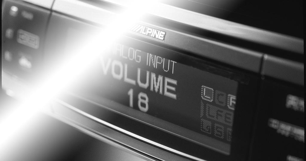
16 Basic Operation,, VOL VOL MODE Using with RCA-type or optical cable connections (non Ai-NET connections) Adjusting the volume, fader, balance and subwoofer After determining the input level, adjust the volume, fader, balance and subwoofer from the PXA-H900. Be careful not to make these adjustments on the head unit. 1 Adjusting the volume Use the VOL and VOL buttons to adjust the volume (from 0 to 35). ANALOG INPUT VOLUME 12 L R 12-EN
17 1 2 Adjusting the fader and balance Press the MODE button and select the mode to be adjusted. Sub Wf. BALANCE FADER Use the and buttons or the and buttons within 5 seconds to adjust to the desired level. BALANCE: Press the or button to adjust the balance of the volume between the left and right speakers (from L15 to R15). ANALOG INPUT BALANCE R3 L R FADER: Press the or button to adjust the balance of the volume between the front and back speakers (from F15 to R15). ANALOG INPUT FADER F5 L R 1 Adjusting the subwoofer Press the MODE button for at least 2 seconds to turn the Sub Wf. setting to ON. Sub Wf. ON Sub Wf. OFF 2 Press the MODE button and select Sub Wf.. Sub Wf. BALANCE FADER 3 Press the or button within 5 seconds to adjust to the desired level (from 0 to +15). ANALOG INPUT SubWf. +12 L R 13-EN
18 Automatic Adjustments Preparations for automatic adjustments The PXA-H900 is equipped with two automatic adjustment functions: Adaptive Equalizer and Precision Automated Time Correction. The preparations described below must be made in order to perform these automatic adjustments. After making these preparations, refer to Automatic adjustments (Adaptive Equalizer) (page 16) and Performing time correction automatically (Precision Automated Time Correction) (page 20) to perform the respective automatic adjustments Check that the defeat mode is off. (See page 53.) Adjust the head unit and amplifier levels. Head unit: Set the balance and fader to center. Front, rear and center amplifiers: Set the amp gains to center or normal to start. If there are no rear speakers, check that the rear speakers are turned off. (See page 8.) Gain levels may be changed if you are not satisfied with the automatic results. Make the gain changes and return the automatic adjustment. Subwoofer amplifier: Set the amplifier gain to center or normal. If the subwoofer is located in the trunk or a remote place (for example at the very back of a station wagon), adjust the subwoofer to increase the volume several steps. Speaker Crossovers: Set the crossovers for all the speakers in the system that will require them. See page 32, Crossover adjustment, for more information on setting the crossovers. Connect the included microphone to the PXA- H900. Refer to the Installation manual. The adjustment differs according to the position of the microphone. Search for the position at which the desired sound quality can be achieved. We recommend using speaker boxes or box locations that produce low levels of indirect sound (for example, sealed boxes or vented boxes with the vents firing into the trunk). The proper adjustments cannot be achieved if the subwoofer is located in the trunk and the trunk and cabin are separated by a metal sheet. Either move the subwoofer into the cabin or open a hole in the rear tray to join the two spaces. (This is not necessary if the partition is not a metal sheet.) If the partition is a metal sheet, open a hole in the rear tray. If you encounter a problem, consult your authorized dealer. Is the partition a metal sheet? Or move the subwoofer into the cabin. Do not disconnect the microphone during the automatic adjustment procedure. 14-EN
19 4 Secure the microphone in place. Failure to fix the microphone securely in place may result in distortion or improper acoustic positioning. The microphone must be mounted very securely so the bass frequencies will not vibrate it. For example, the microphone could be wedged between the headrest and the seat. If the microphone is placed on a tripod, the microphone must be very securely mounted to the tripod (not loosely clamped). The tripod must also be very securely weighted and/or strapped so it cannot move. The microphone would usually be placed near the driver s ear position. However, since the Adaptive Equalizer is adjusting low frequencies, the microphone does not need to be at the exact ear position, it is more important that it is securely mounted. Hints for making the Adaptive Equalizer adjustments To achieve the desired acoustic image, we recommend fastening the microphone to the four points described below. (The figures are approximates. Adjust them according to the vehicle.) A Ceiling directly above the listening position (driver s seat position sharp sound) B 20 cm (7-7/8") in front of above position (driver s seat position softer sound than above, bass sound positioned toward front) C 20 cm (7-7/8") further in front of above position (driver s seat position even softer sound, bass sound positioned further toward front) D Base of rearview mirror (position for both driver s and passenger s seats) The acoustic positioning changes according to the position of the microphone because the human ear senses the distance from the sound s focal position. Adjust according to your personal tastes. D C 40cm(15-3/4") B 20cm(7-7/8") A 0 15-EN
20 Automatic Adjustments, VOL VOL AUTO AEQ Automatic adjustments (Adaptive Equalizer) Use this function to automatically perform frequency, phase and time correction. Adjustments for the acoustic properties specific to the vehicle s interior are made to achieve the ideal acoustic space. 1 2 Before starting the automatic adjustment procedure, park the vehicle in a quiet place to avoid the effects of external sounds. Set the vehicle s key to the ACC position. Do not start the engine. The vibrations may make it impossible to achieve the proper adjustment values. Preparations must be made before performing the automatic adjustment procedure. Refer to page 14. The adjustments differ according to the position of the microphone. We recommend performing the operation repeatedly with the microphone in different positions. After each operation, store the settings. Compare the sound at the different setting and from different locations. Select the one you prefer. The Adaptive Equalizer eliminates or reduces the boomy bass peaks common to the car cabin. Elimination of the peaks uncovers the lower bass information which was masked before. However, because your ear and brain are used to those peaks, the subwoofers may sound less loud. You must listen for a few weeks to allow your ears and brain to recalibrate and become used to the flat sound. 16-EN
21 3 4 5 Adjust the volume. When using RCA-type connections, use the PXA-H900 s VOL and VOL buttons to display 5 (on the PXA-H900 s display). When using Ai-NET connections, perform the head unit s volume operation to display 5 (on the head unit s display). When the CDA-7990 is combined as a head unit, adjust to 50dB. Press the AUTO AEQ button. Press the or button to select the channel or speaker environment for outputting the correction signals. FRONT.ON SubWf. ON FRONT.ON SubWf. OFF FRONT.OFF SubWf. ON AUTO ADAPTIVE EQ F RONT. ON SUbW. ON PUSH [ ENTER] TO START L R The Adaptive Equalizer flattens the overall bass response, both the SPL and the phase. Depending on how noisy your vehicle is, a flat SPL response may cause low bass notes to be masked by road noise. In such cases, use the conventional EQ features of the PXA-H900 to gently tilt up the low bass response. Again, listen for a few weeks to allow your ears and brain to recalibrate and become used to the flat sound. After the automatic adjustments are performed, the sound from the different speakers arrives at the listening position at virtually the same time. If you are accustomed to delays in the bass sound (which is common with conventional systems), the sound may seem somewhat strange to you. If so, increase the subwoofer delay time slightly to achieve sound closer to that of home audio systems. Heavy bass speakers do not reproduce medium low frequencies (150 to 400 Hz) well (the sound tends to be distorted). When using such speakers, lower the subwoofer s cutoff frequency. If the volume of the subwoofer is too low after the automatic adjustment procedure is performed, the adjustments have not been performed properly. Refer to step 2 under Preparations for automatic adjustments and perform the adjustments again. Depending on the speaker settings (on or off), certain speakers may not be displayed (in which case they cannot be set). next page 17-EN
22 Automatic Adjustments AUTO AEQ ENTER 6 Press the ENTER button to set the automatic adjustment mode, then leave the vehicle. To cancel, press the AUTO AEQ button. The automatic adjustment procedure consists of the operations described below and requires 2 to 8 minutes to be completed. Perform the time correction. Perform the acoustic response measurement. Perform the frequency response and phase response corrections. ADJUSTMENTS ARE COMPLETED is displayed for about 5 seconds and the automatic adjustment mode is canceled. Strong sounds (about 90 db) are produced during the automatic adjustment procedure. These sounds can be heard outside the vehicle. Be sure to park the vehicle in a place where the sound will not be a nuisance. The time required to perform the adjustments depends on the speaker connections. The frequency response and phase response corrections are only applied to the front and subwoofer channels. Time correction is applied to all channels. If processing is interrupted after time correction is completed, time correction is set to the adjusted value. If the microphone does not pick up the sound or the speakers are not working or are connected or wired improperly, the automatic adjustments are not performed and a warning message is displayed. Check the various speakers then perform the automatic adjustments again. Example of warning message NOTICE PLEASE CHECK AMPLIFIER GAIN AND CONNECTIONS 18-EN
23 7 Check that the automatic adjustments have been completed (that ADJUSTMENTS ARE COM- PLETED has been displayed for 5 seconds), get back in the vehicle, then disconnect the microphone. Note that using for extended periods of time without turning on the engine may wear down the battery. 8 To store the settings, refer to Storing settings in the memory (page 52). Turning the adjusted settings off The adjusted settings can be turned off. Doing so clears the settings, so we recommend storing them in the memory before turning them off. 1) Press the AUTO AEQ button. 2) Press the button. 3) Press the ENTER button. 19-EN
24 Automatic Adjustments AUTO TCR VOL VOL Performing time correction automatically (Precision Automated Time Correction) Due to the particular conditions inside the vehicle, there is a major difference between the distances of the various speakers and the listening position. This function uses the included measurement microphone to automatically measure and analyze the distances between the speakers and the listening position and perform the optimum time correction. 1 Before starting the automatic adjustment procedure, park the vehicle in a quiet place to avoid the effects of external sounds. Preparations must be made before performing the automatic adjustment procedure. Refer to page 14. The PXA-H900 s automatic adjustments take into account the delay time between the time at which the signals are input to the speakers until the sound is output. This does not correspond to the actual distance. With the automatic adjustments, the average delay time within the speakers playable frequency range is measured. Measurements may not be possible when using special speakers or in special playback environments. If this is the case, perform the adjustments manually. 2 Set the vehicle s key to the ACC position. Do not start the engine. The vibrations may make it impossible to achieve the proper adjustment values. 20-EN
25 3 Adjust the volume. When using RCA-type connections, use the PXA-H900 s VOL and VOL buttons to display 5 (on the PXA-H900 s display). When using Ai-NET connections, perform the head unit s volume operation to display 5 (on the head unit s display). When the CDA-7990 is combined as a head unit, adjust to 50dB. 4 Press the AUTO TCR button. AUTO TIME CORRECTION PUSH [ ENTER] TO START L R next page 21-EN
26 Automatic Adjustments ENTER AUTO TCR 5 Press the ENTER button to set the automatic adjustment mode, then leave the vehicle. To cancel, press the AUTO TCR button. The automatic adjustment procedure consists of the operations described below and requires about 2 minutes to be completed. Perform the time correction. ADJUSTMENTS ARE COMPLETED is displayed for about 5 seconds and the automatic adjustment mode is canceled. Strong sounds (about 90 db) are produced during the automatic adjustment procedure. These sounds can be heard outside the vehicle. Be sure to park the vehicle in a place where the sound will not be a nuisance. If the microphone does not pick up the sound or the speakers are not working or are connected or wired improperly, the automatic adjustments are not performed and a warning message is displayed. Check the various speakers then perform the automatic adjustments again. Example of warning message NOTICE PLEASE CHECK AMPLIFIER GAIN AND CONNECTIONS 22-EN
27 6 Check that the automatic adjustments have been completed (that ADJUSTMENTS ARE COM- PLETED has been displayed for 5 seconds), get back in the vehicle, then disconnect the microphone. Note that using for extended periods of time without turning on the engine may wear down the battery. 7 To store the settings, refer to Storing settings in the memory (page 52). 23-EN
28 Settings/Adjustments Performing time correction manually (Time Correction) Though sufficient correction can be achieved with the Adaptive Equalizer and Precision Automated Time Correction automatic adjustments, it is also possible for the user to calculate the correction values and make the adjustments manually. This manual adjustment requires sufficient knowledge and experience, however, so we suggest you have it performed at your store of purchase. 1 Check that the defeat mode is off. (See page 53.) When the microphone is connected, the sound in the car is input through the microphone and displayed on the spectrum analyzer. This display can be used as reference when making the adjustment. For details of the spectrum analyzer display, see Switching the display mode (page 53). This adjustment is easier when test signals such as pink noise are used. For information on test signals, consult your store of purchase. 2 Sit in the listening position (the driver s seat, for example) and measure the distance (in meters) between your head and the various speakers. 3 Calculate the difference in distance between the farthest speaker and the other speakers. L = (distance of farthest speaker) (distance of other speakers) 4 Divide the distances calculated for the different speakers by the speed of sound (340 m/s temperature 14 C). This value is the time correction value for the different speakers. The speed of sound fluctuates according to the temperature. The accurate speed of sound can be achieved with the formula shown below. Speed of sound = C x T C: T: Temperature ( C) 24-EN
29 Concrete examples 1. Calculating the time correction value for the front left speaker on the diagram below. Conditions: Distance between farthest speaker and listening position: 2.25 m (88-3/4") Distance between front left speaker and listening position: 0.5 m (20") Calculation: L = 2.25 m (88-3/4") 0.5 m (20") = 1.75 m (68-3/4") Compensation time = x 1000 = 5.1 (ms) In other words, setting the time correction value for the front left speaker to 5.1 (ms) sets a virtual distance matching the distance to the farthest speaker. 5.1ms 0.5m (20") 2.25m (88-3/4") The sound is uneven because the distance between the listening position and the different speakers is different. The difference in the distance between the front left and rear right speakers is 1.75 meters (68-3/4"). Time correction eliminates the difference between the time required for the sound from the different speakers to reach the listening position. Setting the time correction of the front left speaker to 5.1 ms makes it possible to coordinate the distance from the listening position to the speaker. next page 25-EN
30 Settings/Adjustments,, TCR ch UP ch DN ENTER 5 6 Press the TCR button to set the time correction mode. Press the ch UP or ch DN button to select the desired channel. FLLOW FRLOW FLMID FRMID FLHIGH FRHIGH Sub Wf.R Sub Wf.L CENTER REAR R REAR L 7 Press the or button to adjust the time correction value. TCR FRLOW 5.1[ms] ( [ inch ]/ 173 [ cm] ) L EVEL : 0 [db] L R Displayed distance The values indicated for inch and cm are the distance calculated from the time. (340 m/s temperature 14 C, 1 inch is calculated as 2.54 cm.) In reality the time difference depends not only on the difference in physical distance but also on the delay time between the time at which the signals are input to the speakers until the sound is output. This delay time depends on the speaker, and may also be somewhat affected on how the speaker is mounted on the vehicle. After making the setting, we recommend listening to the sound and fine-adjusting if necessary. 26-EN
31 8 Press the or button to adjust the speaker output level. The level can be set to OFF or adjusted between 12 and 0. 9 Press the ENTER button to complete the setting. 27-EN
32 Settings/Adjustments,, DISPLAY ON/OFF ch UP GEQ ch DN ENTER Equalizer adjustments The level of the front, rear and center channels can be adjusted separately for 31 bands and the subwoofer can be adjusted for 10 bands (a total of 175 bands) to achieve the desired sound field Check that the defeat mode is off. (See page 53.) Press the GEQ button. Press the ch UP or ch DN button to select the desired channel. FRONT REAR CENTER Sub Wf. When the microphone is connected, the sound in the car is input through the microphone and displayed on the spectrum analyzer. This display can be used as reference when making the adjustment. For details of the spectrum analyzer display, see Switching the display mode (page 53). This adjustment is easier when test signals such as pink noise are used. For information on test signals, consult your store of purchase. Even more subtle adjustments can be used using a computer. For details, consult your store of purchase. Check the playable frequency ranges of the connected speakers before making the equalizer adjustments. If the speaker s playable frequency range is 55 Hz to 30 khz, for example, adjusting the 40 Hz or 20 Hz band has no effect. Additionally, you may overload and damage the speakers. 28-EN
33 4 Press the or button so that the frequency band is flashing. Adjustable frequency bands FRONT / REAR / CENTER : 20 Hz to 20 khz (in 1/3 octave steps) Sub Wf. : 20 Hz to 160 Hz (in 1/3 octave steps) GEQ F RONT 50.0[Hz ] 0[dB] L R When adjusted with the Adaptive Equalizer When adjusted with FRONT. ON for the Adaptive Equalizer adjustment, frequencies of 500 Hz and below GEQ FRONT cannot be adjusted. When adjusted with Sub Wf. ON for the Adaptive Equalizer adjustment, GEQ Sub Wf. cannot be adjusted. 5 Press the or button to adjust to the desired level (between ±9 db in 1 db steps). Repeat the above operation to adjust other frequency bands. GEQ F RONT 50.0[Hz ] + 5[dB] L R 6 Press the ENTER button to complete the setting. Once the settings have been made, we recommend storing them in the memory. See page 52 for instructions. Real time analyzer When the microphone included with the PXA-H900 is connected, the sounds inside the vehicle are input through the microphone and displayed on the spectrum analyzer display. 1) With the microphone connected, press the DISPLAY ON/ OFF button and select the spectrum analyzer display mode. Operation display Spectrum analyzer display Display off For details, refer to Switching the display mode (page 53). Real time analyzer This is a function for displaying the microphone input signals or input signals on the spectrum analyzer display. This allows the signal properties or the acoustic properties inside the vehicle (amplitude) to be measured even without special equipment. When microphone connected: Spectrum analyzer display of acoustic properties inside the vehicle When microphone not connected: Spectrum analyzer display of input signals 29-EN
34 Settings/Adjustments Crossover network The PXA-H900 is equipped with an active dividing network allowing the bands to be split before amplification by the power amplifier. Because of this, there is no need for a passive network between the speakers and amplifiers and the amplifiers are fully independent, thus eliminating the problem of interference and making it possible to achieve the optimum acoustic space by dividing the playback frequencies in a way suited to the capacities of the speakers. This adjustment requires sufficient knowledge and experience. If you have problems, so we suggest you have the adjustment made by your store of purchase. Adjust the high pass filter (H.P.F.) and low pass filter (L.P.F.) and set the slope (filter response attenuation slope) for the different bands. Make the adjustments according to the playable frequency ranges and frequency responses of the connected speakers. Cutoff frequency adjustment range (1/6 octave steps) Slope adjustment H.P.F. L.P.F. H.P.F. L.P.F. FLOW (Front low range speaker) 20Hz 18kHz 22.5Hz 20kHz -6/-12/-18/-24/-30dB/ Filter OFF -6/-12/-18/-24/-30dB/ Filter OFF FMID (Front mid range speaker) 20Hz 18kHz 22.5Hz 20kHz -6/-12/-18/-24/-30dB/ Filter OFF -6/-12/-18/-24/-30dB/ Filter OFF FHIGH (Front high range speaker) 1kHz 18kHz 1.1kHz 20kHz -6/-12/-18/-24/-30dB -6/-12/-18/-24/-30dB/ Filter OFF REAR (Rear speaker) 20Hz 18kHz 22.5Hz 20kHz -6/-12/-18/-24/-30dB/ Filter OFF -6/-12/-18/-24/-30dB/ Filter OFF CENTER (Center speaker) 20Hz 18kHz 22.5Hz 20kHz -6/-12/-18/-24/-30dB/ Filter OFF -6/-12/-18/-24/-30dB/ Filter OFF Sub Wf. (Subwoofer) 20Hz 180Hz 22.5Hz 200Hz -6/-12/-18/-24/-30dB/ Filter OFF -6/-12/-18/-24/-30dB 30-EN
35 Output signals with these frequencies Slope adjustment Slope off 20Hz H.P.F. cutoff frequency L.P.F. cutoff frequency 10kHz The H.P.F. setting cannot be the same as or exceed the L.P.F. setting for that channel. The crossover network is a filter that divides specific frequency bands. The high pass filter is a filter that cuts frequencies below a certain frequency (bass frequencies) and lets through treble frequencies. The low pass filter is a filter that cuts frequencies above a certain frequency (treble frequencies) and lets through bass frequencies. The slope is a value expressing the attenuation of the signal in decibels when the frequency is increased or decreased by one octave. The higher the slope value, the steeper the slope. If the slope is set to OFF, the signal does not pass through the filter, so there is no effect. In order to protect the speakers, the front high range high pass filter cannot be turned off (the slope cannot be set to OFF ). For the same reason, the subwoofer low pass filter cannot be turned off (the slope cannot be set to OFF ). Tweeters may be damaged if low frequency signals are input to them. 31-EN
36 Settings/Adjustments,, TCR DIV ch UP ch DN ENTER Crossover adjustment Check that the defeat mode is off. (See page 53.) Press the DIV button to set the divider adjustment mode. Press the ch UP or ch DN button to select the channel (speaker) to be adjusted. If the Adaptive Equalizer adjustment has been performed, adjusting FLOW or Sub Wf. has no effect since this is no longer the Adaptive Equalizer DIV setting. A caution message appears on the screen. Press the ENTER button to continue the adjustment, ch UP or ch DN button to cancel it. FLOW FMID FHIGH REAR CENTER Sub Wf. 4 Press the or button to select the crossover H.P.F. or L.P.F. band. The selected band flashes. DIV FM ID 400[Hz ] OFF L R 32-EN
37 5 Press the or button to select the desired cutoff frequency (crossover point). The bands that can be adjusted differ according to the channel (speaker). 6 Adjust the slope by pressing the DIV button. Repeat steps 3 to 6 to adjust the crossover point/ slope for other channels. The selected slope flashes. DIV FM ID 280[Hz ] 12[dB/oct] L R 7 Press the ENTER button to complete the setting. Hint for adjusting the subwoofer If the subwoofer is installed on the rear deck, setting a gentle L.P.F. slope (for example 6 db/oct.) makes the sound localization more to the rear. This can also affect the acoustic localization of the front. Hints for adjusting the high range Depending on the speaker, inputting low frequency component signals (about 2 khz or less) with the H.P.F. adjustment could result in distortion. If so, set a steep slope (for example 36 db/oct.). When doing so, adjust so that the mid and high range sounds do not separate. Normally use with the L.P.F. off. If the high range is too strong, we recommend adjusting for a gentle slope. After making the settings, we recommend storing them in the memory. See page 52 for instructions. Listen to the sound of the various speakers and adjust the levels if the balance is poor. Adjusting the speaker output level 1) Press the TCR button. 2) Press the ch UP or ch DN button to select the desired speaker. 3) Press the or button to adjust the speaker output level. The level can be set to OFF or adjusted between 12 and 0. 4) Press the ENTER button. Hint for adjusting the low range When a subwoofer is connected and you are using a speaker with a low range of under 10 or 12 cm (3-15/16" or 4-3/4"), setting the low range H.P.F. to OFF can result in distortion when low frequency components are input. If so, set the H.P.F. slope to a value suited for the speaker s frequency response. 33-EN
38 Settings/Adjustments,, ch UP ch DN PHASE Switching the phase The phase of the different speakers can be switched. Set to the phase at which the sound from the speakers is clearest. It is also possible to switch the subwoofer between stereo and monaural. 1 Check that the defeat mode is off. (See page 53.) 2 Press the PHASE button. 3 Press the ch UP or ch DN button to select the desired channel. FLOW FMID FHIGH REAR CENTER Sub Wf. 34-EN
39 4 Press the or button to switch the phase PHASE F LOW 180[deg] L R Switching the subwoofer between stereo and monaural 1) At step 3 above, select Sub Wf.. 2) Press the or button to switch between ST (stereo) and MONO (monaural). ST MONO 35-EN
40 Using Dolby Surround PL / REAR FILL Using the Pro Logic mode With the PXA-H900, Pro Logic processing can be conducted on the music signals recorded on two channels to achieve Dolby Pro Logic surround sound. For two-channel Dolby Digital, DTS and MPEG2 signals, there is also a REAR FILL function for outputting the signals of the front channel to the rear channel. 1 Press the PL/REAR FILL button to select the desired mode. DOLBY PROLOGIC REAR FILL OFF DOLBY DIGITAL DOLBY PL / REAR FILL DOLBY PROLOGIC L S R This function only works with two-channel signals. This operation cannot be performed when 5.1-channel DTS or Dolby Digital signals are input. REAR FILL function Depending on the input signals, the sound may only be output from the front speakers. In this case, the REAR FILL function can be used to output signals from the rear speakers as well. Once the settings are made, we recommend storing them in the memory. See page 52 for instructions. When the REAR FILL mode is turned on, sound may be produced from the rear speakers even if the rear speakers are set to OFF. Do not use the REAR FILL function if you do not want to output sound from the rear speakers. The HDCD decode mode cannot be used in the DOLBY PROLOGIC mode. 36-EN
41 Adjustment procedure for Dolby Surround Make the adjustments described below in order to reproduce Dolby Digital and DTS sound with greater accuracy. Adjustment procedure 1 Speaker setup (page 38) (Turning the speakers to be used on and off and setting their response) 2 Adjusting the speaker levels (page 40) (Adjusting the signal output level to the various speakers) 3 Center/rear speaker time correction (pages 42 and 44) (Adjusting the signal output time compensation (timing) of the various speakers) 4 Adjusting the acoustic image (page 46) (Adjusting the acoustic image to achieve a sound as if the center speaker were directly in front of the listener) 5 Mixing bass sound to the rear channel (page 48) (Achieving smooth sound in the rear seat by mixing the front audio signals with the rear speaker signals) 6 Achieving powerful high volume sound (page 50) (Achieving energetic sound with even greater power, like the sound in a movie theater) 7 Storing settings in the memory (page 52) (Storing all the settings and adjustments made on the PXA-H900 (not only the above settings/adjusts) in the memory) Note: In case of combining the Automatic adjustments etc. We recommend to make the Automatic adjustments before the Dolby Surround adjustments. 37-EN
42 Using Dolby Surround,, 5.1 ch SETUP ENTER Speaker setup The PXA-H900 can be set according to the playable frequency range of your speakers. Check the playable frequency range of the speakers (not including the subwoofer) before performing this operation to verify whether the speakers can play low frequencies (of about 80 Hz or less). 1 Press the 5.1ch SETUP button. This function can be set in the Pro Logic, DTS, MPEG and Dolby Digital modes. Avoid stopping, pausing, switching the disc, cueing, fastforwarding or switching the audio channel of the player while making this adjustment. The setting is canceled if the decode mode is switched. 2 Press the or button and select SPEAKER SETUP. SPEAKER SETUP REAR DELAY SETUP OUTPUTLEVEL SETUP CENTER DELAY SETUP BI-PHANTOM SETUP REAR-MIX SETUP 3 Press the ENTER button. 38-EN
43 4 5 Press the or button and select the speakers to be set. FRONT CENTER REAR Press the or button and select the speaker response. SMALL LARGE *2 * OFF 1 SMALL: When a speaker that cannot play low frequencies (80 Hz or less) is connected LARGE: When a speaker that can play low frequencies (80 Hz or less) is connected OFF: When no speaker is connected If the center speaker is turned OFF, the center channel s audio signals are added to the audio signals output from the front speakers. If you set the speaker response to OFF, also set the speaker level adjustment (speaker setting) to OFF. (See page 8.) *1 It is not possible to set the front speakers to OFF. *2 If the front speakers are set to SMALL, the rear and center speakers cannot be set to LARGE. Perform the setup for the all the speakers ( FRONT, CENTER and REAR ). If not, the sound may not be balanced. DOLBY DIGITAL SPEAKER SETUP FRONT LARGE L C R LFE Ls Rs 6 Press the 5.1ch SETUP button to complete the setting. To perform other setup operations, press the ENTER button to display the setup menu. Once the settings are made, we recommend storing them in the memory. See page 52 for instructions. 39-EN
44 Using Dolby Surround, 5.1 ch SETUP ch UP ch DN ENTER Adjusting the speaker levels Use the test tones output from the PXA-H900 to adjust so that the volume of the different speakers is equal. To achieve a strong sense of presence, adjust so that the volume of the sound heard from the different speakers at the listening position is the same. 1 Press the 5.1ch SETUP button. This function can be set in the Pro Logic, DTS, MPEG and Dolby Digital modes. Avoid stopping, pausing, switching the disc, cueing, fastforwarding or switching the audio channel of the player while making this adjustment. The setting is canceled if the decode mode is switched. 2 Press the or button and select OUTPUT LEVEL SETUP. SPEAKER SETUP OUTPUTLEVEL SETUP BI-PHANTOM SETUP* REAR DELAY SETUP* CENTER DELAY SETUP* REAR-MIX SETUP* * Not displayed when the rear/center speaker setting is set to OFF. 3 Press the ENTER button. Test tones are output from the various speaker channels in order for about 2 seconds each. L (left front) C (center) R (right front) If a speaker is set to the off mode, that speaker s level cannot be adjusted. Refer to Speaker setup (page 38). LS (left surround) RS (right surround) 40-EN
45 4 While the test tones are being produced from the speakers, press the or button to adjust so that the volume of the different speakers is equal. The level of the different speakers can be adjusted within a range of ±10 db. Adjust based on the front speakers. TEST NOISE OUTPUTLEVEL SETUP FRONT L +2 L Adjusting with the speaker fixed 1) Press the ch UP or ch DN button to select the speaker to be adjusted. 2) Press the or button to adjust the volume. 3) Repeat steps 1) and 2) to adjust, then press the ENTER button. 4) To complete the adjustment, press the 5.1ch SETUP button. 5 Press the 5.1ch SETUP button to complete the adjustment. To perform other setup operations, press the ENTER button to display the setup menu. Once the settings are made, we recommend storing them in the memory. See page 52 for instructions. 41-EN
46 Using Dolby Surround, 5.1 ch SETUP ENTER Center speaker time correction Use this function after adjusting the delay time of the different speakers with the Adaptive Equalizer, Precision Automated Time Correction and automatic/manual time compensation functions. Using this function results in sound with a sense of presence. 1 Press the 5.1ch SETUP button. This function can be set in the Pro Logic, DTS, MPEG and Dolby Digital modes. Avoid stopping, pausing, switching the disc, cueing, fastforwarding or switching the audio channel of the player while making this adjustment. The setting is canceled if the decode mode is switched. 2 Press the or button and select CENTER DELAY SETUP. SPEAKER SETUP REAR DELAY SETUP* OUTPUTLEVEL SETUP CENTER DELAY SETUP* BI-PHANTOM SETUP* REAR-MIX SETUP* * Not displayed when the rear/center speaker setting is set to OFF. (See page 38.) 42-EN
47 3 Press the ENTER button. 4 5 Press the or button to adjust the time correction value. The center delay setting can be adjusted within the range of 0 to 5 ms. DOLBY DG I ITAL CENTER DELAY SETUP 3 L C R LFE Ls Rs Press the 5.1ch SETUP button to complete the adjustment. To perform other setup operations, press the ENTER button to display the setup menu. This adjustment cannot be performed when the center speaker setup setting is set to OFF. If the distance of the front speaker is shorter than or the same as that of the center speaker, set to 0. If the distance of the front speaker is longer, set to 1 to 5. Once the settings are made, we recommend storing them in the memory. See page 52 for instructions. 43-EN
48 Using Dolby Surround, 5.1 ch SETUP ENTER Rear speaker time correction Perform this function after adjusting the delay time of the various speakers. Adding this time correction to the values adjusted with the Adaptive Equalizer, Precision Automated Time Correction and automatic/manual time compensation functions gives the sound a sense of expansion. 1 Press the 5.1ch SETUP button. This function can be set in the Pro Logic, DTS, MPEG and Dolby Digital modes. Avoid stopping, pausing, switching the disc, cueing, fastforwarding or switching the audio channel of the player while making this adjustment. The setting is canceled if the decode mode is switched. 2 Press the or button and select REAR DELAY SETUP. SPEAKER SETUP REAR DELAY SETUP* OUTPUTLEVEL SETUP CENTER DELAY SETUP* BI-PHANTOM SETUP* REAR-MIX SETUP* * Not displayed when the rear/center speaker setting is set to OFF. (See page 38.) 3 Press the ENTER button. 44-EN
49 4 5 Press the or button to adjust the time correction value. When the Pro Logic mode is off: 0: 0ms, 1: 5ms, 2: 10ms, 3: 15ms When the Pro Logic mode is on: 0: 15ms, 1: 20ms, 2: 25ms, 3: 30ms DOLBY DG I ITAL REAR DELAY SETUP 3 L C R LFE Ls Rs Press the 5.1ch SETUP button to complete the adjustment. To perform other setup operations, press the ENTER button to display the setup menu. This adjustment cannot be performed when the rear speaker mode setting is set to OFF. If the distance of the front speaker is shorter than or the same as that of the center speaker, set to 0. If the distance of the front speaker is longer, set to 1 to 3. Once the settings are made, we recommend storing them in the memory. See page 52 for instructions. 45-EN
50 Using Dolby Surround,, 5.1 ch SETUP ENTER Adjusting the acoustic image To achieve sound with a sense of presence, the center speaker must be placed directly in front of the listening position. With this function, the center channel information is distributed to the left and right speakers. This creates an acoustic images simulating a center speaker directly in front of the listener. 1 Press the 5.1ch SETUP button. This function can be set in the Pro Logic, DTS, MPEG and Dolby Digital modes. Avoid stopping, pausing, switching the disc, cueing, fastforwarding or switching the audio channel of the player while making this adjustment. The setting is canceled if the decode mode is switched. 2 Press the or button and select BI-PHANTOM SETUP. SPEAKER SETUP OUTPUTLEVEL SETUP BI-PHANTOM SETUP* REAR DELAY SETUP* CENTER DELAY SETUP* REAR-MIX SETUP* * Not displayed when the rear/center speaker setting is set to OFF. (See page 38.) 3 Press the ENTER button. 46-EN
51 4 5 Press the or button to select ON. 0 OFF (ON) Press the or button to adjust the level. The level can be adjusted within the range of 5 to +5. The higher the level, the more the position of the center speaker is shifted to the sides. This adjustment cannot be performed when the center speaker setup setting is set to OFF. The off mode is set automatically when the center speaker setup setting is set to OFF. DOLBY DG I ITAL BI PHANTOM SETUP + 3 L C R LFE Ls Rs 6 Press the 5.1ch SETUP button to complete the adjustment. To perform other setup operations, press the ENTER button to display the setup menu. Once the settings are made, we recommend storing them in the memory. See page 52 for instructions. 47-EN
52 Using Dolby Surround,, 5.1 ch SETUP ENTER Mixing bass sound to the rear channel This function mixes the front channel audio signals to the audio signals output from the rear speakers, improving the sound in the vehicle s rear seat. 1 Press the 5.1ch SETUP button. This function can be set in the Pro Logic, DTS, MPEG and Dolby Digital modes. Avoid stopping, pausing, switching the disc, cueing, fastforwarding or switching the audio channel of the player while making this adjustment. The setting is canceled if the decode mode is switched. 2 Press the or button and select REAR-MIX SETUP. SPEAKER SETUP REAR DELAY SETUP* OUTPUTLEVEL SETUP CENTER DELAY SETUP* BI-PHANTOM SETUP* REAR-MIX SETUP* * Not displayed when the rear/center speaker setting is set to OFF. (See page 38.) 3 Press the ENTER button. 48-EN
53 4 5 Press the or button to select ON. 0 OFF (ON) Press the or button to adjust the level. The level can be set to one of five positions: 6, 3, 0, +3, and +6. The higher the level, the more the bass sound output from the rear speakers. (The effect differs according to the software (DVD, etc.).) This adjustment cannot be performed when the rear speaker setup setting is set to OFF. The off mode is set automatically when the rear speaker setup setting is set to OFF. When the REAR-MIX function is turned ON, sound may be produced from the rear speakers even if the rear speakers are set to OFF. If you do not want sound to be produced from the rear speakers, turn the REAR-MIX mode OFF. If the REAR-MIX adjustment is performed when the REAR FILL function is on, during the 2-channel decode mode the REAR FILL function is given priority, so the sound does not change as adjusted with the REAR-MIX function. DOLBY DIGITAL REAR MIX SETUP +3 L C R LFE Ls Rs 6 Press the 5.1ch SETUP button to complete the adjustment. To perform other setup operations, press the ENTER button to display the setup menu. Once the settings are made, we recommend storing them in the memory. See page 52 for instructions. 49-EN
OWNER S MANUAL MOTORIZED 7 WIDE TFT LCD COLOR MONITOR CNT-701
 OWNER S MANUAL PW MOTORIZED 7 WIDE TFT LCD COLOR MONITOR CNT-701 ANY CHANGES OR MODIFICATIONS IN CONSTRUCTION OF THIS UNIT DEVICE WHICH IS NOT APPROVED BY THE PARTY RESPONSIBLE FOR COMPLIACE COULD VOID
DIGITAL SPEAKER MANAGEMENT UK
 DSM2-6mkII DIGITAL SPEAKER MANAGEMENT 170.659UK Features 96kHz sampling frequency, 32-bit A/D and D/A converter, 24-bit DSP processor Input channel: 6-band parametric EQ, Delay, Polarity Output channel:
VMA573 and VMA or 7 Wide Screen Color LCD Monitor. Owner s Manual. Installation Guide
 VMA573 and VMA773 5.6 or 7 Wide Screen Color LCD Monitor Owner s Manual Installation Guide 7 headrest / stand alone wide monitor 5.6 headrest / stand alone wide monitor 2 WARINING! The Clarion VMA 573
SB60 airsound BASE USER S GUIDE. version 1.0
 SB60 airsound BASE USER S GUIDE version.0 CONTENTS WELCOME PACKAGE CONTENTS The AirSOUND BASE SB60 AirSOUND BASE Controls & Indicators GETING STARTED 4 Remote control Sound Source / Setting memory FRONT
RX-6000VBK / RX-6008VBK
 MENU ENTER STANDBY SOURCE NAME SOURCE NAME THEATER LIVE CLUB DANCE CLUB HALL PAVILLION ON DIGITAL AUTO D I G I T A L ADJUST SETTING MEMORY AUDIO/VIDEO CONTROL RECEIVER RX-6000VBK / RX-6008VBK SLEEP POWER
VMA ACTIVE MATRIX TFT COLOR LCD MONITOR OWNER S MANUAL INSTALLATION GUIDE
 VMA6491 6.4 ACTIVE MATRIX TFT COLOR LCD MONITOR OWNER S MANUAL INSTALLATION GUIDE OWNER S MANUAL WARNING! THE CLARION VMA6491 LCD MONITOR IS DESIGNED FOR REAR SEAT PASSENGER VIEWING ONLY. THIS PRODUCT
Features/Specifications
 Introduction Thank you for purchasing the DD Audio DSI-1(Digital Signal Integrator). The DSI-1 is a feature rich audio signal processor that will allow you to precisely tune the acoustics of your car audio
SIR-GM1 GM CLASS-2 BUS COMPATIBLE SIRIUS SATELLITE RADIO TUNER
 SIR-GM1 GM CLASS-2 BUS COMPATIBLE SIRIUS SATELLITE RADIO TUNER Installation Guide Congratulations on your purchase of the SIR-GM1 the GM Compatible SIRIUS Satellite Radio Tuner! Your SIR-GM1 is designed
TABLE OF CONTENTS Bass Bass Bass Bass Bass Bass Bass
 MaxxBass TABLE OF CONTENTS Congratulations.......................................2 Service..............................................2 Caution.............................................2 Why Use MaxxBass..................................3
XO-231 USER S MANUAL. Crossover ENGLISH
 XO-231 Crossover ENGLISH USER S MANUAL IMPORTANT SAFETY INSTRUCTIONS For your own safety you should read this section in full first! Risk of electrical shock! Connect the device only to a properly wired
FM/AM Cassette Car Stereo
 3-862-775-31 (1) FM/AM Cassette Car Stereo Operating Instructions For installation and connections, see the supplied installation/connections manual. XR-1807 1998 by Sony Corporation Features General Detachable-front
SOURCE COMMANDER MSS433 A/V SELECTOR OWNER S MANUAL INSTALLATION GUIDE
 SOURCE COMMANDER MSS433 R L V R L V R L V R L V M U L T I S T A T I O N A/V SELECTOR OWNER S MANUAL INSTALLATION GUIDE OWNER S MANUAL/INSTALLATION GUIDE WARNING! THE CLARION MSS433 MULTISTATION A/V SELECTOR
QUICKSTART GUIDE ENGLISH ( 1 4 ) GUÍA DE INICIO RÁPIDO ESPAÑOL ( 5 8 ) GUIDE D UTILISATION SIMPLIFIÉ FRANÇAIS ( 9 12 )
 GUÍA DE INICIO RÁPIDO ESPAÑOL ( 5 8 ) GUIDE D UTILISATION SIMPLIFIÉ FRANÇAIS ( 9 12 )") PROFESSIONAL 3-CHANNEL SCRATCH MIXER QUICKSTART GUIDE ENGLISH ( 1 4 ) GUÍA DE INICIO RÁPIDO ESPAÑOL ( 5 8 ) GUIDE D UTILISATION SIMPLIFIÉ FRANÇAIS ( 9 12 ) GUIDA RAPIDA ITALIANO ( 13 16 ) KURZANLEITUNG
PROFESSIONAL 3-CHANNEL SCRATCH MIXER QUICKSTART GUIDE ENGLISH ( 1 4 ) GUÍA DE INICIO RÁPIDO ESPAÑOL ( 5 8 ) GUIDE D UTILISATION SIMPLIFIÉ FRANÇAIS ( 9 12 ) GUIDA RAPIDA ITALIANO ( 13 16 ) KURZANLEITUNG
2.0 Wall Mount TV Soundbar Instruction Manual
 8010275 2.0 Wall Mount TV Soundbar Instruction Manual Read all of the instructions before using this soundbar and keep the manual in a safe place for future reference. Safety Information CA UT IO N RISK
Subwoofers ENGLISH FRANCAIS SPANISH DEUTSCH OWNER S MANUEL MODE D EMPLOI MANUEL DEL USUARIO BEDIENUNGSANLEITUNG
 ENGLISH FRANCAIS SPANISH DEUTSCH Subwoofers OWNER S MANUEL MODE D EMPLOI MANUEL DEL USUARIO BEDIENUNGSANLEITUNG Titan 5.6 Titan 7.6 MK2 Titan 11.6 MK2 Titan 15.6 MK2 MOSSCADE BP 306-94709 Maisons-Alfort
Q-TV2. User Manual. for Screens
 Q-TV2 User Manual for 30-42 Screens Contents Introduction 02 Safety Guidelines 03 Getting started 03 Potential Uses 04 Carton Contents 05 Q-TV2 Controls 05 Remote Fixings 06 Fixing Rails 07 Fitting Q-TV2
INSTRUCTIONS e
 OPERATING INSTRUCTIONS e11 022771 Headrest 7.0" 16:9 Color Display Monitor Important Notice It is unlawful in most jurisdictions for a person to drive a motor vehicle which is equipped with a television
PLAYMATE PROFESSIONAL STEREO 19 MIXER, USB/SD CARD AND BLUETOOTH PLAYER. User Guide and Reference Manual. page 1
 PLAYMATE PROFESSIONAL STEREO 19 MIXER, USB/SD CARD AND BLUETOOTH PLAYER User Guide and Reference Manual page 1 INTRODUCTION Congratulations and thank you for purchasing the NewHank Playmate mixer. This
METHODS TO ELIMINATE THE BASS CANCELLATION BETWEEN LFE AND MAIN CHANNELS
 METHODS TO ELIMINATE THE BASS CANCELLATION BETWEEN LFE AND MAIN CHANNELS SHINTARO HOSOI 1, MICK M. SAWAGUCHI 2, AND NOBUO KAMEYAMA 3 1 Speaker Engineering Department, Pioneer Corporation, Tokyo, Japan
FD Trinitron Colour Television
 R 4-205-569-32(1) FD Trinitron Television Instruction Manual GB KV-14LM1U 2000 by Sony Corporation NOTICE FOR CUSTOMERS IN THE UNITED KINGDOM A moulded plug complying with BS1363 is fitted to this equipment
CPH-10 SUBWOOFER OWNERS MANUAL
 CPH-10 SUBWOOFER OWNERS MANUAL www.artcoustic.com Welcome to the world of Artcoustic! Congratulations with your purchase of the Artcoustic CPH-10 Subwoofer. The CPH-10 has an efficient design, producing
MODEL PA-2 AUDIOPATH ENHANCHER (1998-MSRP $399.00)
") F O R T H E L O V E O F M U S I C MODEL PA-2 AUDIOPATH ENHANCHER (1998-MSRP $399.00) OPERATION INSTALLATION MANUAL INTRODUCTION After countless hours of analyzing the performance of existing car audio
F O R T H E L O V E O F M U S I C MODEL PA-2 AUDIOPATH ENHANCHER (1998-MSRP $399.00) OPERATION INSTALLATION MANUAL INTRODUCTION After countless hours of analyzing the performance of existing car audio
CDM10: Channel USB Mixer. Item ref: UK User Manual
 CDM10:4 19 4 Channel USB Mixer Item ref: 171.135UK User Manual Caution: Please read this manual carefully before operating Damage caused by misuse is not covered by the warranty Introduction Thank you
DCX-24 ORDERCODE D2020
 DCX-24 ORDERCODE D2020 Congratulations! You have bought a great, innovative product from DAP Audio. The DAP Audio DCX-24 brings excitement to any venue. Whether you want simple plug-&-play action or a
RX-E111RSL / RX-E112RSL
 VCR /REW TV/VIDEO SLEEP DIMMER RM-SRXE111R REMOTE HOME CINEMA CENTER TV DIRECT STB VCR TV ANALOG/DIGITAL TAPE FM INPUT ON/OFF PTY( MODE STB RETURN PTY SEARCH ENTER VCR FM MODE TA/NEWS/INFO AUDIO CENTER
TV CHANNEL INSTALLATION
 LCD TV TV CHANNEL ATION Immediately after unpacking and plugging in your new television, run the auto program function to set up the TV for the broadcast or cable channels available in your area. If you
MULTI CHANNEL AV RECEIVERSTR-DH750/STR- DH550
 MULTI CHANNEL AV RECEIVERSTR-DH750/STR- DH550 PROTECTOR The receiver will automatically turn off after a few seconds. Check the followings: There may be an electrical surge or power failure. Unplug the
BM5 mkiii Owner s manual
 BM5 mkiii Owner s manual Introduction Introduction Important safety instructions The lightning flash with an arrowhead symbol within an equilateral triangle, is intended to alert the user to the presence
CM4-BT. Compact Mixer with Bluetooth UK User Manual
 CM4-BT Compact Mixer with Bluetooth 170.804UK User Manual Caution: Please read this manual carefully before operating Damage caused by misuse is not covered by the warranty Introduction: Thank you for
UNFOLD THE BASE. Quick Start Guide CONTENTS INSTALLING LCD TV ON THE WALL
 Quick Start Guide English CONTENTS INSTALLING LCD TV ON THE WALL.. UNFOLD THE BASE............... TV CHANNEL INSTALLATION........ PRESENTATION OF THE LCD TV..... ACCESSORIES.................... BATTERY
ORPHEUS ZERO U S E R M A N U A L
 ORPHEUS ZERO U S E R M A N U A L I N T R O D U C T I O N FEATURES Class 1 product CD drive (ORPHEUS ZERO Drive) or player (ORPHEUS ZERO Player) Multiple formats reader : CD, CD-R, CD-RW Software controlled
DSP 18 Sub active subwoofer. user manual
 DSP 18 Sub active subwoofer user manual Musikhaus Thomann Thomann GmbH Hans-Thomann-Straße 1 96138 Burgebrach Germany Telephone: +49 (0) 9546 9223-0 E-mail: info@thomann.de Internet: www.thomann.de 05.11.2018,
CR-6 MIXER USER MANUAL ENGLISH. Order Code: MIXE01
 CR-6 MIXER P R O F E S S I O N A L 1 9 R A C K M I X E R Order Code: MIXE01 w w w. p r o l i g h t. c o. u k USER MANUAL ENGLISH WARNING FOR YOUR OWN SAFETY, PLEASE READ THIS USER MANUAL CAREFULLY BEFORE
SATRI AMPLIFIER AMP-51R. Owner s Manual
 SATRI AMPLIFIER AMP-51R Owner s Manual contents SAFETY INSTRUCTIONS 4 INTRODUCTION 6 OVERVIEW (FRONT PANEL) 8 OVERVIEW (REAR PANEL) 9 OVERVIEW (REMOTE CONTROL) 1 1 OPERATION 12 TROUBLESHOOTING 13 SPECIFICATION
TS2.8 Sub OWNER S MANUAL
 TS2.8 Sub OWNER S MANUAL TS2.8 Sub CONTENTS IMPORTANT SAFETY INSTRUCTIONS 03 WARNINGS 03 FUSE PROTECTION 04 WARNING: STRONG MAGNETIC FIELD 04 EMC / EMI 04 ECODESIGN STANDBY POWER CONSUMPTION 04 WARRANTY
Achat 115 Sub A active subwoofer. user manual
 Achat 115 Sub A active subwoofer user manual Musikhaus Thomann Thomann GmbH Hans-Thomann-Straße 1 96138 Burgebrach Deutschland Telephone: +49 (0) 9546 9223-0 E-mail: info@thomann.de Internet: www.thomann.de
MODEL PA II-R (1995-MSRP $549.00)
") F O R T H E L O V E O F M U S I C MODEL PA II-R (1995-MSRP $549.00) OWNER'S MANUAL AND INSTALLATION GUIDE INTRODUCTION To aid in the exciting and custom installs which installers are performing all over
F O R T H E L O V E O F M U S I C MODEL PA II-R (1995-MSRP $549.00) OWNER'S MANUAL AND INSTALLATION GUIDE INTRODUCTION To aid in the exciting and custom installs which installers are performing all over
English. User Manual sub8 Subwoofer SUBWOOFER. Supporting your digital lifestyle
 English User Manual sub8 Subwoofer U SUBWOOFER Supporting your digital lifestyle Table of Contents Important Safety Precautions........ 2 Introduction / What s in the Box?...... 3 Front & Rear Panels............
Content. 1. Important Your home theatre 05 -Main unit- Front -Main unit- Back -Remote
 1 Content 1. Important 04 2. Your home theatre 05 -Main unit- Front -Main unit- Back -Remote 3. Home theatre set up 07 - Connect to the TV - Connect audio from TV and other devices 4. Subwoofer and Speaker
After Ref.No:
 Ref.No:171.130 Safety Instructions 1. Read Instructions-All the safety and operating instructions should be read before this product is operated. 2. Retain Instruction- The safety and operating instruction
SOUNDSTREAM. Parametric Equalizer. Owner's Manual and Installation Guide
 SOUNDSTREAM Parametric Equalizer Owner's Manual and Installation Guide 1. CONGRATULATIONS Congratulations for buying this Sound Stream product and thank you for your confidence! With this Sound Stream
CAUTION RISK OF ELECTRIC SHOCK NO NOT OPEN
 Evolution Digital HD Set-Top Box Important Safety Instructions 1. Read these instructions. 2. Keep these instructions. 3. Heed all warnings. 4. Follow all instructions. 5. Do not use this apparatus near
GIULIA Y. combo amplifier for acoustic instruments
 GIULIA Y combo amplifier for acoustic instruments IMPORTANT SAFETY INSTRUCTIONS THE LIGHTNING FLASH WITH ARROWHEAD SYMBOL, WITHIN AN EQUILATERAL TRIANGLE, IS INTENDED TO ALERT THE USER TO THE PRESENCE
SW 50. Powered Subwoofer with Built-in Stereo Crossover
 Owner s Manual SW 50 ed Subwoofer with Built-in Stereo Crossover Congratulations on your new purchase and welcome to the AudioSource family of satisfied customers. We trust you will continue to enjoy the
DVH-1019 MK2 User Manual PULL
 DVH-1019 MK2 User Manual PULL Safety Rules WARNING Read all instructions. Failure to follow all instructions listed below may result in electric shock, fire and/or serious injury. The term electrical device,as
Safety Information. Camera System. If you back up while looking only at the monitor, you may cause damage or injury. Always back up slowly.
 Table of Contents Introduction...3 Safety Information...4-6 Before Beginning Installation...7 Installation Guide...8 Wiring Camera & Monitor...9-10 Replacement Installation Diagram...11 Clip-On Installation
FM/AM Cassette Car Stereo
 3-858-377-11 (2) FM/AM Cassette Car Stereo Operating Instructions For installation and connections, see the supplied installation/connections manual. XR-1947 1996 by Sony Corporation 2 Welcome! Thank you
MANUAL DE INICIO RÁPIDO ESPAÑOL ( 7 10 ) GUIDE D UTILISATION RAPIDE FRANÇAIS ( ) MANUALE RAPIDO DI UTILIZZAZIONE ITALIANO ( )
 GUIDE D UTILISATION RAPIDE FRANÇAIS ( ) MANUALE RAPIDO DI UTILIZZAZIONE ITALIANO ( )") QUICKSTART GUIDE ENGLISH ( 6 ) MANUAL DE INICIO RÁPIDO ESPAÑOL ( ) GUIDE D UTILISATION RAPIDE FRANÇAIS ( 4 ) MANUALE RAPIDO DI UTILIZZAZIONE ITALIANO ( 5 ) KURZANLEITUNG DEUTSCH ( 22 ) INTRODUCTION Welcome
QUICKSTART GUIDE ENGLISH ( 6 ) MANUAL DE INICIO RÁPIDO ESPAÑOL ( ) GUIDE D UTILISATION RAPIDE FRANÇAIS ( 4 ) MANUALE RAPIDO DI UTILIZZAZIONE ITALIANO ( 5 ) KURZANLEITUNG DEUTSCH ( 22 ) INTRODUCTION Welcome
Evolution Digital HD Set-Top Box Important Safety Instructions
 Evolution Digital HD Set-Top Box Important Safety Instructions 1. Read these instructions. 2. Keep these instructions. 3. Heed all warnings. 4. Follow all instructions. 5. Do not use this apparatus near
HD Digital Set-Top Box Quick Start Guide
 HD Digital Set-Top Box Quick Start Guide Eagle Communications HD Digital Set-Top Box Important Safety Instructions WARNING TO REDUCE THE RISK OF FIRE OR ELECTRIC SHOCK, DO NOT EXPOSE THIS PRODUCT TO RAIN
Table of contents. Opening the Overhead Monitor... 4 Precautions Care And Maintenance... 5 Operating OHM102/153 Monitor...
 Warning! The Clarion OHM102/OHM153 overhead monitor systems are designed for strictly for rear seat entertainment. Viewing the monitor while operating a motor vehicle can result in serious injury and/or
28 4K LED monitor. User Manual M284K
 28 4K LED monitor User Manual M284K CONTENTS Safety Information... 2 What s included..... 4 Getting Started....... 8 Troubleshooting.... 14 Specification.... 15 2 of 15 SAFETY INFORMATION Read these instructions
Passive Four Channel Stereo/Mono Mixer/Splitter. Artcessories. User's Manual
 Passive Four Channel Stereo/Mono Mixer/Splitter Artcessories User's Manual IMPORTANT SAFETY INSTRUCTION READ FIRST This symbol, whenever it appears, alerts you to the presence of uninsulated dangerous
PROFESSIONAL 2-CHANNEL MIXER WITH EFFECTS LOOP
 PROFESSIONAL 2-CHANNEL MIXER WITH EFFECTS LOOP QUICKSTART GUIDE ENGLISH ( 1 4 ) GUÍA DE INICIO RÁPIDO ESPAÑOL ( 5 8 ) GUIDE D UTILISATION SIMPLIFIÉ FRANÇAIS ( 9 12 ) GUIDA RAPIDA ITALIANO ( 13 16 ) KURZANLEITUNG
DP1 DYNAMIC PROCESSOR MODULE OPERATING INSTRUCTIONS
 DP1 DYNAMIC PROCESSOR MODULE OPERATING INSTRUCTIONS and trouble-shooting guide LECTROSONICS, INC. Rio Rancho, NM INTRODUCTION The DP1 Dynamic Processor Module provides complete dynamic control of signals
IMPORTANT SAFETY INSTRUCTIONS
 IMPORTANT SAFETY INSTRUCTIONS 1. Read, follow and keep these instructions safely. 2. Heed all warnings. 1. Do not use this apparatus near water. 2. Clean only with dry cloth. 3. Do not block any ventilation
USER MANUAL GOLDMUND MIMESIS 32.5 Universal Acoustic Processor
 USER MANUAL GOLDMUND MIMESIS 32.5 Universal Acoustic Processor Congratulations. Thank you for purchasing the Goldmund MIMESIS 32.5 UNIVERSAL ACOUSTIC PROCESSOR. You have acquired the best multi-usage acoustic
OPERATIONS MANUAL FOR EDISON PROFESSIONAL Professional ABS Molded Loudspeaker M4000
 M4000 Introduction: Congratulations on your purchase of an M-4000 powered loudspeaker, engineered and manufactured by BriteLite Enterprises. The M-4000 includes a high-output compression driver, and 15
M R X
 MRX 710 / 510 / 310 AWARD-WINNING A/V RECEIVERS ANTHEM ROOM CORRECTION SYSTEM A fantastic-sounding product well worthy of a serious audition don t delay. ~ What Hi Fi on the MRX 700 MRX 710 shown Among
ESC333. simple setup guide
 TM ESC333 simple setup guide thank you for choosing JBL. For more than 50 years, JBL has been involved in every aspect of music and film recording and reproduction, from live performances to the recordings
Location and function of controls
 Location and function of controls 1. Motor Control Selector 9. DC INPUT SOCKET 2. PAUSE Key 10. DIN Socket 3. STOP/EJECT Key 11. RECORD Indicator (Yellow) 4. FAST FORWARD/CUE Key 12. DATA Indicator (Green)
CMX-DSP Compact Mixers
 CMX-DSP Compact Mixers CMX4-DSP, CMX8-DSP, CMX12-DSP Introduction Thank you for choosing a Pulse CMX-DSP series mixer. This product has been designed to offer reliable, high quality mixing for stage and/or
AG 500SC. Owners Manual. Manual Version 1.7
 AG 500SC Owners Manual Manual Version 1.7 1. Table of Contents I. Getting Started page 3. A. Safety Instructions B. Manual Conventions C. Basic Setup D. Protection Modes II. Features and Functions page
Video SystemVideo System
 PublishedPublished: May 4, 2005 Video SystemVideo System Video System Component Location ItemItem Part NumberPart Number 1 - Television tuner module 2 - Rear seat entertainment control module 3 - DVD (digital
MANUAL ENGLISH Core Club Ordercode: D2314
 MANUAL ENGLISH Core Club Ordercode: Highlite International B.V. Vestastraat 2 6468 EX Kerkrade the Netherlands Table of contents Warning... 2 Unpacking Instructions... 2 Safety Instructions... 2 Operating
MODEL AVP1/APV1P DOLBY DIGITAL DTS PROCESSOR/PREAMPLIFIER OWNERS MANUAL
 MODEL AVP1/APV1P DOLBY DIGITAL DTS PROCESSOR/PREAMPLIFIER OWNERS MANUAL AVP1/ AVP1P OWNERS MANUAL INTRODUCTION Congratulations on your PERREAUX Model AVP1 purchase. To realise the full potential of your
Using the oscillator
 Using the oscillator Here s how to send a sine wave or pink noise from the internal oscillator to a desired bus. In the function access area, press the MON- ITOR button to access the MONITOR screen. In
Advanced Return Path Alignment & Maintenance Using the 9581 SST R4
 Advanced Return Path Alignment & Maintenance Using Introduction The first step in developing a successful alignment and maintenance strategy for the return path depends on understanding what constitutes
TF5 / TF3 / TF1 DIGITAL MIXING CONSOLE. TF StageMix User's Guide
 TF5 / TF3 / TF1 DIGITAL MIXING CONSOLE EN Note The software and this document are the exclusive copyrights of Yamaha Corporation. Copying or modifying the software or reproduction of this document, by
USER MANUAL MX102 & MX1202
 USER MANUAL MX102 & MX1202 WWW.PULSE-AUDIO.CO.UK 1 SAVE THESE SAFETY INSTRUCTIONS Thank you for purchasing our product. To assure the optimum performance, please read this manual carefully and keep it
OWNER S MANUAL EVOLUTION SERIES POWERED SUBWOOFER ES-SUB-EVO6-100
 OWNER S MANUAL EVOLUTION SERIES POWERED SUBWOOFER ES-SUB-EVO6-100 Important Safety Instructions CAUTION RISK OF ELECTRIC SHOCK! DO NOT OPEN! ATTENTION! RISQUE DE CHOC! ÉLECTRIQUE PAS OUVRIR! The lightning
AcoustiSoft RPlusD ver
 AcoustiSoft RPlusD ver 1.2.03 Feb 20 2007 Doug Plumb doug@etfacoustic.com http://www.etfacoustic.com/rplusdsite/index.html Software Overview RPlusD is designed to provide all necessary function to both
XB-14 Quick Operation Manual V1 23/10/2013
 XB-14 Quick Operation Manual V1 23/10/2013 14. MIXER ON/OFF SWITCH 19. USB GAIN CONTROL 17. ST1 18. ST16 SELECTOR SELECTOR 7. GAIN CONTROL 6. 100Hz HIGH PASS FILTER 13. MAIN 16. GAIN 5. EQ METERS 12. PHANTOM
AIR CONDITIONING AND AUDIO SECTION 2. Automatic air conditioning controls Audio system... 85
 SECTION 2 Automatic air conditioning controls.......................... 80 Audio system............................................. 85 79 AUTOMATIC AIR CONDITIONING CONTROLS Air intake control button
A Straightforward One-Seat Stereo Tuning Process and Some Notes About Why it Works
 A Straightforward One-Seat Stereo Tuning Process and Some Notes About Why it Works The Process Note 1: This process assumes the input to your DSP is confirmed as a flat, two-channel and in phase signal,
Noise Detector ND-1 Operating Manual
 Noise Detector ND-1 Operating Manual SPECTRADYNAMICS, INC 1849 Cherry St. Unit 2 Louisville, CO 80027 Phone: (303) 665-1852 Fax: (303) 604-6088 Table of Contents ND-1 Description...... 3 Safety and Preparation
OWNERS MANUAL LUNATEC V3 MICROPHONE PREAMPLIFIER AND A/D CONVERTER
 OWNERS MANUAL LUNATEC V3 MICROPHONE PREAMPLIFIER AND A/D CONVERTER LUNATEC 35 +48 35 +48 30 40 30 40 0 25 45 25 45 3 192 1 1 6 176.4 20 50 20 50 9 96 12 PEAK 88.2 55 55 RESET 48 10 60 2 10 60 2 21 44.1
Owner s Manual. TFT-LCD TV High Brightness & Contrast NICAM/A2 Stereo Sound MODEL: L15SV6-A0, L17LV6-A1,L20AV6-A0 L17L6A-G1,L20L6A
 TFT-LCD COLOUR TV Owner s Manual TFT-LCD TV High Brightness & Contrast NICAM/A2 Stereo Sound Please read this manual carefully before using your television and keep this manual in a good place for future
User s Guide - 64 Bit Digital Electronic Crossover
 CHANNEL D Pure Music User s Guide - 64 Bit Digital Electronic Crossover Contents Copyright 2006, 2007, 2008, 2009, 2010, 2011 Channel D http://www.channel-d.com CHANNEL D Crossover Pure Music s Crossover
THERMIONIC CULTURE. TheEarlybird 2.2. valve microphone pre-amplifier OPERATING MANUAL
 THERMIONIC CULTURE TheEarlybird 2.2 valve microphone pre-amplifier OPERATING MANUAL WARNING For your personal safety, please read this operating manual and warning thoroughly before using the equipment.
clipping; yellow LED lights when limiting action occurs. Input Section Features
 ELX-1A Rack-Mount Mic/Line Mixer Four inputs, one output in a single rack space Very-highery-high-quality audio performance High reliability Extensive filtering circuitry and shielding protect against
Owner s Manual. VL9000 Series HEADREST MONITOR SYSTEM
 VL9000 Series HEADREST MONITOR SYSTEM Copyright 2003 TMI Products, Inc. All Rights Reserved Corona, CA U.S.A. 060300 Owner s Manual 1493 Bentley Drive Corona, CA 92879 909-272-1996 800-624-7960 Fax 909-272-1584
VDH910 PLAYER / RECORDER OWNER S MANUAL INSTALLATION GUIDE
 VDH910 V I D E O C A S S E T T E PLAYER / RECORDER OWNER S MANUAL INSTALLATION GUIDE OWNER S MANUAL/INSTALLATION GUIDE WARNING! THE CLARION VDH910 MOBILE MULTIMEDIA VCR IS DESIGNED FOR REAR SEAT VIEWING
TDM 24CX-2 24CX-3 24CX-4 ELECTRONIC CROSSOVER OWNER S MANUAL A U D I O
 TDM A U D I O 24CX-2 24CX-3 24CX-4 ELECTRONIC CROSSOVER OWNER S MANUAL TDM AUDIO INC. 7270 BELLAIRE AVE. NORTH HOLLYWOOD, CA 91605 (818) 765-6200 TDMAUDIO.COM IMPORTANT! *** Read Before Using *** CAUTION:
VITEK VTM-TLM191 VTM-TLM240
 VTM-TLM191 VTM-TLM240 19 & 24 Professional LED Monitors with HDMI, VGA, and Looping BNC VITEK FEATURES 19 & 24 Wide Screen LED Display Panel HDMI, VGA, and Looping BNC Composite Video Inputs & Stereo Audio
Electric Motorized Projection Screen Spectrum Tab-Tension Series User s Guide
 Electric Motorized Projection Screen Spectrum Tab-Tension Series User s Guide Important Safety Precautions Make sure to read this user s guide and follow the procedures below prior to screen operation.
Ambient Temperature...3 Electromagnetic Compliance...3
 TABLE OF CONTENTS: SAFETY AND SERVICE... 2 Operational Safety... 2 Location... 2 Ambient Temperature...3 Electromagnetic Compliance...3 Service... 3 Cleaning... 3 Package Contents... 4 Specifications...
RX-V357. AV Receiver Ampli-tuner audio-vidéo
 G RX-V357 AV Receiver Ampli-tuner audio-vidéo OWNER S MANUAL MODE D EMPLOI BEDIENUNGSANLEITUNG BRUKSANVISNING GEBRUIKSAANWIJZING ИНСТРУКЦИЯ ПО ЭКСПЛУАТАЦИИ CAUTION: READ THIS BEFORE OPERATING YOUR UNIT.
SC-C1M SiriusConnect TM Vehicle Tuner
 SC-C1M SiriusConnect TM Vehicle Tuner For Special Market Applications Installation Guide Congratulations on the Purchase of your new SIRIUS SC-C1 SiriusConnect TM Vehicle Tuner. The SC-C1M is packaged
Remote Control. degraded, causing unreliable operation. The recommended effective distance for remote operation is about 16 feet (5 meters).
.") Media Streaming Sound Bar RTS736W User Manual Remote Control using the remote control Point the remote control at the REMOTE SENSOR located on the unit (see Front Panel illustration for precise location).
Media Streaming Sound Bar RTS736W User Manual Remote Control using the remote control Point the remote control at the REMOTE SENSOR located on the unit (see Front Panel illustration for precise location).
Concert Series ORDERCODE D3470 ORDERCODE D3471 ORDERCODE D3472 D3470 D3471 D3472
 Concert Series ORDERCODE D3470 ORDERCODE D3471 ORDERCODE D3472 D3470 D3471 D3472 Congratulations! You have bought a great, innovative product from DAP Audio. The DAP Audio Concert Series brings excitement
NJU26125 Application Note PEQ Adjustment Procedure Manual New Japan Radio Co., Ltd
 NJU26125 Application Note PEQ Adjustment Procedure Manual New Japan Radio Co., Ltd Version 1.00 CONTENTS 1.ABSTRACT...2 2.NJU26125 FIRMWARE BLOCK DIAGRAM...2 3.EQUIPMENT...2 4.ATTENTION...2 5.GENERAL FLOW
X D M PREAMP MIXER
 User Instructions X D M - 3 5 2 PREAMP MIXER Thank you for purchasing this American DJ product. The XDM-352 is ready to be used, there is no assembly required. Please read the following instructions before
RX-V596RDS. Natural Sound AV Receiver Ampli-tuner audio-vidéo
 G B RX-V596RDS Natural Sound AV Receiver Ampli-tuner audio-vidéo OWNER S MANUAL MODE D EMPLOI BEDIENUNGSANLEITUNG BRUKSANVISNING MANUALE DI ISTRUZIONI MANUAL DE INSTRUCCIONES GEBRUIKSAANWIJZING CAUTION:
NS-B750. Speaker Enceinte OWNER S MANUAL MODE D EMPLOI BEDIENUNGSANLEITUNG MANUAL DE INSTRUCCIONES
 TG Speaker Enceinte OWNER S MANUAL MODE D EMPLOI BEDIENUNGSANLEITUNG MANUAL DE INSTRUCCIONES PRECAUTIONS Read this before using the speaker. To assure the finest performance, please read this manual carefully.
STAGE 250. Owner s Manual TRANSPORTABLE PA WITH BUILT-IN MIXER AND 24 BIT EFFECTS
 STAGE 250 Owner s Manual TRANSPORTABLE PA WITH BUILT-IN MIXER AND 24 BIT EFFECTS Important Safety Instructions For your own safety you must read this section in full first! Intended use This device is
TOUR SERIES LOUDSPEAKER SYSTEMS
 TOUR SERIES LOUDSPEAKER SYSTEMS From Fender Pro Audio Owner's Manual for 2912(c), 2915(c) P/N 050757 Fender Musical Instruments 7975 North Hayden Road, Scottsdale, Arizona 85258 U.S.A. Fender knows the
Winmate Communication INC.
 20.1 Military Grade Display Model: R20L100-RKA2ML User s Manual Winmate Communication INC. May, 2011 1 IMPORTANT SAFETY INSTRUCTIONS Please read these instructions carefully before using the product and
SX7 e l e c t r o n i c c r o s s o v e r
 electronic crossover 1999 anzar Audio Inc owner s manual troubleshooting If you experience Electronic crossover does not turn on Check that: emote Turn-On wire has 12V 12V wire has 12V Ground wire is properly
!! 1 of! 21. Magico Subwoofer Setup and DSP Control Manual. Password: Fact_ory
 Magico Subwoofer Setup and DSP Control Manual Password: Fact_ory Thank you for the purchase of your new Magico S-Sub or Q-Sub. The goal of this setup manual is to first integrate the subwoofer into your