Entron Controls, LLC S. Batesville Road Greer, SC Phone: fax: Rev 1.
|
|
|
- Maryann Hensley
- 5 years ago
- Views:
Transcription


1 Entron Controls, LLC S. Batesville Road Greer, SC Phone: fax: Rev 1.0
2 Important Safety Instructions READ THIS MANUAL COMPLETELY BEFORE ATTEMPTING TO INSTALL OR OPERATE THE CONTROL. STORE THIS TECHNICAL INFORMATION IN A PLACE TO WHICH ALL USERS HAVE ACCESS AT ANY TIME ENTRON Controls follows the practices of the RWMA for precautionary labeling. See RWMA Bulletins #1 and #5 for a complete description. Observe the WARNING, DANGER, and CAUTION labels affixed to control to maintain safe operation. ENTRON Controls, LLC. and its affiliates are not responsible for any harm caused by non-compliance of instructions associated with the aforementioned labels or signal words to follow. The signal word DANGER is used to call attention to immediate or imminent hazards which if not avoided will result in immediate, serious, or personal injury or loss of life. Examples are: exposed high voltage; exposed fan blades. The signal word WARNING is used to call attention to potential hazards which could result in personal injury or loss of life. Examples are: not using proper personal protection; removal of guards. The signal word CAUTION is used to call attention to hazards which could result in non-life threatening personal injury or damage to equipment. CAUTION may also be used to alert against unsafe practices. The term NOTICE is used for making recommendations on use, supplementary information, or helpful suggestions. Non-compliance with these recommendations may result in damage to control, welding machine, or workpiece. ENTRON Controls, LLC. and its affiliates are not responsible for damage caused by such non-compliance, and warranties may be voided accordingly at the discretion of ENTRON Controls. WARNING: Individuals with cardiac devices should maintain a safe distance due to strong magnetic fields arising from resistance welding. The function of cardiac pacemakers and defibrillators may be disturbed, which may cause death or considerable health damages to persons concerned! These persons should avoid the welding system unless authorized by a licensed physician Rev 1.0
3 My Control Information Filling out the following information (and keeping it readily available) may allow for future technical service of equipment to be conducted more efficiently: Model #: Serial #: OEM/Distributer: Contact #: Purchase Date: EN6001 Hardware Connections P1 2, Foot Switch #1 P1 3, Foot Switch #2 P1 4, Emergency Stop P1 5, No Weld Signal P1 6, Programmable Input #1 P1 7, Programmable Input #2 P1 8, Programmable Input #3 P1 9, Programmable Input #4 P1 10, Programmable Input #5 P1 11, Programmable Input #6 P2 2, Solenoid Valve #1 P2 3, Solenoid Valve #2 P2 4, Solenoid Valve #3 P2 5, Programmable Output #1 P2 6, Programmable Output #2 P2 7, Programmable Output #3 P2 8, Programmable Output #4 P3 Sensing Coil Not Used Primary Secondary Rev 1.0
4 Weld Schedule Worksheet Filling out the following information (and keeping it readily available) may allow for future technical service of equipment to be conducted more efficiently. Please duplicate and complete this page for each utilized schedule: SCHEDULE #: Squeeze Delay: cycles KVA or % Squeeze: cycles Valves: Weld 1: cycles KVA or % Cool 1: cycles Slope: cycles Weld 2: cycles KVA or % Cool 2: cycles Impulses: cycles Hold: cycles : Cycle Mode: cycles Comments: Tap Setting: Pressure: Machine: Rev 1.0
5 Table of Contents Functions... 6 Specifications Wiring Diagrams Menu Navigation... 9 Saving Weld Schedules Loading Weld Schedules Updating Firmware. 12 User Connections. 13 Weld Timing Cycles.. 14 Programming Parameters List.. 15 I/O Map.. 22 Error List.. 23 Warranty and Service Policy Rev 1.0
6 Functions Constant current regulation Primary or Secondary feedback Current Monitoring with high, low, and pre-limits Up to 64 programs (internal or external selection) On Timer Membrane Keyboard with backlit 128x64 (8 lines) LCD graphic display Six (6) inputs and four (4) outputs with output protection on CPU Electrode management functions; including stepping, current counting, tip-dressing, and preset curves Welding programs may be linked together for complex spot schedules (chained or successive) USB-capable firmware refresh AC 60/50 Hz welding support Spot / Pulsation / Seam welding / Flash or Butt welding / Brazing Multiple weld intervals plus pulsation, upslope and downslope Air-over-oil gun operation Water Saver (contactor timer) Head lock function Program lockout (key switch) function Operation mode switch (program lockout and Weld/No Weld) Error reset switch Optional plug-in Ethernet card provides PLC compatibility with Modbus and EtherNet/IP Rev 1.0
7 Specifications Environmental Conditions: Operating Temperature 0 C to 60 C Storage/Transport Temperature -25 C to 70 C Air pressure 0 to 2000m above sea level Humidity no dew point excursion allowed Enclosure Ratings NEMA 1 and NEMA 12 Electronics Ratings: CPU operating voltage (without I/O) 24 VDC +5% at 220 ma Rated current (without I/O) at 24V SV1-SV3: ~500 ma PO1-PO4: ~500 ma Discrete I/O: Input +24V +15% DC Output 24 VDC, 0.5A max AC Output 120 VAC, 1A max Supply I/O: 24 VDC +5% Rev 1.0
8 Wiring and Connectivity Rev 1.0
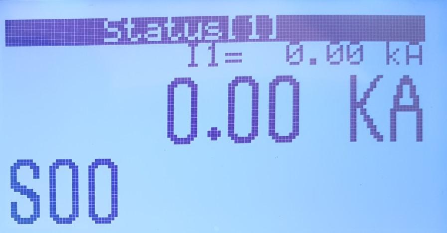
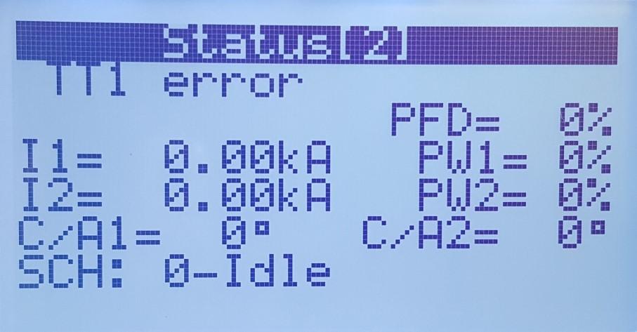
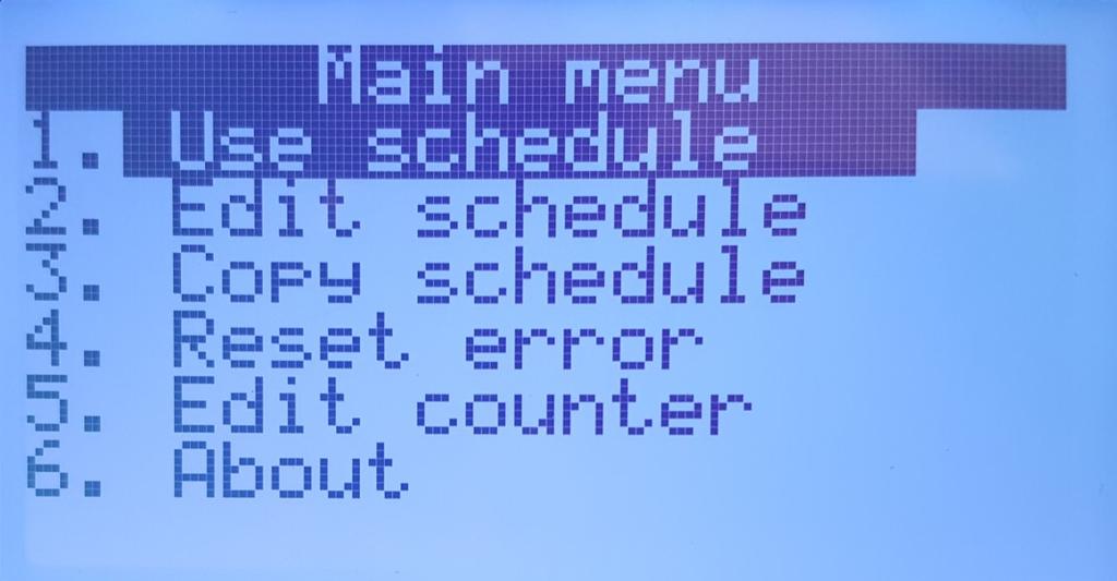

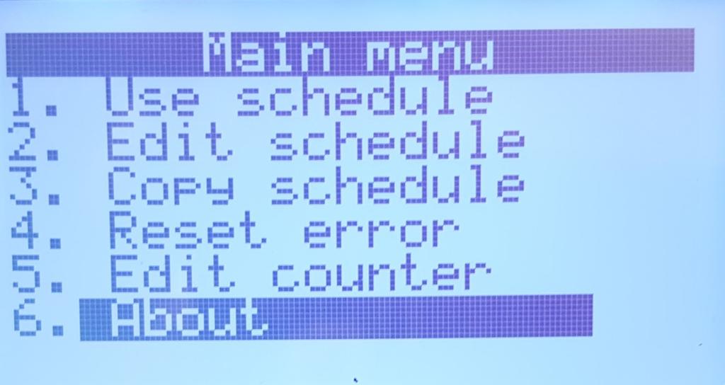

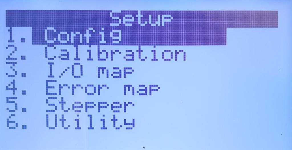
9 Menu Navigation Status Page List (Default) Main Menu Schedule Select 1. Use Schedule 2. Edit Schedule 3. Copy Schedule 4. Reset Error 5. Edit counter 6. About AND Setup Menu Rev 1.0

 using")

10 Saving Weld Schedules Step 1: Insert a formatted USB drive into USB port on the control panel Step 2: From the Setup Menu (see Menu Navigation for details) select Utility. Step 3: Select Backup data Step 4: Rename file (desired) using and Step 5: Set Confirm to YES using and Step 6: Press and verify that DONE!!! appears in the top left corner of the title bar Rev 1.0
 select Utility.")
11 Loading Weld Schedules Step 1: Insert USB drive with a previously saved backup file* into the USB port on the control panel. Step 2: From the Setup Menu (see Menu Navigation for details) select Utility. Step 3: Select Restore data Step 4: Select the desired filename* using Step 5: Set Confirm to YES using and and Step 6: Press and verify that DONE!!! appears in the top left corner of the title bar. *Note: The backup file must be on the root directory of the USB drive. And the filename must be EN EN6 to EN EN Rev 1.0

 appears, release and Step 5: Select")


12 Updating Firmware Step 1: Ensure the control is completely powered down. Step 2: Insert USB drive with EN6001 firmware file into USB port on the control panel. Step 3: Press and hold and Step 4: Power on the control. Once the Bootloader Menu (shown right) appears, release and Step 5: Select Refresh firmware Step 6: Select the desired filename* using Step 7: Set Confirm to YES using Step 8: Press and and and the control will begin updating. Step 9: In order to return to the Main Menu, either 1. Temporarily power down the control 2. Go back to Bootloader Menu by pressing Then, select Execute firmware, then select YES. *Note: The firmware file must be on the root directory of the USB drive, and the filename will be E BIN to E BIN (this may requiring the extraction of a zip file) Rev 1.0
13 User Connections Port Designation Switch P1 1 Foot Switch Common 24VDC P1 2 Foot Switch #1 N.O. P1 3 Foot Switch #2 N.O. P1 4 Emergency Stop N.C. P1 5 No Weld Signal N.C. P1 6 Programmable Input #1 N.O. P1 7 Programmable Input #2 N.O. P1 8 Programmable Input #3 N.O. P1 9 Programmable Input #4 N.O. P1 10 Programmable Input #5 N.O. P1 11 Programmable Input #6 N.O. P1 12 Foot Switch Common 24VDC P2 1 Solenoid Valve Common 0VDC P2 2 Solenoid Valve #1 24V Digital P2 3 Solenoid Valve #2 24V Digital P2 4 Solenoid Valve #3 24V Digital P2 5 Programmable Output #1 24V Digital P2 6 Programmable Output #2 24V Digital P2 7 Programmable Output #3 24V Digital P2 8 Programmable Output #4 24V Digital Rev 1.0
14 Weld Timing Cycle Pressure Curve ~50% Phase Shift Squeeze (3 cycles) Weld 2 (2 cycles) Cool 2 (1 cycle) Weld 2 Cool 2 Hold (2 cycles) (2 cycles) Sequence Initiation First Impulse Second Impulse Sequence Termination PARAMETER SETTING Squeeze Delay 0 cycles Squeeze 3 cycles Weld 1 0 cycles Cool 1 0 cycles Slope 0 cycles Weld 2 2 cycles >Mode Phase Shift >Heat 50 % Cool 2 1 cycle Hold 2 cycles 2 cycles Impulses 2 cycles The diagram above is intended to demonstrate a resulting welding timing cycle using the attached parameters; it is not recommended as part of a functional weld schedule Rev 1.0
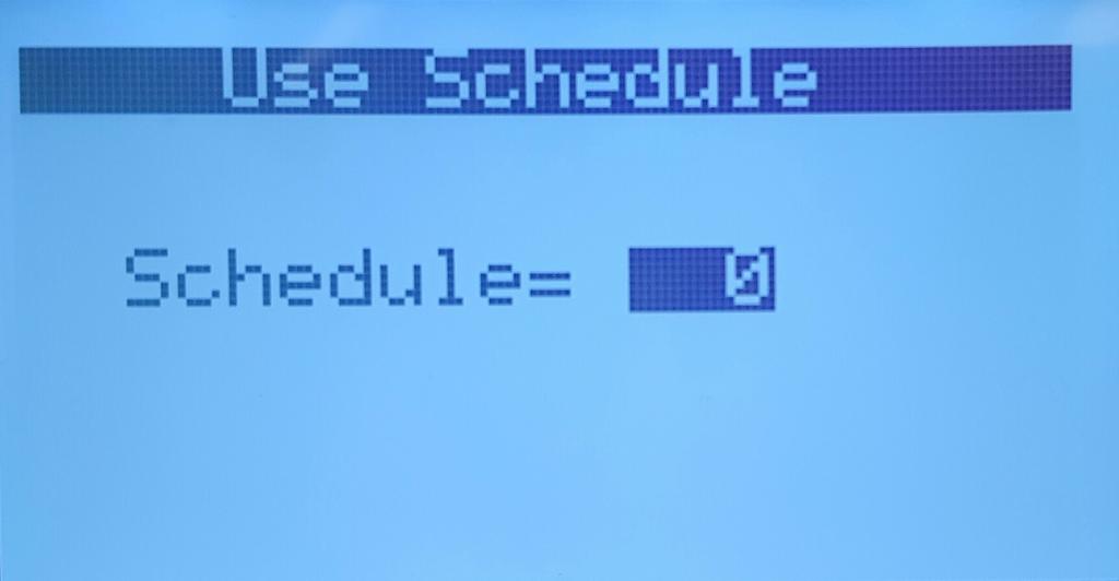
15 Parameter List Main Menu Sub Menu Parameter Input Range Description 1. Use Schedule 2. Edit Schedule Schedule [0-63] Advance Intensify Block Delay Schedule Number [0-63] Squeeze Delay Squeeze >Valve Weld 1 >Mode None Phase Shift Const Current >Heat [0-99] % or >Current >I1 Monitor >PW1 Monitor Cool 1 [ ] ka On On This option only appears when air-over-oil configuration is selected. This option only appears when air-over-oil configuration is selected. This option only appears when air-over-oil configuration is selected. In order to accept changes made to any field, the button must pressed. It is important to make sure that the correct schedule number is selected AND accepted BEFORE completing all of the corresponding settings to follow. Additional time delay to be added to 'Squeeze'. This is usually utilized when 'Cycle Mode' is set to repeat. The squeeze delay will only be applied to the first weld of the repeating cycle. Time delay between the signal to the programmed valve(s) and weld initiation. Default = None Selection of valve(s) to be activated Also referred to as "pre-heat" Default = Phase Shift Phase shift %; does not apply when Mode is set to Const Current Weld current setting does not apply when Mode is set to Phase Shift Default = Must be enabled in order to track/report current errors Default = Must be enabled in order to track/report phase shift abnormalities. Time delay between Weld 1 and Weld 2. Designed to give an impulse effect Rev 1.0
16 Parameter List Main Menu (continued) Sub Menu Parameter Input Range Description 2. Edit Schedule (continued) Slope The number of additional cycles between 'Weld 1' and 'Weld 2' in order to transition between the two gradually. A larger 'Weld 1' will result in a downslope; whereas a larger 'Weld 2' will result in an upslope. Weld 2 >Mode Phase Shift Const Current Default = Phase Shift >Heat [0-99] % Phase shift %; does not apply when '>Mode' is set to Const Current or >Current [ ] ka Weld current setting does not apply when Mode is set to Phase Shift >I2 Monitor >PW2 Monitor Cool 2 Hold Impulses I offset >Change all Block Delay On On [1-99] cycles -1 % 0 % +1 % No Yes Default = Must be enabled in order to track/report current errors Default = Must be enabled in order to track/report phase shift abnormalities. Primarily used when applying multiple impulses; time delay following each 'Weld 2' impulse. Time delay during which the electrodes remain in contact with the part being welded to allow weld nugget to congeal. Time delay following 'Hold' cycle in which the valve(s) release; the next schedule/sequence will not begin until the '' cycle is complete. Default = 1 Number of times to deliver Weld 2, Cool 2. (Impulses do NOT apply to Weld 1, Cool 1) Adjustable increase or decrease to total current delivered by a sequence. This is one of the few adjustable parameters when control is locked. Parameter is only visible when 'Max I offset' is not "0". Default = No No 'I offset' will be applied to the current schedule Yes 'I offset' will be applied to all schedules' This option only appears when air-over-oil configuration is selected Rev 1.0
17 Parameter List Main Menu (continued) Sub Menu Parameter Input Range Description 2. Edit Schedule (continued) Cycle Mode Non-Repeat Repeat Chained Successive Wait Here Default = Non-Repeat Non-repeat Control can be initiated for only one sequence/ schedule even if initiation remains closed. Repeat Sequences/ schedules will continue if initiation remains closed. Chained Schedules are chained together so that consecutive schedules can be sequenced from one initiation. Successive Schedules are chained together so that consecutive schedules will be sequenced from separate initiations. Wait-Here only applies when 'Weld2' is set to 99 cycles. This allows infinite Weld 2 duration until Escape is trig- 3. Copy Schedule Copy From [0-63] Schedule # to be copied Copy To [0-63] Schedule # to be replaced Confirm Yes No Must select "Yes" and press the key to complete the above copy/replace. "DONE!!!" will appear in the title bar once complete. 4. Reset Error Confirm Yes No Must select "Yes" and press the key to complete the above copy/replace. "DONE!!!" will appear in the title bar once complete. 5. Edit Counter Counter Enable Disable Max part Count [0-60,000] Weld per part [1-9,999] RST Counter None PCTR WCTR Both Default = Disable Enable 'Weld count done' will increment with each weld delivered. Error "ER25" will be reported when 'Max part count' = 'Part count done' Default = 60,000 Number at which the 'part count done' reports error "ER25" Default = 1 The number of welds to increment 'part count done' by one. Default = None Resets counter PCTR part counter WCTR weld counter Rev 1.0
18 Parameter List Setup Menu Sub Menu Parameter Input Range Description 1. Config Weld Mode Retraction On Error Sch Select I-Feedback Air-over-oil Retract Open Retract Close Spot Seam1 Seam2 Maintained Momentary Continue Head Lock Stop Internal External Primary Secondary Mode 1 Mode 2 Default = Spot Spot Standard squeeze, weld, hold and off sequence. Seam1 When FS1 or FS2 input is toggled, control will run 'schedule' from 'Squeeze Delay' through 'Cool 2'. If FS1 or FS2 input is held, control will repeat 'Weld 2' and 'Cool 2'. Seam2 FS1 initiation implements same function as in Seam1. FS2, schedule 20, schedule 40 and schedule 60 will always initiate "Spot" Weld Mode Default = Maintained Retraction output directly reflects retraction input Momentary Retraction output changes state with an impulse of retraction input. This parameter is ignored if 'Beat_Mode' is enabled. Default = Continue Continue Further welds are permitted regardless of previous weld status Head Lock On error, valve signal(s) are held on. Additional welds are not permitted until Error Reset occurs. Stop On error, valve signal(s) turn off as normal. Additional welds are not permitted until Error Reset occurs. Default = Internal Internal FS1 will initiate the programmed weld schedule number External FS1 will initiate the weld schedule number according to the binary value represented by PI3, PI4, PI5, and PI6. (FS2 will always initiate weld schedule 20.) Default = Secondary This setting should correspond to the physical location of the sensing coil. Default = Mode 1: air-over-oil setting without retraction Mode 2: air-over-oil setting with retraction enabled using 'Retract Open' and 'Retract Close' settings Time delay to allow for retraction from "pre-weld" position to "fully open" position Sub Menu only appears when 'air-over-oil' is set to "Mode 2" Time delay to allow for closure from "fully open" position to "pre-weld" position Sub Menu only appears when 'air-over-oil' is set to "Mode 2" Rev 1.0
19 Parameter List Setup Menu (continued) Sub Menu Parameter Input Range Description 1. Config (continued) Beat mode AVC AVC nom. Voltage monitor >High >Low Squeeze Sqz. + Weld Wait-Here Disabled Max [1-10] % [ ] volts On [ ] volts [ ] volts Max I offset [0-15] % Water Saver 87 delay Half Cycle [0-199] sec On + - AC Default = Sequence/Schedule will complete with a momentary activation of FS1 or FS2 Squeeze Sequence/Schedule requires continuous activation of FS1 or FS2 until the squeeze sequence is complete, otherwise the sequence will terminate. Sqz. + Weld Welding sequence requires continuous activation of FS1 or FS2 until the weld sequence is complete, otherwise the sequence will terminate. Wait-Here Welding sequence requires continuous activation of FS1 or FS2 until the weld sequence is complete, otherwise the sequence will temporarily pause (retraction will not occur). This setting requires the active schedule's 'Cycle Mode' to also be set to "Wait-Here". Default = Disabled Automatic Voltage Compensation Will add additional percentage to phase shift in order to compensate for diminished supply voltage. (only works with schedules using "Phase Shift" Mode to regulate current) Default = 480 Supply voltage on which the control is designed to operate. Parameter is only visible when 'AVC' is enabled. Default = On High and Low Voltage errors are enabled using the following parameters. Default = 690 Error "ER23" will be triggered if supply voltage is above the set value Parameter is only visible when 'Voltage Monitor' is "On" Default = 160 Error "ER24" will be triggered if supply voltage is below the set value Parameter is only visible when 'Voltage Monitor' is "On" Determines the input range for 'I offset' parameter. For example, if 'Max I offset' is 6%, 'I offset' input range is -6% to +6% Time duration that the water flow signal will remain on following a weld. Default = On The first half cycle is delayed 87degrees (51.6% max) phase shift in order to minimize saturation of the weld transformer Default = + Only the positive half cycle is output - Only the positive half cycle is output AC Alternating positive/negative half cycles are output Rev 1.0
20 Parameter List Setup Menu (continued) Sub Menu Parameter Input Range Description 1. Config (continued) 2. Calibration Power factor [0-99] % Blanking Display return Clear 3. I/O Map (see page 21) 4. Error Map (see page 22) 5. Stepper [0-10] min None I/O Map Calibration Config Stepper Counter Schedule All Toroid [ ] mv/ka Max I [20-60] ka Default = 20 AC line scale [ ] Default = 75 0 "Automatic Power Factor" mode 1-99 Manual power factor delay. Value must be determined by the Power Factor Delay and will vary for each machine. If a primary or secondary coil is NOT installed, a manual power factor of 80% is recommended. Automatic Power Factor may react abnormally if enabled without a coil. The number of weld cycles to exclude from measurement and limit testing 0 Disabled Length of time before the display returns to 'Status Page 1' Clearing data from this menu does not require a confirmation. "DONE!!!" will appear in the title bar as verification. Default = 150 For accurate current monitoring Default = 1.0 For accurate voltage monitoring Stepper Disable Heat Tip dress [0-9,999] RST stepper No Yes Default = Disable Heat Stepper function enabled with current compensation Default = 9,000 When Count Done = Tip dress, error (ER31) will trigger Selecting "Yes" and pressing the Count done to zero key will reset the Rev 1.0
21 Parameter List Setup Menu (continued) Sub Menu Parameter Input Range Description 5. Stepper (continued) [01-10]:Count [0-9,999] >Heat+ [0-99] % >Current+ [ ] ka The number of welds required to move onto the next step Additional phase shift to be added to Weld 1 and Weld 2 Heat settings Only applies when the weld Mode is set to Phase Shift. Additional current to be added to Weld 1 and Weld 2 Current settings Only applies when the weld Mode is set to Const Current. 6. Utility Backup Data (see page 10) Restore Data (see page 11) Rev 1.0
22 I/O Map Setup Menu (continued) Input/Output Options Description PI1 PI2 PI3 PI4 PI5 PI6 TT1 2nd stage Back step PCTR Edit lock PS1 Interlock WCTR Reset Error reset Sch. Select 1 Stepper reset 2nd Stage Interlock Sch. Select 2 Error Reset (Not Used) Back step Sch. Select 4 Retraction (Not Used) Stepper Reset Sch. Select 8 Edit lock Escape TT1 Temperature Limit Switch (also called TLS) 2nd stage For valve closure before squeeze; to ensure good electrode position Back step Return to previous schedule in Successive Cycle mode PCTR Part counter reset Edit lock closed = control locked; open = control unlocked PS1 Pressure switch signal Interlock Signal to authorize weld; used with PO4 Interlock WCTR Weld counter reset Error reset Clear error in order resume function Sch. Select 1 Binary value of one for externally selecting schedule Stepper reset Return stepper to Zero position 2nd stage For valve closure before squeeze; to ensure good electrode position Interlock Signal to authorize weld; used with PO4 Interlock Sch. Select 2 Binary value of two for externally selecting schedule Error reset clears error in order resume function Back step Return to previous schedule in Successive Cycle mode Sch. Select 4 Binary value of four for externally selecting schedule Retraction Retract input command for release of valves Stepper reset Return stepper to Zero position Sch. Select 8 Binary value of eight for externally selecting schedule Edit lock closed = control locked; open = control unlocked Escape command to escape current weld schedule/sequence PO1 PO2 PO3 PO4 Any Error Retraction Force Error Major Error AVC Error Contactor Error Step End EOS Current Error Any Error Count end Water Saver Step End Current Error AVC Error Interlock Any Error Major or minor error is detected Retract Output Command to retract (in addition to programmed valves) Force Error Pressure switch is not detecting proper electrode force Major Error Major error detected; determined by Error Map settings AVC Error Automated Voltage Compensation is insufficient Contactor Error Energy is being shunted; (typically set to trip a breaker) Step End Programmable step has completed its count EOS 0.5sec signal at the end of each weld sequence Current Error Constant Current Control in insufficiently compensating Any Error Major or minor error is detected Count end Max part count has been reached Water Saver signal turns off after a set time following the last weld Step End Programmable step has completed its count Current Error Constant Current Control in insufficiently compensating AVC Error Automated Voltage Compensation is insufficient Interlock Request to weld signal from external source; used with PI Rev 1.0
23 Error List # Name # Name 1 Config error 33 RST 2 Calibration error 34 SYNC error 3 Schedule error 35 PNW error 4 Use Schedule error 36 DC Safety relay err AC Safety relay err. 6 Counter error 38 7 Stepper error 39 8 I/O Map error 40 9 E-stop error TC1 error P1-No weld 43 Pre-high current1 12 PS1 error 44 Pre-low current1 13 SCR short 45 Pre-high current2 14 2nd stage error 46 Pre-low current2 15 TT1 error Interlock error High current Low current High current Low current High voltage Low voltage Counter end 57 Retract open error 26 Stepper end High PW1 59 Retract input closed 28 Low PW1 60 PS not ready 29 High PW2 61 Retract not ready 30 Low PW2 62 2nd stage not ready 31 Tip dress pre-warn AVC error 64 Interlock not ready Note: All error defaults are set to Minor errors. Error handling should be set under the configurations menu and by utilizing the Any Error, Contactor Error, and Major Error options available for the programmable outputs in the I/O Map Rev 1.0
24 Warranty and Service Policy ENTRON takes great pride in offering its customers a quality product that is built to withstand numerous industrial conditions. The products are built to last, and in return for customer loyalty, we offer a limited warranty on all new control panels. ENTRON Controls, LLC., warrants that all ENTRON control panels except Mid-frequency Inverter controls, silicon controlled rectifiers (SCRs), insulated gate bipolar transistors (IGBTs), SCR and IGBT assemblies, circuit breakers, and electro-mechanical contactors, are free of manufacturing defects for a period of TWO YEARS from the date of original purchase and, in the event of a manufacturing defect, ENTRON will repair or replace, at its discretion, the defective part without any cost for parts or labor. All SCRs, IGBTs, SCR and IGBT assemblies, circuit breakers, and electro-mechanical contactors in ENTRON control panels are covered by a limited warranty from the original manufacturer. If these parts fail because of a manufacturing defect, they will not be repaired or replaced by ENTRON, but will be returned by ENTRON to the original manufacturer in accordance with said manufacturer s warranty. ENTRON Controls, LLC., warrants that all Mid-frequency Inverter controls are free of manufacturing defects for a period of ONE YEAR from the date of original purchase and, in the event of a manufacturing defect, ENTRON will repair or replace, at its discretion, the defective part without any cost for parts or labor. To obtain repairs or replacement parts under this warranty, the defective part must be returned, prepaid, to ENTRON Controls, LLC., 1402 S. Batesville Road, Greer, South Carolina Please send your repair to the attention of Service with a description of the problem you are experiencing, contact person and phone number. EXCLUSIONS: This warranty does not cover damage by accident or misuse, unauthorized repair or modification to any control assembly by the customer. The warranty period is considered from date of shipment and is tracked by ENTRON s serial numbering system. USE OF OUT OF WARRANTY REPAIR SERVICE: To obtain service for any printed circuit board assembly or welding control after the warranty period, send the assembly or control, prepaid, to ENTRON Controls, LLC., and ENTRON will repair the printed circuit board assembly or control and return it to you without further warranty. Additional service charges will be invoiced at time of shipment. Thank you for using ENTRON Controls. Your ENTRON Controls, LLC., Original Equipment Manufacturers (OEMs), Dealers and Distributors are your first response contact to secure technical assistance on control or welding problems. Should they be unable to assist you, please contact your ENTRON sales representative or the factory directly. Contact the factory at Rev 1.0
Entron Controls, LLC S. Batesville Road Greer, SC Phone: fax:
 Entron Controls, LLC. 1402 S. Batesville Road Greer, SC 29650 Phone: 864.416.0190 fax: 864.416.0195 www.entroncontrols.com 1 700230 1 Rev 3.0 Table of Contents 1.0 Introduction 1.1 Features... 3 1.2 Reference
INSTRUCTION MANUAL. J800 Weld Controller. 3/25/2018 Revision
 INSTRUCTION MANUAL J800 Weld Controller 3/25/2018 Revision 1.1.1.1 THIS PAGE IS INTENTIONALLY LEFT BLANK ii INSTALLATION AND OPERATION Janda Company, Inc. J800 WELDING CONTROLLER TO END USERS: This Weld
Controls, LLC. MICROPROCESSOR BASED RESISTANCE WELDING CONTROLS. PRODUCT CATALOG and SPECIFICATIONS
 Controls, LLC. MICROPROCESSOR BASED RESISTANCE WELDING CONTROLS PRODUCT CATALOG and SPECIFICATIONS Effective: 01/08 Supersedes: 09/07 ENTRON Controls, LLC. 601 High Tech Court Greer, SC 29650 (864) 416-0190
WELDING CONTROL UNIT: TE 450 USER MANUAL
 j WELDING CONTROL UNIT: TE 450 USER MANUAL RELEASE SOFTWARE No. 1.50 DOCUMENT NUMBER: MAN 4097 EDITION: MARCH 1998 This page is left blank intentionally. 2 / 34 TABLE OF CONTENTS SUBJECTS PAGE WELDING
Sentinel I24 Digital Input and Output Configuration
 Application Bulletin: #155 Date: October 19, 2007 Sentinel I24 Digital Input and Output Configuration The Sentinel I24 can communicate with external hardware using digital inputs and outputs. There are
User Manual CC DC 24 V 5A. Universal Control Unit UC-1-E. General Information SET. Universal Control Unit UC-1 Of Central Lubrication PAUSE CONTACT
 Universal Control Unit UC-1-E User Manual General Information Universal Control Unit UC-1 Of Central Lubrication CC DC 24 V 5A / M 15 SL /MK 31 M Z 30 General Information Contents Universal Control Unit
VLC-3 USER'S MANUAL. Light Program Controller. M rev. 04 K rev. 00 & ( ( 5, 352*5$0 1 : $ 2 ' 6(77,1*6 )81&7,216
81&7,216") Light Program Controller VLC-3 USER'S MANUAL +50,1 +50,1 1 : $ ' 2 7. 6 8 ' 5, 7 6 6. $ ( 3 352*5$0 0,16(& )81&7,216 6(77,1*6 & 8 5 5 ( 1 7 3 ( 5, 2 ' M 890-00189 rev. 04 K 895-00406 rev. 00 GENERAL...
Light Program Controller VLC-3 USER'S MANUAL +50,1 +50,1 1 : $ ' 2 7. 6 8 ' 5, 7 6 6. $ ( 3 352*5$0 0,16(& )81&7,216 6(77,1*6 & 8 5 5 ( 1 7 3 ( 5, 2 ' M 890-00189 rev. 04 K 895-00406 rev. 00 GENERAL...
User Guide. Centrex Recording Interface
 User Guide Centrex Recording Interface Table of Contents Introduction... 2 The Meridian Business Set... 3 Key Numbering Plan (18 button add-on)... 4 Key Numbering Plan (36 button add-on)... 5 Key Numbering
RD RACK MOUNT DIMMER OWNERS MANUAL VERSION /09/2011
 RD - 122 RACK MOUNT DIMMER OWNERS MANUAL VERSION 1.3 03/09/2011 Page 2 of 14 TABLE OF CONTENTS UNIT DESCRIPTION AND FUNCTIONS 3 POWER REQUIREMENTS 3 INSTALLATION 3 PLACEMENT 3 POWER CONNECTIONS 3 OUTPUT
M150SP USER S AND INSTALLER S MANUAL. v2.0 REV. 03/2017
 M150SP USER S AND INSTALLER S MANUAL v2.0 REV. 03/2017 00. CONTT 01. SAFETY INSTRUCTIONS INDEX 01. SAFETY INSTRUCTIONS STANDARDS TO FOLLOW 02. THE DEVICE TECHNICAL SPECIFICATIONS VISUAL ASPECT CONNECTORS
Noise Detector ND-1 Operating Manual
 Noise Detector ND-1 Operating Manual SPECTRADYNAMICS, INC 1849 Cherry St. Unit 2 Louisville, CO 80027 Phone: (303) 665-1852 Fax: (303) 604-6088 Table of Contents ND-1 Description...... 3 Safety and Preparation
Master Time Clock MTC Users Manual
 Master Time Clock MTC-6000 Users Manual Midwest Time Control Phone (972)987-4408 Toll Free (888)713-0373 FAX (877)720-9291 www.midwest-time.com sales@midwest-time.com TABLE OF CONTENTS TOPIC PAGE GENERAL
Transfer Switch. OTECA (Spec A) OTECB (Spec A) OTECC (Spec A) OTECD (Spec A) Amperes. English Original Instructions (Issue 5)
 OTECB (Spec A) OTECC (Spec A) OTECD (Spec A) Amperes. English Original Instructions (Issue 5)") Operator Manual Transfer Switch 40-1000 Amperes OTECA (Spec A) OTECB (Spec A) OTECC (Spec A) OTECD (Spec A) English Original Instructions 10-2015 962-0131 (Issue 5) Table of Contents 1. SAFETY PRECAUTIONS...
Operator Manual Transfer Switch 40-1000 Amperes OTECA (Spec A) OTECB (Spec A) OTECC (Spec A) OTECD (Spec A) English Original Instructions 10-2015 962-0131 (Issue 5) Table of Contents 1. SAFETY PRECAUTIONS...
FN:4181M5.DOC MC4181N SERIES MASTER CLOCKS MC4181N
 FN:4181M5.DOC MC4181N SERIES MASTER CLOCKS MC4181N TABLE OF CONTENTS 1.0 INTRODUCTION 2.0 SPECIFICATIONS 3.0 INSTALLATION 4.0 GETTING STARTED 4.1 The Auto-Prompt Display 4.2 The Cursor, Entering Data 4.3
AES-402 Automatic Digital Audio Switcher/DA/Digital to Analog Converter
 Broadcast Devices, Inc. AES-402 Automatic Digital Audio Switcher/DA/Digital to Analog Converter Technical Reference Manual Broadcast Devices, Inc. Tel. (914) 737-5032 Fax. (914) 736-6916 World Wide Web:
SCALE & WEIGHT DISPLAYS
 The MICRO SERIES SCALE & WEIGHT DISPLAYS LARGE DIGIT MODELS Mighty-5S DPM MODELS Micro-S & Mighty-1S Mighty-1S Micro-S ELECTRO-NUMERICS, INC. Introduction The Electro-Numerics family of Digital Panel Meters
MP-7424 Football Scoreboard with MP5000 Console
 MP-7424 Football Scoreboard with MP5000 Console With additional instructions for Track and Soccer Operator s Manual Volume VII Rev. 10/17/07 Table of Contents Table of Contents...2 1.0 Keypad Console...3
EAN-Performance and Latency
 EAN-Performance and Latency PN: EAN-Performance-and-Latency 6/4/2018 SightLine Applications, Inc. Contact: Web: sightlineapplications.com Sales: sales@sightlineapplications.com Support: support@sightlineapplications.com
FN:4181NX_M1.DOC MC4181NX MASTER CLOCK MC4181NX
 FN:4181NX_M1.DOC MC4181NX MASTER CLOCK MC4181NX TABLE OF CONTENTS 1.0 INTRODUCTION 2.0 SPECIFICATIONS 3.0 INSTALLATION 4.0 GETTING STARTED 4.1 The Auto-Prompt Display 4.2 The Cursor, Entering Data 4.3
USER MANUAL FOR THE ANALOGIC GAUGE FIRMWARE VERSION 1.1
 by USER MANUAL FOR THE ANALOGIC GAUGE FIRMWARE VERSION 1.1 www.aeroforcetech.com Made in the USA! WARNING Vehicle operator should focus primary attention to the road while using the Interceptor. The information
SXT SXGA TFT NEMA 4/12 Flat Panel Monitor. User s Guide
 SXT2010 20.1 SXGA TFT NEMA 4/12 Flat Panel Monitor User s Guide 302010(A) (was document no. 920A0007 version 1.0), revised 12/98 Viewtronix Viewtronix reserves the right to make changes in specifications
This document is a reference document that shows the menus in the 5500sc, 9610sc and 9611sc analyzers. There are 3 top-level menus:
 Controller menus 5500sc, 9610sc and 9611sc analyzers DOC273.53.80566 Introduction This document is a reference document that shows the menus in the 5500sc, 9610sc and 9611sc analyzers. There are 3 top-level
MONITOR POWER Shiloh Road Alpharetta, Georgia (770) FAX (770) Toll Free
 FAX (770) Toll Free") Instruction Manual Model 2099-10xx 10MHz Frequency Source April 2014, Rev. H MENU INTERNAL LEVEL = +10dBm MONITOR POWER 1 2 MODEL 2099 FREQUENCY SOURCE CROSS TECHNOLOGIES INC. ALARM OVEN REMOTE EXECUTE
Instruction Manual Model 2099-10xx 10MHz Frequency Source April 2014, Rev. H MENU INTERNAL LEVEL = +10dBm MONITOR POWER 1 2 MODEL 2099 FREQUENCY SOURCE CROSS TECHNOLOGIES INC. ALARM OVEN REMOTE EXECUTE
STD-525T PRECISION TIMER
 FN:STD525TM1.DOC STD-525T PRECISION TIMER DESCRIPTION The STD-525T Precision Timer measures and displays accurate elapsed time in minutes, seconds, tenths of seconds, and hundredths of seconds (MM.SS.TH)
AC WELDER STA SERIES OPERATION MANUAL
 AC WELDER STA SERIES OPERATION MANUAL 990-351 Rev H Copyright 2001, 2002, 2014 Amada Miyachi America The engineering designs, drawings and data contained herein are the proprietary work of AMADA MIYACHI
Operating Instructions
 CNTX Contrast sensor Operating Instructions CAUTIONS AND WARNINGS SET-UP DISTANCE ADJUSTMENT: As a general rule, the sensor should be fixed at a 15 to 20 angle from directly perpendicular to the target
VARIABLE SPEED USER MANUAL. Premium Efficiency Variable Speed Motor
 165 VARIABLE SPEED USER MANUAL Premium Efficiency Variable Speed Motor COPYRIGHT Copyright 2013, Regal Beloit America, Inc. Tipp City, Ohio. All rights reserved. TRADEMARKS All trademarks and registered
AES-404 Digital Audio Switcher/DA/Digital to Analog Converter
 Broadcast Devices, Inc. AES-404 Digital Audio Switcher/DA/Digital to Analog Converter Technical Reference Manual Broadcast Devices, Inc. Tel. (914) 737-5032 Fax. (914) 736-6916 World Wide Web: www.broadcast-devices.com
Troubleshooting CS800/LC900 Bikes
 Troubleshooting CS800/LC900 Bikes CS800/900LC Bike Troubleshooting Entering the Maintenance Mode 15 Touch Screen: The Maintenance Mode is designed to help the tech determine certain faults in the upper
12months. on-site warranty. DZE ELECTRONIC PRESSURE SWITCH for detection of overload per EN 81 2 featuring two adjustable switching points
 BUCHER PRODUCTS AVAILABLE FROM HYDRATEC DZE ELECTRONIC PRESSURE SWITCH for detection of overload per EN 81 2 featuring two adjustable switching points 12months on-site warranty All our work comes with
USER MANUAL FOR THE ANALOGIC GAUGE FIRMWARE VERSION 1.0
 by USER MANUAL FOR THE ANALOGIC GAUGE FIRMWARE VERSION 1.0 www.aeroforcetech.com Made in the USA! WARNING Vehicle operator should focus primary attention to the road while using the Interceptor. The information
16-BIT LOAD CELL/DUAL STATUS INPUT
 16-BIT LOAD CELL/DUAL STATUS INPUT On-board Excitation. +5VDC, (120mA). State-of-the-art Electromagnetic Noise Suppression Circuitry. Ensures signal integrity even in harsh EMC environments. Optional Excitation
USER S GUIDE. 1 Description PROGRAMMABLE 3-RELAY LOGIC MODULE
 1 Description The is a programmable 3 relay logic module that may be used for multiple applications, including simple timing, door mounted sensor inhibiting and advanced relay sequencing. The contains
UNIVERSAL DIGITAL METER DC Volts and Amps AC RMS Volts and Amps Thermocouples and RTDs Process Signals Strain Gauge and Load Cell
 99 Washington Street Melrose, MA 02176 Fax 781-665-0780 TestEquipmentDepot.com UNIVERSAL DIGITAL METER DC Volts and Amps AC RMS Volts and Amps Thermocouples and RTDs Process Signals Strain Gauge and Load
Exercise 4-2. Counting of Actuator Cycles EXERCISE OBJECTIVE & & &
 Exercise 4-2 EXERCISE OBJECTIVE To describe the operation of an electrical counter; To assemble and test a continuous reciprocation system; To extend and retract a cylinder a definite number of times using
User Guide UD51. Second encoder small option module for Unidrive. Part Number: Issue Number: 5.
 EF User Guide UD51 Second encoder small option module for Unidrive Part Number: 0460-0084-05 Issue Number: 5 www.controltechniques.com Safety Information The option card and its associated drive are intended
FRQM-2 Frequency Counter & RF Multimeter
 FRQM-2 Frequency Counter & RF Multimeter Usage Instructions Firmware v2.09 Copyright 2007-2011 by ASPiSYS Ltd. Distributed by: ASPiSYS Ltd. P.O.Box 14386, Athens 11510 (http://www.aspisys.com) Tel. (+30)
Provides an activation of Relay 1 triggered by Input 1. The function also provides an option for reverse-logic on the activation of Input 1.
 USER S GUIDE PROGRAMMABLE 3-RELAY LOGIC MODULE 1 Description The is a programmable 3 relay logic module that may be used for multiple applications, including simple timing, door mounted sensor inhibiting
SPECIFICATION NO Model 207 Automatic GTAW Welding System
 1.0 Introduction The Model 207 is a completely self-contained Gas Tungsten Arc Welding (GTAW) System requiring only input power, inert gas and AMI Welding Head (or manual torch) for operation. Its small
Triple RTD. On-board Digital Signal Processor. Linearization RTDs 20 Hz averaged outputs 16-bit precision comparator function.
 Triple RTD SMART INPUT MODULE State-of-the-art Electromagnetic Noise Suppression Circuitry. Ensures signal integrity even in harsh EMC environments. On-board Digital Signal Processor. Linearization RTDs
LAUREL ELECTRONICS, INC.
 LAUREL ELECTRONICS, INC. Laureate Digital Panel Meter for Process, Strain & Potentiometer Follower Signals Features Selectable ±0.2, ±2, ±20, ±200, ±300 & ±600 Vdc voltage ranges Selectable ±2, ±20, ±200
Tech Support: Customer Service: General Tech Questions: Tech Docs:
 Tech Support: 1-800-407-4545 Customer Service: 1-800-523-2462 General Tech Questions: Tech_Services@beainc.com Tech Docs: www.beasensors.com BR3-X Programmable 3 Relay Advanced Logic Module & Restroom
Electronic M.O.P Card. Instruction Manual Model D
 Electronic M.O.P Card Instruction Manual Model D10341-000 Table of Contents 1. General Description................................................................ 1 2. Specifications.....................................................................
MS2540 Current Loop Receiver with RS485 Communication
 MS2540 Current Loop Receiver with RS485 Communication User Manual Metal Samples Company A Division of Alabama Specialty Products, Inc. 152 Metal Samples Rd., Munford, AL 36268 Phone: (256) 358 4202 Fax:
Sprite TL Quick Start Guide
 Sprite TL Quick Start Guide with 115 VAC Power Cord and 4-Conductor Signal Cable Reference Manual Sprite TL Online and downloadable Product Manuals and Quick Start Guides are available at www.hydrosystemsco.com
Ford AMS Test Bench Operating Instructions
 AMS Test Bench 09/2013 Ford AMS Test Bench Operating Instructions The Ford Meter Box Co., Inc. 775 Manchester Avenue, P.O. Box 443, Wabash, Indiana, USA 46992-0443 Telephone: 260-563-3171 FAX: 800-826-3487
Modbus for SKF IMx and Analyst
 User manual Modbus for SKF IMx and SKF @ptitude Analyst Part No. 32342700-EN Revision A WARNING! - Read this manual before using this product. Failure to follow the instructions and safety precautions
Single Axis Position Controller
 SERIES P9511 Single Axis Position Controller Compact Construction Simple Go-to operation Integrated Relay Output Integrated Mains Power Supply ELEKTRO-TRADING sp. Z o.o. 44-109 Gliwice, ul. Mechaników
OPERATION AND MAINTENANCE
 BAS MS/TP Enabled OPERATION AND MAINTENANCE An Company Contents Powering Up For The First Time... 3 Setting MSTP Communication Parameters... 4 Changing the MSTP Address... 4 Changing the BACNET ID... 5
OWNERS MANUAL. Revision /01/ Lightronics Inc. 509 Central Drive Virginia Beach, VA Tel
 OWNERS MANUAL Revision 1.8 09/01/2002 OWNERS MANUAL Page 2 of 12 AR-1202 UNIT DESCRIPTION The AR-1202 consists of a processor and 12 dimmer channels of 2.4KW each. Each dimmer channel is protected by a
Junior Max (JR Max ) Controller
 Controller") Get more done TM Junior Max (JR Max ) Controller stations Operating Instructions Thank you for purchasing this advanced, highly featured Irritrol Junior MAX controller. The Junior MAX is the latest addition
Get more done TM Junior Max (JR Max ) Controller stations Operating Instructions Thank you for purchasing this advanced, highly featured Irritrol Junior MAX controller. The Junior MAX is the latest addition
ORM0022 EHPC210 Universal Controller Operation Manual Revision 1. EHPC210 Universal Controller. Operation Manual
 ORM0022 EHPC210 Universal Controller Operation Manual Revision 1 EHPC210 Universal Controller Operation Manual Associated Documentation... 4 Electrical Interface... 4 Power Supply... 4 Solenoid Outputs...
Ford AMS Test Bench Operating Instructions
 THE FORD METER BOX COMPANY, INC. ISO 9001:2008 10002505 AMS Test Bench 09/2013 Ford AMS Test Bench Operating Instructions The Ford Meter Box Co., Inc. 775 Manchester Avenue, P.O. Box 443, Wabash, Indiana,
KNX Dimmer RGBW - User Manual
 KNX Dimmer RGBW - User Manual Item No.: LC-013-004 1. Product Description With the KNX Dimmer RGBW it is possible to control of RGBW, WW-CW LED or 4 independent channels with integrated KNX BCU. Simple
User Manual rev: Made in Taiwan
 CV-500S HDMI to Component/CVBS & Audio Scaler Converter User Manual rev: 131218 Made in Taiwan The CV-500S HDMI to Component/CVBS & Audio Scaler Converter has been tested for conformance to safety regulations
Safety Information. Camera System. If you back up while looking only at the monitor, you may cause damage or injury. Always back up slowly.
 Table of Contents Introduction...3 Safety Information...4-6 Before Beginning Installation...7 Installation Guide...8 Wiring Camera & Monitor...9-10 Replacement Installation Diagram...11 Clip-On Installation
2 CHANNEL RECEIVER DISPLAY POTENTIOMETER COM2 NC2 NO2
 2 CHANNEL RECEIVER RECTSHIVE915-DX Please read this manual carefully before installing the product. 1 DESCRIPTION Receiver Rolling Code, 2 channels with dry contact relay output 20A a 12 Vdc. Programming
MG-XV operating instruction. Measuring of norm signals, 4-8-digit. Panel instrument type MG-BV Construction instrument type MG-AV
 MG-XV operating instruction Measuring of norm signals, 4-8-digit Panel instrument type MG-BV Construction instrument type MG-AV Contents 1. Brief description... 3 2. Safety instructions... 3 2.1. Proper
USER MANUAL. 22" Class Slim HD Widescreen Monitor L215DS
 USER MANUAL 22" Class Slim HD Widescreen Monitor L215DS TABLE OF CONTENTS 1 Getting Started Package Includes Installation 2 Control Panel / Back Panel Control Panel Back Panel 3 On Screen Display 4 Technical
BooBox Flex. OPERATING MANUAL V1.1 (Feb 24, 2010) 6 Oakside Court Barrie, Ontario L4N 5V5 Tel: Fax:
 6 Oakside Court Barrie, Ontario L4N 5V5 Tel: Fax:") BooBox Flex OPERATING MANUAL V1.1 (Feb 24, 2010) 6 Oakside Court Barrie, Ontario L4N 5V5 Tel: 905-803-9274 Fax: 647-439-1470 www.frightideas.com Connections The BooBox Flex is available with Terminal Blocks
BooBox Flex OPERATING MANUAL V1.1 (Feb 24, 2010) 6 Oakside Court Barrie, Ontario L4N 5V5 Tel: 905-803-9274 Fax: 647-439-1470 www.frightideas.com Connections The BooBox Flex is available with Terminal Blocks
OWNERS MANUAL. Revision /29/ Lightronics Inc. 509 Central Drive Virginia Beach, VA Tel
 OWNERS MANUAL Revision 1.87 01/29/2006 Page 2 of 17 TABLE OF CONTENTS AR-1202 UNIT DESCRIPTION 3 EXTERNAL CONTROLS 3 POWER REQUIREMENTS 3 INSTALLATION 3 Physical Location 3 Power Input Connections 3 Three
TRANSCENSION 6-CHANNEL DMX DIMMER PACK (order code: BOTE40) USER MANUAL
 USER MANUAL") www.prolight.co.uk TRANSCENSION 6-CHANNEL PACK (order code: BOTE40) USER MANUAL SAFETY WARNING FOR YOUR OWN SAFETY, PLEASE READ THIS USER MANUAL CAREFULLY BEFORE YOUR INITIAL START-UP! CAUTION! Keep this
www.prolight.co.uk TRANSCENSION 6-CHANNEL PACK (order code: BOTE40) USER MANUAL SAFETY WARNING FOR YOUR OWN SAFETY, PLEASE READ THIS USER MANUAL CAREFULLY BEFORE YOUR INITIAL START-UP! CAUTION! Keep this
MATE3 Owner s Manual Addendum
 Purpose MATE3 Owner s Manual Addendum This document is an addendum to 900-0117-01-00, Revision C of the MATE3 System Display and Controller Owner s Manual. It provides descriptions of changes to the MATE3
ST-4000 SIGNAL LEVEL METER
 ST-4000 SIGNAL LEVEL METER Table of Contents Features / Specifications.... 1 Keypad Illustration....... 2 Keypad Controls.... 2 Getting Started: Powering the Meter.... 3 Quick Use Instructions.. 3 Main
PSM-003. Micro Polarization Controller/Scrambler. User Guide
 PSM-003 Micro Polarization Controller/Scrambler User Guide Version: 1.0 Date: August 23, 2012 General Photonics, Incorporated is located in Chino California. For more information visit the company's website
Comfort System T-32-P Universal Thermostat. Operation Manual
 TM Comfort System T-32-P Universal Thermostat TM O Operation Manual Your new Comfort System T-32-P Universal Thermostat has been built using the highest quality components and design currently available.
DIGITAL TIME CLOCK. used with the Meal-Time Control Panel. AGRI-TIME TM Control Instruction Page 1
 TM AGRI- DIGITAL CLOCK used with the 34385 Meal-Time Control Panel MF1116A12 May 1995 Page 1 Warranty Information Chore-Time Equipment warrants each new product manufactured by it to be free from defects
AES Channel Digital/Analog Audio Switcher/DA/Digital to Analog Converter
 Broadcast Devices, Inc. AES-408 8 Channel Digital/Analog Audio Switcher/DA/Digital to Analog Converter Technical Reference Manual Broadcast Devices, Inc. Tel. (914) 737-5032 Fax. (914) 736-6916 World Wide
MENU EXECUTE Shiloh Road Alpharetta, Georgia (770) FAX (770) Toll Free
 FAX (770) Toll Free") Instruction Manual Model 2584-31 Combiner May 2011, Rev. A RF MONITOR GAIN = -15 MENU MODEL 2584 COMBINER CROSS TECHNOLOGIES INC. ALARM REMOTE POWER EXECUTE Data, drawings, and other material contained
Instruction Manual Model 2584-31 Combiner May 2011, Rev. A RF MONITOR GAIN = -15 MENU MODEL 2584 COMBINER CROSS TECHNOLOGIES INC. ALARM REMOTE POWER EXECUTE Data, drawings, and other material contained
ST-4000D SIGNAL LEVEL METER
 ST-4000D SIGNAL LEVEL METER Rev 100606 Table of Contents Features / Specifications.... 1 Keypad Illustration....... 2 Keypad Controls.... 2 Getting Started: Powering the Meter...... 3 Quick Use Instructions.....
HD Digital Set-Top Box Quick Start Guide
 HD Digital Set-Top Box Quick Start Guide Eagle Communications HD Digital Set-Top Box Important Safety Instructions WARNING TO REDUCE THE RISK OF FIRE OR ELECTRIC SHOCK, DO NOT EXPOSE THIS PRODUCT TO RAIN
STORED ENERGY POWER SUPPLY 125/300/1000ADP OPERATION MANUAL Rev G
 STORED ENERGY POWER SUPPLY 125/300/1000ADP OPERATION MANUAL 990-922 Rev G Copyright 2012-2017 Amada Miyachi America The engineering designs, drawings and data contained herein are the proprietary work
VT VGA TFT NEMA 4/12 Flat Panel Monitor. User s Guide
 VT1040 10.4 VGA TFT NEMA 4/12 Flat Panel Monitor User s Guide 301040(A) (was document no. 920A0001 version 1.1), revised 01/98 Viewtronix Viewtronix reserves the right to make changes in specifications
Standard RS232 RS ma
 1 / 5 CONTROL AND VISUALIZATION OF AC CURRENT IN SINGLE PHASE LINES BY EXTERNAL SHUNT Function Operating mode Current control Frequency control DC component control Shunt Timer Resolution Current precision
LEVEL ADJUST POWER Shiloh Road Alpharetta, Georgia (770) FAX (770) Toll Free
 FAX (770) Toll Free") Instruction Manual Model 1200-07 Amplifier September 2010 Rev A MONITOR J1 LEVEL ADJUST POWER MODEL 1200 AMPLIER CROSS TECHNOLOGIES, INC. Data, drawings, and other material contained herein are proprietary
Instruction Manual Model 1200-07 Amplifier September 2010 Rev A MONITOR J1 LEVEL ADJUST POWER MODEL 1200 AMPLIER CROSS TECHNOLOGIES, INC. Data, drawings, and other material contained herein are proprietary
Vorne Industries. 87/719 Analog Input Module User's Manual Industrial Drive Itasca, IL (630) Telefax (630)
 Telefax (630)") Vorne Industries 87/719 Analog Input Module User's Manual 1445 Industrial Drive Itasca, IL 60143-1849 (630) 875-3600 Telefax (630) 875-3609 . 3 Chapter 1 Introduction... 1.1 Accessing Wiring Connections
Vorne Industries 87/719 Analog Input Module User's Manual 1445 Industrial Drive Itasca, IL 60143-1849 (630) 875-3600 Telefax (630) 875-3609 . 3 Chapter 1 Introduction... 1.1 Accessing Wiring Connections
Installation and User Guide 458/CTR8 8-Channel Ballast Controller Module
 Installation and User Guide 458/CTR8 8-Channel Ballast Controller Module Helvar Data is subject to change without notice. www.helvar.com i Contents Section Page Introduction 1 Installation 2 1. Attach
PLC Control Unit for a CSM-E Electrical Compact Clean Steam Generator
 3.635.5275.254 IM-P486-18 CH Issue 3 PLC Control Unit for a CSM-E Electrical Compact Clean Steam Generator Installation, Start-up and Operation Manual 1. Safety information 2. General product information
SC26 Magnetic Field Cancelling System
 SPICER CONSULTING SYSTEM SC26 SC26 Magnetic Field Cancelling System Makes the ambient magnetic field OK for electron beam tools in 300 mm wafer fabs Real time, wideband cancelling from DC to > 9 khz fields
Installation and Tuning Manual DAC 7000 DAC 2X
 Installation and Tuning Manual DAC 7000 DAC 2X DISCLAIMER While every effort has been made to ensure the accuracy of this document, Wayne s, Inc. nor its dealers assumes any responsibility for omissions
Product Identification
 Operation Manual Multi-display 10-Channel and 16-Channel Timers Product Identification The Prince Castle Model 755 Series Multi-display 10-Channel Timer and 16-Channel Timer are easy-to-use timers that
SPECIFICATION NO NOTE
 NOTE The Model 207-1 is a special version of the standard M-207 Power Supply. It has been altered for a special applications requiring low current operation at high arc voltages in ambient and pressurized
SceneStyle2 User Guide
 SceneStyle2 User Guide Mode Lighting (UK) Limited. The Maltings, 63 High Street, Ware, Hertfordshire, SG12 9AD, UNITED KINGDOM. Telephone: +44 (0) 1920 462121 Facsimile: +44 (0) 1920 466881 e-mail: website:
PRO-ScalerHD2V HDMI to VGA & Audio Scaler Converter. User s Guide. Made in Taiwan
 PRO-ScalerHD2V HDMI to VGA & Audio Scaler Converter User s Guide Made in Taiwan Congratulations for owning a gofanco product. Our products aim to meet all your connectivity needs wherever you go. Have
Utility Amplifier GA6A Model
 Utility Amplifier GA6A Model Installation and Use Manual 2004 Bogen Communications, Inc. All rights reserved. Specifications subject to change without notice. 54-5757-03D 1503 NOTICE: Every effort was
Instruction Manual Model BlockUpconverter
 Instruction Manual Model 2115-55 BlockUpconverter June 2009 - Rev. 0 MODEL 2115 UPCONVERTER CROSS TECHNOLOGIES INC. EXT 10MHZ ALARM POWER Data, drawings, and other material contained herein are proprietary
ED3. Digital Encoder Display Page 1 of 13. Description. Mechanical Drawing. Features
 Description Page 1 of 13 The ED3 is an LCD readout that serves as a position indicator or tachometer. The ED3 can display: Speed or position of a quadrature output incremental encoder Absolute position
# Voltage Performance Monitor Instruction Manual. 99 Washington Street Melrose, MA Fax TestEquipmentDepot.
 99 Washington Street Melrose, MA 02176 Fax 781-665-0780 TestEquipmentDepot.com #61-830 IMPORTANT SAFETY INFORMATION Voltage Performance Monitor Instruction Manual Safety: This tester should only be used
Multifunction Digital Timer
 Multifunction Digital Timer 72 x72 mm Timer with Easy-to-use Functions Nine output modes accommodate a wide variety of applications. All parameters set by scroll-through menus accessed from the front panel.
DTV742 Installation Quick Start Guide
 DTV742 Installation Quick Start Guide The Wegener Model DTV742 8VSB 4-Channel Multiplexor receives VHF/UHF broadcast HDTV signals and provides output ASI streams for connection to cable system QAM modulators.
OPERATING AND SAFETY INSTRUCTIONS for DIGITAL TEMPERATURE CONTROLS (PLSM SERIES)
") user instructions 711 HULMAN STREET PO BOX 2128 TERRE HAUTE, IN 47802 812-235-6167 FAX 812-234-6975 OPERATING AND SAFETY INSTRUCTIONS for DIGITAL TEMPERATURE CONTROLS (PLSM SERIES) Models: 104A PLSM112;
user instructions 711 HULMAN STREET PO BOX 2128 TERRE HAUTE, IN 47802 812-235-6167 FAX 812-234-6975 OPERATING AND SAFETY INSTRUCTIONS for DIGITAL TEMPERATURE CONTROLS (PLSM SERIES) Models: 104A PLSM112;
BE3-GPR GENERATOR PROTECTIVE RELAY
 BE3-GPR GENERATOR PROTECTIVE RELAY Behind-the-Panel Mounting Semi-flush Mounting Basler Electric s BE3-GPR generator protective relay offers multiple protective features in a single package. Its microprocessor-based
Model /29S RF Splitter
 Instruction Manual Model 1584-29/29S RF Splitter March 2013, Rev. 0 LNB VOLTAGE A B MODEL 1584 COMBINER CROSS TECHNOLOGIES INC. GND+DC ON Data, drawings, and other material contained herein are proprietary
MCR3 POWER EQUIPMENT. Microprocessor Controlled Constant Current Regulator. Compliance with Standards. Uses. Features
 Microprocessor Controlled Constant Current Regulator Compliance with Standards FAA: ICAO: IEC: 61822 CENELEC: AC 150/5345-10 (current edition), L-828, L-829. Aerodrome Design Manual Part 5, para. 3.2 (current
Model IQ4-PC User Manual Revision Date:
 Basic Specifications Supply Volts 230V 50/60Hz ±15% 115V 50/60Hz ±15% 24V DC (isolated) ±15% Power Consumption Max. 3VA (IQ4-PC-R0) Max. 6VA (IQ4-PC-R2-PSI24-RT) Operating Temperature -5 ~ +60 C Operating
USER MANUAL. 27 Full HD Widescreen LED Monitor L27ADS
 USER MANUAL 27 Full HD Widescreen LED Monitor L27ADS TABLE OF CONTENTS 1 Getting Started 2 Control Panel/ Back Panel 3 On Screen Display 4 Technical Specs 5 Care & Maintenance 6 Troubleshooting 7 Safety
MENU EXECUTE Shiloh Road Alpharetta, Georgia (770) FAX (770) Toll Free
 FAX (770) Toll Free") Instruction Manual Model 2016-1250 Downconverter May 2009 Rev A F=2501.750 G=+25.0 MENU MODEL 2016 DOWNCONVERTER CROSS TECHNOLOGIES INC. ALARM REMOTE POWER EXECUTE Data, drawings, and other material contained
Instruction Manual Model 2016-1250 Downconverter May 2009 Rev A F=2501.750 G=+25.0 MENU MODEL 2016 DOWNCONVERTER CROSS TECHNOLOGIES INC. ALARM REMOTE POWER EXECUTE Data, drawings, and other material contained
Operating Instructions BTX-1 Series Digital Band Tension Meter
 Operating Instructions BTX-1 Series Digital Band Tension Meter TABLE OF CONTENTS 1. WARRANTY POLICY... 3 2. SPECIFICATIONS... 4 3. SAFETY AND MAINTENANCE... 5 4. INSTRUMENT FEATURES... 6 Calibration and
Commander 384. w w w. p r o l i g h t. c o. u k U S E R M A N U A L
 Commander 384 w w w. p r o l i g h t. c o. u k U S E R M A N U A L 1, Before you begin 1.1: Safety warnings...2 3 1.2: What is included...4 1.3: Unpacking instructions...4 2, Introduction 2.1: Features...4
Installation Operation Maintenance
 Installation Operation Maintenance Rooftop Energy Recovery Module for TKD / TKH / WKD / WKH YKD / YKH / DKD / DKH # 125-155-175-200 250 265-290-340 # 275-300-350-400-500-600 April 2011 RT-SVX42B-E4 General