Compass 3.0 Presentation Switcher Manual
|
|
|
- Brittany Alexander
- 5 years ago
- Views:
Transcription


1 Manual Based on firmware revision xx 3477.bin Release Date 11/10/ LIT1605
2 COPYRIGHT This document and the software described within it are copyrighted with all rights reserved. Under copyright laws, neither the documentation nor the software may be copied, photocopied, reproduced, translated, or reduced to electronic medium or machine readable form, in whole or in part, without prior written consent of FSR Inc. ("FSR"). Failure to comply with this condition may result in prosecution. FSR does not warrant that this product package will function properly in every hardware/software environment. Although FSR has tested the hardware, firmware, software and reviewed the documentation, FSR MAKES NO WARRANTY OR REPRESENTATION, EITHER EXPRESS OR IMPLIED, WITH RESPECT TO THIS HARDWARE, FIRMWARE, SOFTWARE OR DOCUMENTATION, THEIR QUALITY, PERFORMANCE, MERCHANTABILITY, OR FITNESS FOR A PARTICULAR PURPOSE. THIS SOFTWARE AND DOCUMENTATION ARE LICENSED 'AS IS', AND YOU, THE LICENSEE, BY MAKING USE THEREOF, ARE ASSUMING THE ENTIRE RISK AS TO THEIR QUALITY AND PERFORMANCE. IN NO EVENT WILL FSR BE LIABLE FOR DIRECT, INDIRECT, SPECIAL, INCIDENTAL, OR CONSEQUENTIAL DAMAGES ARISING OUT OF THE USE OR INABILITY TO USE THE SOFTWARE OR DOCUMENTATION, even if advised of the possibility of such damages. In particular, and without prejudice to the generality of the foregoing, FSR has no liability for any programs or data stored or used with FSR software, including costs of recovering such programs or data. Copyright (c) 2016 All World wide Rights Reserved All trademarks acknowledged FSR operates a policy of continued product improvement, therefore specifications are subject to change without notice as products are updated or revised. 2
3 Limited Warranty The Compass 3.0 family is warranted against failures due to defective parts or faulty workmanship for a period of three years after delivery to the original owner. During this period, FSR will make any necessary repairs or replace the unit without charge for parts or labor. Shipping charges to the factory or repair station must be prepaid by the owner, return shipping charges (via UPS Ground) will be paid by FSR. This warranty applies only to the original owner and is not transferable. In addition, it does not apply to repairs done by other than the FSR factory or Authorized Repair Stations. This warranty shall be cancelable by FSR at its sole discretion if the unit has been subjected to physical abuse or has been modified in any way without written authorization from FSR. FSR s liability under this warranty is limited to repair or replacement of the defective unit. FSR will not be responsible for incidental or consequential damages resulting from the use or misuse of its products. Some states do not allow the exclusion of incidental or consequential damages, so the above limitations may not apply to you. This warranty gives you specific legal rights, and you may also have other rights which vary from state to state. Warranty claims should be accompanied by a copy of the original purchase invoice showing the purchase date (if a Warranty Registration Card was mailed in at the time of purchase, this is not necessary). Before returning any equipment for repair, please read the important information on service below. SERVICE Before returning any equipment for repair, please be sure that it is adequately packed and cushioned against damage in shipment, and that it is insured. We suggest that you save the original packaging and use it to ship the product for servicing. Also, please enclose a note giving your name, address, phone number and a description of the problem. NOTE: all equipment being returned for repair must have a Return authorization (RMA) Number. To get a RMA Number, please call the FSR Service Department ( FSR1). Please display your RMA Number prominently on the front of all packages. CONTACT INFORMATION FSR INC. 244 Bergen Blvd. Woodland Park, NJ Phone: (973) Order Desk Fax: (973) E mail: sales@fsrinc.com Web Site: 3
4 SURGE PROTECTION DEVICE RECOMMENDED This product contains sensitive electrical components that may be damaged by electrical spikes, surges, electric shock, lightning strikes, etc. Use of surge protection systems is highly recommended in order to protect and extend the life of your equipment. 1. SAFETY All the safety and user manual should be read before the appliance is operated. The safety and operating instructions should be retained for future reference. Unplug this product from the wall outlet before cleaning. Do not use liquid cleaners or aerosol cleaners. Use a damp cloth for cleaning. Do not use this equipment near wet place. This product should be operated only from the type of power sources indicated on the marking label. If you are not sure of the type of power supplied to your home, consult your local power company. This equipment may be equipped with a 3 wire grounding type plug, a plug having a third (grounding) pin. This pin will only fit in to a grounding type power outlet. This is a safety feature. If you are unable to insert the plug in to the outlet, contact your electrician to replace your obsolete outlet. Do not defeat the safety purpose of the grounding type plug. Openings on the case are provided for ventilation and to ensure reliable operation of the equipment and to protect it from overheating. The openings should never be blocked. Do not use any damaged power cords or plugs, or loosed outlets, this may cause electrical shock or fire. Do not put heavy articles such as other equipment on this product. Keep it away from liquid, magnetic and flammable substances. 4
5 Table of Contents 1. SAFETY INTRODUCTION SYSTEM OVERVIEW PACKING LIST BASIC SWITCHER SET UP SYSTEM DESCRIPTION FRONT PANEL LAYOUT INPUT CONNECTOR OVERVIEW REAR PANEL LAYOUT OUTPUT CONNECTOR OVERVIEW PRODUCT SPECIFICATION Power Supply Requirement Input Specifications Output Specifications Analog Audio Supported formats UNIT CONTROL FRONT PANEL CONTROL MAIN MENU INPUT OUTPUT Display Type Gamma/Color Output Config Video Wall COLOR (INPUT CHANNEL ADJUSTMENTS ) Black Level Offset Black Level Contrast Saturation Hue RGB values Color Temp Input Gamma GEOMETRY Picture Format Overscan Pan Tilt Zoom (PTZ) SYSTEM User Names/Profiles
6 6.6.3 Input Config Menu Settings Network Settings Security Settings Factory Defaults AUDIO Mic 1,2 Level, Mix, Mute Balance, Treble, Bass Audio Setup STATUS WEB BROWSER CONTROL CONNECTING TO THE UNIT WEB PAGE MENU ORIENTATION SOFTWARE UPDATE BACKUP AND RESTORE LOGO & CUSTOM TEST PATTERN CAPTURE FIRMWARE UPDATE USB UPDATE WEB BROWSER UPDATE ENVIRONMENTAL AND EMC RECOMMENDED OPERATING CONDITIONS STORAGE CE AND FCC COMPLIANCE PAT TESTING APPENDIX A FRONT PANEL MENU TREE STRUCTURE FRONT PANEL AUDIO MENU TREE STRUCTURE APPENDIX C SINGLE LINK DVI-U PINOUT RS-232 PINOUT
7 2. Introduction This manual explains how to operate your Compass 3.0 Presentation Switcher. If you have any questions relating to this or any other product supplied by FSR please visit our web site System Overview The Compass 3.0 Presentation Switchers line of products feature excellent image processing algorithms for the very best in scaling, motion adaptive de interlacing and automatic film 3:2 and 2:2 pull down correction. The new generation of FSR products significantly outperforms the capabilities of benchmark competitor products. In addition to full 4K processing, new and unique technology allows for seamless switching between different inputs as fast as ¼ of a second. The Compass 3.0 Presentation Switchers feature with a flexible, high performance video input front end that allows them to accept and process a wide variety of inputs. HDMI, DVI and Display Port video with HDCP encryption is supported, as are computer graphics inputs in SVGA analog and HDMI/DVI digital formats. Analog support also includes true component video in YPbPr and RGBS formats as well as composite (CVBS) inputs. A high performance video decoder is utilized with 4x oversampling and 3D Y/C separation for outstanding video image clarity. The output frame rate can lock to the input frame rate dynamically without frame rate conversion in order to reduce system latency; or it can be set to a fixed output frame rate, e.g. for driving basic screens which are not 50Hz compatible. The output format can also lock to an externally provided synchronization signal on various models (see model matrix). 3GSDI/HDSDI/SDI digital formats are supported on various models (see model matrix below). Outputs are available in HDMI/DVI digital formats as well as 3GSDI and HDBaseT (see model matrix below). All outputs are active simultaneously, except in the cases where the formats are not compatible. For example, for the PC graphic formats that are not supported by the SDI standards, the 3GSDI output will be disabled. Also note that if an HDCP encrypted signal is connected to the DP, HDMI or DVI input, the HDMI and DVI output signals will be similarly HDCP encrypted and the 3GSDI output will be disabled. HDCP capability can be switched off per input, so that a source can transmit non protected content material. The Pan, Tilt and Zoom (PTZ) feature allows users to select a region of interest, ROI, of the input image to fill the screen and pan and tilt within it. The Video Wall feature allows multiple units to work synchronously and be part of a large matrix configuration, up to 4x4. Each unit automatically crops a section of the input video image and displays it on the corresponding projector or screen. All units can be operated via the front panel LED display and rotary knob, or through a built in web page, or via an API interface. The API manual is published separately and is available on our website. 7
8 Compass 3.0 Presentation Switchers that support audio include 8 stereo audio inputs and two microphone inputs with Phantom Power. An embedded audio mixer allows mixing of the mic inputs to any analog or digital audio signal. Each unit includes a 30W stereo audio power amplifier allowing direct connection to loudspeakers. Separate line level outputs are also provided for connecting to external amplifier systems. Model Inputs Outputs CO-PS81 CO-PS81A* 8 Video Inputs: 2xHDMI 4K, 1xHDMI HD, 1xDisplayPort 4K, 2 Video Outputs: 1xVGA, 1xCVBS, 1xDVI-U (DVI/HDMI & 1xHDMI 4K, 1xDVI/HDMI VGA/RGBS/YPbPr) CO-PS91 CO-PS91A* CO-PS101 CO-PS101A* CO-PS111 CO-PS111A* * : Audio Models 2.2 Packing List 9 Video Inputs: 2xHDMI 4K, 1xHDMI HD, 1xDisplayPort 4K, 1xVGA, 1xCVBS, 1xDVI-U (DVI/HDMI & VGA/RGBS/YPbPr) HDBaseT 4K 10 Video Inputs: 2xHDMI 4K, 1xHDMI HD, 1xDisplayPort 4K, 1xVGA, 1xCVBS, 1xDVI-U (DVI/HDMI &VGA/RGBS/YPbPr), 2x3G-SDI 1x Genlock reference sync input 11 Video Inputs: 2xHDMI 4K, 1xHDMI HD, 1xDisplayPort 4K, 1xVGA, 1xCVBS, 1xDVI-U (DVI/HDMI & VGA/RGBS/YPbPr) 2x3G-SDI HDBaseT 4K 1x Genlock reference sync input Compass 3.0 Presentation Switchers are supplied with the following: 1) 3 pin plug IEC AC Cord 2) CD (w/ documentation) 3) Quick Start Guide (QSG) 3 Video Outputs: 1xHDMI 4K, 1xDVI/HDMI HDBaseT 4K 3 Video Outputs: 1xHDMI 4K, 1xDVI/HDMI, 1x3G-SDI 4 Video Outputs: 1xHDMI 4K, 1xDVI/HDMI, 1x3G-SDI HDBaseT 4K 8

9 3. Basic Switcher Set Up Compass 3.0 Presentation Switcher 9
10 10
11 11
12 4. System Description 4.1 Front Panel Layout The front panel includes several buttons allowing the user to select between the different inputs and to perform other functions, a jog wheel and an LCD screen. From the front panel you can navigate the menus, select the an input and direct access to key functions. The front panel layout is similar between the different models except for the SDI, HDBT selection keys. Only models featuring these inputs include these buttons. CO PS81 / CO PS81A CO PS91 / CO PS91A CO PS101 / CO PS101A CO PS111 / CO PS111A Standby key: By pressing the Standby key, the unit is put into standby mode. This is indicated by a STANDBY message on the LCD with the back light turned off. When the unit starts up, the red Standby key flashes. Once the unit is operational, the Standby key is solid red. 2 Input channel selection keys: All input channels can be directly selected. The active channel key is illuminated. 3 Test Pattern key: Directly activates a Test Pattern. Use the jog wheel to scroll through the available test patterns. 4 Direct function keys: Four functions can be directly accessed by pressing their assigned key: Freeze (stop/resume live video), PTZ (activate/deactivate Pan Tilt Zoom), Logo (show/skip a predefined logo), Blank (blank the output screen/resume live video). 5 Menu navigational keys: When the Menu/Sel key acts as an Enter or Select key for menu changes. A jog wheel is used for menu navigation and changing values. To exit the menu or any submenu press the Esc key or navigate to the Exit item and press the Menu/Sel key or press the jog wheel. 12
13 6 Front Panel LCD: Displays the Menus on a 4 line display 7 Jog wheel: The wheel is used for navigating through the menu system and making value changes. The jog wheel has a push function the creates the same effect as pushing the Menu/Sel key. 4.2 Input Connector Overview Model CO-PS81 CO-PS91 CO-PS101 CO-PS111 Display Port via DP connector 2x HDMI 1 & 2 (UHD,4K) via HDMI connector DVI & analog (RGB/ RGB/YPbPr) via DVI-U VGA analog via 15HDD Composite Video via BNC HDMI (HD) Via HDMI connector HDBaseT via RJ45 connector 2x 3G-SDI/HD via BNC Dedicated Genlock Audio Models CO PS81A CO PS91A CO PS101A CO PS111A Front Panel Shortcuts: Keypad unlock: ESC + SEL Mode reset: ESC + CV Factory reset: ESC + YPbPr (in live operation or at power up) Set output mode to 720p: ESC + VGA Firmware version: POWER + ESC ( press the SEL button to exit ) 13
14 4.3 Rear Panel Layout CO PS81 Compass 3.0 Presentation Switcher CO PS81A CO PS91 CO PS91A CO PS101 CO PS101A CO PS111 CO PS111A / 7 8 9/ / x SD/HD SDI/3G SDI input 2 HDBaseT (UHD/4k) input 3 Display Port (UHD/4k) input 4 2x HDMI 1 & 2 (UHD/4k) input 5 S/PDIF output 6 VGA Input 7 DVI U (DVI D and YPbPr with an adapter) 8 1x HDMI 3 (HD) input 14
15 9 Composite Video 2 (BNC) 10 Genlock input (BNC) 11 3G SDI output 12 HDBT (UHD/4k) output 13 RS232 port 14 DVI/HDMI1 (HD) output 15 HDMI2 (UHD/4k) output 16 TCP/IP and 2x USB 17 Power supply 4.4 Output Connector Overview Model CO PS81 CO PS91 CO PS101 CO PS111 DVI-D/HDMI via DVI-U 1x HDMI (UHD,4K) via HDMI connector HDBaseT via RJ45 connector 1x 3G-SDI/HD via BNC Audio Speaker and Line Out Via Phoenix connectors CO PS81A CO PS91A CO PS101A CO PS111A 15
16 4.5 Product Specification Compass 3.0 Presentation Switcher This section provides technical specification for all models. The following topics are discussed: Power Supply Requirements Input Specifications Output Specifications Supported Formats Communication Specifications Power Supply Requirement 100V 264VAC 50/60Hz connected via a standard IEC connector located on the rear panel Input Specifications Video Inputs Composite via BNC connector Signal formats Composite (CVBS) Standards NTSC, PAL, SECAM Composite (CVBS) input level 1V p p nominal incl. sync Input Impedance 75 Ohms Component Video Inputs Via DVI U connector and appropriate adapter cable YPbPr (YUV), YPbPrS and RGsB component video, menu selectable. Signal formats 484i (480i) and 576i (SD), 480p, 576p (ED), 720p, 1080i at 50, and 60Hz and 1080p at 23.98, 24, 25, and 30Hz. Please note this input does not support Computer SVGA signals which should be connected via the Computer SVGA input, The SVGA input supports the separate H & V syncs G SDI Input Format: SD SDI, HD SDI and 3G SDI YCbCr 4:2:2 serial digital component video. \ Level B support: When input is 3G Level B (2 stream mapping), there is an option to select which of the two video streams (Stream 1 or 2) to use. Otherwise it works with whatever mapping is specified in the SMPTE 352 packet (or defaults to 10bit 4:2:2 if none). Input impedance: 75 ohms. SMPTE 292M, SMPTE 259M C and SMPTE 424M compliant, accepts 484i, 576i, 720, 1080i and 1080p single link formats at 270Mb, 1.485Gb or 2.97Gb rates Computer (SVGA) Inputs VESA formats Signal formats: DOS, VGA WUXGA up to 165MHz pixel clock RGB video level: 0.7V 1.0V RGB input impedance: 75 Ohms Sync format : Separate H & V sync at TTL/5V levels HDMI & DVI Inputs 16
17 HDMI with or without HDCP, 36 bit video compatible. DVI D input with or without HDCP Signal formats video SD: 625i (576i) and 525i (480i) in double rate formats; ED: 480p, 576p; HD: 1280x720p, 1920x1080i, 1920x1080psf; 1920x1080p 23.97, 24, 25, 29.94, 30, 50, & 60Hz; 2048x1080p 23.97, 24, 25, 29.94, 30, 50, & 60Hz. HDMI 1 and HDMI 2 support: 4K signals: 3840x2160p & 4096x2160p 23.97, 24, 25, 29.94, 30, 50, & 60Hz (50, & 60Hz supported in YUV 4:2:0 color space format), Signal formats computer Common VESA graphics formats from VGA to 4k up to 297 MHz (HDMI 1 and HDMI 2) and 225 MHz (HDMI 3) pixel clock DP Input Display Port without HDCP, 36 bit video compatible. Signal formats as HDMI 1 and HDMI HDBT Input Uncompressed HD video over RJ45 connector and max.100m CAT5e cable (or better) CAT5e/CAT6 for 100m and signals with less than 225MHz Pixel Clock CAT6a/CAT7 for 100m and signals up to 297MHz Pixel Clock Signal formats as HDMI 1 and HDMI 2. HDMI 1 and HDMI 2 and HDBT inputs support RGB and YUV 4:2:0 color space formats. Signals with YUV 4:4:4 and YUV 4:2:2 color space formats need to be connected to the HDMI3 or DVI input. Graphics formats with odd numbered horizontal active pixels, e.g. 1365x768 are not supported. 17
18 4.5.3 Output Specifications Compass 3.0 Presentation Switcher All output channels are active simultaneously, provided that the input signal is not HDCP encrypted. All units include an HDMI, and a DVI U connectors for DVI/HDMI connectivity. Some models feature a BNC connector for 3G SDI signals and an RJ 45 connector supporting HDBaseT capability. The DVI D connector supports HDMI with 36 bit video and audio formats when connected to a suitable HDMI receiver. The color depth of the HDMI signal is determined by a menu selection and the capabilities of the monitor. Interlaced outputs are only supported on models with 3G SDI output G SDI Output Format: SD SDI, HD SDI and 3G SDI YCbCr 4:2:2 serial digital component video Input impedance: 75 ohms. SMPTE 292M, SMPTE 259M C and SMPTE 424M compliant, accepts 484i, 576i, 720, 1080i and 1080p single link formats at 270Mb, 1.485Gb or 2.97Gb rates HDMI & DVI Outputs HDMI with or without HDCP, 36 bit video compatible. DVI D input with or without HDCP Signal formats video SD: 625i (576i) and 525i (480i) in double rate formats; ED: 480p, 576p; HD: 1280x720p, 1920x1080i, 1920x1080psf; 1920x1080p 23.97, 24, 25, 29.94, 30, 50, & 60Hz; 2048x1080p 23.97, 24, 25, 29.94, 30, 50, & 60Hz. HDMI 1 and HDMI 2 support: 4K signals: 3840x2160p & 4096x2160p 23.97, 24, 25, 29.94, 30, 50, & 60Hz (50, & 60Hz supported in YUV 4:2:0 color space format), Signal formats computer Common VESA graphics formats from VGA to 4k up to 297 MHz (HDMI 1 and HDMI 2) and 225 MHz (HDMI 3) pixel clock HDBT Output Uncompressed HD video over RJ45 connector and max.100m CAT5e cable (or better) CAT5e/CAT6 for 100m and signals with less than 225MHz Pixel Clock CAT6a/CAT7 for 100m and signals up to 297MHz Pixel Clock Signal formats as HDMI 1 and HDMI 2. 18
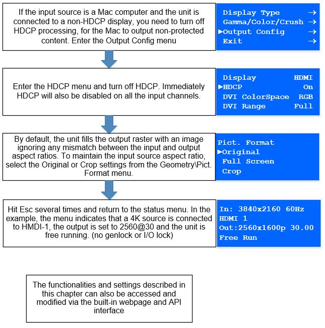
19 HDCP Output encryption When the input signal is HDCP encrypted, the DVI D, HDMI and HDBaseT outputs will also be encrypted and the 3G SDI output will be disabled. If the display device does not support HDCP, the output will be black and a message indicating that the presence of an HDCP signal will be shown on the screen The user can turn off the unit s HDCP compliance to allow non-encrypted content to pass through the unit. This is an important feature specially when using a MAC computer as the source. The MAC will encrypt its output signal if a compliant device is seen attached to its output regardless of the copy protection requirements of the content. By turning off HDCP, the MAC will see a non-compliant device and therefore will not encrypt its output. When HDCP compliance is turned off, encrypted sources will not be displayed.. 19
20 Audio Output Audio embedded in HDMI and SDI video streams is passed through the system and re embedded into the HDMI and SDI output signals. Also, the unit features a S/PDIF coaxial digital audio output connector for monitoring audio of the HDMI and SDI channel. When HDMI is selected as the input channel, the HDMI EDID is read by a video source such as a Blu Ray Player. The unit allows the source to provide the formats shown under output formats for HDMI in the below table. All formats are re embedded into the HDMI output data stream, those which are not allowed on the SDI or SPDIF output are muted on the individual channels. Output Channel HDMI SDI SPDIF Output Format PCM up to 8ch, up to 24Bit, up to 192kHz sampling rate (incl. 32kHz,44.1kHz,48kHz,96kHz,192kHz) PCM up to 8ch, up to 24Bit, 48kHz sampling rate PCM up to 2ch, up to 24Bit, up to 96kHz sampling rate (incl. 32kHz,44.1kHz,48kHz,96kHz) Analog Audio Units supporting audio include up to 8 analog stereo Inputs, two microphone Inputs with phantom power and an audio mixer. Analog stereo signals are connected to the unit via 3.5 mm jack sockets, except for the CV input that is associated with two RCA connectors. Using the audio menu, any video input can be link with any audio input and mixed with the mic inputs. Audio models also include stereo audio power amplifier supporting 15W RMS loudspeaker per output and separate stereo balanced line level audio outputs for external amplifier systems. The analog stereo outputs are available on two phoenix connectors. 20
21 4.5.5 Supported formats Horiz. Active Pixels Vert. Active Lines Vertical Refresh Rate (Hz) DVI HDMI HDBT Outputs 3G SDI Specification VESA DMT i p EIA/CEA 861 B Format 6 (NTSC) i EIA/CEA 861 B Format 17 (PAL) p VESA DMT VESA DMT EIA/CEA 861 B Format VESA CVT 001M9/VESA DMT VESA CVT 001MA/VESA DMT VESA DMT VESA DMT proprietary CVT 1.30MA/VESA DMT VESA CVT 001M3/VESA DMT VESA DMT VESA CVT 002MA i EIA/CEA 861 B Format p EIA/CEA 861 B Format VESA CVT 002MA R/VESA DMT proprietary proprietary EIA/CEA 861 F VIC= VESA CVT 004M R VESA CVT 004M R EIA/CEA 861 F VIC= EIA/CEA 861 F VIC=98 21
22 5. Unit Control All models can be controlled via the front panel, a web page built in into the unit or an API protocol interface. The next two chapters describe the Front Panel and Web Browser control methods. The API interface can be found in a separate document available on our web site. 6. Front Panel Control You can enter the main menu by pressing the Menu/Sel key from the status screen. You can use the jog wheel and Menu/Sel and Esc buttons to navigate through the different menus. A complete diagram of the menu tree is shown in Appendix A. The audio menu tree for units fitted with the audio option is shown in Appendix B. Next, is a brief description of the functions and settings available from the front panel menus. 6.1 Main Menu The main menu lists the selected input channel and 6 sub menus. The 6 sub menus are: Output Color Geometry Video Wall Enhancement System Each menu includes an Exit entry to return to the previous level. Some adjustments are not applicable to all signal types or operating modes, in which case those non applicable functions will be greyed out and are not accessible. The unit is designed to have separate memories for all the settings in each section. All Input parameters are specific to your chosen input channel and input signal type, and are not global to the unit. For example, if you change the settings for the composite video channel, you will not affect the settings you may have made in the DVI channel. 22
23 6.2 Input This menu provides an additional method of selecting the desired input. Depending on the specific model, some of these input selections may not be available. Test patterns can be selected even when there are no inputs connected to the unit. Different test patterns can be selected by scrolling the jog wheel. Settings: SDI 1 SDI 2 Display Port HDMI 1 HDMI 2 HDBaseT DVI HDMI 3 VGA YPbPr/RGB Composite Video Test Pattern Default : HDMI 1 23
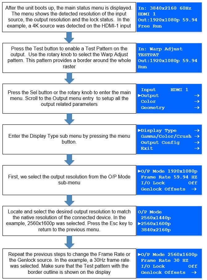
24 6.3 Output This menu contains adjustments related with the outputs of the unit Display Type Output Mode (Resolution) The selected output resolution should match the native resolution of the imaging device to avoid double scaling. The 3GSDI output does not feature the PC resolutions, only 480i/p, 576i/p, 720p and 1080i/p output modes are supported. Settings: See the Supported format table Default : 1920x1080p Frame Rate As with the output resolution, the output frame rate should match the native frame of the imaging device. Some frame rates may not be available depending on the selected resolution. In auto mode the output frame rate follows the input frame rate if it supported by the output resolution. If the input frame rate is not supported by the output resolution, then the unit determines the output frame according to a procedure programmed in the software. Settings: 60 Hz, Hz, 50 Hz, 48 Hz, 25Hz, 24 Hz, 23.97, Auto Default : 59.94Hz I/O Lock From this menu, the user can select the genlock mode of the unit. If I/O Lock is off, the output free runs with a fixed refresh rate determined by the frame rate setting. In this mode, the output vertical refresh sync deviates slightly from the input vertical refresh sync, even if both are set at the same rate, occasionally causing frame dropping or repeat. If I/O Lock is set to On, the output refresh rate follows the input video refresh rate if possible. If not, the output is operated with a fixed refresh rate determined by the frame rate setting. If I/O Lock is set to Genlock, the output refresh rate will follow the vertical sync of the signal connected to the Genlock BNC connector. Genlock is achieved when the Genlock vertical sync rate matches the vertical sync rate set in the output menu. Valid combinations are 50Hz/50Hz, 59.94Hz/59.94H and 60Hz/60Hz. If genlock is not achieved, the output frame rate refresh rate is determined by the frame rate setting. The LCD main status menu indicates the genlock status: (I/O Locked or Genlocked) or in free run mode (Free Run). In order to achieve clean switch between input selections, follow the locking settings described in the table below. 24
25 I/O Lock = On (Lock to i/p video) I/O Lock = Genlock I/O Lock = Off (Free Run) Auto Frame Rate Never Clean Always Clean Depends on Inputs Fixed Frame Rate (any) Never Clean Always Clean Always Clean If the output Frame rate is set to Auto, Genlock signals all genlock signals can be accepted. On the other hand, if a specific frame is selected, for example 60Hz, a Genlock reference signal od 60Hz can only be accepted and the unit will not lock to a 50Hz reference signal. If the output Frame rate is set to Auto and I/O lock is off, input switching may not be clean. Clean switching will depend how close the frame rates of the current and next input channel are. Settings: Off, On, Genlock (for models supporting genlock) Default : Off (Free Run) Frame Rate (Enable) From this menu the user can choose the output frame rates that the unit can output. This is done to prevent the unit from outputting frame rates that cannot be accepted by the display. Settings: 60 Yes/No, 50 Hz Yes/No, 48 Yes/No, 30/29.97Hz Yes/No, 25 Yes/No, 24/23.98 Yes/No Default : 60Hz Yes, 50Hz Yes, 48Hz No, 30/29.97Hz Yes, 25Yes, 24/23.98Hz Yes Gamma/Color Native Color Temp Native Color Temp allows the user to select from pre configured color temperatures to match the display. If this value is the same as the Color Temp value in the (Input) Color menu, no conversion is performed. Settings: 3700, 5500, 6500, 7500, 9300, Default : 6500K Output Gamma Output gamma allows to re gamma video signals with pre configured gamma values to match the display. Input gamma and output gamma both default to 2.2. If they are both set to the same value, there is no effect on the image. If you need to reduce the level of certain color in the image, select a higher value for the input color Temp in the Color menu, or a lower number for the Native Color Temp in the Output menu. Settings: 1.0 to 3.0 in steps of 0.1 Default :
26 6.3.3 Output Config Display Internally, the output interface processes data at a full ten bits per color. The color depth on the HDMI outputs is determined by the supported standard of the attached monitor or device when set to DVI/HDMI. DVI 1.0 and HDMI 1.1/1.2 devices are set at 24 bit, for HDMI 1.3 or later compliant devices it is up to 36 bit. The DVI forced selection will output video with 24 bit color depth irrespective of the supported standard of the attached monitor. Settings: DVI forced, DVI/HDMI Default : HDMI HDCP HDCP encryption support on the output can be switched off as is in the input. This means the unit pretends to be non HDCP compliant on the DVI/HDMI output port and consequently does not encrypt data. At the same time, HDCP is also turned off at the input ports. This allows the unit to accept non HDCP encrypted data. If the source however, is HDCP encrypted, then the output will be black. Settings: On, Off Default : On DVI Color Space and DVI Range When set to Default CEA, the output modes have limited range, and VESA modes have full range. Therefore, an incoming limited range mode is either passed through when the output is set to a CEA output mode or expanded when the output is set to a VESA mode. An incoming full range mode is either compressed when the output is set to a CEA output mode or passed through when the output is set to a VESA mode. If the HDMI/DVI output does not operate properly, the range can be changed manually. A limited video range is only using the following greyscale for video information 8 Bit System: 0x10.. 0xEF, 10 Bit System: 0x x03BF, 12 Bit System: 0x xEFF. Settings : Color Space: RGB or YPbPr / Range: Default, Limited, and Full Default : RGB & Full 26

27 6.3.4 Video Wall The Video Wall menu provides controls to set up multiple units in a multi screen application. Multiple screens are stitched together to provide a bigger display with higher resolution than a single display. Each display is driven by a separate unit. In a multi projection display, the individual projections typically are chosen to overlap to give seamless transitions. Multiple LED walls or LCD/Plasma screens do not have overlapping regions and the blend Width is set to zero. When using Video Wall to drive one single large screen, it is essential that all units are I/O locked or genlocked, otherwise motion tear will be observed at the boundaries of the image processed by each unit Auto Zoom Switches on the auto zoom resizing the video image to display the assigned part of the total image. When Auto zoom is turned on, the processor will cut and scale the portion of the picture selected by the matrix size. Settings: On/Off Default: Off Units Wide/Units High The dimensions of the multi screen display is defined with this menu. The maximum number of screen supported is 16. This function is used in conjunction with the next function. Settings: Units Wide: 1, 2, 3, 4 / Units High: 1, 2, 3, 4 Default: Units Wide: 1 / Units High: Horizontal Pos/Vertical Pos This setting provides the coordinates of the segment of the total image that the unit will process (cut out and resize). This function is used in conjunction with the previous function to select the blend regions to be provided even when auto zoom is turned off. Settings: 0 to 3 indicating co ordinates 0,0, to 3,3 for the maximum matrix size of 16 Default : 0, 0 In the example below a 4K image is split into four 1080p quadrants in a 2x2 configuration Enhancement 27
28 The enhancement menu provides image enhancement functions. Note that the enhancement settings apply only to video input signal and not to computer graphics signals Sharpness Control of the sharpening enhancement filters' levels. These are peaking filters to improve highfrequency response. Note that setting this control too high on a signal which already has good high frequency response will cause ringing or ghosting. Settings: 4 to 4 in steps of 1 Default : Detail This filter provides powerful 2D image enhancement which can be used to greatly improve detail definition and clarity without causing image ringing or ghosting. It improves both horizontal and vertical detail. Correct setting of the detail enhance filter can make SD signals look virtually indistinguishable from true HD. At setting 0 the filter is switched off, with setting 3 providing the highest effect. Settings: 0, 1, 2, 3 Default : 1 28
29 6.4 Color (Input Channel Adjustments ) Compass 3.0 Presentation Switcher Black Level Offset Used to select 7.5 IRE black level set up adjustment. Should always be set to 7.5 IRE for HDMI video and NTSC video inputs and should usually be off for PAL analog video inputs. Settings: 0 IRE, 7.5 IRE Default : 0 IRE Black Level Black level controls the offset applied to the video signal. (same as the brightness control on a TV) Settings: 50 to 50 in steps of 1 Default : Contrast Contrast controls the gain applied to the video signal. Settings: 50 to 50 in steps of 1 Default : Saturation Controls the video color saturation, (applies individually to all video inputs but not computer input signals or formats). Settings: 50 to 50 in steps of 1 Default : Hue Adjusts the color hue of NTSC signals. This is not applicable for computer input signals or formats. Settings: 50 to 50 in steps of 1 Default : 0 29
30 6.4.6 RGB values This is a user defined color temperature setting where R,G,B gain (white balance) and offset/bias (black balance) can be adjusted separately in order to match the display device. This control is not available for output modes with color space format YUV 4:2:0. Settings : Red/Green/Blue Gain/Bias : 512 to 512 Default : Color Temp A preset range of Color Temperature allowing the user to select from pre configured color temperatures to match the color temperature of the incoming signal. If this value Native Color Temp value in the Output menu are the same, no conversion is performed. Settings: 3700K, 5500K, 6500K, 7500K, 9300K, 10000K Default : 6500K Input Gamma Set this value to match the gamma of the input signal. Input and output gamma both default to 2.2. If they are both set to the same value, there is no effect on the image. Settings: 1.0 to 3.0 in steps of 0.1 Default :

.")
31 6.5 Geometry Compass 3.0 Presentation Switcher This menu contains adjustments associated with setting up position, aspect ratio and scale of the input signal Picture Format This menu allows users to select the displayed aspect ratio when the input signal aspect ratio is different to the display panel s aspect ratio. Some aspect ratios may not be applicable to all signal types, in which case selecting a non applicable aspect ratio conversion will have no effect on the displayed image. Original: Preserves the aspect ratio of the incoming image and scales the image to fit into the size of the panel. Depending on the aspect ratio of the panel the image is either bordered by the right/left side or bottom/top of the panel. Non used areas of the panel are displayed black (letterboxed). Full Screen: Scales the image to the size of the panel without preserving the aspect ratio. Crop: Preserves the aspect ratio and scales the image to fill the screen. Depending on the aspect ratio of the panel either the top/bottom or right/left areas of the image are cropped. Anamorphic: Scales the input image such that it is displayed with a 16:9 aspect ratio when displayed on the screen. The image is further scaled to fit into the size of the panel. Depending on the aspect ratio of the panel the image is then either bordered by the right/left side or bottom/top of the panel. Non used areas of the panel are displayed black (letterboxed). Settings: Original, Full Screen, Crop, Anamorphic Default: Original 31

32 6.5.2 Overscan Overscan is used to slightly zoom into the image. Therefore, the border area of an image is no longer displayed on the screen. This cuts off unwanted features at the top or bottom from e.g. head switching in legacy video images. Settings: 0 to 10 in steps of 1 Default: Pan Tilt Zoom (PTZ) This menu provides settings to zoom and shrink the image, pan horizontally and tilt vertically within the image. PTZ can be switched on or off and the settings can be saved per input channel or globally, i.e. if applied globally the same PTZ settings are applied when switching input channels or changing the input mode. The Zoom setting allows zooming into the image or shrink it. When Aspect Lock is set to On, vertical zoom is disabled and the horizontal zoom or shrink factor is also used to vertically adjust the image. In this mode the aspect ratio is preserved. When Aspect Lock is Off, horizontal and vertical scaling factors are set separately, regardless of the input image aspect ratio. Off raster panning is also allowed, i.e., the image can be shifted outside the active area of the display. The PTZ settings can be set to the default settings with the reset button. Settings: On/Off Default: Off 32
33 6.6 System This selection contains functions which are more applicable to system operation than to picture adjustment User Several unit settings can be stored under a user name. Different users can store their preferred settings and recall them by selecting their user name. User settings are stored automatically and no special action is required by the user. For example, if the setting is changed from USER1 to USER2, then all of unit s parameters at the time of the change will be stored under USER1. When the unit is changed back to USER1, the USER1 settings will be loaded back t the unit. Using the Web interface, any number of settings can also be stored/restored to/from the PC. Settings: USER 1, 2, 3, 4, 5, 6, 7, 8, 8, 10 Default : USER Names/Profiles The Names/Profiles menu provides input masks to rename the generic input channels and user names. User names and input channel names can be changed to any word with a maximum of 12 alpha numeric characters with a value range of 0 9, A Z and blank. The unit itself can be given a name. The default name is VIDEOPROC. This name followed by the MAC address is used by the web server and being displayed in the unit line of the web page Input Config Inputs can be configured through the following sub menus: Analog Inputs VGA Setup: Clock & Phase: Frequency (Clock) and phase can also be altered manually, as the vertical and horizontal position Settings: 0 to 32 Default : 0 Color Space Settings: RGB or YCbCr Default : RGB 33
34 The greyscale range can be reduced by switching from full to limited (see range values discussed in the output config section) Settings: Full / Limited Default : Full A reset button to factory defaults is provided, to return the phase, clock and positional settings to the original positions. The preferred video mode can be selected in the EDID Input Format menu. This setting can force the source to output a certain video mode provided the driver of the graphic card reads the preferred timing in the EDID. Most likely the PC needs to be rebooted for the driver to notice the EDID change. Default : 1920x1080p RGB/YPbPr Setup: Same as VGA Setup, except there is no concept of EDID with component video and thus no EDID Input Format menu. o CVBS Setup: CCS is a filter to reduce luminance to chrominance cross talk of composite video signals (only) which appears as a coarse rainbow pattern or random colors in regions of fine details. Default : On Digital Inputs DP Config: The automatic HDMI Color Space and Range settings can be overwritten in this menu. Color space Settings: RGB or YCbCr, if Auto setting does not give the desired result Default: Auto Range Settings: Limited. Full or Auto range. Default: Auto Settings: On/Off Default: Off Deep Color: The EDID can be configured to enable deep color capability. The unit can process color depth of 24/30 per channel. Deep Color can be off, if the source outputs 24bits, or set to on when the source outputs 30bits. The detected source output color depth is reported on the corresponding menu. 34
35 EDID In: The preferred video resolution can be selected in the EDID Input Format menu. This setting can force the source to output the selected format provided the driver of the graphic card takes notice of the preferred timing in the EDID. The PC most likely has to be rebooted for the driver to take notice. Default : 1920x1080p HDMI 1, HDMI 2, HDMI 2, DVI & HDBT Config. Color space Settings: RGB or YCbCr, if Auto setting does not give the desired result Default: Auto Range Settings: Limited. Full or Auto range. Default: Auto Deep Color: The EDID can be configured to enable deep color capability. The unit can process color depth of 24/30/36bit per channel. Deep Color can be off if the source outputs 24bit, or set to on if the source outputs either 30bit or 36bit. The detected source output color depth is reported on the corresponding menu. Settings: On/Off Default: Off EDID In: The preferred video resolution can be selected in the EDID Input Format menu. This setting can force the source to output the selected format provided the driver of the graphic card takes notice of the preferred timing in the EDID. The PC most likely has to be rebooted for the driver to take notice. Default : 1920x1080p HDCP: When setting HDCP Input to off, the unit pretends to be non HDCP compliant allowing the source to not encrypt data. The source will only non encrypt only when the material is not protected. When the HDCP capability is set to off, the output is unencrypted and this menu item is greyed out. Settings: On/Off Default: On DVI Config The preferred video mode for DVI input can be selected. This setting may force the source to output a certain video mode provided the driver of the graphic card takes notice of the preferred timing in the EDID. The PC most likely has to be rebooted for the driver to take notice. Settings: HDMI / DVI only Default: HDMI 35
36 HDMI Audio Support Settings: On/Off Default: On Compass 3.0 Presentation Switcher The audio capabilities of the HDMI port can be configured by means of overwriting the EDID. The unit described in this manual is part of an audio/video processing chain and devices behind the unit may not be able to cope with advanced audio. The unit can signal the source to match with the audio capabilities of the display (setting Match Display 1/2), or to be S/PDIF friendly or to be SDI friendly (48kHz PCM only, 2ch or 8ch). If the unit is set to Full the capabilities of the unit are communicated by means of the EDID to an audio source SDI Setup SDI audio input is routed to the HDMI and 3GSDI output connector. Two consecutive SDI audio channels can be output on the HDMI/3GSDI output interface. The group can be chosen. Or all eight SDI audio channels can be transmitted Settings: Stereo ch(1,2)/(3,4)/(5,6)/(7,8)/multichannel Default: Stereo ch (1,2) Level B Priority Since only one Level B signal can be processed by the unit, in this entry the user needs to prioritized the SDI input with the Level B signal. Settings: SDI1 / SDI2 Default: SDI SDI1/SDI2 Level B Stream Selects which of the two video streams (Stream 1 or 2) to use. Settings: SDI1(2) Level B Stream: Stream 1(2) Default: SDI1 Level B Stream: Stream 1 / SDI2 Level B Stream: Stream Test Pattern Setup When the menu is off, the test pattern can be selected by turning the jog wheel. For unit control through a web browser or to set up a certain default test pattern please use the input configuration menu. Custom test patterns loaded into the unit through the web interface, and selected as the other test patterns. Depending on the Output resolutions, test pattern images are resized dynamically by the software resolution to completely fit the output raster space. Available Test Patterns: o o o o Red Curtain Green Curtain Blue Curtain Grey V Bars 36
37 Default: Pattern: SMPTE o Grey H Bars o Aspect Test o Multi Test o Warp Adjust o SMPTE o PLUGE o Moving Cross o Custom 1 o Custom 2 o Custom 3 o Custom Test Pattern Tone A test tone can be set to accompany the test pattern Settings: On / Off Default: Off Color (FG) of the Moving Cross Compass 3.0 Presentation Switcher Settings: 0 to 7 6 = red; 7 = blue Default: 1 (White) 0 = black; 1 = white; 2 = yellow; 3 = cyan; 4 = green; 5 = magenta; Moving Cross Background (BG) color Settings: 0 to 8 0 to 8 ( 0 = black; 1 = white; 2 = yellow; 3 = cyan; 4 = green; 5 = magenta; 6 = red; 7 = blue; 8 = multicolour, sets the four quadrant colours as red, green, blue and black) Default: 8: (Multicolor) Moving Cross Speed Number of pixels that the test pattern moves per frame Settings: 1 to 10 Default: Moving Cross Width The width of the moving cross in pixels Settings: 4 to 40 Default: Input Enable Individual selections are provided to enable or disable each input 37
38 Settings: On or Off for each Input Default: All on Compass 3.0 Presentation Switcher Switching Transition: The switching transition can be selected to be Freeze, Blank, Fast Fade and Slow Fade. Freeze : Halts the prior channel image until the new channel image is stable. Freeze is the default mode. Blank : Switches the output to a black screen instead of the last shown image. Fast and Slow Fade : Fades between the channels with different transition times Settings: Freeze, Blank, Fast Fade and Slow Fade Default: Freeze Menu Settings This menu allows users to change the menu display time, i.e. the time after which the LCD menu is switched back to the main status screen again with no user interaction. From this menu you can change the language and also lock the keyboard. To unlock the keyboard a combination of keys has to be pressed at the same time. The locking of the keyboard is indicated by a message that the keypad is locked. The message also specifies the key press combination necessary to unlock the unit. When successfully unlocking the keypad the message shows up: Keypad unlocked. The backlight level of the LCD can be set in this menu. The background color of the web pages can be changed from dark to light to match the ambient conditions Language Settings: English (AE), English (BE), Deutsch Default: English (AE) Keypad Lock Settings: Off, Menu Only, All Keys Default: Lock: Off Menu Time Settings: 5, 10, 15, 20, 25, 30, Infinite Default: 15 secs LCD Backlight Settings: Default: Jog Push Enable Settings: On, Off Default: On 38
39 Web Colors Settings: Dark, Light Default: Dark 39
40 6.6.5 Network Settings The Network Settings menu allows users to configure the unit s TCP/IP address. Under Address Type a static or DHCP leased address can be chosen. The static address, gateway address and netmask needs to be entered manually. The Network Settings menu provides information on the DHCP Status and IP address assigned to the unit, as well as the fixed MAC Address programmed into the unit. The DHCP status can be Off when a static assignment is used. When DHCP is on, the menu displays the leased address. If the lease is unsuccessful, the menu displays none When changing from DHCP to Static mode or vice versa it is strongly recommended that you cycle the power to the unit in order the change is properly recognized by other devices on the network. Settings: Static, DHCP Default: DHCP Make sure you push the Apply button for the setting changes to become effective Security Settings The password for ftp and web access to the unit can be changed in this menu. FTP password Default: user WWW password : Off Factory Defaults This button allows users to restore all settings to the default values of the unit, allowing the unit to return to a known (good) system state. A confirmation is requested prior to actual system settings restore. 40
41 6.7 Audio This selection contains functions required to manage the audio inputs and outputs Mic 1,2 Level, Mix, Mute The Level setting defines the audio level for the Microphone inputs. Mix adjustment controls the mixing between Mic and the selected audio source. Settings: Level: 12 to +60 Mix : 0 to 100 (100 is full microphone sound) Mute: Yes, No Default : Level: 6 Mix : 50 Mute: No Balance, Treble, Bass Balance highlights the sound from the left or right output channels. Treble adjusts high frequency sounds and bass the low frequency sounds. Settings: Balance: 100 to +100 Treble : 15 to +15 Bass: 15 to +15 Default : Balance: 0 Treble : 0 Bass: Audio Setup Audio Delay This settings allows the users to adjust the delay between the video and audio sources. This feature is used to correct lip sync issues Settings: 100 to 500 ms Default : 0 ms Input Level Input level adjusts the gain of the incoming audio signal Settings: 12 to +6 db Default : 0 db Input Mode Defines whether the incoming audio signal is stereo and mono 41
42 Settings: Stereo / Mono Default : Stereo Compass 3.0 Presentation Switcher Input Mute Enables of the mute function for the selected audio source Settings: Yes / No Default : No Amp Gain Amp gain adjusts the gain for the D power amp driving speakers. Settings: 0 to +38 db Default : 0 db Audio Assign This menu allows users to assign any analog audio source or mics to the selected input. If the selected input is digital, the user can also select the audio that is embedded to the video signal. These selections can be performed on per input basis or globally Config Selects whether the Audio assignments are done per source or globally Settings: Per Inp / Globally Default : Per Inp Audio In This menu is enabled when the audio assignments are done globally. If an Analog source is selected, the user can also choose the analog audio source from the next menu (Analog In). If a Digital source is selected, the embedded audio in the selected audio source will be used. Settings: Stereo Analog / Analog with Mic / Digital Default : Stereo Analog Analog In This menu is enabled when the audio assignments are done globally. From this menu the user selects the audio source to be assigned to the selected input Settings: CVBS / HDBaseT / Display Port / HDMI 1 / HDMI 2 / VGA / DVI / HDMI 3 Default : CVBS Analog Inputs This menu is enabled when the audio assignments are done per Input. For each of the analog video sources the user can select a Stereo Analog source or a Stereo analog source with the mics. The user can also selected which of the analog source will be assigned to the input. 42
43 Settings: Stereo Analog / Analog with mic Default : Stereo Analog For the analog audio source: Settings: CVBS / HDBaseT / Display Port / HDMI 1 / HDMI 2 / VGA / DVI / HDMI 3 Default : The corresponding analog input associated with the video input Digital Inputs This menu is enabled when the audio assignments are done per Input. For each of the digital video sources the user can select a Stereo Analog source, a Stereo analog source with the mics, or the corresponding embedded audio within the video signal. If an analog source is selected, the user can also selected which of the analog source will be assigned to the input. Settings: Stereo Analog / Analog with Mic / Digital Default : Digital If an analog audio source is selected : Settings: CVBS / HDBaseT / Display Port / HDMI 1 / HDMI 2 / VGA / DVI / HDMI 3 Default : The corresponding analog input associated with the video input Mic Config This menu allows users to enable phantom power for condenser mics. When phantom power is enabled, a voltage of +48V is sent to the condenser microphone via the XLR socket Audio Out Mute This menu allows users to mute audio output source individually. 6.8 Status This menu provides status information of the connections to the HDMI2, DVI/HDMI1 and HDBT outputs. The unit reads the EDID of the attached monitor and makes decision based on its capabilities and the configuration of the unit (Deep Color and HDCP support). The type of attached monitor (DVI or HDMI), video bit depth (8, 10 or 12 bit per color channel) and HDCP encryption (on/off) is displayed. 43
44 7. Web Browser Control Compass 3.0 Presentation Switcher The unit can be remotely controlled from a PC or any mobile device. No additional software needs to be installed on the PC. The PC web browser is used as the graphical user interface for all control items. To connect to the unit the TCP/IP address of the unit has to be entered into the address list box of the web browser in the following format The TCP/IP address assigned to the unit can be found in the System/Network Settings menu. 7.1 Connecting to the unit The Network Settings menu of the unit allows to configure the unit s TCP/IP address. Under Address Type a static or DHCP leased address mode can be selected. he factory default of the unit is DHCP. The static address and Netmask needs to be entered manually. The Network Settings menu provides information on the DHCP Status and the IP address assigned to the unit as well as the fixed MAC Address of the unit. The DHCP status is Off when the static assignment is selected. If the unit has an assigned address, then the menu displays the address, or None if the lease was not successful. When changing from DHCP to Static mode or vice versa, it is strongly recommended that you cycle the power to the unit in order the change is properly recognized by other devices on the network After the correct IP address is entered into the address bar, the web browser starts to load the menus mirroring the status of the unit. All menu items are shown as their respective buttons, sliders and list boxes and can be accessed and altered with the PC mouse or corresponding navigational key presses. From the web Browser, under security settings, the user name and Password can be turned on. The default settings are: User Name: Password: user user 44

45 7.2 Web page menu Orientation Compass 3.0 Presentation Switcher The main page of the web browser is shown below. The Unit ID is displayed on the first line and is composed of the identifier followed by the MAC address. The firmware version number and information on the input mode are listed next. Under the information pane the available input channels are shown and can be activated directly. 45

46 The menu system can be navigated with the PC mouse. Move the mouse pointer over the menu item and click the left mouse button to open a submenu. Submenus have three dots followed by the menu name. Move the mouse pointer over the Back item and click the left mouse button to go back to the prior menu. Menu items can be lists, sliders or alpha numeric fields. A list item can be activated by moving the mouse pointer over the list item and clicking the left mouse button. The list comes up and an item can be selected by moving the mouse pointer to the desired value (here: 0 IRE) and clicking the left mouse button again. A slider value can be changed by moving the mouse pointer over the slider, click and hold the left mouse button and move the mouse to the right or left to decrease or increase the value. Also, the slider can be controlled in single steps with the mouse wheel. Or by moving the mouse pointer over the or + fields and clicking the left mouse button.. 46

47 Values can be entered directly in the field beneath the slider. Click into the field, enter the new value through the PC keyboard and click with the left mouse button to any location outside the field to update to the new value. Renaming the input channel is used as an example to explain the alpha numeric field changes. Move the mouse pointer into the alpha numeric field and click on the left mouse button. The cursor can be controlled with the right/left and back space keys of the PC keyboard. The new name for the input channel can be entered. The new name is stored when clicking with the left mouse button to any location outside the field. 47
 and select it. The path and name will be shown in the field left to the Browse button.")
48 7.3 Software Update A page for file uploads is provided. Browse a firmware file (extension.bin) and select it. The path and name will be shown in the field left to the Browse button. Now click the update button. 48

49 7.4 Backup and restore Compass 3.0 Presentation Switcher The unit set ups can be backed up to a PC and restored later through the web browser When pressing the Backup button a l file download dialog box appears. The default name of a backup is nvram.bin. This name can be changed and stored on the PC in any location. To restore the unit s settings, browse and select the file on your PC. The selected file will be shown in the field left to the Browse button. Now press the restore button. 49

50 7.5 LOGO & Custom Test Pattern Capture Compass 3.0 Presentation Switcher Any image in PNG format can be selected from your PC and loaded to the unit to be used as a LOGO. This name can be changed and stored on the PC in any location. The image size limitation is 64MB. From the same menu you can select up to four images and download them as custom test patterns. These images will appear as Custom1,2,3 or 4 in the Test pattern menu 50

51 8. Firmware Update The latest firmware is found on FSR s download website at: There are two methods of updating your unit s firmware. First, through a USB port with a USB memory drive and second, through TCP/IP connection with the web server. 8.1 USB update From the firmware dropdown menu, select the PV7S PQV6xx_HQU7xx_LED7xx 2\xxxx.bin file where XXXX is the latest firmware built number. Download the.bin file and rename it PV7update.bin Copy the file to the root directory of a USB memory stick Power Off the unit and plug the USB drive into one of the USB ports Power On the unit and wait few seconds for the message to remove the USB drive After the USB is removed, the unit will continue the boot up process. Wait until the boot up processes is completed, and the status menu appears on the front panel screen. The Status menu indicates the detected source, Output resolution and I/O lock state. 8.2 Web Browser update To update via the web server, please follow the steps outlined previously in the web browser control chapter. 51
52 9. ENVIRONMENTAL AND EMC 9.1 Recommended Operating Conditions Temperature 0 o C to 40 o C Humidity (non condensing) 5% to 95% 9.2 Storage Temperature 25 o C to +85 o C Humidity 0% to 95% 9.3 CE and FCC Compliance CE: This product complies with the requirements of 2004/108/EC Electromagnetic Compatibility Directive, and 2006/95/EC Low Voltage Directive. Compliance is to EN55022 Class A. FCC: WARNING: This equipment has been tested and found to comply with the limits for a Class A digital device pursuant to Part 15 of the FCC Rules. These limits are designed to provide reasonable protection against harmful interference when the equipment is operated in a commercial environment. This equipment generates uses and can radiate radio frequency energy and, if not installed and used in accordance with the instruction manual, may cause interference to radio communications. Operation of this equipment in a residential area is likely to cause interference in which case the user will be required to correct the interference at their own expense. The user is cautioned that changes and modifications made to the equipment without approval of the manufacturer could void the user s authority to operate this equipment. It is suggested that the user use only shielded and grounded signal cables to ensure compliance with FCC rules. 52
53 9.4 PAT Testing Earth continuity testing under PAT regulations shall be done to the product with 8A or 10A only. A test with 25A may damage the product. Since the unit is classified as an IT equipment, according to the IEE Code of Practice, the test can also be performed with mA. If this method is not available, and a high current test is to be used instead, a 8A or 10A test is also acceptable (a minimum of 1.5 times of the unit s internal 5A fuse). You have to be careful where you connect the earth bond test lead when using 8A or 10A. Always connect the test lead (mains earth) to the metal chassis. DO NOT CONNECT to the connectors of the rear panel (signal earth), because you may damage the unit beyond repair. 53
54 Volume Input Output APPENDIX A Front Panel Menu Tree Structure db 3GSDI 1 2 3GSDI 2 2 DisplayPort HDMI 1 HDMI 2 HDBT 1 VGA DVI CV RGB/YPbPr HDMI 3 TP LOGO Compass 3.0 Presentation Switcher Volume adjustment is only available in the Audio models. For the complete Audio Menu, refer to the next section Factory Defaults HDMI 1 Display Type O/P Mode 1920x1080p 640x480p x2160p Frame Rate 59.94Hz 23.98Hz... 60Hz I/O Lock Off Off Source Genlock Genlock Offsets H Offset V Offset Frame Rates Yes No Gamma/ Color/ Crush Native Color 6500K 3700K 5500K 6500K 7500K 9300K 10000K Output Gamma Black Crush steps Output Config Display DVI/HDMI HDMI DVI Forced HDCP On On Off DVI Colorspace RGB RGB YPbPr DVI Range Full Full Limited Auto 1 HDBT models: CO PS91, CO PS91A, CO PS111, CO PS111A 2 SDI/Genolock Models: CO PS101, CO PS101A, CO PS111, CO PS111A 54
55 Output Color Factory Defaults Video Wall Auto Zoom Off Off On Units Wide 1 1,2,3,4 Units High 1 1,2,3,4 H Position 0 0,1,2,3 V Position 0 0,1,2,3 Bezel Width L(eft) Bezel 0 0 pxls... 50pxls R(ight) Bezel 0 0 pxls... 50pxls T(op) Bezel 0 0 pxls... 50pxls Bot(tom) Bezel 0 0 pxls... 50pxls Wall Setup Std Standard Advanced Adv. Wall Setup Wall Width 0 pxls pxls Wall Height 0 pxls pxls Hor Offset 0 pxls pxls Input Channel Adjustments Ver Offset 0 pxls pxls BL Offset 0 IRE 0 IRE 7.5 IRE Black Level steps Contrast steps Saturation steps Hue steps RGB Values Red Bias Red Gain Green Bias Green Gain Blue Bias Blue Gain HDBT models: CO PS91, CO PS91A, CO PS111, CO PS111A 2 SDI/Genolock Models: CO PS101, CO PS101A, CO PS111, CO PS111A 55
56 Color Factory Defaults Color Temp 6500K 3700K 5500K 6500K 7500K 9300K 10000K Input Gamma Geometry Enhancement Pict. Format Full Screen Original Full Screen Crop Anamorphic Theaterscope Overscan 0 Input Channel(s) 0%.. 10% Adjustments Pan/Tilt/Zoom PTZ Enable Off Off On PTZ Setting Global Global Use per mode Pan 0 50%... 50% Tilt 0 50%... 50% Zoom H 0 25%...400% Aspect Lock On Zoom V Off On Enabled when Aspect Lock is Off 0 25%...400% PTZ Reset Sharpness steps Details steps 1 HDBT models: CO PS91, CO PS91A, CO PS111, CO PS111A 2 SDI/Genolock Models: CO PS101, CO PS101A, CO PS111, CO PS111A 56
57 System Factory Defaults User User 1 User1... User10 Names/Profiles Unit Name Input Names 3GSDI 1 2 Input Config User Names Analog Inputs 3GSDI 2 2 DisplayPort HDMI 1 HDMI 2 HDBT 1 VGA DVI CV RGB/YPbPr HDMI 3 TestPattern LOGO User 1...User 10 VGA Setup RGB/YPbPr Setup CVBS Setup Clock 0 Phase steps ColorSpace RGB RGB YCbCr Auto Range Full Full Limited Auto Reset Mode EDID IN 1920x1080p x1080p x2160p60 Clock 0 Phase steps H Position 0 0 V Position 0 0 ColorSpace RGB RGB YCbCr Auto Range Full Full Limited Auto Reset Mode CCS On Off / On 1 HDBT models: CO PS91, CO PS91A, CO PS111, CO PS111A 2 SDI/Genolock Models: CO PS101, CO PS101A, CO PS111, CO PS111A 57
58 System Input Config Digital Inputs DP Config HDMI 1 Config HDM 2 Config HDBT Config 1 DVI Config HDMI 3 Config HDMI Audio SDI Setup 2 Factory Defaults Colorspace RGB RGB YCbCr Range Auto Auto Full Limited Deep Color Auto Auto On Off EDID In 1920x1080p x1080p x2160p60 HDCP On On Off Full Full Match Display 1 Match Display 2 S/PDIF friendly SDI friendly 2 ch SDI friendly 8 ch Audio Map Level B priority SDI 1 Level B Stream SDI 2 Level B Stream Stereo ch(1,2) Stereo ch(3,4) Stereo ch(5,6) Stereo ch(7,8) Multichannel Stereo ch(1,2) SDI 1 SDI 1 SDI 1 Stereo ch(1,2) Stream 1 Stream 1 Stream 2 SDI 1 Stream 1 SDI 1 1 HDBT models: CO PS91, CO PS91A, CO PS111, CO PS111A 2 SDI/Genolock Models: CO PS101, CO PS101A, CO PS111, CO PS111A 58
59 System Input Config Test Pattern Setup Test Pat. Input Enable Switching Test Tone FG Color BG Color 3GSDI 1 2 3GSDI 2 2 DisplayPort HDMI 1 HDMI 2 HDBT 1 VGA DVI CV RGB/YPbPr HDMI 3 TP LOGO Freeze Blank Fast Fade Slow Fade Red curtain Green curtain Blue curtain Grey V bars Grey H bars Aspect Test Multi Test Warp Adjust SMPTE PLUGE Custom Logo On / Off Black White Yellow Cyan Green Magenta Red Blue Red Blue Multi On Off Factory Defaults SMPTE Off White Multi On Freeze 1 HDBT models: CO PS91, CO PS91A, CO PS111, CO PS111A 2 SDI/Genolock Models: CO PS101, CO PS101A, CO PS111, CO PS111A 59
60 System Factory Defaults Menu Settings Language English (AE) English (AE) English (BE Deutsch Keypad Lock Off Off Menu Only All Keys Menu Time 30 sec 5 sec 10 sec 15 sec 20 sec 25 sec 30 sec Infinite LCD Backlight Jog Push Enable On On Off Web Colors Dark Dark Light Network Settings Address Type DHCP DHCP Static IP NET GW Apply Security Settings FTP Passwd user user WWW Passwd Off On Off Factory Defaults Cancel Factory Defaults Audio Status HDMI DVI HDBT HDCP Bit Depth 8,10,12 HDCP Bit Depth 8,10,12 HDCP Bit Depth 8,10,12 A complete Audio menu is available for the Audio models. For the complete menus, refer to the next section 1 HDBT models: CO PS91, CO PS91A, CO PS111, CO PS111A 2 SDI/Genolock Models: CO PS101, CO PS101A, CO PS111, CO PS111A 60
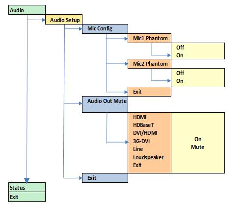
61 APPENDIX B Front Panel Audio Menu Tree Structure 61
62 Volume Input Output Color Geometry Video Wall Enhancement System Audio db Mic1 Level Mic1 Mix % Mic1 Mute No/ Yes Mic2 Level db ` Mic2 Mix % Mic2 Mute No/ Yes Balance Treble Bass Audio Setup next page Audio Delay Input Level Input Mode Input Mute Amp Gain Audio Assign ms db Stereo Mono No Yes Config Audio In Per Input Global Stereo Analog Analog with Mics Digital 62
63 Audio Audio Setup Audio Assign Analog In CVBS HDBaseT Display Port HDMI 1 HDMI 2 VGA DVI HDMI 3 Analog Inputs VGA Audio Stereo Analog Analog with Mics Digital VGA Analog CVBS HDBaseT Display Port HDMI 1 HDMI 2 VGA DVI HDMI 3 RGB/YPbPr RGB/YPbPr Analog Stereo Analog Analog with Mics Digital CVBS HDBaseT Display Port HDMI 1 HDMI 2 VGA DVI HDMI 3 CVBS Audio Stereo Analog Analog with Mics Digital CVBS Analog CVBS HDBaseT Display Port HDMI 1 HDMI 2 VGA DVI HDMI 3 Exit next page 63
64 64
65 Audio Audio Setup Audio Assign Digital Inputs SDI1 Audio SDI1 Analog Stereo Analog Analog with Mics Digital CVBS HDBaseT Display Port HDMI 1 HDMI 2 VGA DVI HDMI 3 SDI2 Audio Stereo Analog Analog with Mics Digital SDI2 Analog CVBS HDBaseT Display Port HDMI 1 HDMI 2 VGA DVI HDMI 3 DP Audio Stereo Analog Analog with Mics Digital DP Analog CVBS HDBaseT Display Port HDMI 1 HDMI 2 VGA DVI HDMI 3 HDMI1 Audio Digital Analog with Mics Digital HDMI1 Analog CVBS HDBaseT Display Port HDMI 1 HDMI 2 VGA DVI HDMI 3 next page 65
66 66
67 Audio Audio Setup Audio Assign Digital Inputs HDMI2 Audio HDMI2 Analog Stereo Analog Analog with Mics Digital CVBS HDBaseT Display Port HDMI 1 HDMI 2 VGA DVI HDMI 3 HDBT Audio HDBT Analog Stereo Analog Analog with Mics Digital CVBS HDBaseT Display Port HDMI 1 HDMI 2 VGA DVI HDMI 3 HDMI3 Audio Stereo Analog Analog with Mics Digital HDMI3 Analog CVBS HDBaseT Display Port HDMI 1 HDMI 2 VGA DVI HDMI 3 DVI Audio Digital Analog with Mics Digital DVI Analog CVBS HDBaseT Display Port HDMI 1 HDMI 2 VGA DVI HDMI 3 Exit next page Exit 67
68 68

69 APPENDIX C Single Link DVI-U Pinout Pin 1 TMDS data 2 Digital red Pin 2 TMDS data 2+ Digital red+ Pin 3 TMDS data 2/4 shield Pin 4 TMDS data 4 Pin 5 TMDS data 4+ Pin 6 DDC clock Pin 7 DDC data Pin 8 Analog vertical sync Pin 9 TMDS data 1 Digital green Pin 10 TMDS data 1+ Digital green+ Pin 11 TMDS data 1/3 shield Pin 12 Pin 13 Pin V Power for monitor when in standby Pin 15 Ground Return for pin 14 and analog sync Pin 16 Hot plug detect Pin 17 TMDS data 0 Digital blue and digital sync Pin 18 TMDS data 0+ Digital blue+ and digital sync Pin 19 TMDS data 0/5 shield Pin 20 Pin 21 Pin 22 TMDS clock shield Pin 23 TMDS clock+ Digital clock+ Pin 24 TMDS clock Digital clock C1 Analog red C2 Analog green C3 Analog blue C4 Analog horizontal sync C5 Analog ground Return for R, G, and B signals 69

70 APPENDIX C RS-232 Pinout Pin 2 Received Data Pin 3 Transmit Data Pin 5 Signal Ground 70
VP-796(A)(ASV) / VP-797A(ASV) / VP-798ASV. User s Manual
(ASV) / VP-797A(ASV) / VP-798ASV. User s Manual") VP-796(A)(ASV) / VP-797A(ASV) / VP-798ASV User s Manual COPYRIGHT This document and the software described within it are copyrighted with all rights reserved. Under copyright laws, neither the documentation
VP-796(A)(ASV) / VP-797A(ASV) / VP-798ASV User s Manual COPYRIGHT This document and the software described within it are copyrighted with all rights reserved. Under copyright laws, neither the documentation
PS200 PS200T PS300T 4K Scalers-Switchers. User s Manual
 PS200 PS200T PS300T 4K Scalers-Switchers User s Manual This page is intentionally left blank 2 COPYRIGHT This document and the software described within it are copyrighted with all rights reserved. Under
4K Presentation switcher-scaler Chameleon PS200/300 series 2017
 4K Presentation switcher-scaler Chameleon PS200/300 series 2017 Chameleon PS200/300 series HQUltra technology was chosen by the European Broadcast Union for frame rate and standards conversion of the recent
USER MANUAL. DV-HSW-41 HDMI 4x1 SWITCHER LIT Bergen Boulevard, Woodland Park, NJ Tel FAX Web
 USER MANUAL DV-HSW-41 HDMI 4x1 SWITCHER 244 Bergen Boulevard, Woodland Park, NJ 07424 Tel 973-785-4347 FAX 973-785-3318 Web www.fsrinc.com LIT1372 PROPRIETARY INFORMATION All information in this manual
LEDView510 and LEDView530 Operating Instructions
 LEDView510 and LEDView530 Operating Instructions Version 2.20 IMPORTANT NOTICE: When using extreme shrink to drive a single or few LED modules the OSD menu of LEDView may become hardly readable - including
OPERATING GUIDE. HIGHlite 660 series. High Brightness Digital Video Projector 16:9 widescreen display. Rev A June A
 OPERATING GUIDE HIGHlite 660 series High Brightness Digital Video Projector 16:9 widescreen display 111-9714A Digital Projection HIGHlite 660 series CONTENTS Operating Guide CONTENTS About this Guide...
User Manual. Model 1365 Video Scaler
 User Manual Model 1365 Video Scaler Model 1365 PC/HD Video Converter Table Of Contents 1.0 Introduction........................3 2.0 Specifications....................... 4 3.0 Checking Package Contents................5
HQView-500 Series Operating Instructions
 HQView-500 Series Operating Instructions Version 2.40 This manual explains how to operate your HQView-500 Series (HQView-5xx) image scaler. The HQView-500 Series comes in four versions HQView-500S, HQView-510,
VENUS X1PRO-E Quick Start
 VENUS X1PRO-E Quick Start 4K input support in DP, HDMI and Dual Link DVI Support 8K x 1K, 4K x 2K Seamless Splicing EDID management Modular 2K input: Three slots for 2K input options 2K-2K and/or 4K-2K
USER MANUAL MODEL: VP-792 Warp and Blend Scaler
 KRAMER ELECTRONICS LTD. USER MANUAL MODEL: VP-792 Warp and Blend Scaler VP-792 Operating Instructions Version K 1.4 This manual explains how to operate your VP-792 warp and blend scaler. VP-792 is designed
User Manual DV-HDSS-41-TX. 4x1 4K Scaling Presentation Switcher with Dual Outputs. NOTE: See FSR LIT1628 API manual for serial commands.
 User Manual DV-HDSS-41-TX 4x1 4K Scaling Presentation Switcher with Dual Outputs NOTE: See FSR LIT1628 API manual for serial commands. 43153 LIT1627 Important Safety Instructions. Table of Contents Important
User Manual HD-HAUD-SP-RX. 100m HDBaseT HDMI Receiver
 User Manual HDHAUDSPRX 100m HDBaseT HDMI Receiver 244 Bergen Boulevard, Woodland Park, NJ 07424 Tel 9737854347 FAX 9737853318 Web: www.fsrinc.com 43084 LIT1541 Important Safety Instructions Contents are
SIERRA VIDEO SP-14 SETUP GUIDE. User s Manual
 SIERRA VIDEO SP-14 SETUP GUIDE User s Manual SP-14 Setup Guide Version S 1.0 1 Contents Introduction 3 The Basic System 4 Flexible Connectivity 5 Control via Front Panel Buttons 6 Set Scaler Functions
VSP 168HD Quick Start
 VSP 168HD Quick Start Support 10Gbps of transmission rate Support HDBaseT protocols and standards Support USB upgrade Max 2048 1152@60Hz/2560 816 60Hz input/output resolution Support custom output resolution
User Manual rev: Made in Taiwan
 CV-500S HDMI to Component/CVBS & Audio Scaler Converter User Manual rev: 131218 Made in Taiwan The CV-500S HDMI to Component/CVBS & Audio Scaler Converter has been tested for conformance to safety regulations
Warranty and Registration. Warranty: One Year. Registration: Please register your product at Port, or. or Windows.
 7 7 Port, or or Windows Port Warranty and Registration Warranty: One Year Registration: Please register your product at www.aitech.com 2007 AITech International. All rights reserved. WEB CABLE PLUS PC-TO-TV
CONTENT Product Introduction... 2 Packing Configuration...3 Hardware Orientation... 4 Front Panel... 4 Back Panel... 6 Using Your Product... 7 Content
 VENUS X1PRO Quick Start 4K input support in DP, HDMI and DVI Input standard 2K formats Scale and switch seamlessly between 2K and 4K inputs Output to any format 2K or 4K EDID management on board HDCP 2.0
User Manual. PC / HD Scaler. with advanced video processing. VGA to Component Video Component Video to VGA VGA to VGA Component to Component
 User Manual PC / HD Scaler with advanced video processing VGA to Component Video Component Video to VGA VGA to VGA Component to Component Model 1366 WARNINGS Read these instructions before installing or
USER MANUAL MODEL: VP-793 Warp-Blend
 KRAMER ELECTRONICS LTD. USER MANUAL MODEL: VP-793 Warp-Blend VP-793 Operating Instructions Version K1.3 This manual explains how to operate your VP-793 warp-blend scaler. VP-793 is designed to provide
USER MANUAL. DV-HXT-2 HDMI to CAT5e /6 EXTENDERS LIT1374
 USER MANUAL DV-HXT-2 HDMI to CAT5e /6 EXTENDERS 244 Bergen Boulevard, Woodland Park, NJ 07424 Tel 973-785-4347 FAX 973-785-3318 Web www.fsrinc.com LIT1374 Proprietary Information All information in this
HQView-325 Operating Instructions
 HQView-325 Operating Instructions This manual explains how to operate your HQView-325 image scaler. HQView-325 is designed to provide users with a powerful and flexible method of driving large display
Operation Manual 1T-TG-PCHD Analog Test Generator 1T-TG-DVI DVI Test Generator
 99 Washington Street Melrose, MA 02176 Phone 781-665-1400 Toll Free 1-800-517-8431 Visit us at www.testequipmentdepot.com Operation Manual 1T-TG-PCHD Analog Test Generator 1T-TG-DVI DVI Test Generator
C / C / C Scaling with Speed and Agility
 C2-2855 / / Scaling with Speed and Agility A new generation of Scalers tvone s evolutionary development of our renowned CORIO 2 scaler technology continues to provide commercial integrators with unsurpassed
User Manual. PTN Electronics. SC121D-TN Scaler Switcher, with Digital Amplifier. Please read this manual carefully before using this product.
 PTN Electronics SC121D-TN Scaler Switcher, with Digital Amplifier User Manual SC Series --- Presentation Scaler Switcher Please read this manual carefully before using this product. l Content table 1.
VSP 9516S Quick Start
 VIEWSIZE THE WORLD VSP 9516S Quick Start Max 2048 1152@60Hz/2560 816 60Hz input/output resolution User-defined resolution adjustment Picture in picture Audio and video sync Seamless switching between inputs
PRO-ScalerHD2V HDMI to VGA & Audio Scaler Converter. User s Guide. Made in Taiwan
 PRO-ScalerHD2V HDMI to VGA & Audio Scaler Converter User s Guide Made in Taiwan Congratulations for owning a gofanco product. Our products aim to meet all your connectivity needs wherever you go. Have
LEDView530 Operating Instructions
 LEDView530 Operating Instructions Version 2.46 IMPORTANT NOTICE: When using extreme shrink to drive a single or few LED modules the OSD menu of LEDView may become hardly readable - including the assigned
Marshall Electronics. Pro A/V Communications VMV-402-SH. 3G/HD/SD-SDI Quad-viewer/Switcher with Audio Meter Display. User Manual.
 Marshall Electronics Pro A/V Communications VMV-402-SH 3G/HD/SD-SDI Quad-viewer/Switcher with Audio Meter Display User Manual Table of Contents 1. Introduction... 3 2. Features... 3 3. Package Contents...
SUPERSCALE Multi-Format to HDMI Scaler
 SUPERSCALE Multi-Format to HDMI Scaler Operation Manual DISCLAIMERS The information in this manual has been carefully checked and is believed to be accurate. SPATZ assumes no responsibility for any infringements
C / C / C Scaling with Speed and Agility
 / / Scaling with Speed and Agility A new generation of Scalers tvone s evolutionary development of our renowned CORIO 2 scaler technology continues to provide commercial integrators with unsurpassed image
MaxView Cinema Kit Quick Install Guide
 SYSTEM SETUP The MaxView will work at any of the following display settings: INSTALLATION MaxView Cinema Kit Quick Install Guide Step 1 - Turn off your computer. Disconnect your monitor s VGA cable from
AtlonA HDMI Media Center 6 inputs 1 output Switcher & Converter & 1080p Up-Scaler AT-LINE-EX. User Manual
 AtlonA HDMI Media Center 6 inputs 1 output Switcher & Converter & 1080p Up-Scaler AT-LINE-EX User Manual TABLE OF CONTENTS 1. Introduction... 1 2. Features... 1 3. Package Contents... 1 4. Operation Controls
CORIO master C3-540 Series
 Key Features Manage up to 4 independent video walls Uses CORIOgrapher; simple, powerful software interface Universal DVI Inputs/Outputs: (HDMI/CV/YC/RGB/YPbPr) SDI Inputs/Outputs: SD/HD-SDI/3G-SDI to 1080p60
3GSDI to HDMI 1.3 Converter
 3GSDI to HDMI 1.3 Converter EXT-3GSDI-2-HDMI1.3 User Manual www.gefen.com ASKING FOR ASSISTANCE Technical Support: Telephone (818) 772-9100 (800) 545-6900 Fax (818) 772-9120 Technical Support Hours: 8:00
PRO-HDMI2HD. HDMI to SDI/3G-HD-SD Converter. User Manual. Made in Taiwan
 PRO-HDMI2HD HDMI to SDI/3G-HD-SD Converter User Manual Made in Taiwan rev.1008 103 Quality Circle, Suite 210 Huntsville, Alabama 35806 Tel: (256) 726-9222 Fax: (256) 726-9268 Email: service@pesa.com Safety
User Manual TL-2X1-HDVC 2x1 HDMI & VGA Switcher with Control All Rights Reserved Version: TL-2X1-HDVC_160630
 User Manual TL-2X1-HDVC 2x1 HDMI & VGA Switcher with Control All Rights Reserved Version: TL-2X1-HDVC_160630 Preface Read this user manual carefully before using this product. Pictures shown in this manual
5x2 4K60 Presentation Switcher with HDMI and HDBaseT output
 5x2 4K60 Presentation Switcher with HDMI and HDBaseT output VER 1.0 Thank you for purchasing this product For optimum performance and safety, please read these instructions carefully before connecting,
MX-1004P. Professional Quad-View Video Processor. User Manual. Made in Taiwan
 MX-1004P Professional Quad-View Video Processor User Manual Made in Taiwan Safety and Notice The MX-1004P Professional Quad-View Video Processor has been tested for conformity to safety regulations and
J6 User Manual. User Manual. Multi-Screen Splicing Processor J6. Xi an NovaStar Tech Co., Ltd. Rev1.0.1 NS
 J6 User Manual User Manual Multi-Screen Splicing Processor J6 Rev1.0.1 NS160110162 Statement Dear users, You are welcome to use the J6, a multi-screen splicing processor of Xi'an NovaStar Tech Co., Ltd.
CP-255ID Multi-Format to DVI Scaler
 CP-255ID Multi-Format to DVI Scaler Operation Manual DISCLAIMERS The information in this manual has been carefully checked and is believed to be accurate. Cypress Technology assumes no responsibility
AVG-SC121D-T. Features
 The AVG-SC121D-T is a full HD scaler switcher with 12 video, 6 audio & 2 MIC inputs. It scales & switches HDMI, VGA, YPbPr, C-Video & S- video to HDBaseT, HDMI & VGA simultaneously, and audio to a 2x20W
PC/HDTV 2-Way Converter
 Vision for Net Media HDView PC/HDTV 2-Way Converter Operation Manual 1. Introduction The HDView is a high-performance universal PC/HDTV to PC/HDTV converter. It combines the functions of a video scaler,
A/V Cinema Scaler Pro II
 A/V Cinema Scaler Pro II EXT-AVCINEMAAD User s Manual ASKING FOR ASSISTANCE Technical Support: Telephone (818) 772-9100 (800) 545-6900 Fax (818) 772-9120 Technical Support Hours: 8:00 AM to 5:00 PM Monday
Instruction Guide. The TV Jockey Computer Monitor TV Tuner with Remote COMP2VGATVGB. The Professionals Source For Hard-to-Find Computer Parts
 VIDEO ADAPTER The TV Jockey Computer Monitor TV Tuner with Remote COMP2VGATVGB Instruction Guide * Actual product may vary from photo The Professionals Source For Hard-to-Find Computer Parts FCC COMPLIANCE
CSLUX-300I Multi-Format to HDMI Scaler
 CSLUX-300I Multi-Format to HDMI Scaler Operation Manual DISCLAIMERS The information in this manual has been carefully checked and is believed to be accurate. Cypress Technology assumes no responsibility
VSP 198CVS Quick Start
 VIEWSIZE THE WORLD VSP 198CVS Quick Start Max 2048 1152@60Hz/2560 1152 50Hz input/output resolution User customize output resolution 3G/HD/SD-SDI input Multiple cascade mapping for super resolution DVI
P XGA TFT Monitor. User s Manual
 P6151 15 XGA TFT Monitor User s Manual Disclaimers This manual has been carefully checked and believed to contain accurate information. Axiomtek Co., Ltd. assumes no responsibility for any infringements
Product Catalog. Route - Transport - Extend - Convert - Scale. Multimedia Products for HDMI and DVI. 3G sdi OCT-2010-C
 Product Catalog Route - Transport - Extend - Convert - Scale Multimedia Products for HDMI and DVI 3G sdi OCT-2010-C Quick Reference Guide RS-232 INPUT 2 INPUT 4 OUTPUT 2 OUTPUT 4 OUTPUT 6 OUTPUT 8 INPUT
VSP 516S Quick Start
 VIEWSIZE THE WORLD VSP 516S Quick Start Max 2048 1152@60Hz/2560 816 60Hz input/output resolution User customize output resolution 3G/HD/SD-SDI input Multiple cascade mapping for super resolution Seamless
RMS 8424S Quick Start
 VIEWSIZE THE WORLD RMS 8424S Quick Start Standard 4 unit rack mount size 8 inch LCD 2 1024 3 (RGB) 600 16:9 / 4:3 adjustable SDI/HDMI embedded audio output via 3.5mm earphone socket Support SDI/DVI audio
Cablesson HDelity 7.1ch Audio Extractor & Mixer. User Manual
 Cablesson HDelity 7.1ch Audio Extractor & Mixer User Manual All rights reserved - CABLESSON All rights reserved - CABLESSON ! SAFETY AND NOTICE The Cablesson HDelity HDMI 7.1ch Audio Extractor and Mixer
CSLUX-300 Multi-Format to HDMI Scaler
 CSLUX-300 Multi-Format to HDMI Scaler Operation Manual DISCLAIMERS The information in this manual has been carefully checked and is believed to be accurate. Cypress Technology assumes no responsibility
SC-HD-2A HDMI Scaler & Audio Embedder / Extractor
 User s Manual SC-HD-2A HDMI Scaler & Audio Embedder / Extractor Scale HDMI or DVI video Embed Digital or Analog Audio into HDMI output Extract (De-embed) Digital and Analog Audio from HDMI input UMA1246
Multi-Format AV Scaler with DisplayPort
 AVSC-7DA-HDMI Product Data Sheet Multi-Format AV Scaler with DisplayPort Basic Features Compliant with HDCP 2.0. Input support: Analog: analog video, S-Video, composite video, VGA; Digital: DVI, HDMI,
Modular Video Wall Controller
 Modular Video Wall Controller Feb.12th, 2017 Table of content INTRODUCTION...1 Availability and Reliability... 2 Robustness... 3 Easy Expansion...4 Powerful Video and Image Processing...4 4K Ultra HD Support...4
CP 3072S Quick Start
 VIEWSIZE THE WORLD CP 3072S Quick Start 4 channels, 16 signal sources Preview and program outputs separately PIP between any two inputs Seamless switching between any two channels Seamless switching between
PremierViewProHD-LED Operating Instructions
 PremierViewProHD-LED Operating Instructions This manual explains how to operate your PremierViewProHD-LED (PVProHD-LED) image scaler. The PVProHD-LED is designed to provide users with a powerful and flexible
CSLUX-300I Multi-Format to HDMI Scaler
 CSLUX-300I Multi-Format to HDMI Scaler Operation Manual SAFETY PRECAUTIONS Please read all instructions before attempting to unpack, install or operate this equipment and before connecting the power supply.
Table of Contents FCC COMPLIANCE STATEMENT... 4 WARNINGS AND PRECAUTIONS... 4 WARRANTY... 5 STANDARD WARRANTY... 5 TWO YEAR WARRANTY... 5 DISPOSAL...
 1 Table of Contents FCC COMPLIANCE STATEMENT... 4 WARNINGS AND PRECAUTIONS... 4 WARRANTY... 5 STANDARD WARRANTY... 5 TWO YEAR WARRANTY... 5 DISPOSAL... 6 1. INTRODUCTION... 7 FEATURES... 7 2. CONNECTIONS
User Manual. Multi-Screen Splicing Processor J6
 User Manual Multi-Screen Splicing Processor J6 Rev1.0.0 NS160100147 Statement Dear users, Welcome to use the J6, a multi-screen splicing processor. This manual is intended to help you to understand and
G406 application note for projector
 G406 application note for projector Do you have trouble in using projector internal warp and edge blending function? Inconvenient in multiple signal source connection System resolution is not enough after
Zigen ZIG-ADM. 4K UHD+ Dolby Digital & DTS Stereo Decoder. 4K 60 Hz 4:4:4 HDCP 2.2 ZigNet, Full Web Interface and System Diagnostics
 Zigen ZIG-ADM 4K UHD+ Dolby Digital & DTS Stereo Decoder 4K 60 Hz 4:4:4 HDCP 2.2 ZigNet, Full Web Interface and System Diagnostics 1 Important Safety Instructions 1. Do not use this product near water.
2-Channel Video Processor Models C2-7260, C2-7210, C2-7200
 C2-7260 2-Channel 17-Input Video Processor moves well beyond video processing, switching and HD-SDI Up, Down and Cross Convers ion by providing many additional features. Two independent video processing
HDMI-8x8. MicroQ User Manual APANTAC LLC, 7556 SW BRIDGEPORT ROAD, PORTLAND, OR TEL: , FAX:
 HDMI-8x8 MicroQ User Manual COPYRIGHT and TRADEMARK All rights reserved by APANTA LCC, Porland, Oregon, USA. No part of this document may be reproduced in any form or by any means without written permission
DVI-3580a. 4K MultiViewer Switcher / Scaler. Quick Start Guide. Introduction
 Quick Start Guide 4K MultiViewer Switcher / Scaler Introduction Presentation Powerhouse The is a high-performance 4K MultiViewer Switcher / Scaler. This unit is an ideal solution for system designers and
Kramer Electronics, Ltd. USER MANUAL. Models: VP-715, Video To SXGA / HD Scaler VP-716, Video To SXGA / DVI / HD Scaler
 Kramer Electronics, Ltd. USER MANUAL Models: VP-715, Video To SXGA / HD Scaler VP-716, Video To SXGA / DVI / HD Scaler Contents Contents 1 Introduction 1 2 Getting Started 1 3 Overview 1 3.1 VP-715/6 Scaler
Intelligent Security and Fire Ltd
 User Manual Product ranges covered by this manual Vi-P14 Vi-P14A Document Reference Date Firmware Vi-Q4C1 Viq601a.doc 26/11/2009 From Viq001a21 Videoswitch Telephone 01252-851510 Ocean House, Redfields
Multi-format to HDMI scaler ID#15107
 Multi-format to HDMI scaler ID#15107 Operation Manual Introduction The Digital Video Scaler has CV, SV, HD, Composite, PC, HDMI and SDI inputs and can scale the signal into HDMI, VGA with audio output
VITEK VTM-TLM191 VTM-TLM240
 VTM-TLM191 VTM-TLM240 19 & 24 Professional LED Monitors with HDMI, VGA, and Looping BNC VITEK FEATURES 19 & 24 Wide Screen LED Display Panel HDMI, VGA, and Looping BNC Composite Video Inputs & Stereo Audio
Operating Instructions
 Model No.: TESTER-H01 Operating Instructions Thanks for purchasing our product. Please be sure to read this instruction manual carefully before using our product. Contents HDMI Signal Generator...1 Product
DVI/PC/HD to DVI/PC Scaler - ID# 15320
 DVI/PC/HD to DVI/PC Scaler - ID# 15320 Operation Manual Introduction This DVI/PC/HD to DVI/PC Scaler is capable of scaling and sourceswitching from PC (VGA), Component Video (SD/HD) and DVI input signals
FS1-X. Quick Start Guide. Overview. Frame Rate Conversion Option. Two Video Processors. Two Operating Modes
 FS1-X Quick Start Guide Overview Matching up and synchronizing disparate video and audio formats is a critical part of any broadcast, mobile or post-production environment. Within its compact 1RU chassis,
CH-2538TXWPKD 4K UHD HDMI/VGA over HDBaseT Wallplate Transmitter. CH-2527RX 4K UHD HDMI over HDBaseT Receiver. Operation Manual
 CH-2538TXWPKD 4K UHD HDMI/VGA over HDBaseT Wallplate Transmitter CH-2527RX 4K UHD HDMI over HDBaseT Receiver Operation Manual DISCLAIMERS The information in this manual has been carefully checked and
HDMI Converter. Operating Instructions(P/N of this Instructions is INSYH0101)
") HDMI Converter Model No. YH0101 Operating Instructions(P/N of this Instructions is INSYH0101) Dear customer Thank you for purchasing this product. For optimum performance and safety, please read these
HDMI Converter Model No. YH0101 Operating Instructions(P/N of this Instructions is INSYH0101) Dear customer Thank you for purchasing this product. For optimum performance and safety, please read these
MX Quasi Quad-View Video Processor. User Manual. Made in Taiwan
 MX-1004 Quasi Quad-View Video Processor User Manual Made in Taiwan Safety and Notice The MX-1004 Quasi Quad-View Video Processor has been tested for conformity to safety regulations and requirements, and
MX-1004S. 3G/HD/SD-SDI Quad-view Video Processor. User Manual. Made in Taiwan
 MX-1004S 3G/HD/SD-SDI Quad-view Video Processor User Manual Made in Taiwan Safety and Notice The MX-1004S Professional 3G-SDI Quad-View Video Processor has been tested for conformity to safety regulations
USER MANUAL. VP-435 Component / UXGA HDMI Scaler MODEL: P/N: Rev 13
 KRAMER ELECTRONICS LTD. USER MANUAL MODEL: VP-435 Component / UXGA HDMI Scaler P/N: 2900-000262 Rev 13 Contents 1 Introduction 1 2 Getting Started 2 2.1 Achieving the Best Performance 2 2.2 Safety Instructions
2D/3D Multi-Projector Stacking Processor. User Manual AF5D-21
 2D/3D Multi-Projector Stacking Processor User Manual AF5D-21 Thank you for choosing AF5D-21 passive 3D processor. AF5D-21 is an advanced dual channel passive 3D processor with 10 bits high end scaler and
. ImagePRO. ImagePRO-SDI. ImagePRO-HD. ImagePRO TM. Multi-format image processor line
 ImagePRO TM. ImagePRO. ImagePRO-SDI. ImagePRO-HD The Folsom ImagePRO TM is a powerful all-in-one signal processor that accepts a wide range of video input signals and process them into a number of different
USER HDSC12. Scaler Switcher with Digital Amplifier
 USER Scaler Switcher with Digital Amplifier Table of Contents 1. Introduction...1 1.1. Introduction to...1 1.2. Package Contents...1 2. Features...2 3. Specification...3 4. Operations of the Control Panel
Instruction Manual 1T-AVPC-HDMI HDMI Video Scaler
 99 Washington Street Melrose, MA 02176 Phone 781-665-1400 Toll Free 1-800-517-8431 Visit us at www.testequipmentdepot.com Instruction Manual 1T-AVPC-HDMI HDMI Video Scaler Table of Contents 1.0 Introduction
3G/HD/SD-SDI Quad-view Video Processor. User Manual
 MX-3004 3G/HD/SD-SDI Quad-view Video Processor User Manual The MX-3004 3G/HD/SD-SDI Quad-view Video Processor has been tested for conformity to safety regulations and requirements, and has been certified
USER S MANUAL. Deuce HD User's Manual WORLD HEADQUARTERS
 USER S MANUAL WORLD HEADQUARTERS Artel Video Systems 5B Lyberty Way Westford, MA 01886 Tel: (978) 263-5775 Fax: (978) 263-9755 Email: info@artel.com Web: www.artel.com P/N 1219 Rev. F Copyright 2016 USER
4 x 4 VGA Matrix Switch
 Hall Research Technologies, Inc. 4 x 4 VGA Matrix Switch Model VSM-404 User s Manual With Serial Keypad CUSTOMER SUPPORT INFORMATION Order toll-free in the U.S. 800-959-6439 FREE technical support, Call
Instruction Manual DV5000 AV/ Component Bi-Directional DV- Video to Analog Converter
 Instruction Manual DV5000 AV/ Component Bi-Directional DV- Video to Analog Converter DV-5000 BI-DIRECTIONAL PROFESSIONAL DV-ANALOG MEDIA CONVERTER 2 Table Of Contents 1.0 Introduction 4 2.0 Specifications
User Manual TL-2X1-HDV 2x1 HDMI & VGA Switcher All Rights Reserved Version: TL-2X1-HDV_160630
 User Manual TL-2X1-HDV 2x1 HDMI & VGA Switcher All Rights Reserved Version: TL-2X1-HDV_160630 Preface Read this user manual carefully before using this product. Pictures shown in this manual are for reference
KRAMER ELECTRONICS LTD. USER MANUAL MODEL: VP-725NA Presentation Switcher/Scaler. P/N: Rev 4
 KRAMER ELECTRONICS LTD. USER MANUAL MODEL: VP-725NA Presentation Switcher/Scaler P/N: 2900-000739 Rev 4 Contents 1 Introduction 1 2 Getting Started 2 2.1 Achieving the Best Performance 2 3 Overview 3
HDMI to DVI + Audio Quick Installation Guide
 HDMI to DVI + Audio Quick Installation Guide Introduction The HDMI to DVI + Audio provides an easy solution for converting digital HDMI to digital video (DVI-D) and both digital audio (S/PDIF) and analog
User Manual. Model 1351 DVI Repeater with HDCP
 User Manual Model 1351 DVI Repeater with HDCP 2 Table Of Contents 1.0 Introduction....................... 4 2.0 Specifications...................... 5 3.0 Checking Package Contents............... 7 4.0
G-106Ex Single channel edge blending Processor. G-106Ex is multiple purpose video processor with warp, de-warp, video wall control, format
 G-106Ex Single channel edge blending Processor G-106Ex is multiple purpose video processor with warp, de-warp, video wall control, format conversion, scaler switcher, PIP/POP, 3D format conversion, image
G3 NET 2K USER MANUAL
 G3 NET 2K USER MANUAL Article No: RGB-RD-UM-G3 NET 2K E001 Revision No: V1.0 CONTENTS CONTENTS... 1 Declarations... 3 FCC/Warranty... 3 Operators Safety Summary... 4 Installation Safety Summary... 4 Chapter
Universal Video Format to HDMI Converter
 CV-811 Universal Video Format to HDMI Converter User Manual rev: 141029 Made in Taiwan Safety and Notice The CV-811 Universal Video Format to HDMI Converter has been tested for conformance to safety regulations
MDS 100 LINE MULTIPLIER, SCAN CONVERTER AND SWITCHER
 5 INPUTS WITH ASSOCIATED AUDIO 2 SIMULTANEOUS CONVERSIONS: PC/TV AND TV/PC WIDE RANGE OF CORRECTIONS AND ADJUSTMENTS MUTE AUDIO FUNCTION ON BOTH OUTPUTS OSD ON BOTH OUTPUTS MAINTENANCE OF PRESETTINGS POSSIBILITY
SDI-HDSDXPRO. USER MANUAL Version 1.1
 USER MANUAL Version 1.1 Index Description... 3 Features... 3 Connection Diagram... 4 Front Panel... 5 Rear Panel... 5 Dip Switch... 6 EDID Leaning... 7 Specifications... 8 Firmware Upload... 9 Update List...
1T-CT-653/1T-CT-654A HDMI
 99 Washington Street Melrose, MA 02176 Phone 781-665-1400 Toll Free 1-800-517-8431 Visit us at www.testequipmentdepot.com 1T-CT-653 Transmitter 1T-CT-654A Receiver Instruction Manual 1T-CT-653/1T-CT-654A
AES-404 Digital Audio Switcher/DA/Digital to Analog Converter
 Broadcast Devices, Inc. AES-404 Digital Audio Switcher/DA/Digital to Analog Converter Technical Reference Manual Broadcast Devices, Inc. Tel. (914) 737-5032 Fax. (914) 736-6916 World Wide Web: www.broadcast-devices.com
User s Manual. Digital Switch Part #: DL-HDS21 Part #: DL-HDS41
 User s Manual Digital Switch Part #: DL-HDS21 Part #: DL-HDS41 TABLE OF CONTENTS 1-1 Table of Contents 1-2 Welcome and Safety Notes 1-3 Product Description and General Specifications 1-4 Environmental
Dual-View Video Processor
 MX-1003B Dual-View Video Processor User Manual x rev: 131220 Made in Taiwan The MX-1003B Dual-View Video Processor has been tested for conformity to safety regulations and requirements, and has been certified
19 / 20.1 / 22 WIDE SCREEN TFT-LCD MONITOR
 19 / 20.1 / 22 WIDE SCREEN TFT-LCD MONITOR V193/ V220 Series V202 Series USER MANUAL www.viewera.com Rev. 2.0 Table of Contents EMC Compliance......1 Important Precautions...2 1. Package contents....3
User Manual. AtlonA. HDMI to VGA/COMPONENT and Stereo Audio Format Converter (Not HDCP Compatible) AT-HD420
 AT-HD420") User Manual AtlonA HDMI to VGA/COMPONENT and Stereo Audio Format Converter (Not HDCP Compatible) AT-HD420 TABLE OF CONTENTS 1. Introduction... 3 2. Package Contents... 3 3. Features... 3 4. Specification...
User Manual AtlonA HDMI to VGA/COMPONENT and Stereo Audio Format Converter (Not HDCP Compatible) AT-HD420 TABLE OF CONTENTS 1. Introduction... 3 2. Package Contents... 3 3. Features... 3 4. Specification...