HQView-500 Series Operating Instructions
|
|
|
- Ruth Williams
- 6 years ago
- Views:
Transcription

1 HQView-500 Series Operating Instructions Version 2.40
2 This manual explains how to operate your HQView-500 Series (HQView-5xx) image scaler. The HQView-500 Series comes in four versions HQView-500S, HQView-510, HQView-520 and HQView-530. HQView-5xx processors are designed to provide users with a powerful and flexible method of driving large display devices, and multiple screen applications including flexible geometry correction functions, soft edge blending and projection mapping. If you have any queries relating to this or any other product supplied by Calibre please visit our web site COPYRIGHT This document and the software described within it are copyrighted with all rights reserved. Under copyright laws, neither the documentation nor the software may be copied, photocopied, reproduced, translated, or reduced to electronic medium or machine readable form, in whole or in part, without prior written consent of Calibre UK Ltd ("Calibre"). Failure to comply with this condition may result in prosecution. Calibre does not warrant that this product package will function properly in every hardware/software environment. Although Calibre has tested the hardware, firmware, software and reviewed the documentation, CALIBRE MAKES NO WARRANTY OR REPRESENTATION, EITHER EXPRESS OR IMPLIED, WITH RESPECT TO THIS HARDWARE, FIRMWARE, SOFTWARE OR DOCUMENTATION, THEIR QUALITY, PERFORMANCE, MERCHANTABILITY, OR FITNESS FOR A PARTICULAR PURPOSE. THIS SOFTWARE AND DOCUMENTATION ARE LICENSED 'AS IS', AND YOU, THE LICENSEE, BY MAKING USE THEREOF, ARE ASSUMING THE ENTIRE RISK AS TO THEIR QUALITY AND PERFORMANCE. IN NO EVENT WILL CALIBRE BE LIABLE FOR DIRECT, INDIRECT, SPECIAL, INCIDENTAL, OR CONSEQUENTIAL DAMAGES ARISING OUT OF THE USE OR INABILITY TO USE THE SOFTWARE OR DOCUMENTATION, even if advised of the possibility of such damages. In particular, and without prejudice to the generality of the foregoing, Calibre has no liability for any programs or data stored or used with Calibre software, including costs of recovering such programs or data. Optoma Europe Ltd. Optoma USA 42 Caxton Way 3178 Laurelview Ct. The Watford Business Park Freemont, Watford California. Hertfordshire WD18 8QZ CA 94538, UK USA Support: UK USA Europe/Middle East/Africa + 44 (0) Phone Service: + 44 (0) Fax Copyright (c) 2013 All World-wide Rights Reserved All trade marks acknowledged Calibre operates a policy of continued product improvement, therefore specifications are subject to change without notice as products are updated or revised. E&OE. Calibre UK Limited Issue st April 2013
3 Contents SAFETY WARNING: 1 INTRODUCTION General Introduction Packing List 3 HQVIEW-5XX SYSTEM DESCRIPTION Product Overview Product Specification Power Supply Requirement Video Inputs Component Video Inputs G-SDI Input Computer (SVGA) Inputs VESA formats HDMI & DVI Inputs Audio Output Display Output 5 HQVIEW-5XX CONTROL Menu Tree Introduction Main Menu Input Output Display Type Output Mode Location Frame Rate I/O Lock Native Color Temp Output Gamma Output Config Colour Black-Level Offset Black-Level Contrast Saturation Hue RGB values Colour Temp Input Gamma Geometry Horizontal/Vertical Position Edge Control Warp Picture Format Overscan Pan Tilt Zoom PiP PiP Input PiP Mode PiP Size PiP Position Multiple Unit Auto Zoom Units Wide/Units High Horizontal Pos/Vertical Pos Blend Width Blend Curve Type Black-Level Uplift Reduce Black-Level Uplift Width Enhancement 26 Calibre UK Limited Issue st April 2013
4 Sharpness Detail Video Filters Flicker Filter System User Names/Profiles Input Config Display Mode Menu Settings Network Settings Factory Defaults Operation Mode 30 REMOTE CONTROL WEB SERVER Introduction Installing the Software Discovery Tool Software Operation File Upload 32 FIRMWARE UPDATE Introduction Updating Firmware 34 ENVIRONMENTAL AND EMC Recommended Operating Conditions Storage CE and FCC Compliance PAT Testing 35 Calibre UK Limited Issue st April 2013
5 SAFETY WARNING: 1. THERE ARE NO USER SERVICEABLE PARTS WITHIN THE UNIT. REMOVAL OF THE TOP COVER WILL EXPOSE DANGEROUS VOLTAGES. DO NOT OPERATE THE UNIT WITHOUT THE TOP COVER INSTALLED. 2. ENSURE THAT ALL ELECTRICAL CONNECTIONS (INCLUDING THE MAINS PLUG AND ANY EXTENSION LEADS) ARE PROPERLY MADE AND COMPLY WITH ELECTRICAL SAFETY REGULATIONS. 3. ENSURE THAT THE INTEGRITY OF THE EQUIPMENT ISOLATION BARRIER IS MAINTAINED WHEN CONNECTING TO OTHER EQUIPMENT. THIS MEANS THAT ONLY LOW VOLTAGE ISOLATED CIRCUITS MAY BE CONNECTED TO THE SIGNAL INPUTS AND OUTPUTS. IF ANY DOUBT EXISTS CONSULT QUALIFIED SERVICE PERSONNEL. 4. TO PREVENT SHOCK OR FIRE HAZARD DO NOT EXPOSE THIS EQUIPMENT TO RAIN OR MOISTURE. IF SUCH EXPOSURE OCCURS, REMOVE THE PLUG FROM THE MAINS OUTLET AND HAVE THE EXPOSED UNIT CHECKED BY QUALIFIED SERVICE PERSONNEL. 5. DO NOT CONTINUE TO OPERATE THE EQUIPMENT IF YOU HAVE ANY DOUBT ABOUT IT WORKING NORMALLY, OR IF IT IS DAMAGED IN ANY WAY. WITHDRAW THE MAINS PLUG FROM THE MAINS OUTLET AND CONSULT QUALIFIED SERVICE PERSONNEL. 6. DO NOT REMOVE ANY FIXED COVERS UNLESS YOU ARE QUALIFIED TO DO SO AND EVEN THEN WITHDRAW THE MAINS PLUG FROM THE MAINS OUTLET BEFORE YOU START. 7. THIS EQUIPMENT CONTAINS NO USER SERVICEABLE PARTS. REFER ALL SERVICING AND MAINTENANCE TO QUALIFIED SERVICE PERSONNEL. 8. TO AVOID EXPLOSION, DO NOT OPERATE THIS EQUIPMENT IN AN EXPLOSIVE ATMOSPHERE 1
6 1.1. General Introduction INTRODUCTION HQView-5xx is a very flexible image scaler developed specifically for driving large screen displays and multiple screen applications from video or graphics sources. HQView-5xx features state of the art digital image processor which provides market leading HD & SD per-pixel multiple Iow-angle motion-adaptive de-interlacing and automatic film pull-down correction for 3:2 and 2:2, significantly outperforming the capabilities of benchmark competitor products. HQView-5xx features excellent image processing algorithms for the very best scaling, film and video noise reduction and MPEG artefact reduction. HQView-5xx uses a very flexible high performance video input front end including true component video support in analogue YPbPr and RGBS formats and 3GSDI/HDSDI/SDI digital formats as well as composite (CVBS) and YC/S-Video inputs. A very high performance video decoder is utilised with 4x oversampling and 3D Y/C separation for outstanding video image clarity. HDMI and DVI video with HDCP encryption is also supported, as are computer graphics inputs in SVGA analogue and HDMI/DVI digital formats. The output format can be set to I/O Lock mode where it locks the output frame rate to the input frame rate dynamically without frame rate conversion so as to reduce system latency, or it can be set to a fixed output frame rate for driving basic screens which are not 50Hz-compatible. A Low latency mode with non-motion adaptive reduced processing is available to further reduce latency. The output format can also be set to lock to an externally provided synchronization signal. Outputs are available in VGA analogue and DVI digital formats as well as 3GSDI serial digital formats which are useable simultaneously so that one output can drive the screen while the other runs a local monitor. Note for the SDI output:- not all PC output formats are supported by 3GSDI standards in which case the 3GSDI output is disabled. Also note that if an HDCP encrypted signal is connected to the HDMI or DVI input, the DVI output signal will be similarly HDCP encrypted and the outputs that cannot be encrypted (VGA analogue and the 3GSDI output) will be disabled. Interlaced outputs are supported, there is a vertical temporal filter facility which greatly reduces interlace flicker. HQView-5xx supports Pan, Tilt and Zoom to select a region of interest portion of the input image, fill the screen and pan/tilt within it. HQView-5xx can be operated with different firmware. At time of issuing this document four firmware versions are available. Each firmware version provides different feature sets controlled through the menu. Special emphasize is given in the discussion of the OSD (On Screen Display) menu system in the corresponding chapters. In the basic configuration HQView-500S used for single display installations Picture in Picture functionality is provided. The next version is the HQView-510 for multi screen or multi projector installations such as geometry correction, Auto Zoom and Edge Blend with elaborate Black Level Uplift. Edge Blend electronically reduces the brightness level of certain image regions to seamlessly match the brightness of overlapping areas. Auto Zoom automatically crops and zooms the input video image to display a section of the total image on the corresponding projector or screen. Embedded warp allows adjustment of the image in a projection scenario to match a rotated, tilted or curved screen. For 9:16 portrait mode signage special predefined portrait modes are available to rotate and stretch a video image to fill a +/-90 rotated display panel. HQView-520/530 adds free form warp capability for non-flat screens in single or multi projector installation. Warp maps created with the PC tool Warp Generator can be uploaded into HQView- 520/530 and processed accordingly. 2
7 System control is via an OSD controlled by keys on the front panel or through the inbuilt TCP/IP web server. HQView-530 features a front panel LCD menu and a jog wheel instead of keys for easier and faster setup and allows the user immediate access to the menu without the need to use the OSD. Additionally a free API manual is published on our website at the link given below to allow the use of the LAN or RS232 remote control ports Packing List HQView-5xx is supplied with the following: 1) This manual 2) 3 pin plug IEC mains cable 3) DVI-D output cable 4) CD containing manuals and useful applications 3
8 2.1. Product Overview HQVIEW-5XX SYSTEM DESCRIPTION HQView-5xx is designed to accept the following input signals: Composite video via BNC Composite video via RCA S-Video via 4-way minidin YPbPr or RGBS or RGsB SD/ED/HD component video via 3 or 4 BNC connectors 3G-SDI/HD-SDI/SDI (Serial Digital Interface) via BNC VGA/SVGA analogue (computer interface) via 15HDD DVI (Digital Visual Interface) via DVI-I (supporting a digital and 2 nd analogue VGA input) HDMI via HDMI connector 2.2. Product Specification This section provides technical details for all possible inputs. Please note that not all possible input options are applicable to all output formats Power Supply Requirement 100V-264VAC 50/60Hz connected via a standard IEC connector located on the rear panel Video Inputs Composite via BNC and RCA connector, S-Video via 4-way mini DIN socket Signal formats Standards Composite (CVBS) input level Luminance (Y) input level Chrominance (C) input level Input Impedance (all inputs) Composite (CVBS), S-Video (Y/C) NTSC, PAL, SECAM 1V p-p nominal incl. sync 1V p-p nominal incl. sync 0.6V p-p nominal 75 Ohms Component Video Inputs Via 3 or 4 BNC connectors YPbPr (YUV), YPbPrS, RGsB and RGBS component video, menu selectable. Signal formats 484i (480i) and 576i (SD), 480p, 576p (ED), 720p, 1080i at 50, and 60Hz and 1080p at 23.98, 24, 25, and 30Hz. Please note this input does not support Computer SVGA signals which should be connected via the Computer SVGA input, The SVGA input supports the separate H & V syncs G-SDI Input Format: Input impedance: SD-SDI, HD-SDI and 3G-SDI YCbCr 4:2:2 serial digital component video 75 ohms. SMPTE 292M, SMPTE 259M-C and SMPTE 424M compliant, accepts 484i, 576i, 720, 1080i and 1080p single link formats at 270Mb, 1.485Gb or 2.97Gb rates. 4
9 Computer (SVGA) Inputs VESA formats Signal formats: DOS, VGA WUXGA up to 165MHz pixel clock RGB video level 0.7V - 1.0V RGB input impedance 75 Ohms Sync format Separate H & V sync at TTL/5V levels HDMI & DVI Inputs HDMI 1.3 with or without HDCP, 36-bit Deep Colour video compatible. DVI-D input with or without HDCP Signal formats -video 484i and 576i (SD) in double-rate formats (1440 pixels per line), 480p, 576p (ED), 720p, 1080i at 50, & 60Hz, 1080p at 24, 25, 30, 50, & 60Hz. Signal formats computer DOS, VGA WUXGA up to 165 MHz pixel clock Audio Output HQView-5xx features an S/PDIF coaxial digital audio outputting HDMI audio Display Output Three output connectors are provided which are useable simultaneously, provided that the input signal is not HDCP encrypted. When the input signal has HDCP encryption, the DVI-D output connector will carry a similarly HDCP encrypted signal, the VGA and 3G-SDI connectors will be disabled. When an HDCP encrypted signal is input, but the display device does not support HDCP, the output image will turn black and a message indicating HDCP Signal will come up to indicate this. There is a DVI-D output and a VGA style output. Both conform to normal VESA standards for connectors and pin outs for these signal types. The DVI-D connector will support HDMI 1.3 with 36-bit video and HD audio formats when connected to a suitable HDMI 1.3 receiver. The 3G-SDI BNC output supports the same formats as accepted by the 3G-SDI input (see section ). Note: The processor s HDCP compliance can be turned off. This is of importance particularly when using a MAC computer as the source. A MAC will encrypt it s output signal if a compliant device is seen attached to it s output. By turning off the HQView processor s compliance the MAC will see a noncompliant device and therefore will not encrypt its output. 5
10 HQVIEW-5XX CONTROL 3.1. Menu Tree HQView-500S Menu Tree 1 st Level 2 nd Level 3 rd Level 4 th Level 6
11 7
12 8
13 9
14 10


15 HQView-510, 520 and 530 have a Multiple Unit Menu instead of the HQView-500S PiP Menu and they feature embedded Warp. Please note : HQView-510, 520 and 530 can however be rebooted in HQView-500S mode with PiP instead of Multiple Unit capability. 1 st Level 2 nd Level 3 rd Level 4 th Level 11
16 12

17 HQView-520 and HQView530 have extra menu items as there is an additional Discrete Warp Map Item to select PC generated free form warp maps loaded to the unit. 1 st Level 2 nd Level 3 rd Level 4 th Level HQView-530 has a front panel LCD which can be used alone to set-up the unit. Consequently, there is a menu item to activate or disable the OSD. 1 st Level 2 nd Level 3 rd Level 4 th Level 13
18 3.2. Introduction The front panel has keys for OSD menu navigation, input channel selection and often used functions. OSD navigation is through two direction keys and a Menu/Enter key. HQView-500S/510/ a The HQView530 has a different front panel, the three buttons at position 4 above are replaced with Menu/Enter and Back buttons (4), a local LCD menu display (5) and a rotary item choice jog dial/push to enter control (6). HQView b 6 1 Standby key: When applying power to the unit it starts up. This is indicated by the green On LED flashing. Once the unit is operational, the On LED is permanently on. By pressing the Standby Key, the unit is put into standby mode. This is indicated by the red Standby LED being permanently on. The red Keylocked LED indicates a keypad locking condition issued through the OSD menu. If a key on the front panel is now pressed an OSD message comes up and displays the multiple key press to be applied to unlock the front panel keys. 2 Input channel selection keys: All input channels can be directly selected. The active channel is indicated by the red LED above the corresponding channel key being on. 3 PiP or Test Pattern key: A HQView-500S has a key to directly activate the PiP mode. The LED is switched on when in PiP mode. HQView-510/520/530 have a key to directly activate a Test Pattern. Use the up/down keys to toggle trough the available test patterns. The LED is switched on when in Test Pattern mode. 4 OSD navigational keys: With the Menu key the OSD menu is activated. HQView-500S/510/520: The up/down keys are used for OSD menu navigation. To exit the OSD menu or any submenu press the up and down key simultaneously or navigate to the Exit item and press the menu key. To access a submenu navigate to it and press the menu key. To apply a change go to the menu item, press the menu key and make a parameter change with the up/down key. Confirm the change by pressing the Menu key. This will also bring you back to the submenu. HQView-530: A jog wheel is used for menu navigation and changing values instead of the up/down keys. To exit the OSD menu or any submenu press the Back key or navigate to the Exit item and press the menu key. 5a Direct function keys (HQView-500S/510/520 only): Contrast (gain), Black (offset/brightness), Colour (saturation) and Hue can be altered directly from the front panel. 5b Front Panel LCD (HQView-530 only): The Menu is shown on the LCD front panel. 6 Jog wheel: The wheel is used for navigating through the menu system and making value changes. The jog wheel has a push function. Pushing the knob has the same effect as pushing the Menu key. 14
19 With the following multiple key presses further functions can be applied: HQView-500S/510/520 HQView-530 Keypad unlock: Menu/Up/Down Back/Menu Mode reset: Menu/Black up/black down Back/S-Video Factory reset: Colour up/colour down/hue up/hue down Back/YPbPro (in live operation or at power up) (in live operation/ power up) Set output mode to 720p: Menu/Contrast up/contrast down Back/VGA The back panel features all the input and output connectors, communication ports and the power supply connector SD/HD-SDI/3G-SDI input 2 Composite Video 1 (RCA) and S-Video input 3 Composite Video 2 (BNC) and Genlock input (BNC) 4 Digital audio output 5 HDMI input 6 DVI-D and VGA input 7 YPbPr / RGB(S) video input 8 DVI-D and VGA output 9 3G-SDI output 10 USB port 11 TCP/IP port 12 RS232 port 13 Power supply connector 15
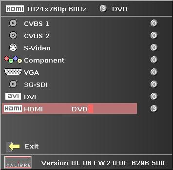
20 3.3. Main Menu The main menu lists the input channel select item, 6 sub menus, and a menu item for automatic setup of VGA modes. The 6 sub menus are Output, Colour, Geometry, PiP (HQView-500S) or Multiple Unit (HQView-510 and 520/530), Enhancement and System. On each menu page an Exit menu item is available to leave the menu or submenu. HQView-500S/510 and 520 also allow to leave (back up) a menu or submenu by pressing the up/down key simultaneously. HQView-530 has a separate back key for this purpose. Some adjustments are not applicable to all signal types or operating modes, in which case those nonapplicable functions will be ghosted (greyed out) and are not accessible. All menus have a top status line and a bottom firmware revision line. In the status line the currently selected input channel is indicated and the detected mode is identified. The bottom line shows the revision number of the boot loader behind BL, the revision number of the firmware behind FW and whether it is a 500S, 510, 520 or 530 type HQView unit. Navigating the menu system or changing values is done with the Menu/Enter and up / down keys in the case of HQView-500S, 510 and 520 or a Menu and Back keys together with a jog wheel/enter in the case of HQView-530. In the following sections the set-up method using the up and down keys is described. To set up your HQView-5xx it is recommended that you follow this procedure: 1/ Choose the correct output mode and parameters to suit your screen or projector. 2/ Select the correct input signal. 3/ Set the input levels and features appropriately to optimize the appearance of your image. 4/ Set any other parameters to suit your application. Note: The processor is designed to have separate memories for all the settings in each section. All Input parameters are specific to your chosen input channel and input signal type, they are not global to the unit. If you change the settings in for example the composite video channel you will not affect the settings you may have made in for example the DVI channel. All Output parameters only affect the output, they do not affect any of the inputs but please note that the appearance on the screen because it is the output these adjustments will appear to be global Input The list of available inputs can be scrolled through using the Up and Down keys or jog wheel. The new input is not selected until the Menu/Enter key is pressed. The list of inputs are: CVBS 1, CVBS 2, S- Video, Component, VGA, 3G-SDI, DVI, HDMI and Test Pattern. Test patterns can be generated by HQView-5xx without needing an input connected. When Test Pattern is selected as the input, the required test pattern can be chosen with the menu navigation up/down keys or jog wheel when the OSD menu is off or the LCD menu is in its default screen Output This menu contains adjustments associated with setting up outputs from the unit. The items are organized in three sub menus, Display Type, Gamma/Color/Crush and Output Config. Use the up and down keys or jog dial to scroll to the required item and press the Menu key. 16
21 Display Type Settings: LCD/Plasma, Projector The Display Type setting defaults to Projector or to the last set before power down. Select Projector if you drive a projector and need the warp function and edge blend capability. Set to LCD/Plasma if you do not need warp (including Location). Multiple unit configurations with auto zoom are available, but without edge blend. The real value of this mode is that the Flicker Filter becomes available. Note: For HQView-500S leave the setting to Projector mode, since there is no difference to LCD/Plasma mode Output Mode Settings: 640x480, 800x600, 1024x768, 1280x768, 1280x800, 1280x1024, 1360x768, 1366x768, 1400x1050, 1440x900, 1600x1200, 1680x1050, 1920x1200, 480i, 576i, 480p, 576p, 1080i, 720p, 1080p Set up the desired output resolution with output mode. The output mode setting should match the native resolution of the imaging device to avoid double scaling. The 3GSDI output does not feature the PC mode resolutions, This is because PC modes are not part of the international SDI standard. SDI supports only 480i/p, 576i/p, 720p and 1080i/p output modes. Available SDI output modes are indicated by an SDI connector/bnc symbol in the output mode selection list box of the OSD. SDI output modes not supported are indicated with this symbol crossed out red. The default output resolution as set by the factory or after a user issued factory reset is 640x480. Note:- If only a SDI capable monitor is connected no image is displayed and consequently the output resolution cannot by changes through the OSD. Pressing the Menu/Contrast up/contrast down key combination will switch the output resolution from 640x480 to 480i which SDI monitors should be capable to display. If a DVI or VGA monitor has issues to display this 480i mode, by pressing the key combination again the 640x480 output mode is set-up which all DVI and VGA monitors should be capable to display Location Settings: Front Tabletop, Front Ceiling, Rear Tabletop, Rear Ceiling The image can be flipped to accommodate different projection scenarios as well as screens mounted upside down Frame Rate Settings: 60 Hz, 50 Hz, 48 Hz, 24 Hz, Auto In auto mode the output frame rate follows the input frame rate as configured in the Output Config menu. Signals with 24Hz, 25Hz, 48Hz, 50Hz input modes get special treatment, Modes with other refresh rates are displayed at 60Hz. 24Hz input modes will be output at 24Hz if the output resolution is set to either 720p or 1080p and the Frame Rate setting in the Output Config menu includes 24Hz, otherwise it is displayed at twice the rate if the Frame Rate setting in the Output Config menu includes 48Hz. Otherwise a 24Hz input mode is displayed at 60Hz. 48Hz input modes will be output at 48Hz if the Frame Rate setting in the Output Config menu includes 48Hz. Otherwise it is displayed at 50Hz. 17
22 A 25Hz input mode is output at twice the frame rate 50Hz. An exception to the 24/25Hz input mode treatment is if the output resolution is set to 480i or 480p. 480i and 480p are always run at 60Hz output rate. 50Hz input modes are displayed at 50Hz output rate. The output frame rate can also manually set to 24Hz, 48Hz, 50Hz or 60Hz if possible, i.e. such output modes are available. Only 720p and 1080p output modes are available with 24Hz refresh rate. 480i and 480p output modes are only available at 60Hz refresh rate. For all other modes 48Hz, 50Hz and 60Hz refresh rate is available I/O Lock Available settings: Off, Source, Genlock, Auto If I/O Lock is switched off the output is run with a fixed refresh rate determined by the frame rate setting. This setting will result in the output vertical refresh rate deviating from the input refresh rate, even if both are nominally at the same rate. This causes occasional frame dropping or repeat. If I/O Lock is set to Source the output refresh rate is following the input video refresh rate if possible. If I/O Lock is set to Genlock the output refresh rate is following the vertical sync of an externally provided signal (GENLOCK BNC) if locking is possible. Locking is achieved by modulating the output clock and works if input and output refresh rate are nominally at the same rate, e.g. when frame rate is set to 60Hz and the video input is also 60Hz. If e.g. the video input rate is 50 Hz and the Frame rate is set to 60Hz, the output will enter free run mode. Note: When Frame Rate is set to Auto the matching frame rate is chosen. When I/O lock is set to Auto and a Genlock source is present to the GENLOCK BNC. The processor will lock with the external genlock signal if possible. If genlocking is not achievable, locking to the video source frame rate is tried. If that is not possible the output is running in free-run mode. The status line of the OSD window under Sync Mode indicates if the output signal is locked to the input signal (I/O Locked or Genlocked) or in free run mode (Free Run) Native Color Temp Settings: 5500, 6500, 7500, 9300, Native Colour Temp allows the user to select from pre-configured colour temperatures to match the display. If both Native Colour Temp set here in the Output menu and Colour Temp set in the Colour menu are set to the same value, no conversion is performed Output Gamma Settings: 1.0 to 3.0 in steps of 0.1 Output gamma allows to re-gamma video signals with pre-configured gamma values to match the display. Input gamma and output gamma both default to 2.2. If they are both set to the same value, there is no effect on the image. Note: If e.g. an adjustment to reduce the level of red in the image is required, select a higher number for the (input) Colour Temp in the Colour menu, or a lower number for the Native Colour Temp in the Output menu. 18
23 Output Config This Menu provides items to configure the output ports. Sync Mode The VGA output port can be operated with separate syncs, composite syncs and Sync-On-Green. Internally, the display interface processes data at a full ten bits per colour. Optimize for Display Settings: DVI forced, Optimized, DVI/HDMI Internally, the display interface processes data at a full ten bits per colour. A resolution of ten bits per colour is provided for the VGA output. The colour depth on the DVI-D output is determined by the supported standard of the attached monitor or device when set to DVI/HDMI. For DVI 1.0 and HDMI 1.1/1.2 devices it is 24 bit, for HDMI 1.3 compliant devices it is up to 36 bit. DVI forced will output with 24 bit colour depth irrespective of the supported standard of the attached monitor. When the Optimized setting is enabled the output resolution is automatically set to the native screen resolution of the attached display. The colour depth is determined in the same way as when set to DVI/HDMI. DVI Colour Space and DVI Range The colour space of the DVI output port can be set to RGB or YPbPr, the range can be set to Expand, Normal, Compress and Auto. A limited video range is only using the following greyscale for video information - 8 Bit System: 0x01.. 0xFE, 10 Bit System: 0x x03FB. Auto makes the best choice for the range for the DVI and 3G-SDI output. If the HDMI/DVI output does not behave as expected, e.g. because the HDMI display is not evaluating AVInfoFrames properly, the range can be changed manually. Frame Rates Settings: 60/50 Hz, 60/50/24 Hz, 60/50/48, 60/50/24/48 Limits the possible output frame rates that can be selected. It is primarily to be able to limit the choices available for the Auto refresh rate configuration discussed in paragraph G-SDI Data Map 720p and 1080i HD-SDI data can be output in YCbCr 4:2:2, YCbCr 4:4:4 or RGB 4:4:4 mode. 3GSDI data can be output as Level A or B data. 19
24 3.6. Colour This menu contains adjustments associated with setting up inputs to the unit. Use the Up and Down keys to scroll to the required item and press the Menu key or use the jog wheel Black-Level Offset Settings: 0 IRE, 7.5 IRE Used to select 7.5 IRE black level set-up adjustment. Used for NTSC type video signals. Should always be set to 7.5 IRE for HDMI video inputs and should usually be off for PAL type analog video inputs Black-Level Settings: -50 to 50 in steps of 1 Black level controls the offset applied to the video signal Contrast Settings: -50 to 50 in steps of 1 Contrast controls the gain applied to the video signal Saturation Settings: -50 to 50 in steps of 1 Control of video saturation, applies to all video inputs but not computer input signals or formats Hue Settings: -50 to 50 in steps of 1 Control of video hue, applies to all video inputs but not computer input signals or formats RGB values This is a user-defined colour temperature setting whereby individual R,G,B gain and RGB black level offset (bias) can be set so as to accurately calibrate a particular input to the display device Colour Temp Settings: 5500, 6500, 7500, 9300 Colour Temp allows the user to select from pre-configured color temperatures to match the colour temperature of the incoming signal. If both Colour Temp set here in the Colour menu and Native Colour Temp set in the Output menu are set to the same value, no conversion is performed Input Gamma Settings: Gamma 1.0, Gamma 1.5, Gamma 2.2, Gamma 2.8 Set this value to match the native gamma of the input signal. Input gamma and output gamma both default to 2.2. If they are both set to the same value, there is no effect on the image. 20
25 3.7. Geometry This menu contains adjustments associated with setting up position, aspect ratio and scale of the input signal. Scale can be as simple as an overscan up to arbitrarily warping the image Horizontal/Vertical Position Settings: in steps of 1 pixel/line Change the positional values to match the display boarders Edge Control Submenu for changing the position of the image edges, effectively scaling the image in horizontal and vertical direction. If Pan Tilt Zoom is activated Edge Control is disabled. It does effectively the same, but has greater range Warp Note: Warp is only available for HQView-510, 520 and 530. PC Warp is only available on HQView520 and 530 Details of the submenu for warping the image and defining projection condition. The projection condition can be Front Tabletop, Front Ceiling, Rear Tabletop or Rear Ceiling. The corresponding image flip is applied in addition to the following warp applications. The warp applications are Keystone, 4-Corner, Rotation, Portrait and PC. In the Keystone application the image can be adjusted to match a horizontally and vertically tilted screen. Also, Pin/Barrel distortion of the lens or screen can be adjusted simultaneously. Under the 4-Corner application all corners can be moved and the image linearity is calculated to fit into the given trapezoid. Please note that this function is designed to be used on Flat rectangular screens only. For more complex shapes please use the PC mode. The Rotation application rotates the image from -180 to 180 degree (one full circle) one degree at a time.. At the same time Pin/Barrel distortion of the lens or screen can be adjusted again. Special Portrait warp applications for clockwise (90 ) and counter-clockwise (270 ) rotation with scaling are provided. These functions cut out the centre of a normal landscape video signal, rotate it by 90 degrees and then scales that centre portion of the signal to fit a portrait mounted screen. Predefined warp maps for portrait mode act on a 16:9 input image. The area is rotated and scaled such that is fills a 9:16 screen. With PC application activated the HQView-520 and 530 communicate with the PC tool Warp Generator msi Warp Generator allows you to define an arbitrary screen in live operation by projecting a grid on the surface and move the grid points to get a rectangular output. This grid information can then be downloaded in one of eight slots used for real-time processing of image data which make the image appear rectangular on a curved screen. For convenience all settings can be reset with one button provided in the submenus Picture Format Settings: Standard, Full Screen, Crop, Anamorphic 21
26 Picture Format allows a user to select the displayed aspect ratio where the signal input is different to the display panel s natural aspect ratio. Note that some aspect ratios may not be applicable to all signal types, in which case selecting a nonapplicable aspect ratio conversion will have no effect on the displayed image. E.g. when a 16:9 image is displayed on a 16:9 panel all settings give an identical full screen image. Standard preserves the aspect ratio of the incoming image and scales the image to fit into the size of the panel. Dependant on the aspect ratio of the panel the image is either bordered by the right/left side or bottom/top of the panel. Non-used areas of the panel are displayed black (letterboxed). Full Screen scales the image to the size of the panel without preservation of the aspect ratio. Crop preserves the aspect ratio and scales the image to fit the screen. Dependant on the aspect ratio of the panel either the top/bottom or right/left areas of the image are cropped. Anamorphic scales the input image such that it is displayed with a 16:9 aspect ratio when displayed on the screen. The image is further scaled to fit into the size of the panel. Dependant on the aspect ratio of the panel the image is then either bordered by the right/left side or bottom/top of the panel. Non-used areas of the panel are displayed black (letterboxed) Overscan Settings: 0 to 10 in steps of 1 Overscan is used to slightly zoom into the image. Thus, the border area of an image is no longer displayed on the screen. This cuts off unwanted features at the top or bottom from e.g. head switching in legacy video images Pan Tilt Zoom This menu provided settings to zoom and shrink the image, as well as panning within the image. Pan Tilt Zoom (PTZ) can be switched on or off. When switched on the latency of the system is increased by one frame. Thus, there is a difference of a PTZ setting off or on with no zoom. PTZ settings can be saved per mode or globally, i.e. if applied globally the same PTZ settings are applied when switching input channels or changing the input mode. The Zoom slider allows to zoom into the image or shrink it. When Aspect Lock is set to On the separate slider for zooming vertically is greyed out and the horizontal zoom or shrink factor is used as vertical factor as well. The aspect ratio is preserved. When Aspect Lock is Off horizontal and vertical scaling factors can be chosen separately. With the Pan and Tilt sliders panning within the image in horizontal and vertical direction is possible. Off raster panning is allowed, i,e, the image can be shifted outside the active area of the display. For convenience the PTZ settings can be reset with one button. 22
27 3.8. PiP The HQView-500S has a PiP menu. It contains adjustments associated with setting up source, position and size of a picture in picture video image. HQView-510/520/530 have a Multiple Unit menu instead. However, HQView-510/520/530 can be rebooted as an HQView-500S through the menu system PiP Input Selects the video source for the PiP window. The available PiP video sources depend on the currently displayed (main) video source. If the main video source is HDMI, DVI, DVI-A, VGA or COMPONENT the available PiP sources are CVBS1, CVBS2, S-VIDEO and HD-SDI. If the main video source is CVBS1, CVBS2, S-VIDEO or HD-SDI the available PiP sources are HDMI, DVI, DVI-A, VGA and COMPONENT PiP Mode Settings: Off, PIP, PAP, POP Three picture in picture modes can be invoked. PIP displays a second channel within the main image. PAP displays both pictures side by side scaled to the vertical size of the panel. POP displays both images side by side preserving the aspect ratio of each source. The unused areas of the panel are displayed black. Note: PaP is not available with test pattern and also not available with PTZ activated. PoP has the same limitation and the output resolution needs to have greater or equal to 768 lines PiP Size Settings: Small, Medium, Large Note: Large is always available. Small and Medium are only available if the output resolution is greater or equal to 768 lines and the PiP mode has less than 1920 horizontal active pixels PiP Position Settings: Top Left, Top Right, Bottom Left, Bottom Right and Free H/V Selects the quadrant where to show the PiP image. When Free H/V is selected the horizontal and vertical PiP positioning sliders become available and the PiP can be moved over the screen. 23
28 3.9. Multiple Unit The HQView-510/520/530 have a Multiple Unit menu to set up each unit for use in a multi screen application. Multiple screens are stitched together to provide a bigger display with higher resolution than a single display. Each display is driven by a separate HQView unit. The processors in a multi screen system application can be used in two ways 1/ Auto zoom on:- processers cut out the specified section of the image and scale this section to fill the projected area. 2/ Auto zoom off:- processors do not cut the image, the correct portion of the image including overlapping blend region must be supplied to each processor independently. When using the Auto Zoom function explained below, each HQView unit gets the same graphics or video input signal through a distribution amplifier. The HQView unit cuts out and resizes the image to display the part of the image assigned to the corresponding screen. In a multi projection display the individual projections typically are chosen to overlap to give seamless transitions. Overlapping regions are illuminated by multiple projectors and are brighter than non-overlapping regions. These can be Soft Edge Blended for a uniform brightness over the total display the brightness in the overlapping regions has to be reduced electronically. PiP functionality is not supported due to higher bandwidth requirements of the video processing. Important: When using multiple HQView units to drive one single large screen, it is essential that all HQView units are I/O locked, otherwise motion tear will be observed at the boundaries of the image processed by each HQView unit. It is also essential that all HQView units are setup for the same processing latency (for example, either all units are in Best Picture mode or all units are in Low Latency mode) Auto Zoom Settings: On, Off Switches on the auto zoom resizing the video image to display the assigned part of the total image. The default is AutoZoom is off When Auto zoom is turned on the processor will cut and scale the portion of the picture selected by the matrix size and position selected described below Note The menu is scaled by the warp engine and may exceed the size of the screen. Also, only the active video area can be used for the on-screen menu. This would crop the menu and make it impossible to navigate. In this case auto zoom is deactivated and a message will indicate such situations. After changes are made to correct the situation AutoZoom can be reactivated Units Wide/Units High Settings: 1, 2, 3, 4/ 1, 2, 3, 4 for the maximum matrix size of 16 Provides the HQView unit information of the multi screen installation. The number of horizontally and vertically installed screens or projectors is entered. Note:- This function can be used in conjunction with the item below to select the blend regions to be provided even when auto zoom is turned off 24
29 Horizontal Pos/Vertical Pos Settings: 0 to 3 indicating co-ordinates 0,0, to 3.3 for the maximum matrix size of 16 With Auto zoom turned on this provides the HQView unit information of which window portion of the total image it is assigned to and has to process (cut out and resize). Note:- This function can be used in conjunction with the item above to select the blend regions to be provided even when auto zoom is turned off Blend Width The blend width menu provides sliders to set up the overlap region for left, right, top and bottom blend region. Note With the 5xx models when changing the slider value from within the OSD the blend area is not updated live immediately. An update is forced when pressing the menu/enter button, thus the slider is replaced by the menu. This is not ideal, but excessive blend area write time suggested this approach. The overlap is set up in output pixels with a range of up to one third of the output resolution. For a configuration with two projectors in horizontal direction the overlap can be higher to allow 16:9 images to fit on two combined projectors with an aspect ratio of 4:3 or 5:4. An offset for the blend region can be set-up as well. The region between the edge and the start of the blend area is black. The total pixels of blend area and offset region is limited by the same amount of pixels as for an offset of zero. Note: Each HQView unit needs to be provided with the exact same value for left and right blend region. Top and bottom blend region have to be identical as well, but don t need to have the same value as left and right. The HQView units do not communicate between each other and thus they have to make an assumption for auto zoom calculations and that is overlap of the neighbouring (and those beyond) projectors is identical Blend Curve Type The blend curve type menu sets the blending characteristics. For setting up the overlap the Align Pattern should be used. Align Patter reduces the image intensity of each pixel in the blend area by half. When the blend region set up through the blend width menu and the physical blend match the S-Curve characteristics can be switched on. The image intensity is gradually reduced from the start of the blend to the edge of the respective projector image. The S-Curve Value slider allows to control the steepness of the S-Curve. For convenience in this Blend Curve menu a duplicate of the Output Gamma slider can be found to match the grey scale of the images. When a custom alpha map was loaded into the file system of the unit it is recognized and the Custom Alpha Map menu item becomes available. Custom alpha maps can be uploaded through the web or remote control API interface of HQView. The map can be switched on and off. The map is combined with the Align or S-curve map internally generated Black-Level Uplift This enables the user to provide a black level uplift to compensate for the additional light leakage from multiple projectors in overlap regions. The black level uplift can be set for the 9 possible regions of the image. Setting the black level uplift for the middle of an edge also sets the black level uplift for the two adjacent corners, and if needed the corners can then be set individually. 25
30 The sliders for all regions which are not involved in edge blending for a given multiple unit configuration are greyed out, and the black level uplift for all these regions can be set together using the Non-Blend Region parameter Reduce Black-Level Uplift Width The Black Level Uplift field may need to be adjusted to achieve a perfect result. There may be an area of light leakage beyond the edge of the active image from the projector. With these controls the edges of the black uplift region can be moved so they can be aligned with the edges of the area of light leakage. In the case of projection under non-rectangular conditions the projection fields of adjacent projectors are not aligned with the blend region. The corners of the non-blend region can be moved to allow tracking of the edge of the projection field of adjacent projectors Enhancement The enhancement menu provides image enhancement functions. Note that the enhancement settings apply to video input signals only, not computer graphics signals Sharpness Settings: -50 to 50 in steps of 1 These are peaking filters to improve high- Control of the sharpening enhancement filters' levels. frequency response. Note that setting this control too high on a signal which already has good high frequency response will cause ringing or ghosting Detail Settings: 0, 1, 2, 3 This filter provides powerful 2D image enhancement which can be used to greatly improve detail definition and clarity without causing image ringing or ghosting. It improves both horizontal and vertical detail. Correct setting of the detail enhance filter can make SD signals look virtually indistinguishable from true HD. At setting 0 the filter is switched off, with setting 3 providing the highest effect Video Filters The video filters menu provides LTI/CTI filters, TRNR/MNR noise reduction filters and a CCS cross color suppression filter. The LTI filter enhances the sharpness of the luminance component. The CTI filter enhances the color sharpness of the chrominance signal by increasing the steepness of color edges. TRNR (Temporal Recursive Noise Reduction) and MNR (Mosquito Noise Reduction) are available for SD input signals only. These filters reduce spatial and temporal noise as well as block artifacts. CCS is a filter to reduce luminance to chrominance cross talk of composite video signals (only) which appears as a coarse rainbow pattern or random colors in regions of fine details Flicker Filter By default the filters are off. 26
31 The Flicker Filter reduces interlace horizontal line edge bounce or flicker when scan converting from a computer progressive input format to an interlaced output signal. By choosing the filter strength and recursion mode it is possible to choose between higher levels of flicker reduction or better motion reproduction. The Flicker Filter when turned on is applied to the computer input ports DVI and HDMI. It is not applied to inputs which are video (Composite, S-Video, Component and 3G-SDI) or to interlaced modes on DVI and HDMI. Filter Strength controls the filter weighting of prior field versus current field. Recursion chooses between vertical filtering of current and prior input fields, or current field and recursive data output from filter during prior field System This Menu selection contains functions which are more applicable to system operation than to picture adjustment User Settings: USER 1, 2, 3, 4 Pre-defined settings stored under a user name can be selected. Users can store their preferred HQView-5xx settings and recall these profiles by picking up their user name from this menu. Note: Using the Web interface, (any number of) settings can also be stored/restored to/from a PC disc drive Names/Profiles The Names/Profiles menu provides input masks to rename the generic input channels and user names. User names and input channel names can be changed to any word with a maximum of 12 alpha numeric characters with a value range of 0-9, A-Z and blank. The Names/Profiles menu allows the user to store profiles under a certain user name. It also allows to copy user profiles by loading a profile stored under one user name and save it under another user name. Reset Profile allows to restore default HQView-5xx settings for the currently selected user Input Config Inputs can be configured through the following sub-menus: VGA Setup: Submenu for adjusting analogue computer video. A button for automatic setup of frequency and phase of the sampling clock is provided. This automatic adjustment is strongly recommended. Frequency (Clock) and phase can also be altered manually. DVI/HDMI Setup: The DVI-I connector will accept either DVI-D or VGA analogue inputs. The DVI-I channel can be configured for either. The equalisation of the DVI interface can be boosted to allow for extended cable length. 27
32 The automatic HDMI and DVI Color Space and Range settings can be overwritten in this menu. Range can be set to limited video mode or full range. The color space can be set to RGB or YCbCr. The DDC can be taken off line. When setting HDCP Input to off HQView pretends to be non HDCP compliant forcing the source to not encrypt data which is not copy protected. 28
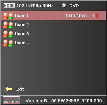
33 SDI Setup: For 3GSDI Level A or B type input modes can be chosen. SDI audio input is routed to the HDMI and 3GSDI output connector by default. HQView-5xx can also be set to monitor audio on the SPDIF connector. Audio on the HDMI/3GSDI connector and SPDIF connector are mutually exclusive. Two consecutive SDI audio channels can be output on the HDMI/3GSDI output interface. The group can be chosen. Or all eight SDI audio channels can be transmitted. Component Setup: The component interface of the HQView-5xx is configured through this submenu. The Colour Space can be set to YPbPr or RGB. The sync signal can be stripped from the Green or Y channel with the setting 3 Wire or from the separate sync line with the setting 4 Wire. The Auto setting will automatically detect a sync signal and set-up the HQView-5xx accordingly. This is setup in under Synchronisation. Test Pattern: When the OSD menu is off the test pattern can be toggled through by pressing the up or down keys of the keypad. For unit control through a web browser or to set up a certain default test pattern please use the input configuration menu. Custom test patterns loaded into the file system of the unit through the web interface, can be accessed through the same means. Instead of custom test patterns also a screen grab of the current video can be stored in one of the four slots provided for custom test patterns. The speed of the moving cross test pattern can be changed. Also, the foreground and background colour and the line width of the moving cross test pattern can be changed in this menu. Note: Most test patterns are scaled in multiple unit configurations with Autozoom enabled since they are useful for setting up the blend and warp of the system. The SMPTE, and Pluge Patterns are not scaled. Switching Transition: When switching input channels by default the last frame of the prior displayed image is frozen and displayed until a stable image of the new input channel can be shown. The switchover process is supposed to be as seamless as possible. The source and monitor add switching noise due to unforeseeable activity of the firmware in said devices. By default HQView is in auto frame rate switching and I/O lock mode. In order to get a best smooth switching result with the source and monitor I/O lock and auto frame rate switching have to be switched off in the Output/Display Type menu. The switching transition of HQView can be set to Freeze, Blank, Fast Fade and Slow Fade. Freeze halts the prior channel image until the new channel image is stable. Blank switches the output to show a black screen instead of the last channel image. Fast and slow fade have the prior channel image faded out and fade into the new channel video image once it is stable Display Mode The Display Mode can be set to either Low Latency or Best Picture. In Best Picture optimum image processing is applied, whereas in Low Latency mode the lowest latency is achieved. 29
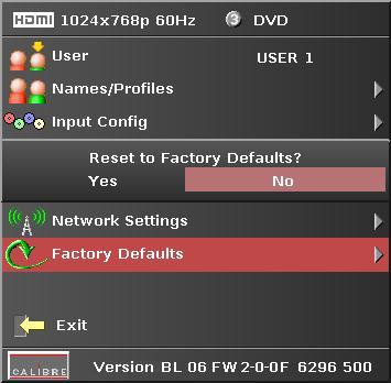
34 The flicker of interlaced video is not suppressed totally for the latter setting. It has the disadvantage of conventional CRT TVs, but also their advantage of almost no delay in response, which is important for applications such as gaming, simulation or imaging in medical treatment. The latency of the system is ¼ of a frame for progressive input and progressive output when I/O locked. If the output is free running the latency is oscillating between ¼ of a frame and 1 frame. Switching on PTZ adds one frame of latency. Switching on warp adds another frame of latency. If an interlaced video signal is processed in Best Picture mode, this will add one more field of latency. In Low Latency mode this extra field of latency is avoided Menu Settings This menu provides items to change the menu position and menu display time, i.e. the time after which the OSD is switched off again with no user interaction. OSD Messages can be activated and deactivated. The menu language can be altered and the keypad can be locked. To unlock the keypad a combination of keys has to be pressed at the same time. The locking of the keyboard is accompanied by the message (HQView-500S/510/520): Keypad is locked. Press Menu/Up/Down to unlock. When successfully unlocking the keypad the message shows up: Keypad unlocked. HQView-530 has an additional menu item to switch on/off the OSD menu. The LCD menu which is a copy of the OSD menu then serves as the only menu navigation monitoring device Network Settings The factory default is DHCP. The Network Settings menu allows to configure the HQView-5xx TCP/IP address. Under Address Type a static or DHCP leased address can be chosen. The static address and Netmask needs to be entered manually. The Network Settings menu has a section with information on the DHCP Status and IP address assigned to the board, as well as the fixed MAC Address programmed into the HQView-5xx. The DHCP status is Off when static assignment is used or it displays an address when DHCP has leased an address accordingly or it is None assigned if the lease was not successful. Note: When changing from DHCP to Static mode or vice versa it is strongly recommended that HQView-5xx is powered down after such a change, then powered back up, so that it is properly recognised by other devices on the network Factory Defaults This button lets you restore all settings to the default values of the HQView-5xx, this, provide a means to get back to a known (good) system state. A request will come up and ask to confirm prior to actual restore Operation Mode This menu item is only available on a HQView-510/520/530. It allows to choose between the regular multiple unit mode with blend and warp and a PiP mode. Selecting the PiP mode will effectively boot the HQView-510/520/530 to emulate a HQView-500S. A HQView-500S has PiP/PaP/PoP capability but no edge blend. The Operation Mode can be switched back to Multiple Unit. 30

35 4.1. Introduction REMOTE CONTROL WEB SERVER HQView-5xx features a web server which connects to a PC web browser via TCP/IP. The menu system of HQView-5xx is mirrored into the web browser and all menu items can be accessed and controlled through the keyboard or mouse of the PC Installing the Software No extra software needs to be installed on a PC. The PC web browser is used as the graphical user interface for all control items. To connect to the HQView-5xx the TCP/IP address of the unit has to be entered into the address list box of the web browser in the following format The TCP/IP address assigned to HQView-5xx can be found in the System/Network Settings menu Discovery Tool Calibre provides a DiscoveryTool.exe Windows application to identify Calibre boxes in the network. Clicking on the link of the recognized box will open a browser and make a connection to the corresponding box. The box identifier is made up of PV6S in the case of HQView-5xx followed by the 6 least significant digits of the MAC address. The MAC address of the box can be found in the System/Network Settings menu. Note: This is for use on a network not on a single wire connection. 31
LEDView510 and LEDView530 Operating Instructions
 LEDView510 and LEDView530 Operating Instructions Version 2.20 IMPORTANT NOTICE: When using extreme shrink to drive a single or few LED modules the OSD menu of LEDView may become hardly readable - including
HQView-325 Operating Instructions
 HQView-325 Operating Instructions This manual explains how to operate your HQView-325 image scaler. HQView-325 is designed to provide users with a powerful and flexible method of driving large display
OPERATING GUIDE. HIGHlite 660 series. High Brightness Digital Video Projector 16:9 widescreen display. Rev A June A
 OPERATING GUIDE HIGHlite 660 series High Brightness Digital Video Projector 16:9 widescreen display 111-9714A Digital Projection HIGHlite 660 series CONTENTS Operating Guide CONTENTS About this Guide...
USER MANUAL MODEL: VP-793 Warp-Blend
 KRAMER ELECTRONICS LTD. USER MANUAL MODEL: VP-793 Warp-Blend VP-793 Operating Instructions Version K1.3 This manual explains how to operate your VP-793 warp-blend scaler. VP-793 is designed to provide
USER MANUAL MODEL: VP-792 Warp and Blend Scaler
 KRAMER ELECTRONICS LTD. USER MANUAL MODEL: VP-792 Warp and Blend Scaler VP-792 Operating Instructions Version K 1.4 This manual explains how to operate your VP-792 warp and blend scaler. VP-792 is designed
G-106Ex Single channel edge blending Processor. G-106Ex is multiple purpose video processor with warp, de-warp, video wall control, format
 G-106Ex Single channel edge blending Processor G-106Ex is multiple purpose video processor with warp, de-warp, video wall control, format conversion, scaler switcher, PIP/POP, 3D format conversion, image
LEDView530 Operating Instructions
 LEDView530 Operating Instructions Version 2.46 IMPORTANT NOTICE: When using extreme shrink to drive a single or few LED modules the OSD menu of LEDView may become hardly readable - including the assigned
G-106 GWarp Processor. G-106 is multiple purpose video processor with warp, de-warp, video wall control, format conversion,
 G-106 GWarp Processor G-106 is multiple purpose video processor with warp, de-warp, video wall control, format conversion, scaler switcher, PIP/POP, 3D format conversion, image cropping and flip/rotation.
PremierViewProHD-LED Operating Instructions
 PremierViewProHD-LED Operating Instructions This manual explains how to operate your PremierViewProHD-LED (PVProHD-LED) image scaler. The PVProHD-LED is designed to provide users with a powerful and flexible
4K Presentation switcher-scaler Chameleon PS200/300 series 2017
 4K Presentation switcher-scaler Chameleon PS200/300 series 2017 Chameleon PS200/300 series HQUltra technology was chosen by the European Broadcast Union for frame rate and standards conversion of the recent
The absolute opposite of ordinary. G804 Quad Channel Edge Blending processor
 The absolute opposite of ordinary G804 Quad Channel Edge Blending processor Input: up to 4096*2160 @60hz 4:4:4 full color sampling Output: 2048*1080 @60Hz New generation Warp & Edge blending engine Technical
OPERATING GUIDE. M-Vision Cine 3D series. High Brightness Digital Video Projector 16:9 widescreen display. Rev A August A
 OPERATING GUIDE M-Vision Cine 3D series High Brightness Digital Video Projector 16:9 widescreen display 112-022A Digital Projection M-Vision Cine 3D series CONTENTS Operating Guide CONTENTS About this
SIERRA VIDEO SP-14 SETUP GUIDE. User s Manual
 SIERRA VIDEO SP-14 SETUP GUIDE User s Manual SP-14 Setup Guide Version S 1.0 1 Contents Introduction 3 The Basic System 4 Flexible Connectivity 5 Control via Front Panel Buttons 6 Set Scaler Functions
G-700LITELite multiple Channel warping processor
 G-700LITELite multiple Channel warping processor Version: 2.01, Date: 2017-07 G-700Lite is a warping processor with the ability to provide multiple processing modules to control from 1 to 4 projectors
DVI/PC/HD to DVI/PC Scaler - ID# 15320
 DVI/PC/HD to DVI/PC Scaler - ID# 15320 Operation Manual Introduction This DVI/PC/HD to DVI/PC Scaler is capable of scaling and sourceswitching from PC (VGA), Component Video (SD/HD) and DVI input signals
CP-255ID Multi-Format to DVI Scaler
 CP-255ID Multi-Format to DVI Scaler Operation Manual DISCLAIMERS The information in this manual has been carefully checked and is believed to be accurate. Cypress Technology assumes no responsibility
User Manual. PC / HD Scaler. with advanced video processing. VGA to Component Video Component Video to VGA VGA to VGA Component to Component
 User Manual PC / HD Scaler with advanced video processing VGA to Component Video Component Video to VGA VGA to VGA Component to Component Model 1366 WARNINGS Read these instructions before installing or
DVI Digital scaler with ultra high bandwidth ID#442
 DVI Digital scaler with ultra high bandwidth ID#442 Operation Manual Introduction Congratulations on your purchase of the DVI Digital scaler with ultra high bandwidth. Please read this to become familiar
USER MANUAL. HIGHlite Laser 3D Series INSTALLATION AND QUICK-START GUIDE CONNECTION GUIDE OPERATING GUIDE REMOTE COMMUNICATIONS GUIDE REFERENCE GUIDE
 HIGHlite Laser 3D Series High Brightness Digital Video Projector USER MANUAL INSTALLATION AND QUICK-START GUIDE CONNECTION GUIDE OPERATING GUIDE REMOTE COMMUNICATIONS GUIDE REFERENCE GUIDE 114-913A Digital
HIGHlite Laser 3D Series High Brightness Digital Video Projector
 HIGHlite Laser 3D Series High Brightness Digital Video Projector 4INSTALLATION AND QUICK-START GUIDE 4CONNECTION GUIDE 4OPERATING GUIDE 4REFERENCE GUIDE 114-913C About This Document Follow the instructions
G406 application note for projector
 G406 application note for projector Do you have trouble in using projector internal warp and edge blending function? Inconvenient in multiple signal source connection System resolution is not enough after
User Manual. Model 1365 Video Scaler
 User Manual Model 1365 Video Scaler Model 1365 PC/HD Video Converter Table Of Contents 1.0 Introduction........................3 2.0 Specifications....................... 4 3.0 Checking Package Contents................5
USER MANUAL. HIGHlite Laser 3D Series INSTALLATION AND QUICK-START GUIDE CONNECTION GUIDE OPERATING GUIDE REFERENCE GUIDE
 HIGHlite Laser 3D Series High Brightness Digital Video Projector USER MANUAL INSTALLATION AND QUICK-START GUIDE CONNECTION GUIDE OPERATING GUIDE REFERENCE GUIDE 114-913B Digital Projection HIGHlite Laser
SUPERSCALE Multi-Format to HDMI Scaler
 SUPERSCALE Multi-Format to HDMI Scaler Operation Manual DISCLAIMERS The information in this manual has been carefully checked and is believed to be accurate. SPATZ assumes no responsibility for any infringements
CORIO master C3-540 Series
 Key Features Manage up to 4 independent video walls Uses CORIOgrapher; simple, powerful software interface Universal DVI Inputs/Outputs: (HDMI/CV/YC/RGB/YPbPr) SDI Inputs/Outputs: SD/HD-SDI/3G-SDI to 1080p60
HDMI Digital scaler with ultra high bandwidth ID#443
 HDMI Digital scaler with ultra high bandwidth ID#443 Operation Manual Introduction Congratulations on your purchase of the HDMI Digital scaler with ultra high bandwidth. The HDMI Digital scaler with ultra
. ImagePRO. ImagePRO-SDI. ImagePRO-HD. ImagePRO TM. Multi-format image processor line
 ImagePRO TM. ImagePRO. ImagePRO-SDI. ImagePRO-HD The Folsom ImagePRO TM is a powerful all-in-one signal processor that accepts a wide range of video input signals and process them into a number of different
CSLUX-300 Multi-Format to HDMI Scaler
 CSLUX-300 Multi-Format to HDMI Scaler Operation Manual DISCLAIMERS The information in this manual has been carefully checked and is believed to be accurate. Cypress Technology assumes no responsibility
YCbCr (480i/576i) and RGBsync. 4 Press Component to change source to component connec tor. This connector supports YPbPr (480p/576p/720p/1080i)
 and RGBsync. 4 Press Component to change source to component connec tor. This connector supports YPbPr (480p/576p/720p/1080i)") Introduction Product Features This product is an XGA single chip 0.7 DLP TM projector. Outstanding features include: u True XGA, 1024 x 768 addressable pixels u Single chip DLP TM technology u NTSC3.58/NTSC4.43/PAL/SECAM
Introduction Product Features This product is an XGA single chip 0.7 DLP TM projector. Outstanding features include: u True XGA, 1024 x 768 addressable pixels u Single chip DLP TM technology u NTSC3.58/NTSC4.43/PAL/SECAM
USER MANUAL. VP-435 Component / UXGA HDMI Scaler MODEL: P/N: Rev 13
 KRAMER ELECTRONICS LTD. USER MANUAL MODEL: VP-435 Component / UXGA HDMI Scaler P/N: 2900-000262 Rev 13 Contents 1 Introduction 1 2 Getting Started 2 2.1 Achieving the Best Performance 2 2.2 Safety Instructions
HIGHlite 660 3D Series High Brightness Digital Video Projector
 HIGHlite 660 3D Series High Brightness Digital Video Projector 4INSTALLATION AND QUICK-START GUIDE 4CONNECTION GUIDE 4OPERATING GUIDE 4REFERENCE GUIDE 114-242E About This Document Follow the instructions
KRAMER ELECTRONICS LTD. USER MANUAL
 KRAMER ELECTRONICS LTD. USER MANUAL MODEL: Projection Curved Screen Blend Guide How to blend projection images on a curved screen using the Warp Generator version K-1.4 Introduction The guide describes
VP-796(A)(ASV) / VP-797A(ASV) / VP-798ASV. User s Manual
(ASV) / VP-797A(ASV) / VP-798ASV. User s Manual") VP-796(A)(ASV) / VP-797A(ASV) / VP-798ASV User s Manual COPYRIGHT This document and the software described within it are copyrighted with all rights reserved. Under copyright laws, neither the documentation
VP-796(A)(ASV) / VP-797A(ASV) / VP-798ASV User s Manual COPYRIGHT This document and the software described within it are copyrighted with all rights reserved. Under copyright laws, neither the documentation
CSLUX-300I Multi-Format to HDMI Scaler
 CSLUX-300I Multi-Format to HDMI Scaler Operation Manual DISCLAIMERS The information in this manual has been carefully checked and is believed to be accurate. Cypress Technology assumes no responsibility
CORIO master C3-540 Series CORIO 3 Technology
 C3-540 CORIO master offers a new, more efficient approach to building video systems. Using TV One s Remotely latest CORIO controlled 3 technology, version it gives the user access to new levels of video
Compass 3.0 Presentation Switcher Manual
 Manual Based on firmware revision xx 3477.bin Release Date 11/10/2016 43234 LIT1605 COPYRIGHT This document and the software described within it are copyrighted with all rights reserved. Under copyright
CP-255ID CV, SV, VGA and DVI to DVI Scaler / Converter OPERATION MANUAL
 CP-255ID CV, SV, VGA and DVI to DVI Scaler / Converter OPERATION MANUAL DISCLAIMERS The information in this manual has been carefully checked and is believed to be accurate. CYP (UK) Ltd assumes no responsibility
C / C / C Scaling with Speed and Agility
 C2-2855 / / Scaling with Speed and Agility A new generation of Scalers tvone s evolutionary development of our renowned CORIO 2 scaler technology continues to provide commercial integrators with unsurpassed
CSLUX-300I Multi-Format to HDMI Scaler
 CSLUX-300I Multi-Format to HDMI Scaler Operation Manual SAFETY PRECAUTIONS Please read all instructions before attempting to unpack, install or operate this equipment and before connecting the power supply.
Video Scaler Pro with RS-232
 Video Scaler Pro with RS-232 - ID# 783 Operation Manual Introduction Features The Video Scaler Pro with RS-232 is designed to convert Composite S-Video and YCbCr signals to a variety of computer and HDTV
HD Mate Scaler USER MANUAL.
 HD Mate Scaler USER MANUAL www.gefen.com ASKING FOR ASSISTANCE Technical Support: Telephone (818) 772-9100 (800) 545-6900 Fax (818) 772-9120 Technical Support Hours: 8:00 AM to 5:00 PM Monday through Friday
CYPRESS TECHNOLOGY CO., LTD.
 (1). Introduction Congratulations on your purchase of the Cypress Video Scaler CSC-200P. Our professional Video Scaler products have been serving the industry for many years. In addition to Video Scalers,
Instruction Guide. Component/Composite/S-Video to DVI-D/HDTV Scaler and Converter Component/Composite/S-Video to VGA/HDTV Scaler and Converter
 VIDEO SCALER Component/Composite/S-Video to DVI-D/HDTV Scaler and Converter Component/Composite/S-Video to VGA/HDTV Scaler and Converter VID2DVIDTV (DVI) VID2VGATV (VGA) Instruction Guide * Actual product
ivw-fd122 Video Wall Controller MODEL: ivw-fd122 Video Wall Controller Supports 2 x 2 Video Wall Array User Manual Page i Rev. 1.
 MODEL: ivw-fd122 Video Wall Controller Supports 2 x 2 Video Wall Array User Manual Rev. 1.01 Page i Copyright COPYRIGHT NOTICE The information in this document is subject to change without prior notice
PS200 PS200T PS300T 4K Scalers-Switchers. User s Manual
 PS200 PS200T PS300T 4K Scalers-Switchers User s Manual This page is intentionally left blank 2 COPYRIGHT This document and the software described within it are copyrighted with all rights reserved. Under
Instruction Manual 1T-AVPC-HDMI HDMI Video Scaler
 99 Washington Street Melrose, MA 02176 Phone 781-665-1400 Toll Free 1-800-517-8431 Visit us at www.testequipmentdepot.com Instruction Manual 1T-AVPC-HDMI HDMI Video Scaler Table of Contents 1.0 Introduction
USER MANUAL. VP-501N UXGA Scan Converter MODEL: P/N: Rev 5
 KRAMER ELECTRONICS LTD. USER MANUAL MODEL: VP-501N UXGA Scan Converter P/N: 2900-300183 Rev 5 Contents 1 Introduction 1 2 Getting Started 2 2.1 Achieving the Best Performance 2 2.2 Safety Instructions
2D/3D Multi-Projector Stacking Processor. User Manual AF5D-21
 2D/3D Multi-Projector Stacking Processor User Manual AF5D-21 Thank you for choosing AF5D-21 passive 3D processor. AF5D-21 is an advanced dual channel passive 3D processor with 10 bits high end scaler and
HIGHlite 740 Series High Brightness Digital Video Projector
 HIGHlite 740 Series High Brightness Digital Video Projector 4INSTALLATION AND QUICK-START GUIDE 4CONNECTION GUIDE 4OPERATING GUIDE 4REFERENCE GUIDE 114-751I About This Document Please follow the instructions
CONTENT Product Introduction... 2 Packing Configuration...3 Hardware Orientation... 4 Front Panel... 4 Back Panel... 6 Using Your Product... 7 Content
 VENUS X1PRO Quick Start 4K input support in DP, HDMI and DVI Input standard 2K formats Scale and switch seamlessly between 2K and 4K inputs Output to any format 2K or 4K EDID management on board HDCP 2.0
PC/HDTV 2-Way Converter
 Vision for Net Media HDView PC/HDTV 2-Way Converter Operation Manual 1. Introduction The HDView is a high-performance universal PC/HDTV to PC/HDTV converter. It combines the functions of a video scaler,
HD Leeza. Quick Setup Guide
 Page 1 of 15 Model KD-HD1080P Key Digital Video Processor Quick Setup Guide Have a question or a technical issue with your set-up? Call the Key Digital Hotline at: 866-439-8988 or 203-798-7187 E-mail the
User Manual rev: Made in Taiwan
 CV-500S HDMI to Component/CVBS & Audio Scaler Converter User Manual rev: 131218 Made in Taiwan The CV-500S HDMI to Component/CVBS & Audio Scaler Converter has been tested for conformance to safety regulations
High-Definition Scaler. GTV-HIDEFS. User Manual
 High-Definition Scaler GTV-HIDEFS User Manual www.gefentv.com Technical Support: Telephone (818) 772-9100 (800) 545-6900 Fax (818) 772-9120 Technical Support Hours: 8:00 AM to 5:00 PM Monday thru Friday.
SX7. Saga 7" Super Bright HDMI/3G-SDI Field Monitor with 3D-LUTs. Quick Start Guide. What s Included CHECKED BY
 SX7 Quick Start Guide Saga 7" Super Bright HDMI/3G-SDI Field Monitor with 3D-LUTs What s Included 1 x Saga X7 Monitor 1 x V-Mount Plate (Attached) 1 x Mini-XLR to P-TAP Cable 1 x Dual Sony L Battery Adapter
PRO-ScalerHD2V HDMI to VGA & Audio Scaler Converter. User s Guide. Made in Taiwan
 PRO-ScalerHD2V HDMI to VGA & Audio Scaler Converter User s Guide Made in Taiwan Congratulations for owning a gofanco product. Our products aim to meet all your connectivity needs wherever you go. Have
ESI VLS-2000 Video Line Scaler
 ESI VLS-2000 Video Line Scaler Operating Manual Version 1.2 October 3, 2003 ESI VLS-2000 Video Line Scaler Operating Manual Page 1 TABLE OF CONTENTS 1. INTRODUCTION...4 2. INSTALLATION AND SETUP...5 2.1.Connections...5
Video Converter & Scaler
 Video Converter & Scaler VGA or Composite Video to DVI-I Output Converter and Scaler VGA2DVII Instruction Manual Actual product may vary from photo FCC Compliance Statement This equipment has been tested
Powerful blending and warping simplified
 www.optoma.co.uk HQView320/325/520/530 Projector edge blending and image warping Powerful blending and warping simplified The Optoma blending products, powered by industry leading technology from Calibre
C / C / C Scaling with Speed and Agility
 / / Scaling with Speed and Agility A new generation of Scalers tvone s evolutionary development of our renowned CORIO 2 scaler technology continues to provide commercial integrators with unsurpassed image
VSP 198CVS Quick Start
 VIEWSIZE THE WORLD VSP 198CVS Quick Start Max 2048 1152@60Hz/2560 1152 50Hz input/output resolution User customize output resolution 3G/HD/SD-SDI input Multiple cascade mapping for super resolution DVI
SC-HD-2A HDMI Scaler & Audio Embedder / Extractor
 User s Manual SC-HD-2A HDMI Scaler & Audio Embedder / Extractor Scale HDMI or DVI video Embed Digital or Analog Audio into HDMI output Extract (De-embed) Digital and Analog Audio from HDMI input UMA1246
USER MANUAL. VP-426 HDMI-PC Scaler MODEL: P/N: Rev 4.
 USER MANUAL MODEL: VP-426 HDMI-PC Scaler P/N: 2900-300277 Rev 4 www.kramerav.com Contents 1 Introduction 1 2 Getting Started 2 2.1 Achieving the Best Performance 2 2.2 Safety Instructions 2 2.3 Recycling
AX20. Atlas 19.5" 3G-SDI/HDMI Field and Studio Monitor with 3D LUTs & Scopes. Quick Start Guide. What s Included CHECKED BY
 AX20 Quick Start Guide Atlas 19.5" 3G-SDI/HDMI Field and Studio Monitor with 3D LUTs & Scopes What s Included 1 x Atlas 19.5" Monitor 1 x AC Adapter 1 x Sunhood CHECKED BY AX20 FRONT 1920 x 1080 19.5 inch
MDS 100 LINE MULTIPLIER, SCAN CONVERTER AND SWITCHER
 5 INPUTS WITH ASSOCIATED AUDIO 2 SIMULTANEOUS CONVERSIONS: PC/TV AND TV/PC WIDE RANGE OF CORRECTIONS AND ADJUSTMENTS MUTE AUDIO FUNCTION ON BOTH OUTPUTS OSD ON BOTH OUTPUTS MAINTENANCE OF PRESETTINGS POSSIBILITY
2-Channel Video Processor Models C2-7260, C2-7210, C2-7200
 C2-7260 2-Channel 17-Input Video Processor moves well beyond video processing, switching and HD-SDI Up, Down and Cross Convers ion by providing many additional features. Two independent video processing
VSP 516S Quick Start
 VIEWSIZE THE WORLD VSP 516S Quick Start Max 2048 1152@60Hz/2560 816 60Hz input/output resolution User customize output resolution 3G/HD/SD-SDI input Multiple cascade mapping for super resolution Seamless
17 19 PROFESSIONAL LCD COLOUR MONITOR ART
 17 19 PROFESSIONAL LCD COLOUR MONITOR ART. 41657-41659 Via Don Arrigoni, 5 24020 Rovetta S. Lorenzo (Bergamo) http://www.comelit.eu e-mail:export.department@comelit.it WARNING: TO REDUCE THE RISK OF FIRE
CSO-T2. Instant HQV HD Scaler Box. Operation Manual CSO-T2
 CSO-T2 Instant HQV HD Scaler Box Operation Manual CSO-T2 1 Disclaimers The information in this manual has been carefully checked and is believed to be accurate. Cypress Technology assumes no responsibility
Click to Print This Page. 9,500 ANSI / 10,500 ISO Lumens Contrast Ratio: 10,000:1 (Dynamic Black) 1,000:1 native Part Number:
 1,000:1 native Part Number:") Digital Projection Projector Specification Click to Print This Page Specification Sheet E-Vision Laser 0K 9,500 ANSI / 0,500 ISO Lumens Contrast Ratio: 0,000: (Dynamic Black),000: native Part Number: 8-060
Digital Projection Projector Specification Click to Print This Page Specification Sheet E-Vision Laser 0K 9,500 ANSI / 0,500 ISO Lumens Contrast Ratio: 0,000: (Dynamic Black),000: native Part Number: 8-060
User Guide. Video to VGA/HD Converter/Scaler DVI-3420a. Video to DVI Converter/Scaler DVI-3410a
 User Guide Video to VGA/HD Converter/Scaler DVI-3420a Video to DVI Converter/Scaler DVI-3410a TABLE OF CONTENTS SECTION PAGE PRODUCT SAFETY... 1 PRODUCT LIABILITY.... 1 1.0 INTRODUCTION.... 2 2.0 SPECIFICATIONS....
TFT LCD MONITOR USER MANUAL. L80AP and L101AP
 TFT LCD MONITOR USER MANUAL L80AP - 8.0 and L101AP - 10.1 Table Of Contents Table of contents/ Warning.... 2 Precautions...3 About this user manual and products / Items included in the delivery..... 4
PRO-3GSDIHDMI. 3G-SDI Extender with HDMI Scaler OPERATION MANUAL
 PRO-3GSDIHDMI 3G-SDI Extender with HDMI Scaler OPERATION MANUAL Safety Precautions Please read all instructions before attempting to unpack or install or operate this equipment, and before connecting the
G3 NET 2K USER MANUAL
 G3 NET 2K USER MANUAL Article No: RGB-RD-UM-G3 NET 2K E001 Revision No: V1.0 CONTENTS CONTENTS... 1 Declarations... 3 FCC/Warranty... 3 Operators Safety Summary... 4 Installation Safety Summary... 4 Chapter
SC-1080D. Multi-format PC/HD Video Scaler
 SC-1080D Multi-format PC/HD Video Scaler SUPPORT & ORDERING INFORMATION For technical support, Call 714-641-6607 or fax 714-641-6698 Order by phone: toll-free in the U.S. 800-959-6439 Web site: www.hallresearch.com
PC/HDTV to PC/HDTV converter (CP-251F)
") PC/HDTV to PC/HDTV converter (CP-251F) Operation Manual This Converter has been especially modified to also accept RGsB Sync on Green Operation Controls and Functions Front Panel 1. Reset/ and +- The and
PC/HDTV to PC/HDTV converter (CP-251F) Operation Manual This Converter has been especially modified to also accept RGsB Sync on Green Operation Controls and Functions Front Panel 1. Reset/ and +- The and
PRODUCT FLYER. Maybachstrasse 10 D Karlsruhe
 2B PRODUCT FLYER 2B Multi Media Interface Board for TFT and Plasma Displays The products and specifications are subject to change without notice. Please ask for the latest releases to guarantee the satisfaction
Display-Shoot M642HD Plasma 42HD. Re:source. DVS-5 Module. Dominating Entertainment. Revox of Switzerland. E 2.00
 of Display-Shoot M642HD Plasma 42HD DVS-5 Module Dominating Entertainment. Revox of Switzerland. E 2.00 Contents DVS Module Installation DSV Connection Panel HDMI output YCrCb analogue output DSV General
DIGI-SCAL-5 Installation Guide. Intelix
 DIGI-SCAL-5 Installation Guide Intelix www.intelix.com Important notice: Do not attempt to disassemble or alter the scaler housing. There are no user-serviceable parts inside the unit. Doing so will void
CSC K UHD+ HDMI and PC/HD to HDMI Scaler
 CSC-6011 4K UHD+ HDMI and PC/HD to HDMI Scaler Operation Manual DISCLAIMERS The information in this manual has been carefully checked and is believed to be accurate. Cypress Technology assumes no responsibility
Operating Instructions
 Broadcast A/V Division Model No. M-LYNX-702W Dual 7 High Resolution Rack Mount Display with Waveform Operating Instructions V.1.0 Table of Contents 1. PRODUCT DESCRIPTION... 3 2. MENU SETTING... 6 3. SPECIFICATIONS...
ASSEMBLY AND CALIBRATION
 CineMax Kit ASSEMBLY AND CALIBRATION www.cineversum.com Ref: T9003000 Rev: 01 Part. No.: R599766 Changes CineVERSUM provides this manual as is without warranty of any kind, either expressed or implied,
USER S MANUAL. Deuce HD User's Manual WORLD HEADQUARTERS
 USER S MANUAL WORLD HEADQUARTERS Artel Video Systems 5B Lyberty Way Westford, MA 01886 Tel: (978) 263-5775 Fax: (978) 263-9755 Email: info@artel.com Web: www.artel.com P/N 1219 Rev. F Copyright 2016 USER
HDMI 1.3 to 3GSDI Scaler
 HDMI 1.3 to 3GSDI Scaler EXT-HDMI1.3-2-3GSDIS User Manual www.gefen.com ASKING FOR ASSISTANCE Technical Support: Telephone (818) 772-9100 (800) 545-6900 Fax (818) 772-9120 Technical Support Hours: 8:00
Durable and Reliable Design for 24/7 Use. Overview. Narrow Bezel Optimized for Video Walls. 42 Narrow bezel commercial LED display
 Durable and Reliable Design for 24/7 Use 42 Narrow bezel commercial LED display Overview The ViewSonic CDP4260-L is a 42 (42 viewable) commercial LED display designed for use 24 hours a day, 7 days a week.
SCHD24K 4K UHD + HDMI to HDMI Scaler
 SCHD24K 4K UHD + HDMI to HDMI Scaler Operation Manual DISCLAIMERS The information in this manual has been carefully checked and is believed to be accurate. Ampronix assumes no responsibility for any infringements
VSP 168HD Quick Start
 VSP 168HD Quick Start Support 10Gbps of transmission rate Support HDBaseT protocols and standards Support USB upgrade Max 2048 1152@60Hz/2560 816 60Hz input/output resolution Support custom output resolution
USER MANUAL. VP-427 HDBaseT to HDMI Receiver/Scaler MODEL: P/N: Rev 5
 KRAMER ELECTRONICS LTD. USER MANUAL MODEL: VP-427 HDBaseT to HDMI Receiver/Scaler P/N: 2900-300328 Rev 5 Contents 1 Introduction 1 2 Getting Started 2 2.1 Achieving the Best Performance 2 2.2 Safety Instructions
Product Presentation Digital Cinema Systems
 Product Presentation Digital Cinema Systems Projectors and related products explanations and comparisons Overview Digital Projector Family DCP 30 SX II with pedestal DCP 30 MX II with pedestal DCP 30 LX
HD-SDI to HDMI Scaler
 HD-SDI to HDMI Scaler USER MANUAL www.gefen.com ASKING FOR ASSISTANCE Technical Support: Telephone (818) 772-9100 (800) 545-6900 Fax (818) 772-9120 Technical Support Hours: 8:00 AM to 5:00 PM Monday through
USER MANUAL. VP-425 PC / Component to HDMI Scaler MODEL: P/N: Rev 3
 KRAMER ELECTRONICS LTD. USER MANUAL MODEL: VP-425 PC / Component to HDMI Scaler P/N: 2900-300111 Rev 3 Contents 1 Introduction 1 2 Getting Started 2 2.1 Achieving the Best Performance 2 2.2 Safety Instructions
AtlonA HDMI Media Center 6 inputs 1 output Switcher & Converter & 1080p Up-Scaler AT-LINE-EX. User Manual
 AtlonA HDMI Media Center 6 inputs 1 output Switcher & Converter & 1080p Up-Scaler AT-LINE-EX User Manual TABLE OF CONTENTS 1. Introduction... 1 2. Features... 1 3. Package Contents... 1 4. Operation Controls
CSO-T2. Instant HQV HD Scaler Box. Operation Manual CSO-T2
 CSO-T2 Instant HQV HD Scaler Box Operation Manual CSO-T2 1 Disclaimers The information in this manual has been carefully checked and is believed to be accurate. Cypress Technology assumes no responsibility
Video to DVI 1080p Scaler Box - ID# 796
 Video to DVI 1080p Scaler Box - ID# 796 Operation Manual Introduction Video to DVI 1080p Scaler Box is an upgraded design to convert Standard Definition Composite Video (CV) and S-Video (SV) signals to
HDMI 1.3 to 3GSDI Scaler
 HDMI 1.3 to 3GSDI Scaler EXT-HDMI1.3-2-3GSDIS User Manual www.gefen.com ASKING FOR ASSISTANCE Technical Support: Telephone (818) 772-9100 (800) 545-6900 Fax (818) 772-9120 Technical Support Hours: 8:00
RMS 8424S Quick Start
 VIEWSIZE THE WORLD RMS 8424S Quick Start Standard 4 unit rack mount size 8 inch LCD 2 1024 3 (RGB) 600 16:9 / 4:3 adjustable SDI/HDMI embedded audio output via 3.5mm earphone socket Support SDI/DVI audio
USER MANUAL. Kramer Electronics, Ltd. Models: VP-719xl, Presentation Switcher / Scaler. VP-720xl, Presentation Switcher / Scaler
 Kramer Electronics, Ltd. USER MANUAL Models: VP-719xl, Presentation Switcher / Scaler VP-720xl, Presentation Switcher / Scaler VP-724xl, Presentation Switcher / Scaler Contents Contents 1 Introduction
Composite to HDMI Scaler
 Composite to HDMI Scaler GTV-COMPSVID-2-HDMIS User Manual Version A2 gefen.com ASKING FOR ASSISTANCE Technical Support: Telephone Email 1-707-283-5900 1-800-472-5555 support@gefen.com Technical Support
PLL2210MW LED Monitor
 PLL2210MW LED Monitor USER'S GUIDE www.planar.com Content Operation Instructions...1 Safety Precautions...2 First Setup...3 Front View of the Product...4 Rear View of the Product...5 Quick Installation...6
VSP 9516S Quick Start
 VIEWSIZE THE WORLD VSP 9516S Quick Start Max 2048 1152@60Hz/2560 816 60Hz input/output resolution User-defined resolution adjustment Picture in picture Audio and video sync Seamless switching between inputs