MAGNIMAGE. MIG-CL9000series. Video Wall controller. User manual V1.2
|
|
|
- Simon Smith
- 5 years ago
- Views:
Transcription

1 MIG-CL9000series User manual V1.2! Before using this LED Video Wall Controller,please read this manual carefully and preserved for reference in the future. MAGNIMAGE Video Wall controller
2 Statements Without the written permission, any unit or individual could not copy, reproduction or translate the book or part of it. Also could not transmit it in any form or any way(electronic,mechanical, photocopying, record or other way) for any business and profitable purpose. The product specifications and information mentioned in this manual is just for reference, will not give prior notice if there is any updated. Unless there is a special agreement, it is just used as guidelines. All the statements or information in this manual shall not constitute any form of guarantee.
3 Directory Briefs... 1 Trademark Credit... 1 About Software... 1 Feature... 2 Using Directions... 3 Attached accessories... 3 Safety Notice... 4 Function introduction... 5 Summary... 5 technical specifications... 6 Front and rear panel of Video Wall controller... 7 MIG-CL9004Front panel... 7 MIG-CL9004Rear Panel... 8 MIG-CL9003Front panel... 12
4 MIG-CL9003Rear Panel Board Introduction Control board Output board Input board System menu Status Icons Menu browsing Main menu Status information Function setting Communication setting Language About Magnimage Software Operating environment... 29
5 Installation Unloading Running software Connection window Main Program Window Guide Window Software Using Preparation New Project Save Project Open Project Deepen Understanding Upper Software Interface Detail Layer Interface and Operation Related Interface and Operation of Input Source Output port related interface and operation... 62
6 Scenario related interface and operation Interface of System State Warranty The whole unit warranty The non-warranty provisions Quick use guide... 69
7 Briefs Thanks for your purchasing our LED Video processor. Do hope you can enjoy the experience of the product performance. The design of the LED video processor conforms to international and industry standards. But if with improper operation, there will be a personal injury and property damage. In order to avoid the dangerous, please obey the relevant instructions when you install and operate the product. Trademark Credit VGA and XGA are the trademarks of IBM. VESA is a Video Electronics Standards Association's trademark. HDMI mark and High-Definition Multimedia Interface are all from HDMI Licensing LLC. Even if not specified company or product trademarks, trademark has been fully recognized. About Software Do not change, decompile, disassemble, decrypt or reverse engineer the software installed in the product, these acts are illegal. 1
8 Feature The pure hardware architecture, full channel RGB 24bit/60HZ Support DP 4K * 2K input Support adjusting the size and position of display layer, full screen roaming Input - output signal real-time monitoring image (IP Replay function) single outputs support 4 separate layers and a HD background Save the work scene, and quickly call the template DVI input, support EDID, support for customized output resolution The group control for layers, fade switching for layers Support a variety of control devices, IPAD and computer software Support LED, LCD, projection screen splicing and fusion The blade-board design, dual power backup 2


9 Using Directions Attached accessories manual 1 USB 1 DVI cable 2 Powerline 2 Net cable 2 Certificate 1 VGA 1 3
10 Safety Notice The power input voltage for this product is VAC50/60Hz, please use the correct power supply When you need to connect or plug out any signal or control line, please confirm all the power line have been plugged out When do you want to add hardware device into the product or to remove it, please confirm all signal and power lines have been previously removed Before any hardware operation, please prior switch offthe power of MIG-CL9000, and you can release your body electrostaticthrough touch the ground surface Please use it in a clean, dry and ventilated environment, do not use this product in high temperature and humid environment This product is electronic products, please stay away from fire, water and inflammable and explosive dangerous goods this product has high pressure parts, please do not open the case or for the maintenance of the equipment by yourself supposing it has smoking, odor and other abnormal situation, please immediately turn off the power switch, and contact with dealers 4
11 Function introduction Summary CYCLONEvideo wall controller is anvideo processing equipment of pure hardware architecture, mainly be applied in LED large screen with small pixel spacing, realize multi displays seamless splicing and runningmulti window,it can apply in security monitoring, administration, military command, exhibition display, education and scientific research and other industries. CYCLONE host adopts thehardware architecture which based on large capacity high speed FPGA array and high speed digital matrix, for a variety of input signal, internal processing the RGB 24bits/60Hz, ensure the high reducibility of the signal, also built in high performance scaling engine, support multi screen output when the seamless splicing, to ensure the output image is clear, smooth, without delay. Support for multi signal input, including DVI, VGA, HDMI, DP, SDI, AV, IP. EDID management can be achieved on the input signal. We provideafter-sale service forall series of products, support USB upgrade and network control, convenient technical support and after-sale maintenance; maintenance. CL9000 series can be divide into 4U case MIG-CL9004 and 3U case MIG-CL900 3 according to case size. the MIG-CL9004 is divided into three sub models: 1. MIG-CL9004-A: with 4 output board slots, 8 input board slots 2. MIG-CL9004-B: with 6 output board slots, 6 input board slots 3. MIG-CL9004-C: with 8 output board slots, 4 input board slots MIG-CL9003 only have one model: 1. MIG- CL9003-A: with 4 output board slots, 5 input board slots 5
12 Technical specifications Input signal index Interface Number Specifications VGA 4 VESA standard DVI 4 VESA standard,support EDID HDMI 4 HDMI-1.3standard SDI 4 480i 576i 720p 1080i/p(3G SDI) DP 2 DP 1.2 standard Hz AV 8 PAL NTSC SECAM IP 2 H.264 Output signal index Interface Number resolution DVI-A /60Hz /60Hz DVI-B (Single port 4 layers) 4 1 ( Single port 2 layers ) /60Hz /60Hz /60Hz /60Hz /60Hz /60Hz /60Hz customized output resolution Max in horizontal 2560, Max in Vertical 2560 IP 1 Network IP replay Electrical specifications Input power 100~240VAC,50/60Hz working temperature 0~45 working temperature 10% -90% non-condensing 6

13 Front and rear panel of Video Wall controller MIG-CL9004Front panel LOGO Magnimage 2 LCD display Mainly used for showing the status of the device, including the input and output board configuration, firmware version, ambient temperature, network configuration and other information 3 Functional key area Buttons 1~10, for the input of the machine configuration information, such as the IP address in the network configuration, subnet mask, etc. 4 Menu operation area OK key key,as well as the knob;using LCD display,can browse the local menu system 7


14 MIG-CL9004Rear Panel Board slot MIG-CL9004 has a total of 12 board slots, in the back of the case, it has 1 to 12 of the numericalidentification 2 Dust-against bracket The dust-against bracket can be disassembled conveniently for replacinga new one. 3 Fan bracket Fan bracket can be easily removed for cleaning or replacing 4 Control board Control board is the MIG-CL9004 control center, with a serial ports, network port, USB port, as well as reference synchronization port 5 the power the power supply adopts double power supplies backup, and its provided with anearth wire 8
, 4 output board slot (9th to 12th slot), each board slot supports the main output, multi images preview output or network IP")
15 MIG-CL9004-A Input configuration area(the dark area) Outputconfiguration area(the light area) 8 input board slots (1st to 8th slots), 4 output board slot (9th to 12th slot), each board slot supports the main output, multi images preview output or network IP replay 9
16 MIG-CL9004-B Input configuration area(the dark area ) Outputconfiguration area(the light area ) 6 input board slots (3rd to 8th slots), 6 output board slots (1st, 2nd, and 9th to 12th board slots), all the output board slotssupport the main output, but only 11th, 12th board slots can support multi images preview output or network IP replay 10
17 MIG-CL9004-C Input configuration area(the dark area) Outputconfiguration area(the light area) 4 input board slots (5h to 8th slots), With eight output board slots (from the 1st to the 4 and 9 to 12 slots), all output board slot support main output, but the only 12th board slot can support multi images preview or network IP replay, butit will occupy the 11th board resource and make the 11th slot invalid 11

18 MIG-CL9003Front panel LOGO Magnimage 2 LCD display Mainly used for showing the status of the device, including the input and output board configuration, firmware version, ambient temperature, network configuration and other information 3 Functional key area Buttons 1~10, for the input of the machine configuration information, such as the IP address in the network configuration, subnet mask, etc. 4 the power the power supply adopts double power supplies backup, and its provided with anearth wire 5 Menu OK key key,as well as the knob;using LCD display,can operation area browse the local menu system 12

19 MIG-CL9003Rear Panel Board slot MIG-CL9003 has a total of 12 board slots, in the back of the case, it has 1 to 12 of the numericalidentification 2 Dust-against bracket The dust-against bracket can be disassembled conveniently for replacinga new one. 3 Fan bracket Fan bracket can be easily removed for cleaning or replacing 4 Control board Control board is the MIG-CL9003 control center, with a serial ports, network port, USB port, as well as reference synchronization port 5 the power the power supply adopts double power supplies backup, and its provided with anearth wire 13
, each board slot supports the main output, Only 6th slot can support multi images preview output ;MIG-CL9003 cannot support network IP")
20 MIG-CL9003-A Input configuration area(the dark area) Outputconfiguration area(the light area) 8 input board slots (1st to 5th slots), 4 output board slot (6th to 9th slot), each board slot supports the main output, Only 6th slot can support multi images preview output ;MIG-CL9003 cannot support network IP replay 14
21 Board Introduction MIG-CL9000 series of multi videos controller has abundant boards for selection. The control board, as a standard configuration, is the core part of the whole device; input and output boards are matched configuration which can be matched freely according to the actual demand. In addition, the output board generally has 2 kinds of working modes, namely: standard output mode, as well as multi screen preview mode. These modes will be described in detail in the following. Control board Control board F. Lock RS 232-1/2 Frame synchronization locking signal input and output interface RS232-1 is a serial port control interface for connection control equipment; RS232-2 is the external matrix control interface, used to control USB LAN the external matrix The USB interface is used to update the firmware, or for import HD background configuration information Network control interface, used to connect the host computer; the controller's LAN port IP address 15
22 Output board MIG-CL9000-OUTDVI-A: [DVI 2 2@4Layer Output board] DVI interface Working mode Layer description 4 DVI ports were divided into 2 groups (group A and group B), each group of 2 DVI ports were used to the replicate model output. 2 groups of ports can beswitched between standard output mode and multipreview mode through the way of upgrading firmware Standard output mode, it supports four separate image layers, and a HD background; while, in multi preview mode, it supports nine tiled image layer Output resolution The best output resolution is 1920 x 1080@60Hz, and supports customized output resolution 16
23 MIG-CL9000-OUTDVI-B: [DVI 4 1@4Layer Output board]] DVI interface Working mode Layer description 4 DVI ports can output 4 different signal separatedly All ports can beswitched between standard output mode and multi preview mode through the way of upgrading firmware Standard output mode, it supports two separate image layers, and a HD background; while, in multi preview mode, it supports nine tiled image layer Output resolution The best output resolution is 1920 x 1080@60Hz, and supports customized output resolution MIG-CL9000-OUTIP: [network IP replay] Working mode Board instructions This output board cannot switch into the working mode, only for real-time transmitting input signal of the image to the PC The output card is used for real-time preview of the input image of the upper machine installed on the PC, and it can support the images of the 18 input signal source simultaneously. 17
24 Input board MIG-CL9000-INDVI: [DVI 4 Input Board] Signal specification Support only VESA standard DVI-D digital signal, support EDID management function Interface description 24+5 pin / head interface MIG-CL9000-INHDMI: [HDMI 4 Input Board ] Signal specification Interface description EIA/CEA-861 standard, HDMI-1.3 standard HDMI Type A MIG-CL9000-INSDI: [SDI 4 Input Board ] Signal specification Interface description 480i 576i 720p 1080i/p(3G SDI) BNC / head interface 18
25 MIG-CL9000-INDP: [DP 2 Input Board] Signal specification Interface description DP1.2 ( hz) Full Size 20 pin MIG-CL9000-INIP: [IP 2 Input Board] Signal specification IP Video streaming / H.264 Interface description RJ45 2 MIG-CL9000-INVGA: [VGA 4 Input Board] Signal specification Interface description VESA standard 15pinD-sub / head interface MIG-CL9000-INAV: [AV 8 Input Board] Signal specification Interface description PAL / NTSC / SECAM BNC / head interface 19
26 MIG-CL9000-INSDIVGA: SDI 2& VGA 2 Signal specification Interface description SDI:480i 576i 720p 1080i/p(3G SDI) VGA:VESA Standard SDI:BNC / head interface VGA:15pinD-sub / head interface 20


27 System menu As shown in the following figure, MIG-CL9000's system menu, it consists of the front panel of the LCD screen, buttons, and the knob, it can real-time view of the operation information of the system LCD screen: colorful LCD screen, used to display all the information menu, as well as the user settings menu Function keys: button 1~10, in the spec ific menu page, you can complete the user input setting Menu operation: OK key, refers to confirm the key, but also as a menu call button; key refers to return key, step by step to return to the upper menu; knob for menu browsing 21
28 Status Icons Icons Names characteristics Temperature state System error USB Device connection Electrical circuit error The icon is in white, which means the environment temperature is appropriate; Yellow, the temperature is high; The Red color indicates the temperature is too high. When the icon appears, refer that it has an error on the system input and output modules when USB device is connected to the control panel, it will display the icon When this icon is displayed, it meanshaving errors in the system circuit, such as current, voltage bias, or partial small, etc. Menu browsing On the front panel, OK key refers to confirm key, it alsoa menu calling button; key to return key, step by step to return to the upper menu; knob for menu browsing. On the default interface, press the OK key to call out the main menu interface. 22
29 Main menu In the boot default interface, press the OK key, you can call out the main menu, LCD screen display as shown below: Menu Status Info Misc Communication Language/ 菜单语言 About Magnimage Status Info Misc Communication Language/ 菜单语言 About Magnimage It can display input and output configuration information; each module firmware version information; environment temperature and fan state; each board current and voltage state Equipment with its LCD screen test; factory reset function Set the network parameters of the device: IP address, subnet mask, etc. Setting the language for user This page is to provide the company's Website, WeChat QR code for customers to scan 23
30 Status information Status Info Input information Output information Firmware version Temperature & Fans Electric Report Input information Output information Firmware version Temperature & Fan Electric Report Graphical show the input Info directly, green color of the port indicates that the port has been detected in the effective input signal Graphical show the input Info directly Display firmware version information on all boards Display the temperature of all the board, as well as the working state of the system fan Display the current and voltage of all board circuit and other real-time monitoring data 24
31 Function setting Misc LCD Test Pattern Factory Reset LCD Test Pattern Factory Reset In the menu, move around knob for selecting test card, OK keys or key can exit the state Make all settings of the machine to initial state of factory, after the operating, you need to restart the power 25
32 Communication setting Communication IP address Subnet mask Apply settings MAC:E2:E8:FA:1E:6A:0A Cancel Reset IP address Subnet mask In This interface, we usefigure keys and OK keys to input the IP address, for example: OK OK In This interface, the use of figure keys and OK keys to input the subnet mask, for example: Apply settings 5 5 OK 10 OK Apply the above two items setting to the network module Cancel of the device, and exit the interface It is set to return to the last application of network state, Reset and exit the interface Restore the network settings to the factory settings state, and exit the interface 26
33 Language Language / 菜单语言 English 简体中文繁體中文 English 简体中文 繁體中文 Set menu display language Set menu language in simplified Chinese Set menu language in traditional Chinese 27


34 About Magnimage About Magnimage 28
35 Software MIG Cyclone Multi-display System,MIG-CL9000Host computer software (hereinafter referred to as the PC software), for Cyclone series multi screen display controller is developed for the professional control software. Software interface is intuitive and simple, easy to operate, almost all the functions of the controller, the need to use the PC software to achieve. With the "network replay board", in the host computer software related interface, you can view the input image signal in real time, a network replay the graphics board, support up to 18 input signal real-time monitoring. Operating environment The CPU frequency 1.6GHz The memory 1G The display memory 512M Windows XP \ Windows 7 (32 or 64), Windows 8 (32 or 64), Minimum display resolution: 1024 *


36 Installation Open the CD attached to the controller, to find "MIG_Cyclone-SetupVX.XXX.msi" file, double-click the file, install it in the new PC which did not install the software, the computer will start to install a boot program.if the PC have been installed in PC software, the computer will start the repair or uninstall program guide. 30
37 Click the setup program, start the installation process, click "Next"to go to the next step Select the program installation position, and users need to install this program The installation information confirmation, if the previous settings are correct, please click "Next" to go to the next step Start in the installation process The user account control dialog box of theoperating system, select "yes" In the process of installation process At the end of the installation, click on "Close 31
38 Unloading Click the setup program, start the unloading process, click "Next" to go to the next step At the unloading end, click on "Close" 32

39 Running software Open the software, the interface will show above graph, including: 1.Connection window 2.The main program window 3.Guide window 33

 2, Serial port connection Splicer can be connected through the RS232 serial port, the default baud rate")
40 Connection window Click on the two buttons below theconnection window, it will pop up the menu: 1, network connection A> target IP: the IP address of video wall controller, if the network has multiple devices, it will be displayed on the IP address list, so you can select the target IP wanting to control B> local IP: the IP address of the local device connected to the Video wall controller (for control) 2, Serial port connection Splicer can be connected through the RS232 serial port, the default baud rate

41 Pass word:

42 Main Program Window File Menu Change password New Project Create new project file to store all configuration data and information in current project Open Project Open established project file Save Project Save a project file Load Preset Saved In Load the presets Destination Save Preset To Save the presets Destination Exit Exit upper machine software 36

43 Configuration menu Get Data From Destination Set Data To Destination Reset To Default Network Display Board Preset Configuration Firmware Update Read current configuration data in the devices Set current configuration data to the devices Restore host machine to default, restart power after completion Switch Network Display Board On or Off here, where there is tick shows in the left, that means display function is started. Save or call the preset. Burn and upgrade firmware for splicing device 37

44 Background Menu Background Selection Background Settings Background Display Enter the background selection interface, view or select the background of each output port Enter the background settings interface, view or select the background of each output port Display current preview of background in the stage of main program area Connection Settings Menu Network COM Connection Configure the network connection and build connection with splicing device in net model Configure COM connection, and build connection with splicing device in serial interface mode 38
45 语言 /Language Menu 中文 /Chinese English/ 英文 The menu will display in Chinese The menu will display in English Help Menu About Check current software version of the upper machine 39

46 Stage Stage is the largest area in the window of the entire software, namely the black part of the window, which is used to put all the display screen and input layer. Display screen will be displayed as output rectangular wire-frames in the stage, what in scope of the wire-frames is the corresponding content to be output. The input image layer, will be also displayed as rectangles(can also be displayed as corresponding input images when network echo is available) in the stage. The output effects of the multi-screen display controller are identified by these positions of images and output rectangular. Stage Type Switch Output Setting Layer Setting Only the wall s output setting will be seen on the stage, in order to set and adjust the wall s position The output wall of the stage is fixed and a green dotted box will be seen. Under this circumstance, the stage is used to set and adjust the layer of the input image 40
47 Status Bar Temperature Status Icon stands for thermometer, green or white say in normal range.yellow or dark golden say on high side.when the temperature increased to a certain degree, the splicing dividewill enter a low-power protected mode(abnormal working status). Connecting Status System Status Red says unconnected, green says connected Green says system normal due to real-time monitoring function of feedback results, red says system abnormal 41

48 Guide Window Layer Info. Shows the current selected layer information and the layer packet information Output Info. Shows the output port list and the current information of the selected output port Input Info. Layer List Shows all the input information of the ports Shows the layer list including all the information of layer setting Input Scr. Info. Shows input port type, input signal specification and related information Scenes Setting Scenes Switch Manages scene file Able to preview the scene or read the scene directly. 42
49 Multi-Preview Multi-preview is available when multi-preview cards existed in lower machine. Ethernet Input Ethernet Tablet is available when network input card existed in lower machine Close All Windows Close all above windows 43
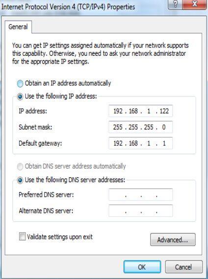
50 Software Using Preparation 1. Network Connection Model: (password ) a) Connect upper machine and lower machine to same LAN by Ethernet cable b) Set the IP address of local connection in network adapter onf upper machine, eg.: i. IP Address: ii. Sub-net Mask: iii. Default Gateway: c) Set the machine IP address in Communication Settings of lower machine, ensure it is the same as LAN segments, eg.: i. IP Address: ii. Sub-net Mask: d) Open the software and select in local IP drop-down list of the network communication(if no IP address in the list, please click "refresh" button laterally). And then all available lower machine IP address in this segment will show in the IP address sequence. The IP above the dialog box will be updated with the selected one after double click on destination IP address, meantime, click 'connect", upper machine software will start communication automatically. 2. COM Connection:(password ) a) Connect upper machine and lower machine with a serial port DB9 cable. 44
51 b) Open the upper machine software, select the connection port in the serial port communication configuration dialog, such as COM3, and click "connection" button, then the upper machine software will start communication automatically. 3. Check Connection Status There is connection status indicator icon in lower right corner in upper machine Red says unconnected, click the red icon to open the connectionconfiguration dialog; green says connected. 45

.")
52 New Project Create New Project Select new project in "File" menu, it come out a create new project dialog box: Screen Type File Name Location Different screen makes difference on the setting in next step LED: no need to consider the frame between screens LCD:LED: no need to consider the frame between screens Name as current local time default, it can be modified as whatever customer like Local save path of project file No. of screens can be set here, mean:no. of output port. Take 12 as an example, set screen No. as 12, several combination will be offered below(no. of row x No. of column, like 4x3 means 4 rowsx 3 column). Select proper combination, click next step, the software will bulid output display automatically, as below images show: 46
 Pos:[5760,1080] Size:[1920,1080] Output screen number: Output port slot number - port type Port number Position of the")
53 Each rectangle stands for output shows three kinds of information, as shown below. Take Screen-3 as an example, the content shown as below: Screen-3:10-DVI A(A1) Pos:[5760,1080] Size:[1920,1080] Output screen number: Output port slot number - port type Port number Position of the output screen in the stage: [Horizontal position, Vertical position] Size of theoutput screen in the stage: [Horizontal size, Vertical size] 47

54 While upper machine software automatically creating output screen, all the screen output resolution is default, which is and the output screen is defaultly full screen. Users can set resolution and output screen of each output screen according to requirement of the projects. Right-click on rectangle that represent output screen, select Screen Properties, it will come out screen parameters adjusting dialog, as shown in the table below: Screen Parameters Output Resolution Output Windows Stitching Parameters In order from left to right is: screen number, screen name, and related output port Output resolution adopted by the output port Setting the size and position of output image This group parameters determine the display scope of current screen in the stage 48

.")
55 Creating New LCD Project While creating new project, suppose the screen type is LCD, after set file name and save location, click the right arrow to next setting, as shown in the image: No. of screens can be set here, namely:number of output port. Take 12 as an example, set the screen number as 12, several kinds of combination will be offered(no. of row x No. of column, eg. 3x4 means 3 row x 4 column). Select proper combination,and convert the seam of LCD into pixels, fill in the seam table below, click next, the software will build output screen automatically, as shown in below image. 49

56 Send output Settings After all the output set, need to send the output of upper machine to the stitching machine. Meanwhile, the sub menu can be called in the stage of output setting, and select "Send output Settings". New Screen Delete Screen Delete All Screens Screen Property Download Output Settings Add new display screen Delete selected screen Delete all screens Open selected screen properties dialog Send current screen data to stitching machine, the machine shall equip all the function of output port; This process will continue for a while, please do not send duplicate output settings, in case increasing the pending time. 50

57 Layer Placement After output setup completed, switch "layer settings" TAB of the stage type, all the screen will display as green dotted box and locked to be not editable. Then the layer can be put on the stage, that is image display configuration. Only after the configuration, related image can be displayed on the displayer or LED Screen. Click on "input resource" on navigation window, menu shown as below image will come out: Drag the image input port to be displayed to the stage with mouse, and place it on the output display area of the screen, then the image can be seen on the display or LED screen, the image can dragged directly to change size or position. Open the layer list window (shown as pictured above) iin the navigation window, drag the layer to be displayed to the stage with mouse or double click related layer switch position, turn the OFF to ON. The value of input source, horizontal starting, vertical start, width, height and transparency in the layer list can be edit by double click the mouse regardless the layer switch is ON or OFF. Therefore,if familiar, we can set the properties first and then double click the layer switch position to switch OFF state to ON 51

58 Save Project After the above process is completed and the lower machine output image normally, it shall be saved. Select and click "Save Project" in the "File" menu, and setup the project name and path, and finally click "save". As shown in below figure: Actually we have already saved project file during the construction.in general, we don't need to save the project deliberately,normally exit PC program after setup is OK, because the upper computer software will save the current project in normal exit. Default project file name is computer local time when creating new project, so user may not clear which one is a project file. Thus, after satisfied with the project Settings, we can use the save project function to save the project in local computer with a more reasonable name and path sepatately, so that we can easily find it in future. 52

59 Open Project Click "Open Project" in "File" menu, and select project file in the dialog box, and click "Open", shown as below figure: All the hardware configuration information of the splicing device and users setting data are saved in the project file. That's offers quick switch between a variety of applications for the splicing device 53


60 Deepen Understanding Relation between stage, stitching parameters and screen parameters Suppose there is a input image, shown as below figure : Four output screen grouped in the form of 2 x 2 and set the height same as width in stitching parameters, then the stage shown as below: Drag the input image into a stage as layers or signal source, and set the size, location to fullfill the four output screen, as shown in the figure below : 54
61 Summary To sum up, the stage is used to present, place all display area, as well as the input image, when he input image overlap with any display area on the stage, the overlap area will display on related output screen. And stitching parameters is what just described. Screen parameters, no signal on the stage, that means screen parameter is related to the display Settings.Detailed speaking, screen parameters only defines what resolution of the video should be output to the display, and which area the image captured by the display stage shall be displayed in the screen. People ever used LED screen can understand why setup like this better. With above principle, users of LED screen can easily realize tiled display of different screens with different pixel pitch, and With above principle, users of LCD screen can easily realize tiled display of different screens with different physical size and resolution. 55

62 Upper Software Interface Detail Layer Interface and Operation Layer No. Input Source Position and Size Transparency Zoom in and Windows mobile The greater the number of layer is, the upper, upper layer will cover lower layers A layer can display an input image signal, such as the layer 2 above, which indicates the input image signal from the input port "7 - VGA B" horizontal starting, vertical start, width and height parameters, determine the location and scope of the signal layer on the stage 0 ~ 255, the greater the value is, the more transparent the layer is, the layer will be completely hidden at the maximum value. The four parameters is aimed at vertical and horizontal of the input signal image layer, it can be 1 to 10 times continuous zoom in, when zoom more than 1 time, layer can only show the input image signal, windows mobile parameters available in this case. 56

63 Layer Group Layer can be divided into eight groups, as shown above, from Group A to Group H Click the icons of the eight group, will come out layer selection interface, as shown in the picture shown above Below each group icons, there are two buttons: "Fade In" and "Fade Out" Click "Fade In" button below the Group A, all layers in it act Fade In Click "Fade Out" button below the Group A, all layers in it act Fade Out The edit box of the fading effect time is on the right side of the "Fade In and Fade Out "button, default time is 1 second 57

64 Related Interface and Operation of Input Source Input Information As shown in above figure, after splicing device hardware information collected while PC software connected, display all the input port information in input information window intensively 58

65 e.g.: 5-DVI A 1920x1080 EDID No Signal AUTO Input port Indicator Input signal resolution EDID function available No signal Indicator Automatic correction availab Image capture available Brightness adjustable Contrast adjustable 59

66 Click on any square of the input port information, it will pop up "input signal information and adjust" dialog box. In this interface, we can adjust the parameters of the current input signal source, including image capture, brightness, contrast, EDID, VGA automatic correction, etc. 60
67 Input Source Information As shown in the above, all the input port of lower machine are listed in the input source information window, if one page shows up, it will be divided into multiple pages, users can switch the current page by the page button in top right of the window If Network display board is unavailable or turned off, the input source information window will be displayed as the below figure. The meaning of Each input source correlation display information shown as below figure: Red light say no effective signal in this input port Green light say effective signal in this input port Change the name by double-click the dark gold character 61


68 Output port related interface and operation Output Information 62

69 Multi-image Preview V. right-click calling shortcut menu I. Multi-preview intention and input source II. Multi-preview Mode List III. Multi-preview Port List IV. Manual Loop- in Port Hint configuration I. Multi-preview intention and input source configuration interface a) Window size, location and input source information are presented intuitively in currently multi-preview mode. b) Please open the window "" input source information [Page 66],if II. need to change the input source in any window and select the preview window then select target signal in the input source window c) Green character represents the input signal is effective, red represents the input signal is invalid Multi-preview Mode List 63
70 a) Each screen preview port of MIG-CL9000 series multiple screen display controller, support maximum 9 tiled images(i.e., 9 images do not overlap each other) b) As many as 64 kinds of preview preinstall mode and custom preview mode, in the custom mode, users can arbitrarily set size, location, etc. of any window. III. Multi-preview Port List a) All the multi-preview port exsited in the device will be shown in the list. b) Please select the target port in the list first if you want to check or change any multi-preview port settings. c) Different model supports different number of mullti-preview ports, please refer to specification of: "CL A", "CL B", "CL C", "CL A" IV. Manual Loop-in Port Hint a) Manual loop-in refers to connect some multi-preview port with some DIV input port by DVI signal cable. b) Manual loop-in port hint, which is dragging target DVI input port from "input source information window" to manual loop-in port prompt window after manully loop-in operation by users, i.g.: Drag 5 - DVI A input port form "input source information window" to "multi-preview" output hint window 64
 Remove preview is used for removing preview window in custom mode d) Preview property is used for calling properties dialog box, as shown in below figure: Location and size parameters of the")
71 V. Right Click Context Menu a) Shortcut menu includes three options: new preview, delete preview, preview properties b) New preview is used for creating new preview window in custom mode. c) Remove preview is used for removing preview window in custom mode d) Preview property is used for calling properties dialog box, as shown in below figure: Location and size parameters of the preview window Image crop function aimed at related input signal source of the window 65


72 Scenario related interface and operation Scene Settings I. New scene file, click on the green plus sign documents icon to create new scene file II. Save current settings to a scene file, click on a scene file, make its name appeared as yellow, and click "save to the selected file" III. Remove a scene file, click on the red minus sign on the scene file icon IV. If too many scene files can't be displayed on one page of "Scene setting" window, it may be divided into multiple pages, please click on the button in the top right corner of the page to switch. Scene Switching I. Scene switching, i.e., send all information that saved in scene file to lower machine device to update it's working status, so that users can realize rapid switching of the device. II. Double-click a scene file for rapidly scene switch. If users are not sure which scene file should be switched to, please click on the "preview" button at the top right of the window and switch to the"scene preview". 66

73 Scene Preview Ⅰ. Scene preview provides function of preview the scene file, it's used to add information that saved in the scene file to the upper machine interface, so that users can see general effect of the scene, and the these settings will not be sent to the stitching machine by this time Ⅱ. Double-click a file if the scene file need to be previewed When user confirmed need to load a scene after preview or any other effective access, please click on "Switch button" at the window to "Scene Switch" and double-click the file. Interface of System State Upper machine software can monitor system, so users can check the system state real time. As above figure shows, the state includes: system temperature, electrical state, hardware state, fan state, firmware version, etc. 67
74 Warranty The whole unit warranty One year(from the buying date); If the invoice is lost, the 60 days after the production date will be the warranty start date for the product. The non-warranty provisions The machine soaking and collisions produced besmirch or surface scratches and other abnormal using causes of malfunction or damage; Demolition machine or modification, which is not to be agreed by our company; Using in the not specified used working conditions, resulting in fault of damage (such as high temperature, low voltage or unstable etc.); Force majeure(such as fire, earthquake, etc) or natural disasters(like lighting, etc) caused the fault or damage; Expired the product warranty. 68
75 Quick use guide Step one: installing software Read the data in the U disk, open the install program to start installing,v1.041x is the version Number of the software. Double click and the following installing interface will appear, click next to continue, until the accomplishing interface occurs. Step two: connect video wall controller (1) network connection Use cable to connect the video wall controller and host computer directly, make both of them in the same local area network. Note: only to ensure that IP address of host computer and video wall controller in the same network segment, modify the IP address of host computer as follows (IP address xx; subnet mask ) 69

76 70


77 Double click icon in your desktop,open the software connection window, click network connection, the original login password is After login, a graph appears as follows: Video wall controller inherent IP address, no need to modify. Host computer IP address 71
 COM connection Use serial port cable to connect the machine to host computer or the other controlling device, click COM connection.")
78 After the correct local IP address selected, please click connect button Host computer software connection indicator in the bottom right of the interface. the green light keeps on when system connected successfully (2) COM connection Use serial port cable to connect the machine to host computer or the other controlling device, click COM connection. The login password is , the following interface will appear. Select the correct COM port, and click connect button. Choose COM Port 72


79 Step three: create new project Click the toolbar,file,new project select the type of screen controlled 73


80 The number of parts to be spliced for the large screen. It means to put a few separate screens together, in this case the number of screens needs to be input, for example, a screen that needs 4 sending cards, and number 4 needs to be entered. Select splicing configuration, for example 2 4, means that 2 tiers in height and 4 tiers in width. Click to continue, a menu appears as below: The default resolution and size of window for each output port is 1920*1080 Select one output and right click, enter the screen property setting to set parameters of each output. 74

81 Set current output port resolution Select output port corresponding to the screen needed to correct parameters. The three groups parameters need to be corrected to be identical with size of current output port which loads LED screen 75


82 After the parameters of all the output port has been set successively, right click, select download output settings After sending process accomplished, get into layer setting interface automatically, click the layer setting menu in the bottom left, all the previous output settings has become dotted box. 76


83 Select input information in the navigation menu to load the input signal source. Input source status, green means signal is available Use mouse to click one channel input source, then press the left key of the mouse to drag the source to the output. Thus we can achieve large spicing display requirements. Double click the layer, it can achieve quick full screen to this output port. 77

84 If you need to modify the size and position of one signal source, select the signal source layer, the click the layer information in navigation bar to correct. Layer size and position Current input signal 78

85 Step four: save and load presets When all the parameters have been set correctly, you can save all the current data and to store it as a preset, and it would be convenient for later loading and quicker switching. Find configuration--preset configuration item in the toolbar, the preset loading and saving interface will appear in the drop-down menu, graph as below. Preset name Load preset Save preset Or you can proceed relevant operation about presets in the file---save/load presets menu. 79
VENUS X1PRO-E Quick Start
 VENUS X1PRO-E Quick Start 4K input support in DP, HDMI and Dual Link DVI Support 8K x 1K, 4K x 2K Seamless Splicing EDID management Modular 2K input: Three slots for 2K input options 2K-2K and/or 4K-2K
J6 User Manual. User Manual. Multi-Screen Splicing Processor J6. Xi an NovaStar Tech Co., Ltd. Rev1.0.1 NS
 J6 User Manual User Manual Multi-Screen Splicing Processor J6 Rev1.0.1 NS160110162 Statement Dear users, You are welcome to use the J6, a multi-screen splicing processor of Xi'an NovaStar Tech Co., Ltd.
User Manual. Multi-Screen Splicing Processor J6
 User Manual Multi-Screen Splicing Processor J6 Rev1.0.0 NS160100147 Statement Dear users, Welcome to use the J6, a multi-screen splicing processor. This manual is intended to help you to understand and
VSP 198CVS Quick Start
 VIEWSIZE THE WORLD VSP 198CVS Quick Start Max 2048 1152@60Hz/2560 1152 50Hz input/output resolution User customize output resolution 3G/HD/SD-SDI input Multiple cascade mapping for super resolution DVI
Multi-Screen Splicing Video Processor. Xi an NovaStar Tech Co., Ltd. Specifications. Document Version: Document Number:
 N9 Multi-Screen Splicing Video Processor Document Version: V1.0.0 Document Number: Copyright 2018 All Rights Reserved. No part of this document may be copied, reproduced, extracted or transmitted in any
Statement SmartLCT User s Manual Welcome to use the product from Xi an NovaStar Tech Co., Ltd. (hereinafter referred to as NovaStar ). It is our great
. It is our great") LED Display Configuration Software SmartLCT User s Manual Software Version: V3.0 Rev3.0.0 NS110100239 Statement SmartLCT User s Manual Welcome to use the product from Xi an NovaStar Tech Co., Ltd. (hereinafter
LED Display Configuration Software SmartLCT User s Manual Software Version: V3.0 Rev3.0.0 NS110100239 Statement SmartLCT User s Manual Welcome to use the product from Xi an NovaStar Tech Co., Ltd. (hereinafter
VSP 168HD Quick Start
 VSP 168HD Quick Start Support 10Gbps of transmission rate Support HDBaseT protocols and standards Support USB upgrade Max 2048 1152@60Hz/2560 816 60Hz input/output resolution Support custom output resolution
Statement Dear users: Welcome to use Nova's Products. We are pleased to offer this manual to help you understand and use the product. In the preparati
 User's Manual LED Display Video Controller VX4 VX4S Rev1.0.0 NS160100018 Statement Dear users: Welcome to use Nova's Products. We are pleased to offer this manual to help you understand and use the product.
Xi an NovaStar Tech Co., Ltd. User's Manual. LED Video Controller VX4S/VX4. Rev1.1.2 NS
 User's Manual LED Video Controller VX4S/VX4 Rev1.1.2 NS160110080 Statement You are welcome to use the products from (hereinafter referred to as Novastar). It is our great pleasure to offer this manual
VSP 516S Quick Start
 VIEWSIZE THE WORLD VSP 516S Quick Start Max 2048 1152@60Hz/2560 816 60Hz input/output resolution User customize output resolution 3G/HD/SD-SDI input Multiple cascade mapping for super resolution Seamless
Statement Welcome to use the product from Xi an NovaStar Tech Co., Ltd. (hereinafter referred to as Novastar ). It is our great pleasure to offer this
. It is our great pleasure to offer this") User's Manual LED Display Video Controller VX2U/VX4U XI'AN NOVASTAR TEC Rev1.0.3 NS160100228 Statement Welcome to use the product from Xi an NovaStar Tech Co., Ltd. (hereinafter referred to as Novastar
User's Manual LED Display Video Controller VX2U/VX4U XI'AN NOVASTAR TEC Rev1.0.3 NS160100228 Statement Welcome to use the product from Xi an NovaStar Tech Co., Ltd. (hereinafter referred to as Novastar
CCE900-IP-TR. User s Guide
 CCE900-IP-TR CCE900-IP-T & CCE900-IP-R User s Guide i-tech Company LLC TOLL FREE: (888) 483-2418 EMAIL: info@itechlcd.com WEB: www.itechlcd.com 1. Introduction The CCE900-IP-T & CCE900-IP-R is a solution
Scaler Video Processor
 Scaler Video Processor User Manual! Before using this Scaler Video processor please read this manual carefully and preserved for reference in the future. Model Dcdi 550 Statements Without the written permission,
LED-780H. 4K 2K Video Processor. User Manual V1.2. read this manual carefully and preserved for reference in the future.
 4K 2K Video Processor User Manual V1.2! Before using this LED Video processor,please read this manual carefully and preserved for reference in the future. LED-780H Statements Without the written permission,
MAGNIMAGE. LED Video Processor User Manual V1.1. LED-570E series
 LED Video Processor User Manual V1.1! Before using this LED Video processor,please read this manual carefully and preserved for reference in the future. MAGNIMAGE LED-570E series Statements Without the
Copyright 2018 Xi an NovaStar Tech Co., Ltd. All Rights Reserved. No part of this document may be copied, reproduced, extracted or transmitted in any
 MCTRL660 PRO Independent Controller Product Version: Document Number: V1.0.0 NS110100560 Copyright 2018 Xi an NovaStar Tech Co., Ltd. All Rights Reserved. No part of this document may be copied, reproduced,
Digital Video Recorder
 Digital Video Recorder Quick Operation Guide UD.6L0202B0067A02 Thank you for purchasing our product. If there is any question or request, please do not hesitate to contact dealer. This manual is applicable
Statement Welcome to use the product from Xi an NovaStar Tech Co., Ltd. (hereinafter referred to as Novastar ). It is our great pleasure to offer this
. It is our great pleasure to offer this") User's Manual LED Display Video Controller VX Series Rev1.0.0 NS160100130 Statement Welcome to use the product from Xi an NovaStar Tech Co., Ltd. (hereinafter referred to as Novastar ). It is our great
User's Manual LED Display Video Controller VX Series Rev1.0.0 NS160100130 Statement Welcome to use the product from Xi an NovaStar Tech Co., Ltd. (hereinafter referred to as Novastar ). It is our great
LM-WPS41 HD Caption Adder. User. Manual
 LM-WPS41 HD Caption Adder User Manual 1 Table of Contents 1. Installation Notes 3 2.Product Introduction 5 3. Machine installation 7 4. Software debugging 8 5. Remote Control Description 12 Chapter One
G3 NET 2K USER MANUAL
 G3 NET 2K USER MANUAL Article No: RGB-RD-UM-G3 NET 2K E001 Revision No: V1.0 CONTENTS CONTENTS... 1 Declarations... 3 FCC/Warranty... 3 Operators Safety Summary... 4 Installation Safety Summary... 4 Chapter
LedSet User s Manual V Official website: 1 /
 LedSet User s Manual V2.6.1 1 / 42 20171123 Contents 1. Interface... 3 1.1. Option Menu... 4 1.1.1. Screen Configuration... 4 1.1.1.1. Instruction to Sender/ Receiver/ Display Connection... 4 1.1.1.2.
Table of Contents TABLE OF CONTENTS. Vivid Drive 23N User Manual Rev. 1
 User Manual TABLE OF CONTENTS Table of Contents 1. Before You Begin... 1 What Is Included... 1 Unpacking Instructions... 1 Claims... 1 Text Conventions... 1 Symbols... 1 Disclaimer... 1 Safety Notes...
Video Processor HDP703 HDP602. Introduction V
 Video Processor HDP703 HDP602 V1.2 20171218 Introduction About LED Video Processor LED video processor is a mid-market seamless handover effects video processor, it supports high definition digital input,
Specifications LED Display Video Controller VX4S
 Specifications LED Display Video Controller VX4S Rev1.0.3 NS160110155 General The VX4S is a professional LED display controller. Besides the function of display control, it also features in powerful front
Specifications LED Display Video Controller VX4. Xi an NovaStar Tech Co., Ltd. Rev1.0.4 NS
 Specifications LED Display Video Controller VX4 Rev1.0.4 NS160110153 General Feature The VX4 is a professional LED display controller. Besides the function of display control, it also features in powerful
DS-7200HVI/HFI-SH Series DVR Quick Operation Guide
 DS-7200HVI/HFI-SH Series DVR Quick Operation Guide UD.6L0202B0019A01 Thank you for purchasing our product. If there is any question or request, please do not hesitate to contact dealer. This manual is
THD601DC Set-top box
 THD601DC Set-top box Contents 1. Safety... 1 2. Appearance... 2 3. Rear Panel Connection... 3 4. Remote... 4 5 First Time Set-Up... 7 6. Network Settings... 8 6.1 Available Networks and Checking Current
Manual Version Ver 1.0
 The BG-3 & The BG-7 Multiple Test Pattern Generator with Field Programmable ID Option Manual Version Ver 1.0 BURST ELECTRONICS INC CORRALES, NM 87048 USA (505) 898-1455 VOICE (505) 890-8926 Tech Support
Projector Management Application Version 7.00 Instruction Guide
 Projector Management Application Version 7.00 Instruction Guide Contents 1 INTRODUCTION... 4 1.1 OUTLINE... 4 1.2 SYSTEM... 4 2 INSTALLATION... 5 2.1 SYSTEM REQUIREMENTS... 5 2.2 PROJECTOR MANAGEMENT APPLICATION
Operating Instructions
 Marshall Electronics Broadcast A/V Division Model No. VSW-2200 4-Input Seamless SDI A/V Switcher Operating Instructions Table of Contents 1. Overview... 2. Features.... Package Contents... 4. Specifications...
Marshall Electronics. Pro A/V Communications VMV-402-SH. 3G/HD/SD-SDI Quad-viewer/Switcher with Audio Meter Display. User Manual.
 Marshall Electronics Pro A/V Communications VMV-402-SH 3G/HD/SD-SDI Quad-viewer/Switcher with Audio Meter Display User Manual Table of Contents 1. Introduction... 3 2. Features... 3 3. Package Contents...
OPERATING GUIDE. HIGHlite 660 series. High Brightness Digital Video Projector 16:9 widescreen display. Rev A June A
 OPERATING GUIDE HIGHlite 660 series High Brightness Digital Video Projector 16:9 widescreen display 111-9714A Digital Projection HIGHlite 660 series CONTENTS Operating Guide CONTENTS About this Guide...
42 Freestanding Infrared Multi Touch Screen Kiosk User s Manual
 42 Freestanding Infrared Multi Touch Screen Kiosk User s Manual Manual Version L42HD-T2.2 Safety Instructions Please keep the display away from any heat sources such as radiators or direct sunlight. Place
V9A01 Solution Specification V0.1
 V9A01 Solution Specification V0.1 CONTENTS V9A01 Solution Specification Section 1 Document Descriptions... 4 1.1 Version Descriptions... 4 1.2 Nomenclature of this Document... 4 Section 2 Solution Overview...
LVP602S LED Video Processor USER S MANUAL
 LVP602S LED Video Processor USER S MANUAL TABLE OF CONTENTS I. Safety precautions 3 II. Connections of hardware 1.Rear view 4 2. Port description 4 III. Frontal panel operations 1. Diagram of frontal panel
VSP 9516S Quick Start
 VIEWSIZE THE WORLD VSP 9516S Quick Start Max 2048 1152@60Hz/2560 816 60Hz input/output resolution User-defined resolution adjustment Picture in picture Audio and video sync Seamless switching between inputs
Quick Operation Guide of LTN7700/7600 Series NVR
 Quick Operation Guide of LTN7700/7600 Series NVR UD.6L0202B0042A02 Thank you for purchasing our product. If there is any question or request, please do not hesitate to contact dealer. This manual is applicable
Statement Dear users: Welcome to use Nova's Products. We are pleased to offer this manual to help you understand and use the product. In the preparati
 User's Manual LED Display Video Controller VX4S VX4 Rev1.0.0 NS160100018 Statement Dear users: Welcome to use Nova's Products. We are pleased to offer this manual to help you understand and use the product.
MAGNIMAGE. LED Video processor LED-540. User manual
 LED Video processor User manual! Before using this LED Video processor, please read the instruction carefully and preserved for reference in the future. MAGNIMAGE LED-540 Statements Without the written
FLAT DISPLAY TECHNOLOGY
 15.0 Open Frame Monitor Model Number: LOF1506xx This product is RoHS compliant SPEC No.: SAS-1008002 Version: 0.0 Issue Date: September 6, 2010 1. Introduction: 1.1 About the Product The LOF1506xx 15.0
Specifications. Independent Controller MCTRL R5. Rev1.0.0 NS
 Specifications Independent Controller MCTRL R5 Rev1.0.0 NS1601000126 Overview MCTRL R5 is an independent master controller developed by NovaStar with an epoch-making significance. The loading capacity
Broadcast A/V Division M-LYNX-702 V.3. Dual 7 LCD Display. User Manual
 Broadcast A/V Division M-LYNX-702 V.3 Dual 7 LCD Display User Manual 1. Package Includes Table of Contents 1. Package Includes Table of Contents 01 02 One M-LYNX-702 Monitor One universal AC power adapter
CONTENT Product Introduction... 2 Packing Configuration...3 Hardware Orientation... 4 Front Panel... 4 Back Panel... 6 Using Your Product... 7 Content
 VENUS X1PRO Quick Start 4K input support in DP, HDMI and DVI Input standard 2K formats Scale and switch seamlessly between 2K and 4K inputs Output to any format 2K or 4K EDID management on board HDCP 2.0
RMS 8424S Quick Start
 VIEWSIZE THE WORLD RMS 8424S Quick Start Standard 4 unit rack mount size 8 inch LCD 2 1024 3 (RGB) 600 16:9 / 4:3 adjustable SDI/HDMI embedded audio output via 3.5mm earphone socket Support SDI/DVI audio
Model: S-1071H(EFP) 7" EFP Field On-camera LCD Monitor. User Manual. Please read this User Manual throughout before using.
 7 EFP Field On-camera LCD Monitor. User Manual. Please read this User Manual throughout before using.") Model: S-1071H(EFP) 7" EFP Field On-camera LCD Monitor User Manual Please read this User Manual throughout before using. Preface Congratulations on your purchase of this product. Please read this user
Model: S-1071H(EFP) 7" EFP Field On-camera LCD Monitor User Manual Please read this User Manual throughout before using. Preface Congratulations on your purchase of this product. Please read this user
Displays Open Frame Monitor Model Number: AND-TFT-150Bxx
 Displays 15.0 Open Frame Monitor Model Number: AND-TFT-150Bxx The AND-TFT-150Bxx 15.0 Open Frame Monitor series are rugged, high performance Industrial LCD Monitors, designed for commercial and industrial
Intelligent Security and Fire Ltd
 User Manual Product ranges covered by this manual Vi-P14 Vi-P14A Document Reference Date Firmware Vi-Q4C1 Viq601a.doc 26/11/2009 From Viq001a21 Videoswitch Telephone 01252-851510 Ocean House, Redfields
DINOX&Digital&Video&Recorder&
 DINOX&Digital&Video&Recorder& & & & & & & & & & &&&Quick&Operation&Guide& UD.7L0X02B1228B01& Thank you for purchasing our product. If there is any question or request, please do not hesitate to contact
VENUS X3 LIVE USER MANUAL USER MANUAL
 VENUS X3 LIVE USER MANUAL USER MANUAL Article No: RGB-RD-UM-X3 LIVE E001 Revision No: V1.0 CONTENTS CONTENTS... 1 Declarations... 3 FCC/Warranty... 3 Operators Safety Summary... 4 Installation Safety Summary...
IP LIVE PRODUCTION UNIT NXL-IP55
 IP LIVE PRODUCTION UNIT NXL-IP55 OPERATION MANUAL 1st Edition (Revised 2) [English] Table of Contents Overview...3 Features... 3 Transmittable Signals... 3 Supported Networks... 3 System Configuration
LM-TV09-4K2K. 4K video wall controller. User. Manual
 LM-TV09-4K2K 4K video wall controller User Manual Catalog 1.Installation Instructions 1 2.Product Brief 2 3.Controller Installed 3 4.Remote Control Settings 6 5.Pressing Setting 7 6.Specifications 7 1
Table of content. Table of content Introduction Concepts Hardware setup...4
 Table of content Table of content... 1 Introduction... 2 1. Concepts...3 2. Hardware setup...4 2.1. ArtNet, Nodes and Switches...4 2.2. e:cue butlers...5 2.3. Computer...5 3. Installation...6 4. LED Mapper
Broadcast A / V Division M-LYNX-702 V.3. Dual 7 LCD Display. User Manual
 Broadcast A / V Division M-LYNX-702 V.3 Dual 7 LCD Display User Manual Table of Contents Table of Contents 1. Package Includes 2. Product Description 2.1 Front Panel 2.2 Rear Panel Connections 3. On-Screen
VENUS X1 USER MANUAL
 VENUS X1 USER MANUAL Article No: RGB-RD-UM-X1 E001 Revision No: V1.5 CONTENTS CONTENTS... 1 Declarations... 3 FCC/Warranty... 3 Operators Safety Summary... 4 Installation Safety Summary... 4 Chapter 1
EdgeConnect Module Quick Start Guide ITERIS INNOVATION FOR BETTER MOBILITY
 EdgeConnect Module Quick Start Guide ITERIS INNOVATION FOR BETTER MOBILITY 493456301 Rev B April 2009 Table of Contents Installation... 1 Setup... 2 Operation... 4 Live Video... 4 Video Settings... 5 Network
DP Tuner 80 Remote Control Software User Manual. Version:08 Issue Date:May 10, 2018
 DP Tuner 80 Remote Control Software User Manual Version:08 Issue Date:May 10, 2018 Copyright Information Copyrights Lumens Digital Optics Inc. All rights reserved. Lumens is a registered trademark of Lumens
First Time Setup Guide
 First Time Setup Guide www.exhibio.com 1.877.EXHIBIO (394.4246) Exhibio ST-200 Components & Accessories Standing Mount TV Tuner with Input Cable (USB 2.0 only) VESA Mount Over-the-Air Antenna Power Adapter
USER MANUAL. 22" Class Slim HD Widescreen Monitor L215DS
 USER MANUAL 22" Class Slim HD Widescreen Monitor L215DS TABLE OF CONTENTS 1 Getting Started Package Includes Installation 2 Control Panel / Back Panel Control Panel Back Panel 3 On Screen Display 4 Technical
Copyright 2018 Xi an NovaStar Tech Co., Ltd. All Rights Reserved. No part of this document may be copied, reproduced, extracted or transmitted in any
 MCTRL4K Independent Controller Product Version: Document Number: V1.0.3 NS110100428 Copyright 2018 Xi an NovaStar Tech Co., Ltd. All Rights Reserved. No part of this document may be copied, reproduced,
IRIG-B PTP Clock Converter Output Module Hardware Installation Manual
 IRIG-B PTP Clock Converter Output Module Hardware Installation Manual Kyland Technology Co., LTD. Publication Date: May 2012 Version: V1.2 Customer Service Hotline: (+8610) 88796676 FAX: (+8610) 88796678
32 Channel Auto Searching Wireless FPV Monitor with Dual Receiver LCD Monitor. User Manual
 32 Channel Auto Searching Wireless FPV Monitor with Dual Receiver LCD Monitor User Manual Product description: Wireless FPV monitor with dual receiver LCD monitor is a new multi-function product; adopts
DXP A0808 Quick Start
 VIEWSIZE THE WORLD DXP A0808 Quick Start Support any in any out Support independent output switching Support infrared remote control Input and output can be modularized RS 232 loop out for multiple control
FS1-X. Quick Start Guide. Overview. Frame Rate Conversion Option. Two Video Processors. Two Operating Modes
 FS1-X Quick Start Guide Overview Matching up and synchronizing disparate video and audio formats is a critical part of any broadcast, mobile or post-production environment. Within its compact 1RU chassis,
EVD-L04/100A1-960, EVD-L08/200A1-960 and. EVD-L16/400A1-960 DVRs. Quick Operation Guide
 EVD-L04/100A1-960, EVD-L08/200A1-960 and EVD-L16/400A1-960 DVRs Quick Operation Guide Thank you for purchasing our product. If there is any question or request, please do not hesitate to contact dealer.
CP-255ID Multi-Format to DVI Scaler
 CP-255ID Multi-Format to DVI Scaler Operation Manual DISCLAIMERS The information in this manual has been carefully checked and is believed to be accurate. Cypress Technology assumes no responsibility
6.4 Chassis Monitor Model Number: LCM0642xx. SPEC No.: SAS Version: 0.0 Issue Date: April 16, Introduction:
 6.4 Chassis Monitor Model Number: LCM0642xx This product is RoHS compliant SPEC No.: SAS-0908003 Version: 0.0 Issue Date: April 16, 2010 1. Introduction: 1.1 About the Product The LCM0642xx 6.4 Chassis
FS3. Quick Start Guide. Overview. FS3 Control
 FS3 Quick Start Guide Overview The new FS3 combines AJA's industry-proven frame synchronization with high-quality 4K up-conversion technology to seamlessly integrate SD and HD signals into 4K workflows.
Model: S-1071H 7" Broadcast On-camera 3GSDI&HDMI LCD Monitor. User Manual. Please read this User Manual throughout before using.
 Model: S-1071H 7" Broadcast On-camera 3GSDI&HDMI LCD Monitor User Manual Please read this User Manual throughout before using. Preface Congratulations on your purchase of this product. Please read this
USER MANUAL USER MANUAL. VIO 4K Ref. V701 PROGRAMMER S GU.
 USER MANUAL VIO 4K Ref. V701 1 Table of Contents 1 Introduction... 6 1.1 Why use the VIO 4K?... 6 1.2 VIO 4K at a glance... 6 1.3 Key features... 6 1.4 Inputs... 7 1.5 Outputs... 7 1.6 Universal system
P-2 Installing the monitor (continued) Carry out as necessary
 Carry out as necessary") P-2 Installing the monitor (continued) Carry out as necessary Using the monitor without the bezel MDT552S satisfies the UL requirements as long as it is used with the bezel attached. When using the monitor
P-2 Installing the monitor (continued) Carry out as necessary Using the monitor without the bezel MDT552S satisfies the UL requirements as long as it is used with the bezel attached. When using the monitor
USER MANUAL. Article No: RGB-RD-UM-M3 E001 Revision No: V1.0
 M3 USER MANUAL USER MANUAL Article No: RGB-RD-UM-M3 E001 Revision No: V1.0 CONTENTS CONTENTS... 1 Declarations... 1 FCC/Warranty...1 Operators Safety Summary...2 Installation Safety Summary...2 Chapter
VS-TV. User manual. Virtual Matrix ENGLISH
 ENGLISH VS-TV User manual Virtual Matrix INDEX 1 INTRODUCTION... 2 1.1 FEATURES.... 2 2 INSTALLATION AND SET UP... 3 2.1 UNIT PACKAGE CONTENTS... 3 2.2 INSTALLATION... 3 2.3 UNIT SET UP... 3 3 CONFIGURATION
INFORMATION TO USER CAUTION RISK OF ELECTRIC SHOCK, DO NOT OPEN
 INFORMATION TO USER CAUTION RISK OF ELECTRIC SHOCK, DO NOT OPEN! CAUTION: TO REDUCE THE RISK OF ELECTRIC SHOCK, DO NOT REMOVE COVER (OR BACK). NO USER SERVICEABLE PARTS INSIDE. REFER SERVICING TO QUALIFIED
Simple Media Platform Quick Installation Guide V1.0-N. Simple Media Platform. Quick Installation Guide
 Simple Media Platform Quick Installation Guide 1. Installation Instruction 1.1 Mounting unit to a 19 rack When selecting the installation site, try to comply with the following: Protective Ground - The
D-Lab & D-Lab Control Plan. Measure. Analyse. User Manual
 D-Lab & D-Lab Control Plan. Measure. Analyse User Manual Valid for D-Lab Versions 2.0 and 2.1 September 2011 Contents Contents 1 Initial Steps... 6 1.1 Scope of Supply... 6 1.1.1 Optional Upgrades... 6
GeChic Corporation 13F.-4, No.367, Gongyi Road, West District, Taichung City 403 Taiwan (R.O.C.) Customer Service:
 Customer Service:") GeChic Corporation 13F.-4, No.367, Gongyi Road, West District, Taichung City 403 Taiwan (R.O.C.) Customer Service: +886-4-23198080 Monitor for Laptop 1301 User Manual Table of Contents Chapter 1 Content
GeChic Corporation 13F.-4, No.367, Gongyi Road, West District, Taichung City 403 Taiwan (R.O.C.) Customer Service: +886-4-23198080 Monitor for Laptop 1301 User Manual Table of Contents Chapter 1 Content
CP 3072S Quick Start
 VIEWSIZE THE WORLD CP 3072S Quick Start 4 channels, 16 signal sources Preview and program outputs separately PIP between any two inputs Seamless switching between any two channels Seamless switching between
LVP603S LED Video Processor USER S MANUAL
 LedControlCard.com Focus On led card and led video processor LVP603S LED Video Processor USER S MANUAL www.ledcontrolcard.com led control website. TABLE OF CONTENTS I. Safety precautions 3 II. Connections
YCbCr (480i/576i) and RGBsync. 4 Press Component to change source to component connec tor. This connector supports YPbPr (480p/576p/720p/1080i)
 and RGBsync. 4 Press Component to change source to component connec tor. This connector supports YPbPr (480p/576p/720p/1080i)") Introduction Product Features This product is an XGA single chip 0.7 DLP TM projector. Outstanding features include: u True XGA, 1024 x 768 addressable pixels u Single chip DLP TM technology u NTSC3.58/NTSC4.43/PAL/SECAM
Introduction Product Features This product is an XGA single chip 0.7 DLP TM projector. Outstanding features include: u True XGA, 1024 x 768 addressable pixels u Single chip DLP TM technology u NTSC3.58/NTSC4.43/PAL/SECAM
User s Manual For LDU8000R
 Contents 1. Introduction of LDU8000R... 4 2. Hardware... 5 2.1 Control Buttons and Output Ports... 5 2.2 Cables... 7 3. Application... 9 3.1 One Display Controlled By One LDU... 9 3.2 Four Displays Controlled
VIDEO GRABBER. DisplayPort. User Manual
 VIDEO GRABBER DisplayPort User Manual Version Date Description Author 1.0 2016.03.02 New document MM 1.1 2016.11.02 Revised to match 1.5 device firmware version MM 1.2 2019.11.28 Drawings changes MM 2
Precautions and Disclaimers What You Can Do with Geometry Manager Pro Check Your Computer System requirements...
 Operating Instructions Geometric & Setup Management Software Windows Geometry Manager Pro Ver. 4.0 Thank you for purchasing this Panasonic product. Before using this software, please read the instructions
Video Extender DS128 DSRXL. Instruction Manual. 8-Port Cat5 VGA Digital Signage Broadcaster with RS232 and Audio
 DS128 DSRXL Instruction Manual Video Extender 8-Port Cat5 VGA Digital Signage Broadcaster with RS232 and Audio Cat5 VGA Digital Signage Receiver with RS232 and Audio FCC Compliance Statement This equipment
USER MANUAL. 27 Full HD Widescreen LED Monitor L27ADS
 USER MANUAL 27 Full HD Widescreen LED Monitor L27ADS TABLE OF CONTENTS 1 Getting Started 2 Control Panel/ Back Panel 3 On Screen Display 4 Technical Specs 5 Care & Maintenance 6 Troubleshooting 7 Safety
Package Contents. LED Protocols Supported. Safety Information. Physical Dimensions
 Pixel Triton Table of Contents Package Contents... 1 Safety Information... 1 LED Protocols Supported... 1 Physical Dimensions... 1 Software Features... 2 LED Status... 2 Power... 2 Activity LED... 2 Link
User Manual. 7" Portable On-camera LCD Monitor DT-X71H DT-X71C. Model: DT-X71F HDSDI&HDMI, Waveform, Audio meter, Focus assist HDSDI&HDMI HDMI
 7" Portable On-camera LCD Monitor User Manual Model: DT-X71F HDSDI&HDMI, Waveform, Audio meter, Focus assist DT-X71H DT-X71C HDSDI&HDMI HDMI Please read this User Manual throughout before using. Preface
VSP 628PRO USER MANUAL
 VSP 628PRO USER MANUAL Article No: RGB-RD-UM-V628PRO E001 Revision No: V2.0 CONTENTS CONTENTS... 1 Declarations... 3 FCC/Warranty... 3 Operators Safety Summary... 4 Installation Safety Summary... 4 Chapter
Z-IP Stream 004/008. User Guide and Installation Manual. Four or Eight Input QAM Encoder / Modulator
 Z-IP Stream 004/008 User Guide and Installation Manual Four or Eight Input QAM Encoder / Modulator MPEG-2 / H.264 HD ENCODER with QAM /IP/ & ASI Outputs Contents Safety Precautions... 3 Package Contents...
DVI Video Processing Switcher 4x4 USER MANUAL MV4. PTN DVI Video Processing Switcher 4x4. Version: MV42013V1.4
 USER MANUAL MV4 PTN DVI Video Processing Switcher 4x4 Version: MV42013V1.4 PTN Electronics Limited www.ptn-electronics.com NOTICE: Please read this user manual carefully before using this product. This
User Instruction Manual IQSDA30/IQSDA32. Intelligent Reclocking High Performance HD-SDI/SD-SDI Distribution Amplifiers. snellgroup.
 User Instruction Manual IQSDA30/IQSDA32 Intelligent Reclocking High Performance HD-SDI/SD-SDI Distribution Amplifiers snellgroup.com IQSDA30/IQSDA32 www.snellgroup.com Information and Notices Information
EAN-Performance and Latency
 EAN-Performance and Latency PN: EAN-Performance-and-Latency 6/4/2018 SightLine Applications, Inc. Contact: Web: sightlineapplications.com Sales: sales@sightlineapplications.com Support: support@sightlineapplications.com
Part 1 Basic Operation
 This product is a designed for video surveillance video encode and record, it include H.264 video Compression, large HDD storage, network, embedded Linux operate system and other advanced electronic technology,
EDITION NOTES. Document Revision
 User Manual EDITION NOTES The VIP Drive 43Nova User Manual includes a description, safety precautions, installation, programming, operation, and maintenance instructions for the VIP Drive 43Nova as of
MSP 200PRO Quick Start
 MSP 200PRO Quick Start Touch Screen control Output a range of signal types Set and select from a range of common output formats Audio output test included Genlock Y&HS outputs Input live signals for preview
Video Wall Display User s Manual
 Video Wall Display User s Manual Manual Version TL46-55H1.1 Our Full Product Range Page 1 Safety Instructions Please handle the display with extreme care, significant impact will damage the LCD panel.
Multi-Image Splicing Processor
 1. KYStar KS928 Multi-Image Splicing Processor Multi-Image Splicing Processor Operation Manual Statement 1. KYStar KS928 Multi-Image Splicing Processor Thank you for choosing our products. All rights of
HD-1603 Single Input MPEG-4 DVB-T HD Encoder/Modulator User Guide and Install Manual
 ZyCastR digi-mod HD Range digi-mod HD-1603 www.digi-modbyzycast.com HD-1603 Single Input MPEG-4 DVB-T HD Encoder/Modulator User Guide and Install Manual Table of Contents www.digi-modbyzycast.com Safety
Video Server SED-2100R/S. Quick Installation Guide
 Video Server SED-2100R/S Quick Installation Guide Feb.10,2006 1 1 Getting Started 1.1 PACKAGE CONTENTS SED-2100 Warranty Card Software CD Hook up & Screws Terminal Blocks for Power & DI/O Power Adaptor
CATALOG NUMBER: HK-MX-VGA-X-Y Product Name
 Product Name Screen matrix switcher Describe Matrix switcher is a high-performance intelligent matrix switch device designed for switching of audio and video signals. It switches all audio and video input
LedSync820C LED Video Processor USER S MANUAL
 LedSync820C LED Video Processor USER S MANUAL TABLE OF CONTENTS I. Safety precautions ----------------------------------------------------------------- 3 II. Connections of hardware 1.Rear view ------------------------------------------------------------