FLASH FLASH. User s Guide TFT 16:10
|
|
|
- Alexina Constance Hart
- 5 years ago
- Views:
Transcription


1 FLASH FLASH User s Guide 7.0 TFT 16:10


2 Get to know your HD FLASH FRONT PANEL power To turn on press the HOME key. to turn off press and hold the HOME key WHEEL Use the wheel to navigate across the screen and vary the values Rotate to Navigate Touch to Select Press and HOLD RESET HARDWARE RESET SOFTWARE Keep the HOME key pressed for 10 and turn on again + Switch on the meter, immediately after keep the volume key pressed until a beep is heard 2

 4 = Common Interface slot for CAM module 5 6 7 8 9 Left side 5 = Power supply")

3 Side Panels RIGHT side 1 = Remote bypass switch - DC at RF IN ON/OFF 2 = IF/RF input connector, F type, 75 Ω 3 = Optic input connector, interchangeable type TC-ST & SC (opt.) 4 = Common Interface slot for CAM module Left side 5 = Power supply input connector (12 V DC - 3A) 6 = analog Audio - Video input connector 7 = analog audio - video output connector 8 = HDMI output connector 9 = OTG usb micro socket for SW upgrades and memory plans AUDIO - VIDEO IN/OUT CONNECTION diagram 3


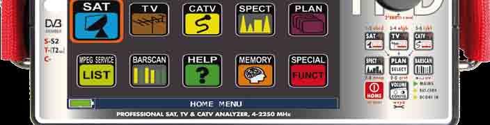
4 HOME and NAVIGATION HOME Screen Press the HOME key to go to the home screen then rotate the wheel to navigate in the SAT, TV or CATV icons and press the wheel to select the measurement mode required. Press the HOME key at any time to return to the home screen NAVIGATION Use the touch screen and the wheel to navigate across the screen and to change values DISPLAY ZONES Tuning parameters Live picture Measurements Channel info Transport Stream info Context sensitive menu CHANGING Values Navigate to an item then select, Rotate the wheel to change the value of the item Drop-down menus Navigate in a drop-down menu then keep pressed Rotate the wheel to highlight a value and press to select NUMERICAL KEYBOARD Navigate in a numerical value and keep pressed 4 Press the key with the value required to insert the numbers


5 Volume & Configuration Volume selection is immediately active, press ENTER for the Display configuration and other important settings VIDEO IN and VIDEO OUT Video out: Select ON to send the pictures of the TFT monitor to a TV or Video projector. Video will be available on an external display. Video In: Select EXT to visualize an external video source. NOTE: ASI IN : not available in this model. BATTERY SAVING and TIMER OFF Settings for battery save mode. Choose BATTERY SAVING from the volume screen. In ON mode, if no key is pressed, after 30 seconds, the display brightness is reduced and after 5 minutes the meter automatically turns off. press any key to temporarily reset the battery save mode. navigate in CONFIGURATION MENU then METER in the volume screen and set the TIMER OFF value required. The meter will turn off after 5 or 10 minutes of inactivity. Press any key to interrupt the automatic turn-off. 5
6 6 - NOTES -
 Mode Navigate in TV and then DISCOVERY and set the identification mode: - TERR ONLY - TERR & CABLE Navigate in CATV")

7 DISCOVERY Identifies the modulation of a tuned TV channel in the TV master PLAN Navigate in the CONFIGURATION MENU in the VOLUME window TV Mode CATV (cable) Mode Navigate in TV and then DISCOVERY and set the identification mode: - TERR ONLY - TERR & CABLE Navigate in CATV and then DISCOVERY and set the identification mode: - CABLE ONLY - TERR & CABLE NOTES: - DISCOVERY mode is active only if the antenna cable is connected to the instrument - DISCOVERY mode is not active if you use a manual or automatic memory plan (Manual Memory or Automemory) 7
 and the noise level, estimated in the band between the colored subcarrier and the audio")
8 C/N TYPE Set the measurement mode of the carrier noise ratio C/N (in band-out band) Navigate in configuration menu from the volume screen Navigate in TV then C/N TYPE C/N measurement mode IN BAND the signal/noise ratio is measured between the signal level of the video carrier (signal/carrier, red marker) and the noise level, estimated in the band between the colored subcarrier and the audio carrier (white marker) C/N measurement mode outside the band The signal/noise ratio is measured between the signal level of the video carrier (signal/carrier, red marker) and the noise level estimated in the guard band ( MHz from the video carrier, white marker) 8


9 SAT SAT Analyze Satellite Television Signals SWITCH TO SAT MODE t h en o r SAT p r e s SAT channel plan screen "Satellite information (mux data) is provided in cooperation with LyngSat DIGITAL SAT MEASUREMENT DISPLAYS DVB-S AND DVB-S2 Main measurements & live picture Navigate in the picture to zoom, touch again to return to the measurement 8PSK Constellation Navigate in ZOOM and select the constellation square window to enlarge Press to cycle through SAT measurement screens RELATED FUNCTIONS SAT Spectrum Analyzer SAT Channel Plan Selection MPEG SERVICE MPEG service list Identifies the tuning parameters of a digital signal 9
 t h en o r TV p r e s")


10 TV TV Analyze Terrestrial Television & Radio Signals switch to TV mode (All channels received at the Antenna) t h en o r TV p r e s tv channel paln ANALOG RADIO MEASUREMENT DISPLAY Navigate in CHAN & select FMH or FML, navigate in MODULAT & select FM Radio, navigate in FREQ and select the frequency required. ANALOG TV MEASUREMENT DISPLAY navigate in CHAN and select the channel required. If it is analog you will see the following displays: Level measurement and picture other measurements 10 press to cycle through the TV measurements
 Navigate in CHAN and select the channel required.")

 press to cycle")


11 DIGITAL TV MEASUREMENT DISPLAYS DVB-T & DVB-T2 (opt.) Navigate in CHAN and select the channel required. If it is digital you will see the following displays: Main measurement and picture DVB-T2 constellation (opt.) Navigate in ZOOM and select the constellation square window to enlarge Impulse response screen (echo) press to cycle through TV measurement screens N.B.: DVB-T2 measurements are available with the DVB-T/T2/C option. Navigate in TYPE select the echo visualization mode: DISTANCe or TIME Microechoes visualization Touch MENU on the ECHOES screen Touch TYPE and select µechoes MicroEchoes visualization 11
, in other words a national television broadcaster has the same frequency/channel all over")
, coming from the different distances in which the transmitters are situated, becomes")


12 ECHO & MICROECHO MEASUREMENT in SFN TV NETWORKS HOW TO REDUCE INTERFERENCES IN SFN NET WORKS Rover Instruments reminds you that the analogue TV switch off is well underway in Europe. Some countries, such as Spain and Italy, have decided to install digital TV SFN (Single Frequency Networks), in other words a national television broadcaster has the same frequency/channel all over the country. This provides a fantastic opportunity, but also means that in areas between two cells, it is possible to receive the same signals from more than one transmitter. If the SFN network has been designed well, the SFN signals slight propagation delay (which we will call echoes ), coming from the different distances in which the transmitters are situated, becomes absorbed in the invaluable GUARD INTERVAL function, present in the DVB-T & T2 (COFDM) modulation and consequently there will not be any reception problems. In any case, experience over the last few years has shown us that reality is different to theory, especially when there are many local television networks that could generate many interferences. You could therefore encounter the unpleasant experience of receiving a signal with good power, but that cannot show any pictures and not be able to establish the cause of the fault. In this case it is indispensible to measure the IMPULSE RESPONSE in real time, to measure the echo s delay or advance compared to the main signal. When changing direction and position of the antenna it is possible to optimize reception intuitively, by maximising the power of the main signal and minimize the power of interference echoes, also at the expense of the channel power. Once again Rover Instruments is the first company to supply meters for TV installers, that can measure up to 16 ECHOES and PRE-ECHOES in real time. ROVER meters allow you to see ECHOES, measure the power and the delay in us and the distance of the interfering broadcaster in Km. There are currently very few meters that allow you to measure ECHOES and PRE-ECHOES, in real time and at a distance of up to 75 Km, higher than the maximum amplitude possible with the GUARD INTERVAL and above all that can highlight, using the green mask, the useful reception area, in other words within the guard interval. The width of the GUARD INTERVAL varies according to the modulation parameters: consult the table below to find the width of the GUARD INTERVAL and all the possible DVB-T configurations. Fig. 1: OPTIMUM RECEPTION:* no ECHO present either outside or inside the guard interval mask (green area) N.B.* Valid examples for a DVB-T OFDM 8k signal with an 8 MHz Bandwidth and a 1/8 Guard Interval, this data is shown on ROVER meters to the right of the Constellation, see below Fig. 4. Fig. 2: GOOD RECEPTION:* 2 ECHOES present, but within the guard interval mask (green area) coming from a distance of: 1st echo: 15 Km, the same as a 50 µs delay 2nd echo: 25 Km, the same as a 83 µs delay DVB-T carriers (2K DVB-T) Fig. 3: MARGINAL RECEPTION (or IMPOSSIBLE):* 2 ECHOES present outside the guard interval mask (green area), coming from a distance of: 1st echo: 40 Km, the same as a 133 µs delay 2nd echo: 45 Km, the same as a 150 µs delay TEMPORAL GUARD INTERVAL WIDTH (already automatically highlighted by the GREEN mask) GUARD INTERVAL 1/4 1/8 1/16 1/32 max time (microsecondi) max distance (Km) DVB-T carriers (8K DVB-T) Fig. 4: DVB-T-64Q CONSTELLATION: The table to the right shows all the received modulation parameters GUARD INTERVAL 1/4 1/8 1/16 1/32 max time (microsecondi) max distance (Km) RELATED FUNCTIONS TV SPECT TV Channel Plan Selection BARSCAN Barscan MPEG SERVICE MPEG service list Finds the tuning parameters of a digital signal


13 CATV CATV Analyze Cable Television Signals SWITCH TO CATV MODE (All antenna and S band channels) t h en o r CATV p r e s CATV channel plan screen DIGITAL CATV DVB-C measurement display Main measurements & live picture Navigate in the the picture to enlarge press again to return to the measurements 64 QAM constellation Navigate in ZOOM and select the constellation square to enlarge Press to cycle through CATV measurement screens RELATED FUNCTIONS CATV SPECT CATV Channel Plan Selection Barscan MPEG SERVICE MPEG service list Finds the tuning parameters of a digital signal 13

14 SPECT SPECT Spectrum Analyzer SWITCH TO SPECT MODE Or SPECT SPECTRUM ANALYZER SCREENS Navigate in SPAN to modify the value or directly select the active span value or fast spectrum Press the spectrum key again to activate the MAX HOLD function Rotate to navigate enter to confirm Fast spectrum with peak memory Max H press to cycle through spectrum analyzer screens RELATED FUNCTIONS Finds the tuning parameters of a digital signal Navigate in MENU to visualize the additional spectrum functions 14


 ANALOG CHANNELS DIGITAL CHANNELS Touch pilot 1 and pilot 2 to select the two channels to be")
15 MPEG SERVICE LIST (MPEG service) show and select available mpeg ts services MPEG SERVICE Or navigate in Vpid - Apid in the measurement windows TV-CATV-SAT and press ENTER twice Rotate to navigate Navigate in Vpid - Apid & press enter to return to the measurements or press the SAT/TV/CATV measurement key mpeg service list BARSCAN BARSCAN LEVEL GRAPH Check all channels level/power In the TV standard canalization the meter displays the level/power of all channels. In AUTOMEMORY or MANUMEMORY PLAN the meter displays the memorized channels and distinguishes Analog and Digital signals using 2 different colours Or BARSCAN Touch menu to choose the bargraph mode: level or tilt Barscan (graphic LEVEL) ANALOG CHANNELS DIGITAL CHANNELS Touch pilot 1 and pilot 2 to select the two channels to be used for the tilt measurement (level difference) N.B. Function available only in TV or CATV mode 15


.")


16 HELP inspect the parameters of an unknown signal The help function identifies the tuning parameters of a digital tv or sat signal. HOW TO USE THE HELP FUNCTION Spectrum mode move the mrk. Fr to the center of a digital carrier o R In measurement mode when the lock icon is open (the signal is not locked) Navigate in HELP on the main menu Press to start the search The help function will try to identify the tuning parameters of the selected digital carrier At the end of the search (the word Found will be shown in the 3 boxes) the meter automatically shows the measurement display and the picture of the selected carrier (if available). SPECIAL SPECIAL FUNCTIONS SPECIAL N.B.: the special functions depend on the active operating mode: TV SAT or CATV TV: Buzzer & Noise Margin graph navigate in: BUZZ&NOIS.MARG.GR Buzzer & Graphic of the progress of the noise NOISE MARGIN of the tuned channel according to time. high tones = the BEST Noise Margin level deep tones = the WORST noise margin level Noise Marg = real time noise margin Max n.marg = maximum stored noise margin 16 N.B.: The function is also available in CATV and SAT mode


 and the type")
17 SAT: SAT SCR Navigate in SAT SCR navigate in LNB TYPE nd choose the LNB/MULTISWITCH model navigate in SCR USER, and choose the user number to test (USER 1-8) Press SPECT to display the spectrum or MEAS to start measuring or navigate in SCR CABLE TEST to perform in spectrum mode the SCR LNB/ MULTISWITCH 8 frequencies check (USER 1-8). SAT: SAT Finder navigate in SAT FINDER To change the displayed transponders manually, touch stop and select the wanted tp/ts. Touch start search to start. If the chosen satellite is found the buzzer will start, if this does not happen, continue looking for the right satellite. Optimize the dish alignment and skew to obtain the maximum NsMAR value (noise margin). N.B.: For a proper use of the sat finder function, verify the tuning parameters for all three transponders (frequency, polarity, band, and symbol rate) and the type of lnb you are using (universal or quatro) Go to the site for more information 17


18 MEMORY MEMORY channel Plans and Log Files MEMORY AUTOMEMORY (TV) To automatically store all the existing channels in a city or building navigate in AUTOMEMORY TV and press the wheel Set the desired parameters: Navigate in to FILE N and select the destination file AUTO where the search must be saved. Navigate in LEVEL and set the minimum level threshold of the analog channels searched. Navigate in POWER and set the minimum power level of the digital channels searched. Navigate in DISCOVERY and set the channel search mode. - TERR ONLY (terrestrial only) - TERR & CABLE (terrestrial & cable) Navigate in START SAVE to create a new channel plan and to activate the search. NOTE: If the words START OVERWRITE appear, the selected file will be overwritten. wait a few mins, the meter indicates the recorded ANALOG & DIGITAL CHannels 18 upon automemory completion the new plan is automatically selected


 for example, create or adjust the memory plans, print them or export")
19 LOGGER SAVE Touch SAVE DATALOGGER and set the parameters required. Touch START SAVE to create a new log file DATA LOGGER run N.B.: if the MANU plan has mixed TV and SAT programs, the STOP&GO function will assist when running a LOGGER asking to move the cable lead from a TV to a SAT signal source or vice-versa. LOGGER RECALL Touch RECALL DATALOGGER and Set the LOG file parameters. Touch RECALL? to see them Browse through measurements saved in the log file Rotate to Navigate S.m.A.R.T. PROGRAm The S.M.A.r.T. program is required to interface the meter with the PC. using the Pro version of the S.M.A.r.T. program, is it possible to control the internal memories (MAnu file, automemory, logger) for example, create or adjust the memory plans, print them or export them in excel. for more information read the page relevant to the S.M.A.r.T. Program in this user s guide or go to the site. EXCEL is a trade mark of Microsoft corporation. 19

20 SERVICE and SUPPORT WEB registration and SoFTWArE UPGRADES FW-SW UPGRADE ROVER offers you the possibility of carrying out FREE SOFTWARE and MEMORY PLAN (file mem) UPGRADES on your Meters, by simply REGISTERING your data in the Download Area (Update SW); Once you have registered, you can download the ROVER S.M.A.R.T. INTERFACE PROGRAM, which is necessary for the installation of Software and Memory Plan upgrades (file mem); ROVER also invites you to register to receive our NEWSLETTER service, which allows you to receive by and FREE OF CHARGE information regarding: New Software upgrades, Technical Communications, Training Courses, Technical Articles, Product News, Invitations to exhibitions and roadshows and much more besides. DOWNLOAD AREA REGISTRATION (Update SW) If you have not already registered, click on the words Update SW in the menu above, to your right; Click on Register now at the top of the page to access the Download Area; Fill in the electronic form with all your personal information and the Username of your choice; After you have completed the form, confirm by pressing the black Send key at the bottom of the page; Once sent, a page will be shown with a summary of your Registration Data, where you can Modify your data, Print it or Directly Access the Download Area; You will also receive an message, reminding you of your chosen User Id and the Password assigned by ROVER. Keep it in a safe place for future access to the Download Area and so that you can download new Software upgrades. ROVER S.M.A.R.T. INTERFACE PROGRAM Once you have REGISTERED in the Download Area, you must identify and download the correct ROVER S.M.A.R.T. Interface Program, required to connect your ROVER Meter to your PC and to upgrade the Software and Memory Plans (file mem). There are 2 versions of the ROVER S.M.A.R.T. Interface Program: One is for FAST Meters and is called the S.M.A.R.T. FAST, this is valid ONLY for Meters in the FAST Series; The other Program is called S.M.A.R.T. and is for ALL the other ROVER Meters. Both versions are available in 2 configurations: The STANDARD Version allows you to upgrade the Software of your Meter; The PRO Version, not only allows you to upgrade your Software, but also to upgrade Memory Plans (file mem) and to manage the internal memory (MANU FILE, AUTOMEMORY, LOGGER etc.): for example to create Memory Plans, print them or export them in EXCEL. The ROVER S.M.A.R.T. Interface Program automatically activates using the PRO Version. 30 days after it has been installed on your PC it automatically passes to the STANDARD Version. To active the ROVER S.M.A.R.T. Interface Program PRO version permanently, contact the ROVER After Sales and Service Department: tel and ask for an activation LICENCE. 20
21 procedure To upgrade SoFTWArE SOFTWARE UPGRADES: Once you have identified and download the correct ROVER S.M.A.R.T. Interface Program, install it on your PC in order to upgrade your Meter s Software. In the Download Area, identify the exact NAME/MODEL of your Meter and click on the corresponding picture. Then click on the corresponding FW Upgrade - version x.xx file and download it on your PC. If you want to see more detailed information about the Software upgrade contents, click on the +INFO+ icon. SOFTWARE UPGRADE PROCEDURE: WARNING! Before carrying out your meter s Software upgrades, we suggest you close all the applications that are active on your computer: messages, internet, management programs, etc; Do not use, turn off or disconnect the Meter from the mains during the upgrade; If the graphic bar showing the upgrade advancement blocks, do not interrupt the procedure because thee Software download is still taking place event if the PC monitor does not correctly show the advancement in sequence; If the upgrade interrupts or does not conclude, we suggest you check connections and repeat the procedure from the beginning. PROCEDURE: 1. Connect your Meter to the mains and turn it on; 2. Wait for the Start Up phase to finish correctly; 3. Connect the USB cable, FIRST to the Meter and THEN to the PC; 4. Start up the ROVER S.M.A.R.T. Interface Program; 5. In the ROVER S.M.A.R.T. Interface Program window, click on Instrument followed by Upgrade Firmware ; 6. In the Open window, select the Software upgrade File (.rvr) downloaded from the Download Area; 7. Click on Open and confirm the selection; 8. The Software upgrade procedure will automatically start up; 9. If this does not happen, the Upgrade Firmware window will open, select the exact model of your Meter and click on Upgrade to carry out the Upgrade manually. 10. Wait a few minutes, the ROVER S.M.A.R.T. Interface Program will load the new firmward in your Meter; 11. Once the download has been completed, the following message will appear: Power on the meter to activate FW **PROGRAM SUCCESFUL** and, if available, the summary of the Meter settings; 12. If the Meter did not automatically turn off, turn it back on again and check, in the Start-up or Self-Test window (METER INFO - INFO ABOUT), the Software version number. WARNING! If the operation, described in this paragraph continues to fail, contact the ROVER After Sales and Service Department: Telephone: wecare@roverinstruments.com It is possible to download the Software Upgrade Procedure directly from the ROVER website at the following address: Please refer to the section Technical Support SW Upgrade. 21
22 MEMorY plan upgrades procedure (file MEM) WARNING: To load the Memory Plans (file mem) you must install the PRO version of the ROVER S.M.A.R.T. Interface Program on your PC. Once you have accessed the Download Area, identify the exact MODEL/NAME of your Meter and click on the corresponding picture; IF AVAILABLE, click on the relative Memory File: Plans and satellites... (.mem) and download it on your PC. PROCEDURE: 1. Connect your Meter to the mains and turn it on; 2. Wait for the Start Up phase to finish correctly; 3. Connect the USB cable, FIRST to the Meter and THEN to the PC; 4. Make sure that you have installed the PRO Version and start up the ROVER S.M.A.R.T. Interface Program; 5. In the ROVER S.M.A.R.T. Interface Program window, click on Instrument followed by Connect Instrument ; 6. Click on Tools, then Mem e and then Open Mem ; 7. In the Open window, select the Memory File (.mem) downloaded from the Download Area; 8. Click on Open and confirm the selection; 9. Click on Tools, then Mem and then Write Mem to Instruments ; 10. The following message will appear: WARNING: This operation will delete all the previous plans stored in the meter ; 11. Click on OK and confirm to start the Upgrade; 12. Wait a few minutes, the ROVER S.M.A.R.T. Interface Program will load the new Memory Plans (file mem) in your Meter. 13. Once the download has been completed, the Following message will appear: Plan Memory downloaded succesfully!. WARNING! If the operation described above continues to fail, contact ROVER Instruments using the following numbers: Telephone: Mail: wecare@roverinstruments.com It is possible to download the Memory Plan Upgrade Procedure (file mem) directly from the Rover website: Please refer to the Technical Service and support area - Meter SW upgrades. 22


23 LI-ION polimer BATTEriES IMPORTANT: ALWAYS TURN THE INSTRUMENT OFF BEFORE CONNECTING THE BATTERY CHARGER. DO NOT LEAVE THE BATTERIES DISCHARGED FOR LONG PERIODS. ALWAYS CHARGE THE BATTERIES AT NIGHT FOR AT LEAST 7 HOURS, EVEN IF THEY ARE NOT COMPLETELY DISCHARGED. USEFUL INFORMATION: 1. The batteries supplied are high quality and tested individually, to guarantee an autonomy of between: 6 hours min. and 10 hours max. depending on the following conditions: the LNB power consumption: Single, Dual or Quadruple, the external temperature: with temperatures of less than 10 C, 20% of the capacity is lost, the age of the batteries: a 10% loss in efficiency each year, Remember that the TIMER OFF function, that automatically turns off the meter after 5 minutes of inactivity saves up to 30%. 2. The battery indicator has a tolerance (like all battery powered electronic devices) according to the following factors: - the battery s charging percentage - external temperatures - battery wear and tear +/ 2%. ICONS SHOWING THE BATTERY CHARGE STATUS: WARNINGS RECHARGEABLE BATTERY This device contains a built-in Li-PO (Lithium polimer) battery that can be recharged many times. The battery contains chemicals that might wear with time even if not used. Please dispose of batteries properly. Do not take the battery pack apart or expose it to extreme temperatures (over 50 C). If the device has been exposed to very low or high temperatures let it rest at room temperature before use. RECHARGING THE BATTERY The Battery must be recharged at room temperature (about 20 C) with the device turned off. To avoid premature failure of the battery never leave the device with an empty battery for prolonged periods. 23

24 BATTErY TEST & BATTErY regeneration THiS procedure EXpLAiNS HoW To regenerate/check Your BATTEriES AND CALiBrATE THE BATTErY CHArGE indicator Useful advice: CHArGE THE BATTEriES EVErY NiGHT AFTEr use, EVEN if THEY ArE NoT CoMpLETELY DiSCHArGED. Always use the battery save & timer off functions to increase your meter s autonomy. THE MAXiMuM CApACiTY of THE BATTEriES AND BATTErY CHArGE indicator S ACCurACY improves BY up To 20% if You CArrY out MANY BATTErY TEST CYCLES. Do NoT replace THE BATTEriES: FirST CArrY out 3 To 5 BATTErY TEST CYCLES until You recover THE MAXiMuM CApACiT Y of THE BATTEriES. BATTErY TEST instructions & procedure 1. Before carrying out the test connect the meter to the battery charger (12v 3a). Turn on the meter press the volume key and select configuration menu (fig. 1), Select the word meter (fig. 2), Select battery test and select on (fig. 2), Press enter to confirm. Carefully read the various screens, pressing enter in succession. in the last instructions window, select start and press enter to start the test. Warning: the procedure will be cancelled if you select exit on any screen. fig. 2* fig. 1* fig. 3* Important advice Do not connect any type of load to the f input connector (lnb, tv head-end, amplifiers, etc.). Extract the conditional access module (cam), if it is present in your meter. 2. The battery test takes approx. 2/4 Hours (to carry out discharging and measurement of the battery autonomy), during this time the meter must not be used. At the end of the test the meter will turn off automatically. in order to make sure that the test has been carried out correctly, all the meter s commands are blocked except for the reset function, which remains active so that the meter can be turned off if necessary. 3. At the batteries will be completely discharged at the end of the test. To check the battery test results, enter once again into meter or meter setup in the configuration menu and read the results: For example ( fig. 3 ): 396 Indicates the minutes necessary to completely charge the batteries 100 provides the battery status in percentage form 675 Indicates the battery autonomy in minutes. Important notes if the test is interrupted using reset, the battery charge indicator may provide incorrect indications, therefore charge the batteries again (7 hours minimum) and repeat the battery test procedure. *The displays shown in this guide may change according to the model and are subject to change without notice. if you connect your meter, using the s.m.a.r.t. pro program, from the usb port to the pc, you can download the screens shown above. 24
25 Power Supply (mains) and Battery Charge (chrg) LED status INSTRUMENT CONNECTED TO THE MAINS POWER SUPPLY LED MAINS LED BATT CHRG NOTES OFF NO OFF OFF Batteries sufficiently charged ON NO OFF OFF Battery operation OFF NO OFF Flashing 2 SECONDS OFF 0.5 SECONDS ON The meter does not turn on. Recharge the batteries. OFF YES ON Flashing 0.5 SECONDS OFF 0.5 SECONDS ON Abnormal battery temperature. The recharge cycle has been suspended temporarily and will automatically reset. OFF YES ON ON Batteries in fast charge OFF YES ON OFF Battery charge completed OFF WITH A POWER SUPPLY NOT FROM ROVER Flashing 0.5 SECONDS OFF 0.5 SECONDS ON OFF The meter does not turn on. Check the mains power adapter turning ON NO or YES FLASHES 15 TIMES OFF The meter is being turned on ON NO or YES FLASHING SIMULTANEOUSLY 0.5 SECONDS OFF SECONDS ON The meter detects an error and turns off automatically. ON YES FLASHING ALTERNATIVELY 1 SECOND OFF - 1 SECOND ON BATTERY TEST being carried out. The meter charges and discharges the batteries AUTOMATICALLY 25
26 meter maintenance CLEANING THE METER Cleaning the meter from dust and dirt is easy and helps mantaining it in optimal work conditions through the years. The cleaning procedure is simple and quick and requires only minor attention. Never use chemical aggressive products (diluent) and/or abrasive or rough clothes which may damage plastics and displays. Always use a soft cloth, damped with a simple water and alcohol solution or a de-greasing not abrasive liquid soap. Keyboard and display should be gently cleaned. Rubbing the keyboard and/or the display(s) may seriously damage their functions. MAINTENANCE AND CARE OF THE METER This meter has been designed to withstand severe conditions of use. Even so, its life may be prolonged by respecting some simple and effective rules: The meter has not been designed to withstand high temperatures (over 60 C or 140 F). Those temperatures can be easily reached when the meter is left in a car, especially behind the windshield, or in the trunk. The LCD display and/or other details may easily be damaged by the extreme temperature. The internal battery may rapidly loose its efficiency if exposed to high or low temperatures. This will result in reduced autonomy of the meter when powered by internal battery. When recharging the internal battery, do allow a good air circulation around the meter and the adapter: do not cover it with clothes and do not recharge the battery when the meter is contained in its transport case The meter is not waterproof, even if it is protected against incidental water drops. In case of contact with water, electronic circuits may be damaged, allow the meter to dry thoroughly before trying to turn it on. Do not use hairdryer or other strong heating sources, but just leave the meter in quiet air. If possible, contact Rover Laboratories S.p.A. Technical Assistance. 26
27 SERVICE NOTES and GUARANTEE REGULATIONS (CEE and EXTrA CEE) ROVER Laboratories. S.p.A. has a standard guarante period of 12 months. This is extended to 24 months for countries within the European Community, and in any case, in accordance with the laws and/or possible regulations applied in your country. GUARANTEE REGULATIONS: 1. IMPORTANT: the guarantee is valid only upon the presentation of invoice or receipt to ROVER Laboratories S.p.A. The purchase date must be clearly indicated on the invoice/receipt. 2. The guarantee covers the replacement free of charge of parts only, when malfunctioning is solely due to manufacturing faults. The faults must be indentified and defined by ROVER personnel only. 3. The guarantee is void if: a. the equipment is tampered with or repaired by non-authorized personnel b. damage is found, caused by the incorrect use of the equipment, without following the advice explained in the User s Guide accompanying the equipment. c. damage is found caused by the use of the equipment in unsuitable working environments. 4. The following parts are not covered by the guarantee: a. Parts subject to wear, such as aesthetic ones, keyboard, plastic chassis, etc. b. Batteries. c. Bags and carrying cases, including shoulder straps. 5. The equipment can not be replaced and the guarantee is extended after the repair of a fault. SERVICE NOTES AND PROCEDURES: 6. The equipment can only be repaired by the manufacturer or by an authorized ROVER Laboratories service center: a. Before returning the meter for repair, always contact the distributor where you purchased the unit or an authorized service center if present in your area to obtain the return procedure for your analyzer. If no authorised ROVER service centers are available in your area, please contact ROVER Laboratories S.p.A. directly at the following telephone/fax numbers and/or address: Telephone number Fax number wecare@roverinstruments.com b. Important: please take note that non-authorised returns for repair to ROVER Laboratories S.p.A. will be rejected. c. When returning the meter, always send it with the following documentation attached: the fully-compiled FAULT IDENTIFICATION FORM transport document the eventual request for an estimate of repair costs d. Please note that the request for an estimate of repair costs must be submitted upon return of the analyzer with a written note. If the repair cost estimate is not accepted, ROVER Laboratories reserves the right to charge the customer for the estimate costs analysis. 27

28 7. Risks and costs for transport to ROVER Laboratories S.p.A. must be sustained by the buyer. After repair, if the equipment is under guarantee, ROVER Laboratories S.p.A. will pay for the transport returning the goods to the customer. If the instrument is not under guarantee, after repair, the equipment will be returned by courier service with the amount to be paid by the customer shown on the invoice. 8. The guarantee does not cover compensation for direct or indirect damages of any kind to people or goods caused by the use of the equipment and/or compensation caused by the suspension of use due to eventual repairs. 9. ROVER Laboratories. S.p.A. is not responsible for eventual tampering and/or modifications that may cause the goods to no longer adhere to the European CE regulations, especially regarding EMC and safety. 10. ROVER Laboratories instruments is recognised and is fully compliant with DVB regulations and specifications (ETS /94) and is consequently marked with the DVB logo. DISPOSAL of ELECTRONIC EQUIPmENT Disposal of electric / electronic equipment (applicable in all CEE countries and whereever separate waste collection system is applied). This symbol on the packaging indicates that the product should not be considered as domestic waste. The product, at the moment of disposal, should be brought to a waste collection point with the proper facilities to manage electrical/electronic appliances. Electric/electronical appliances, if not disposed of correctly, may have negative consequences on your health and enivironment. Furthermore, a proper recycling procedure helps mantaining natural resources. To have more information about proper disposal of this product, please refer to your local waste management offices or the shop where this product was bought. 28
29 FAULT IDENTIFICATION FORm To: ROVER INSTRUMENTS SERVICE DEPARTMENT Fax: Skype: wecare.roverinstruments Subject: FAULT Identification Form PLEASE FILL IN ALL AREAS. Date:... CUSTOMER INFORMATION. Name & Surname:... Company:... Contact name:... Address:... City:...ZIP code:... Tel.:... Mobile:... Fax: Skype:... METER INFORMATION. Meter Model:... Purchase date:...invoice number:... Bought from:... Firmware version (FW):... Hardware version (HW):... Serial number (S. NO):... NOTE: the information relevant to : model, serial number, firmware/hardware version are available on the initial display after switch on (start up) or on the meter s information display in the configuration menu. In case the meter does not switch on, you may find the meter s serial number on the label placed on the rear of the meter. FAULT DESCRIPTION. Using few, but precise, words please describe here below (*) the fault found and forward to our Service Department for more instructions on how to proceed. If necessary provide pictures or loggers & saved screens using the SMART PC interface sortware (available on our website (*) add lines if more space is needed for your description. DO NOT RETURN THE meter WiTHouT OUR AuTHoriZATioN NuMBEr AND rover SHipMENT instructions otherwise THE meter WiLL BE REJECTED UPON ARRIVAL TO ROVER. To receive your authorization number call:
30 SUGGESTED VALUES This table shows the suggested measurements at a user s socket for the main digital modulations. DVB-T2 & GB COFDM 40 dbµv 50 dbµv PER MER 256 QAM 2/3 FEC MER 256 QAM 3/4 FEC MER 256 QAM 5/6 FEC 7 25 db 26,5 db 28,5 db 28 db 29,5 db 31,5 db 30
31 INDEX 2 Get to know your HD FLASH 4 Home and navigation 5 volume & configuration 9 SAT - SAT: analyze Satellite Television Signals 10 TV TV: analyze Terrestrial Television & Radio Signals 12 Echo & microecho measurements in sfn tv networks CATV 13 CATV: Analyze Cable Television Signals SPECT 14 SPECT: Spectrum Analyzer MPEG SERVICE 15 LIST: show and select available mpeg ts services BARSCAN 15 BARSCAN: Check all channels level/power 16 HELP: inspect the parameters of an unknown signal SPECIAL 16 Special functions MEMORY 18 MEMORY: channel plans and log files 19 S.M.A.R.T. program 20 Service & support web registration & sw upgrades 21 Procedure to upgrade software 22 MEMORY PLAN UPGRADES PROCEDURE 23 LI-ION POLIMER BATTERIES 23 WARNINGS 24 BATTERY TEST & BATTERY REGENERATION 25 power supply (mains) & battery charge (CHRG) LED status 26 METER MAINTENANCE 27 SERVICE notes & guarantee regulations 28 DISPOSAL of ELECTRONIC EQUIPMENT 29 Fault identification form 30 Suggested values 31
32 Customer Support skype only for call wecare.roverinstruments UG-HDFLASH-EN-V2,1 Designed in Europe, Assembled in Europe RO.VE.R. LABORATORIES S.p.A. Via Parini 2, Sirmione (BS) Italy tel fax product specification are subject to change without notice. All trademarks used are properties of their respective owners.
DUAL TOUCH: RESISTIVE & CAPACITIVE, RESISTANT to RAIN, DIRT & SCRATCHES 6.5 TOUCHSCREEN 16:9 TFT. Bars Scan TV = analog = digital See page 23
 DIGICUBE STC The only completely TOUCHSCREEN analyzer HD MEASUREMENTS SUGGESTED MEASUREMENT VALUES SUN & RAIN PROOF DUAL TOUCH: RESISTIVE & CAPACITIVE, RESISTANT to RAIN, DIRT & SCRATCHES 6.5 TOUCHSCREEN
TAB 700 & TAB 700 USER S GUIDE. TFT 16:10
 HD TAB 700 TAB 700 & TAB 700 HD Plus Plus 700 TAB & TFT 16:10 USER S GUIDE www.roverinstruments.com GET TO KNOW YOUR TAB 700 FRONT PANEL NB: The MENU (functions and Graphics) an be change without advise.
Horizon HD-STM. Combo Signal Analyzer TEST REPORT
 TEST REPORT Combo Signal Analyzer Horizon HD-STM can be used intuitively, manual is not needed perfect workmanship optimized for the day-to-day work of an installer gives all the "Must-Have" informations
Easy-to-use : setup, frequency maps, recorded data can be saved or downloaded from a USB memory stick.
 TV picture : the high quality LCD screen is used to provide TV pictures, SD or HD TV programs, for terrestrial, cable and satellite. Easy-to-use : setup, frequency maps, recorded data can be saved or downloaded
S7000L. TV & Satellite Analyzer. All IN ONE. Satellite & Terrestrial. Key Features. Model Guide
 S7000 TV & Satellite Analyzer Key Features All standards in one: QAM(J.83A/B/C), 8VSB, DVB-T/H/T2, DVB-S/ S2 Digital/Analog TV and Satellite TV analysis MPEG2 Transport stream analyzer and monitoring via
ROVER LABORATORIES. M a d e to Measure 2015 INSTRUMENTS CATALOGUE. INSTRUMENTS DIVISION: SAT TV CATV OPTIC IP-TV Measurement Instruments
 2015 INSTRUMENTS CATALOGUE INSTRUMENTS DIVISION: SAT TV CATV OPTIC IP-TV Measurement Instruments ROVER LABORATORIES V.1 20-1-15 M a d e to Measure ROVER LABORATORIES S.p.A. Via Parini 2, 25019 Sirmione
All the functions you need in your hand
 All the functions you need in your hand Rely on H30FLEX for installation and troubleshooting. Robust, light-weight and extremely easy to use. Carry out installation, maintenance and troubleshooting tasks
BTPRO-7000 BTPRO-7000
 BTPRO-7000 Instruction Manual BTPRO-7000 Hardware Version 2 TFT 16:9 www.blondertongue.com 2 NOTES INDEX 4 Get to know your BTPRO-7000 6 Home and navigation 10 Volume & configuration SPECT 13 Screen Shot
HD-CM HORIZON DIGITAL CABLE METER
 HD-CM OFF! Max RF i/p = +17dBm 75Ω Max AC/DC i/p = 120Vrms MENU INPUT ON HORIZON DIGITAL CABLE METER Horizon Global Electronics Ltd. Unit 3, West Side Flex Meadow Harlow, Essex CM19 5SR Phone: +44(0) 1279
PROMAX NEWSLETTER Nº 22
 PROMAX NEWSLETTER Nº 22 TV EXPLORER HD series: H.264 / MPEG-4 AVC picture CV-100: Optical LNB adapter for TV EXPLORER MO-370: ISDB-T/T B modulator DIGITAL To TV: for Broadcast and TV Distribution PROMAX-27:
SEFRAM 7870 series The feeling of a new way of measurement
 SEFRAM 7870 series The feeling of a new way of measurement 2 New aluminium housing with excellent robustness 10 inch panoramic touch screen HD TV decoding for all standards High brightness which makes
HD4112 Quad HDMI MPEG2 HD DVBT Encoder Modulator U S E R M A N U A L
 HD4112 Quad HDMI MPEG2 HD DVBT Encoder Modulator U S E R M A N U A L HD4112 Manual Rev 1 Contents 1. GENERAL 1.1 Description 1.2 Specifications 2. INSTALLATION 2.1 What s in the Box 2.2 Connection 2.2.1
STM 17 HD. DVB-S2+T2/C Compact Meter. User Manual. Ref R13. CAHORS Digital CS Cahors Cedex 9 FRANCE.
 STM 17 HD DVB-S2+T2/C Compact Meter User Manual Ref 0145131R13 DVB COMBO METER 1. Main Features... 2 2. Buttons and Indicators... 3 3. How to measure... 4 4. Home menu... 5 5. Satellite... 5 5.1 Satellite
REVOLUTIONISING THE MARKET. AGAIN
 REVOLUTIONISING THE MARKET. AGAIN ACTUAL SIZE - 7 SCREEN (APPROX. 155 x 93 mm) The largest and brightest display HD RANGER+ 7 display is the brightest and largest used in any similar meter with excellent
PCM-1210 DVB COMBO METER User`s Manual
 PCM-1210 DVB COMBO METER User`s Manual 1. Main Features... 1 2. Buttons and Indicators... 2 3. How to measure... 3 4. Home menu... 4 5. Satellite... 4 5.1 Satellite Measure... 4 5.2 LNB Setting... 5 5.3
Digital Terrestrial Alignment & Installation Meter
 Digital Terrestrial Alignment & Installation Meter Instruction Booklet Version 3 - February 2005 www.horizonhge.com Thank you for choosing our latest and most innovative terrestrial meter. It has been
CompactMax-2 DVB-S/S2 TO DVB-T2 TRANSMODULATOR - 0 MI2100 -
 CompactMax-2 DVB-S/S2 TO DVB-T2 TRANSMODULATOR - 0 MI2100 - SAFETY NOTES Read the user s manual before using the equipment, mainly "SAFETY RULES" paragraph. The symbol on the equipment means "SEE USER
Refs , , Instruction Manual. Digital processing handheld DVB meter / Analyzer.
 Refs. 593301, 593302, 593303. 593304 EN Digital processing handheld DVB meter / Analyzer Instruction Manual www.televes.com Index EN General specifications... 4 Technical specifications... 4 Product Operation...
Owner s Manual. Sat-Meter MSK 15. Order No.:
 Owner s Manual Sat-Meter MSK 15 Order No.: 217 100 13 Thank you for choosing our latest and most innovative satellite meter. It has been designed and manufactured to a very high standard and offers a UNIQUE
SM-10 SAT Level Meter User s Manual
 SM-10 SAT Level Meter User s Manual DAGATRONICS CORPORATION 263-1 DUCKIDONG, ILSAN, KOYANG, KYUNGKIDO, KOREA TEL: +82-31-916-8005 FAX: +82-31-916-8080 Email: dagatron@dagatron.com Website: www.dagatron.com
ATLANTA ASF 2033HD+ DVB-S/S2 METER. User`s Manual
 ATLANTA ASF 2033HD+ DVB-S/S2 METER User`s Manual Buttons and Indicators... 2 How to measure... 3 Main menu... 4 LNB Setting... 4 Edit Satellite... 6 Spectrum Chart... 7 Constellation... 9 Angle Calculation...
ROVER LABORATORIES. M a d e to Measure 2014 INSTRUMENTS CATALOGUE. INSTRUMENTS DIVISION: SAT TV CATV OPTIC IP-TV Measurement Instruments
 2014 INSTRUMENTS CATALOGUE INSTRUMENTS DIVISION: SAT TV CATV OPTIC IP-TV Measurement Instruments ROVER LABORATORIES V.I2 21-10-14 M a d e to Measure v. H 17-9-14 ROVER LABORATORIES S.p.A. Via Parini 2,
Operating Manual. DVB-T Meter MFK 16
 Operating Manual DVB-T Meter MFK 16 Preface Dear customer, KATHREIN-Werke KG has made every effort to ensure the accuracy and completeness of this manual. However, no liability can be accepted for potential
AVE HOME FAGOR CVBS TO DVB-T ENCODER MODULATOR. Fagor Electr6nica
 AVE HOME CVBS TO DVB-T ENCODER MODULATOR FAGOR Fagor Electr6nica TABLE OF CONTENTS 1. SPECIFICATIONS... 12 1.1 Product Overview... 12 1.2 Appearance and Description... 12 1.3 Diagram... 13 1.4 Characteristics...
SZU OPERATING INSTRUCTIONS SAT NAVI
 SZU 21-00 O P ER ATI N G I N S T R U C T I O N S SAT NAVI Operation Instructions SZU 21-00 Safety Notes Turn off the receiver or any used power supply before installing, to avoid short-circuit. Installation
7880: A new family of TV Meters to meet the requirements of the XXI century!
 7880: A new family of TV Meters to meet the requirements of the XXI century! HEVC H.265 HEVC H.265 decoding Weights less than 3Kg DVB-C/C2 J83B DVB-T/T2 Lite Analogue TV DVB-S/S2, multistream 10 inch panoramic
Professional Radio TV, SAT & CATV Probe with IP Encap/Decap, ASI output, T.S. Analysis, HDSD SDI Output, Remote control with NMS & SNMP.
 EX AMINER Professional Radio TV, SAT & CATV Probe with IP Encap/Decap, ASI output, T.S. Analysis, HDSD SDI Output, Remote control with NMS & SNMP....Made to Measure... PROFESSIONAL SAT - TV - CATV PROBE
Test & Measurement Equipment
 Test & Measurement Equipment Rev: 03.2018 800-523-6049 www.blondertongue.com 2018 Blonder Tongue Laboratories, Inc. All Rights Reserved. Specifications subject to change without notice. All trademarks
PROMAX NEWSLETTER Nº 25. Ready to unveil it?
 PROMAX NEWSLETTER Nº 25 Ready to unveil it? HD RANGER Evolution? No. Revolution! PROMAX-37: DOCSIS / EuroDOCSIS 3.0 Analyser DVB-C2 now available for TV EXPLORER HD+ C-band spectrum analyser option for
TV AND SATELLITE ANALYSERS
 TV AND SATELLITE ANALYSERS HD Designed The new TV EXPLORER HD, HD+ and HD LE are the first field strength meters of their kind to incorporate all the measurements and functions necessary to ensure proper
SATFINDER 3 HD SLIM USER GUIDE
 SATFINDER 3 HD SLIM USER GUIDE INDEX General Safety..... 3 Key Features..... 4 Panel Keypads... 5 Accesory.. 6 Satellite Search...... 7 Spectrum..... 8 Cross Polarisation... 9 Packet TP Levels.... 9 Multi
RS232 Connection. Graphic LCD Screen. Power Button. Charger Adapter Input LNB Output. MagicFINDER Digital SatLock Operating Manual
 GENERAL FEATURES Easy-to-understand user-friendly menu and keypad. LNB short circuit protection. Display of Analog Signal Level, Digital Signal Quality with % and Bar, audible notification. Timer Lock,
Digital and analogue image demodulation. All measurements simultaneously. Professional spectrum. Full automatic operation. Autonomy of 4½ h.
 Digital and analogue image demodulation All measurements simultaneously Professional spectrum Full automatic operation Autonomy of 4½ h. Weight less than 2 kg. the TV Explorer: setting new standards The
MyM-3S Micro Master. Installation Guide. English. design for TV
 MyM-3S Micro Master Installation Guide design for TV 1 CONTENT 1. Introduction 2. Unpacking the unit 3. Connections and indications 4. IP settings 5. Menus and settings 5.1 Overview menu 5.2 Input settings
English CONTENTS 1. GUIDE OUTLINE THE MENU OSD INSTRUCTION TECHNICAL SPECIFICATION TROUBLE SHOOTING...
 USER S MANUAL English CONTENTS 1. GUIDE...2 1.1 IMPORTANT SAFETY INSTRUCTIONS...2 1.2 UNPACKING...2 1.3 PRODUCT OVERVIEW& ILLUSTRATION...3 1.4 INSTALLATION OF METER...4 2. OUTLINE...5 3. THE MENU OSD INSTRUCTION...6
HD RANGER+ Evolution? NO. Revolution!
 Evolution? NO. Revolution! The SIXTH GENERATION field meter FROM PROMAX lite ACTUAL SIZE - 7 SCREEN (APPROX. 155 x 93 mm) Revolutionising the market. Again The largest and brightest display HD RANGER+
DMOD1200MS. HDMI Modulator. User Manual PLEASE READ THE MANUAL COMPLETELY BEFORE USE V.17.09
 DMOD1200MS HDMI Modulator User Manual PLEASE READ THE MANUAL COMPLETELY BEFORE USE V.17.09 CONTENTS 1. INTRODUCTION 1.1. Product Description 1.2. Package Contents 1.3. Hardware Installation 1.4. Safety
new functions! Merogram Spectrogram We changed the way measurements are made! TERRESTRIAL CABLE SAT HDTV DVB-T/H DVB-C DVB-S/S2 measurements
 new functions! Merogram Spectrogram We changed the way measurements are made! HDTV SAT TERRESTRIAL CABLE measurements DVB-S/S2 DVB-T/H DVB-C One model for every need Select yours TV EXPLORER TV EXPLORER
Figure 1: V 713 CI plug-in card
 Version 04-2013A Device description Device description The delivery consists of the following parts: V 713 CI and X-DVB-CT2/PAL duo CI plug-in cards 2 connection cables with F connectors, 450 mm & F socket-f
Optical Receiver Manual. Transmitter OP-OR212JSE. Shenzhen Optostar Optoelectronics Co., Ltd (Version 2)
") Optical Receiver Manual Transmitter OP-OR212JSE Shenzhen Optostar Optoelectronics Co., Ltd 2016. 7(Version 2) 1. Summary OP-OR212JSE optical receiver is the latest 1GHz dual-way switch optical receiver.
Optical Receiver Manual Transmitter OP-OR212JSE Shenzhen Optostar Optoelectronics Co., Ltd 2016. 7(Version 2) 1. Summary OP-OR212JSE optical receiver is the latest 1GHz dual-way switch optical receiver.
SATFINDER4 INTRODUCTION USER GUIDE AND CERTIFICATE OF GUARANTEE
 SATFINDER4 INTRODUCTION USER GUIDE AND CERTIFICATE OF GUARANTEE CONTENTS : General Safety...... 3 Basic Properties.... 4 Front Panel Keys... 5 Back Panel Details 5 Charger Adapters.. 6 Utilization of Satfinder4......
R&S EFL240/R&S EFL340 Portable TV Test Receiver Professional installation of cable and satellite TV systems and antennas
 R&S EFL240/R&S EFL340 Portable TV Test Receiver Professional installation of cable and satellite TV systems and antennas Broadcasting Product Brochure 03.00 R&S EFL240/ R&S EFL340 Portable TV Test Receiver
We changed the way measurements are made! 99 Washington Street Melrose, MA Phone Toll Free
 99 Washington Street Melrose, MA 02176 Phone 781-665-1400 Toll Free 1-800-571-8431 Visit us at www.testequipmentdepot.com We changed the way measurements are made! One model for every need Select yours
USER MANUAL. 27 Full HD Widescreen LED Monitor L27ADS
 USER MANUAL 27 Full HD Widescreen LED Monitor L27ADS TABLE OF CONTENTS 1 Getting Started 2 Control Panel/ Back Panel 3 On Screen Display 4 Technical Specs 5 Care & Maintenance 6 Troubleshooting 7 Safety
HD-TM PLUS HORIZON DIGITAL TERRESTRIAL METER
 HD-TM PLUS OFF MENU INPUT ON HORIZON DIGITAL TERRESTRIAL METER Horizon Global Electronics Ltd. Unit 3, West Side Flex Meadow Harlow, Essex CM19 5SR Phone: +44(0) 1279 417005 Fax: +44(0) 1279 417025 Issue
Advanced HDTV System Analyzers
 H45 FIRST HANDHELD System Analyzer WITH DIGITAL PROCESSING Advance SERIES Advanced HDTV System Analyzers HDTV testing made simple - One single tool covers every testing need MPEG-4 FULL HD 1080P CABLE
R&S ETH Handheld TV Analyzer Portable DVB-T/H signal analysis up to 3.6/8 GHz
 R&S ETH Handheld TV Analyzer Portable DVB-T/H signal analysis up to 3.6/8 GHz Broadcast Product Brochure 02.00 R&S ETH Handheld TV Analyzer At a glance The R&S ETH handheld TV analyzer was specially designed
T3316 IP QAM Modulator User Manual
 T3316 IP QAM Modulator User Manual SW Version: 1.02 HW version: 0.70.0.0 Web NMS version: 1.02 Intended Audience About This Manual This user manual has been written to help people who have to use, to integrate
Quick installation and configuration guide STC
 Quick installation and configuration guide STC 200 REF. 4466 Contents 4 Introduction 4 General description 5 General use of the headend 6 Initial installation and configuration 6 Assembly, connection
Operation and Installation Guide
 Operation and Installation Guide HDS2800 Series Encoder Modulator High Definition (HD) Digital COFDM MPEG2 and H.264 Modulator with IP Multicast. 19 Rack Mount Wall Mount Revision 0.1 Firmware version
OPERATOR MANUAL OSD8865 DIGITAL TRIPLE VIDEO FIBER OPTIC RECEIVER
 OPERATOR MANUAL OSD8865 DIGITAL TRIPLE VIDEO FIBER OPTIC RECEIVER INDEX 1 1 TECHNICAL SUMMARY... 4 1.1 BRIEF DESCRIPTION... 4 1.1.1 OVERVIEW... 4 1.1.2 APPLICATIONS... 4 1.1.3 FEATURES AND BENEFITS...
News from Rohde&Schwarz Number 195 (2008/I)
") BROADCASTING TV analyzers 45120-2 48 R&S ETL TV Analyzer The all-purpose instrument for all major digital and analog TV standards Transmitter production, installation, and service require measuring equipment
BROADCASTING TV analyzers 45120-2 48 R&S ETL TV Analyzer The all-purpose instrument for all major digital and analog TV standards Transmitter production, installation, and service require measuring equipment
XCOM1002JE (8602JE) Optical Receiver Manual
 Optical Receiver Manual") XCOM1002JE (8602JE) Optical Receiver Manual - 2 - 1. Product Summary XCOM1002JE (8602JE) outdoor optical receiver is our latest 1GHz optical receiver. With wide range receiving optical power, high output
XCOM1002JE (8602JE) Optical Receiver Manual - 2 - 1. Product Summary XCOM1002JE (8602JE) outdoor optical receiver is our latest 1GHz optical receiver. With wide range receiving optical power, high output
Table of Contents. 1. Safety Use. 2. General Description. 3. Connection Diagram. 4. Operations and Management. 4.1 Display Status. 4.
 DTM-HD01 Thank you for buying this encoder modulator. Please read this manual carefully to install, use and maintain the encoder modulator in the best conditions of performance. Keep this manual for future
RANGERNeo + TV, CABLE, SATELLITE & WIFI ANALYSER HEVC H.265 EASY OPERATION WIFI ANALYSER WIDEBAND LNB A NEW STANDARD IN FIELD STRENGTH METERS
 A NEW STANDARD IN FIELD STRENGTH METERS TV, CABLE, SATELLITE & WIFI ANALYSER RANGERNeo + EASY OPERATION HEVC H.265 WIFI ANALYSER WIDEBAND LNB Hybrid user interface (touch + keyboard) High Efficiency Video
EDISION OS mega VIEWS
 + + H.265 HEVC VIEWS 1 2 3 4 5 Front view: 1. Power Button Switch between operation and standby modes 2. Display current menu information and channel name etc. 3. USB Connect to the External HDD or USB
TRIAX Meters. Measurement instruments using the latest technology to make your installation perfect
 TRIAX Meters Measurement instruments using the latest technology to make your installation perfect TRIAX MCT Meters the most innovative TV Meters for digital television Measuring up to all your needs Whether
English CONTENTS 1. GUIDE FEATURES THE MENU OSD INSTRUCTION TECHNICAL SPECIFICATION... 7
 USER S MANUAL English CONTENTS 1. GUIDE...2 1.1 IMPORTANT SAFETY INSTRUCTIONS...2 1.2 GENERAL DESCRIPTION...2 1.3 PRODUCT OVERVIEW & ILLUSTRATION...3 2. FEATURES...4 3. THE MENU OSD INSTRUCTION...5 4.
User Manual. HDMI Modulator Ref & SW Release
 User Manual HDMI Modulator Ref. 8201 & 8202 SW 1.1.1.Release No part of this manual may be copied, reproduced, transmitted, transcribed or translated into any language without permission. Unitron reserves
Satellite Signal Meter TEST REPORT 该独家报道由技术专家所作. 8dtek DSM Gifted. 30 TELE-satellite Global Digital TV Magazine 06-07/2011
 TEST REPORT 该独家报道由技术专家所作 Satellite Signal Meter 8dtek DSM Gifted 30 TELE-satellite Global Digital TV Magazine 06-07/2011 www.tele-satellite.com measures all tv signals in DVB-S, DVB-S2 and even the old
Operating instructions
 Operating instructions V 505 and X-QAM 621 DVB-S2 / QAM Twin Transmodulator Pictograms and safety instructions Pictograms are visual symbols with specific meanings. You will encounter the following pictograms
Operation and Installation Guide
 Operation and Installation Guide HDS2800 Series Encoder Modulator High Definition (HD) Digital COFDM MPEG2 and H.264 Modulator with IP Multicast. 19 Rack Mount Revision 4.0 Firmware version Released File
CATV & DOCSIS3.0 Meter / Analyzer. Purchase from:
 EN CATV & DOCSIS3.0 Meter / Analyzer Overview Introducing the H30. New from Televes, a go-to meter designed with the needs of a Cable TV operator in mind. The H30 is a light weight, rugged unit, packed
HD-1603 Single Input MPEG-4 DVB-T HD Encoder/Modulator User Guide and Install Manual
 ZyCastR digi-mod HD Range digi-mod HD-1603 www.digi-modbyzycast.com HD-1603 Single Input MPEG-4 DVB-T HD Encoder/Modulator User Guide and Install Manual Table of Contents www.digi-modbyzycast.com Safety
Single cable multiswich programmer PC102W
 Single cable multiswich programmer PC102W 1. Product description The PC102W - single cable multiswich programmer (in the text - programmer) is useful instrument while configuring and troubleshooting SAT
CAUTION RISK OF ELECTRIC SHOCK NO NOT OPEN
 Evolution Digital HD Set-Top Box Important Safety Instructions 1. Read these instructions. 2. Keep these instructions. 3. Heed all warnings. 4. Follow all instructions. 5. Do not use this apparatus near
English CONTENTS 1. GUIDE OUTLINE THE MENU OSD INSTRUCTION TECHNICAL SPECIFICATION TROUBLE SHOOTING...
 English CONTENTS 1. GUIDE...2 1.1 IMPORTANT SAFETY INSTRUCTIONS...2 1.2 UNPACKING...2 1.3 PRODUCT OVERVIEW& ILLUSTRATION...3 1.4 INSTALLATION OF METER...4 2. OUTLINE...5 3. THE MENU OSD INSTRUCTION...6
SATELLITE FINDER SK-3200 USER MANUAL
 SATELLITE FINDER SK-3200 USER MANUAL CONTENTS 1. GUIDE...1 1.1 IMPORTANT SAFETY INSTRUCTIONS... 1 1.2 UNPACKING...1 1.3 PRODUCT OVERVIEW & ILLUSTRATION... 2 2. OUTLINE...4 3. THE MENU OSD INSTRUCTION...5
Operating instructions V 514 / X-QAM quad
 Operating instructions V 514 / X-QAM quad DVB-S2 / QAM Quad Transmodulator with Service-Filter Pictograms and safety instructions Pictograms are visual symbols with specific meanings. You will encounter
Satellite locator WS-6933
 R Satellite locator WS-6933 User's Manual English CONTENTS 1. GUIDE...2 1.1 IMPORTANT SAFETY INSTRUCTIONS...2 1.2 UNPACKING...2 1.3 PRODUCT OVERVIEW&ILLUSTRATION...3 2. OUTLINE...4 3. THE MENU OSD INSTRUCTION...5
SatCatcher Digipro C Max Professional
 Testrapport Digitale kabelmeter SatCatcher Digipro C Max Professional Is bij vergelijking te verkiezen boven professionele meters Komt met veel nuttige accessoires voor de installateur Scherm dat zelfs
AT450SAW Programmable Selective Amplifier
 AT450SAW Programmable Selective Amplifier LEMELETTRONICA srl Via Grezze 38 25015 Desenzano del Garda (BS) ITALY Tel. +39 030-9120006 Fax +39 030-9123035 www.lemelettronica.it Technical Specifications
QAM/8VSB/Analog Signal Analyzer
 One Jake Brown Road Old Bridge, NJ 08857-1000 USA (800) 523-6049 (732) 679-4000 FAX: (732) 679-4353 www.blondertongue.com INSTRUCTION MANUAL BTPRO-1000 QAM/8VSB/Analog Signal Analyzer Model Stock No. Description
 CATV / OPTICAL / DOCSIS ANALYZERS CATV, OPTICAL & DOCSIS ANALYZERS www.promaxelectronics.com CABLE RANGER 3.1 CABLE RANGER 3.0 RANGER MINI RANGER MICRO Built-in DOCSIS 3.1 cable modem From 5 to 1800 MHz
User manual Transmodulators. Ref. 5103S/5103T/5103Q/5130
 User manual Transmodulators Ref. 5103S/5103T/5103Q/5130 Contents 1 Introduction 2 1.1 The ProQuad range................................ 2 1.2 Modular system solution.............................. 4 1.3
OWNER'S MANUAL MODEL: DTV-2000 STANDBY/ON
 OWNER'S MANUAL MODEL: DTV-2000 STANDBY/ON CH+ CH- TABLE OF CONTENTS SAFETY PRECAUTIONS IMPORTANT SAFETY INSTRUCTIONS and FEATURES ACCESSORIES and LOADING BATTERIES REMOTE CONTROL UNIT FRONT PANEL and REAR
HD168Bi Quad CVBS/HDMI HD DVBT Encoder Modulator U S E R M A N U A L
 HD168Bi Quad CVBS/HDMI HD DVBT Encoder Modulator U S E R M A N U A L Contents 1. GENERAL 1.1 Description 1.2 Specifications 2. INSTALLATION 2.1 What s in the Box 2.2 Connection 2.2.1 DEVICE Programming
DS2460Q QAM Analysis Meter
 DS2460Q QAM Analysis Meter Key Benefits Comprehensive tool for installation and maintenance of cable networks Fast spectrum analysis, 5~1220 MHz 5~1052MHz (Analog TV), 46~1052MHz (Digital TV) Digital TV
INSTRUCTION MANUAL SATELLITE. Version V4.0. NTi R. NTi. 13V[] 17V[] 22Kc[]> TBrst[] DiSEqC[] ü. Edition 11/2004 DILAN 2150 SAT LEVEL METER
![INSTRUCTION MANUAL SATELLITE. Version V4.0. NTi R. NTi. 13V[] 17V[] 22Kc[]> TBrst[] DiSEqC[] ü. Edition 11/2004 DILAN 2150 SAT LEVEL METER](/thumbs/85/92438894.jpg "INSTRUCTION MANUAL SATELLITE. Version V4.0. NTi R. NTi. 13V[] 17V[] 22Kc[]> TBrst[] DiSEqC[] ü. Edition 11/2004 DILAN 2150 SAT LEVEL METER") C/N FEC dbuv VITERBI REED-SOLOMON DVB MPEG-2 QPSK BER FEC QPSK C/N FEC dbuv VITERBIREED-SOLOMON DVB MPEG- 2 QPSK BER C/N FEC dbuv VITERBI REED- SOLOMON DVB MPEG QPSK C/N FEC dbuv VITERBI REED-SOLOMON DVB
C/N FEC dbuv VITERBI REED-SOLOMON DVB MPEG-2 QPSK BER FEC QPSK C/N FEC dbuv VITERBIREED-SOLOMON DVB MPEG- 2 QPSK BER C/N FEC dbuv VITERBI REED- SOLOMON DVB MPEG QPSK C/N FEC dbuv VITERBI REED-SOLOMON DVB
PM-240-MTP Multifiber Optical Power Meter INSTRUCTION MANUAL
 PM-240-MTP Multifiber Optical Power Meter INSTRUCTION MANUAL Revision:1.0 is registered trademark of OPTOKON, a.s. Other names and trademarks mentioned herein may be the trademarks of their respective
R&S EFL240/R&S EFL340 Portable TV Test Receiver Professional installation of cable and satellite TV systems and antennas
 Product Brochure 04.01 Broadcasting R&S EFL240/R&S EFL340 Portable TV Test Receiver Professional installation of cable and satellite TV systems and antennas R&S EFL240/ R&S EFL340 Portable TV Test Receiver
HD RANGER/+ TV & SATELLITE ANALYSER
 HD RANGER/+ TV & SATELLITE ANALYSER - 0 MI1914 - SAFETY NOTES Read the user s manual before using the equipment, mainly " SAFETY RULES " paragraph. The symbol on the equipment means "SEE USER S MANUAL".
Specifications. Dual Satellite Tracking Meter. With a built in 22Khz tone generator. Overview
 Dual Satellite Tracking Meter 38.8 With a built in Khz tone generator Specifications Power demand over 800 ma will result in an Over Current indication. Compatible With STARBAND Receivers Input Frequency:
Be sure to run the vehicle engine while using this unit to avoid battery exhaustion.
 CAUTION: TO REDUCE THE RISK OF ELECTRIC SHOCK DO NOT REMOVE COVER (OR BACK) NO USER-SERVICEABLE PARTS INSIDE REFER SERVICING TO QUALIFIED SERVICE PERSONNE; Please Read all of these instructions regarding
Single & Dual Input HD Digital DVB-T Modulators
 Radio Frequency Range Installation Diagram digi-mod HD-1000DM / HD-2000DM www.resi-linx.com Single & Dual Input HD Digital DVB-T Modulators ANT IN 1 2 3 4 AUX MOD RF IN TV OUTPUTS MOD RF IN (PWR/IR PASS)
CompactMax-4 DVB-S/S2 TO ISDB-T TRANSMODULATOR - 0 MI2101 -
 CompactMax-4 DVB-S/S2 TO ISDB-T TRANSMODULATOR - 0 MI2101 - SAFETY NOTES Read the user s manual before using the equipment, mainly "SAFETY RULES" paragraph. The symbol on the equipment means "SEE USER
FV400 DIGITAL TV RECEIVER WITH MODULATOR INSTRUCTION MANUAL
 FV400 DIGITAL TV RECEIVER WITH MODULATOR INSTRUCTION MANUAL Please read this instruction manual carefully before using your receiver Table of Contents Introduction-----------------------------------------------------------------------------
Subject : Using the TV meter for a terrestrial installation NASE786X-04-03
 Subject : Using the TV meter for a terrestrial installation NASE786X-04-03 SEFRAM 7861 7862 7861HD 7862HD field strength meters enable the configuration of a terrestrial or satellite TV reception system.
USER MANUAL Full HD Widescreen LED Monitor L215IPS
 USER MANUAL 21.5 Full HD Widescreen LED Monitor L215IPS TABLE OF CONTENTS 1 Getting Started 2 Control Panel/ Back Panel 3 On Screen Display 4 Technical Specs 5 Care & Maintenance 6 Troubleshooting 7 Safety
ATS50SAW Programmable Selective Amplifier
 ATS50SAW Programmable Selective Amplifier Technical Specifications N Input BI/BII (40 108 MHz) 1 N Input BIII/DAB (170 320 MHz) 1 N AUX input (40 860 MHz) 1 N Programmable Input UHF (470 790 MHz) 4 N IF-SAT
innovative technology to keep you a step ahead Tailored to Simplify Installation and Troubleshooting of RF Signals
 Tailored to Simplify Installation and Troubleshooting of RF Signals Intuitive Color Display with Simple Pass/ Fail Indicators Reduce Installer Entry Errors and Improves Decision Making Autotests Streamline
HD Digital Set-Top Box Quick Start Guide
 HD Digital Set-Top Box Quick Start Guide Eagle Communications HD Digital Set-Top Box Important Safety Instructions WARNING TO REDUCE THE RISK OF FIRE OR ELECTRIC SHOCK, DO NOT EXPOSE THIS PRODUCT TO RAIN
ROHDE&SCHWARZ. Handheld Spectrum Analyser FSH3 100kHz-3GHz Essential tool for measurement of TV transmitters and cable networks. Only 4,999.
 ROHDE&SCHWARZ Handheld Spectrum Analyser FSH3 100kHz-3GHz Essential tool for measurement of TV transmitters and cable networks Only 4,999. 00 nalysis anytime spectrum analyzer for ffective signal invesnumber
USER MANUEL. SNIPE 2 Ref R13
 USER MANUEL SNIPE 2 Ref. 0141317R13 Contents 1. General Information 1-1. Introduction 1-2. Proper use and operation 1-3. Safety notes......... 2 3 3 2. Contents 2-1. Accessory included 2-2. Name of parts......
R&S EFL240/R&S EFL340 Portable TV Test Receiver Professional installation of cable and satellite TV systems and antennas
 EFL240_340_bro_en_5214-6000-12_v0400.indd 1 Product Brochure 04.00 Broadcasting R&S EFL240/R&S EFL340 Portable TV Test Receiver Professional installation of cable and satellite TV systems and antennas
Web interface user guide MAC-HD REF High Definition Standalone Modulator DVB-T / DVB-C / IP Outputs 2xCVBS. HDMI.
 Web interface user guide MAC-HD REF. 4493 High Definition Standalone Modulator DVB-T / DVB-C / IP Outputs 2xCVBS. HDMI. HD-SDI Inputs Index 4 Introduction 4 About this Manual 4 Product Description 5 Web
We changed the way measurements are made! North American edition
 We changed the way measurements are made! North American edition One model for every need Select yours LCD size LCD aspect ratio Transflective LCD US TV EXPLORER 5.5 4:3 US TV EXPLORER II 6.5 16:9 Cable
Figure 1: V 613 CI plug-in card
 Version 02-2013A Device description Device description The delivery is comprised of the following parts: V 613 CI and X-DVB-S2/PAL duo CI plug-in card 2 connection cables with F connectors, 450 mm & F
USER MANUAL. 27 Full HD Widescreen LED Monitor L270E
 USER MANUAL 27 Full HD Widescreen LED Monitor L270E TABLE OF CONTENTS 1 Getting Started 2 Control Panel/ Back Panel 3 On Screen Display 4 Technical Specs 5 Care & Maintenance 6 Troubleshooting 7 Safety
USER MANUAL Full HD Widescreen LED Monitor L215ADS
 USER MANUAL 21.5 Full HD Widescreen LED Monitor L215ADS TABLE OF CONTENTS 1 Getting Started 2 Control Panel/ Back Panel 3 On Screen Display 4 Technical Specs 5 Care & Maintenance 6 Troubleshooting 7 Safety