DMP900. Digital Media Platform User Guide V2.2-N
|
|
|
- Annabel Page
- 5 years ago
- Views:
Transcription
1 DMP900 Digital Media Platform User Guide V2.2-N
2 Revision History Date Version Description Author 1/1/ First Draft TZ 12/27/ New Module Introduction Added NY 4/9/ New Module Introduction Added TZ 1/15/ New Module Introduction Added AY 8/30/ N New Web User Interface HL 12/5/ N Add Power specification, NIT NOTE, EN4SC-xM2Axx HL 6/28/ N Update introduction for new modules HL This guide contains some symbols to call your attention. DANGER CAUTION NOTE TIP Red Arrow Blue Arrow Thick Arrow The DANGER symbol calls your attention to a situation that, if ignored, may cause physical harm to the user. The CAUTION symbol calls your attention to a situation that, if ignored, may cause damage to Our product. The NOTE symbol calls your attention to important information. The TIP symbol calls your attention to additional information that, if followed, can make procedures more efficient. The Red Arrow symbols point to import details mention the context above or below an image. The Blue Arrow symbol indicates the motion path of an item in an operation step. The thick Arrow symbol calls your attention to a serials of operation steps mentioned in the context. This guide also contains the following text conventions. Bold Italic The bold Italic text indicates a button to click, an item in the drop-down menu to select, or a certain item in the UI. i
3 Safety Instructions Read these instructions Keep these instructions Follow all instructions Heed all warnings Do not use this unit near water. Only use a damp cloth to clean chassis Do not install near any heat sources such as radiators, heat registers, stoves, or other apparatus (including amplifiers) that produce heat Do not block any ventilation openings. Install in accordance with the manufacturer s instructions This unit is grounded through the power cord grounding conductor. To avoid electrocution, do not remove the power cord before the outlet is switched off or unplugged. If the plug does not fit into your outlet, consult an electrician for replacement of the outlet. Route power cords and other cables so that they are not likely to be damaged. Only use attachments/accessories specified by the manufacturer. Do not wear hand jewelry or watch when troubleshooting high current circuits. Do not work on the system during periods of lightning. Refer all servicing to qualified service personnel. Servicing is required when this unit has been damaged in any way. Damage Requiring Service: Unplug this product from the wall outlet and refer servicing to qualified service personnel under the following conditions: When the power-supply cord or plug is damaged. If liquid has been spilled, or objects have fallen into the product. If the product has been exposed to rain or water. If the product does not operate normally by following the operating instructions. Adjust only those controls that are covered by the operating instructions as an improper adjustment of the controls may result in damage and will often require extensive work by a qualified technician to restore the product to its normal operation. If the product has been damaged in any way. Replacement Parts: When replacement parts are required, be sure the service technician uses replacement parts specified by the manufacturer. Unauthorized part substitutions made may result in fire, electric shock or other hazards. ii
4 SAFETY PRECAUTIONS There is always a danger present when using electronic equipment. Unexpected high voltages can be present at unusual locations in defective equipment and signal distribution systems. Become familiar with the equipment that you are working with and observe the following safety precautions. Every precaution has been taken in the design of the products to ensure that it is as safe as possible. However, safe operation depends on you the operator. Always be sure your equipment is in good working order. Ensure that all points of connection are secure to the chassis and that protective covers are in place and secured. Never work alone when working in hazardous conditions. Always have another person close by in case of an accident. Always refer to the manual for safe operation. If you have a question about the application or operation contact the manufacturer for assistance. Electrostatic Discharge (ESD) Caution: Always wear an ESD-preventive wrist or ankle strap when handling electronic components. Handle cards by the faceplates and edges only. Avoid touching the printed circuit board and connector pins. Avoid touching any electronic components while holding any module in hands. Danger of explosion if battery is incorrectly replaced. iii
5 Contents PART 1 PANEL OVERVIEW FRONT PANEL REAR PANEL 2 PART 2 INSTALLATION RACK INSTALLATION AC POWER CONNECTION CONFIGURING NETWORK VIA FRONT PANEL 4 PART 3 WEB GUI WEB GUI OVERVIEW Connecting to the Management Port Logging into the Web GUI Dropdown Menu Overview Service Configuration BASIC OPERATIONS Configuring Network Configuring Input Configuring Output Delete an Output TS/Program/PID Version Information/Upgrade License Import/Export Configuration Login User Management Log ADVANCED OPERATIONS Edit Output TS Edit Service Information for DVB Output Upgrading Set Top Box through OTA 26 PART 4 MODULE CONFIGURATION INPUT AND OUTPUT MODULES TSIP TSIP ASI IPASI DVBC DVBS DVBT VSB QAM IQAM 40 iv
6 OFDM VSBM HDMI/SDI Decoder ASI-Switch DS ISDBT ENCODING MODULES EN4AV-4M2B EN4SDI-2M2A EN4HDMI-xM2A EN2SDI-2H EN4SC-4M2A EN5-4H/1U TRANSCODING MODULES TC4-xM2A SCRAMBLING/DESCRAMBLING MODULES CI Descrambling CI-BISS Descrambling Scrambler 70 PART 5 APPENDICES 74 APPENDIX A - ABBREVIATIONS 74 APPENDIX B MODULES AVAILABLE IN DIFFERENT REGIONS 76 APPENDIX C - WARRANTY 77 APPENDIX D - AFTER-SALES SUPPORT 77 v
7 Part 1 Panel Overview 1.1 Front Panel DMP900 is a powerful, platform-based and multipurpose video-processing product. Equipped with six hot-swappable modules, DMP900 supports almost any video delivery requirement with any combination of receiving, de-scrambling, transcoding, re-multiplexing/grooming, scrambling, modulating and IP/ASI turn around for service providers Cooling Air Intake 2. LCD Screen 3. RJ45 Management Port 4. Power Alarm Indicator Flashing red - One of the Power Supply Unit is disconnected or malfunctioning Green - Normal running status Mainboard communication status indicator Red - Mainboard loading failure Flashing Red - Alarm for high temperature inside the chassis Green - Normal running status Module Status Indicators for slot 1 to slot 6 Flashing green - Initializing this module Green - Normal running status Red - Initialization Failure due to hardware defection, software missing (when a new module is inserted, and there is no software for this module in the chassis), or other malfunction conditions. 5. Up, Down, Left, Right, Menu, OK buttons 1
8 1.2 Rear Panel Slot 2 Slot 4 Slot 6 Slot 1 Slot 3 Slot 5 1. Dual AC Power Supply 2. Slots for maximum 6 modules Note the position of each slot on rear panel. Fasten the modules in the chassis by screws to avoid loose connection between the modules and mainboard. Port Sequence on the Modules Take 4-channel HDMI encoding module for example, from left to right the ports are port1, port2, port3 and port4. The DMP00 is cooled via forced induction through the front of the unit and exhausted through the slots in the rear of the chassis. The DMP900 is equipped with a temperature controlled status indicator. If the temperature inside the chassis exceeds 50 C (the default alarm threshold) the mainboard status indicator will be flashing red on the front panel. 2
9 2.1 Rack Installation Part 2 Installation The DMP900 is designed to be mounted in a standard 19 rack. It takes 1RU of rack space. To install it into a rack, please use the following steps: 1. Determine the desired position in the rack for the DMP00. Make sure that the air intake on the top of the unit and the exhausts on the back of the unit will not be blocked. 2. Install the brackets at desired position if there s no supporting plate in the rack. 3. Insert the rack mount clips into place over the mounting holes in the rack. 4. Slide the DMP900 into the position in the rack. 5. Secure the chassis to the rack by installing the four supplied screws through the front mounting holes and tightening. 2.2 AC Power Connection Please only use the supplied 3-prong power connector or one with equal specifications. NEVER tamper with or remove the grounding pin. This could cause damage to DMP900, personnel, or property. Make sure the power outlet is switched off before plug or unplug the power cable from the back panel of DMP900. Dual Redundant Power Supply Specification: AC INPUT 100~240V, 47~63Hz, 2~4A, 275W 3
10 When you take the equipment from a cold condition into a much warmer and humid condition, the equipment should be acclimated to the warm and humidity condition for at least 30 minutes. Powering up a non-acclimated unit may lead to shortcut or other damage to electronic components. A professional UPS system is recommended for better performance of your content distribution system. 2.3 Configuring Network via Front Panel The following chart presents the Menu Structure on the Front Panel: Main Menu Ethernet System Version Host IP Address Host Subnet Mask Host Gateway Host MAC Address Trap IP Address1 Trap IP Address2 Language Factory Setting Power Alarm Mainboard Version Sub board/slot Version To configure DMP900 network, use the following steps: 1. Press MENU button to enter Main Menu. 2. Use Up, Down, OK button to navigate and enter submenus. 3. In order to change the addresses, press OK button to enter edit mode. When a short line appears under editable digit, press Up or Down button to change the digit, then press Left or Right button to edit next digit. Press OK button to confirm and exit edit mode. 4. Press MENU at any time to return to previous menu. 4

11 3.1 Web GUI Overview Part 3 Web GUI Connecting to the Management Port Factory network settings of the Management Port: IP address Subnet Mask Gateway Use the following step to access the Web GUI in a browser. Connect both DMP900 s management port and the computer s Ethernet port to a switch by CAT5 straight-through cables. If you do not have a switch, you can connect the computer directly to DMP900 s management port. Set the IP address of the laptop/computer in the same network with the DMP900 management IP address. For example, you can set the computer s IP address to Check the physical connection via Command Prompt (Try to click the Windows Menu Icon in the corner of the desktop, and hit CMD, then press Enter, you will open the Command Prompt). Type ping or ping t and press Enter to check reply status. Stable and constant replies from (management computer s IP address) indicate a reliable physical connection. See the following image. 5
 to access the logon page. By default, the admin user account is admin with password admin.")

12 3.1.2 Logging into the Web GUI Type the DMP management IP address into the URL field of any recommended browser (IE8 or above, Firefox, and Google Chrome) to access the logon page. By default, the admin user account is admin with password admin. Click Login or strike Enter on the keyboard to login to the GUI. After a successful login, you will always enter the status overview page, where you can check the real-time status of: The input and output rate of each slot The running status of each module The temperature in the chassis 6

13 We use only IE, Firefox and Chrome for testing procedures. If you use other browsers, like Microsoft Edge, you may encounter incomplete UI layouts, and configure setting in these browsers may lead to errors Dropdown Menu Overview On the top of the Web UI, you will find a couple of menu items. Move the cursor to each item to navigate through the dropdown menus. Menu item with a small white arrow on the right contains submenu items. Menu Status pages summarize the input and output bitrate in each board. Menu Module Configuration is where you set input and output parameters for each board. Menu Service Configuration is where to distribute services. Menu Equipment Configuration includes the basic settings for a DMP900 unit Service Configuration Service Configuration page, see the following image, is the main page to distribute input and output services. In the input and output areas, only the slots with modules successfully loaded are visible, except the scrambler which is hidden in Output Area and it is configurable by right-clicking the programs in output ports. Board 1 in this page refers to the module in slot 1. Board 2 refers to the module in slot 2, and so on. 7

14 Menu and Main Buttons Slot and Module Name TS Service Group Quick Sort Program Name Other PID Group Port and Port Number Input Area Output Area Functions of the Main Buttons In this page: Click Refresh to refresh input and output configuration or parameters. There are also Refresh buttons of the same function in other pages. Click Apply to apply the configuration you have just done. There are also Apply buttons in other pages. Click Apply buttons every time you complete the settings in these pages. Click Save to save all the configurations into the flash memory. Only in this way will the DMP900 be able to restore all the configurations after power recycling. Click Clear All to erase the configurations in Service Configuration. This operation does not remove the configurations saved in flash memory unless you click Save after Clear All is done. The login session will expire in 5 minutes without any active operation. Please click Apply at least once every 5 minutes; otherwise, your work in the last few minutes might be futile because the login session has stopped without notice. 8

15 3.2 Basic Operations Configuring Network Configuring the network parameters is the always the first step to configure a head-end unit. Go to Equipment Configuration > System. As you can see in the following image, you are able to assign a static IP address to DMP900. Click Apply to activate settings in this page. Click Refresh to acquire the system settings that is applied. Click Default to restore factory settings. The unit will reboot by itself after factory setting is done. And only the management IP address will remain after reboot. You may also find Default buttons in other pages. Click these buttons to perform factory settings for a module seperately If you do not want to factory set the whole unit. You should always click Reboot after Default is done. Click Reboot to restart this unit. You may also find Reboot in other pages. Click these buttons to reboot a module seperately. Click Clear Power Alarm to clear the alarm for power supply. If you change the IP address of the DMP900 in System page and click Apply, this unit will restart itself to activate the new IP address. 9

![See the following image. 2. Go to Service Configuration. Right click the TS1 under Board6 [ASI] on the left of this page. 3. Click Scan TS (DVB) or Scan TS (ATSC) to search the input.](/docs-images/87/96188546/images/16-1.jpg "Before you configure input, go to Equipment Configuration > System, and set the Output TS Standard. By default, it is DVB. See 3.2.")
16 3.2.2 Configuring Input Before configuring the input, please plug in an input cable with valid signals. Steps to configure ASI input: 1. Go to Module configuration > ASI, set Port 1 and Port 2 as input ports. Click Apply before you go to the next step. Then two input ports are available in ASI module. See the following image. 2. Go to Service Configuration. Right click the TS1 under Board6 [ASI] on the left of this page. 3. Click Scan TS (DVB) or Scan TS (ATSC) to search the input. Before you configure input, go to Equipment Configuration > System, and set the Output TS Standard. By default, it is DVB. See Batch Scan When an input port contains multiple TS, use Batch Scan to search Multiple TS in sequence to avoid repetitive operation. 10


17 Batch Scan is really a convenient function especially used to search multiple TSIP input channels. So you do not have to do it one by one. Note before you use this function, please go to Status > TSIP and verify all the input channels you are going to batch scan present input bitrates. Delete the input TS See the image above. The Clear TS option is right under Batch Scan. If you have an input TS scanned, you will see the services and PID included in this TS. Right-click on the TS, and click Clear TS to delete a scanned TS. Bypass the input TS Right-click an input TS and click Bypass TS to pass it to the output. The bypassed TS will not be multiplexed. See the following image, a *[Bypass TS] follows the scanned TS1 as a mark. To configure the input of other modules, follow the similar steps as how you configure ASI and TSIP input. Summary of the steps: 1. Connect input cables 2. Open input channels and set input parameters. 3. Scan TS 4. Click Apply 11


18 3.2.3 Configuring Output Verify the output ports are enabled in Module Configuration. Use the following two ways to create output TS: Drag TS to TS Click an input TS; drag and drop it to an output TS. Click Apply. Click Save if necessary. See the following Image, there is a TS coming from Board6 ASI input, and a TS is to be created in Board4 TSIP output port. Drag Programs to Programs Right-click an output TS. Click Add TS to edit Original Network ID and TS ID for this new TS. Click OK to confirm, then an empty TS is created. Click a program in the input port, drag and drop it to Program (0 Services) in the output configuration area. Click Apply. Click Save if necessary. 12
 > Output*Channel (1-16). See the following image.")

19 Go to Status > TSIP (64I32O) to verify the Effective Bitrate in the corresponding output channel. Go to Module Configuration > TSIP (64I32O) > Output*Channel (1-16). See the following image. Set the Constant Rate 2 Mbps higher than the output Effective Bitrate you to avoid overflow. For example, if the Effective Bitrate of ASI output TS1 is Mbps, set Constant Rate 6 Mbps. Click Apply at the bottom of this page. If the Constant Bitrate is lower than the Effective Bitrate, it will cause packet loss, and the Effective Bitrate of the corresponding TS will be highlighted in red. See the following image. 13
 can be output by drag-and-drop")


20 EMM and Other PIDs (EIT, SDT, TDT and other PIDs) can be output by drag-and-drop procedures Delete an Output TS/Program/PID Move the cursor to a TS, Program or PID until a red icon ( the service or PID. Click Apply before next step. ) appears. Click the red icon to delete 14


21 3.2.5 Version Information/Upgrade Version Information/Upgrade page presents the software information. Check Advanced to view all the software that are loaded in this unit. Updating software Click Browse to select the software. Then click Upgrade to start update process. If it is a mainboard upgrade, DMP900 will reboot itself after upgrade is finished. If it is module upgrade, Go to Module Configuration and click Reboot to load the module again. Always contact the manufacturer if you have any software problem. Do not click Erase All to delete all the software unless instructed to do so. Do not upgrade any software unless instructed to do so. Do not disconnect the management cable or power off the device during update process License 15

22 License page is where to check and update licenses. Note slot 0 refers to the Mainboard. Updating License 1. Click Browse to select a license file. 2. Click the circle to select a slot number, then click Export License to save the license in the computer. Better name the license files as dmp98main.license, so that you know which license is for which module in which unit. 3. Send the license file to our sales for update. 4. Once you have the new license file. Click Browse to select a license file in the computer, then click Upgrade License to enter update process. When the update process succeeded, a manual restart is required to activate the new license. The license file is unique for each module. You are not supposed to export a license file from one unit and upgrade it in another unit. Contact our sales if you need license updates Import/Export Configuration Export the configuration of a unit, then you can Import it to this unit for fast configuration recovery when needed. To import the whole configuration from the sample unit to other duplicate units, the module types and their positions in the duplicate units should be exactly the same with that in the sample unit. 16

23 3.2.8 Login User Management By default, the administrator user name and password are both admin. If the admin password is lost or admin user is deleted, you will have to perform factory setting on the front panel by pressing the buttons to restore the default login account. In that case, you will lose the configuration of this unit Log Log records the operations and activities of a DMP900. We may request an exported log file from user for troubleshooting or other use. 17


24 3.3 Advanced Operations Edit Output TS Right-click any output TS and select Edit TS Info. When the Output TS Standard in the System page is DVB, you have the following editable items. Name Range Name Range Original Network ID 0~65535 Service Type 0~255 TS ID 0~65535 ES PID 32~8190 Service Name Max 32 letters Priority 1, 2, 3 Provider Name Max 32 letters Running Status 0~7 Service ID 0~65535 Free CA Mode 0~1 PMT PID 32~8190 EIT Schedule Flag 0~1 PCR PID 32~8190 EIT Present Following Flag 0~1 18


25 PID 8191 is taken as the PID for null (stuffing) packets. When the Output TS Standard in the System page is ATSC, you have the following editable items. Name Range Name Range Service Name Max 32 letters ES PID 32~8190 Service ID 0~65535 Running Status 0~7 Channel Number Format: x-x Free CA Mode 0~1 Channel TS ID 0~65535 EIT Schedule Flag 0~1 PCR PID 32~8190 EIT Present Following Flag 0~1 Service Type 0~ Edit Service Information for DVB Output Right-click an output TS to enter SI Setting (DVB). 19


26 Add Network Information Table (NIT) See the following image. Board3 [QAM A/C] is streaming output TS1, TS2 and TS3. Original Network ID is 1. TS1 ID is 1, and TS2 with ID 2, TS3 ID 3. TS1 frequency is KHz, and TS KHz, TS KHz. 474 MHz (TS1) is the center frequency. Steps to add NIT: 1. Right-click NIT Actual to edit Network ID and Network Name. 2. Right-click transport_streams to add TS1 (Original Network ID:1 and TS ID:1). 20


27 3. Right-click transport_descriptors in transport_stream_id:1 to add Cable Descriptor for TS1. 4. Repeat step 2 to add TS2 and TS3. Repeat step 3 to add cable descriptors for these two TS. 5. Click Apply, and go to Service Configuration page, click Apply again. Right-click version_number to change its value if necessary. Once you have added NIT, you are able to export it. Wherever you can find the cross icon ( ), you can click this icon to delete that item. 21

28 Add Logical Channel Number (LCN) LCN is used to sequence the channels in the Set Top Box. See the following image, we have a NIT tree with Cable Descriptors added in transport_stream_id:1, transport_stream_id:2, transport_stream_id:3. TS1 with Cable Descriptor TS2 with Cable Descriptor TS3 with Cable Descriptor Steps to add LCN for the output services (CCTV2, CCTV7, CCTV10, CCTV11, CCTV 12, and CCTV15): 1. Right-click transport_descriptors under transport_stream_id:1, then select Add LCN Description to enter edit page. 22
![2. Select Board1 [QAM (A/C)] Port1 TS1 by clicking the circle in front of it. Then CCTV2 and CCTV7 in TS1 will be in Services on the right side.](/docs-images/87/96188546/images/29-0.jpg "Click Add in front of CCTV2 (service ID 302) and CCTV7 (service ID 303), they will be added to LCN edit list. Edit LCN in Logic Channel Number text filed.")
29 2. Select Board1 [QAM (A/C)] Port1 TS1 by clicking the circle in front of it. Then CCTV2 and CCTV7 in TS1 will be in Services on the right side. Click Add in front of CCTV2 (service ID 302) and CCTV7 (service ID 303), they will be added to LCN edit list. Edit LCN in Logic Channel Number text filed. Click Add and Exit. 23

30 3. Check the LCN descriptors of CCTV2 and CCTV7 that you configured. 4. Right-click transport_descriptors under transport_stream_id:2, then select Add LCN Description to enter edit page. Select Board1 [QAM (A/C)] Port1 TS2 add LCN for CCTV10 (service ID 304) and CCTV10 (service ID 305). Click Add and Exit. 24

31 5. Repeat step 4 to add LCN for CCTV12 and CCTV15 under transport_stream_id:3. Once you have added LCN for these 6 services, click Apply in the following page. 6. Go to Service Configuration. Click Apply and Save. 25


32 3.3.3 Upgrading Set Top Box through OTA To update the software for a number of STB s, use the following steps: 1. Feed the update stream to SMP by the embedded ASI or IP port. 2. Drag the update PID to QAM output port. See the following image, an update stream is taken as other PID 8001 in SMP. 3. Add update descriptor in the NIT. Go to SI Edit page of the center TS. Add Network Descriptor by right click on network_descriptors. Generally, the descriptor is from STB manufacturer. 4. Go to Service Configuration. Click Apply and Save. 5. Exit to Service Configuration, and click Apply. 26
 ports on this module. The leftmost RJ45 port and the left SFP port are main I/O ports.")
33 Part 4 Module Configuration 4.1 Input and Output Modules TSIP TSIP is short for TS over IP. There two Gigabit RJ45 ports and two SFP (Small Form-factor Pluggable) ports on this module. The leftmost RJ45 port and the left SFP port are main I/O ports. The rightmost RJ45 port and the right SFP port only provide backup output. TSIP Module Configuration menu overview: 27

34 Module Configuration > TSIP (64I32O) > Setup Name Range Name Range IP Address Speed Mode Auto Subnet Mask M-Duplex Gateway M-Half 1000M-Half 1000M-Duplex IGMP Version V1, V2, V3 Enable Input Off, On IGEM Auto Report Off, On Enable Output Off, On IGMP Report Period (s) 60 Enable Backup Port Off, On Module Configuration > TSIP (64I32O) > Input Enable Input TS channel. Configure multicast IP address, source port, and protocol (RTP, UDP). 28

 menu.")
35 Module Configuration > TSIP (64I32O) > Output Enable output TS channel. Configure multicast destination IP address, source port, and protocol. The Constant Rate should be about 2 Mbps higher than the Effective Bitrate listed in the Status > TSIP (64I32O) menu. In that case, the bitrate of inserted null packets will be around 2 29

36 Mbps. Better not enable unemployed channels, since the enabled channels without services still output null packets at Constant Bitrate. Select Advanced Setting to configure backup port. The backup feature is available only when the main channels are transferring services. The backup port duplicates the output streams in the main port respectively. If you set the backup Dest IP Address the same with the main port, do not connect main port and backup port to the same VLAN to avoid conflicts. Constant Rate of any output channel/ts/port ought to be set manually about 2 Mbps higher than the Effective Bitrate in the corresponding output channel/ts/port, since the Effective Bitrate might fluctuates a little bit. If you set the Constant Rate much higher that the Effective Bitrate, there will be lots of null packets in the output transport stream. 30
 > Output >")

37 Module Configuration > TSIP (64I32O) > Output > FEC Module Configuration > TSIP (64I32O) > Output > Batch Set Batch Set is an efficient feature to Enable/Disable output ports with consecutive IP addresses. 31

38 4.1.2 TSIP+ TSIP+ is an enhanced TSIP module with extra memory card which supports more TS channels and can adjust the PCR better. You may assign different IP address to the main port and backup port. Its configuration pages are similar to TSIP. Please refer to chapter Module Configuration > TSIP+ > Setup 32

39 4.1.3 ASI ASI is a 4-channel ASI I/O module. Each ASI port can be set as either input port or output port separately. Module configuration > ASI Name Range Description Type Input, Output Select to determine the port to be input or output. Constant Rate (Mbps) 0~100 Max rate of ASI is 100Mbps PCR Adjust Mode Wellav Adjust Mode Real-time Stamp Mode 33
40 4.1.4 IPASI IPASI module is a combination of TSIP and ASI. The leftmost RJ45 port is an I/O port, and the rightmost RJ45 port only provides backup output. The two ASI ports can be set as either input or output port separately. Please refer to chapter and DVBC DVBC is a 4-channel DVBC receiving module. 34
 48000~870000 Symbol Rate")

41 Module Configuration > DVBC Name Range Frequency (KHz) 48000~ Symbol Rate (KSym/s) 3000~7000 Constellation Lock Status QAM16/32/64/128/256 Lock/Un-lock Status > DVBC 35
 Name Range Description Mode 4CH Mode(Normal) 2CH Mode(Advanced) 4CH Mode: QPSK, 8PSK 2CH Mode: QPSK,")
42 4.1.6 DVBS2 DVBS2 is a 4-channel DVBS2 receiving module. Module Configuration > DVBS2 (V2) Name Range Description Mode 4CH Mode(Normal) 2CH Mode(Advanced) 4CH Mode: QPSK, 8PSK 2CH Mode: QPSK, 8PSK, 16APSK, 32 APSK. Symbol Rate (Ksym/s) 1000~45000 LNB Type Single Band 36

43 Dual Band Band Selection Auto Forced Low Forced High Bias Disable/Enable Available in Port2 and Port4 Polarization 13V (V) 18V (H) Vertical Horizontal Lock Status Lock/Un-lock To indicate the input is locked or not. Contact service provider for input information or visit for the latest information of satellite Radio & TV channels DVBT2 DVBT2 is a 4-channel DVBT/DVBT2 receiving module. Module Configuration > DVBT2 37

44 Name Range Description Tuner Mode DVB-T DVB-T2 DVB-T: QPSK, 16/64QAM DVB-T2: QPSK, 16/64/256QAM Frequency(KHz) 48000~ Bandwidth 6M, 7M, 8M Depends on the standard in your country. PLP Mode A, B Available when Tuner Mode is DVB-T2. PLP ID Available when PLP Mode is B VSB 8VSB is a 4-channel 8VSB receiving module. Module Configuration > ATSC 38

45 Name Range Description Channel 57~803MHz Refer to American ATSC (8-VSB) Channel List QAM QAM module supports modulating 8 adjacent channels. The left connector is for local monitoring. Module Configuration > QAM 39
 Automatically calculated 4.1.10 IQAM IQAM module supports modulating 16 non- adjacent channels.")
46 Name Range Name Range RF Level(dBuV) 90~106 Enable Disable, Enable Bandwidth 6M, 7M, 8M Frequency (KHz) 47000~ Symbol Rate (KBaud) 4400~6956 Constellation QAM64/128/256 Spectrum Shaping Disable, Enable Max Rate (Mbit) Automatically calculated IQAM IQAM module supports modulating 16 non- adjacent channels. Module Configuration > IQAM 40

 40000~862000 Max Rate (Mbit)")
47 OFDM OFDM is a 4 channel modulating module. The left connector is for local monitoring. Module Configuration > OFDM Name Range Name Range Bandwidth 6M, 7M, 8M Guard Interval 1/4, 1/8, 1/16, 1/32 RF Level(dBuV) 90~109 Mode 2k, 8k Spectrum Shaping Disable/Enable Constellation QPSK, QAM16/64 Enable Disable/Enable FEC HP 1/2, 2/3, 3/4, 5/6, 7/8 Frequency (KHz) 40000~ Max Rate (Mbit) Automatically calculated 41

48 VSBM 8VSBM is compliant with the modulation method used for broadcast in the ATSC digital television standard. Module Configuration > ATSCM Name Range Description RF level 80~107 db -27~0 dbm Spectrum Shaping Channel Plan Channel Select Disable, Enable OTA, STD, IRC, HRC 57~803 MHz Frequency (KHz) 44000~

49 HDMI/SDI Decoder HDMI/SDI Decoder supports decoding 2 programs in two HDMI ports and two SDI ports. Module Configuration > HDMI/SDI Decoder Name Range Name Range Aspect Ratio Conversion Automatic 4:3 Letterbox Output Resolution 1920x1080_50i/60p/59.94p/ 59.94i/60i/30p/29.97p/24p 4:3 Pan and Scan 1280x720_60p/50p/59.94p 16:9 Letterbox 720x480_60i 16:9 Pan and Scan 720x576_50i Audio Volume (0-49) 0~49 One decoder channel decodes only one service. 43

50 ASI-Switch ASI-Switch is a 3in2out board for ASI input redundancy application. The three ports on the right are primary, secondary (it could be a copy of the main), and fail-safe input. The two ports on the left are both output 1 and output 2 interfaces. Steps to get input services: 1. Connect ASI cables with valid signals to the three ASI input ports. 2. Go to Service Configuration, scan the three input TS. You will see the input TS as in the following image. 3. Click Apply and Save button in this page. 4. Go to Module Configuration > SWITCH. Set the switching conditions and thresholds. Module Configuration > SWITCH > Backup By default, Switch level settings is Port-level, and Port-switch mode selection is Automatic switch. See the following image. Automatic switch means this unit will monitor the input according to the conditions that has been checked in Port-switch condition selection. 44


51 Some options in Port automatic switch settings: Automatic switch mode Min/Max total bitrate of primary, secondary and fail-safe port Switch-back delay Use Primary program first, this module will activate switch function. Select Switch Lock to disable this feature. Configure Minimum and Maximum rates to define the normal rate ranges for the input ports. Once the primary recovered, this module will switch to primary input after a scheduled period. If you use Manual switch for Port switch mode selection, the UI will be the following image. 45


52 If you choose Program-level for Switch level settings, as you can see in the following image, you will need to configure Program-switch condition selection and Program Setup. Module Configuration > SWITCH > Output ASI Out 1 bitrate Other output port bitrate Output stream selection of other output ports Pass-through mode for power off Configure the constant bitrate for the output ASI port 1. This constant rate should be larger than the effective rate of the input streams. Configure the constant bitrate for the output ASI port 2. This constant rate should be larger than the effective rate of the input streams. ASI Switch module will output one of the following four inputs even the whole unit is off: Same signal output as ASI Out 1, Pass-through ASI In 1 (Primary), Pass-through ASI In 2 (Secondary), Pass-through ASI In 3 (Fail-safe) ASI Switch module will output one of the following three inputs even the whole unit is off: Pass-through ASI In 1 (Primary), Pass-through ASI In 2 (Secondary), Auto 46
53 DS3 DS3 is a 4-channel input/output module for SDH/PDH transmission network. Module Configuration > DS3 Name Range Description Type Input, Output Configure a DS3 port to be input or output Protocol One, Two, Three, Four DS3 interface protocol FEC Disable, Enable 47
 48000~862000 Bandwidth 6M,")
54 ISDBT ISDBT is a 4-channel receiving module that fully complies with ISDBT standard. Module Configuration > ISDBT Name Range Description Frequency (KHz) 48000~ Bandwidth 6M, 7M, 8M 48

55 4.2 Encoding Modules EN4AV-4M2B EN4AV-4M2B is a 4-channel CVBS encoder that supports H.264 and MPEG-2 encoding. It can be licensed to support MPEG-2 encoding only. Module Configuration > EN4AV-4M2B 49

56 Name Range Name Range Video Encoder Type H264, MPEG2 PCR PID 32~8190 Audio Encoder Type OFF,MPEG1_Layer2, MPEG4_AAC AC3 (optional), MPEG2_AAC Video PID 32~8190 Video Encode Mode CBR, VBR Audio PID 32~8190 Video Max Encode Rate 1.5~2 times of Video Encode Rate PMT PID 32~8190 Video Min Encode Rate 0~0,75times of Video Encode Rate Program Name Max 32 letters Video Encode Rate 600~6000 Provider Name Max 32 letters Audio Encode Rate 64~384 Video Vlc Mode CABAC, CAVLC Total Encode Rate Automatically Calculated Video Profile Main, High Audio Volume 0~8 Video Level 3.0, 3.1, 3.2, 4.0, 4.1, 4.2 GOP Structure IBBP, IPPP, IBP Brightness 0~255 GOP Size 6~63 Contrast 0~255 GOP Close Enable, Disable Saturation 0~255 Hue -180~180 50

57 4.2.2 EN4SDI-2M2A EN4SDI-2M2A module supports encoding 2 H.264 HD/SD channels or 2 MPEG-2 SD channels via SDI/CVBS input. AAC and AC3 audio encoding is available with optional hardware and license. Module Configuration > EN4SDI-2M2A 51
(Kbps) Video Encode Mode CBR, VBR Video PID 32~8190 Video Max Encode Rate (Payload)(Kbps) Video Min Encode Rate (Payload)(Kbps) 1.")
58 Name Range Name Range Video Source SDI Aspect Ratio Automatic, 16x9_LetterBox CVBS 16x9_CutOff, 4x3_PillarBox Video Encoder Type H264, MPEG2 Video Standard Auto, Downscale Video Encode Rate 600~6000 PCR PID 32~8190 (Payload)(Kbps) Video Encode Mode CBR, VBR Video PID 32~8190 Video Max Encode Rate (Payload)(Kbps) Video Min Encode Rate (Payload)(Kbps) 1.5~2 times of Video Encode Rate 0~0,75 times of Video Encode Rate Service PID 32~8190 PMT PID 32~8190 Audio Source Program Name Max 32 letters Audio Encoder Type OFF, MPEG1_Layer2 Provider Name Max 32 letters AC3 (optional) 52
59 MPEG2_AAC MPEG4_AAC AC3 AC Mode 1+1 Latency adjustment (ms) Enter a value to adjust the audio and video synchronization. Enter a positive value to delay audio encoding. Audio Encode Rate (Payload)(Kbps) 64~384 Vlc Mode CABAC CAVLC Belong to Program-1 Profile Main, High Audio Volume 0~8 Level 3.0, 3.1, 3.2, 4.0, 4.1, 4.2 Audio PID 32~8190 Sample Rate 32KHZ, 44.1KHZ,48KHZ GOP Structure IBBP, IPPP, IBP Brightness 0~255 GOP Size 6~63 Contrast 0~255 GOP Close Enable, Disable Saturation 0~255 Hue -180~ EN4HDMI-xM2A EN4HDMI-4M2A supports encoding 4 H.264/MPEG-2 SD channels or 4 H.264 HD channels. EN4HDMI-2M2A supports encoding 2 H.264/MPEG-2 SD channels or 2 H.264 HD channels. AAC and AC3 audio encoding is available with optional hardware and license. 53


60 Module Configuration > EN4HDMI-4M2A 54
61 Name Range Name Range Video Encoder Type H264, MPEG2 GOP Structure IPPB, IPPP, IBP VLC Mode CABAC, CAVLC GOP Size 6~63 Profile Main, High GOP Close Disable, Enable Level 3.0, 3.1, 3.2, 4.0, 4.1, 4.2 Video Encode Rate (Payload)(Kbps) Sample Rate Video Standard 32KHZ, 44.1KHZ, 48KHZ Auto Downscale Video Encode Mode CBR, VBR Aspect Ratio Automatic 16x9_LetterBox 16x9_CutOff 4x3_PillarBox Video Max Encode Rate (Payload)(Kbps) Video Min Encode Rate (Payload)(Kbps) Audio Encoder Type 1.5~2 times of Video Encode Rate 0~0,75 times of Video Encode Rate OFF, MPEG1_Layer2 AC3 (optional) MPEG2_AAC MPEG4_AAC PCR PID 32~8190 Video PID 32~8190 PMT PID 32~8190 AC3 AC MODE 1+1(L, R) 1/0(C) 2/0(L, R) Program Name Max 32 letters Audio Encode Rate 48~448 Provider Name Max 32 letters (Payload)(Kbps) Audio Volume 0~8 Source Check Disable, Enable Audio PID 32~8190 Encoder Rate Check Disable, Enable The Status >EN4HDMI only presents the Video Resolution when of the input content is protected by HDCP. In that case, the Total Bitrate and Effective Bitrate will be Mbps and Scan TS will fail. 55

62 4.2.4 EN2SDI-2H EN2SDI-2H is a 2-channel H.264/MPEG-2 HD/SD encoder via SDI/CVBS input. Module Configuration > EN2SDI-2H 56
, MPEG2_AAC")
63 Name Range Name Range Video Source SDI, CVBS Video PID 32~8190 Video Encoder Type Video Encode Rate H264, MPEG2 PMT PID 32~ ~20000 Service ID 0~65535 (Payload)(Kbps) Video Encode Mode CBR, VBR Program Name Max 32 letters Audio Source L1-XLR1-R1,SDIx-Audio1/2 Provider Name Max 32 letters SDIx-Audio3/4,SDIx-Audio5/6 SDIx-Audio7/8 Audio Encoder Type OFF, MPEG1_Layer2 AC3 (optional), MPEG2_AAC Latency Adjustment (ms) Enter a positive value to delay audio encoding. MPEG4_AAC 57
64 Belong to Progrma-1 Profile Main, High Audio Volume 0~8 Level 3.0, 3.1, 3.2, 4.0, 4.1, 4.2 Audio PID 32~8190 Sample Rate 32KHZ, 44.1KHZ,48KHZ GOP Structure IPPB, IPPP, IBP Brightness 0~255 GOP Size 6~63 Contrast 0~255 GOP Close Disable, Enable Saturation 0~255 Aspect Ratio Auto, 16x9_LetterBox 16x9_CutOff, 4x3_PillarBox Hue -180~180 Video Standard Auto, Downscale EIA 708 Disable, Enable PCR PID 32~ EN4SC-4M2A EN4SC-4M2A is a 4-channel H.264 and MPEG-2 encoding module with 4 SDI/CVBS ports. An extra MPEG1-L2 audio encoding is optional for each channel. AAC (HE/LC) and AC3 are available if enabled in license. Module Configuration > EN4SC-4M2A01 58


65 59
66 Name Range Name Range Video Source SDI, CVBS GOP Structure IBBP/IPPP/IBP Video Encoder Type H264, MPEG2 GOP Size 6~63 Video Encode Rate 600~15000 GOP Close Disable, Enable Video Encode Mode CBR, VBR Aspect Ratio Auto SDI1-Audio1/2(SDI) Auto SDI1-Audio3/4(SDI) HD_DOWNSCALE_720x576i50 Audio Source SDI1-Audio5/6(SDI) Video Standard HD_DOWNSCALE_720x480I60 L1-XLR1-R1(CVBS) HD_DOWNSCALE_704X480I60 No Audio HD_DOWNSCALE_544X480I60 Video Min Encode 0~3000 PCR PID 32~8190 Video Max Encode Rate (Payload)Kbps 6000~8000 Video PID 32~8190 AC3, MPEG1_Layer2 32~8190 Audio Encoder Type MPEG2_AAC MPEG4_AAC PMT PID AC3 AC Mode 1+1(L,R) Service ID 1 Audio Encode Rate 64~384 Program Name Program-x Belong To Program x/ None Provider Name Encoder Volume(dB) 0~4 Latency Adjustment -500~3000 Audio PID 32~8190 VLC Mode CABAC, CAVLC Audio Source L1-XLR1-R1, No Audio Profile Main, High Audio Encoder Type MPEG1_Layer2 Level 3.0, 3.1, 3.2, 4.0, 4.1, 4.2 Audio Mode Stereo/Dual/Mono Sample Rate 48KHz Audio Encode Rate 64~384 Brightness(0~255) 0~255 Belong To Program x/ None Contrast (0~255) 0~255 Volume(dB) 0~4 Saturation(0~255) 0~255 Audio PID 32~8190 Hue(-180~180) -180~180 Same PID for PCR and Video Yes/No 60

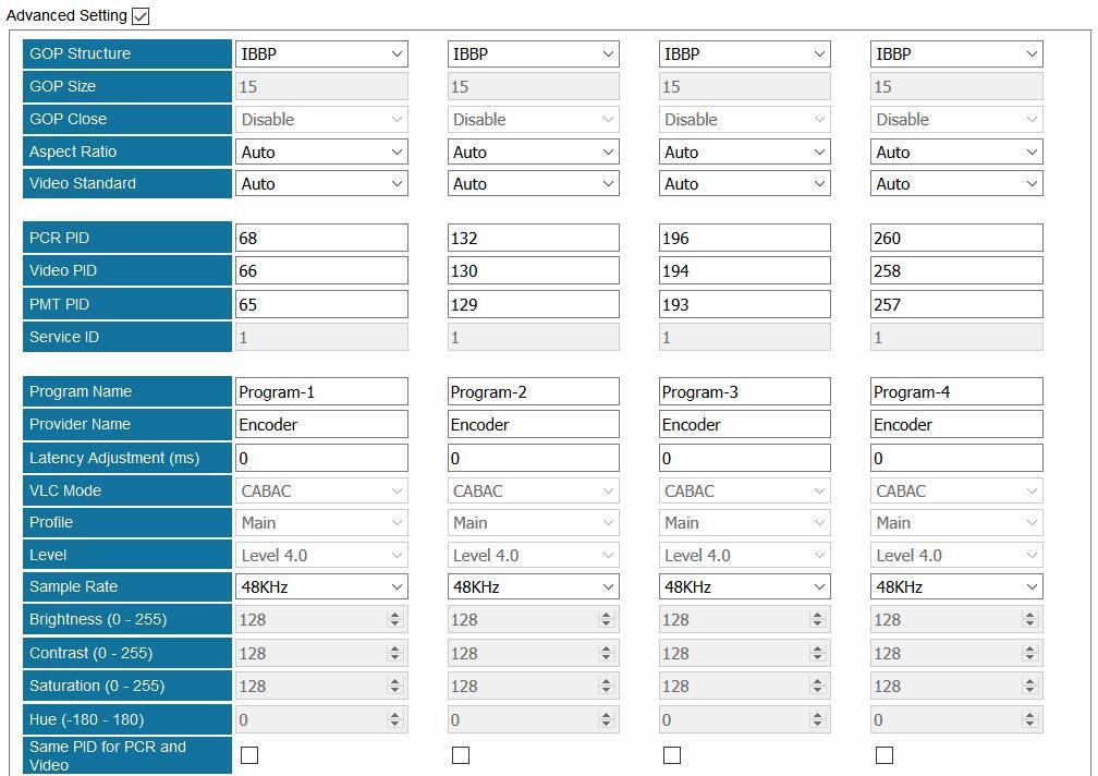
67 4.2.6 EN5-4H/1U Module Configuration > EN5-4H/1U 61
68 Name Range Name Range Work Mode SDI (HD x4) SDI (4K x1) Signal Lost Processing Blue screen Resolution 1920x1080_422_10_60P/59.94P/ Frame Ration Auto 60I/59.94I/50P/50I/30I/29.97P x1080_420_10_60P/59.94P x1080_422_8_60P/59.94P/ I/59.94I 1280x720_422_10_60P/59.94P 1280x720_422_8_60P/59.94P 720x576_420_8_50I 720x480_420_8_60I/59.94I Video PID Format 4:2:0, 4:2:2 Bit Depth 8 10 Profile Main, Main 10, Main Still Picture Level Auto, 4.0, 5.0, 5.1, 5.2, 6.0, 6.1, Bitrate (Kbps) 6.2 Tier Main 4:2:2 10 Main, High Advanced Setting Enable, Disable High Speed Mode Default (4k:High-Speed, others: Normal-Speed), Mode1 (4k,2k High-Speed. others: Normal-Speed), Mode2 (4k,2k,720p High- Speed. others: Normal- Speed) GOP Size (GOP_N) P_AS_L0_B P picture, L0 B picture Adaptive GOP Not insert, insert IDR Interval 0, 1, 2, 3, 4, 5 GOP Hierarchy Enable, Disable IP Period (GOP_M) Closed GOP Close, Open Adaptive Quantization 1, 2, 4 Off, On CPB Delay Default (3s), 0.5s,1s, 3s VBR Converge Off, On 62
 Dolby Mode Dolby Digital Plus AAC Version MPEG2, MPEG4 AAC Profile LC, HE, HE_V2 Volume SDI12 (db) -12~12 Volume SDI34 (db) -12~12 Volume")
69 Name Range Name Range Availability Enable, Disable Audio PID Audio Source SDI1_12, SDI1_34 Type MPEG1 LAYER2 SDI1_56, SDI1_78 AC3/EAC3 AAC Channel Layout Mono, Stereo, Surround Bitrate (Kbps) 32, 48, 56, 80, 96, 112, 128, 160, 192, 224, 256, 320, 384 Delay (ms) Dolby Mode Dolby Digital Plus AAC Version MPEG2, MPEG4 AAC Profile LC, HE, HE_V2 Volume SDI12 (db) -12~12 Volume SDI34 (db) -12~12 Volume SDI56 (db) -12~12 Volume SDI78 (db) -12~ Transcoding Modules TC4-xM2A TC4-xM2A module refers to TC4-2M2A or TC4-4M2A modules. TC4-2M2A supports transcoding to 2 H.264 HD/SD channels or 2 MPEG-2 SD channels. TC4-4M2A supports transcoding to 2 H.264 HD/SD channels or 4 MPEG-2 SD channels. AAC and AC3 audio encoding is available with optional hardware and license. 63

70 Module Configuration >TC4-XM2A01 64
, 1/0(C), 2/0(L, R) GOP")
71 Name Range Name Range Video Encode Rate 600~15000 Video Profile Main, High Audio Encode Rate 64~384 Video Level 3.0, 3.1, 3.2, 4.0, 4.1, 4.2 Audio Volume 0~8 Video Vlc Mode CABAC, CAVLC GOP Structure IPPB, IPPP Audio Encoder Type OFF, MPEG1_Layer2, AC3 IBP MPEG2_AAC, MPEG4_AAC GOP Size 6~63 AC3 AC Mode 1+1(L, R), 1/0(C), 2/0(L, R) GOP Close Disable, Enable Aspect Ratio Conversion Automatic, 16x9_LetterBox 16x9_CutOff, 4x3_PillarBox 4x3_CutOff Output Resolution 720x480_60i 720x576_50i 1920x1080_60i/50i 1208x720_60p/50p Latency Adjustment (ms) Enter a value to adjust the audio and video synchronization. Enter a positive value to delay audio encoding. Enter a negative value to hasten audio encoding. Video Encoder Type H264, MPEG2 SDHD 4SD/2HD channel mode. Drag a program to a TC4 output port for transcoding process. The transcoded program will be in the corresponding TC4 input port. Then the transcoded program can be sent to an output port. 65

72 4.4 Scrambling/Descrambling Modules CI Descrambling One CI module allows the user to insert two pairs of CAM and smartcard into two independent slots. The top slot is slot 1. The bottom slot is slot2. The user can either select Auto Reset or click Reboot to reset CAM modules. MMI button is used to read CAM and smartcard information. Module Configuration > CI Configuring Service Descrambling In the following image, a TS that contains 9 scrambled services comes from ASI input port. 1. Go to Status > CI and check the CAM Insert Status, CAM Initialization status, CAM Name, and CA System ID. Take the following figure for example, the CAM module is successfully loaded in CI Port. 66

![Then on the left side in Board3 [CI] Port1 the processed TS is listed as an input again. 3.](/docs-images/87/96188546/images/73-1.jpg "Right-click a program in the output CI port to descramble this service by the CAM in Port 1.")
![[Descramble] follows the service that is descrambled as a mark.](/docs-images/87/96188546/images/73-2.jpg "To cancel the descrambling process for the service, right-click it and click Non-descramble.")
73 2. Go to Service Configuration. Bypass the input TS and drag it to output Board3 [CI] on the right side. Then on the left side in Board3 [CI] Port1 the processed TS is listed as an input again. 3. Right-click a program in the output CI port to descramble this service by the CAM in Port 1. [Descramble] follows the service that is descrambled as a mark. To cancel the descrambling process for the service, right-click it and click Non-descramble. Click Apply. 4. Drag the service that has been descrambled from input Board3 [CI], Port1 to output port. 67


74 5. Go to Status > CI, check the Service Descramble Status. In the following figure, three services are descrambled successfully. 68

. Click Apply and then click Back to return to Service Configuration.")
75 4.4.2 CI-BISS Descrambling CI module can be converted to CI-BISS module by a different license and loading CI-BISS module software. BISS descrambling does not require any CAM module. Use the similar way as in Chapter CI Descrambling to configure CI-BISS Descrambling. 1. Bypass the input TS and drag it to output CI port. 2. Right-click a program and click BISS-Descramble. 3. Configure BISS Mode and BISS Key (and Injected ID in BISS-E Mode). Click Apply and then click Back to return to Service Configuration. [BISS_1] and [BISS_E] follow the descrambled services as a label. 69

76 4. Drag the descrambled services to output port. 5. Check descrambling status in Status > CI. To ensure CA PMT is updated in CI, better bypass the input TS before drag it to CI. Otherwise, descrambling process may fail Scrambler The scrambler module is use to work with CAS systems to encrypt programs. It supports scrambling up to 150 services. Besides, it support BISS-1/BISS-E scrambling without extra license. AES-CBC mode is optional. 70


, ECMG IP Address, and ECMG Port. Click Apply.")
77 The following figure gives an overview of Scrambler+ menu structure. Configuring Scrambler+ Setup Go to Module Configuration >Setup. Enter the IP Address, Subnet Mask, Gateway, and Speed Mode for this scrambler. The IP Address should be in the same network with that of the CAS server. The Speed mode should be the same with the Ethernet of CAS server. Turn on CA System 1 and keep unused CA Systems Off. Use a cross-through RJ45 cable to connect scrambler to CAS server s Ethernet port. Check the connection by pinging scrambler s IP address in the Command Prompt of CAS server. Configuring ECMG connection. Enter System ID, Sub System ID (keep it 0 if not required), ECMG IP Address, and ECMG Port. Click Apply. Check ECMG Communication Status in Status >Scrambler+. When the connection is liable, the status is a green Connected. See in the following figure. 71


78 Configuring EMMG connection. Enter EMMG TCP Port, EMMG UDP Port (keep it 0 if EMM Send Type is TCP), EMM Send Type, EMM PID, and EMM Bandwidth. Click Apply. Check EMMG Communication Status in Status >Scrambler+. When the connection is stable, the status should be a green Connected. Configuring ECM Add the AC Data that is created in CAS server into ECM List. 72
, CA Stream ID for each program and click Apply to scramble them. Go to Status > Scrambler+ and check ECM Count.")

79 Scrambling Programs Once the ECMG, EMMG connection is done and ECM is added, go to Service Configuration and right-click a program in output port to Program Scramble Setting. Select Slot (the slot in which Scrambler+ is installed), CA Stream ID for each program and click Apply to scramble them. Go to Status > Scrambler+ and check ECM Count. The count number should be the same with the number of scrambled programs. To cancel the scrambling process for a scrambled program, go to Program Scramble Setting again, set Slot to None and apply Non-scramble for this program. BISS-1/BISS-E Scrambling BISS scrambling does not require a CAS server. Right-click an output program to Program Scrambling Setting. Select BISS-1/BISS-E in Scrambling Type and enter BISS keys to scramble the programs. 73
80 Appendix A - Abbreviations Part 5 Appendices 8VSB 16VSB AAC AC-3 ASI ATSC AV BAT BER Bit Rate BNC CAM CAT CAT6 CBR CI CVBS db DVB EIT EPG FEC GOP HD HDCP HDMI Vestigial sideband modulation with 8 discrete amplitude levels Vestigial sideband modulation with 16 discrete amplitude levels Advanced Audio Coding Also known as Dolby Digital Asynchronous Serial Interface Advanced Television Systems Committee Audio Video Bouquet Association Table Bit Error Ratio The rate at which the compressed bit stream is delivered British Naval Connector Conditional Access Module Conditional Access Table Category 6 Cable standard for gigabit Ethernet Constant Bitrate Common Interface Composite Video Broadcast Signal Decibel Digital Video Broadcasting Event Information Table Electronic Program Guide Forward Error Correction Group of Pictures High Definition High-bandwidth Digital Content Protection High Definition Multimedia Interface 74
81 I/O Kbps LCN LNB LO Mbps MER MIB MPTS NIT OFDM PAT PCR PID PMT PSI PSU QAM QPSK SD SDI SDT SI SNMP SNR SPTS TDT TS VBR Input/output 1000 bit per second Logical Channel Number Low-Noise Block Local Oscillator 1,000,000 bits per second Modulation Error Ratio Management Information Base Multi-program Transport Stream Network Information Table Orthogonal Frequency-Division Multiplexing Program Association Table Program Clock Reference Packet Identifier Program Map Table Program Specific Information Power Supply Unit Quadrature Amplitude Modulation Quadrature Phase-Shift Keying Standard Definition Serial Digital Interface Service Description Table Service Information Simple Network Management Protocol Signal Noise Ration Single Program Transport Stream Time and Date Table Transport Stream Variable Bitrate 75
82 Appendix B Modules Available In Different Regions Check the following sheet to find out which modules are available in certain regions. Module Name North America Europe Other TSIP TSIP+ ASI IPASI DVBC DVBS2 DVBT2 8VSB QAM-A/C QAM-B IQAM OFDM 8VSBM HDMI/SDI Decoder Decoder-CC ASI-Switch DS3 ISDBT EN4AV EN4SDI EN4HDMI EN2SDI-2H EN4SC EN5-4H/1U TC4 CI CI-BISS Scrambler SQAM ENASDI-4S TCAVS Decoder AVS+ LQAM-A/C LQAM-B Available 76
83 Appendix C - Warranty We warrants this instrument against defects from any cause, except acts of God and abusive use, for a period of 1 (one) year from date of purchase. During this warranty period, we will correct any covered defects without charge. Appendix D - After-Sales Support Please contact our sales/regional representatives for any help, product information, and troubleshooting. Returning Products for Service The DMP00 is a delicate piece of equipment and needs to be serviced and repaired by the manufacturer. In order to expedite this process please carefully read the following items. Confirm the required component Before any product can be returned for service, the client ought to contact our sales representatives and after-sales support department by means of to confirm the need to return the product or part of the product. Collect the Serial Numbers to obtain RMA Number Serial Number (SN) is printed on a label on the chassis and modules. To create a RMA number, SN must be submitted to support department. Once the RMA number has been issued to the client, the unit/component needs to be packaged and shipped back to the manufacturer. It s best to use the original box and packaging for the product but if this not available, check with the service department for the proper packaging instructions. RMA Number should be specified in the delivery bill or written on the package. Do not return any power cables or accessories unless instructed to do so. 77
SMP100. User Guide V2.0-N
 SMP100 User Guide V2.0-N SMP00 User Guide Revision History Date Version Description Author 2/30/2013 1.0 First Draft AY 12/05/2016 1.06 New UI MS 6/30/2017 2.0-N Module Update HL This guide contains some
Simple Media Platform Quick Installation Guide V1.0-N. Simple Media Platform. Quick Installation Guide
 Simple Media Platform Quick Installation Guide 1. Installation Instruction 1.1 Mounting unit to a 19 rack When selecting the installation site, try to comply with the following: Protective Ground - The
Z-IP Stream 004/008. User Guide and Installation Manual. Four or Eight Input QAM Encoder / Modulator
 Z-IP Stream 004/008 User Guide and Installation Manual Four or Eight Input QAM Encoder / Modulator MPEG-2 / H.264 HD ENCODER with QAM /IP/ & ASI Outputs Contents Safety Precautions... 3 Package Contents...
AVE HOME FAGOR CVBS TO DVB-T ENCODER MODULATOR. Fagor Electr6nica
 AVE HOME CVBS TO DVB-T ENCODER MODULATOR FAGOR Fagor Electr6nica TABLE OF CONTENTS 1. SPECIFICATIONS... 12 1.1 Product Overview... 12 1.2 Appearance and Description... 12 1.3 Diagram... 13 1.4 Characteristics...
Operation and Installation Guide
 Operation and Installation Guide HDS2800 Series Encoder Modulator High Definition (HD) Digital COFDM MPEG2 and H.264 Modulator with IP Multicast. 19 Rack Mount Revision 4.0 Firmware version Released File
Operation and Installation Guide
 Operation and Installation Guide HDS2800 Series Encoder Modulator High Definition (HD) Digital COFDM MPEG2 and H.264 Modulator with IP Multicast. 19 Rack Mount Wall Mount Revision 0.1 Firmware version
HD-1603 Single Input MPEG-4 DVB-T HD Encoder/Modulator User Guide and Install Manual
 ZyCastR digi-mod HD Range digi-mod HD-1603 www.digi-modbyzycast.com HD-1603 Single Input MPEG-4 DVB-T HD Encoder/Modulator User Guide and Install Manual Table of Contents www.digi-modbyzycast.com Safety
HD4112 Quad HDMI MPEG2 HD DVBT Encoder Modulator U S E R M A N U A L
 HD4112 Quad HDMI MPEG2 HD DVBT Encoder Modulator U S E R M A N U A L HD4112 Manual Rev 1 Contents 1. GENERAL 1.1 Description 1.2 Specifications 2. INSTALLATION 2.1 What s in the Box 2.2 Connection 2.2.1
HD168Bi Quad CVBS/HDMI HD DVBT Encoder Modulator U S E R M A N U A L
 HD168Bi Quad CVBS/HDMI HD DVBT Encoder Modulator U S E R M A N U A L Contents 1. GENERAL 1.1 Description 1.2 Specifications 2. INSTALLATION 2.1 What s in the Box 2.2 Connection 2.2.1 DEVICE Programming
User s Manual HDMI Modulator ATSC 8VSB/QAM 65/256. Model No : HDM100
 User s Manual HDMI Modulator ATSC 8VSB/QAM 65/256 Model No : HDM100 Contents 1. Safety Instructions & Precautions. 1 2. Operation Guide.. 2 2-1. Connection Diagram. 2 2-2. Front Panel.... 3 2-3. Rear Panel.....
7881IRDA Series QUICK START GUIDE
 7881IRDA Series QUICK START GUIDE Copyright 2013-2015 EVERTZ MICROSYSTEMS LTD. 5292 John Lucas Drive, Burlington, Ontario, Canada L7L 5Z9 Phone: +1 905-335-3700 Sales: sales@evertz.com Fax: +1 905-335-3573
AES/EOU R-AUDIO2 R-AUDIO1 L-AUDIO1 L-AUDIO2 CVBS CVBS OUT R-AUDIO1 R-AUDIO2 ASI OUT2 GPI/LS DATA
 160R-Base R-AUDIO1 R-AUDIO2 AES/EOU ASI OUT RF OUT RF IN L-AUDIO1 L-AUDIO2 CVBS ASI IN GPI/LS DATA 160R-AD GPI/LS DATA CVBS OUT R-AUDIO1 R-AUDIO2 ASI OUT2 ASI IN2 RF OUT2 RF IN2 RF OUT1 RF IN1 Introduction
Digital Media Platform DMP900
 Digital Media Platform OVERVIEW The is Wellav s most advanced product for service operators. It provides proven headend technology in a compact, 1RU chassis. With over 30 different input and output module
Professional HD Integrated Receiver Decoder
 Professional HD Integrated Receiver Decoder User Manual V1.00-C Preface About This Manual This manual provides introductions to users about how to operate the device correctly. The content includes introduction
B-QAM-SDI-IP-2CH-LL User Manual
 User Manual Directory CHAPTER 1 INTRODUCTION... 1 1.1 PRODUCT OVERVIEW... 1 1.2 KEY FEATURES... 1 1.3 SPECIFICATIONS... 2 1.4 PRINCIPLE CHART... 3 1.5 APPEARANCE AND DESCRIPTION... 3 CHAPTER 2 INSTALLATION
SD4650 DVB-T HD MODULATOR. User Manual
 SD4650 DVB-T HD MODULATOR User Manual 0 TABLE OF CONTENT 1 GENERAL...2 1.1 Description...2 1.2 Specifications...3 2 INSTALLATION...4 2.1 What s in the Box...4 One power cable...4 2.2 Connection...4 2.2.1
QAM MODULATOR CI. 4 x DVB-S/S2/T/T2/C+CI 4 x DVB-T/C + IP. Operation Manual
 QAM MODULATOR CI 4 x DVB-S/S2/T/T2/C+CI 4 x DVB-T/C + IP Operation Manual 1 1. IMPORTANT SAFETY PRECAUTIONS INFORMATION READ THE FOLLOWING WARNINGS BEFORE YOU USE YOUR DEVICE WARNING The following safety
DM-1CH SD DVB-T MODULATOR INSTRUCTION MANUAL
 DM-1CH SD DVB-T MODULATOR INSTRUCTION MANUAL 2. Caution Statements and Table of Contents Table of Contents 2. Caution Statements and Table of contents 3. Important Safety Instructions 4. Important Safety
SPM x HDMI/AV to 1 x DVB-T/C Operation Manual
 SPM-2011 2 x HDMI/AV to 1 x DVB-T/C Operation Manual QM-Products 2016 v1.0 1 1. IMPORTANT SAFETY PRECAUTIONS INFORMATION READ THE FOLLOWING WARNINGS BEFORE YOU USE YOUR DEVICE WARNING The following safety
UMH160 Integrated Digital Receiver Quick Installation Guide
 UMH160 Integrated Digital Receiver Quick Installation Guide Wellav Technologies Ltd. 1 Preface About This Document This document provides introductions and guidelines to users about how to install and
Common Media Platform
 CMP100 Common Media Platform Introduction Remote Network Management Unified Access to the Signal 4RU High Density Design Dual Power Supply 16 Hot-Swappable Modules N+1 Input Backup 1+1 Output Backup Introduction
User guide. IP output module - Art. No A
 User guide IP output module - Art. No. 492072 891080A GB Contents Contents Disposal... 3 Box content... 3 IP output module... 3 Labels... 4 Installation of IP modules... 5 Installation of extender boards...
Professional 4-Channel DVB Receiver and Transmodulator Item: 5213
 IDLV-3440DM Professional 4-Channel DVB Receiver and Transmodulator Item: 5213 IDLV-3440DM integrates 4 DVB Receiver and Transmodulator in one 1U 19 chassis. It provides operators an ideal DTV headend setup
Table of Contents. 1. Safety Use. 2. General Description. 3. Connection Diagram. 4. Operations and Management. 4.1 Display Status. 4.
 DTM-HD01 Thank you for buying this encoder modulator. Please read this manual carefully to install, use and maintain the encoder modulator in the best conditions of performance. Keep this manual for future
AMD-53-C TWIN MODULATOR / MULTIPLEXER AMD-53-C DVB-C MODULATOR / MULTIPLEXER INSTRUCTION MANUAL
 AMD-53-C DVB-C MODULATOR / MULTIPLEXER INSTRUCTION MANUAL HEADEND SYSTEM H.264 TRANSCODING_DVB-S2/CABLE/_TROPHY HEADEND is the most convient and versatile for digital multichannel satellite&cable solution.
Installation & Operational Manual
 Radiant Communications Corporation 5001 Hadley Road South Plainfield NJ 07080 Tel (908) 757-7444 Fax (908) 757-8666 WWW.RCCFIBER.COM QRF5000M MDU ENCODER Installation & Operational Manual Rev.A2 1. Introduction
DVB IP CONVERTER FOR IPTV HEADENDS with INTEGRATED RECEIVER & DECODER & REMUXER
 DVB IP CONVERTER FOR IPTV HEADENDS with INTEGRATED RECEIVER & DECODER & REMUXER PRODUCT DESCRIPTION The DMM-151 is a high-density, cost-effective modular DVB to IP gateway system and DVB streamer for IPTV
DVB IP CONVERTER FOR IPTV HEADENDS with INTEGRATED RECEIVER & DECODER & REMUXER
 DVB IP CONVERTER FOR IPTV HEADENDS with INTEGRATED RECEIVER & DECODER & REMUXER PRODUCT DESCRIPTION The DMM-151/152 is a high-density, cost-effective modular DVB to IP gateway system and DVB streamer for
HD-1600 Single Input MPEG-4 DVB-T HD Encoder/Modulator User Guide and Install Manual
 digi-mod HD Range digi-mod HD-1600 www.resi-linx.com HD-1600 Single Input MPEG-4 DVB-T HD Encoder/Modulator User Guide and Install Manual Table of Contents Safety Precautions 2 Package Contents 2 Product
CompactMax-2 DVB-S/S2 TO DVB-T2 TRANSMODULATOR - 0 MI2100 -
 CompactMax-2 DVB-S/S2 TO DVB-T2 TRANSMODULATOR - 0 MI2100 - SAFETY NOTES Read the user s manual before using the equipment, mainly "SAFETY RULES" paragraph. The symbol on the equipment means "SEE USER
T3316 IP QAM Modulator User Manual
 T3316 IP QAM Modulator User Manual SW Version: 1.02 HW version: 0.70.0.0 Web NMS version: 1.02 Intended Audience About This Manual This user manual has been written to help people who have to use, to integrate
Web interface user guide MAC-HD REF High Definition Standalone Modulator DVB-T / DVB-C / IP Outputs 2xCVBS. HDMI.
 Web interface user guide MAC-HD REF. 4493 High Definition Standalone Modulator DVB-T / DVB-C / IP Outputs 2xCVBS. HDMI. HD-SDI Inputs Index 4 Introduction 4 About this Manual 4 Product Description 5 Web
HD Digital MPEG2 Encoder / QAM Modulator
 HD Digital MPEG2 Encoder / QAM Modulator HDMI In QAM Out series Get Going Guide ZvPro 800 Series is a one or two-channel unencrypted HDMI-to-QAM MPEG 2 Encoder / QAM Modulator, all in a compact package
user manual Colosseum 8500D
 user manual Colosseum 8500D No part of this manual may be copied, reproduced, transmitted, transcribed or translated into any language without permission. Unitron reserves the right to change the specifications
Advanced Receiver Decoder Card
 Advanced Receiver Decoder Card AG 5800 opengear Module SATELLITE INPUT OVERVIEW MPEG/IP INPUT ASI INPUT The AG 5800 card-based receiver decoder provides an ideal solution for 4:2:2 video decoding where
QAM HD Integrated Receiver Decoder with SDI/HDMI/ASI/IP Signal Outputs. User Manual B-IRD-HD-PRO-Q HD IRD
 QAM HD Integrated Receiver Decoder with SDI/HDMI/ASI/IP Signal Outputs User Manual B-IRD-HD-PRO-Q HD IRD DIRECTORY Chapter 1 Product Outline... 1 1.1 Outline... 1 1.2 Features... 1 1.3 Specifications...
Digital CATV Head End Modular Bank
 Digital CATV Head End Modular Bank User Manual (ver. A) http://www.pbi-china.com 目录 1. SUMMARY...1 2. BASIC OPERATION ON HDMS...2 2.1 Minimum requirements for PC...2 2.2 Installation...2 2.3 Edit IP addresses
HD Digital Set-Top Box Quick Start Guide
 HD Digital Set-Top Box Quick Start Guide Eagle Communications HD Digital Set-Top Box Important Safety Instructions WARNING TO REDUCE THE RISK OF FIRE OR ELECTRIC SHOCK, DO NOT EXPOSE THIS PRODUCT TO RAIN
Professional HD Integrated Receiver Decoder
 Professional HD Integrated Receiver Decoder GEOSATpro DSR-180ASI with 708CC User Manual V1.00-C For Support, call 888-483-4673 Preface About This Manual This manual provides introductions to users about
User guide MAW-300. Ref HD Encoder & Modulator HDMI to DVB-T
 User guide MAW-300 Ref. 3030 HD Encoder & Modulator HDMI to DVB-T 1 Index Safety Instructions... 3 General Description... 4 Working Principie... 4 Technical Specifications... 5 Installations... 6 Typical
HD Digital MPEG2 Encoder / QAM Modulator
 HD Digital MPEG2 Encoder / QAM Modulator YPrPb VGA In QAM Out series Get Going Guide ZvPro 600 Series is a one or two-channel Component or VGA-to-QAM MPEG 2 Encoder/ Modulator, all in a compact package
TP160 IRD. Professional HD Integrated Receiver Decoder User Manual V1.0RC
 TP160 IRD Professional HD Integrated Receiver Decoder User Manual V1.0RC Preface Symbols Definition For the symbols that might appear in this document, the meanings they represent are as the following:
Applications & Features of the SB- SDQM- 2130
 Applications & Features of the SB- SDQM- 2130 Retrofit Existing 12 in 1 Analog Head Ends Into Standard Definition QAM Analog to Digital in one easy step Allows insertion of operators scrambled programming
Web interface user guide MHD-201 REF High-definition modulator
 Web interface user guide MHD-201 REF. 3854 High-definition modulator Index 4 Introduction 4 About this Manual 4 Product Description 5 Web interface connection 5 Ethernet configuration by application IKUSI
CAUTION RISK OF ELECTRIC SHOCK NO NOT OPEN
 Evolution Digital HD Set-Top Box Important Safety Instructions 1. Read these instructions. 2. Keep these instructions. 3. Heed all warnings. 4. Follow all instructions. 5. Do not use this apparatus near
Release Notes for GT42 Universal descrambler Module
 GT42W: SW 3.0.2 2016-11-28, JÅ Release Notes for GT42 Universal descrambler Module Content 1 Release Notes for SW 3.0.2 (GT01W GT11 SW 3.1)... 2 1.1 About this document... 2 1.2 About this release... 2
Evolution Digital HD Set-Top Box Important Safety Instructions
 Evolution Digital HD Set-Top Box Important Safety Instructions 1. Read these instructions. 2. Keep these instructions. 3. Heed all warnings. 4. Follow all instructions. 5. Do not use this apparatus near
User manual Transmodulators. Ref. 5103S/5103T/5103Q/5130
 User manual Transmodulators Ref. 5103S/5103T/5103Q/5130 Contents 1 Introduction 2 1.1 The ProQuad range................................ 2 1.2 Modular system solution.............................. 4 1.3
DIGICAST DTVANE. DMB-9020 HD Professional IRD OVERVIEW
 OVERVIEW Conforming to MPEG-2(MP@ML), DMB-9020 HD Professional IRD supports DVB-S2 Tuner standard, and adopts high-quality decoding of MPEG-2, MPEG-4, and H.264 in broadcast level. Its CI descrambling
CHENGDU DEXIN DIGITAL TECHNOLOGY CO., LTD
 NDS3208 8 in 1 MPEG-2 Encoder User s Manual NMS Version: 1.12.5 SW: 2.07 HW: 1.3 CHENGDU DEXIN DIGITAL TECHNOLOGY CO., LTD DIRECTORY Chapter 1 Product Introduction... 1 1.1 Outline... 1 1.2 Main Features...
TV4U QUAD DVB-S2 to DVB-C TRANSMODULATOR
 INSTRUCTION MANUAL Features of the new DVB-C transmodulators line Through the use of the FPGA technology the transmodulators provides the highest performance at the lowest price. Four carriers are formed
CompactMax-4 DVB-S/S2 TO ISDB-T TRANSMODULATOR - 0 MI2101 -
 CompactMax-4 DVB-S/S2 TO ISDB-T TRANSMODULATOR - 0 MI2101 - SAFETY NOTES Read the user s manual before using the equipment, mainly "SAFETY RULES" paragraph. The symbol on the equipment means "SEE USER
2 HDMI to DVB-T Encoder Modulator
 2 HDMI to DVB-T Encoder Modulator (MPEG-2 HD/MPEG-4 HD Encoding + DVB-T Modulating) SW Version: 1.07 HW version: 0.6 Web NMS version: 1.03 Date: 27 th NOV, 2012 Intended Audience About This Manual This
Model#: IN-MDRI3MF. Hardware User Manual. 3MP Indoor Mini Dome with Basic WDR, Fixed lens. (PoE) Ver. 2013/02/04
 Ver. 2013/02/04") Model#: IN-MDRI3MF 3MP Indoor Mini Dome with Basic WDR, Fixed lens Hardware User Manual (PoE) Ver. 2013/02/04 Table of Contents 0. Precautions 3 1. Introduction 4 Package Contents... 4 Features and Benefits...
Model#: IN-MDRI3MF 3MP Indoor Mini Dome with Basic WDR, Fixed lens Hardware User Manual (PoE) Ver. 2013/02/04 Table of Contents 0. Precautions 3 1. Introduction 4 Package Contents... 4 Features and Benefits...
MyM-3S Micro Master. Installation Guide. English. design for TV
 MyM-3S Micro Master Installation Guide design for TV 1 CONTENT 1. Introduction 2. Unpacking the unit 3. Connections and indications 4. IP settings 5. Menus and settings 5.1 Overview menu 5.2 Input settings
DCP Internet DCP-1000AV SDI/HDMI/AES & XLR
 Digital TV Equipment System Digital Contents Processing Platform DCP-1000 brings a compact flexible solutions that allow the users to build or update the DTV or IPTV headend to meet a variety of requirements
MediaKind RX
 MediaKind RX8330 The MediaKind RX8330 Distribution Receiver provides feature-rich multi-format standard definition decoding capability with high quality SDI output for video distribution applications.
MyM Pro 3S/6S Installation guide
 MyM Pro 3S/6S Installation guide CONTENT 1. Introduction 2. Unpacking the unit 3. Connections and indications 4. IP settings 5. Menus and settings web ui 5.1 Overview menu 5.2 Input settings 5.3 Output
TGX-4400 Professional Receiver Decoder
 TGX-4400 Professional Receiver Decoder User Manual June 2017 8032R www.technalogix.ca 1.403.347.5400 Revision 1.2 Safety Instructions Read these instructions Keep these instructions Heed all warnings Follow
Cisco D9859 Advanced Receiver Transcoder
 Deliver MPEG-4 high-definition (HD) services to MPEG-2 cable TV (CATV) headends with the Cisco D9859 Advanced Receiver Transcoder. The Cisco D9859 platform (Figures 1 and 2) extends the distribution options
Cisco D9859 Advanced Receiver Transcoder
 Data Sheet Cisco D9859 Advanced Receiver Transcoder Deliver MPEG-4 high-definition (HD) services to MPEG-2 cable TV (CATV) headends with the Cisco D9859 Advanced Receiver Transcoder. The Cisco D9859 platform
User manual. QAM output module. QAM output module Version F Date 08/2016 EN
 QAM output module Model Item no. QAM output module 492055 492056 Version F Date 08/2016 EN Attention! / Achtung! / Consignes de sécurité! EN Failure to comply with the specified precautionary measures
Thor Broadcast SDI-DVBT-IP & SDI-DVBT-IPLL Product Lines
 700-1200 ms 1080p60 70-125 ms (LL) H-4SDI-DVBT-IP H-4SDI-DVBT-IP 4x HD-SDI 1080p60 700-1200 ms 70-125 ms (LL) Data Sheet: H-1/4SDI-DVBT-IP User s Manual: H-1/4SDI-DVBT-IP Thor Broadcast SDI-DVBT-IP & SDI-DVBT-IPLL
Portable TV Meter (LCD) USER S MANUAL
 USER S MANUAL") 1 Portable TV Meter User Manual (LCD) Portable TV Meter (LCD) USER S MANUAL www.kvarta.net 1 / 19 2 Portable TV Meter User Manual (LCD) Contents 1. INTRODUCTION... 3 1.1. About KVARTA... 3 1.2. About DVB...
1 Portable TV Meter User Manual (LCD) Portable TV Meter (LCD) USER S MANUAL www.kvarta.net 1 / 19 2 Portable TV Meter User Manual (LCD) Contents 1. INTRODUCTION... 3 1.1. About KVARTA... 3 1.2. About DVB...
Table of Contents FCC COMPLIANCE STATEMENT... 4 WARNINGS AND PRECAUTIONS... 4 WARRANTY... 5 STANDARD WARRANTY... 5 TWO YEAR WARRANTY... 5 DISPOSAL...
 1 Table of Contents FCC COMPLIANCE STATEMENT... 4 WARNINGS AND PRECAUTIONS... 4 WARRANTY... 5 STANDARD WARRANTY... 5 TWO YEAR WARRANTY... 5 DISPOSAL... 6 1. INTRODUCTION... 7 FEATURES... 7 2. CONNECTIONS
GX Operation Guide. Digital Contents Processing Platform. Digital Headend System. Version 1.0. Solution. System. Service.
 Digital Headend System GX-5000 Digital Contents Processing Platform GX-5000 Operation Guide Version 1.0 About this Guide Thank you for purchasing the digital TV headend equipment from ANTIK. This operation
Digital Video Recorder
 Digital Video Recorder Quick Operation Guide UD.6L0202B0067A02 Thank you for purchasing our product. If there is any question or request, please do not hesitate to contact dealer. This manual is applicable
QRF5000 MDU ENCODER. Data Sheet
 Radiant Communications Corporation 5001 Hadley Road South Plainfield NJ 07080 Tel (908) 757-7444 Fax (908) 757-8666 WWW.RCCFIBER.COM QRF5000 MDU ENCODER Data Sheet Version 1.1 1 Caution Verify proper grounding
VECOAX ULTRA-8 is a Eight channels HDMI Modulator to channels to distribute HD Video Over coax with real time perfect quality
 VECOAX ULTRA-8 is a Eight channels HDMI Modulator to channels to distribute HD Video Over coax with real time perfect quality Key Features Converts up to Eight HDMI video sources into 8 HDTV Channels you
User Manual. UNIVERSE Ref. 8600
 User Manual UNIVERSE Ref. 8600 No part of this manual may be copied, reproduced, transmitted, transcribed or translated into any language without permission. Unitron reserves the right to change the specifications
IxStream Headend. Quick Guide - Begin working with the IxStream headend. IX-Streamer, rev 1.1
 IxStream Headend Quick Guide - Begin working with the IxStream headend IX-Streamer, rev 1.1 Introduction... 3 Example setup... 3 Access the headend... 4 Important Concepts... 5 Push Config... 5 EMM...
-TECH DIGITAL. Explore The High DefinitionWorld. Website: Hot Line: [US] USER MANUAL
![-TECH DIGITAL. Explore The High DefinitionWorld. Website: Hot Line: [US] USER MANUAL](/thumbs/80/80689593.jpg "-TECH DIGITAL. Explore The High DefinitionWorld. Website: Hot Line: [US] USER MANUAL") -TECH DIGITAL Explore The High DefinitionWorld Website: www.jtechdigital.com Hot Line: 1-888-610-2818[US] USER MANUAL J-Tech Digital ProAV H.264 Encoder/Decoder Many to Many HDMI Extender RoHS 1 Operating
-TECH DIGITAL Explore The High DefinitionWorld Website: www.jtechdigital.com Hot Line: 1-888-610-2818[US] USER MANUAL J-Tech Digital ProAV H.264 Encoder/Decoder Many to Many HDMI Extender RoHS 1 Operating
QRF5000 MDU ENCODER AND QAM MODULATOR
 Radiant Communications Corporation 5001 Hadley Road South Plainfield NJ 07080 Tel (908) 757-7444 Fax (908) 757-8666 WWW.RCCFIBER.COM QRF5000 MDU ENCODER AND QAM MODULATOR Installation & Operational Manual
OmniHub CMP201 CMP203 INTRODUCTION
 OmniHub RESET Module Status 1 2 3 4 5 6 CMP201 OmniHub MGMT1 MGMT2 DATA1 DATA2 CMP201 Module Status 1 2 3 4 5 6 CMP203 RESET OUT OmniHub MGMT1 MGMT2 DATA1 DATA2 CMP203 INTRODUCTION OmniHub is a new generation
Single & Dual Input HD Digital DVB-T Modulators
 Radio Frequency Range Installation Diagram digi-mod HD-1000DM / HD-2000DM www.resi-linx.com Single & Dual Input HD Digital DVB-T Modulators ANT IN 1 2 3 4 AUX MOD RF IN TV OUTPUTS MOD RF IN (PWR/IR PASS)
DX3316 IP QAM Modulator User Manual
 DX3316 IP QAM Modulator User Manual SW Version: 1.02 HW version: 0.70.0.0 Web NMS version: 1.02 DEXIN DIGITAL TECHNOLOGY 20142014 CORP. LTD. Intended Audience About This Manual This user manual has been
Refs , HDTV ENCODER/MODULATOR - Dual Component to QAM HDTV ENCODER/MODULATOR - Dual Component to QAM (EAS) QUICK INSTALLATION GUIDE
 QUICK INSTALLATION GUIDE") Refs. 563801, 563811 EN (EAS) QUICK INSTALLATION GUIDE w w w. t e l e v e s. c o m Safety instructions Caution statements Product inspection - Inspect the equipment for shipping damage. Should any damage
Refs. 563801, 563811 EN (EAS) QUICK INSTALLATION GUIDE w w w. t e l e v e s. c o m Safety instructions Caution statements Product inspection - Inspect the equipment for shipping damage. Should any damage
Check our knowledge base at
 USER MANUAL Check our knowledge base at www.paralinx.net/support Copyright 2015 Paralinx LLC All Rights Reserved TABLE OF CONTENTS 1 Important Notice 10 LCD Screen 2 Safety Instructions 11 Indicators 3
Professional 8-in-1 TS Processor MX5308 USER MANUAL 2015/06
 Professional 8-in-1 TS Processor MX5308 USER MANUAL 2015/06 MX5308 8-in-1 TS Processor License Declaration Without the prior written permission of ANTIK Technology, no part of this manual shall be added
4 HDMI & Component HD to COAX and IPTV HD 480i/720p/1080i/1080p CC Modulator
 Product Information Datasheet 4 HDMI & Component HD to COAX and IPTV HD 480i/720p/1080i/1080p CC Modulator 4 HDMI Digital RF modulator QAM, ATSC, DVB-T, ISDB-T, HDCP compliant modulator, HD Modulator Over
NDS3542 Encoder Modulator Low Delay
 NDS3542 Encoder Modulator 2*SDI/HDMI 2* DVB-T Carriers Out Low Delay Front View Rear View SDI Input Rear View HDMI Input Key Features MPEG2 HD & MPEG4 AVC/H.264 HD video encoding Up to 1920*1080@50P/60P
Product Introduction. Key Features
 NDS356xH HD IRD Product Introduction NDS356xH HD IRD is DEXIN s all-in-one device which integrates demodulation, de-scrambler, re-mux and decoding in one case to convert RF signals into audio/video (CVBS
HD Digital MPEG2 Encoder / QAM Modulator Get Going Guide
 series HD Digital MPEG2 Encoder / QAM Modulator Get Going Guide HDb2640 HDb2620 HDb2540 HDb2520 The HDbridge 2000 Series is a combination HD MPEG 2 Encoder and frequency-agile QAM Modulator, all in a 1RU
Model#: IN-DI2MIRF 2MP Indoor Dome with True Day/Night, IR, Basic WDR, Fixed lens
 Model#: IN-DI2MIRF 2MP Indoor Dome with True Day/Night, IR, Basic WDR, Fixed lens Hardware User Manual (PoE) Ver.2013/01/17 Table of Contents 0. Precautions 3 1. Introduction 4 Package Contents...4 Features
4IN1 IP QAM Modulator USER S MANUAL
 4IN1 IP QAM Modulator USER S MANUAL Catalog 1. SAFETY INSTRUCTION... 1 2. SYSTEM DIAGRAM AND WORK PRINCIPLE... 1 2.1 SYSTEM DIAGRAM... 1 2.2 WORKING PRINCIPLE... 2 3 FEATURE... 3 4 SPECIFICATIONS... 4
Multi-CODEC 1080P IRD Platform
 Multi-CODEC 1080P IRD Platform RD-70 The RD-70 is a 1080P multi-codec very low latency MPEG 2 and MPEG 4 AVC/H.264 high definition IRD. The ultra-low delay mode requires the use of Adtec s EN-91 1080i,
8-Way Professional Demodulator & IPTV Streamer
 8-Way Professional Demodulator & IPTV Streamer Model: Main Feature: 8 DVB-S2/S, DVB-C, DVB-T2/T or DTMB or ATSC or ISDB-T Tuner Inputs Tuner RSSI, received signal strength, Eb/N0, C/N and BER monitoring
12 HDMI 16* DVB-C/8*DVB-T/6*ISDB-T Digital RF
 NDS3544M Encoder Modulator 12 HDMI 16* DVB-C/8*DVB-T/6*ISDB-T Digital RF Product Overview NDS3544M HD encoder modulator is a professional high integration device which includes encoding, multiplexing,
OPERATION MANUAL. USF-1013DEMUX Digital Audio Demultiplexer. 2 nd Edition. Software Version Higher
 OPERATION MANUAL USF-1013DEMUX Digital Audio Demultiplexer 2 nd Edition Software Version 2.00 - Higher Precautions Important Safety Warnings [Power] Stop [Circuitry Access] Do not place or drop heavy or
DVISm. DVISm - Mini Digital Video Insertion System. Quick Start Guide. Patent Pending
 DVISm Patent Pending DVISm - Mini Digital Video Insertion System Quick Start Guide Although every effort has been taken to ensure the accuracy of this document it may be necessary, without notice, to make
AVP 3000 Voyager.
 AVP 3000 Voyager The AVP 3000 Voyager is MediaKind s sixth generation DSNG product and is the most flexible and scalable news gathering system on the market, reflecting MediaKind s technology leadership
Professional Quad HDTV IRD
 Professional Quad HDTV IRD User Manual http://www.pbi-china.com Contents 1. Overview... 4 2. Features... 5 3. Technical Specifications... 5 4. Block Diagram... 10 5. Front panel and rear panel instructions...
Television on IP Networks. BNS-200 (Ref. 5105) Double A/V IP Streamer. Configuration and Settings. User Manual
 Double A/V IP Streamer. Configuration and Settings. User Manual") Television on IP Networks BNS-200 (Ref. 5105) Double A/V IP Streamer Configuration and Settings User Manual EN Configuration and Setting of the BNS-200 Streamer Module User Manual November 2008 Revision
Television on IP Networks BNS-200 (Ref. 5105) Double A/V IP Streamer Configuration and Settings User Manual EN Configuration and Setting of the BNS-200 Streamer Module User Manual November 2008 Revision
1 x HDMI to DVB-T (COFDM) "Home" modulator HDMOD-4
 Home modulator HDMOD-4") 1 x HDMI to DVB-T (COFDM) "Home" modulator HDMOD-4 Operation Manual Lemco HDMOD-4 manual v1.0 1 1. IMPORTANT SAFETY PRECAUTIONS INFORMATION READ THE FOLLOWING WARNINGS BEFORE YOU USE YOUR DEVICE WARNING
1 x HDMI to DVB-T (COFDM) "Home" modulator HDMOD-4 Operation Manual Lemco HDMOD-4 manual v1.0 1 1. IMPORTANT SAFETY PRECAUTIONS INFORMATION READ THE FOLLOWING WARNINGS BEFORE YOU USE YOUR DEVICE WARNING
Digital Tuner Streamer
 Digital Tuner Streamer This Manual Apply to the MTRX 4/8 Tuner To IPTV Systems On 8 Tuners Systems, The inputs are all assigned to the 8 Tuners Only and no asi Web-NMS Version: 1.03 Software: 1.00 Hardware:
16 channels transmodulator S2C16
 16 channels transmodulator S2C16 Vers. 1.01 USER S MANUAL S2C16 - SAT to QAM transmodulator 1. Product description S2C16 is a 16 channel transmodulator with DVB-S/S2 input and DVB-C output. It has 4 main
MyM Pro T2 Installation guide
 MyM Pro T2 Installation guide CONTENT 1. Introduction 2. Unpacking the unit 3. Connections and indications 4. IP settings 5. Menus and settings web ui 5.1 Overview menu 5.2 Input settings 5.3 Output settings
Network Video Decoder NVD-20. Contents
 Contents Warnings and Precautions... 4 Warranty... 5 Standard Warranty... 5 Two Year Warranty... 5 Disclaimer of Product & Services... 6 Disposal... 6 Packing List... 6 Product Overview... 7 Features...
FS3. Quick Start Guide. Overview. FS3 Control
 FS3 Quick Start Guide Overview The new FS3 combines AJA's industry-proven frame synchronization with high-quality 4K up-conversion technology to seamlessly integrate SD and HD signals into 4K workflows.
DMOD1200MS. HDMI Modulator. User Manual PLEASE READ THE MANUAL COMPLETELY BEFORE USE V.17.09
 DMOD1200MS HDMI Modulator User Manual PLEASE READ THE MANUAL COMPLETELY BEFORE USE V.17.09 CONTENTS 1. INTRODUCTION 1.1. Product Description 1.2. Package Contents 1.3. Hardware Installation 1.4. Safety