SLAC ILC program, International BDS Design, ATF2 facility
|
|
|
- Kerry Morton
- 5 years ago
- Views:
Transcription
1 1 May 3, 2005 SLAC ILC program, International BDS Design, ATF2 facility Andrei Seryi May 3, 2005 Seminar at CERN
2 2 May 3, 2005 Contents SLAC ILC program» following the outline given by Tor Raubenheimer Very exciting strong program addressing most of the design issues SLAC program addresses 14 of the 15 R2 items identified by the 2003 TRC report as well as many additional problems Program is focused on overall accelerator design issues as well as a few technology development concepts International design of the ILC BDS
3 3 May 3, 2005 SLAC ILC Program Program for FY05/FY06 has six main elements Electron and Positron sources Damping rings Beam Delivery System and Interaction Region Overall design: Beam parameters, Optics, Emittance preservation, Stability/alignment, Instrumentation, Availability, MPS, and Operational issues Conventional construction implications and site development Linac rf technology klystrons, modulators, rf distribution, and possibly couplers Wakefields and cavity optimization Not SC Cavity fabrication
4 4 May 3, 2005 System Design Extensive simulation of sub-systems Balance emittance budgets and specify system tolerances impact on overall beam parameters Consider operational issues Design for availability and work on detailed models big impact on layouts and configuration but hard to quantify Develop beam tuning algorithms specify beam instrumentation requirements and layout Consider high-level controls software requirements (applications) for beam control specify control system requirements Develop Machine Protection Scenarios Specify active and sacrificial protection systems Specify beam dumps and beam tuning stations
5 5 May 3, 2005 Major Test Facilities NLCTA Complete X-band program Create new L-band rf Test Facility Test klystron and modulators for ILC Test normal conducting structures for e+/e- sources Construct coupler test facility Facilities also available in Klystron Test Lab End Station A Study Interaction Region issues and instrumentation Mockup of full IR ATF-2 Test BDS using very low emittance beam Utilize other test facilities around the world (TTF, SMTF, STF, ATF)

 longitudinal feedback, etc.")
6 6 May 3, 2005 UK/US/KEK team at ATF, march 2005 MB emittancestudy Wiggler study High quality beam extraction nm resolution BPM test & demonstration Fast feedback test & demonstration Fast Kicker for ILC damping ring Instrumentation developments (LW, XSR monitor, ODR monitor, MB-BPM, (SB, MB) longitudinal feedback, etc.) Preparation of ATF-2
7 7 May 3, 2005 Electron and Positron Source Electron source Continuing photocathode development Creating space to begin laser and gun development Positron source (program with LLNL) Studying target design for undulator, conventional, and Compton sources Radiation damage Thermal shock / beam damage Engineering issues (high rotation speed, remote handling) NC capture structure design and fabrication Capture and optics studies Complete E-166 polarized positron production (spring 2005)
8 8 May 3, 2005 Damping Rings Damping ring design (program with LBNL) Optics and tuning studies Collective effects Bunch compressor design SEY Studies (program with LBNL) Laboratory measurements in PEL Building three chambers for PEP-II installation to verify solutions ATF at KEK (for DR and BDS) Instrumentation (NanoBPM, laser wires, optical anchor) Beam studies (ORM, BBA, FBII, Wiggler) ATF Kicker replacement ATF stripline kicker development FONT/Feather
9 Electron Cloud Simulations Electron Electron density density in in units units of of e m 3 3 as as a function function of of time time for for an an arc arc bend bend in in the the 6km 6km DR DR option option assuming assuming a beam beam pipe pipe radius radius 22mm 22mm and and including including an an antechamber antechamber design design (full (full height height h=10mm). h=10mm). 9 May 3, 2005


10 10 May 3, 2005 SEY Studies in PEP LER Building test inserts chambers for PEP-II test chamber with coated samples Two grooved chambers to verify a proposal by Mauro Pivi and Gennady Stupakov
11 11 May 3, 2005 Linac Design Quadrupole alignment Use a SC linac quadrupole from DESY to study shunting alignment ability very important to achieve desired tolerances Continue program for NC quadrupoles BPM tests (program with TTF, ATF and LCLS) Develop and test high resolution BPMs Cavity diagnostics (program at TTF) Add HOM detectors to SC cavities at TTF to determine beam-cavity location very important especially for high shunt impedance cavities with small aperture Measure vibration due to SC cryogenic equipment Important for conventional layout and BDIR

12 12 May 3, 2005 Superconducting Quadrupole Goal Demonstrate Linac Quad/BPM performance required for ILC Verify ~ 5 micron stability of quad magnetic center Show ~ 1 micron BPM resolution and < ~ 5micron quad-to-bpm stability in compact, 80 mm aperture design. Approach Test TESLA prototype quad built by CIEMAT in Spain and BPM developed at SLAC Plan Build cryostat for prototype quad and test at Magnetic Measurements Lab with rotating coil. Do beam tests of BPM and eventually integrate quad and BPM for test in LI02

13 13 May 3, 2005 Cavity HOM Measurements Understanding HOM signals from TTF Instrumentation used to measure HOMs in the TTF cavities Analysis was complicated because timing system was noisy Seem to achieve resolutions at the 16 micron level Questions about relative alignment of modes Potential to be very useful 16 um resolution comparing against other modes

14 14 May 3, 2005 Wakefield Calculations Extensive 3-D modeling of the TESLA and the new Low-Loss SC cavity wakefields Big computation: 768 processors and requires 300 GB memory Mode rotation may be an important source of jitter Need to understand if this is mostly systematic due to the coupler orientation or due to fabrication errors Huge effect if it is systematic New Low Loss cavities have lower cryoloads but higher wakes Big impact on design may make 35 or 40 MV/m possible Need to understand the wakefield implications

15 15 May 3, 2005 Modulators ILC baseline modulator was developed in the early 90 s at FermiLab for use with the TTF Advantages: Simple circuit topology Proven design; 10+ years of operation Disadvantages: High stored energy 270kJ Massive pulse transformer 6.5 tons Single-point failures can damage klystron Requires large floor area Insulating oil 100 s of gallons SLAC effort is evaluating options, e.g. Marx generator style which should provide similar efficiency and 100% availability


16 Marx Generator Modulator Stack of 12 kv units Pros Uses emerging technology Modular design for longer MTBF and shorter MTTR No oil; compact unit No magnetic core Finer waveform control Cons Uses emerging technology IGBT controls floats at high voltage during the pulse DC power flow must be isolated Timing signals must cross high voltage gradients 16 May 3, 2005


 of these to")
17 17 May 3, 2005 Klystrons Three industrial vendors for baseline 10MW MBK tubes Still very little real experience with multi-beam klystrons Develop L-band sheet beam klystron an alternate to the MBK tubes significant cost reduction High efficiency design using flat beams instead of 6 beamlets Smaller with simpler focusing, cavities, and cathodes Study klystron / modulator options More conservative 5MW tube or lower power PPM tubes Decide which (if any) of these to pursue further
18 18 May 3, 2005 End Station B Program Complete X-band program at NLCTA Test CERN structure and other gradient studies Test active switching technology Expect to decommission 8-pac modulator this year Start construction of an L-band test facility Create facility to construct prototype collimators for the LHC Adaptation of NLC consumable collimator technology to allow the LHC to reach design luminosity Support E-163 laser acceleration experiment


19 19 May 3, 2005 ESB L-Band Test Facility Build L-band test facility in ESB Test modulators and klystrons Test NC accelerator structures and couplers

 SNS Modulator FNAL 2095")
20 20 May 3, 2005 ESB L-Band Test Facility Modulator will be delivered from SNS this summer Scrounging klystron parts from SDI/Anthrax/etc programs Buying 5 MW tube from Thales (1 year delivery) SNS Modulator FNAL 2095 Klystron

21 21 May 3, 2005 Normal Conducting Structure Proposed Structure Design for Positron Source with Mechanical Simplicity, effective cooling and Low Pulsed Heating: e+ capture: heating 5kW/cell due to RF & 7.5kW/cell due to particle losses Working Progress: Preliminary electrical and cooling design Ready to start mechanical design Will build 5 cell cavity and operate at NLCTA with 5MW source


22 22 May 3, 2005 Work on LHC collimation Create facility to construct prototype collimators for the LHC Adaptation of NLC consumable collimator technology to allow the LHC to reach design luminosity CERN Carbon 1 st stage collimator

23 End Station A 23 May 3, 2005 Significant international interest BDS & MDI instrumentation studies, collimator wakefield studies Construct IR mock-up
24 International design of BDS 24 May 3, 2005 Daresbury, RHUL, QMUL, Oxford, UCL, LAL, CEA/Saclay, CERN, BINP, DESY, INFN, KEK, Tokyo University, Kyoto ICR, IHEP, Pohang AL, SLAC, BNL, Fermilab, LLNL, Universities, and many other Truly international efforts Organization, communication and coherency of efforts is improving Estimation > 100 people are involved in machine and machinedetector aspects of BDS Arriving to baseline configuration at the end of 2005 require better organization of existing efforts Producing CDR with cost at the end of 2006 require increase of engineering support
25 25 May 3, 2005 Stages of BDS design toward CDR Present stage: From concepts to optics & from boxes on the layout to Geant models The goal is to mostly finish with this before Snowmass Next stage: Performance studies and small optimization of the design & DR to IP studies for the machine & machine-detector performance studies One iteration of such studies should be done before end of 2005 impact of parameters (nominal, high luminosity, etc.) on performance finalize baseline configuration at the end of 2005 Ongoing engineering design & test will continue and mature Detailed specs for engineering studies Third stage: Detailed engineering design; Beam tests; Detector components tests; Civil studies and design; Cost optimization Impact of parameters & options on cost Done during CDR with cost in Dec.2006
26 Strawman configuration is turning into real design 20mrad IR BSY dump line IP separation 138m (z), 21m (x) Upstream & downstream diagnostics 2mrad IR 11mrad big bend 26 May 3, 2005
27 27 May 3, 2005 ILCFF9 (survivable spoilers) Includes: energy spectrometer chicane spoilers absorbers muon shields photon masks PCs stoppers instrumentation feedback to dump to IR1 11 mrad Big Bend & polarimeter chicane to IR2 ILC2005 Beam Switchyard


28 2mrad IR: from concept to optics SLAC-BNL-UK-France Task Group 28 May 3, 2005 Version Feb.13 Long FD

29 29 May 3, 2005 IR layout for 2o and 2 mrad with SiD and L*=3.5 IR layout variations with SiD, Large and Huge detector, optimal L*, real sizes of FD magnets, etc., need to be studied Implications on detector layout, collimation depth (especially 2mrad), tolerances, background


30 2mrad IP Extraction Line in Geant SLAC-BNL-UK-France Task Group 30 May 3, 2005 Shared Large Aperture Magnets QD0 SD0 QF1 SF1 BYCHIC Disrupted beam & Sync radiations QEXF1 Incoming beam 60 m Beamstrahlung Version March 4 Rutherford cable SC quad and sextupole Super Septum Quad Warm Panofsky septum quad


31 31 May 3, 2005 Compact SC Final Doublet for 20mrad IR: from idea to full engineering design BNL


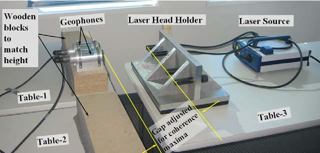
32 IR Stability standard and compact versions Two compact sensors provided to SLAC by PMD/eentec in March 2005 as a results of SBIR program. The size is 5*10*15cm, as requested in specification Tests in magnetic field have shown that there is no visible influence of high magnetic field on the MET sensors, so, they can be used as a prototype sensors for the IR region of ILC Case 4: horizontal anti-parallel Left: ap5 B=0T Right: ap5 B= -1T 32 May 3, 2005

33 33 May 3, 2005 Latest achievement: bond the 6-around- 1 cable in an even tighter bend radius; down to a bend radius of 3 cable diameters. BNL
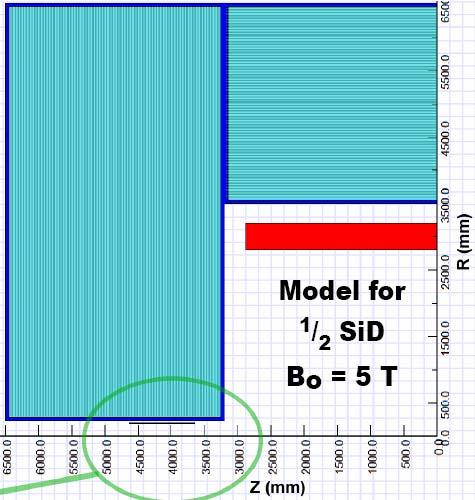
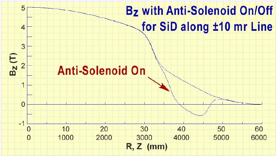
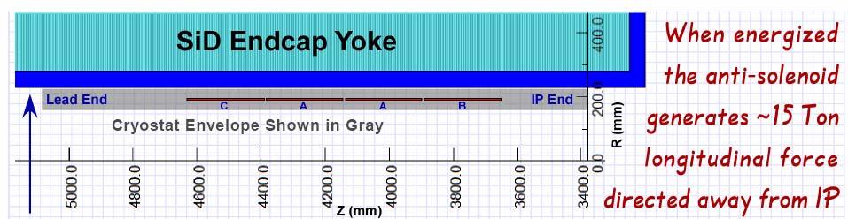
34 Antisolenoid and DID in SiD BNL-Fermilab- SLAC-UK-DESY 34 May 3, 2005

35 35 May 3, 2005 Detailed design of QD0, extraction quad, and antisolenoids BNL

36 36 May 3, 2005 Detailed comparison of 2omrad and 2mrad IR 20mrad extraction optics 2mrad extraction optics
37 Extraction line losses, 20 mrad Total loss, W Ideal collision at IP Max density (W/m) in SCQ / WQ/ bend/ drift 500 GeV nom. 0 0 / 0 / 0 / GeV high L / 49 / 42 / 31 1 TeV nom / 1.2 / 4.1 / TeV high L / 4025 / 2481 / 1352 Large vertical offset between beams at IP Total loss, W Max density (W/m) in SCQ / WQ/ bend/ drift / 0.42 / 0.12 / / 308 / 383 / / 106 / 79 / / 4968 / 8144 / Extraction line losses, 2 mrad (less detailed study) Ideal collision at IP Large vertical offset between beams at IP Loss (W) in QD0/QEXF1/Coll Loss (W) in QD0/QEXF1/Coll 500 GeV nom. 0 / 0 / ~ / 0 / ~ GeV high L ~250 / ~50 /? ~350 / ~400 /? 1 TeV nom. 0 / 0 /? 0 / 0 /? 1 TeV high L? /? /?? /? /? 37 May 3, 2005


38 Standard SLAC BSY Copper Protection Collimator Rated at 20 kw 38 May 3, 2005 Reference: The Stanford Two-Mile Accelerator, R. Neal, 1968 Vertical cooling passages drilled on either side of the gap and cooling loops around outside of the body 28 cm


39 Collimation and energy deposition studies 39 May 3, Halo ILC-FF9 β x *β y =6E5 m 2 IP Fermilab-SLAC- UK-DESY


40 Pre and post IP polarimeters & E-spectrometers 40 May 3, 2005


41 Gamma-gamma with nominal pars. 34 ILC optimistic: tracked = 121nm * 4.37 nm (geometrical is 87.6nm * 4.29nm ) ILC w/e+e- (at beta 3mm/0.3mm): tracked = 323nm * 5.21nm (geometrical is 247.6nm * 4.95nm) Correspondingly, the luminosity with tracked beams are: ILC optimistic: 8.48e+34 instead of 11.8e34 in the table, i.e. 72% ILC w/e+e- : 2.67e+34 instead of 5.9e34 in the table, i.e. 45% 41 May 3, 2005

42 42 May 3, 2005 ATF-2 at KEK ATF-2 would be BDS test Follow-on to FFTB New FFS optics Operational issues

43 43 May 3, 2005 BDS design and ATF-2 facility Many reasons to develop the ATF-2 Luminosity issues will be extremely challenging in the LC Likely more challenging than achieving the beam energy Complete FFTB studies FFTB never demonstrated routine operation of FFS Need to implement full feedback control and optimization Operate with ILC like bunch train and demonstrate IP feedback Operate with stable low emittance beam from ATF DR Provide demonstration and experience concurrent with ILC construction FFTB experience will be over 15 years old Train new generation of physicists Provide a visible test facility for project reviewers and sponsors
 Stabilization of beam center (B1) Down to < 2nm by nano-bpm (B2) Bunch-to-bunch feedback of ILC-like train 44 May 3,")
44 New final focus Configuration with bends to avoid crab-cavity test area ATF2 Goals & stages: (A) Small beam size (A1) Obtain σ y ~ 35nm (A2) Maintain for long time (B) Stabilization of beam center (B1) Down to < 2nm by nano-bpm (B2) Bunch-to-bunch feedback of ILC-like train 44 May 3, 2005


45 45 May 3, 2005 As ILC, ATF2 critically depends on instrumentation BSM to confirm 35nm beam size nano-bpm at IP to see the nm stability Laser-wire to tune the beam Cavity BPMs to measure the orbit Movers, active stabilization, alignment system Kickers to produce ILC-like train
46 46 May 3, 2005 Summary SLAC ILC program strong efforts on many fronts BDS design is making progress from the concept to optics, from optics to engineering design The worldwide BDS group is organizing its work There is a lot to do to arrive with a CDR with cost Arriving to baseline configuration at the end of 2005 require better organization of existing efforts Producing CDR with cost at the end of 2006 require increase of engineering support
SLAC ILC Accelerator R&D Program
 SLAC ILC Accelerator R&D Program SLUO Meeting September 26 th, 2005 Tor Raubenheimer SLAC 2005 ILC Program NLC group was redirected towards ILC Developed a program aimed at the topics identified in the
Focus of efforts. ILC 2010, Mar/27/10 A. Seryi, BDS: 2
 Beam Delivery System Updates Andrei Seryi for BDS design and ATF2 commissioning teams LCWS 2010 / ILC 2010 March 28, 2010 Plan of the program at ILC2010 Focus of efforts Work on parameter set for a possible
PEP II Design Outline
 PEP II Design Outline Balša Terzić Jefferson Lab Collider Review Retreat, February 24, 2010 Outline General Information Parameter list (and evolution), initial design, upgrades Collider Ring Layout, insertions,
L-Band RF R&D. SLAC DOE Review June 15 th, Chris Adolphsen SLAC
 L-Band RF R&D SLAC DOE Review June 15 th, 2005 Chris Adolphsen SLAC International Linear Collider (ILC) RF Unit (TESLA TDR Layout) Gradient = 23.4 MV/m Bunch Spacing = 337 ns Fill Time = 420 µs Train Length
WG2 Group Summary. Chris Adolphsen Terry Garvey Hitoshi Hayano
 WG2 Group Summary Chris Adolphsen Terry Garvey Hitoshi Hayano Linac Options Fest On Thursday afternoon, various experts summarized the linac baseline options. Although hard choices have yet to be made,
STATUS OF THE INTERNATIONAL LINEAR COLLIDER
 STATUS OF THE INTERNATIONAL LINEAR COLLIDER K. Yokoya, KEK, Tsukuba, Japan Abstract The International Linear Collider (ILC) is the nextgeneration electron-positron collider. Since the publication of the
SUMMARY OF THE ILC R&D AND DESIGN
 SUMMARY OF THE ILC R&D AND DESIGN B. C. Barish, California Institute of Technology, USA Abstract The International Linear Collider (ILC) is a linear electron-positron collider based on 1.3 GHz superconducting
Andrei Seryi, Toshiaki Tauchi. December 15-18, 2008
 ATF2 milestones for discussion Andrei Seryi, Toshiaki Tauchi December 15-18, 2008 7th ATF2 Project Meeting What are natural milestones for ATF2? ATF2 design: Nominal IP β y* =0.1 mm & L * =1 m this give
Overview of the X-band R&D Program
 Overview of the X-band R&D Program SLAC-PUB-9442 August 2002 Abstract T.O. Raubenheimer Stanford Linear Accelerator Center, Stanford University, Stanford, California 94309 USA An electron/positron linear
A Facility for Accelerator Physics and Test Beam Experiments
 A Facility for Accelerator Physics and Test Beam Experiments U.S. Department of Energy Review Roger Erickson for the FACET Design Team February 20, 2008 SLAC Overview with FACET FACET consists of four
Present Status and Future Upgrade of KEKB Injector Linac
 Present Status and Future Upgrade of KEKB Injector Linac Kazuro Furukawa, for e /e + Linac Group Present Status Upgrade in the Near Future R&D towards SuperKEKB 1 Machine Features Present Status and Future
Availability and Reliability Issues for the ILC
 Availability and Reliability Issues for the ILC SLAC Presented at PAC07 26 June 07 Contents Introduction and purpose of studies The availability simulation What was modeled (important assumptions) Some
Nick Walker DESY MAC
 Nick Walker DESY MAC 4.5.2006 XFEL X-Ray Free-Electron Laser DESY ILC Project Group Accelerator Experimentation Behnke, Elsen, Walker (chair) WP 15, 16 WP 4-7 Accelerator Physics and Design WP 6 High Gradient
Requirements for the Beam Abort Magnet and Dump
 Requirements for the Beam Abort Magnet and Dump A beam abort kicker (pulsed dipole magnet) and dump are required upbeam of the LCLS undulator in order to protect the undulator from mis-steered and poor
Development of beam-collision feedback systems for future lepton colliders. John Adams Institute for Accelerator Science, Oxford University
 Development of beam-collision feedback systems for future lepton colliders P.N. Burrows 1 John Adams Institute for Accelerator Science, Oxford University Denys Wilkinson Building, Keble Rd, Oxford, OX1
Status and Plans for PEP-II
 Status and Plans for PEP-II John Seeman SLAC Particle and Particle-Astrophysics DOE HEPAP P5 Review April 21, 2006 Topics Luminosity records for PEP-II in October 2005 Fall shut-down upgrades Run 5b turn
P. Emma, et al. LCLS Operations Lectures
 P. Emma, et al. LCLS Operations Lectures LCLS 1 LCLS Accelerator Schematic 6 MeV 135 MeV 250 MeV σ z 0.83 mm σ z 0.83 mm σ z 0.19 mm σ δ 0.05 % σ δ 0.10 % σ δ 1.6 % Linac-0 L =6 m rf gun L0-a,b Linac-1
PEP II STATUS AND PLANS *
 PEP II STATUS AND PLANS * John T. Seeman + Stanford Linear Accelerator Center, Stanford University, Stanford, CA 94309 USA The PEP II B-Factory 1 project is an e + e - colliding beam storage ring complex
NLC - The Next Linear Collider Project NLC R&D. D. L. Burke. DOE Annual Program Review SLAC April 9-11, 2003
 DOE Annual Program Review SLAC April 9-11, 2003 NLC Activities for the Past Year Accelerator Design centered around ILC-TRC studies. Technology R&D focused on the RF R&D. Modulator, klystron, SLED-II,
5 Project Costs and Schedule
 93 5 Project Costs and Schedule 5.1 Overview The cost evaluation for the integrated version of the XFEL with 30 experiments and 35 GeV beam energy as described in the TDR-2001 yielded 673 million EUR for
ILC Damping Ring Lattice Status Report. Louis Emery and Aimin Xiao Argonne National Laboratory Presented at KEK workshop Dec 18th, 2007
 Status Report Louis Emery and Aimin Xiao Argonne National Laboratory Presented at KEK workshop Dec 18th, 2007 Outline New 8-fold symmetric lattice on ILC Cornell wiki pages, as of 12/18/2007 Separated
Accelerator Instrumentation RD. Monday, July 14, 2003 Marc Ross
 Monday, Marc Ross Linear Collider RD Most RD funds address the most serious cost driver energy The most serious impact of the late technology choice is the failure to adequately address luminosity RD issues
3 cerl. 3-1 cerl Overview. 3-2 High-brightness DC Photocathode Gun and Gun Test Beamline
 3 cerl 3-1 cerl Overview As described before, the aim of the cerl in the R&D program includes the development of critical components for the ERL, as well as the construction of a test accelerator. The
INFN School on Electron Accelerators. RF Power Sources and Distribution
 INFN School on Electron Accelerators 12-14 September 2007, INFN Sezione di Pisa Lecture 7b RF Power Sources and Distribution Carlo Pagani University of Milano INFN Milano-LASA & GDE The ILC Double Tunnel
Experience with the Cornell ERL Injector SRF Cryomodule during High Beam Current Operation
 Experience with the Cornell ERL Injector SRF Cryomodule during High Beam Current Operation Matthias Liepe Assistant Professor of Physics Cornell University Experience with the Cornell ERL Injector SRF
FINAL DESIGN OF ILC RTML EXTRACTION LINE FOR SINGLE STAGE BUNCH COMPRESSOR
 BNL-94942-2011-CP FINAL DESIGN OF ILC RTML EXTRACTION LINE FOR SINGLE STAGE BUNCH COMPRESSOR S. Sletskiy and N. Solyak Presented at the 2011 Particle Accelerator Conference (PAC 11) New York, NY March
PEP-II STATUS REPORT *
 PEP-II STATUS REPORT * Jonathan Dorfan Stanford Linear Accelerator Center, Stanford University, Stanford, CA 94309 USA For the SLAC, LBNL, LLNL PEP-II group Abstract The main design features of the PEP-II
PEP II Status and Plans
 SLAC-PUB-6854 September 1998 PEP II Status and Plans By John T. Seeman Invited talk presented at the 16th IEEE Particle Accelerator Conference (PAC 95) and International Conference on High Energy Accelerators,
SPEAR 3: Operations Update and Impact of Top-Off Injection
 SPEAR 3: Operations Update and Impact of Top-Off Injection R. Hettel for the SSRL ASD 2005 SSRL Users Meeting October 18, 2005 SPEAR 3 Operations Update and Development Plans Highlights of 2005 SPEAR 3
Detailed Design Report
 Detailed Design Report Chapter 4 MAX IV Injector 4.6. Acceleration MAX IV Facility CHAPTER 4.6. ACCELERATION 1(10) 4.6. Acceleration 4.6. Acceleration...2 4.6.1. RF Units... 2 4.6.2. Accelerator Units...
Diamond RF Status (RF Activities at Daresbury) Mike Dykes
 Mike Dykes") Diamond RF Status (RF Activities at Daresbury) Mike Dykes ASTeC What is it? What does it do? Diamond Status Linac Booster RF Storage Ring RF Summary Content ASTeC ASTeC was formed in 2001 as a centre of
Diamond RF Status (RF Activities at Daresbury) Mike Dykes ASTeC What is it? What does it do? Diamond Status Linac Booster RF Storage Ring RF Summary Content ASTeC ASTeC was formed in 2001 as a centre of
THE NEXT LINEAR COLLIDER TEST ACCELERATOR: STATUS AND RESULTS * Abstract
 SLAC PUB 7246 June 996 THE NEXT LINEAR COLLIDER TEST ACCELERATOR: STATUS AND RESULTS * Ronald D. Ruth, SLAC, Stanford, CA, USA Abstract At SLAC, we are pursuing the design of a Next Linear Collider (NLC)
Digital BPMs and Orbit Feedback Systems
 Digital BPMs and Orbit Feedback Systems, M. Böge, M. Dehler, B. Keil, P. Pollet, V. Schlott Outline stability requirements at SLS storage ring digital beam position monitors (DBPM) SLS global fast orbit
Design Studies For The LCLS 120 Hz RF Gun Injector
 BNL-67922 Informal Report LCLS-TN-01-3 Design Studies For The LCLS 120 Hz RF Gun Injector X.J. Wang, M. Babzien, I. Ben-Zvi, X.Y. Chang, S. Pjerov, and M. Woodle National Synchrotron Light Source Brookhaven
Oak Ridge Spallation Neutron Source Proton Power Upgrade Project and Second Target Station Project
 Oak Ridge Spallation Neutron Source Proton Power Upgrade Project and Second Target Station Project Workshop on the future and next generation capabilities of accelerator driven neutron and muon sources
SLAC X-band Technology R&D. Tor Raubenheimer DOE Briefing June 11 th, 2010
 SLAC X-band Technology R&D Tor Raubenheimer DOE Briefing June 11 th, 2010 Introduction Overall ARD strategy ILC Program X-band program Compact XFEL and other applications Status and development needs Proposed
Precision measurements of beam current, position and phase for an e+e- linear collider
 Precision measurements of beam current, position and phase for an e+e- linear collider R. Corsini on behalf of H. Braun, M. Gasior, S. Livesley, P. Odier, J. Sladen, L. Soby INTRODUCTION Commissioning
Suggested ILC Beam Parameter Range Rev. 2/28/05 Tor Raubenheimer
 The machine parameters and the luminosity goals of the ILC were discussed at the 1 st ILC Workshop. In particular, Nick Walker noted that the TESLA machine parameters had been chosen to achieve a high
PEP-II IR-2 Alignment
 SLAC-PUB-10328 January 2004 PEP-II IR-2 Alignment A. Seryi, S. Ecklund, C. Le Cocq, R. Pushor, R. Ruland, Z. Wolf SLAC, Stanford, CA 94025, USA This paper describes the first results and preliminary analysis
Overview of NLC/JLC Collaboration *
 SLAC PUB 10117 August 2002 Overview of NLC/JLC Collaboration * K. Takata KEK, Oho, Tsukuba-shi 305-0801, JAPAN On behalf of the NLC Group Stanford Linear Accelerator Center, Stanford, California 94309,
ATF2 project in the ATF international collaboration, including coordination issues
 ATF2 project in the ATF international collaboration, including coordination issues 1. Status of ATF collaboration 2. R&D items in ATF 3. Schedule 4. Expectation Junji Urakawa, KEK ATF2-IN2P3-KEK kick-off
LCLS Injector Technical Review
 LCLS Injector Technical Review Stanford Linear Accelerator Center November 3&4 2003 Review Committee Members: Prof. Patrick O Shea Chair University of Maryland Dr. E. Colby Stanford Linear Accelerator
Summary of the 1 st Beam Line Review Meeting Injector ( )
") Summary of the 1 st Beam Line Review Meeting Injector (23.10.2006) 15.11.2006 Review the status of: beam dynamics understanding and simulations completeness of beam line description conceptual design of
Summary of the 1 st Beam Line Review Meeting Injector (23.10.2006) 15.11.2006 Review the status of: beam dynamics understanding and simulations completeness of beam line description conceptual design of
SABER A Facility for Accelerator Physics and Test Beam Experiments Roger Erickson SABER Workshop March 15, 2006
 SABER A Facility for Accelerator Physics and Test Beam Experiments Roger Erickson SABER Workshop March 15, 2006 FFTB will soon be gone! The Problem: On April 10, 2006, the Final Focus Test Beam (FFTB)
Beam-based Feedback Systems
 Beam-based Feedback Systems Philip Burrows Queen Mary, University of London ILC Beam-based Feedback/Feedforward Systems Intra-train (bunch-bunch) feedback at IP: 3 MHz Pulse-pulse feedback at IP: 5 Hz
2 Work Package and Work Unit descriptions. 2.8 WP8: RF Systems (R. Ruber, Uppsala)
") 2 Work Package and Work Unit descriptions 2.8 WP8: RF Systems (R. Ruber, Uppsala) The RF systems work package (WP) addresses the design and development of the RF power generation, control and distribution
2 Work Package and Work Unit descriptions 2.8 WP8: RF Systems (R. Ruber, Uppsala) The RF systems work package (WP) addresses the design and development of the RF power generation, control and distribution
High Brightness Injector Development and ERL Planning at Cornell. Charlie Sinclair Cornell University Laboratory for Elementary-Particle Physics
 High Brightness Injector Development and ERL Planning at Cornell Charlie Sinclair Cornell University Laboratory for Elementary-Particle Physics June 22, 2006 JLab CASA Seminar 2 Background During 2000-2001,
Activities on FEL Development and Application at Kyoto University
 Activities on FEL Development and Application at Kyoto University China-Korea-Japan Joint Workshop on Electron / Photon Sources and Applications Dec. 2-3, 2010 @ SINAP, Shanghai Kai Masuda Inst. Advanced
Status of Elettra, top-up and other upgrades
 Status of Elettra, top-up and other upgrades Emanuel Karantzoulis ELETTRA / Trieste, Italy / 2010 November 25-26 Past and Present Configurations 1994-2007 From 2008 No full energy injection Full energy
CONSTRUCTION AND COMMISSIONING OF BEPCII
 Abstract CONSTRUCTION AND COMMISSIONING OF BEPCII C. Zhang, J.Q. Wang, L. Ma and G.X.Pei for the BEPCII Team, IHEP, CAS P.O.Box 918, Beijing 100049, China BEPCII is the major upgrade of BEPC (Beijing Electron-
LHC Beam Instrumentation Further Discussion
 LHC Beam Instrumentation Further Discussion LHC Machine Advisory Committee 9 th December 2005 Rhodri Jones (CERN AB/BDI) Possible Discussion Topics Open Questions Tune measurement base band tune & 50Hz
Status of CTF3. G.Geschonke CERN, AB
 Status of CTF3 G.Geschonke CERN, AB CTF3 layout CTF3 - Test of Drive Beam Generation, Acceleration & RF Multiplication by a factor 10 Drive Beam Injector ~ 50 m 3.5 A - 2100 b of 2.33 nc 150 MeV - 1.4
November 5,1999. The NLC Injector UCRL-JC
 Preprint UCRL-JC-13-6450 The NLC Injector System V. Bharadwaj, J.E. Clendenin, P. Emma, J. Frisch, R.K. Jobe, T. Kotseroglou, P. Krejcik, A. V. Kulikov, Z. Li, T. Maruyama, K.K. Millage, B. McKee, G. Mulhollan,
TITLE PAGE. Title of paper: PUSH-PULL FEL, A NEW ERL CONCEPT Author: Andrew Hutton. Author Affiliation: Jefferson Lab. Requested Proceedings:
 TITLE PAGE Title of paper: PUSH-PULL FEL, A NEW ERL CONCEPT Author: Andrew Hutton Author Affiliation: Jefferson Lab Requested Proceedings: Unique Session ID: Classification Codes: Keywords: Energy Recovery,
Modulator Overview System Design vs. Tunnel Topologies. Snowmass Workshop August 16, 2005 Ray Larsen for the SLAC ILC Group
 Modulator Overview System Design vs. Tunnel Topologies Snowmass Workshop August 16, 2005 Ray Larsen for the SLAC ILC Group Outline! I. Modulator Options vs. Topologies! II. Preliminary Cost Estimates!
Top-Up Experience at SPEAR3
 Top-Up Experience at SPEAR3 Contents SPEAR 3 and the injector Top-up requirements Hardware systems and modifications Safety systems & injected beam tracking Interlocks & Diagnostics SPEAR3 Accelerator
4.4 Injector Linear Accelerator
 4.4 Injector Linear Accelerator 100 MeV S-band linear accelerator based on the components already built for the S-Band Linear Collider Test Facility at DESY [1, 2] will be used as an injector for the CANDLE
PROJECT DESCRIPTION. Longitudinal phase space monitors for the ILC injectors and bunch compressors
 PROJECT DESCRIPTION Longitudinal phase space monitors for the ILC injectors and bunch compressors Personnel and Institution(s) requesting funding Philippe Piot Northern Illinois University Dept of Physics,
RF plans for ESS. Morten Jensen. ESLS-RF 2013 Berlin
 RF plans for ESS Morten Jensen ESLS-RF 2013 Berlin Overview The European Spallation Source (ESS) will house the most powerful proton linac ever built. The average beam power will be 5 MW which is five
STATUS OF THE SWISSFEL C-BAND LINEAR ACCELERATOR
 Proceedings of FEL213, New York, NY, USA STATUS OF THE SWISSFEL C-BAND LINEAR ACCELERATOR F. Loehl, J. Alex, H. Blumer, M. Bopp, H. Braun, A. Citterio, U. Ellenberger, H. Fitze, H. Joehri, T. Kleeb, L.
RF considerations for SwissFEL
 RF considerations for H. Fitze in behalf of the PSI RF group Workshop on Compact X-Ray Free Electron Lasers 19.-21. July 2010, Shanghai Agenda Introduction RF-Gun Development C-band development Summary
Linac 4 Instrumentation K.Hanke CERN
 Linac 4 Instrumentation K.Hanke CERN CERN Linac 4 PS2 (2016?) SPL (2015?) Linac4 (2012) Linac4 will first inject into the PSB and then can be the first element of a new LHC injector chain. It will increase
DESIGN AND PERFORMANCE OF L-BAND AND S-BAND MULTI BEAM KLYSTRONS
 DESIGN AND PERFORMANCE OF L-BAND AND S-BAND MULTI BEAM KLYSTRONS Y. H. Chin, KEK, Tsukuba, Japan. Abstract Recently, there has been a rising international interest in multi-beam klystrons (MBK) in the
Working Group 2 Introductory presentation. Convenors C. Adolphsen, T. Garvey, H. Hayano
 Working Group 2 Introductory presentation. Convenors C. Adolphsen, T. Garvey, H. Hayano Topics covered by WG2 Modulators / klystrons RF wave-guide distribution Low Level RF Beam interfaces (quadrupoles,
PEP-II Overview & Ramp Down Plan. J. Seeman DOE PEP-II Ramp Down-D&D Review August 6-7, 2007
 PEP-II Overview & Ramp Down Plan J. Seeman DOE PEP-II Ramp Down-D&D Review August 6-7, 2007 Topics Overview of the PEP-II Collider PEP-II turns off September 30, 2008. General list of components and buildings
XFEL High Power RF System Recent Developments
 XFEL High Power RF System Recent Developments for the XFEL RF Group Outline XFEL RF System Requirements Overview Basic Layout RF System Main Components Multibeam Klystrons Modulator RF Waveguide Distribution
PULSED POWER FOR FUTURE LINEAR ACCELERATORS
 PULSED POWER FOR FUTURE LINEAR ACCELERATORS Peter D. Pearce High-energy accelerators High-energy accelerators enable us to collide particle beams together and create conditions believed to be similar to
LEP OPERATION AND PERFORMANCE WITH ELECTRON-POSITRON COLLISIONS AT 209 GEV
 LEP OPERATION AND PERFORMANCE WITH ELECTRON-POSITRON COLLISIONS AT 29 GEV R. W. Aßmann, CERN, Geneva, Switzerland Abstract The Large Electron-Positron Collider (LEP) at CERN completed its operation in
Electron Bypass Line (EBL) Design Electrons to A-line bypassing LCLS T. Fieguth, R. Arnold
 Design Electrons to A-line bypassing LCLS T. Fieguth, R. Arnold") September 2007 SLAC-TN-08-001 Electron Bypass Line (EBL) Design Electrons to A-line bypassing LCLS T. Fieguth, R. Arnold Introduction Forty one years ago, September 20, 1966, the first beam entered End
September 2007 SLAC-TN-08-001 Electron Bypass Line (EBL) Design Electrons to A-line bypassing LCLS T. Fieguth, R. Arnold Introduction Forty one years ago, September 20, 1966, the first beam entered End
Week 0: PPS Certification and Processing. Mon Feb 11 Tue Feb 12 Wed Feb 13 Thu Feb 14 Fri Feb 15 Sat Feb 16 Sun Feb 17
 Week 0: PPS Certification and Processing Mon Feb 11 Tue Feb 12 Wed Feb 13 Thu Feb 14 Fri Feb 15 Sat Feb 16 Sun Feb 17 Work in tunnel Work in tunnel PPS Certification PPS Certification PPS Certification
Beam Losses During LCLS Injector Phase-1 1 Operation
 Beam Losses During LCLS Injector Phase-1 1 Operation & Paul Emma September 28, 2006 Radiation Safety Committee Review Scope of Phase 1 Operation Request for Three Operating Modes Operating Plan for Phase
SLAC R&D Program for a Polarized RF Gun
 ILC @ SLAC R&D Program for a Polarized RF Gun SLAC-PUB-11657 January 2006 (A) J. E. CLENDENIN, A. BRACHMANN, D. H. DOWELL, E. L. GARWIN, K. IOAKEIMIDI, R. E. KIRBY, T. MARUYAMA, R. A. MILLER, C. Y. PRESCOTT,
The LEP Superconducting RF System
 The LEP Superconducting RF System K. Hübner* for the LEP RF Group CERN The basic components and the layout of the LEP rf system for the year 2000 are presented. The superconducting system consisted of
reported by T. Shintake KEK / RIKEN Japan Summary of C-band R&D for Linear Collider at KEK New soft-x-ray FEL Project at RIKEN/SPring-8
 C-band RF System R&D reported by T. Shintake KEK / RIKEN Japan Summary of C-band R&D for Linear Collider at KEK New soft-x-ray FEL Project at RIKEN/SPring-8 Project was funded in 2001 April Material Science
2008 JINST 3 S LHC Machine THE CERN LARGE HADRON COLLIDER: ACCELERATOR AND EXPERIMENTS. Lyndon Evans 1 and Philip Bryant (editors) 2
 2") PUBLISHED BY INSTITUTE OF PHYSICS PUBLISHING AND SISSA RECEIVED: January 14, 2007 REVISED: June 3, 2008 ACCEPTED: June 23, 2008 PUBLISHED: August 14, 2008 THE CERN LARGE HADRON COLLIDER: ACCELERATOR AND
PUBLISHED BY INSTITUTE OF PHYSICS PUBLISHING AND SISSA RECEIVED: January 14, 2007 REVISED: June 3, 2008 ACCEPTED: June 23, 2008 PUBLISHED: August 14, 2008 THE CERN LARGE HADRON COLLIDER: ACCELERATOR AND
ILC RF System R&D. Chris Adolphsen, SLAC. Section of 1.3 GHz SC Linac. June 29, 2007 PAC07 Talk FRYC01
 ILC RF System R&D Chris Adolphsen, SLAC June 29, 2007 PAC07 Talk FRYC01 Section of 1.3 GHz SC Linac ILC Main Linac RF Unit (1 of 560) RF System Gradient = 31.5 MV/m Rep Rate = 5 Hz Beam Current = 9.0 ma
Current status of XFEL/SPring-8 project and SCSS test accelerator
 Current status of XFEL/SPring-8 project and SCSS test accelerator Takahiro Inagaki for XFEL project in SPring-8 inagaki@spring8.or.jp Outline (1) Introduction (2) Key technology for compactness (3) Key
Development of an Abort Gap Monitor for High-Energy Proton Rings *
 Development of an Abort Gap Monitor for High-Energy Proton Rings * J.-F. Beche, J. Byrd, S. De Santis, P. Denes, M. Placidi, W. Turner, M. Zolotorev Lawrence Berkeley National Laboratory, Berkeley, USA
Evaluation of Performance, Reliability, and Risk for High Peak Power RF Sources from S-band through X-band for Advanced Accelerator Applications
 Evaluation of Performance, Reliability, and Risk for High Peak Power RF Sources from S-band through X-band for Advanced Accelerator Applications Michael V. Fazio C. Adolphsen, A. Jensen, C. Pearson, D.
The Elettra Storage Ring and Top-Up Operation
 The Elettra Storage Ring and Top-Up Operation Emanuel Karantzoulis Past and Present Configurations 1994-2007 From 2008 5000 hours /year to the users 2010: Operations transition year Decay mode, 2 GeV (340mA)
STATUS AND FUTURE PROSPECTS OF CLIC
 STATUS AND FUTURE PROSPECTS OF CLIC S. Döbert, for the CLIC/CTF3 collaboration, CERN, Geneva, Switzerland Abstract The Compact Linear Collider (CLIC) is studied by a growing international collaboration.
30 GHz Power Production / Beam Line
 30 GHz Power Production / Beam Line Motivation & Requirements Layout Power mode operation vs. nominal parameters Beam optics Achieved performance Problems Beam phase switch for 30 GHz pulse compression
The ESS Accelerator. For Norwegian Industry and Research. Oslo, 24 Sept Håkan Danared Deputy Head Accelerator Division Group Leader Beam Physics
 The ESS Accelerator For Norwegian Industry and Research Oslo, 24 Sept 2013 Håkan Danared Deputy Head Accelerator Division Group Leader Beam Physics The Hadron Intensity Frontier Courtesy of M. Seidel (PSI)
Status of RF Power and Acceleration of the MAX IV - LINAC
 Status of RF Power and Acceleration of the MAX IV - LINAC Dionis Kumbaro ESLS RF Workshop 2015 MAX IV Laboratory A National Laboratory for synchrotron radiation at Lunds University 1981 MAX-lab is formed
FIRST SIMULTANEOUS TOP-UP OPERATION OF THREE DIFFERENT RINGS IN KEK INJECTOR LINAC
 FIRST SIMULTANEOUS TOP-UP OPERATION OF THREE DIFFERENT RINGS IN KEK INJECTOR LINAC M. Satoh #, for the IUC * Accelerator Laboratory, High Energy Accelerator Research Organization (KEK) 1-1 Oho, Tsukuba,
Development of Multiple Beam Guns for High Power RF Sources for Accelerators and Colliders
 SLAC-PUB-10704 Development of Multiple Beam Guns for High Power RF Sources for Accelerators and Colliders R. Lawrence Ives*, George Miram*, Anatoly Krasnykh @, Valentin Ivanov @, David Marsden*, Max Mizuhara*,
!"!3
 Abstract A single-mode 500 MHz superconducting cavity cryomodule has been developed at Cornell for the electronpositron collider/synchrotron light source CESR. The Cornell B-cell cavity belongs to the
CLIC Feasibility Demonstration at CTF3
 CLIC Feasibility Demonstration at CTF3 Roger Ruber Uppsala University, Sweden, for the CLIC/CTF3 Collaboration http://cern.ch/clic-study LINAC 10 MO303 13 Sep 2010 The Key to CLIC Efficiency NC Linac for
TWO BUNCHES WITH NS-SEPARATION WITH LCLS*
 TWO BUNCHES WITH NS-SEPARATION WITH LCLS* F.-J. Decker, S. Gilevich, Z. Huang, H. Loos, A. Marinelli, C.A. Stan, J.L. Turner, Z. van Hoover, S. Vetter, SLAC, Menlo Park, CA 94025, USA Abstract The Linac
Future Circular Collider Study
 Status and Progress M. Benedikt, F. Zimmermann gratefully acknowledging input from FCC coordination group global design study team and all other contributors LHC SPS PS FCC http://cern.ch/fcc Work supported
Upgrading LHC Luminosity
 1 Upgrading LHC Luminosity 2 Luminosity (cm -2 s -1 ) Present (2011) ~2 x10 33 Beam intensity @ injection (*) Nominal (2015?) 1 x 10 34 1.1 x10 11 Upgraded (2021?) ~5 x10 34 ~2.4 x10 11 (*) protons per
45 MW, 22.8 GHz Second-Harmonic Multiplier for High-Gradient Tests*
 US High Gradient Research Collaboration Workshop. SLAC, May 23-25, 2007 45 MW, 22.8 GHz Second-Harmonic Multiplier for High-Gradient Tests* V.P. Yakovlev 1, S.Yu. Kazakov 1,2, and J.L. Hirshfield 1,3 1
ATF Energy Spectrometer Experiments
 ATF Energy Spectrometer Experiments Mike Hildreth representing Energy Spectrometer Enthusiasts ATF Basics 6 BPMs (3 per side) separated by 3?m LLNL (passive) girder KEK (active) girder Ultimate Goal: Measurement
Beam Instrumentation for CTF3 and CLIC
 Beam Instrumentation for CTF3 and CLIC Beam loss - Beam halo monitoring developments CLIC diagnostic Common developments with other projects Specific requirements for CLIC Beam Loss and Beam Halo measurement
J/NLC Progress on R1 and R2 Issues. Chris Adolphsen
 J/NLC Progress on R1 and R2 Issues Chris Adolphsen Charge to the International Linear Collider Technical Review Committee (ILC-TRC) To assess the present technical status of the four LC designs at hand,
Status of SOLARIS Arkadiusz Kisiel
 Status of SOLARIS Arkadiusz Kisiel Solaris National Synchrotron Light Source Jagiellonian University Czerwone Maki 98 30-392 Kraków www.synchrotron.uj.edu.pl Arkadiusz.Kisiel@uj.edu.pl On behalf of SOLARIS
LCLS RF Reference and Control R. Akre Last Update Sector 0 RF and Timing Systems
 LCLS RF Reference and Control R. Akre Last Update 5-19-04 Sector 0 RF and Timing Systems The reference system for the RF and timing starts at the 476MHz Master Oscillator, figure 1. Figure 1. Front end
ATF2 COMMISSIONING. IP β x/y, mm 4 / / 0.4 IP η, rad σ E, % ~0.1 ~0.1
 ATF2 COMMISSIONING SLAC-PUB-13765 A. Seryi # (SLAC), G. Christian (ATOMKI, Debrecen), B. Parker (BNL), D. Schulte, J.-P. Delahaye, R. Tomas, F. Zimmermann (CERN), A. Wolski (Cockcroft Inst.), E. Elsen
DESIGN OF 1.2-GEV SCL AS NEW INJECTOR FOR THE BNL AGS*
 DESIGN OF 1.2-GEV SCL AS NEW INJECTOR FOR THE BNL AGS* A. G. Ruggiero, J. Alessi, M. Harrison, M. Iarocci, T. Nehring, D. Raparia, T. Roser, J. Tuozzolo, W. Weng. Brookhaven National Laboratory, PO Box
SRF-gun Development Overview. J. Sekutowicz 17 th September, 2015 SRF15, Whistler, Canada
 SRF-gun Development Overview J. Sekutowicz 17 th September, 2015 SRF15, Whistler, Canada Acknowledgment Many thanks to: A. Arnold, J. Hao, E. Kako, T. Konomi, D. Kostin, J. Lorkiewicz, A. Neumann, J. Teichert