VersaCap Lighting System
|
|
|
- Ashlynn Gregory
- 5 years ago
- Views:
Transcription


1 VersaCap Lighting System Installation Instructions For Single Universe Lighting Systems Manual Version: V1.1 DFX 465 Taunton Avenue, Suite 108, West Berlin, NJ All brand names, product names and trademarks are property of their owners. Specifications subject to change without notice.
, G(green), B(blue) LEDs, signal converters and a key pad controller.")


2 Introduction The Versa Cap LED Lane Cap Lighting System is a high output LED lighting system that provides effects lighting on small gutter capping for each bowling lanes. The system uses LED light strips with R(red), G(green), B(blue) LEDs, signal converters and a key pad controller. System Includes The VersaCap lighting system includes: LED light strips, pre-programmed key pad controller, control cables, pre-programmed signal converters, mounting track, impact resistance protective covers, power and control cables. Signal Converter The signal converter provides the control signal to the LED strips. The signal converters have been preaddressed so do not change the setting. Power Supply The power supply is a 12V power supply that accommodates input voltages ranging from 100 VAC to 240 VAC. It connects to the converter and a electrical power outlet. The LED lane power supplies are line voltage volt 50/60Hz to 12v DC to the signal converter. Key Pad Controller Key pad lighting controller with pre-programmed shows. LED Strip The LED Strip is includes red, green and blue LEDs. It is powered and operated by the signal converter. Starter Track The starter track is the first piece of track to be installed at the foul. This track has a small opening to for the power cable connector. The opening must be install closest to the foul line. Track The track is used to mount the LED strip and as a conduit for the power cable. Cover The high strength cover is installed on the track and used to protect the LED strip and track. Power Cable Provides power to the foul line end of the LED strip. DMX Signal Cable DMX data cable with bare tails. 2
3 Installation of the System 1. Mount Track A. Mount the 48 track to the top of the small capping on the bowling lanes. B. Start at the beginning of the lanes by the foul line and work your way towards the pins. C. Center a piece of Starter Track at the beginning of the small capping with the opening for the power connector to the foul line. Start at the beginning at the small cap not the bull-nose of the cap. D. Use three.75" screws to attached the track to the capping. Screw through the opening in the track so the screw head pulls through the first layer of the track and into the capping. This will secure the track. Place screws at the beginning about an inch from the end, middle and at the end at about an inch from the end. Be sure not to over tighten the screws. E. Continue mounting the track the length of the capping and stop at the masking unit or scoring reflector. Generally, each lane takes about 15 pieces of track. It may be necessary to cut the last piece of track to size. We recommend installing the track up to the masking unit leg since the control wires will be attached to the masking unit leg and run up to the control equipment mounted on the curtain wall. F. Move to the next lane. 2. Install The LED Strip Power Cable A. The LED strip power cable is the white, seventy-five foot cable with this connector on one end. B. Starting with the connector in the opening of the Stater Track by the foul line, push the cable through the center of the track into the groove. C. Continue feeding the cable through the track until you get to the end of the track by the masking unit. 3. Install LED Lighting Strips WARNING! DO NOT step or walk on the LED light strips!!! A. Remove the light strings from the packing B. Unroll the light string and stretch out the strip the length of the lane. The end of the LED strip with the power connector starts at the foul line. Be careful not to bend the LED strip. C. Place the entire LED strip into the top pf the track. D. Plug the LED strip and the power cable connectors together connector at the foul line. E. Slide the power connection into the power connector of the power cable at opening of the starter track near the foul line. F. Press the cable of the LED strip into the track. G. Line up and center the LED strip in the track. At the beginning of the LED strip, gently fold the LED strip over and hold it as flat and straight as possible and centered in the track. At the beginning of the LED Strip, begin to remove the tape backing from the back of the LED strip and gently press the strip in to place. The track and LED strip should look like this when finished. 3
4 Installation of the System 4. Install LED Lighting Strips Continued. D. Continue with the LED strip the rest of the length of the strip. E. At the masking unit leg; secure the LED light cables to the masking unit leg with tie wraps. F. Be sure the cable is secure and away from the path of any bowling ball. 5. Leader Control Cables A. The leader cable is used to extend the control and power from the converter to the light strip. B. Connect the leader cable to the converter and secure the cable with tie wraps. C. Continue running the leader cable to the converter. 6. Install LED Strip Protective Covers A. The protective covers are use to protect the LED lights from bowling balls. B. Start at the foul line end of the light strip. C. Carefully slide the cover over the strip and mounting track. (It is also possible to snap the covers over the lighting strips and track.) D. Slide the cover down the track towards the masking unit and stop at the end of the track. E. Then continuing with installing additional covers. It is possible to slide more than one cover down the lane at a time. Stop adding covers when the light string and track are completely covered. It may will be necessary to cut the last protective cover to size for each lane. F. If the light string and leader cables are not secured and covered by the protective cover at the masking unit; add track and covers cut to size to secure them. 7. Install The Signal Converter A. The signal converter provides the control signal and power to the LED strips. B. The signal converter has been pre-addressed, so do not change the setting. C. Mount the signal converter to the curtain wall next to the power supply on the pinsetter curtain wall with two screws. D. Connect the power cable from the LED strip to the signal converter. This cable is green, red & white. E. Connector the signal cable from the LED strip to the output of the signal converter. 8. Install The Power Supply A. The power supply is used to provide power to the signal converter. B. Remove the power supply from the packaging. C. Install the provided IEC power tail in to the power supply. D. Mount the power supply next to the signal converter on the pinsetter side of the curtain wall with screws. E. Connect the power leads from the power supply to the signal converter. F. Be sure to secure and dress all cables on the back side of the curtain wall. Failure to do so can 4 result in cables damaged by moving parts.
5 10. Key Pad Lighting Controller A. The light controller is generally installed at the customer service desk or at any location you desire. Once at the desired location remove the key pad lighting controller from its packaging. B. If the key pad is to wall mounted; install old work low voltage single gang wall box in to the wall and pull the lighting control cable through the wall box. C. Then connect the power supply to the key pad controller. D. Connect the lighting control cable from the first signal converter on the curtain wall to the key pad controller. See Figure 1 for connecting signal cables to the key pad. E. Then mount the key pad to the wall box. F. Plug the power supply into an electrical outlet. G. Connect the other end of the cable to the DMX input of the first signal converter. See Figure 2 for more information. 11. Install the DMX Signal Cables Between The Signal Converters A. After all signal converters are mounted to the curtain wall and the main control cable has been installed from the key pad to the first signal converter, install the DMX signal cables between the signal converters. B. Starting with the first signal converter with the key pad controller cable connect the DMX signal input. Install one DMX signal cable into the DMX signal output of the first signal converter. Then connect the other end of the cable to the next signal converter to the DMX signal input. C. Use wire ties to secure all of the DMX signal cables to the curtain wall. D. Continue connecting or daisy chaining all of the DMX signal cables to the signal converters. See Figure 2 for more information. WARNING!!!! Make sure all power and data cables are secure and away from any moving parts of the pinsetter and away from the path of the bowling balls before turning on the VersaCap lighting or the bowling equipment. 12. Test The Lighting System A. After all of the components and cables have been installed and properly secured power on the VersaCap lighting system. B. Press one of the playbacks of the key pad and test the lighting system to be sure everything is working properly. See Figure 4 for a list of the light shows. Press one of the playback buttons here. 5
6 C. Speed settings can be changed on the controller by pressing the speed plus or minus buttons. D. We do not recommend using the intensity adjustments on the key pad. These have been set during the system programming. Key Pad Lighting Controller Show List 1. Slow color change 2. Medium color change 3. Fast color change 4. Rainbow slow 5. Rainbow medium 6. Random 7. Color bars 8. Red tones 9. Blue tones 10. Green tones Trouble Shooting The System If the system does not work correctly; trouble shoot the issue: 1. Make sure all of the connections are properly made. 2. Make sure all of the power supplies and key pad have electrical power. 3. All LED strips should perform the same patterns at the same time. If one or more strips are not working correctly; a) check the output wiring at the key pad. Make sure it is wire correctly. b) Then check the DMX data correction at the first signal converter. c) Then check the settings of the signal converters. These are also pre-programmed so we do not recommend changes unless the settings are not correct. Please see Figure 3 for more information. 4. If you need additional help please contact technical support & service at FOR MORE INFORMATION PLEASE VISIT: DFX All rights reserved. 6


7 Figure 1 To first signal converter 7


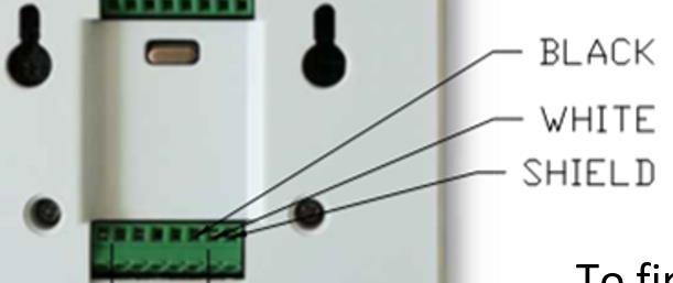
8 Figure 2 DMX Connections To The Signal Converter Black White Shield Black Shield White 8

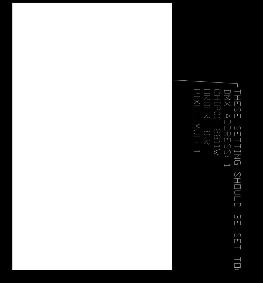
9 Figure 3 9
10 Figure 4 Key Pad Lighting Controller Show List 1. Slow color change 2. Medium color change 3. Fast color change 4. Rainbow slow 5. Rainbow medium 6. Random 7. Color bars 8. Red tones 9. Blue tones 10. Green tones 1 0
32 LCD Overhead Video Display Support Specifications (No Electrical required on rear curtain wall)
") 32 LCD Overhead Video Display Support Specifications (No Electrical required on rear curtain wall) NOTE: All of these documents are in PDF format located at www.steltronicusa.com To install the 32 LCD
32 LCD Overhead Video Display Support Specifications (No Electrical required on rear curtain wall) NOTE: All of these documents are in PDF format located at www.steltronicusa.com To install the 32 LCD
42 LCD Overhead Video Display Support Specifications (No Electrical required on rear curtain wall)
") 42 LCD Overhead Video Display Support Specifications (No Electrical required on rear curtain wall) NOTE: All of these documents are in PDF format located at www.steltronicusa.com To install the 42 LCD
42 LCD Overhead Video Display Support Specifications (No Electrical required on rear curtain wall) NOTE: All of these documents are in PDF format located at www.steltronicusa.com To install the 42 LCD
Specifications. End-Point Linearity - ±5% F.S., when used with HACO SCR-speed control
 Specifications Model 552 Catalog No. Model Power 55-0665 552 115 VAC, 50-60 Hz 55-0673 552A 230 VAC, 50-60 Hz Input - Single-ended, DC coupled 0 to +10V. Signal source can be Floating (not referenced to
42 LCD Overhead Video Display Support Specifications Electricity required on the rear curtain wall
 42 LCD Overhead Video Display Support Specifications Electricity required on the rear curtain wall NOTE: All of these documents are in PDF format located at www.steltronicusa.com To install the 42 LCD
TeamWork Installation Guide
 C G G 00-0V/ A MAX TX RX +V APARATUS US 0 TeamWork Installation Guide TeamWork TeamWork is a fully customizable collaboration system comprised of an switcher, Show Me cables, a control processor, and a
RGB 5050 PixelControl LED Super Flat Rope Part Numbers: PSFR-RGB-W-20
 11235 West Bernardo Court, Suite 102 San Diego, CA 92127 888-880-1880 Fax: 707-281-0567 EnvironmentalLights.com RGB 5050 PixelControl LED Super Flat Rope Part Numbers: PSFR-RGB-W-20 PixelControl LED Super
Wired Troubleshooting Manual
 Wired Troubleshooting Manual Congratulations on your choice of this product. Its superior sound reproduction will provide enjoyment and entertainment. We appreciate your patronage and take pride in the
TeamWork Kits Installation Guide
 TX 0 RX COM +5V APARATUS US TeamWork Kits Installation Guide TeamWork 400 and TeamWork 600 Kits The TeamWork 400 and TeamWork 600 kits consist of an HDMI switcher, system controller, Cable Cubby, and cables
3M Better Buried Compound Compression Closure System
 3M Better Buried Compound Compression Closure System Instructions March 2016 78-0015-2948-2-A Contents: 1.0 General...3 2.0 Kit Contents...3 3.0 Closure Selection Guide...4 4.0 LHS End Cap Installation...5
24 Volt RGB/RGA Super Flat LED Rope Part Numbers: SFR-RGB-W, SFR-RGB-B, SFR-RGA-W, SFR-RGA-B
 11235 West Bernardo Court, Suite 102 San Diego, CA 92127 888-880-1880 Fax: 707-281-0567 EnvironmentalLights.com 24 Volt RGB/RGA Super Flat LED Rope Part Numbers: SFR-RGB-W, SFR-RGB-B, SFR-RGA-W, SFR-RGA-B
3. Electronics and MMU2 unit assembly
 Written By: Jakub Dolezal 2018 manual.prusa3d.com/ Page 1 of 34 Step 1 Tools necessary for this chapter Please prepare tools for this chapter: 2.5mm Allen key for M3 screws 2mm Allen key for nut alignment
MY-HITE ADJUSTABLE TABLE
 MY-HITE ADJUSTABLE TABLE Corner T Leg Base Model Number : FCNAHBT Please Read Instructions Before Use ASSEMBLY INSTRUCTIONS ALL WORKSTYLES WELCOME Thank you for choosing Friant. We appreciate the trust
INSTALLATION INSTRUCTIONS RGB / RGBW 24V LED TAPE
 LLI-LCC4.4W LLI-LCCW4.4W LLI-LCCW5.8W **DANGER: Prior to installation, disconnect power at the source.** Make sure you have all components listed below: LED tape 24VDC Power Supply Connectors (if creating
SAFETY WARNINGS AND GUIDELINES INTRODUCTION CUSTOMER SERVICE
 SAFETY WARNINGS AND GUIDELINES Prior to operation, check the unit and power cord for physical damage. Do not use if physical damage has occurred. Before plugging the unit into a power outlet, ensure that
General Wiring and Installation Guidelines. Typical Mounting Installations Electrical Connections General Guidelines Common Questions & Answers
 General Wiring and Installation Guidelines Typical Mounting Installations Electrical Connections General Guidelines Common Questions & Answers Congratulations on your purchase of a Dynapar brand encoder.
ELECTRICAL. DATA AND INDEX Not all complements shown A shown for reference. Index A leads B, CW (from shaft end) TERMINAL CONNECTIONS COM VCC CASE
 TERMINAL CONNECTIONS COM VCC CASE") NorthStar brand SERIES HD35R Heavy Duty Encoder Key Features Phased Array Sensor for Reliable Signal Output Rugged Design with Wide-Spaced Oversized Bearings Unbreakable Code Disc up to 5000PPR Improved
NorthStar brand SERIES HD35R Heavy Duty Encoder Key Features Phased Array Sensor for Reliable Signal Output Rugged Design with Wide-Spaced Oversized Bearings Unbreakable Code Disc up to 5000PPR Improved
Quick and Easy Set-up Manual. DB-300tm. and. DB-600tm
 Blazing SPL Display DB-300tm and DB-600tm 22410 70th Avenue West Mountlake Terrace, WA 98043 Phone 425-775-8461 Fax 425-778-3166 www.audiocontrol.com 1998 AudioControl. All rights reserved. P/N 9130490
Sphinx II. Owner s Manual. Tube Hybrid Integrated Power Amplifier. Rogue Audio, Inc. 3 Marian Lane Brodheadsville, PA Issue date: 08/01/16
 Sphinx II Tube Hybrid Integrated Power Amplifier Owner s Manual Rogue Audio, Inc. 3 Marian Lane Brodheadsville, PA 18322 Issue date: 08/01/16 TABLE OF CONTENTS 1) Introduction 2 2) Unpacking the Sphinx
SAFETY WARNINGS AND GUIDELINES INTRODUCTION CUSTOMER SERVICE
 SAFETY WARNINGS AND GUIDELINES Prior to operation, check the unit and power cord for physical damage. Do not use if physical damage has occurred. Before plugging the unit into a power outlet, ensure that
Installation Manual SaVi Note Underwater LED Light
 Installation Manual SaVi Note Underwater LED Light Model Numbers SAVI-NOTE7, SAVI-NOTE0 Table of Contents Safety Precautions...2 SaVi Note Install Instructions...3- M Instructions...- Warnings READ AND
PRESET TEN ARCHITECTURAL TWO OWNERS MANUAL
 PRESET TEN ARCHITECTURAL TWO OWNERS MANUAL model PRE10-A2 Doug Fleenor Design 396 Corbett Canyon Road Arroyo Grande, CA 93420 (805) 481-9599 Software Version 1.0 Manual Revision 12/2/2008 Serial # 08B001
Scale Track System. 21 Century y Signal System 2-Rail Manual
 Scale Track System st 21 Century y Signal System 2-Rail Manual TABLE OF CONTENTS Introduction...2-3 Road Signal Board Diagram and Definitions...4-6 Tips for Handling the Circuit Board...6 2-Rail Detector
AE-341 SERIES PROCESS INDICATORS 2 TO 6 DIGITS 0-20 MA, 4-20 MA, 0-5V, OR 0-10V SCALED INPUT
 FN: 341MAN1.DOC AE-341 SERIES PROCESS INDICATORS 2 TO 6 DIGITS 0-20 MA, 4-20 MA, 0-5V, OR 0-10V SCALED INPUT DESCRIPTION AE Series Process Indicators are available with 1", 2.3", 4", 8", or 12" high digits,
Product Manual MNX10015 / REV C MODEL SB142, SB242. Dual Output Series Switch Boxes
 Product Manual MNX10015 / REV C MODEL SB142, SB242 Dual Output Series Switch Boxes Contents Section I Overview Introduction.... 2 Description... 2 Section II Installation Mounting... 3 Electrical Connections...
CONNECTING THE FUTURE 19" LINXS LIGHTWAVE INTEGRATED CROSS-CONNECT SYSTEM USER MANUAL
 CONNECTING THE FUTURE 19" LINXS LIGHTWVE INTEGRTED CROSS-CONNECT SYSTEM USER MNUL 109003 Issue Rev 2 19" Lightwave Integrated Cross-Connect System (LINXS) User Manual Document Number 109003 Issue Rev 2
VHF + UHF Amplified HDTV Antenna Model OA8000 & OA8001 Installation Instructions Reception Frequencies
 VHF + UHF Amplified HDTV Antenna Model OA8000 & OA8001 Installation Instructions Reception Frequencies VHF: 54-216 MHz UHF: 470-698 MHz FM: 87.9-107.9 MHz Voltage Input: AC110-120V / AC220-240V Working:
Vibratory Deck Sieves 15 in. (380 mm)
") Instruction Sheet P/N 1604433-01 Vibratory Deck Sieves 15 in. (380 mm) Introduction This instruction sheet covers the vibratory deck sieves listed in the following tables. 15-Inch Deck Sieves with 2.5
Instruction Sheet P/N 1604433-01 Vibratory Deck Sieves 15 in. (380 mm) Introduction This instruction sheet covers the vibratory deck sieves listed in the following tables. 15-Inch Deck Sieves with 2.5
Instrukcja montażu. FLEX LED Neon Instalacja
 FLEX LED Neon Instalacja Instrukcja montażu Polned Sp. z o.o. ul. Falencka 7 PL05-090 Janki Tel. +48 22 4903434 +48 22 4903243 www.polned.pl info@polned.pl. Product Checking: 1) Unpack and carefully examine
INSTALLATION AND OPERATION INSTRUCTIONS EVOLUTION VIDEO DISTRIBUTION SYSTEM
 INSTALLATION AND OPERATION INSTRUCTIONS EVOLUTION VIDEO DISTRIBUTION SYSTEM ATTENTION: READ THE ENTIRE INSTRUCTION SHEET BEFORE STARTING THE INSTALLATION PROCESS. WARNING! Do not begin to install your
K Service Source. Apple High-Res Monochrome Monitor
 K Service Source Apple High-Res Monochrome Monitor K Service Source Specifications Apple High-Resolution Monochrome Monitor Specifications Characteristics - 1 Characteristics Picture Tube 12-in. diagonal
Coyote popup display set up instructions
 Coyote popup display set up instructions Frame 1 2 3 Prepare frame for assembly by locating the purple hooks on top of the frame. Stretch frame to size, snapping magnetic locking arms together. Attach
OA White OA Black. Owner s Manual. Low Profile Digital HDTV Over-the-Air Antenna. w/built-in KING SureLock Digital TV Signal Meter
 Low Profile Digital HDTV Over-the-Air Antenna w/built-in KING SureLock Digital TV Signal Meter OA8200 - White OA8201 - Black Roof Thickness: 1 to 4-1/2 Roof Thickness: 4-1/2 to 8 (when installed with KING
RoHS. Atma-Sphere Music Preamplifier. model P-2 OWNER'S MANUAL. Please study this document carefully before using equipment
 1742 Selby Av. St. Paul, MN 55104 651 690 2246 atma sphere.com Atma-Sphere Music Preamplifier model P-2 OWNER'S MANUAL Please study this document carefully before using equipment RoHS CONGRATULATIONS!
JACK Digital HDTV Over-the-Air Antenna w/built-in SureLock Digital TV Signal Meter
 JACK Digital HDTV Over-the-Air Antenna w/built-in SureLock Digital TV Signal Meter OA8200 - White OA8201 - Black SPECIFICATIONS Dimensions: 11.25 H x 16 W x 12.5 L Powered Amplifier: +12 Volt / 100 ma
PC-250. SMD Taped Parts Counter Operator s Manual. ISO 9001:2008 Certified. V-TEK, Incorporated 751 Summit Avenue Mankato, MN USA
 PC-250 SMD Taped Parts Counter Operator s Manual ISO 9001:2008 Certified V-TEK, Incorporated 751 Summit Avenue Mankato, MN 56001 USA (P) 507-387-2039 (F) 507-387-2257 www.vtekusa.com Dear Customer: All
Single sensor setup with NIVEL210
 Single sensor setup with NIVEL210 Essential Items: 576 198 NIVEL210 RS232 748 335 Cable, Lemo 0 power supply cable Lemo 1 802 902 Cable, Lemo 0 722 409 Power supply plus power cords 802 902 576 198 748
TROV TROUBLE SHOOTING GUIDE. A comprehensive trouble shooting guide for TROV
 TROV TROUBLE SHOOTING GUIDE A comprehensive trouble shooting guide for TROV This guide is designed to help you easily and quickly troubleshoot come common issues in the field. For these issues that are
Tube Cricket Build Guide
 Tube Cricket Build Guide The Tube Cricket is a small-wattage amp that puts out about 1 watt of audio power. With a 12AU7 tube-preamp and a JRC386 power amp, the Tube Cricket gives you great tone in a compact
3M Locator Plate N
 M Locator Plate 44-107N Instructions for the assembly of.100 x.100 preassembled socket connectors 1.0 General The M Locator Plate 44-107N is designed to aid in the assembly of the preassembled socket connector
Chameleon Labs Model 7720
 Chameleon Labs Model 7720 Stereo Compressor Owner s Manual 704 228 th Avenue NE, # 826 Sammamish, WA 98074 206-264-7602 www.chameleonlabs.com Revision C - December, 2007 UNPACKING AND INSPECTION Carefully
SR - 516D DESK TOP DMX REMOTE STATION. Version: Date: 05/16/2013
 SR - 516D DESK TOP DMX REMOTE STATION Version: 1.10 Date: 05/16/2013 Page 2 of 10 TABLE OF CONTENTS DESCRIPTION 3 POWER REQUIREMENTS 3 INSTALLATION 3 CONNECTIONS 3 POWER CONNECTIONS 3 DMX CONNECTIONS 3
2100/2200/4100/6200 & MPB Series Bottom Mount Drive Pack. for Standard Load Parallel Shaft 60 Hz Gearmotors
 00/00/400/600 & MPB Series Bottom Mount Drive Pack. for Standard Load Parallel Shaft 60 Hz Gearmotors Installation, Maintenance & Parts Manual DORNER MFG. CORP. INSIDE THE USA OUTSIDE THE USA P.O. Box
Contents. Introduction Troubleshooting Techniques... 4 Preparation... 4 Knowledge:... 4 Tools:... 5 Spare Parts:... 5 Backups:...
 Contents Introduction... 3 Troubleshooting Techniques... 4 Preparation... 4 Knowledge:... 4 Tools:... 5 Spare Parts:... 5 Backups:... 5 Troubleshooting Steps... 6 Step 1: Identify the Specific Symptoms:...
Operating Manual. Automated Gear. Apollo Design Technology, Inc Fourier Drive Fort Wayne, IN USA
 Operating Manual Automated Gear Apollo Design Technology, Inc. 4130 Fourier Drive Fort Wayne, IN 46818 USA PH: +01(260)497-9191 FX: +01(260)497-9192 www.apollodesign.net 11-25-09 5-6 POWERING UP THE RIGHT
Medium Box for Cable Termination
 FIST-MB2-T I N S T A L L A T I O N I N S T R U C T I O N Medium Box for Cable Termination Contents 1 Introduction 1.1 Product description. 2 General 2.1 Tools 2.2 Kit contents 3 Installation and pre assembling
Warning and Safety Information. FCC Information
 Installation Manual Warning and Safety Information FCC Information This device complies with FCC Rules Part 15 Operation and is subject to the following two conditions: (1) This device may not cause harmful
Stage Wash 7x 10W LED Moving Head (RGBW)
") Stage Wash 7x 10W LED Moving Head (RGBW) P/N 612870 User's Manual CONTENTS SAFETY WARNINGS AND GUIDELINES... 3 INTRODUCTION... 4 FEATURES... 5 CUSTOMER SERVICE... 5 PACKAGE CONTENTS... 6 PRODUCT OVERVIEW...
Stage Wash 7x 10W LED Moving Head (RGBW) P/N 612870 User's Manual CONTENTS SAFETY WARNINGS AND GUIDELINES... 3 INTRODUCTION... 4 FEATURES... 5 CUSTOMER SERVICE... 5 PACKAGE CONTENTS... 6 PRODUCT OVERVIEW...
JACK Digital HDTV Over-the-Air Antenna
 JACK Digital HDTV Over-the-Air Antenna w/built-in SureLock Digital TV Signal Meter TM OA8200-White OA8201-Black SPECIFICATIONS Dimensions: 11.25 H x 16 W x 12.5 L Powered Amplifier +12 volt / 100 ma working
Satellite Dish Installation Manual (Ver. 2) 1
 1") Satellite Dish Installation Manual Provided by DiscoverNet, Inc. Satellite Dish Installation Manual (Ver. 2) 1 Table of Contents Section 1: Introduction Page 3 Section 2: Recommended Tools and Materials
Satellite Dish Installation Manual Provided by DiscoverNet, Inc. Satellite Dish Installation Manual (Ver. 2) 1 Table of Contents Section 1: Introduction Page 3 Section 2: Recommended Tools and Materials
ModWright Instruments, Inc. PH 150 Tube Phono Stage Owner s Manual
 ModWright Instruments, Inc. PH 150 Tube Phono Stage Owner s Manual Manufactured by ModWright Instruments, Inc. 21919 399th St., Amboy, WA 98601 USA www.modwright.com 1 CAUTIONS: Do not operate or power
3M Better Buried Closures
 3M Better Buried Closures Instructions March 2016 78-0015-2945-8-A Contents: 1.0 General... 3 2.0 Kit Contents... 3 3.0 Closure Selection Guide... 4 4.0 LHS End Cap Installation... 5 5.0 Cable Preparations...
OWNERS MANUAL. Revision /01/ Lightronics Inc. 509 Central Drive Virginia Beach, VA Tel
 OWNERS MANUAL Revision 1.8 09/01/2002 OWNERS MANUAL Page 2 of 12 AR-1202 UNIT DESCRIPTION The AR-1202 consists of a processor and 12 dimmer channels of 2.4KW each. Each dimmer channel is protected by a
Model R177M and R177S Baseband Switch
 Model R177M and R177S Baseband Switch Installation Guide P/N 1340192 082304 Monroe Electronics 100 Housel Ave Lyndonville NY 14098-0535 800-821-6001 585-765-2254 fax 585-765-9330 www.monroe-electronics.com
FOSC-600 C and D I N S T A L L A T I O N I N S T R U C T I O N
 FOSC-600 C and D I N S T A L L A T I O N I N S T R U C T I O N In-line and butt version Cold applied re-usable fiber optic closure Contents 1 Introduction 1.1 Product description 1.2 Capacity 2 General
TABLE OF CONTENTS. Page 2 of 12 MotionFaçade LED User Manual (Rev. 10)
") User Manual TABLE OF CONTENTS 1. Before You Begin...3 What Is Included... 3 Unpacking Instructions... 3 Claims... 3 Text Conventions... 3 Icons... 3 Document Information... 3 Product at a Glance... 4 Safety
User Manual TABLE OF CONTENTS 1. Before You Begin...3 What Is Included... 3 Unpacking Instructions... 3 Claims... 3 Text Conventions... 3 Icons... 3 Document Information... 3 Product at a Glance... 4 Safety
Caution. Hanging the Screen:
 Installation Instructions for Laminar and Laminar XL Projection Screens Caution 1. Read Instructions through completely before proceeding; keep them for future reference. Follow these instructions carefully.
ADAT DC Coupling Modifications for Laser Graphic Recording
 Technical Committee ADAT DC Coupling Modifications for Laser Graphic Recording Introduction... 1 ADAT PCB Modifications... 2 Additional ADAT Information... 3 Footnotes... 6 Revision 002, October 1995 ADAT
Assembly instructions
 Assembly instructions Model: MXR0024/KIT TV Aerial - 18 Element Kit Contact: Helpline: +44 (0)1553 811000 Email: support@maxview.co.uk Web: www.maxview.co.uk Maxview reserve the right to change specifications
3M Better Buried Closure (with 3M Scotchlok Shield Bond Connector 4462-FN and 3M High Gel Re-enterable Encapsulant 8882)
") 3M Better Buried Closure (with 3M Scotchlok Shield Bond Connector 4462FN and 3M High Gel Reenterable Encapsulant 8882) Instructions April 2016 78813509979C Contents: 1.0 General... 1 2.0 Kit Contents...
3M Better Buried Closure (with 3M Scotchlok Shield Bond Connector 4462FN and 3M High Gel Reenterable Encapsulant 8882) Instructions April 2016 78813509979C Contents: 1.0 General... 1 2.0 Kit Contents...
Recording to Tape (Analogue or Digital)...10
...10") c o n t e n t s DUAL MIC-PRE Green Dual Mic Pre (introduction).............................4 Section (i): Setting Up Power Connections...........................................4 Power Supply................................................5
c o n t e n t s DUAL MIC-PRE Green Dual Mic Pre (introduction).............................4 Section (i): Setting Up Power Connections...........................................4 Power Supply................................................5
Contents. Contents. Important safety instructions Wall mounting the set. Important safety instructions Wall Mounting the Set
 Contents Contents Important safety instructions Wall mounting the set 2 4 Important safety instructions Wall Mounting the Set Introduciton 5 6 7 10 10 11 11 11 12 12 13 13 Controls Connection options Remote
Building a MidiBox LCD Cable
 Building a MidiBox LCD Cable By Jim Henry, 3-Apr-2004 An LCD panel may be connected to the Core module by a 16 conductor flat ribbon cable. A 16 pin insulation displacement connector (IDC) terminates one
K Service Source. Apple High-Res Monochrome Monitor
 K Service Source Apple High-Res Monochrome Monitor K Service Source Specifications Apple High-Resolution Monochrome Monitor Specifications Characteristics - 1 Characteristics Picture Tube 12-in. diagonal
FIST-GCOG2-Dx6. Follow all local safety regulations related to optical fiber plant elements.
 FIST-GCOG2 I N S T A L L A T I O N I N S T R U C T I O N TC-986-IP Rev A, Mar 2017 www.commscope.com FIST-GCOG2-Dx6 Content 1 Introduction 2 General 2.1 Abbreviations 2.2 Kit contents 2.3 Tools 2.4 Accessories
DREAMOC DIAMOND 4K - ASSEMBLY GUIDE VERSION ORIGINAL ASSEMBLY GUIDE
 DREAMOC DIAMOND 4K - ASSEMBLY GUIDE VERSION 1.2 - ORIGINAL ASSEMBLY GUIDE It is important to read this assembly guide before using the Dreamoc Diamond, and to follow advices and instructions on safety,
ASSEMBLY, INSTALLATION, AND REMOVAL OF CONTACTS AND MODULES
 ASSEMBLY, INSTALLATION, AND REMOVAL OF CONTACTS AND MODULES FOR 75 OHM AND 75 OHM HD COAXIAL CONTACTS AND MODULES Table of Contents SECTION 1 RECEIVER CONTACT ASSEMBLY INSTRUCTIONS SECTION 2 ITA CONTACT
2179-CD Series Fiber Optic Splice Closure. Installation Instructions
 2179-CD Series Fiber Optic Splice Closure Installation Instructions 1.0 Product Introduction The new 3M TM 2179-CD Series Fiber Optic Splice Closure can be used in buried, underground, aerial, and pedestal
NEO-STB-0004 Neo-Flash 300 RGB User Manual
 NEO-STB-0004 Neo-Flash 300 RGB User Manual Introduction Thank you for investing in our Neo-Flash series. The Neo-Flash 50 RGB features 132 high power SMD 5050 s and is a compact, yet powerful strobe fixture
TRANSCENSION 6-CHANNEL DMX DIMMER PACK (order code: BOTE40) USER MANUAL
 USER MANUAL") www.prolight.co.uk TRANSCENSION 6-CHANNEL PACK (order code: BOTE40) USER MANUAL SAFETY WARNING FOR YOUR OWN SAFETY, PLEASE READ THIS USER MANUAL CAREFULLY BEFORE YOUR INITIAL START-UP! CAUTION! Keep this
www.prolight.co.uk TRANSCENSION 6-CHANNEL PACK (order code: BOTE40) USER MANUAL SAFETY WARNING FOR YOUR OWN SAFETY, PLEASE READ THIS USER MANUAL CAREFULLY BEFORE YOUR INITIAL START-UP! CAUTION! Keep this
INSTALLATION INSTRUCTIONS FOR
 INSTALLATION INSTRUCTIONS FOR MODEL 2240LED www.sportablescoreboards.com 1 Table of Contents 8 X 7 INDOOR SCOREBOARD... 3 THE SCOREBOARD SYSTEM SHOULD INCLUDE THE FOLLOWING PARTS:... 3 INSTRUCTIONS FOR
T5-RM HD MITS. User Manual. 3-Dmed LEARNING THROUGH SIMULATION
 T5-RM HD MITS User Manual 3-Dmed LEARNING THROUGH SIMULATION T5-RM HD Minimally Invasive Training System Thank you for purchasing the T5-RM HD MITS from 3-Dmed Each has been fully tested prior to shipment
INSTRUCTION MANUAL. Made in the U.S.A. by USA Dance Floor. Copyright 2017 USA Dance Floor, LLC
 1 INSTRUCTION MANUAL Made in the U.S.A. by USA Dance Floor Copyright 2017 USA Dance Floor, LLC 2 BEFORE YOU BEGIN Plan ahead! First read all of this manual and get familiar with all of the parts. Failing
INSTALLATION INSTRUCTIONS WIRED REMOTE CONTROL USING COAX CABLE U-WRC-C
 Tel-Quip PH: 713-728-0625; FAX: 713-456-2512 www.telquip.com INSTALLATION INSTRUCTIONS 10-17-2013 WIRED REMOTE CONTROL USING COAX CABLE U-WRC-C Thank you for using the Tel-Quip Wired Remote Control. This
Multi-Key v2.4 Multi-Function Amplifier Keying Interface
 Multi-Key v2.4 Multi-Function Amplifier Keying Interface ASSEMBLY & OPERATION INSTRUCTIONS INTRODUCTION The Harbach Electronics, LLC Multi-Key is a multi-function external device designed for the safe
USER S MANUAL
 612720 USER S MANUAL SAFETY WARNINGS AND GUIDELINES Prior to operation, check the unit and power cord for physical damage. Do not use if physical damage has occurred. Before plugging the unit into a power
Preventing Fieldbus Physical Layer Problems
 Preventing Fieldbus Physical Layer Problems 1 Introduction Foundation Fieldbus is highly reliable when correctly installed and maintained. The key is in knowing what must be done to start with and to maintain
In-Wall Control Mount for ipod Touch
 In-Wall Control Mount for ipod Touch INTRODUCTION The Mirage KP-iOS is an in-wall system that allows ipod touch (4th generation) to become a semi-permanent fixture in your wall. The system allows you to
OPERATION NOTES FOR PSIDEX AUDIO PGP-1A PRE-AMPLIFIER DESCRIPTION INSTALLATION
 OPERATION NOTES FOR PSIDEX AUDIO PGP-1A PRE-AMPLIFIER DESCRIPTION The Psidex Audio Laboratory PGP- 1A is a vacuum tube based microphone preamp and program line amplifier designed to provide solid, robust
GE Interlogix Fiber Options S700V & S702V. Instruction Manual FIBER-OPTIC VIDEO TRANSMISSION SYSTEM
 g GE Interlogix Fiber Options Instruction Manual S700V & S702V FIBER-OPTIC VIDEO TRANSMISSION SYSTEM Federal Communications Commission and Industry Canada Radio Frequency Interference Statements This equipment
Atari PICO Composite Mod Board Installation Instructions:
 Atari PICO Composite Mod Board Installation Instructions: Installation Guide 6 Switch Atari 2600 6 Switch Video Mod Installation Guide Disclaimer: I am not responsible for any damage done to your Atari.
FIST-MB2-S. FIST Medium Box for Cable Splicing Only. 4 Cable installation. 1 Introduction. Contents. 2 General. 5. Fiber routing to individual trays
 FIST-MB2-S I N S T A L L A T I O N I N S T R U C T I O N FIST Medium Box for Cable Splicing Only Contents 1 Introduction 1.1 Product description 2 General 2.1 Tools 2.2 Kit contents 3 Installation and
Low Profile Digital HDTV Over-the-Air Antenna CONTENTS
 Low Profile Digital HDTV Over-the-Air Antenna w/built-in KING SureLock Digital TV Signal Meter Owner s Manual Roof Thickness: 1 to 4-1/2 Roof Thickness: 4-1/2 to 8 (when installed with KING extension #21850)
Installing a Wire Mesh Pulling Grip on All-Dielectric DX Armored Fiber Optic Cables
 revision history Issue Date Reason for Change Related literature SRP-004-136 Accessing All-Dielectric DX Armored Fiber Optic Cables Admonishments 1. General This procedure provides instructions for installing
Weekly Timer. Mounting track 50 cm (1.64 ft) length PFP-50N 1 m (3.28 ft) length PFP-100N
 length PFP-50N 1 m (3.28 ft) length PFP-100N") Weekly Timer 1/4 DIN Size Timer Features Prompted Programming and Large LCD Display 24 hours x 7 days programming using just 5 switches 16 program steps and cycle operation Two independent 15 A control
Weekly Timer 1/4 DIN Size Timer Features Prompted Programming and Large LCD Display 24 hours x 7 days programming using just 5 switches 16 program steps and cycle operation Two independent 15 A control
Automotive 72 Exterior Smart Lighting Kit
 PACKAGE CONTENTS Automotive 72 Exterior Smart Lighting Kit 36 36 8 x Wire Mounting Bracket 16 x Screws 60" Extension Cable 24 ON / OFF 60 Exterior Kit can also function as interior lighting Instruction
Gigabit Multi-mode SX to Single Mode LX Converter. User s Manual NGF-728 Series. Warning COPYRIGHT
 COPYRIGHT Gigabit Multi-mode SX to Single Mode LX Converter User s Manual NGF-728 Series All rights reserved. No part of this publication may be reproduced, stored in a retrieval system, or transmitted
TABLE OF CONTENTS. 1) Introduction 2. 2) Unpacking the Ares 2. 3) Installing the Ares in your system 3. 4) Setting the Operational Parameters 4
 Introduction 2. 2) Unpacking the Ares 2. 3) Installing the Ares in your system 3. 4) Setting the Operational Parameters 4") TABLE OF CONTENTS 1) Introduction 2 2) Unpacking the Ares 2 3) Installing the Ares in your system 3 4) Setting the Operational Parameters 4 5) High Output MM/MC Cartridge Setup 6 6) Medium Output Cartridge
TABLE OF CONTENTS 1) Introduction 2 2) Unpacking the Ares 2 3) Installing the Ares in your system 3 4) Setting the Operational Parameters 4 5) High Output MM/MC Cartridge Setup 6 6) Medium Output Cartridge
ELECTRICAL LEGEND NOTES AND FIXTURE SCHEDULE
 ELECTRICAL LEGEND NOTES AND FIXTURE SCHEDULE E0.01 FIRST FLOOR DEMOLITION E1.01 10 E2 11 12 12 G2 14 15 D1 D2 17 18 18 19 1 2 3 4 19 21 1 3 2 4 5 1 3 2 4 5 7 6 7 A2 E1 C2 A2 H1 H2 A1 E1 E2 6 8 A1 11 C1
3M Cold Shrink QS4 Integrated Splice Kit QS4-15JCN-4/0-500
 3M Cold Shrink QS4 Integrated Splice Kit QS4-15JCN-4/0-500 for Jacketed Concentric Neutral (JCN) and Flat Strap Neutral Cable Instructions IEEE Std. 404 15 kv Class 150 kv BIL CAUTION Working around energized
Operating instructions Retro-reflective sensor. OJ50xx laser / / 2010
 Operating instructions Retro-reflective sensor OJ50xx laser 70481 / 00 05 / 010 Contents 1 Preliminary note3 1.1 Symbols used 3 Safety instructions 3 4 Installation 4 4.1 Installation of the supplied mounting
INSTALLATION INSTRUCTIONS
 INSTALLATION INSTRUCTIONS M9700 RGB SERIES Installation should be performed by a qualified electrician in accordance with the National Electrical Code and relevant local codes. Hydrel's M9700 Series of
HDMI over CAT5 HDBaseT Extender - 4K
 HDMI over CAT5 HDBaseT Extender - 4K Product ID: ST121HDBTPW This HDBaseT extender Kit, extends HDMI up to 330 feet (100 Meters) over a single CAT5e or CAT6 cable. The extender supports Ultra HD and Full
DLMP Installation Instructions
 DLMP Installation Instructions Tools Needed Posidrive No.3 Screwdriver Large Flat Head Screwdriver 2x 10mm Spanner 1x 13mm Spanner Ø8mm Drill Ø6mm Drill Kit Contents [ ] 1x Tube 2.5M long 17420 [ ] 2 x
INSTALLATION GUIDE
 INSTALLATION GUIDE 3.11.16 INSTALLATION GUIDE TABLE OF CONTENTS SECTION 1: READER INSTALLATION 1.1 Subsurface Mounting... 2 1.1.1 Vertical Orientation... 2 1.1.2 Horizontal Orientation... 3 1.2 Surface
TV44. Owner s Manual. Amplified/Outdoor Satellite Dish Clip-on Antenna
 TV44 Owner s Manual Amplified/Outdoor Satellite Dish Clip-on Antenna Safety Precautions 1 Warning! Use extreme caution when installing or removing an outdoor antenna that is located close to overhead wires
Motor Operated Solar Shade with Valance Installation and Care Instructions Complete Video Instructions Available Online at
 * Motor Operated Solar Shade with Valance Installation and Care Instructions Complete Video Instructions Available Online at www.keystonefabrics.com Step 1: Identify the parts of your shade (parts shown
Directional Couplers and Splitters
 Directional couplers and splitters divide trunk and feeder lines. 17-Amp current handling capacity. Excellent hum-modulation performance. 1/2-inch hard-line ports have extra length, creating a better seal
Electric Motorized Projection Screen Spectrum Tab-Tension Series User s Guide
 Electric Motorized Projection Screen Spectrum Tab-Tension Series User s Guide Important Safety Precautions Make sure to read this user s guide and follow the procedures below prior to screen operation.
MRF-250 INSTALLATION MANUAL
 MRF-250 INSTALLATION MANUAL Multi-Room No-Pointing RF Control of Audio/Video Components MRF-250 Installation Manual 2004 Universal Remote Control, Inc. The information in this manual is copyright protected.
POET-1 P.O.E. TEST PORT MEASUREMENT TOOL INSTRUCTION BOOK
 POET-1 P.O.E. TEST PORT MEASUREMENT TOOL INSTRUCTION BOOK IB6386-01 9-1-2015 TABLE OF CONTENTS DESCRIPTION 2 HOW TO CABLE THE POET-1 2 HOW TO TAKE A MEASUREMENT 3 EASE OF USE 3 APPLICATIONS 3 CARE AND