Experiences in ACR MRI Accreditation Vendor Nuances That Every Clinical MRI Physicist Should Know
|
|
|
- Eunice Golden
- 6 years ago
- Views:
Transcription
1 Experiences in ACR MRI Accreditation Vendor Nuances That Every Clinical MRI Physicist Should Know By Kathryn (Kat) W. Huff, M.S., DABR Prepared for The 2013 AAPM Spring Clinical Meeting Validating Me I began my career at Baylor Medical Center in Dallas, Texas and quickly dove into consulting I performed approximately 1000 annual evaluations in 8 years with over 200 magnets in one year I have given CAMPEP accredited lectures to individual consulting groups & MTMI and performed hands on training with these groups as well I am now a serial AAPM presenter I am the self proclaimed Low Field Magnet Whisperer! I have no affiliation with any particular vendor, nor the ACR aside from membership 1
2 Annual System Performance Evaluation Physicist s Annual QC Tests Magnetic Field Homogeneity Slice Position Accuracy discussed below Slice Thickness Accuracy discussed below Radiofrequency Coil Checks Inter slice RF Interference Soft Copy Displays (Monitors) Magnetic Field Homogeneity Is the uniformity of the main magnetic field strength B 0 over a designated volume typically specified in parts per million of the field strength over a spherical volume Can be affected by a variety of factors: Perturbations by ferromagnetic structures within the bore OR re arrangements of large ferromagnetic objects in the room (i.e. a metal staircase added to the room!) Room temperature (!), shim coils, passive shimming with pieces of steel or adjusting gradient offsets eliminate issues 2
3 Magnetic Field Homogeneity Inhomogeneities contribute to: Geometric distortion of images Can destroy image uniformity Compromise SNR in fast imaging sequences Magnetic Field Homogeneity Kat s Derived Methodology: So in February 2009, I had my very first client get rejected from ACR because I had not attached an evaluation of MFH in my report Prior to that if the unit was GE, I was able to do Spectral Peak analysis but any other vendor had me stumped This particular unit was a Philips Achieva 3
4 Magnetic Field Homogeneity ACR suggested Chen et als paper, which I read but felt needed a lot of help and interpretation! manufacturer Siemens Toshiba Philips GE Signa Elscint Siemens Philips model Viva Opart Intera LX Prestige Trio Achieva Sequence used for BW SE/GE FE FFE GRE SE GRE FFE Flip Angle TR (ms) 500/ TE (ms) 20/ / Thickness (mm) Matrix 256x x x x x x x320 BW1 (Hz/pixel) BW2 (Hz/pixel) Scan Time 4:19 2:39 1:02 1:06 1:36 0:17 2:34 Tesla MFH(ppm) by BW method for DSVs cm Kat s Unified Theory Shouldn t the sphere virtually fill the diameter of the bore? Why is there no accounting for sphere diameter, at least as a normalization for geometry??? Shouldn t all sequences be the same??? For PETE S SAKE! Spin echoes REPHASE phase differences due to field inhomogeneities!!! Shouldn t all parameters be the same, as much as feasibly possible, across all vendors? Flip Angle, TR, Matrix, FOV, Slice Thickness, even time should be roughly equivalent 4
5 Sequence Choice for MFH Gradient echoes DO NOT refocus the effects of main field inhomogeneity generally used with a short TE (GRE echoes are used on Siemens, GE and Hitachi Scanners). Field Echoes (FE are used on FONAR & Toshiba) Or Coherent Gradient Echoes can be used as they are very sensitive to magnetic field inhomogeneity (they include: FFE (Philips), GRASS and FISP MPRAGE sequence can also be used on Siemens, but these typically are 3D, and converting to a slab of zero requires a little work The appropriate sequence to capture magnetic field inhomogeneities is: 1. SE because it allows for full rephasing of the dephased proton 2. TSE because it applies a 180 o rephasing pulse and multiple echoes 3. GRE because it does not refocus the effects of the main field inhomogeneity 4. STIR because it shows decreased sensitivity to field inhomogeneities 5. FLAIR because the time is set to the zero crossing point of fluid 20% 20% 20% 20% 20%


6 The appropriate sequence to capture magnetic field inhomogeneities is: 1. SE because it allows for full rephasing of the dephased proton 2. TSE because it applies a 180 o rephasing pulse and multiple echoes 3. GRE because it does not refocus the effects of the main field inhomogeneity 4. STIR because it shows decreased sensitivity to field inhomogeneities 5. FLAIR because the time is set to the zero crossing point of fluid Ref: Theory and application of static field inhomogeneity effects in gradient echo imaging, Journal of Magnetic Resonance Imaging Volume 7, Issue 2 (March/April1997), p Magnetic Field Homogeneity The Hitachi is rather straightforward Place their large sphere on the table (pad to isocenter) Plug in the GOEZINTO The GOEZINTO 6


7 MFH on Hitachi Setting Parameters on Hitachi 7


8 Adjusting Bandwidth Under the Technique tab, set Bandwidth to Manual and adjust khz Then 120 khz Changing Planes Keeping all other parameters the same, change planes once you have run the scan at a low and high bandwidth 8


 9")
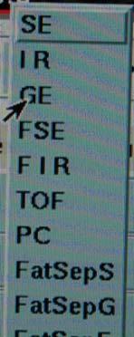
9 Creating MFH Test on Philips Check under the Contrast tab first From the ACR T1 protocol, you may simply be able to change the sequence from a SE to FFE If not, use the steps provided in the next slide Creating MFH Test on Philips Under Anatomy, select cervical, find T1 weighted FFE (Fast Field Echo equates to a GRE) 9


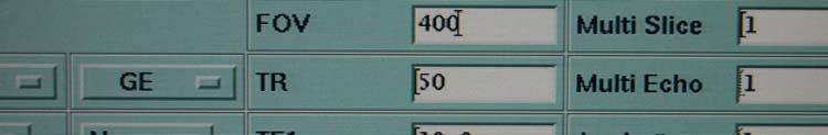
10 Philips MFH The trick for parameter manipulation is as clear as MUD for Philips BE AWARE! Philips boasts that changing the FOV also changes resolution, bandwidth and gradient waveform, so changing FOV also changes image quality You must determine FOV then manipulate pixel size to maintain a matrix of 256x256, which is not necessary on the exam card mode of scanning Philips MFH This is also very important during coil testing! 10


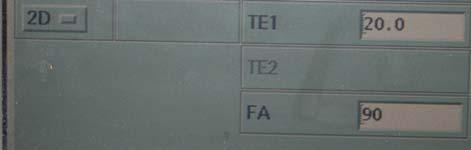
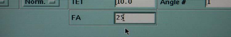
11 Easiest Way to Change Pixel Size on the Philips Scanner Right/Left arrow keys allow for greatest and fastest control Pretty spiffy, once you get used to it! Philips MFH Set parameters TR, TE, FA, FOV, matrix, then under Contrast Tab make sure you are 2D and adjust water/fat shift from 0.5 to 4 (this may appear on 2 different pages 11
 you MUST ensure this!")
12 Philips MFH Water fat shift (in pixels) is inversely proportional to Bandwidth (if other parameters remain the same) you MUST ensure this!!! I always force matrix to be 256 x 256 for ease Philips Bandwidth Calculator 12
 bandwidth is already displayed in khz under the optimization in")

13 Philips Bandwidth Calculator FYI on the Panorama software (0.23T) bandwidth is already displayed in khz under the optimization in the Acquisition tab Click on the Exam Explorer which is the pencil scribbling icon in the lower right corner and you can build ANYTHING! Siemens MFH 13
14 Siemens MFH Be sure to continually check your system tab throughout the testing of a Siemens unit to ensure that you are on the appropriate coil my suggestion is to turn AutoCoil Select OFF during testing and be sure to turn it back ON when you leave! Also, regularly verify that the coil is correct when you are browsing through the images by looking in the bottom left corner Siemens Receiver Bandwidth Determining the Receiver Bandwidth under the Resolution tab, record the Base Resolution (N f ). Under the Sequence tab, record the Bandwidth in Hertz/Pixel (Hz/Px) Receiver Bandwidth = Pixel Bandwidth x (1/2N f ) AGAIN! I force the Matrix to be 256x256, for ease of calculations 14

 Again getting the phantom to isocenter can be challenging use blankets Manipulating bandwidth is")
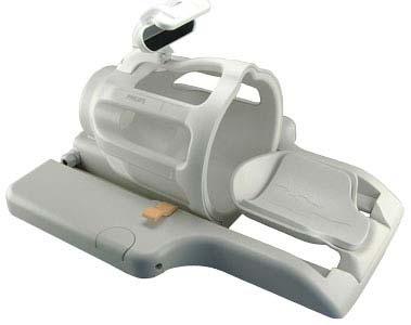
15 ONI Extremity Magnet Different diameter sleeves fill the bore I choose 160 mm to scan the small ACR phantom MFH For the Extremity Scanner I carry a small 10 cm, slightly larger than a baseball, GE sphere for doing magnetic field homogeneity on specialty magnets (you should get one too!) Again getting the phantom to isocenter can be challenging use blankets Manipulating bandwidth is easy on the ONI 15


16 MFH Values The 2004 ACR MRI Quality Control Manual states that typical values are around 2 ppm over a 30 to 40 cm diameter sphere My PQI project was done on >175 magnets of varying field strength with either a 24 cm, 28 cm or 30 cm sphere from 2009 now I found standardly that low field magnets should display < 5 ppm and high field magnets should be < 1 ppm. When MFH Fails 16

 Most often if a failure happens it is in the ACR sagittal")

17 Nuances per Vendor GE almost never fails, but when it does, it requires service 1 time I found GE in need of a gradient shim (which if you can wait on service, only takes 20 min for them to complete) Most often if a failure happens it is in the ACR sagittal localizer (which is the Z gradient) GE always makes this short to keep other parameters in tolerance Gradient Shim, Please! 17
18 From the ACR In an effort to maintain the Gold Seal of Accreditation, the ACR is implementing ICAMRL and JCAHO requirements for P&P manuals and safety The ACR states: The annual medical physicist/mr scientist performance evaluation must also include an assessment of the MRI safety program (signage, access control, screening procedures and cryogen safety) as well as an inspection of the physical and mechanical integrity of the system. From the ACR As the MP, you may be questioned on these topics: The ACR states: The MR equipment specifications and performance shall meet all state and federal requirements. The requirements include, but are not limited to, specifications of maximum static magnetic field strength, maximum rate of change of magnetic field strength (db/dt), maximum radiofrequency power deposition (specific absorption rate), and maximum auditory noise levels. 18
19 New from the ACR You are allowed to collect phantom images 6 months in advance of submission (although Phantom Data Scanning Form online entry only allows date < 4 months) Annual testing can be up to 14 months Image submission is now electronic The site may select electronic at the onset of the application process Use ClearCanvas Workstation Use TRIAD at You ve evaluated MFH, now what? You are the consultant physicist and you ve been hired to test a magnet for ACR submission, you ve never been to this facility and you have no idea how qualified the tech is First, you must assess the phantom. Are there bubbles? If yes, you should fill the phantom with distilled water. You will need: A 5/16 th nut driver. Sears sells them individually for $7 A syringe, with a blunt tip needle, no need to injure anyone! Distilled water Gloves & tissues or paper towels 19
20 Why Gloves? The phantom is filled with 10 millimole Nickel Chloride and 45 mmol Sodium Chloride (which simulates biological conductivity and comes with it s own MSDS sheet I URGE you to read this document! Nickel Chloride is toxic and potentially carcinogenic, particularly in dry form If a phantom (any MRI phantom) breaks please treat it as a hazardous materials spill Nickel Chloride is 1. Toxic and potentially carcinogenic 2. Is most dangerous in dry form 3. Used in the ACR phantom to simulate biological tissue 4. Is green in color 5. All of the above 20% 20% 20% 20% 20%


21 Nickel Chloride is 1. Toxic and potentially carcinogenic 2. Is most dangerous in dry form 3. Used in the ACR phantom to simulate biological tissue 4. Is green in color 5. All of the above Ref: Material Safety Data Sheet Liquid Nickel Chloride ScienceLab.com, (2012) Bubble in the phantom 21


22 Bubble in the phantom Bubble artifact Bubble in the phantom The ACR suggests that the technologist measure slightly offcenter for the weekly Geometric Accuracy QC if there is a bubble, but as the physicist, you should only submit the best images possible, so do your part and eliminate the bubble! 22


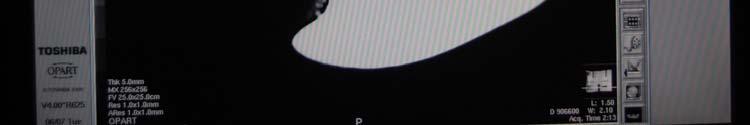
23 Location, Location, Location Setting up the phantom is based on many parameters The most important element is that you are always consistent! If you are not positioning the phantom yourself, you can t be sure from year to year that there is consistency i.e. Don t have the technologist position the phantom! Take your watch off and get in the game! Well, it is an Opart 23

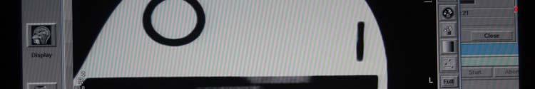
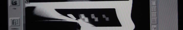
24 Something tells me. Susceptibility artifact, you bet! Metal in the magnet??? For sure! 24


25 Anyone see a problem here? Choosing the Coil The ACR has mandated that the coil that is used for imaging clinical brains MUST be the coil that is used to scan the ACR phantom. PERIOD. If a facility has a Quadrature (Birdcage) Coil and an 8 Channel High Resolution Brain Coil, you MUST ask which coil is being used clinically (almost never is it the Birdcage Bummer!) 25


26 Minimizing Motion Artifact If there are locks on the head coil, be sure to click locks into place or slide head coil until it locks Minimizing Motion Artifact If there are locks on the head coil, be sure to click locks into place 26


27 Minimizing Motion Artifact Minimizing Motion Artifact My trade secret is to use cushions or pads that are available in the MR suite to stabilize the phantom within the coil itself If the phantom cannot vibrate within the coil itself then we have eliminated 1 source of motion/ghosting artifact Actually worked with a service guy on a Hitachi Airis I who went into traffic trying to minimize road vibration! 27
28 Minimizing Motion Artifact Another trick is to flip PE with FE to diminish ghosting Motion is one of the few artifacts that is seen in the PE direction only. Why? FE fills in quickly (in the time of TE), PE fills in more slowly thereby allowing motion artifact to accumulate Flipping PE and FE will allow you to troubleshoot many artifacts Minimizing Motion Artifact Additional sources of motion can occur outside the phantom and the coil To further eliminate motion: It may be necessary to turn off the cold head (I have found this to be true on every model Toshiba makes and other vendors now due to the worldwide Helium shortage) Scan with the room lights OFF! Loose filaments in the bulbs can cause a pulsing in the RF signal which leads to artifacts 28
29 These artifacts are seen only in the phase encode direction: 1. Ghosting and Flow 2. Chemical Shift and Aliasing 3. Susceptibility and Truncation 4. Zipper and FID 5. Partial Volume and Arcing 20% 20% 20% 20% 20% These artifacts are seen only in the phase encode direction: 1. Ghosting and Flow 2. Chemical Shift and Aliasing 3. Susceptibility and Truncation 4. Zipper and FID 5. Partial Volume and Arcing Ref: A short overview of MRI artefacts, SA Journal of Radiology (2004) p
30 Side Bar on Lights Please be aware that Compact Fluorescent Light bulbs (CFLs) diminish your SNR by 20% without creating a visible artifact If you notice that SNR has decreased by 20% on every coil from your previous year s measurements, suspect the light bulbs first So to steal signal wherever you can on a low field magnet, change your bulbs and of course.lower your bandwidth! Which of the following is NOT a reason for motion in an MRI image? 1. Cryogen Boiling 2. Mechanical Vibrations 3. Large iron objects moving in the fringe field 4. Loose connections in the room lights 5. A leak in the Faraday cage 20% 20% 20% 20% 20%
31 Which of the following is NOT a reason for motion in an MRI image? 1. Cryogen Boiling 2. Mechanical Vibrations 3. Large iron objects moving in the fringe field 4. Loose connections in the room lights 5. A leak in the Faraday cage Ref: MRI artifacts and correction strategies, Future Medicine, (2010), 2(4), p Getting the Phantom to Isocenter of the Coil Tried and true method is the cheap stack of printer paper Do NOT use phantom cradles expensive and induce artifacts! Every facility has paper and the stack should be taped and labeled for future use (once the proper number of sheets is determined) Be sure to include in your kit: a plastic ruler, wooden shims, tape & a sharpie to label the paper I suggest measuring the front edge of the phantom to the top of the coil and recording that measurement for future use 31
")
32 Positioning the Phantom This particular skill set is an art, I assure you You will need a half a ream of printer paper for a birdcage coil, wood shims and a plastic level (also available at Sears) You will need a quarter of a ream of printer paper for an 8 Channel Brain coil, wood shims, plastic level and do NOT use alcohol prep pads (they can create a metal artifact seen on slice 11) Positioning the phantom in the High Res coil requires finesse, but is fairly easy once you adjust! Alcohol Prep Pad Artifact 32
33 Positioning the Phantom It is vital that you position the phantom in all 3 planes within the coil Most physicists only try to level the phantom in the x and y dimensions of the coil, but the yaw of the phantom can fail a low field magnet for LCD in a heartbeat, it will also cause you to fail slice thickness accuracy on a Siemens 1.5 T, which is notoriously on the high side 3 Plane Localizer The use of a 3 plane loc ACR does NOT require a 3 plane loc, only a sagittal loc Typically any skew will be in the Z dimension (along the table), which is indicated by a tilt in the coronal plane If you are on an open that does not have the ability to do a 3 plane loc in one scan, then you need to add an axial and coronal scout to the sagittal that is stored in the ACR protocol list. My suggestion is to drop the TR to 50 for these 2 scans so the total scan time is 13 sec per instead of the 56 sec scan for the ACR sag 33


34 3 Plane Localizer What the 3 plane loc also provides is a way to determine the phantom s location in the saddle If you are low axially, you are not at isocenter within the coil which causes a multitude of issues with uniformity on any magnet, but is particularly problematic for low field strengths that are struggling for signal 3 Plane Localizer Check your position in the saddle! 34


35 3 Plane Localizer Perfect positioning in the saddle, also check skew Before you do anything else!!! I CANNOT emphasize this enough!!! VERIFY that all parameters for the ACR protocols are correct! NEVER EVER trust if someone else saved the protocols! 35
36 Times will vary based on Vendor Study ACR Localizer ACR Axial T1 ACR Axial T2 Pulse Sequenc e Spin Echo Spin Echo Spin Echo Pulse Sequence Acquisition Parameters Field of Slice Slice Scan TR TE No. of Receiver View Width Gap NEX Matrix Time (ms) (ms) Slices BW (khz) (cm) (mm) (mm) (min:sec) N/A :56 Not Reported :16 Not 25 1 Reported / :56 Not 25 1 Reported Toshibas use 25/90 The entire ACR program was built on GE, so times are almost always correct for GE Helping the Technologist & Yourself Before you plan to scan the phantom according to the site s protocols, I suggest that you verify that their pixel resolution meets the ACR guidelines In plane pixel (phase) = FOV p /N p In plane pixel (frequency) = FOV f /N f Pixel area = (FOV p /N p ) x (FOV f /N f ) FOV p = Field of View phase N p = # of phase FOV f = Field of View frequency encode steps N f = # of freq encode steps 36
37 Pixel Resolution is: 1. Measured by the Field of View(p) divided by the pixel area 2. Measured by the Field of View(p) divided by the number of phase encode steps 3. Measured by the Number of phase encode steps divided by the Field of View(p) 4. Measured by the pixel area divided by the Field of View(p) 5. None of the above 20% 20% 20% 20% 20% Pixel Resolution is: 1. Measured by the Field of View(p) divided by the pixel area 2. Measured by the Field of View(p) divided by the number of phase encode steps 3. Measured by the Number of phase encode steps divided by the Field of View(p) 4. Measured by the pixel area divided by the Field of View(p) 5. None of the above Ref: MRI Accreditation Program Clinical Image Quality Guide, American College of Radiology, (2012) p 4 37
38 Pixel Resolution You may be asked to assist in doing the math on all clinical studies, refer to MRAP Clinical Guide under MRI Testing and QC Forms for limits For the clinical brain slice thick 5.0 mm slice gap 2.0 mm In plane pixel (read) 1.0 mm In plane pixel (phase) 1.2 mm Pixel area 1.2 mm 2 Large Phantom Data Scanning Form Study ACR Localizer ACR Axial T1 ACR Axial T2 Site's T1 Brain Site's T2 Brain Pulse Sequence Spin Echo Spin Echo Spin Echo Spin Echo Fast Spin Echo Field of Slice Slice TR TE No. of View Width Gap (ms) (ms) Slices (cm) (mm) (mm) NEX Matrix N/A / Freq: Phase: Freq: Phase: ACR T1 and T2 Filters Applied: Site T1 and T2 Filters Applied: Phantom Serial Number: 0 Pulse Sequence Acquisition Parameters T1 T2 Receiver BW (khz) Not Reported Not Reported Not Reported 38
39 Nuances per Vendor GE 8 Ch. Head Coil vs. Birdcage Any HR Brain coil requires SCIC or PURE be turned on to pass uniformity The button is next to the Graphic RX button on the control panel NEVER EVER use the ZIP512 filter on GE when collecting a phantom image on the site protocols, this filter was designed for even # of slices! Nuances per Vendor Siemens tricks to pass the phantom on a Viva or Concerto struggles with LCD, must run Site Protocols with NO FILTERS on and increase the NEX as high as possible to still stay under the 35 min time limit on the brain protocol. Siemens Symphony if it fails, it will fail slice thickness accuracy by being too large turn on Large FOV, Distortion Correction, Prescan Normalize. If playing with filters doesn t help, adjust the bandwidth to minimum. I have also had to play with gradient speed. Siemens Espree due to short bore, the unit is more susceptible to uniformity & homogeneity issues 39
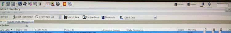
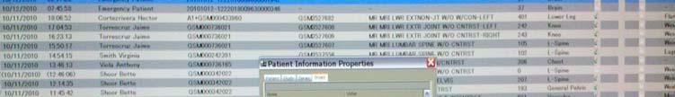
40 Nuances per Vendor Philips Intera or Achieva subtle differences in every magnet I have sat in front of. MFH on their 3T struggles in the Z direction When a Philips 3T struggles with uniformity you must play with CLEAR on and SENSE off and homogeneity strength to find what works Nuances per Vendor Philips I have not yet met a Panorama 1.0T Panorama software (0.23T) is completely different than the software that is used on the Intera or Achieva. One edition of their software allows for use in Exam Card Mode and Scan List, but not true for the Panorama or Ingenia Ingenia and Achieve R software and newer requires exiting the imaging platform to obtain CF and TG information for each scan Also, to properly tune a Philips coil, a new patient must be created for each and every coil. 40
41 Nuances per Vendor Toshiba Both high and low field strengths (yes, the Opart has a chiller) requires that the cold head be turned OFF prior to collecting phantom images for submission to eliminate ghosting/motion artifact most good techs know how to do this REMEMBER to turn the cold head on again prior to clinical scanning or your magnet might quench. Be sure to tell Service to address the motion caused by the vibration of the cold head Nuances per Vendor Fonar (all software) requires that Fonar service through the facility s phone line turn off the weighting factor for phantom image collection to pass uniformity REMEMBER call Fonar service again prior to clinical scanning and have weighting factor turned on The first time you do a Fonar, bite your tongue and schedule WITH FSE, it will save time. You will not be used to thinking in the planes that Fonar uses the ACR phantom and the software is tedious at best 41
42 Planning the Sagittal Loc From the 3 plane loc, position the sag loc so that it is perfectly centered Perfectly Positioned Sagittal 42
43 Verifying the Sagittal Loc If you have positioned everything perfectly, the sag loc should fit in a rectangle And the two ramps at the centered will form 1 straight line 2 wedges should be of equal prominence, if they aren t check that your slice thickness is the required 20 mm Oddities you may note In the sagittal localizer: There maybe a swoop in the upper right corner, this is due to geometric distortion. This is expected! Don t kill yourself trying to get rid of it. There maybe a hump in the middle as we saw above (if you are on a Siemens with Syngo software apply distortion correction & normalize filters to eliminate these expected artifacts) There maybe a zipper artifact slightly left of offcenter due to the width of the slice being so large (20 mm) seen typically on GEs 43
44 Planning the ACR T1 Planning the ACR T1 Ideal position of slice prescriptors is right through the apex of both wedge sets HOWEVER, this almost never works out You must choose which way to plan your scan, bear in mind the limitations of the system you are on As low field magnets struggle with LCD it is best to make sure that the center of slice 11 is perfectly aligned to the last row of LCD objects 44

45 Planning the ACR T1 Slice 11 Configuration for a low field magnet. We choose to align to LCD instead of slice 1 Slice 1 Planning the ACR T1 Ideal position of slice prescriptors is right through the apex of both wedge sets HOWEVER, this almost never works out You must choose which way to cheat As low field magnets struggle with LCD it is best to make sure that the center of slice 11 is perfectly aligned to the last row of LCD objects For high field magnets its (especially 1.5 T Siemens) aim for slice 1 to be perfect, as LCD isn t even a test on this field strength 45


 www.")
46 Checking Positioning on T1 Slice 1 Slice 11 Scanning the ACR T1 If the wedge is long on the same side this is a positioning error If the wedges are long on opposite sides, this is a GAP error and service must be called if slice position accuracy fails (GE s downfall because they shorten the distance in the table direction, making the sag geometric accuracy fail, so the gap is shortened AND this does cause slice position accuracy to fail) 46
47 Geometric Accuracy GE chronically fails this test by making the sag loc too short, normally on the order of 145 mm by calibrating the gradient along the table axis according to their specs If the unit is a low field GE (Profile or Ovation) speak to FSE prior to you visiting. Ask them to exceed their specs in the table direction (keep in mind this is NOT the Z gradient on a low field) in order to pass slice position accuracy Geometric Accuracy Why do we check accuracy on Sag Loc and both directions on Axial Scan? Why do we check accuracy on slice #1 AND #5? Or slice #1 and #3 on the small phantom? Typical failure is on the diagonal, whether it be short or long. This is the Z dimension (on a high field)! So why is the Z dimension so susceptible to failing this test? Bore gradient design is different for Z than for X and Y 47

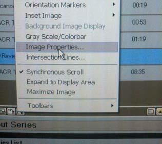
48 High Contrast Resolution I only mention this test here, as it causes more confusion than any other test Trick is to Window to min & Level independently! You MUST see 4 dots across 1 row in UL and 4 dots in 1 column in LR! Large Phantom 1.1 mm 1.0 mm 0.9 mm Small Phantom 0.9 mm 0.8 mm 0.7 mm Measuring Slice Thickness The only scanners I have seen this fail on is Siemens 1.5T, turn on Large FOV, Normalize and Distortion Correction Filters If you still struggle to pass this test, try minimizing the bandwidth and you should pass If you still fail, contact service, typically this indicates a problem with the RF amplifier Philips Enhanced DICOM shortens the slice thickness as visualized by KPACS! Measure again in KPACS prior to submission 48

 Raise level until the last pixel of signal is seen Record this as the Maximum signal (again, this number will be")
49 Ever seen this on a Siemens? Slice 7 on a Siemens scanner, doesn t appear uniform, there appears to be cross talk from slice 8 why is this visible? Remember, Siemens is always large on their slice thickness measurement?? Uniformity Measurement Window to minimum Raise level until first signal is seen in the large ROI that you have created Record this as the Minimum signal (I know this sounds dumb, but make sure this value is LESS than your mean) Raise level until the last pixel of signal is seen Record this as the Maximum signal (again, this number will be MORE than your mean!) My point is to ensure that you don t end up with a uniformity measurement of > than 100% 49
50 Uniformity Failure Location is everything! Make sure the phantom is at isocenter of the head coil! If the top of the birdcage is not secured to the bottom, you may see a failure (ALWAYS check the coil!) Poor uniformity goes hand in hand with decrease SNR If the phantom is properly positioned, call service Philips 3Ts require that you play with a number of factors to pass uniformity including SENSE, Clear and Homogeneity strength (remember reduced criteria for 3T!) On a 8 Ch. Brain coil, make sure to turn SCIC on! Percent Signal Ghosting First, if you fail this test numerically, every other test has already failed, which should be ridiculously obvious and shouldn t require a single measurement 50

51 Ghosting Artifacts Phantoms may rarely fail the percent signal ghosting numerically, but there will often be mention of a ghosting artifact Site T2s because they are chronically a Fast/Turbo Spin Echo will show increased ghosting, this is expected, but don t let it be excessive Shove pads into the head coil to minimize motion of the phantom, this should help with ghosting on the site T2 Improving LCD Make sure the prescription slices that you choose cheat to slice # 11 Make sure you are not skewed in the Z direction 51


52 Fusion Physics, LLC Establishing the Tech s QC The Medical Physicist s job is to establish the Tech QC s limits and perform any training that maybe required Training a tech on their system means you need to know where to find the data they need So let s go! 52


53 Tracking Center Frequency and Gain on GE This could not be easier on the GE scanner select the idle button then while the T1 is scanning, in the upper left hand corner AX is displayed, as is TG. AX is center frequency and TG is transmitter gain Or you can use the text page button below if the scan is already complete see next slides Tracking Center Frequency and Gain on GE 53


54 Tracking Center Frequency and Gain on GE Center Frequency Transmitter Gain Tracking Center Frequency and Gain on New GE Software 54


55 Tracking CF and TG on Siemens Tracking CF and TG on Siemens 55


56 Tracking CF and TG on Siemens New Software On Hitachi If Maintenance card is not at the bottom of your list, put it there! Hit Maint button in the center 56


57 Adding System Maintenance Card Choose SysMaintCard then hit done You should know how to do this to train your techs! Under Maintenance Card 57


58 On Hitachi Oasis Software On Hitachi Oasis Software 58


59 On Hitachi Oasis Software Tracking Center Frequency and Gain on Philips 59


60 Tracking Center Frequency and Gain on Philips Under previous scan choose #8, then click on double arrows until you see sp_proton_freq and SP_receiver_att Tracking Center Frequency and Gain on Philips click on double arrows until you see SP_receiver_att 60

61 Tracking Center Frequency and Gain on Philips Ingenia Ingenia: While the sequence is running, on the Main Menu (Upper Left) choose System, and DataMonitoring This will bring up a window showing the preparation phases for the currently running sequence. You must review this page prior to the next sequence beginning, or use a different method to bring up the data. Tracking Center Frequency and Gain on Philips Ingenia 61


62 Tracking Center Frequency and Gain on Philips Ingenia Tracking Center Frequency and Gain on Philips Ingenia 62


63 Tracking Center Frequency and Gain on Toshiba Tracking Center Frequency and Gain on FONAR Open info tab while in viewing mode: Then follow the next slide 63


64 Tracking Center Frequency and Gain on FONAR 64
4/14/2009. The Big Picture of Quality. MRI Quality Assurance and ACR MRI Accreditation Program. Basic Elements for Image Quality.
 The Big Picture of Quality MRI Quality Assurance and ACR MRI Accreditation Program Chen Lin, PhD Indiana University School of Medicine & Clarian Health Partners Diagnosis accuracy Image quality Knowledge
Phantom Test Guidance for Use of the Small MRI Phantom for the MRI Accreditation Program
 Phantom Test Guidance for Use of the Small MRI Phantom for the MRI Accreditation Program 1 Contents 0.0 INTRODUCTION 4 0.1 Overview and Purpose 4 0.2 The Phantom 4 0.3 The Required Images 5 0.4 The Image
MR Accreditation Programs - E. Jackson
 MRI Accreditation Programs: An Overview of Each and Specifics of One Edward F. Jackson, PhD Department of Imaging Physics 1 Diagnostic - MRI Safety and Accreditation Educational Objectives At the conclusion
Breast MR Imaging and Quality Control
 Breast MR Imaging and Quality Control Donna M. Reeve, MS, DABR, DABMP Department of Imaging Physics Educational Objectives 1. Provide an overview of breast MR imaging and MR-guided biopsy procedures. 2.
M R I Physics Course. Jerry Allison Ph.D. Chris Wright B.S. Tom Lavin M.S.M.P. Department of Radiology Medical College of Georgia
 M R I Physics Course Jerry Allison Ph.D. Chris Wright B.S. Tom Lavin M.S.M.P. Department of Radiology Medical College of Georgia M R I Physics Course chapter 12 Artifacts and Suppression Techniques Artifacts
RAD 465 (MRI) Lecture one (Pulse Sequences) Ruba Khushaim MSc
 Lecture one (Pulse Sequences) Ruba Khushaim MSc") RAD 465 (MRI) Lecture one (Pulse Sequences) Ruba Khushaim MSc Outline : Spine echo pulse sequence SE Fast spin echo pulse sequence FSE Inversion recovery pulse sequence IR Gradient pulse sequence GS Pulse
RAD 465 (MRI) Lecture one (Pulse Sequences) Ruba Khushaim MSc Outline : Spine echo pulse sequence SE Fast spin echo pulse sequence FSE Inversion recovery pulse sequence IR Gradient pulse sequence GS Pulse
Philips Site Yearly Performance Evaluation Philips Achieva - Gibbons 1.5T 1-Jun-08. Table of Contents
 Philips Site Yearly Performance Evaluation Philips Achieva Gibbons.T Jun8 Table of Contents Summary and Signature Page 2 Specific Comments 3 Site Information 4 Equipment Information 4 Table Position Accuracy
Procedure Manual for MRI of the Brain
 Baxter Protocol 161003 SYN RC W H E R E S C I E N C E M E E T S S E R V I C E Baxter Protocol 161003 A Phase 3 Randomized, Double-Blind, Placebo-Controlled Study of the Safety and Effectiveness of Immune
Abstract. Learning Objectives 8/1/2017
 SAM Practical Medical Physics TU-B-201-0 AAPM Annual Meeting 2017 1 Abstract This course will teach the participant to identify common artifacts found clinically in MR, DR, CT, PET, to determine the causes
Nuclear Associates and
 Nuclear Associates 76-907 and 76-908 AAPM MRI Phantoms Users Manual March 2005 Manual No. 38616 Rev. 3 2003, 2005 Fluke Corporation, All rights reserved. Printed in U.S.A. All product names are trademarks
Multiparametric MRI Prostate Imaging Protocol November 2015 Full Acquisition Protocol with Parameters GE 3T Magnet with Software Version DV25
 3Plane Loc SSFSE Multiparametric MRI Prostate Imaging Protocol November 2015 Full Acquisition Protocol with Parameters GE 3T Magnet with Software Version DV25 Save Series Scan After acquisition, scroll
Troubleshooting Guide. Prep, Scan Errors, and Artifacts
 Troubleshooting Guide Prep, Scan Errors, and Artifacts Preparing for the Study Participant Compliance with MRI Scans Participant Prep Having your participant prepped will allow you to run your study with
3/2/2016. Medical Display Performance and Evaluation. Objectives. Outline
 Medical Display Performance and Evaluation Mike Silosky, MS University of Colorado, School of Medicine Dept. of Radiology 1 Objectives Review display function, QA metrics, procedures, and guidance provided
True comfort and flexibility with the power of 3T.
 True comfort and flexibility with the power of 3T. With a large 71 cm aperture and the quietest exams in the industry, the Vantage Titan 3T is the most comfortable 3T MRI system for all of your patients.
Scope: All CT staff technologist
 APPROVED BY: Radiology Technical Director Page 1 of 6 Purpose: The QC program assesses relative changes in system performance as determined by the technologist, service engineer, qualified medical physicist,
Technologist Quality Control Procedures
 Technologist Quality Control Procedures The specific procedures for the Technologist Quality Control Program are those specified in the most current ACR MRI QC Manual. WEEKLY MRI EQUIPMENT QUALITY CONTROL
PATIENT POSITION IMAGING PARAMETERS
 3 PLANE LOC Patient Entry Feet First Imaging Mode 2D Patient Position Prone Pulse Sequence Gradient Echo Coil Configuration 7breast both MRI Imaging Options Seq, Fast Plane 3-PLANE Acceleration Factor
Display Quality Assurance: Considerations When Establishing a Display QA Program. Mike Silosky, M.S. 8/3/2017
 Display Quality Assurance: Considerations When Establishing a Display QA Program Mike Silosky, M.S. 8/3/2017 Objectives and Outline Why, Who, What, When, Where? Discuss the resources that may be needed
MSK Imaging Fundamentals
 MSK Imaging Fundamentals Goals Improve image quality Provide best possible product for our customers Patient Referring clinician Radiologist Reduce number of callback cases Goal reduction of 50% in 3 months
Image quality in non-gated versus gated reconstruction of tongue motion using Magnetic Resonance Imaging:
 This talk was presented 26 June 2008, at the 22nd International Congress and Exhibition of Computer Assisted Radiology and Surgery, in Barcelona at the Hotel Constanza from June 25 to 28, 2008. See http://kochanski.org/gpk/papers/2008/carstalk.html
Procedures for conducting User QA on the scanner
 Procedures for conducting User QA on the scanner Sample setup: The User QA phantom is clearly labeled and is stored on one of the shelves to the side of the magnet. Note proper orientation of the bottle,
Request for Proposals
 Request for Proposals Reference: ERDFIAI2012-4006A Caring First Ltd, is a limited liability company providing healthcare services. The company is currently commissioning a private new-build hospital complete
HITACHI S FAST SPIN ECHO TECHNOLOGY
 primefse TECHNOLOGY Yosuke Hitata RT Makoto Sasaki MD Kunio Esashika RT Hiroshi Gakumazawa RT HITACHI S FAST SPIN ECHO TECHNOLOGY Efficacies in Improving Image Quality & Usability Hitachi Medical Systems
Display Quality Assurance: Recommendations from AAPM TG270 for Tests, Tools, Patterns, and Performance Criteria
 Display Quality Assurance: Recommendations from AAPM TG270 for Tests, Tools, Patterns, and Performance Criteria Nicholas B. Bevins, Ph.D. TG270 Co-chair Display Check 2 1 TG270 Goals Provide an update
Display Quality Assurance: Recommendations from AAPM TG270 for Tests, Tools, Patterns, and Performance Criteria
 Display Quality Assurance: Recommendations from AAPM TG270 for Tests, Tools, Patterns, and Performance Criteria Nicholas B. Bevins, Ph.D. TG270 Co-chair Display Check 2 TG270 Goals Provide an update to
Light. Engineered for Performance- Esaote MRI, designed to make a difference.
 Engineered for Performance- Light Esaote MRI, designed to make a difference. Esaote MRI systems are designed to make a difference and the O-scan is fully in line with Esaote s design philosophy. For the
FFDM Quality Control in Canada - a Vendor Neutral Approach
 FFDM Quality Control in Canada - a Vendor Neutral Approach Rasika Rajapakshe, PhD, FCCPM BC Cancer Agency-Center for the Southern Interior Kelowna, BC, Canada 2011 Joint AAPM/COMP Meeting August 4, 2011
Standard Operating Procedure of nanoir2-s
 Standard Operating Procedure of nanoir2-s The Anasys nanoir2 system is the AFM-based nanoscale infrared (IR) spectrometer, which has a patented technique based on photothermal induced resonance (PTIR),
NMR. picospin. Maintenance Guide
 NMR picospin Maintenance Guide 269-302600 Revision A January 2013 2013 Thermo Fisher Scientific Inc. All rights reserved. For U.S. Technical Support, please contact: Thermo Fisher Scientific 5225 Verona
GS Bloch Equations Simulator 1. GS Introduction to Medical Physics IV Exercise 1: Discrete Subjects
 GS02-1193 Bloch Equations Simulator 1 GS02-1193 Introduction to Medical Physics IV Exercise 1: Discrete Subjects Once SpinWright is running, select the Subject tab. The GUI display toward the top of the
CMRRpack2. a collection of pulse sequences from the. University of Minnesota, Center for Magnetic Resonance Research (CMRR) Version: 2.
 Version: 2.") CMRRpack2 a collection of pulse sequences from the University of Minnesota, Center for Magnetic Resonance Research (CMRR) Version: 2.63_package This document generated: Mon Dec 16 2013 15:55:46 Contents
CMRRpack2 a collection of pulse sequences from the University of Minnesota, Center for Magnetic Resonance Research (CMRR) Version: 2.63_package This document generated: Mon Dec 16 2013 15:55:46 Contents
Equipment Quality Control for Digital Radiography February 22, Imaging Physics CancerCare Manitoba
 Equipment Quality Control for Digital Radiography February 22, 2018 Imaging Physics CancerCare Manitoba Purpose An equipment quality control (QC) program establishes baseline performance levels, tracks
Practicum 3, Fall 2010
 A. F. Miller 2010 T1 Measurement 1 Practicum 3, Fall 2010 Measuring the longitudinal relaxation time: T1. Strychnine, dissolved CDCl3 The T1 is the characteristic time of relaxation of Z magnetization
Multi echo Multi slice (MEMS) High Performance fmri at CFMRI... 1
 High Performance fmri at CFMRI... 1") Multi echo Multi slice (MEMS) High Performance fmri at CFMRI Table of Contents Multi echo Multi slice (MEMS) High Performance fmri at CFMRI... 1 Introduction... 2 MEMS Protocols... 4 Run MEMS protocol...
Multi echo Multi slice (MEMS) High Performance fmri at CFMRI Table of Contents Multi echo Multi slice (MEMS) High Performance fmri at CFMRI... 1 Introduction... 2 MEMS Protocols... 4 Run MEMS protocol...
INSTALATION PROCEDURE
 INSTALLATION PROCEDURE Overview The most difficult part of an installation is in knowing where to start and the most important part is starting in the proper start. There are a few very important items
Equipment Quality Control for Primary Displays June 5, Imaging Physics CancerCare Manitoba
 Equipment Quality Control for Primary Displays June 5, 2018 Imaging Physics CancerCare Manitoba Purpose An equipment quality control (QC) program establishes baseline performance levels, tracks system
EPI. Thanks to Samantha Holdsworth!
 EPI Faster Cartesian approach Single-shot, Interleaved, segmented, half-k-space Delays, etc -> Phase corrections Flyback EPI GRASE Thanks to Samantha Holdsworth! 1 EPI: Speed vs Distortion Fast Spin Echo
Guidelines for Assuring Softcopy Image Quality
 Guidelines for Assuring Softcopy Image Quality What s inside? Quality Control Guidelines Softcopy QA testing and frequencies Danny Deroo Product and R&D Manager QA Products ABSTRACT To ensure diagnostic
SNG-2150C User s Guide
 SNG-2150C User s Guide Avcom of Virginia SNG-2150C User s Guide 7730 Whitepine Road Revision 001 Richmond, VA 23237 USA GENERAL SAFETY If one or more components of your earth station are connected to 120
2012 Computed Tomography
 2012 Computed Tomography QUALITY CONTROL MANUAL Radiologist s Section Radiologic Technologist s Section Medical Physicist s Section 2012 Computed Tomography QUALITY CONTROL MANUAL Radiologist s Section
Standard. Substitute Test or Procedure. Required Test or. 1 Scan Increment Accuracy. Initially and Annually Initially and Annually
 Manufacturer s Recommendations for Alternate Dental CBCT QA Program VaTech: Model PAX i3d, i3d Green, i3d Smart Table 6 Medical Physicist s Computed Tomography QC Survey Required Test or Item Procedure
SC26 Magnetic Field Cancelling System
 SPICER CONSULTING SYSTEM SC26 SC26 Magnetic Field Cancelling System Makes the ambient magnetic field OK for electron beam tools in 300 mm wafer fabs Real time, wideband cancelling from DC to > 9 khz fields
Understanding CT image quality
 IAEA RER/9/135 COURSE ON OPTIMIZATION IN COMPUTED TOMOGRAPHY Sofia, Bulgaria, 2017 Understanding CT image quality Dean Pekarovič UMC Ljubljana, Institute of Radiology Quality and Safety office Role of
PINMRF. Checkout Quiz - Varian Inova-300 Version
 PINMRF Checkout Quiz - Varian Inova-300 Version Please carefully read every question and select the best answer(s). Some questions may have more than one correct answer. You must select all the correct
Peacefully quiet. Remarkably fast.
 Peacefully quiet. Remarkably fast. 2 Excellent image quality Streamlined workflow Outstanding patient comfort Toshiba Medical s Vantage Galan 3T offers a transformational experience for you and your patients
RSNA 2006 November 26 to December 1 Chicago. Guest author for ImPACT Dr. Koos Geleijns, Medical Physicist, Leiden University Medical Center.
 RSNA 2006 November 26 to December 1 Chicago Guest author for ImPACT Dr. Koos Geleijns, Medical Physicist, Leiden University Medical Center. Once again, more than 60,000 participants (including professional
Open up to Extremity MRI
 The Open E-MRI Open up to Extremity MRI After having changed the world of musculoskeletal MR imaging in 1992 with the introduction of Artoscan, the first dedicated MRI, Esaote reached a new target, merging
MTI-2100 FOTONIC SENSOR. High resolution, non-contact. measurement of vibration. and displacement
 A worldwide leader in precision measurement solutions MTI-2100 FOTONIC SENSOR High resolution, non-contact measurement of vibration and displacement MTI-2100 Fotonic TM Sensor Unmatched Resolution and
Cable System Installation Guide
 Overview Cable System Installation Guide 5/19/2008 Our recommended approach for the installation of your Circle Graphics Cable Systems on the panels in your market is to install the fixed hardware (namely
Practicum 3, Fall 2012
 A.- F. Miller 2012 T1&T2 Measurement 1 Practicum 3, Fall 2012 Measuring the longitudinal relaxation time: T1. Strychnine, dissolved CDCl3 The T1 is the characteristic time of relaxation of Z- magnetization,
Peacefully quiet. Remarkably fast.
 Peacefully quiet. Remarkably fast. Excellent image quality Streamlined workflow Outstanding patient comfort Canon Medical Systems Vantage Galan 3T offers a transformational experience for you and your
Achieve Accurate Critical Display Performance With Professional and Consumer Level Displays
 Achieve Accurate Critical Display Performance With Professional and Consumer Level Displays Display Accuracy to Industry Standards Reference quality monitors are able to very accurately reproduce video,
2017 Computed Tomography
 2017 Computed Tomography QUALITY CONTROL MANUAL Radiologist s Section Radiologic Technologist s Section Qualified Medical Physicist s Section 2017 Computed Tomography QUALITY CONTROL MANUAL Radiologist
IMSERC NMR MANUAL 05: Manual Operation of Agilent NMR Spectrometers (Chem350 Interface)
") IMSERC NMR MANUAL 05: Manual Operation of Agilent NMR Spectrometers (Chem350 Interface) Last updated: October 12, 2011 by Josh Kurutz THIS PAGE = QUICK START GUIDE 0) At the computer, make sure VNMRJ is
IMSERC NMR MANUAL 05: Manual Operation of Agilent NMR Spectrometers (Chem350 Interface) Last updated: October 12, 2011 by Josh Kurutz THIS PAGE = QUICK START GUIDE 0) At the computer, make sure VNMRJ is
Comparison of Robarts s 3T and 7T MRI Machines for obtaining fmri Sequences Medical Biophysics 3970: General Laboratory
 Comparison of Robarts s 3T and 7T MRI Machines for obtaining fmri Sequences Medical Biophysics 3970: General Laboratory Jacob Matthews 4/13/2012 Supervisor: Rhodri Cusack, PhD Assistance: Annika Linke,
Spatio-temporal inaccuracies of video-based ultrasound images of the tongue
 Spatio-temporal inaccuracies of video-based ultrasound images of the tongue Alan A. Wrench 1*, James M. Scobbie * 1 Articulate Instruments Ltd - Queen Margaret Campus, 36 Clerwood Terrace, Edinburgh EH12
ULTRA-TRAC APL INSTRUCTION MANUAL. Read and understand instructions before use. Patented. 851 Transport Drive Valparaiso, IN
 ULTRA-TRAC APL A C O U S T I C P I P E L O C A T O R INSTRUCTION MANUAL Read and understand instructions before use. Patented MADE IN USA 851 Transport Drive Valparaiso, IN 46383-8432 Phone: 888 4SENSIT
Monitor QA Management i model
 Monitor QA Management i model 1/10 Monitor QA Management i model Table of Contents 1. Preface ------------------------------------------------------------------------------------------------------- 3 2.
SC24 Magnetic Field Cancelling System
 SPICER CONSULTING SYSTEM SC24 SC24 Magnetic Field Cancelling System Makes the ambient magnetic field OK for the electron microscope Adapts to field changes within 100 µs Touch screen intelligent user interface
Coronis 5MP Mammo. The standard of care for digital mammography
 Coronis 5MP Mammo The standard of care for digital mammography The standard of care For thousands of women every day, details make all the difference. This understanding, along with many years of commitment
SC24 Magnetic Field Cancelling System
 SPICER CONSULTING SYSTEM SC24 SC24 Magnetic Field Cancelling System Makes the ambient magnetic field OK for the electron microscope Adapts to field changes within 100 µs Touch screen intelligent user interface
E X P E R I M E N T 1
 E X P E R I M E N T 1 Getting to Know Data Studio Produced by the Physics Staff at Collin College Copyright Collin College Physics Department. All Rights Reserved. University Physics, Exp 1: Getting to
2013, 2014 Hewlett-Packard Development Company, L.P.
 User Guide 2013, 2014 Hewlett-Packard Development Company, L.P. The only warranties for HP products and services are set forth in the express warranty statements accompanying such products and services.
LA1500R USER S GUIDE.
 LA1500R USER S GUIDE www.planar.com The information contained in this document is subject to change without notice. This document contains proprietary information that is protected by copyright. All rights
Laser Beam Analyser Laser Diagnos c System. If you can measure it, you can control it!
 Laser Beam Analyser Laser Diagnos c System If you can measure it, you can control it! Introduc on to Laser Beam Analysis In industrial -, medical - and laboratory applications using CO 2 and YAG lasers,
Operation Manual for. SCU1 Signal Conditioning Unit
 Operation Manual for SCU1 Signal Conditioning Unit Table of Contents 1. About this Manual 4 1.1. Symbols Glossary 4 2. Safe Use 4 3. Compatible Magnetometers 5 4. Introduction to the SCU1 5 4.1. Summary
Artifacts in Abdominopelvic MR A Pictorial Review
 Artifacts in Abdominopelvic MR A Pictorial Review Evan Allgood, MD Radiology Resident Harbor - University of California, Los Angeles Bijan Bijan, MD, MBA Professor of Radiology & Nuclear Medicine (WOS)
BitWise (V2.1 and later) includes features for determining AP240 settings and measuring the Single Ion Area.
 includes features for determining AP240 settings and measuring the Single Ion Area.") BitWise. Instructions for New Features in ToF-AMS DAQ V2.1 Prepared by Joel Kimmel University of Colorado at Boulder & Aerodyne Research Inc. Last Revised 15-Jun-07 BitWise (V2.1 and later) includes features
BitWise. Instructions for New Features in ToF-AMS DAQ V2.1 Prepared by Joel Kimmel University of Colorado at Boulder & Aerodyne Research Inc. Last Revised 15-Jun-07 BitWise (V2.1 and later) includes features
Mechanical aspects, FEA validation and geometry optimization
 RF Fingers for the new ESRF-EBS EBS storage ring The ESRF-EBS storage ring features new vacuum chamber profiles with reduced aperture. RF fingers are a key component to ensure good vacuum conditions and
Non-Uniformity Analysis for a Spatial Light Modulator
 Non-Uniformity Analysis for a Spatial Light Modulator February 25, 2002 1. Introduction and Purpose There is an inherent reflectivity non-uniformity in spatial light modulators, hereafter referred to as
Processing data with Mestrelab Mnova
 Processing data with Mestrelab Mnova This exercise has three parts: a 1D 1 H spectrum to baseline correct, integrate, peak-pick, and plot; a 2D spectrum to plot with a 1 H spectrum as a projection; and
Practice, Practice, Practice Using Prototek Digital Receivers
 Practice, Practice, Practice Using Prototek Digital Receivers You have purchased some of the finest locating tools in the business, but they don t do magic. Your skill at handling these tools and recognizing
APPLICATION NOTE RAPID ELECTROCHEMICAL ASSESSMENT OF PAINT
 Redefining Electrochemical Measurement 734 Louis Drive Warminster, PA 18974 Tel: (215) 682-9330 Fax: (215) 682-9331 www.gamry.com APPLICATION NOTE RAPID ELECTROCHEMICAL ASSESSMENT OF PAINT Overview The
Topic: Instructional David G. Thomas December 23, 2015
 Procedure to Setup a 3ɸ Linear Motor This is a guide to configure a 3ɸ linear motor using either analog or digital encoder feedback with an Elmo Gold Line drive. Topic: Instructional David G. Thomas December
Calibrating the timecode signal input
 Chapter 5 Calibrating the timecode signal input Computer hardware can introduce an offset between the timecode signal and the video signal, which causes the timecode and video to be offset when they are
Optimizing BNC PCB Footprint Designs for Digital Video Equipment
 Optimizing BNC PCB Footprint Designs for Digital Video Equipment By Tsun-kit Chin Applications Engineer, Member of Technical Staff National Semiconductor Corp. Introduction An increasing number of video
456 SOLID STATE ANALOGUE TAPE + A80 RECORDER MODELS
 456 SOLID STATE ANALOGUE TAPE + A80 RECORDER MODELS 456 STEREO HALF RACK 456 MONO The 456 range in essence is an All Analogue Solid State Tape Recorder the Output of which can be recorded by conventional
Setting Up the Warp System File: Warp Theater Set-up.doc 25 MAY 04
 Setting Up the Warp System File: Warp Theater Set-up.doc 25 MAY 04 Initial Assumptions: Theater geometry has been calculated and the screens have been marked with fiducial points that represent the limits
WAH WANG HOLDINGS (HONG KONG) CO., LTD.
 CO., LTD.") Wah Wang Data Sheet For 5mm Super Flux White LED High Reliable Type High Power 3 LED Chips Series RF-M05V53WUR4-B4-Q Address : Unit C, D & E, 12/F., Po Shau Centre, No. 115 How Ming Street Kwun Tong, Kowloon,
Wah Wang Data Sheet For 5mm Super Flux White LED High Reliable Type High Power 3 LED Chips Series RF-M05V53WUR4-B4-Q Address : Unit C, D & E, 12/F., Po Shau Centre, No. 115 How Ming Street Kwun Tong, Kowloon,
VeriLUM 5.2. Video Display Calibration And Conformance Tracking. IMAGE Smiths, Inc. P.O. Box 30928, Bethesda, MD USA
 VeriLUM 5.2 Video Display Calibration And Conformance Tracking IMAGE Smiths, Inc. P.O. Box 30928, Bethesda, MD 20824 USA Voice: 240-395-1600 Fax: 240-395-1601 Web: www.image-smiths.com Technical Support
Magnetic resonance imaging phase encoding:
 RadioGraphlcs Index terms: IMAGING TECHNOLOGY. Computer Applications MAGNETIC RESONANCE IMAGING #{149} Technical RADIATION PHYSICS #{149} Magnetic Resonance Imaging Cumulative Index terms: Magnetic resonance
Case 1 8/1/2017. Ring Artifact? James M. Kofler, Ph.D. Mayo Clinic Rochester. AAPM Annual Meeting TU-B Artifacts: CT 2
 James M. Kofler, Ph.D. Mayo Clinic Rochester AAPM Annual Meeting 2017 1 Case 1 Ring Artifact? 2 3 1 Star Pattern caused by metal earrings! 4 Same star artifact commonly caused by Dental Amalgam Metal Implants
ISOMET. Compensation look-up-table (LUT) and How to Generate. Isomet: Contents:
 and How to Generate. Isomet: Contents:") Compensation look-up-table (LUT) and How to Generate Contents: Description Background theory Basic LUT pg 2 Creating a LUT pg 3 Using the LUT pg 7 Comment pg 9 The compensation look-up-table (LUT) contains
Compensation look-up-table (LUT) and How to Generate Contents: Description Background theory Basic LUT pg 2 Creating a LUT pg 3 Using the LUT pg 7 Comment pg 9 The compensation look-up-table (LUT) contains
This talk covers currently available display technology.
 Introduction to Current Display Technologies for Medical Image Viewing Perspectives for the TG270 Update on Display Quality Control Alisa Walz-Flannigan, PhD (DABR) Mayo Clinic, Rochester, Minnesota AAPM
AFM1 Imaging Operation Procedure (Tapping Mode or Contact Mode)
") AFM1 Imaging Operation Procedure (Tapping Mode or Contact Mode) 1. Log into the Log Usage system on the SMIF web site 2. Open Nanoscope 6.14r1 software by double clicking on the Nanoscope 6.14r1 desktop
AFM1 Imaging Operation Procedure (Tapping Mode or Contact Mode) 1. Log into the Log Usage system on the SMIF web site 2. Open Nanoscope 6.14r1 software by double clicking on the Nanoscope 6.14r1 desktop
Power wasted without doing anything useful
 Vampire Power What is it? Electricity sucked by your appliances and electronics when not being used (even when turned off!) Power wasted without doing anything useful aka: Phantom Power Standby Power Parasite
PHGN 480 Laser Physics Lab 4: HeNe resonator mode properties 1. Observation of higher-order modes:
 PHGN 480 Laser Physics Lab 4: HeNe resonator mode properties Due Thursday, 2 Nov 2017 For this lab, you will explore the properties of the working HeNe laser. 1. Observation of higher-order modes: Realign
MQSA Quality Control Manual
 MQSA Quality Control Manual For The MX50T, MX50N, & CX50N 5 Mega-Pixel LCD Monitors (Document Number: OMI-1035) WIDE Corporation Document No. OMI-1035 Rev. No. 1.2 Page 1 CONTENTS Revision History 4 Documents
MIE 402: WORKSHOP ON DATA ACQUISITION AND SIGNAL PROCESSING Spring 2003
 MIE 402: WORKSHOP ON DATA ACQUISITION AND SIGNAL PROCESSING Spring 2003 OBJECTIVE To become familiar with state-of-the-art digital data acquisition hardware and software. To explore common data acquisition
Check our knowledge base at
 USER MANUAL Check our knowledge base at www.paralinx.net/support Copyright 2015 Paralinx LLC All Rights Reserved TABLE OF CONTENTS 1 Important Notice 10 LCD Screen 2 Safety Instructions 11 Indicators 3
TT AFM LongBeach Procedures and Protocols V2.1
 TT AFM LongBeach Procedures and Protocols V2.1 1. Startup Procedure 1. Turn on PC: Allow to boot to Windows. Turn on monitor. Password is afm 2. Turn on second PC that controls the video camera. 3. Turn
Getting Started with the LabVIEW Sound and Vibration Toolkit
 1 Getting Started with the LabVIEW Sound and Vibration Toolkit This tutorial is designed to introduce you to some of the sound and vibration analysis capabilities in the industry-leading software tool
An Introduction to the Spectral Dynamics Rotating Machinery Analysis (RMA) package For PUMA and COUGAR
 package For PUMA and COUGAR") An Introduction to the Spectral Dynamics Rotating Machinery Analysis (RMA) package For PUMA and COUGAR Introduction: The RMA package is a PC-based system which operates with PUMA and COUGAR hardware to
An Introduction to the Spectral Dynamics Rotating Machinery Analysis (RMA) package For PUMA and COUGAR Introduction: The RMA package is a PC-based system which operates with PUMA and COUGAR hardware to
Technical Procedure for Scanning Electron Microscope/ Energy Dispersive X-Ray System (SEM/EDX) for non-gsr Casework
 for non-gsr Casework") Technical Procedure for Scanning Electron Microscope/ Energy Dispersive X-Ray System (SEM/EDX) for non-gsr Casework 1.0 Purpose This technical procedure shall be followed for the operation of the Scanning
Technical Procedure for Scanning Electron Microscope/ Energy Dispersive X-Ray System (SEM/EDX) for non-gsr Casework 1.0 Purpose This technical procedure shall be followed for the operation of the Scanning
SATRI AMPLIFIER AMP-51R. Owner s Manual
 SATRI AMPLIFIER AMP-51R Owner s Manual contents SAFETY INSTRUCTIONS 4 INTRODUCTION 6 OVERVIEW (FRONT PANEL) 8 OVERVIEW (REAR PANEL) 9 OVERVIEW (REMOTE CONTROL) 1 1 OPERATION 12 TROUBLESHOOTING 13 SPECIFICATION
HOT LINKS Trade Show Schedule ISO Certification Contact
 July 2012 HOT LINKS Trade Show Schedule ISO Certification Contact Single-Field Scanning - Reduced Sensitivity To Contamination, Higher Quality PRODUCT SPOTLIGHT The type of scanning in harsh operating
RF Explorer RackPRO. User Manual. Introduction. Greetings fellow traveler on the RF spectrum.
 RF Explorer RackPRO User Manual Introduction Greetings fellow traveler on the RF spectrum. The RF Explorer RackPRO (referred to in this document in shorthand as RackPRO ) has been designed to be intuitive
Features. = +25 C, IF = 1 GHz, LO = +13 dbm*
 v.5 HMC56LM3 SMT MIXER, 24-4 GHz Typical Applications Features The HMC56LM3 is ideal for: Test Equipment & Sensors Point-to-Point Radios Point-to-Multi-Point Radios Military & Space Functional Diagram
Promises and Perils of Proton Therapy Beam Delivery (Implications) or Towards Cost Effective Particle Therapy
 or Towards Cost Effective Particle Therapy") Promises and Perils of Proton Therapy Beam Delivery (Implications) or Towards Cost Effective Particle Therapy Jay Flanz MGH/FBTC Harvard Medical School What is a Beam Delivery? Start with an accelerator
Promises and Perils of Proton Therapy Beam Delivery (Implications) or Towards Cost Effective Particle Therapy Jay Flanz MGH/FBTC Harvard Medical School What is a Beam Delivery? Start with an accelerator
Procedure for Acquiring 2D Inverse Detection Spectra HMQC, HMBC and HSQC
 Procedure for Acquiring 2D Inverse Detection Spectra HMQC, HMBC and HSQC This protocol is for qualified users operating Bruker Avance 400 in IBC only. Dr. Jao STOP accepts no responsibility for actions