M R I Physics Course. Jerry Allison Ph.D. Chris Wright B.S. Tom Lavin M.S.M.P. Department of Radiology Medical College of Georgia
|
|
|
- Shona Wilcox
- 5 years ago
- Views:
Transcription
1 M R I Physics Course Jerry Allison Ph.D. Chris Wright B.S. Tom Lavin M.S.M.P. Department of Radiology Medical College of Georgia
2 M R I Physics Course chapter 12 Artifacts and Suppression Techniques Artifacts / Undesirable Contrast Chemical Shift artifact Truncation (Gibbs) Artifact Errors in data Aliasing (wrap around) Zippers / Stars (Zero line artifact) Flow artifact Metallic artifact (magnetic field perturbations)
3 M R I Physics Course chapter 12 Artifacts and Suppression Techniques Motion Magnetic Susceptibility artifact Surface Coil artifact N/2 Ghosts in EPI
4 Chemical shift artifacts -At 1.5T the Larmor frequency of fat is approximately 220 Hz lower than water. MRI images can be considered to be images of free water with a superimposed spatially misregistered fat image. -Chemical shift artifacts produce high intensity and low intensity bands near fat/water interfaces, primarily in the frequency encode direction. -Dark boundaries between regions are sometimes called contour artifacts. 4


5 Kidney example: from the website ( by Ray Ballinger) 5

6 Copyright Radiological Society of North America, 1999 Williams, R. L. et al. Radiology 1999;212:

7 Chemical shift at 7T: oil and water
8 Truncation (Gibbs) artifact -Truncation artifact or Gibbs phenomena appear as a periodic ringing at high contrast interfaces. -Truncation artifact is caused by underestimation or overestimation of the signal at high contrast boundaries. 8
9 Truncation (Gibbs) artifact -The step function resulting from a high contrast interface cannot be accurately depicted by the finite number of sine and cosine waves prescribed by a typical MR image acquisition matrix. -Truncation artifacts can be diminished by a decrease in pixel size or raw data filtering. It is important to remember that raw data filtering affects all image data not just the artifactual portions. -Pixel size can be decreased by increasing the imaging matrix or decreasing the field of view. 9
10 Partial Volume Artifacts -Caused by an imaging voxel containing two different tissues and therefore possessing a signal average of both tissues. 10

11 11
12 Errors in data -Errors in data can cause striped images, washed out images and zipper artifacts. -Failure of the array processor can produce a variety of stripes and patterns (i.e. corduroy artifacts) on reconstructed images. 12
13 -Leaking RF shield: The exam room is RF shielded to attenuate RF energy from radio, television, etc. Failure of the shield can produce zipper artifacts. To demonstrate a leaking RF shield, scan with the door open. A simple test of the RF shield is to see if a transistor radio receives signal in the exam room with the door closed. 13
14 RF receiver gain -If the RF receiver gain is set such that the voltage level of the amplified signal exceeds the voltage range of the ADC, washed out images result. -The RF receiver gain settings are generally adjusted by auto prescan to avoid this artifact. 14
15 Aliasing (wrap-around) -Aliasing or wrap-around artifacts can occur when the anatomy exceeds the field of view. Aliasing can occur in the frequency encode direction or the phase encode direction. 15
16 16
17 Aliasing (wrap-around) -Solution 1: Sampling faster may reduce or eliminate aliasing but results in an increased receiver bandwidth with decreased SNR. 17
18 Aliasing (wrap-around) Solution 2:-Use of a larger FOV than actually desired and display of the central non-aliased portion of the image. This is the essence of No Phase Wrap, No Frequency Wrap and Oversampling. Aliasing in the frequency encode direction is generally prevented on modern MRI systems by oversampling. 18
19 19
20 Aliasing (wrap-around) -Siemens: Oversampling in the frequency encode direction doubles the number of points sampled. -GE: Oversampling in the frequency encode direction is always utilized. -Oversampling in the frequency encode direction does not change image acquisition time (or number of slices or echo time). 20
21 Aliasing (wrap-around) -Aliasing also occurs in the phase encode direction. This can be cured by use of No Phase Wrap:GE or Oversampling:Siemens. -Siemens: Oversampling in the phase encode direction increases the number of phase encodes by a user selectable percentage. -GE: No Phase Wrap doubles the number of phase encode samples (and halves the number of excitations). 21
22 22
23 Aliasing (wrap-around) -Removal of phase encode aliasing can require additional scan time. -In gradient recalled echo imaging, aliasing may produce a pronounced zebra stripe artifact. This artifact can be eliminated by oversampling ( No Phase Wrap ) or increasing the FOV. 23
24 Aliasing (wrap-around) -Aliasing can occur in the slice encoding direction in a 3D data set. GE routinely discards the four outermost slices in a 3D data set (acquire 128 slices; displays 124 slices: acquire 64 slices; display 60 slices: acquire 32 slices; display 28 slices). Aliasing or wrap-around in the slice encoding direction is often still visible in the outermost slices. -The phase encode axis is usually chosen as the narrower aspect of anatomy in order to minimize phase encoding aliasing. 24
25 Aliasing (wrap-around) -Solution 3: SAT uration bands can be applied outside the FOV to reduce aliasing artifacts. 25
26 Zippers/Stars (Zero line artifact) -Bands having a dashed appearance through the center of image. -Stars consist of a bright dot in the center of the image with dashed line tails along the frequency and phase encode directions. -The signal for each point in an MRI image is actually a sinc function ([sin x] / x) in both the frequency encode and the phase encode direction. 26
27 Zippers/Stars (Zero line artifact) -The sinc function signal actually contributes to several pixels in an image but ordinarily the signal side lobes is 27 small and is not recognized in an image.
28 Zippers/Stars (Zero line artifact) -A large noise signal can cause zipper or star artifacts. If the noise signal has large amplitude the signal from side lobes is large enough to show up as a dashed pattern in the reconstructed image. 28
29 Flow artifacts -Flow artifacts occur due to in-flow/out-flow time of flight phenomena and due to phase accumulation in a gradient magnetic field. 29
30 Flow artifacts -Flow compensation (gradient motion rephasing) can recover some phase dispersion attributable to flow. 1st order gradient moment nulling: compensation for constant velocity 30
31 Flow artifacts -Depends on -Flow velocity -Flow direction -Slice thickness -TR / TE -Direction of artifacts can be reversed by swapping the phase and frequency encode directions. 31
32 Metallic artifacts (magnetic field perturbations) -Metals can cause distortions in the static magnetic field. -Ferromagnetic metals can dramatically distort the static field due to the alignment of many magnetic domains. -Non-ferromagnetic metals can distort the static magnetic field due to smaller magnetic susceptibility effects. -Metal artifacts are generally worse with gradient recalled echo sequences than with spin echo 32 sequences.
33 Metallic artifacts -During imaging, eddy currents may be induced in some metal objects resulting in induced magnetism. -The effect of metallic objects is signal loss and image distortion: -Ferromagnetic metal -Cosmetics (Fe, Co) -Dental amalgams -Implants -Non-ferromagnetic metal -Shrapnel 33

34 Artifacts and Suppression Techniques Signal voids near metal implants (e.g., fillings, as in this gradient-echo picture) are due to magnetic susceptibility differences. MRI artifact website, Vancouver, BC Copyright 1996, Wayne Patola and Bruce Coulter 34
35 Motion -Patient motion produces ghost images; primarily in the phase encode direction. -In the frequency encode direction, motion produces little displacement in the 4-8 msec interval when data are collected. 35
36 Motion Artifacts and Suppression Techniques -In the phase encode direction, motion can produce large displacements (and associated large phase errors) since it can be as much as a few seconds between collection of adjacent lines of k-space. -Solutions for motion artifacts include: -Restraints -Physiological triggering to capture anatomy in the same aspect of the respiratory or cardiac cycle for each line of k-space. -Cardiac triggering is used frequently. -Peripheral gating is available. -Respiratory triggering is available but impractical. 36
37 Solutions for motion artifacts include: -Respiratory-Ordered Phase Encoding (ROPE) also known as respiratory compensation or retrospective cardiac gating. Each acquisition is assigned to k-space based upon the respiratory phase or cardiac phase when it was acquired. Retrospective cardiac gating is similar to a first pass MUGA scan in Nuclear Medicine. -Fat suppression to eliminate bright ghosting from moving fat. -ChemSAT -STIR -SAT bands 37
38 Magnetic susceptibility artifacts -The magnetic susceptibility of material present in an MRI image varies. Various soft tissues have various magnetic susceptibilities. Air has a very low magnetic susceptibility. Iron deposits from hemorrhage, liver iron overload, etc. have very high magnetic susceptibility. 38
39 Magnetic susceptibility artifacts -Perturbations in the static magnetic field due to magnetic susceptibility can cause geometric distortion and changes in signal intensity. Geometric distortions occur primarily in the frequency encode direction. Signal intensity can be increased or decreased by magnetic susceptibility. The artifacts caused by magnetic susceptibility can sometimes be observed in slices adjacent to the inhomogeneity. These artifacts may be more prominent on gradient recalled echo images or long TE spin echo images. Magnetic susceptibility may be useful contrast for imaging of calcification and hemorrhage. 39

40 Phantom Susceptibility in a T2* Weighted Sequence
")
41 Susceptibility Artifact in Orthogonal T2* (EPI) images
42 Surface coil artifact -The sensitivity of surface coils falls off dramatically with distance from the coil. Tissues close to the surface coil will have higher intensity than tissues farther from the coil. This artifact is very apparent in T 1 weighted imaging of the spine where subcutaneous fat produces very intense signal due to it s short T 1 value and proximity to the coil. -GE Signa has an option Image Intensity Correction that is designed to reduce surface coil artifacts (not used). 42
 brain")
43 Surface Coil Artifact -Notice how the SNR varies across the FOV for an 8 channel (parallel) brain coil. 43
44 N / 2 Ghosts in EPI -EPI is very sensitive to ghosting artifacts. Because the MRI signal is sampled under alternating gradients, it is necessary to reverse (invert) every other line. Any imperfection in the entire MRI imaging chain can modulate the MRI signal at half the Nyquist frequency. The result can be an N / 2 ghost in the phase encode direction. - N / 2 ghosts can be minimized by: -calibration scans (with no phase encodes) -image filtering 44

45 GHOSTS! 45
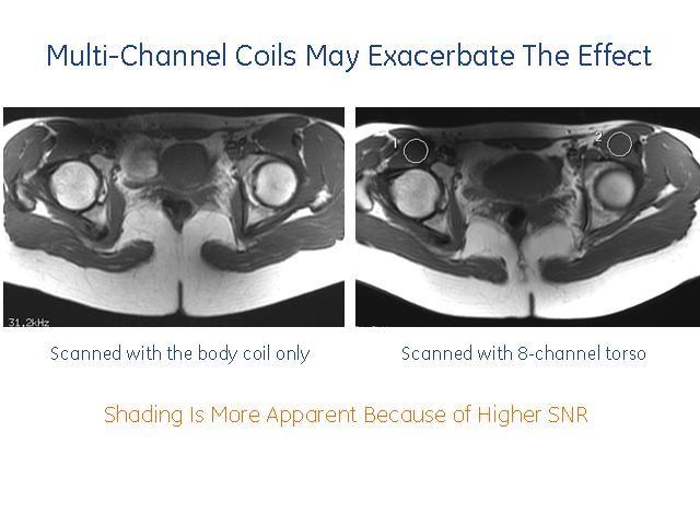
46 Challenge: Dielectric Resonance Larmor frequency increases for stronger magnets RF wavelength approaches body dimensions and FOV dimensions λ air = 4.7m at 1.5T λ air = 2.35m at 3T λ tissue = 0.3m at 3T!!!!!!!! (high dielectric constant) Can produce dielectric resonances which may reduce RF penetration Standing waves Image shading Worse in body imaging than head Worse in large patients (obese) Dielectric resonance effects occur at all field strengths but become apparent at 3T 46

47 Challenge: Dielectric Resonance UGA (Torso Array) 47
 T2 T2 STIR 48")
48 Challenge: Dielectric Resonance MCG (Torso Array) T2 T2 STIR 48
49 2006 GE Healthcare

50 2006 GE Healthcare

51 2006 GE Healthcare

52 2006 GE Healthcare
Abstract. Learning Objectives 8/1/2017
 SAM Practical Medical Physics TU-B-201-0 AAPM Annual Meeting 2017 1 Abstract This course will teach the participant to identify common artifacts found clinically in MR, DR, CT, PET, to determine the causes
RAD 465 (MRI) Lecture one (Pulse Sequences) Ruba Khushaim MSc
 Lecture one (Pulse Sequences) Ruba Khushaim MSc") RAD 465 (MRI) Lecture one (Pulse Sequences) Ruba Khushaim MSc Outline : Spine echo pulse sequence SE Fast spin echo pulse sequence FSE Inversion recovery pulse sequence IR Gradient pulse sequence GS Pulse
RAD 465 (MRI) Lecture one (Pulse Sequences) Ruba Khushaim MSc Outline : Spine echo pulse sequence SE Fast spin echo pulse sequence FSE Inversion recovery pulse sequence IR Gradient pulse sequence GS Pulse
4/14/2009. The Big Picture of Quality. MRI Quality Assurance and ACR MRI Accreditation Program. Basic Elements for Image Quality.
 The Big Picture of Quality MRI Quality Assurance and ACR MRI Accreditation Program Chen Lin, PhD Indiana University School of Medicine & Clarian Health Partners Diagnosis accuracy Image quality Knowledge
Artifacts in Abdominopelvic MR A Pictorial Review
 Artifacts in Abdominopelvic MR A Pictorial Review Evan Allgood, MD Radiology Resident Harbor - University of California, Los Angeles Bijan Bijan, MD, MBA Professor of Radiology & Nuclear Medicine (WOS)
EPI. Thanks to Samantha Holdsworth!
 EPI Faster Cartesian approach Single-shot, Interleaved, segmented, half-k-space Delays, etc -> Phase corrections Flyback EPI GRASE Thanks to Samantha Holdsworth! 1 EPI: Speed vs Distortion Fast Spin Echo
MSK Imaging Fundamentals
 MSK Imaging Fundamentals Goals Improve image quality Provide best possible product for our customers Patient Referring clinician Radiologist Reduce number of callback cases Goal reduction of 50% in 3 months
Phantom Test Guidance for Use of the Small MRI Phantom for the MRI Accreditation Program
 Phantom Test Guidance for Use of the Small MRI Phantom for the MRI Accreditation Program 1 Contents 0.0 INTRODUCTION 4 0.1 Overview and Purpose 4 0.2 The Phantom 4 0.3 The Required Images 5 0.4 The Image
Breast MR Imaging and Quality Control
 Breast MR Imaging and Quality Control Donna M. Reeve, MS, DABR, DABMP Department of Imaging Physics Educational Objectives 1. Provide an overview of breast MR imaging and MR-guided biopsy procedures. 2.
Troubleshooting Guide. Prep, Scan Errors, and Artifacts
 Troubleshooting Guide Prep, Scan Errors, and Artifacts Preparing for the Study Participant Compliance with MRI Scans Participant Prep Having your participant prepped will allow you to run your study with
Magnetic resonance imaging phase encoding:
 RadioGraphlcs Index terms: IMAGING TECHNOLOGY. Computer Applications MAGNETIC RESONANCE IMAGING #{149} Technical RADIATION PHYSICS #{149} Magnetic Resonance Imaging Cumulative Index terms: Magnetic resonance
Nuclear Associates and
 Nuclear Associates 76-907 and 76-908 AAPM MRI Phantoms Users Manual March 2005 Manual No. 38616 Rev. 3 2003, 2005 Fluke Corporation, All rights reserved. Printed in U.S.A. All product names are trademarks
Comparison of Robarts s 3T and 7T MRI Machines for obtaining fmri Sequences Medical Biophysics 3970: General Laboratory
 Comparison of Robarts s 3T and 7T MRI Machines for obtaining fmri Sequences Medical Biophysics 3970: General Laboratory Jacob Matthews 4/13/2012 Supervisor: Rhodri Cusack, PhD Assistance: Annika Linke,
Chapter 7. Scanner Controls
 Chapter 7 Scanner Controls Gain Compensation Echoes created by similar acoustic mismatches at interfaces deeper in the body return to the transducer with weaker amplitude than those closer because of the
Release Notes. Multi-Band EPI C2P. Release February 2013
 Release Notes Multi-Band EPI C2P Release 008 13 February 2013 Installation 1. Restart the system (reboot host and MRIR) 2. Extract the.zip file to a temporary directory 3. Run the installer.bat file 4.
Bioengineering 508: Physical Aspects of Medical Imaging Nature of Medical Imaging. Nature of Medical Imaging
 Bioengineering 508: Physical Aspects of Medical Imaging http://courses.washington.edu/bioen508/ Bioengineering 508: Physical Aspects of Medical Imaging Organizer: Paul Kinahan, PhD Adam Alessio, PhD Ruth
Image quality in non-gated versus gated reconstruction of tongue motion using Magnetic Resonance Imaging:
 This talk was presented 26 June 2008, at the 22nd International Congress and Exhibition of Computer Assisted Radiology and Surgery, in Barcelona at the Hotel Constanza from June 25 to 28, 2008. See http://kochanski.org/gpk/papers/2008/carstalk.html
Guide to artifacts in MRI: classification, explanation, countermeasures.
 Guide to artifacts in MRI: classification, explanation, countermeasures. Poster No.: C-1089 Congress: ECR 2017 Type: Educational Exhibit Authors: A. Cassarà 1, G. Fini 1, T. Bongiovanni 1, F. Cartabbia
Supplementary Course Notes: Continuous vs. Discrete (Analog vs. Digital) Representation of Information
 Representation of Information") Supplementary Course Notes: Continuous vs. Discrete (Analog vs. Digital) Representation of Information Introduction to Engineering in Medicine and Biology ECEN 1001 Richard Mihran In the first supplementary
Supplementary Course Notes: Continuous vs. Discrete (Analog vs. Digital) Representation of Information Introduction to Engineering in Medicine and Biology ECEN 1001 Richard Mihran In the first supplementary
PATIENT POSITION IMAGING PARAMETERS
 3 PLANE LOC Patient Entry Feet First Imaging Mode 2D Patient Position Prone Pulse Sequence Gradient Echo Coil Configuration 7breast both MRI Imaging Options Seq, Fast Plane 3-PLANE Acceleration Factor
HITACHI S FAST SPIN ECHO TECHNOLOGY
 primefse TECHNOLOGY Yosuke Hitata RT Makoto Sasaki MD Kunio Esashika RT Hiroshi Gakumazawa RT HITACHI S FAST SPIN ECHO TECHNOLOGY Efficacies in Improving Image Quality & Usability Hitachi Medical Systems
MR Accreditation Programs - E. Jackson
 MRI Accreditation Programs: An Overview of Each and Specifics of One Edward F. Jackson, PhD Department of Imaging Physics 1 Diagnostic - MRI Safety and Accreditation Educational Objectives At the conclusion
True comfort and flexibility with the power of 3T.
 True comfort and flexibility with the power of 3T. With a large 71 cm aperture and the quietest exams in the industry, the Vantage Titan 3T is the most comfortable 3T MRI system for all of your patients.
Experiences in ACR MRI Accreditation Vendor Nuances That Every Clinical MRI Physicist Should Know
 Experiences in ACR MRI Accreditation Vendor Nuances That Every Clinical MRI Physicist Should Know By Kathryn (Kat) W. Huff, M.S., DABR Prepared for The 2013 AAPM Spring Clinical Meeting Validating Me I
Calibrate, Characterize and Emulate Systems Using RFXpress in AWG Series
 Calibrate, Characterize and Emulate Systems Using RFXpress in AWG Series Introduction System designers and device manufacturers so long have been using one set of instruments for creating digitally modulated
NanoGiant Oscilloscope/Function-Generator Program. Getting Started
 Getting Started Page 1 of 17 NanoGiant Oscilloscope/Function-Generator Program Getting Started This NanoGiant Oscilloscope program gives you a small impression of the capabilities of the NanoGiant multi-purpose
SPATIAL LIGHT MODULATORS
 SPATIAL LIGHT MODULATORS Reflective XY Series Phase and Amplitude 512x512 A spatial light modulator (SLM) is an electrically programmable device that modulates light according to a fixed spatial (pixel)
EMI/EMC diagnostic and debugging
 EMI/EMC diagnostic and debugging 1 Introduction to EMI The impact of Electromagnetism Even on a simple PCB circuit, Magnetic & Electric Field are generated as long as current passes through the conducting
2
 1 2 3 4 5 6 7 1. Bauhs, J. A., Vrieze, T. J., Primak, A. N., Bruesewitz, M. R., & McCollough, C. H. (2008). CT Dosimetry: Comparison of Measurement Techniques and Devices1. Radiographics, 28(1), 245-253.
Peacefully quiet. Remarkably fast.
 Peacefully quiet. Remarkably fast. Excellent image quality Streamlined workflow Outstanding patient comfort Canon Medical Systems Vantage Galan 3T offers a transformational experience for you and your
ni.com Digital Signal Processing for Every Application
 Digital Signal Processing for Every Application Digital Signal Processing is Everywhere High-Volume Image Processing Production Test Structural Sound Health and Vibration Monitoring RF WiMAX, and Microwave
Procedure Manual for MRI of the Brain
 Baxter Protocol 161003 SYN RC W H E R E S C I E N C E M E E T S S E R V I C E Baxter Protocol 161003 A Phase 3 Randomized, Double-Blind, Placebo-Controlled Study of the Safety and Effectiveness of Immune
Introduction to the oscilloscope and digital data acquisition
 Introduction to the oscilloscope and digital data acquisition Eric D. Black California Institute of Technology v1.1 There are a certain number of essential tools that are so widely used that every aspiring
BitWise (V2.1 and later) includes features for determining AP240 settings and measuring the Single Ion Area.
 includes features for determining AP240 settings and measuring the Single Ion Area.") BitWise. Instructions for New Features in ToF-AMS DAQ V2.1 Prepared by Joel Kimmel University of Colorado at Boulder & Aerodyne Research Inc. Last Revised 15-Jun-07 BitWise (V2.1 and later) includes features
BitWise. Instructions for New Features in ToF-AMS DAQ V2.1 Prepared by Joel Kimmel University of Colorado at Boulder & Aerodyne Research Inc. Last Revised 15-Jun-07 BitWise (V2.1 and later) includes features
Multi echo Multi slice (MEMS) High Performance fmri at CFMRI... 1
 High Performance fmri at CFMRI... 1") Multi echo Multi slice (MEMS) High Performance fmri at CFMRI Table of Contents Multi echo Multi slice (MEMS) High Performance fmri at CFMRI... 1 Introduction... 2 MEMS Protocols... 4 Run MEMS protocol...
Multi echo Multi slice (MEMS) High Performance fmri at CFMRI Table of Contents Multi echo Multi slice (MEMS) High Performance fmri at CFMRI... 1 Introduction... 2 MEMS Protocols... 4 Run MEMS protocol...
Area-Efficient Decimation Filter with 50/60 Hz Power-Line Noise Suppression for ΔΣ A/D Converters
 SICE Journal of Control, Measurement, and System Integration, Vol. 10, No. 3, pp. 165 169, May 2017 Special Issue on SICE Annual Conference 2016 Area-Efficient Decimation Filter with 50/60 Hz Power-Line
Technology White Paper Plasma Displays. NEC Technologies Visual Systems Division
 Technology White Paper Plasma Displays NEC Technologies Visual Systems Division May 1998 1 What is a Color Plasma Display Panel? The term Plasma refers to a flat panel display technology that utilizes
Introduction to Data Conversion and Processing
 Introduction to Data Conversion and Processing The proliferation of digital computing and signal processing in electronic systems is often described as "the world is becoming more digital every day." Compared
ANTENNAS, WAVE PROPAGATION &TV ENGG. Lecture : TV working
 ANTENNAS, WAVE PROPAGATION &TV ENGG Lecture : TV working Topics to be covered Television working How Television Works? A Simplified Viewpoint?? From Studio to Viewer Television content is developed in
Spectrum Analyser Basics
 Hands-On Learning Spectrum Analyser Basics Peter D. Hiscocks Syscomp Electronic Design Limited Email: phiscock@ee.ryerson.ca June 28, 2014 Introduction Figure 1: GUI Startup Screen In a previous exercise,
Spatial Light Modulators XY Series
 Spatial Light Modulators XY Series Phase and Amplitude 512x512 and 256x256 A spatial light modulator (SLM) is an electrically programmable device that modulates light according to a fixed spatial (pixel)
Peacefully quiet. Remarkably fast.
 Peacefully quiet. Remarkably fast. 2 Excellent image quality Streamlined workflow Outstanding patient comfort Toshiba Medical s Vantage Galan 3T offers a transformational experience for you and your patients
Premium 1.5T MRI System
 DISCLAIMER Some products and features described here are optional and not commercially available in all countries. We cannot guarantee that the system and all of options are available in all area due to
Introduction: Overview. EECE 2510 Circuits and Signals: Biomedical Applications. ECG Circuit 2 Analog Filtering and A/D Conversion
 EECE 2510 Circuits and Signals: Biomedical Applications ECG Circuit 2 Analog Filtering and A/D Conversion Introduction: Now that you have your basic instrumentation amplifier circuit running, in Lab ECG1,
DPD80 Infrared Datasheet
 Data Sheet v1.4 DPD8 Infrared DPD8 Infrared Datasheet Resolved Inc. www.resolvedinstruments.com info@resolvedinstruments.com 217 Resolved Inc. All rights reserved. DPD8 Infrared General Description The
Audiovisual Archiving Terminology
 Audiovisual Archiving Terminology A Amplitude The magnitude of the difference between a signal's extreme values. (See also Signal) Analog Representing information using a continuously variable quantity
Synthesized Clock Generator
 Synthesized Clock Generator CG635 DC to 2.05 GHz low-jitter clock generator Clocks from DC to 2.05 GHz Random jitter
Supplemental Material for Gamma-band Synchronization in the Macaque Hippocampus and Memory Formation
 Supplemental Material for Gamma-band Synchronization in the Macaque Hippocampus and Memory Formation Michael J. Jutras, Pascal Fries, Elizabeth A. Buffalo * *To whom correspondence should be addressed.
Multirate Digital Signal Processing
 Multirate Digital Signal Processing Contents 1) What is multirate DSP? 2) Downsampling and Decimation 3) Upsampling and Interpolation 4) FIR filters 5) IIR filters a) Direct form filter b) Cascaded form
Chapter 6: Real-Time Image Formation
 Chapter 6: Real-Time Image Formation digital transmit beamformer DAC high voltage amplifier keyboard system control beamformer control T/R switch array body display B, M, Doppler image processing digital
Techniques for Extending Real-Time Oscilloscope Bandwidth
 Techniques for Extending Real-Time Oscilloscope Bandwidth Over the past decade, data communication rates have increased by a factor well over 10X. Data rates that were once 1Gb/sec and below are now routinely
GG450 4/12/2010. Today s material comes from p in the text book. Please read and understand all of this material!
 GG450 April 13, 2010 Seismic Reflection III Data Processing Today s material comes from p. 163-198 in the text book. Please read and understand all of this material! Reflection Processing We've been talking
PACS. Dark Current of Ge:Ga detectors from FM-ILT. J. Schreiber 1, U. Klaas 1, H. Dannerbauer 1, M. Nielbock 1, J. Bouwman 1.
 PACS Test Analysis Report FM-ILT Page 1 Dark Current of Ge:Ga detectors from FM-ILT J. Schreiber 1, U. Klaas 1, H. Dannerbauer 1, M. Nielbock 1, J. Bouwman 1 1 Max-Planck-Institut für Astronomie, Königstuhl
An Efficient SOC approach to Design CRT controller on CPLD s
 A Monthly Peer Reviewed Open Access International e-journal An Efficient SOC approach to Design CRT controller on CPLD s Abstract: Sudheer Kumar Marsakatla M.tech Student, Department of ECE, ACE Engineering
ON THE INTERPOLATION OF ULTRASONIC GUIDED WAVE SIGNALS
 ON THE INTERPOLATION OF ULTRASONIC GUIDED WAVE SIGNALS Jennifer E. Michaels 1, Ren-Jean Liou 2, Jason P. Zutty 1, and Thomas E. Michaels 1 1 School of Electrical & Computer Engineering, Georgia Institute
Preparation of the participant. EOG, ECG, HPI coils : what, why and how
 Preparation of the participant EOG, ECG, HPI coils : what, why and how 1 Introduction In this module you will learn why EEG, ECG and HPI coils are important and how to attach them to the participant. The
SC24 Magnetic Field Cancelling System
 SPICER CONSULTING SYSTEM SC24 SC24 Magnetic Field Cancelling System Makes the ambient magnetic field OK for the electron microscope Adapts to field changes within 100 µs Touch screen intelligent user interface
Ultrasound instrumentation and image formation. Lecturer: Chelsea Munding September 28 th, 2017
 Ultrasound instrumentation and image formation Lecturer: Chelsea Munding September 28 th, 2017 Outline 2 Review: Ultrasound physics Image formation Transmit block Receive block User-controlled image quality
More Info at Open Access Database Process Control for Computed Tomography using Digital Detector Arrays
 Digital Industrial Radiology and Computed Tomography (DIR 2015) 22-25 June 2015, Belgium, Ghent - www.ndt.net/app.dir2015 More Info at Open Access Database www.ndt.net/?id=18082 Process Control for Computed
DPD80 Visible Datasheet
 Data Sheet v1.3 Datasheet Resolved Inc. www.resolvedinstruments.com info@resolvedinstruments.com 217 Resolved Inc. All rights reserved. General Description The DPD8 is a low noise digital photodetector
SC24 Magnetic Field Cancelling System
 SPICER CONSULTING SYSTEM SC24 SC24 Magnetic Field Cancelling System Makes the ambient magnetic field OK for the electron microscope Adapts to field changes within 100 µs Touch screen intelligent user interface
Detailed Design Report
 Detailed Design Report Chapter 4 MAX IV Injector 4.6. Acceleration MAX IV Facility CHAPTER 4.6. ACCELERATION 1(10) 4.6. Acceleration 4.6. Acceleration...2 4.6.1. RF Units... 2 4.6.2. Accelerator Units...
Realizing Waveform Characteristics up to a Digitizer s Full Bandwidth Increasing the effective sampling rate when measuring repetitive signals
 Realizing Waveform Characteristics up to a Digitizer s Full Bandwidth Increasing the effective sampling rate when measuring repetitive signals By Jean Dassonville Agilent Technologies Introduction The
CATHODE RAY OSCILLOSCOPE. Basic block diagrams Principle of operation Measurement of voltage, current and frequency
 CATHODE RAY OSCILLOSCOPE Basic block diagrams Principle of operation Measurement of voltage, current and frequency 103 INTRODUCTION: The cathode-ray oscilloscope (CRO) is a multipurpose display instrument
Requirements for Imaging
 Requirements for Imaging Max Seidensticker Universitätsklinikum Magdeburg Klinik für Radiologie & Nuklearmedizin SORAMIC 1 Requirements for Imaging SORAMIC: Evaluation of Sorafenib and microtherapy guided
Quest Chapter 26. Flying bees buzz. What could they be doing that generates sound? What type of wave is sound?
 1 Why do flying bees buzz? 1. They have special wings that make sounds. 2. The buzz comes from their heads. They make a buzzing noise to communicate with each other. 3. They move their wings at audible
DIGITAL COMMUNICATION
 10EC61 DIGITAL COMMUNICATION UNIT 3 OUTLINE Waveform coding techniques (continued), DPCM, DM, applications. Base-Band Shaping for Data Transmission Discrete PAM signals, power spectra of discrete PAM signals.
Experiment 9A: Magnetism/The Oscilloscope
 Experiment 9A: Magnetism/The Oscilloscope (This lab s "write up" is integrated into the answer sheet. You don't need to attach a separate one.) Part I: Magnetism and Coils A. Obtain a neodymium magnet
Amplification. Most common signal conditioning
 1. Labview basics virtual instruments, data flow, palettes 2. Structures for, while, case,... editing techniques 3. Controls&Indicators arrays, clusters, charts, graphs 4. Additional lecture State machines,
Operation Manual for. SCU1 Signal Conditioning Unit
 Operation Manual for SCU1 Signal Conditioning Unit Table of Contents 1. About this Manual 4 1.1. Symbols Glossary 4 2. Safe Use 4 3. Compatible Magnetometers 5 4. Introduction to the SCU1 5 4.1. Summary
Signal to noise the key to increased marine seismic bandwidth
 Signal to noise the key to increased marine seismic bandwidth R. Gareth Williams 1* and Jon Pollatos 1 question the conventional wisdom on seismic acquisition suggesting that wider bandwidth can be achieved
Module 8 : Numerical Relaying I : Fundamentals
 Module 8 : Numerical Relaying I : Fundamentals Lecture 28 : Sampling Theorem Objectives In this lecture, you will review the following concepts from signal processing: Role of DSP in relaying. Sampling
Removing the Pattern Noise from all STIS Side-2 CCD data
 The 2010 STScI Calibration Workshop Space Telescope Science Institute, 2010 Susana Deustua and Cristina Oliveira, eds. Removing the Pattern Noise from all STIS Side-2 CCD data Rolf A. Jansen, Rogier Windhorst,
Digital Lock-In Amplifiers SR850 DSP lock-in amplifier with graphical display
 Digital Lock-In Amplifiers SR850 DSP lock-in amplifier with graphical display SR850 DSP Lock-In Amplifier 1 mhz to 102.4 khz frequency range >100 db dynamic reserve 0.001 degree phase resolution Time constants
Colour Reproduction Performance of JPEG and JPEG2000 Codecs
 Colour Reproduction Performance of JPEG and JPEG000 Codecs A. Punchihewa, D. G. Bailey, and R. M. Hodgson Institute of Information Sciences & Technology, Massey University, Palmerston North, New Zealand
(12) Patent Application Publication (10) Pub. No.: US 2008/ A1. (51) Int. Cl. be maintained. GRADENT SYSTEM PHYSOLOGICAL ACQUESTION CONTROLLER
 Patent Application Publication (10) Pub. No.: US 2008/ A1. (51) Int. Cl. be maintained. GRADENT SYSTEM PHYSOLOGICAL ACQUESTION CONTROLLER") (19) United States (12) Patent Application Publication (10) Pub. No.: US 2008/0116891 A1 Van der KOuWe et al. US 2008O1 16891A1 (43) Pub. Date: May 22, 2008 (54) (76) (21) (22) SYSTEMAND METHOD FOR MULT-ECHO
(19) United States (12) Patent Application Publication (10) Pub. No.: US 2008/0116891 A1 Van der KOuWe et al. US 2008O1 16891A1 (43) Pub. Date: May 22, 2008 (54) (76) (21) (22) SYSTEMAND METHOD FOR MULT-ECHO
decodes it along with the normal intensity signal, to determine how to modulate the three colour beams.
 Television Television as we know it today has hardly changed much since the 1950 s. Of course there have been improvements in stereo sound and closed captioning and better receivers for example but compared
10:15-11 am Digital signal processing
 1 10:15-11 am Digital signal processing Data Conversion & Sampling Sampled Data Systems Data Converters Analog to Digital converters (A/D ) Digital to Analog converters (D/A) with Zero Order Hold Signal
DVG-5000 Motion Pattern Option
 AccuPel DVG-5000 Documentation Motion Pattern Option Manual DVG-5000 Motion Pattern Option Motion Pattern Option for the AccuPel DVG-5000 Digital Video Calibration Generator USER MANUAL Version 1.00 2
Please feel free to download the Demo application software from analogarts.com to help you follow this seminar.
 Hello, welcome to Analog Arts spectrum analyzer tutorial. Please feel free to download the Demo application software from analogarts.com to help you follow this seminar. For this presentation, we use a
Fourier Transforms 1D
 Fourier Transforms 1D 3D Image Processing Torsten Möller Overview Recap Function representations shift-invariant spaces linear, time-invariant (LTI) systems complex numbers Fourier Transforms Transform
RSNA 2006 November 26 to December 1 Chicago. Guest author for ImPACT Dr. Koos Geleijns, Medical Physicist, Leiden University Medical Center.
 RSNA 2006 November 26 to December 1 Chicago Guest author for ImPACT Dr. Koos Geleijns, Medical Physicist, Leiden University Medical Center. Once again, more than 60,000 participants (including professional
Installation Evaluation Form
 265 S. Federal Hwy Unit 163 Deerfield Beach, FL 33441-4146 Phone (954) 425-0199 Fax (954) 827-2408 Toll-Free 1-866-SCAN-SND info@scansound.com www.scansound.com Please have someone at the MRI imaging center
The Development of a Synthetic Colour Test Image for Subjective and Objective Quality Assessment of Digital Codecs
 2005 Asia-Pacific Conference on Communications, Perth, Western Australia, 3-5 October 2005. The Development of a Synthetic Colour Test Image for Subjective and Objective Quality Assessment of Digital Codecs
CHAPTER 4 OSCILLOSCOPES
 CHAPTER 4 OSCILLOSCOPES 4.1 Introduction The cathode ray oscilloscope generally referred to as the oscilloscope, is probably the most versatile electrical measuring instrument available. Some of electrical
REPORT DOCUMENTATION PAGE
 REPORT DOCUMENTATION PAGE Form Approved OMB No. 0704-0188 Public reporting burden for this collection of information is estimated to average 1 hour per response, including the time for reviewing instructions,
S I N E V I B E S FRACTION AUDIO SLICING WORKSTATION
 S I N E V I B E S FRACTION AUDIO SLICING WORKSTATION INTRODUCTION Fraction is a plugin for deep on-the-fly remixing and mangling of sound. It features 8x independent slicers which record and repeat short
T ips in measuring and reducing monitor jitter
 APPLICAT ION NOT E T ips in measuring and reducing Philips Semiconductors Abstract The image jitter and OSD jitter are mentioned in this application note. Jitter measuring instruction is also included.
ONE SENSOR MICROPHONE ARRAY APPLICATION IN SOURCE LOCALIZATION. Hsin-Chu, Taiwan
 ICSV14 Cairns Australia 9-12 July, 2007 ONE SENSOR MICROPHONE ARRAY APPLICATION IN SOURCE LOCALIZATION Percy F. Wang 1 and Mingsian R. Bai 2 1 Southern Research Institute/University of Alabama at Birmingham
ECE 5765 Modern Communication Fall 2005, UMD Experiment 10: PRBS Messages, Eye Patterns & Noise Simulation using PRBS
 ECE 5765 Modern Communication Fall 2005, UMD Experiment 10: PRBS Messages, Eye Patterns & Noise Simulation using PRBS modules basic: SEQUENCE GENERATOR, TUNEABLE LPF, ADDER, BUFFER AMPLIFIER extra basic:
Chapter 2 Signals. 2.1 Signals in the Wild One-Dimensional Continuous Time Signals
 Chapter 2 Signals Lasciate ogni speranza, voi ch entrate. Dante Alighieri, The Divine Comedy We all send and receive signals. A letter or a phone call, a raised hand, a hunger cry signals are our information
TERMINOLOGY INDEX. DME Down Stream Keyer (DSK) Drop Shadow. A/B Roll Edit Animation Effects Anti-Alias Auto Transition
 Drop Shadow. A/B Roll Edit Animation Effects Anti-Alias Auto Transition") A B C A/B Roll Edit Animation Effects Anti-Alias Auto Transition B-Y Signal Background Picture Background Through Mode Black Burst Border Bus Chroma/Chrominance Chroma Key Color Bar Color Matte Component
A B C A/B Roll Edit Animation Effects Anti-Alias Auto Transition B-Y Signal Background Picture Background Through Mode Black Burst Border Bus Chroma/Chrominance Chroma Key Color Bar Color Matte Component
Procedures for conducting User QA on the scanner
 Procedures for conducting User QA on the scanner Sample setup: The User QA phantom is clearly labeled and is stored on one of the shelves to the side of the magnet. Note proper orientation of the bottle,
Experiment 13 Sampling and reconstruction
 Experiment 13 Sampling and reconstruction Preliminary discussion So far, the experiments in this manual have concentrated on communications systems that transmit analog signals. However, digital transmission
Ch. 1: Audio/Image/Video Fundamentals Multimedia Systems. School of Electrical Engineering and Computer Science Oregon State University
 Ch. 1: Audio/Image/Video Fundamentals Multimedia Systems Prof. Ben Lee School of Electrical Engineering and Computer Science Oregon State University Outline Computer Representation of Audio Quantization
Minimize your cost for Phased Array & TOFD
 Minimize your cost for Phased Array & TOFD Latest ultrasonic flaw detector from SIUI, incorporates the latest advancements in Encoder In/Out UT/ TOFD Probe high-performance Phased Array and TOFD detection
Application of HDMI Cables as an MRI Compatible Single Cable Solution for Readout and Power Supply of SiPM Based PET Detectors
 2012 IEEE Nuclear Science Symposium and Medical Imaging Conference Record (NSS/MIC) M16-37 Application of HDMI Cables as an MRI Compatible Single Cable Solution for Readout and Power Supply of SiPM Based
Pole Zero Correction using OBSPY and PSN Data
 Pole Zero Correction using OBSPY and PSN Data Obspy provides the possibility of instrument response correction. WinSDR and WinQuake already have capability to embed the required information into the event
How to Obtain a Good Stereo Sound Stage in Cars
 Page 1 How to Obtain a Good Stereo Sound Stage in Cars Author: Lars-Johan Brännmark, Chief Scientist, Dirac Research First Published: November 2017 Latest Update: November 2017 Designing a sound system
DESIGNING OPTIMIZED MICROPHONE BEAMFORMERS
 3235 Kifer Rd. Suite 100 Santa Clara, CA 95051 www.dspconcepts.com DESIGNING OPTIMIZED MICROPHONE BEAMFORMERS Our previous paper, Fundamentals of Voice UI, explained the algorithms and processes required
Elasticity Imaging with Ultrasound JEE 4980 Final Report. George Michaels and Mary Watts
 Elasticity Imaging with Ultrasound JEE 4980 Final Report George Michaels and Mary Watts University of Missouri, St. Louis Washington University Joint Engineering Undergraduate Program St. Louis, Missouri