Assembly Instructions And User Guide. Nixie FunKlock. FunKlock Issue 4 (1 February 2017)
|
|
|
- Colleen Dorsey
- 6 years ago
- Views:
Transcription

1 Assembly Instructions And User Guide Nixie FunKlock - 1 -
2 Issue Number Date REVISION HISTORY 4 1 February 2017 New diode for D December 2013 C7 / C8 error page November 2013 Errors corrected 1 1 November 2013 New document Reason for Issue - 2 -
3 1. INTRODUCTION 1.1 Nixie FunKlock - Features - Hours, Minutes and Seconds display on four IN-12 Nixie Tubes - Uses a Quartz Crystal Oscillator as the timebase - Programmable leading zero blanking - Supercapacitor backup. Keeps time during short power outages - Simple time setting using two buttons - Variable intensity LED backlighing in a variety of colour options - Programmable leading zero blanking - Five programmable neon colon settings (Flashing AM/PM indication, illuminated AM/PM indication, both flashing, both on, both off) - Seconds can be reset to zero to precisely the set time - Programmable night mode - blanked or dimmed display to save tubes or prevent sleep disturbance. - Separate modes for colon neons during night mode - Standard, or scrollback display modes - Slot Machine Cathode poisoning prevention routine - Not AC frequency dependent works in all countries - All user preferences stored to non-volatile memory - Timekeeping trimmable in configuration setup - 3 -
4 1.3 SAFETY DANGER: The clock pcb includes a switched-mode voltage booster circuit. This generates nominally 170 Volts DC, but is capable of generating up to 300 Volts before adjustment. Assembly may only be undertaken by individuals who are suitably qualified and experienced in electronics assembly, and are familiar with safe procedures for working with high voltages. If in doubt, refer to a suitably qualified engineer before proceeding. The voltages generated by this circuit can give a potentially LETHAL ELECTRIC SHOCK. DISCLAIMER: This product is supplied as a kit of parts, intended only for suitably qualified electronic engineers, who are suitably qualified and experienced in electronics assembly, and are familiar with safe procedures for working with high voltages. The supplier, his agents or associates accept no liability for any damage, injury or death arising from the use of this kit of parts. This is not a finished product, and the person assembling the kit is responsible for ensuring that the finished product complies with any applicable local regulations governing electrical equipment, eg. UL, CE, VDE
 - Wire cutters (TIP: A small pair of nail clippers works very well for this function) - Wire")
5 2. TOOLS AND EQUIPMENT REQUIRED 2.1 Tools required to assemble the PCB. The following tools will be required to assemble the PCB: - Soldering iron with a small tip (1-2 mm) - Wire cutters (TIP: A small pair of nail clippers works very well for this function) - Wire strippers (TIP: A small pair of scissors is quite suitable) - Multimeter for voltage tests and for identifying the resistors. - Small flat screwdriver for adjusting the high voltage supply 2.2 Materials you will need. Solder lead / tin solder is preferred. Lead free solder, as now required to be used in commercial products in Europe, has a much higher melting point and can be very hard to work with. Desoldering wick (braid) can be useful if you accidentally create solder bridges between adjacent solder joints. 2.3 Other items you will need The clock kit does not include a power adapter. This is because the kit is sold to many countries around the world, each with very different household mains outlet socket types. The suitable type of power adapter can be obtained at very low cost. The following specification of adapter should be obtained and used with the kit: Output 12V DC regulated, minimum output capability of 300 ma Output plug: 2.1mm pin, centre positive. There is no maximum power output for the adapter as the clock only draws what it needs. A suitable adapter is shown below: - 5 -
6 3. LIST OF COMPONENTS 3.1 Table of Electronic Components Circuit Designation Part Description Resistors R1 4.7K, ¼ Watt R2 390K, ¼ Watt R3, R4, R5 4.7K, ¼ Watt R6 - R9 1K, ¼ Watt R10 - R13 2.7K, ¼ Watt R14, R15 4.7K, ¼ Watt R16, R17 390K, ¼ Watt R18, R19 270R 1/4 Watt Capacitors C1, C2 100nF Ceramic C3 1uF 250V Electrolytic C4 220uF 16-25V Electrolytic C5 15pF Ceramic C6 33pF Ceramic C7 100nF Ceramic C8 0.1F or 0.22F Transistors Q1 IRFD220 MOSFET Q2 Q5 EL817 Optocoupler Q6, Q7, Q8 MPSA42 NPN Diodes D1, D3 1N5819 D2 1N4001 D4 UF4004 D5 - D8 3mm LED (various colours) Integrated Circuits IC1 78L055V voltage regulator IC2 PIC16Fxxxx 8-bit microcontroller IC / K155ID1 Nixie driver Miscellaneous L1 100uH Radial Inductor AM, PM 4mm wire ended neon lamp SET, ADJ Miniature push button IC Socket for IC2 28 Way IC socket for IC2 J1 2.1mm PCB power socket J2, J5 10 way pin header J3, J4 10 way socket FUSE 500mA fuse Insulation Clear insulation for neons X KHz watch crystal Misc 44 X 1mm sockets - 6 -
7 3.2 Electronic Components Parts List / Packing Sheet Part Description Quantity Resistors 270R, ¼ Watt 2 1K, ¼ Watt 4 2.7K, ¼ Watt 4 4.7K, ¼ Watt 6 390K, ¼ Watt 3 Capacitors 220uF, 16-25V, Electrolytic 1 1uF 250V, Electrolytic 1 100nF Ceramic 3 15pF Ceramic 1 33pF Ceramic 1 0.1F or 0.22F 1 Transistors IRFD220 MOSFET 1 EL817 4 MPSA42 NPN 3 Diodes 1N N UF4004 fast recovery diode 1 3mm LED (various colours available) 4 Integrated Circuits 78L055V voltage regulator 1 PIC16Fxxxx 8-bit microcontroller / K155ID1 Nixie driver 1 Miscellaneous 100uH Radial inductor 1 4mm wire ended neon lamp 2 Miniature push button 2 28 Way IC socket for IC mm Chassis power socket 1 500mA fuse 1 6 cm clear insulation 1 10 way female socket 2 10 way male socket 2 1mm socket receptacle KHz watch crystal 1 It is recommended that the kit is checked against the list above, to ensure all parts are present before commencing assembly. Don t be alarmed if there are some extra components, as some component bags are shared between different kit types
8 The resistors used in the kit are 1% tolerance metal film. They are marked with 4 coloured bands to identify the value. However it is sometimes unclear in which direction the bands should be read. Therefore, we recommend that the resistors be identified with a multimeter. The fuse is a self-resetting type and can be confused for a resistor. This is what it looks like: Q1 (IRFD220) is in a very similar package to Q2 - Q5 (EL817). You can tell the difference, in addition to the part marking by looking at the pins. Q1 has two pins that are actually joined at the resin body. Q2 - Q5 have 4 separate pins. Inductor L1 may be one of three types: - 8 -


9 4. ASSEMBLY OF THE PCB The PCB is supplied as a single board, with a V-score to break in half. Simply bend at the score line and the PCB will split into two parts. Start work below on the tube board: 4.1 1mm Sockets For Nixie Tubes There are 44 individual sockets that need to be placed. Note that there is 1 hole per tube with NO SOCKET. Insert the sockets from the side shown below: Then place a hard flat object over the sockets and flip over the PCB and solder the sockets in place as shown below: - 9 -


10 4.2 Low Voltage Power components: J1, FUSE, D1, D3 (1N5819) D2 (1N4001) IC1 (78L05) C1, C2 (100 nf) Start by installing D1-D3. Align the white band on the components with the band marked on the PCB. Continue to mount C1, C2, J1, IC1 and FUSE. Note that J1, the DC power socket, is mounted on the opposite side of the PCB to the other components. 4.2 Testing Low Voltage. Identify the test 5V, GND and 170V test points as shown below
11 Plug in the power supply, and then test using a DC voltmeter: Touch the black probe on the GND test point and the red probe on the 5V test point. The voltage should measure between 5.1 and 5.3 Volts. If not, disconnect power and check your work. Do not proceed with the assembly until the error is corrected. Once the test is completed, disconnect the power. 4.3 High Voltage Generator components. R1, R3 (4.7 KΩ) R2 (390 KΩ) Q1 (IRFD220) D4 (UF4004) C3 (1 µf) C4 (220 µf) L1 (100 µh Inductor) Socket for IC2 Pay attention to mount D4 with the white band aligned with the PCB marking. Insert the 28 way IC socket into the PCB at the IC2 position, ensuring that the notch at one end is aligned with the corresponding marking on the PCB. C4 and L1 are soldered on the opposite side of the PCB to the other components. The white PCB marking will guide you. Note that L1 will be one of three possible types. If your L1 is the type with the longer wires, you will need to bend the wires over so the part is soldered laying on the PCB, as marked on the PCB. Otherwise install the component conventionally

12 C3 and C4 are polarised so must be inserted the right way round. The white stripe on the body of the component must be next to the corresponding white marking on

13 4.4 High Voltage Generator Test. - Refer to the warnings on page 4 - Insert IC2 into its socket. Orient the notch on the IC with the notch on the IC socket and the PCB marking. - Power up the PCB, and using the GND and 170V test points, measure the high voltage generated. It should be between 167 and 173V. Disconnect the power supply. - Finally, remove IC2 from its socket and replace on its staticprotective foam. It is best kept safe until needed for the tube tests later in the assembly. - If you do not get this voltage, disconnect the power supply and check your work carefully. Do not proceed until you get the correct voltage at this stage. 4.5 Nixie Driver IC3 (K155ID1) Orient the notch on the IC body with the notch on the PCB marking and solder in place. Note that no socket is used
 Assembly now continues on the tube PCB: Orient the dot on the EL817 each optocoupler with the corresponding PCB mark. 4.")

14 4.6 Anode Driver Components Q2 - Q5 (EL817) R6 - R9 (1 KΩ) R10 - R13 (2.7 KΩ) Assembly now continues on the tube PCB: Orient the dot on the EL817 each optocoupler with the corresponding PCB mark. 4.7 Board Connectors J2, J5 (10-Way female connector) J3, J4 (10-Way male connector) At this point, you will join the 2 PCBs together with the 10-way connectors. Slide the connectors together as shown below. Place the connectors into the main component PCB with the male connector in this PCB, so that when you place the tube PCB over the top, the female connectors go into the holes on the tube PCB

15 Be sure the 'NX4' and 'J4' component markings are at the same side of the stack, or else your tubes will be upside down! Ensure the two PCBs are perfectly square and true, and then solder all the connectors in place. It is a good idea to solder the four top corner pins in place and then the four bottom corner pins first, so the connectors are anchored. Then you can solder all the remaining pins. After soldering, the PCBs can be split into 2 parts again. 4.8 X1 ( KHz Crystal) C5 (15pF) C6 (33pF) R4, R5, R14, R15 (4.7 KΩ) R18, R19 (270 Ω) Do not solder the body of the crystal to the PCB, just lay it over the large rectangular pad. 4.9 Q6 - Q8 (MPSA42) Ensure these three transistors are mounted with their flat / rounded body matching the part marking on the PCB

16 4.10 D5 - D8 (3mm Coloured LED) The LONG lead goes in the hole marked '+'. Put each LED loosely into its holes, and then place the tube PCB into position. Now you can push each LED into the matching small hole in the tube PCB. Turn the PCBs over so you can solder the LEDs in place, ensuring they are pushed completely into the holes in the tube PCB. The two PCBs may now be pulled apart for the rest of the assembly C7 (100 nf) C8 (0.1 F or 0.22 F) There are arrows on the component that need to be pointing the same way as the arrows on the PCB. Simply solder the component in place ensuring the arrows match up. Keep the component as close to the PCB as possible so it does not prevent the tube PCB from fitting correctly SET, ADJ (push buttons) The two push buttons are now soldered onto the main component side of the PCB. If you have purchased the Finned Aluminium Case, do not use the switches supplied with the kit, but the alternative vertical switches supplied with the case

17 4.13 R16, R17 (390 KΩ) AM, PM (4mm neons) Use small pieces of the clear insulation provided, on the leads of the 2 neons to prevent shorts. You can make a test fit of the IN-12 tubes to help you decide the best height from the PCB for them. The insulation is actually heat-shrinkable, so for a very neat finish you can gently blow with hot air to shrink the insulation after soldering the neons in place Tube Test The clock is now ready for final powering up. Insert 4 IN-12 or other compatible tubes into the tube sockets. If you look inside the tubes, you can see the correct orientation of the digits. Insert the 4 tubes and THEN assemble the 2 PCBs together, ensuring the 4 LEDs go into the holes in the tube PCB. Power up the PCB with a 12V DC supply (centre positive). Take great care not to touch live parts on the PCB. If all is well, the tubes should all count repeatedly. Pressing the SET button will exit from the tube test and the clock will start showing the time. If this does not happen, remove power immediately and check your work carefully
18 5. HOW TO OPERATE THE CLOCK The two buttons have the following functions: SET: Set time. Enter configuration menu. ADJ: Adjust time. Adjust configuration values. Entering configuration mode: The principal settings of the clock are stored in flash memory your preferred configuration is stored even after powering off the clock for extended periods. To access the configuration mode press and hold the SET button. After 2 seconds the seconds will display. Continue holding the button a further 2 seconds until the clock displays in this format: 00-XX. XX is the software verson. eg. 11 means version 1.1 In configuration mode the hours digits diplay the current parameter being adjusted, and the minutes digits display the current value stored against the parameter. For each parameter, and referring to the table below, scroll through the range of possible values by pressing the ADJ button. When the desired value has been reached, move on to the next parameter by pressing the SET button. When the last parameter has been set, pressing SET one more time will revert the clock back to time display mode. The first parameter (0) cannot be changed as it is the software revision number. It will show for several seconds and then move to parameter 1. In all correspondence on support issues, please quote the board type, revision date and software version
19 Parameter Description Values 0 Software revision 10 = version 1.0, 11 = version 1.1 etc 1 12 / 24 Hr mode 0 12 Hr (default) 1 24 Hr 2 Leading zero blanking eg. 01:54:32 0 leading zero blanked (default) 1 leading zero displayed 3 Night Mode start hour Night Mode end hour 0-23 Notes: 5 Night Mode 0 Tubes off 1 Dimmed display (default) 6 AM / PM neon mode 0 AM/PM Indication, flashing 1 AM/PM Indication, illuminated 2 Flashing (default) 3 Illuminated 4 Off 7 AM / PM neon during night dimmed mode 1 0 AM/PM Indication, flashing 1 AM/PM Indication, illuminated 2 Flashing 3 Illuminated (default) 4 Off 0-9 (default 9) 8 LED Tube Lighting Brightness 9 LED Tube Lighting 0-9 (default 3) Brightness (Night Mode) 10 Time Calibration Factor 0-99 (each unit adjusts by 0.2s per day) 11 Time Calibration Polarity 0 - Make clock slower 1 - Make clock faster 12 Slots Mode 2 0 Slots disabled 1 Slots every minute 2 - Slots every 10 minutes (default) 3 - Slots every hour 4 Slots at midnight 13 Display Mode 0 Standard change of digits 1 Cross-fading digits with scrollback effect (default) 14 Seconds display each minute 0 Off 1 On (default) 3 15 Night Mode Override Period 0 50 (default 0 gives 15 seconds override) 4 16 Restore default settings 0 Keep user settings 1 Restore original default settings 5 1. Night time neon mode is active when night mode is set to dim. During night time blanking the tubes AM and PM neon are disabled. 2. Visual effect / cathode poisoning prevention all digits on all tubes are cycled for 10 seconds. Not active during night blanking or dimmed modes. 3. Seconds will be displayed each minute between 55 and 58 seconds past the minute. 4. Press SET briefly during Night Mode to show time for prescribed period. 5. Set this parameter to 1 to restore original default settings. Internal operations will then load all the original settings and restore the value to
20 Setting the Time: From time display mode, press and hold SET button for 2 seconds until the seconds digits are displayed Press the ADJ button to reset seconds to zero. Briefly Press SET again and the minutes will be highlighted Press the ADJ button to set the minutes. Briefly Press SET again and the hours will be highlighted. Press the ADJ button to set the hours. Finally, briefly Press SET again to revert to normal clock operation. Night Blanking Override: During programmed night blanking, the blanking may be overridden to see the time by briefly pressing the SET button. Tubes will remain lit for the period defined in parameter (15)

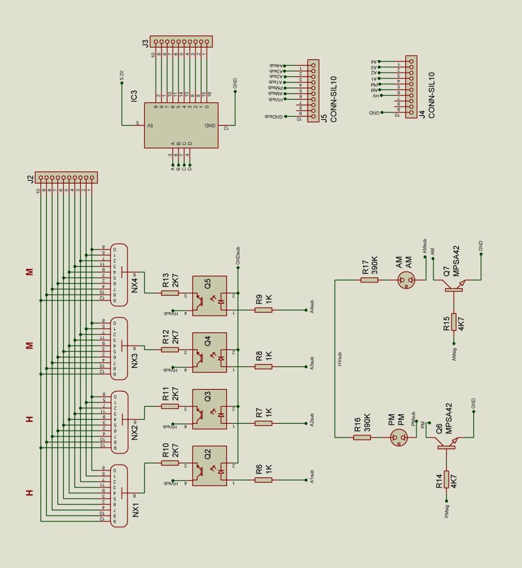
21 6. CIRCUIT DIAGRAM
22 - 22 -
Nixie Clock Type Quattro'
 Assembly Instructions And User Guide Nixie Clock Type Quattro' - 1 - Issue Number Date REVISION HISTORY 2 8 Sept 2012 Errors corrected 1 27 July 2012 New document Reason for Issue - 2 - 1.1 Nixie Quattro
Nixie Clock Type Frank 2 Z570M
 Assembly Instructions And User Guide Nixie Clock Type Frank 2 Z570M Software version: 7R PCB Revision: 11 April 09-1 - 1. INTRODUCTION 1.1 About the clock Nixie clock type Frank 2 is a compact design with
SN-Class Nixie Clock Kits
 Assembly Instructions And User Guide SN-Class Nixie Clock Kits - 1 - REVISION HISTORY Issue Date Reason for Issue Number 1 20 November 2017 New document - 2 - 1. INTRODUCTION 1.1 About the How can the
Nixie Clock Type Frank 3
 Assembly Instructions And User Guide Nixie Clock Type Frank 3 Software version: 7R PCB Version: 11 April 09-1 - 1. INTRODUCTION 1.1 About the clock Nixie clock type Frank 3 is a compact design with all
Nixie Tube Clock Type Marsden
 Assembly Instructions And User Guide Nixie Tube Clock Type Marsden Software version: RTC-1.3 PCB Revision: 16 Aug 10-1 - 1. INTRODUCTION 1.1 About the clock Nixie clock type Marsden is a compact design
Nixie Clock Type SixNix
 Assembly Instructions And User Guide Nixie Clock Type SixNix - 1 - Issue Number Date REVISION HISTORY Reason for Issue 6 20 March 2014 Removed WWVB Support 5 14 July 2012 New Board Issue - 19 July 12 4
Nixie Clock Type IN-8 & NL840 Nixie'
 Assembly Instructions And User Guide Nixie Clock Type IN-8 & NL840 Nixie' - 1 - REVISION HISTORY Issue Number Date 4 15 December 2016 New diode for D2 3 30 August 2014 Typos 2 25 June 2014 Added NL840
Nixie Clock Type Frank 3'
 Assembly Instructions And User Guide Nixie Clock Type Frank 3' - 1 - REVISION HISTORY Issue Number Date Reason for Issue 4 16 December 2016 New diode for D2 3 12 November 2012 Improved first clock test
Nixie Clock Type Nixie Maestro
 Assembly Instructions and User Guide Nixie Clock Type Nixie Maestro - 1 - Issue Number Date REVISION HISTORY Reason for Issue 4 01 April 2017 New version with neons for AM / PM 3 10 December 2014 Typing
Assembly Instructions And User Guide. Elite Nixie. Nixie Tube Clock Elite Issue 2 (07 June 2018)
") Assembly Instructions And User Guide Elite Nixie - 1 - REVISION HISTORY Issue Number Date Reason for Issue 2 07 June 2018 Added more NL840 details 1 04 May 2018 New document - 2 - 1. INTRODUCTION Here
Assembly Instructions And User Guide Elite Nixie - 1 - REVISION HISTORY Issue Number Date Reason for Issue 2 07 June 2018 Added more NL840 details 1 04 May 2018 New document - 2 - 1. INTRODUCTION Here
Nixie Clock Type Nixie QTC
 Assembly Instructions And User Guide Nixie Clock Type Nixie QTC - 1 - REVISION HISTORY Issue Number Date Reason for Issue 12 10 September 2015 C6 changed to 33pF 11a 11 December 2014 C5 changed to 10pF.
Nixie Clock Type Nixie QTC Plus
 Assembly Instructions And User Guide Nixie Clock Type Nixie QTC Plus - 1 - REVISION HISTORY Issue Date Number Draft 1 29 August 2018 New document Reason for Issue - 2 - 1. INTRODUCTION 1.1 Nixie QTC Plus
Nixie Clock Kit V1.08 Assembly and Operation
 Nixie Clock Kit V1.08 Assembly and Operation Hardware Revision 14.05.2005 Software Version 6.0 Revision 19.04.2006 This document is copyrighted. No parts of this documentation may be used commercially.
Documentation VFD clock 8 a clock
 Documentation VFD clock 8 a clock This documentation is protected by our copyright. It must not be used for commercial purposes. Congratulations on your purchase of your VFD clock. To guarantee success
Bill of Materials: Super Simple Water Level Control PART NO
 Super Simple Water Level Control PART NO. 2169109 Design a simple water controller in which electrodes are required to sense high and low water levels in a tank. Whenever the water level falls below the
Introduction 1. Green status LED, controlled by output signal ST. Sounder, controlled by output signal Q6. Push switch on input D6
 Introduction 1 Welcome to the GENIE microcontroller system! The activity kit allows you to experiment with a wide variety of inputs and outputs... so why not try reading sensors, controlling lights or
VU-1 VU Meter Kit Volume Unit Meter
 VU-1 VU Meter Kit Volume Unit Meter Simplicity Counts, Detail Matters. No part of this document may be reproduced, either mechanically or electronically, posted online on the Internet, in whole or in part,
Nixie Clock Kit IN-12B color LED backlit Operation Manual Nixie Clock Kit IN-12B V6.0 ( All Right Reserved 2015 )
") Nixie Clock Kit IN-B color LED backlit Operation Manual Nixie Clock Kit IN-B V. ( All Right Reserved ) - - Operation Manual IN-B Nixie Clock Power for your Nixie Clock The clock does not include a wall
Nixie Clock Kit IN-B color LED backlit Operation Manual Nixie Clock Kit IN-B V. ( All Right Reserved ) - - Operation Manual IN-B Nixie Clock Power for your Nixie Clock The clock does not include a wall
DIY KIT MHZ 8-DIGIT FREQUENCY METER
 This kit is a stand-alone frequency meter capable of measuring repetitive signals up to a frequency of 50MHz. It has two frequency ranges (15 and 50 MHz) as well as two sampling rates (0.1 and 1 second).
7 SEGMENT LED DISPLAY KIT
 ESSENTIAL INFORMATION BUILD INSTRUCTIONS CHECKING YOUR PCB & FAULT-FINDING MECHANICAL DETAILS HOW THE KIT WORKS CREATE YOUR OWN SCORE BOARD WITH THIS 7 SEGMENT LED DISPLAY KIT Version 2.0 Which pages of
Introduction 1. Digital inputs D6 and D7. Battery connects here (red wire to +V, black wire to 0V )
") Introduction 1 Welcome to the magical world of GENIE! The project board is ideal when you want to add intelligence to other design or electronics projects. Simply wire up your inputs and outputs and away
Introduction 1 Welcome to the magical world of GENIE! The project board is ideal when you want to add intelligence to other design or electronics projects. Simply wire up your inputs and outputs and away
MAKE AN RGB CONTROL KNOB.
 MAKE AN RGB CONTROL KNOB. This is a knob based colour changing controller that uses a custom programmed microcontroller to pack a lot of features into a small affordable kit. The module can drive up to
Mal-2 assembly guide v1.0
 Mal-2 assembly guide v.0 SONIC POTIONS Schematic and BOM The BOM can be found on Google Docs Prepare the PCB Separate the PCBs using some pliers. PCB We start with the lower PCB and assemble it beginning
COLOUR CHANGING USB LAMP KIT
 TEACHING RESOURCES SCHEMES OF WORK DEVELOPING A SPECIFICATION COMPONENT FACTSHEETS HOW TO SOLDER GUIDE SEE AMAZING LIGHTING EFFECTS WITH THIS COLOUR CHANGING USB LAMP KIT Version 2.1 Index of Sheets TEACHING
Introduction 1. Green status LED, controlled by output signal ST
 Introduction 1 Welcome to the magical world of GENIE! The project board is ideal when you want to add intelligence to other design or electronics projects. Simply wire up your inputs and outputs and away
Tube Cricket Build Guide
 Tube Cricket Build Guide The Tube Cricket is a small-wattage amp that puts out about 1 watt of audio power. With a 12AU7 tube-preamp and a JRC386 power amp, the Tube Cricket gives you great tone in a compact
ELECTRONIC GAME KIT TEACHING RESOURCES. Version 2.0 BUILD YOUR OWN MEMORY & REACTIONS
 TEACHING RESOURCES SCHEMES OF WORK DEVELOPING A SPECIFICATION COMPONENT FACTSHEETS HOW TO SOLDER GUIDE BUILD YOUR OWN MEMORY & REACTIONS ELECTRONIC GAME KIT Version 2.0 Index of Sheets TEACHING RESOURCES
DIY Guide - Building Franky v1.1, the SEGA Audio and Videocard for MSX
 DIY Guide - Building Franky v1.1, the SEGA Audio and Videocard for MSX 2015 FRS & MSXpró. Translation by FRS and Supersoniqs. Table of Contents Introduction... 3 Materials needed... 3 Audio volume boost...
DDS VFO CONSTRUCTION MANUAL. DDS VFO Construction Manual Issue 1.1 Page 1
 DDS VFO CONSTRUCTION MANUAL DDS VFO Construction Manual Issue 1.1 Page 1 Important Please read before starting assembly STATIC PRECAUTION The DDS VFO kit contains the following components which can be
Christmas LED Snowflake Project
 Christmas LED Snowflake Project Version 1.1 (01/12/2008) The snowflake is a follow-on from my Christmas star project from a few years ago. This year I decided to make a display using only white LEDs, shaped
QUIZ BUZZER KIT TEACHING RESOURCES. Version 2.0 WHO ANSWERED FIRST? FIND OUT WITH THIS
 TEACHING RESOURCES SCHEMES OF WORK DEVELOPING A SPECIFICATION COMPONENT FACTSHEETS HOW TO SOLDER GUIDE WHO ANSWERED FIRST? FIND OUT WITH THIS QUIZ BUZZER KIT Version 2.0 Index of Sheets TEACHING RESOURCES
GUIDE TO ASSEMBLY OF ERICA SYNTHS DELAY MODULE
 If you are reading this, most probably, you are about to build Erica Synths DIY DELAY module. The module is 4mm deep, skiff friendly, has solid mechanical construction and doesn t require wiring. Erica
16 Stage Bi-Directional LED Sequencer
 16 Stage Bi-Directional LED Sequencer The bi-directional sequencer uses a 4 bit binary up/down counter (CD4516) and two "1 of 8 line decoders" (74HC138 or 74HCT138) to generate the popular "Night Rider"
Arduino Nixie Clock Classic Rev4 and Rev5 All In One Modular Rev2
 Arduino Nixie Clock Classic Rev4 and Rev5 All In One Modular Rev2 Operating Instructions Firmware V47 Supported Models: Classic Rev4 Classic Rev5 Modular Rev2 All-In-One NixieClockUserManualV47 About this
TECHNOLOGY WILL SAVE US: THE LUMIPHONE
 TECHNOLOGY WILL SAVE US: THE LUMIPHONE This is a step-by-step guide to soldering your own Lumiphone. The equipment you should have at your station: goggles, soldering mat, soldering Iron, solder and side
VU Meter Buffer DIY Kit
 VU Meter Buffer DIY Kit Warning This document is distributed for educational purposes only. This equipment operates at potentially lethal voltages. Only trained, qualified personnel should operate, maintain,
Multi-Key v2.4 Multi-Function Amplifier Keying Interface
 Multi-Key v2.4 Multi-Function Amplifier Keying Interface ASSEMBLY & OPERATION INSTRUCTIONS INTRODUCTION The Harbach Electronics, LLC Multi-Key is a multi-function external device designed for the safe
MONO AMPLIFIER KIT ESSENTIAL INFORMATION. Version 2.2 CREATE YOUR OWN SPEAKER DOCK WITH THIS
 ESSENTIAL INFORMATION BUILD INSTRUCTIONS CHECKING YOUR PCB & FAULT-FINDING MECHANICAL DETAILS HOW THE KIT WORKS CREATE YOUR OWN SPEAKER DOCK WITH THIS MONO AMPLIFIER KIT Version 2.2 Build Instructions
Arduino Nixie Clock Classic Rev4 and Rev5 All In One
 Arduino Nixie Clock Classic Rev4 and Rev5 All In One Operating Instructions Firmware V52 Supported Models: Classic Rev4 Classic Rev5 All-In-One NixieClockUserManualV52 About this document This is the user
Arduino Nixie Clock Modular Rev3
 Arduino Nixie Clock Modular Rev3 Operating Instructions Firmware V348 Supported Models: Modular Revision 3 NixieClockUserManualV348 About this document This is the user instruction manual for the Nixie
ADD AN AUDIO MESSAGE TO YOUR PRODUCT WITH THIS RECORD & PLAYBACK KIT
 ADD AN AUDIO MESSAGE TO YOUR PRODUCT WITH THIS RECORD & PLAYBACK KIT BUILD INSTRUCTIONS Before you start take a look at the Printed Circuit Board (PCB). The components go in the side with the writing on
Total solder points: 123 Difficulty level: beginner 1. advanced AUDIO ANALYZER K8098. audio gea Give your. . high-tech ILLUSTRATED ASSEMBLY MANUAL
 Total solder points: 123 Difficulty level: beginner 1 2 3 4 5 advanced AUDIO ANALYZER K8098 ra audio gea Give your. look high-tech ILLUSTRATED ASSEMBLY MANUAL H8098IP-1 Features & Specifications Features
8 PIN PIC PROGRAMMABLE BOARD (DEVELOPMENT BOARD & PROJECT BOARD)
") ESSENTIAL INFORMATION BUILD INSTRUCTIONS CHECKING YOUR PCB & FAULT-FINDING MECHANICAL DETAILS HOW THE KIT WORKS LEARN ABOUT PROGRAMMING WITH THIS 8 PIN PIC PROGRAMMABLE BOARD (DEVELOPMENT BOARD & PROJECT
ESSENTIAL INFORMATION BUILD INSTRUCTIONS CHECKING YOUR PCB & FAULT-FINDING MECHANICAL DETAILS HOW THE KIT WORKS LEARN ABOUT PROGRAMMING WITH THIS 8 PIN PIC PROGRAMMABLE BOARD (DEVELOPMENT BOARD & PROJECT
Analog Style LED Clock
 Analog Style LED Clock Operation and Assembly Manual For use with PCB Rev 2.1 Copyright 2018 All Rights Reserved. Manual version 2.1c, for use with PCB revision 2.1, Software version 2.0.0. The electronic
N3ZI Digital Dial Manual For kit with Backlit LCD Rev 4.00 Jan 2013 PCB
 N3ZI Digital Dial Manual For kit with Backlit LCD Rev 4.00 Jan 2013 PCB Kit Components Item Qty Designator Part Color/Marking PCB 1 LCD Display 1 LCD 1602 Volt Regulator 1 U1 78L05, Black TO-92 Prescaler
TKEY-K16. Touch CW automatic electronic keyer. (No moving parts no contacts) Assembly manual. Last review: March 15, 2018
 Assembly manual. Last review: March 15, 2018") TKEY-K16 Touch CW automatic electronic keyer (No moving parts no contacts) Assembly manual Last review: March 15, 2018 Commands and use manual of the K16 and Updates and news: www.ea3gcy.com Thanks for
TKEY-K16 Touch CW automatic electronic keyer (No moving parts no contacts) Assembly manual Last review: March 15, 2018 Commands and use manual of the K16 and Updates and news: www.ea3gcy.com Thanks for
Industrial Monitor Update Kit
 Industrial Monitor Update Kit (Bulletin Number 6157) Installation Instructions 2 Table of Contents Table of Contents Industrial Monitor Update Kit... 3 Overview... 3 Part 1 - Initial Preparation... 5 Part
Bill of Materials: Magic Color PART NO
 Magic Color PART NO. 2193838 Magic color is a guessing game. With this game you can surprise your friends and leave them with amazement, how the game guesses what they have in their minds. Only two selections
Build A Video Switcher
 Build A Video Switcher VIDEOSISTEMAS serviciotecnico@videosistemas.com www.videosistemas.com Reprinted with permission from Electronics Now Magazine September 1997 issue Copyright Gernsback Publications,
DL-1A. RF dummy load - 50Ω 20W. Assembly manual. Last update: May 1, Thank you for constructing the DL-1A dummy load kit
 DL-1A RF dummy load - 50Ω 20W Assembly manual Last update: May 1, 2016 ea3gcy@gmail.com Updates and news at: www.qsl.net/ea3gcy Thank you for constructing the DL-1A dummy load kit Have fun assembling it
MAIN PCB (The small one) OPEN MAIN BOARD BAG A
 OPEN MAIN BOARD BAG A") THANKS FOR CHOOSING ONE OF OUR KITS! This manual has been written taking into account the common issues that we often find people experience in our workshops. The order in which the components are placed
THANKS FOR CHOOSING ONE OF OUR KITS! This manual has been written taking into account the common issues that we often find people experience in our workshops. The order in which the components are placed
RECORD & PLAYBACK KIT
 TEACHING RESOURCES SCHEMES OF WORK DEVELOPING A SPECIFICATION COMPONENT FACTSHEETS HOW TO SOLDER GUIDE ADD AN AUDIO MESSAGE TO YOUR PRODUCT WITH THIS RECORD & PLAYBACK KIT Version 2.1 Index of Sheets TEACHING
The NorCal SMT Dummy Load Assembly and Operating Manual Rev. 1.0 January 4, 2005
 The NorCal SMT Dummy Load Assembly and Operating Manual Rev. 1.0 January 4, 2005 Copyright 2005 W3CD 1 1. Introduction The NorCal SMT Dummy Load is a practice kit for anyone wishing to gain some experience
Arduino Modular IN-14 Nixie Clock Rev2 V45 All-In-One Modular Clock Operating Instructions & Construction Manual
 Arduino Modular IN-14 Nixie Clock Rev2 V45 All-In-One Modular Clock Operating Instructions & Construction Manual NixieClockModularInstructionManualRev2V45 Contact Information If you want to get in contact
N3ZI Digital Dial Manual For kit with Serial LCD Rev 3.04 Aug 2012
 N3ZI Digital Dial Manual For kit with Serial LCD Rev 3.04 Aug 2012 Kit properly assembled and configured for Standard Serial LCD (LCD Not yet connected) Kit Components Item Qty Designator Part Color/Marking
Arduino IN-14 Nixie Clock v42 All-In-One Clock Operating Instructions & Construction Manual
 Arduino IN-14 Nixie Clock v42 All-In-One Clock Operating Instructions & Construction Manual NixieClockIN14InstructionManualRev2V42 Contact Information If you want to get in contact with us, please email
Lab 7: Soldering - Traffic Light Controller ReadMeFirst
 Lab 7: Soldering - Traffic Light Controller ReadMeFirst Lab Summary The two-way traffic light controller provides you with a quick project to learn basic soldering skills. Grading for the project has been
Arduino Nixie Clock Modular Rev3
 Arduino Nixie Clock Modular Rev3 Operating Instructions Firmware V352 Supported Models: Modular Revision 3 NixieClockUserManualV352 About this document This is the user instruction manual for the Nixie
Digital Clock. Perry Andrews. A Project By. Based on the PIC16F84A Micro controller. Revision C
 Digital Clock A Project By Perry Andrews Based on the PIC16F84A Micro controller. Revision C 23 rd January 2011 Contents Contents... 2 Introduction... 2 Design and Development... 3 Construction... 7 Conclusion...
Total solder points: 117 Difficulty level: beginner advanced. RGB Controller K8088 ILLUSTRATED ASSEMBLY MANUAL
 Total solder points: 117 Difficulty level: beginner 1 2 3 4 5 advanced RGB Controller K8088 Control incandescent bulbs, LEDs, common anode led strips, etc... ILLUSTRATED ASSEMBLY MANUAL H8088IP-1 Features
Timer Modules. EL11 24 Hour Module EL17 7 Day Module. Installation & Operating Instructions
 Timer Modules EL11 24 Hour Module EL17 7 Day Module Installation & Operating Instructions 1 1. General Information These instructions should be read carefully and retained for further reference and maintenance.
Thank you for purchasing this product. If installing for someone else, please ensure that the instructions are handed to the householder.
 Instruction Manual TPSE201 (181422) - BOSS TM Universal Programmer TPSE101 (569565) - BOSS TM Universal Timeswitch Thank you for purchasing this product. If installing for someone else, please ensure that
Installing The PK-AM keyer and. from Jackson Harbor Press Operating: A Morse code keyer chip with pot speed control
 Installing The PK-AM keyer and from Jackson Harbor Press Operating: A Morse code keyer chip with pot speed control The PK-AM keyer is a modification for the PK-AM kit, it changes the AM transmitter to
Parts Checklist - Please note there is no resistor R3. Diodes, LED and transistors are polarized see construction stages
 Xtal Check Kit build Read me first! -------- UPDATED GUIDE------ September 12, 2018--------- The following steps are designed to get your Xtal check kit built and operational. This is a good beginner s
Timer Modules. MEU11 24 Hour Module, MEU17 7 Day Module (Without Housing)
") Timer Modules MEU11 24 Hour Module, MEU17 7 Day Module (Without Housing) EMU11 24 Hour Module, EMU17 7 Day Module (With Housing Giving panel mounting facility) Installation & Operating Instructions 1 1.
Timer Modules MEU11 24 Hour Module, MEU17 7 Day Module (Without Housing) EMU11 24 Hour Module, EMU17 7 Day Module (With Housing Giving panel mounting facility) Installation & Operating Instructions 1 1.
FSM User Guide Page 1 of 28
 FSM User Guide Page 1 of 28 Field Strength Meter User Guide and Kit Assembly Instructions PCB V1.1 Important: Always use or print this document in colour as there are references to the colours of components.
Ten-Tec (865) Service Department:(865)
 Service Department:(865)") Ten-Tec (865) 453-7172 Service Department:(865) 428-0364 Installation Instructions for Ten-Tec Jupiter AT538K Tuner Kit The installation of the AT538K is divided into two steps. The first step is to reprogram
Ten-Tec (865) 453-7172 Service Department:(865) 428-0364 Installation Instructions for Ten-Tec Jupiter AT538K Tuner Kit The installation of the AT538K is divided into two steps. The first step is to reprogram
research platform comma.ai, github.com/commaai/neo
 neo research platform comma.ai github.com/commaai/neo 1 suppliers 2 electronics 1. download digikey.csv 2. go to digikey.com/classic/ordering and register or log in 3. click and navigate to the downloaded
Modellbahn Digital Peter Stärz
 Modellbahn Digital Peter Stärz Dresdener Str. 68 D-02977 Hoyerswerda +49 3571 404027 www.firma-staerz.de info@firma-staerz.de 8-fold Track Occupancy Detector for digital systems with two-wire track (e.g.
Fixed Audio Output for the K2 Don Wilhelm (W3FPR) & Tom Hammond (NØSS) v August 2009
 & Tom Hammond (NØSS) v August 2009") Fixed Audio Output for the K2 Don Wilhelm (W3FPR) & Tom Hammond (NØSS) v. 2.1 06 August 2009 I have had several requests to provide a fixed audio output from the K2. After looking at the circuits that
Fixed Audio Output for the K2 Don Wilhelm (W3FPR) & Tom Hammond (NØSS) v. 2.1 06 August 2009 I have had several requests to provide a fixed audio output from the K2. After looking at the circuits that
SceneStyle2 User Guide
 SceneStyle2 User Guide Mode Lighting (UK) Limited. The Maltings, 63 High Street, Ware, Hertfordshire, SG12 9AD, UNITED KINGDOM. Telephone: +44 (0) 1920 462121 Facsimile: +44 (0) 1920 466881 e-mail: website:
Lab 7: Soldering - Traffic Light Controller ReadMeFirst
 Lab 7: Soldering - Traffic Light Controller ReadMeFirst Lab Summary The two way traffic light controller provides you with a quick project to learn basic soldering skills. Grading for the project has been
Azatrax Model Railroad Track Signal Control - Single Track
 Installation Guide Azatrax Model Railroad Track Signal Control - Single Track TS2 What it is: The TS2 operates one or two trackside block signals (one in each direction) on one track to simulate the block
STROBOSCOPE LIGHT EFFECT KIT
 STROBOSCOPE LIGHT EFFECT KIT Easy to build stroboscope for general applications Flash frequency: 5 to 15 flashes per second Power supply: 110VAC Power consumption: 13W max. PCB dimensions: 50 x 75mm modifications
Operating Manual. Basic Control BC16. two-channel for eco moon
 Operating Manual Basic Control BC16 two-channel for eco moon Dear Customer, Thank you for choosing a WALTRON daytime lighting controller. Your daytime lighting controller is a high-quality product that
"shell" digital storage oscilloscope (Beta)
") "shell" digital storage oscilloscope (Beta) 1. Main board: solder the element as the picture shows: 2. 1) Check the main board is normal or not Supply 9V power supply through the connector J7 (Note: The
"shell" digital storage oscilloscope (Beta) 1. Main board: solder the element as the picture shows: 2. 1) Check the main board is normal or not Supply 9V power supply through the connector J7 (Note: The
Color Organ Triple Deluxe II.
 http://wwwinstructablescom/id/color-organ-triple-deluxe-ii/ Food Living Outside Play Technology Workshop Color Organ Triple Deluxe II by ledartist on January 13, 2013 Table of Contents Color Organ Triple
Dust Sensor using GP Y
 Dust Sensor using GP Y Dust sensors detect fine dust ( aerosol ) floating in the air. They are used to determine air quality indoor and outdoor. Limits of the GP2Y10 The GP2Y10 sensor was developed to
WiFi Time Provider v1 for Arduino Nixie Clock Operating Instructions & Construction Manual
 WiFi Time Provider v1 for Arduino Nixie Clock Operating Instructions & Construction Manual Document V001c Contact Information If you want to get in contact with us, please email to: nixie@protonmail.ch
POINTS POSITION INDICATOR PPI4
 POINTS POSITION INDICATOR PPI4 Monitors the brief positive operating voltage across points motors when they are switched Lights a corresponding led on a control panel to show the last operation of each
SINGLE ZONE CLIMATE ZONING SYSTEM. Technical Manual. Polyaire Pty Ltd
 SINGLE ZONE CLIMATE ZONING SYSTEM Technical Manual Polyaire Pty Ltd 11-13 White Road GEPPS CROSS South Australia, 5094 Tel: (08) 8349 8466 Fax: (08) 8349 8446 www.polyaire.com.au CONTENTS Features 1 Application
Minimising the tuning drift effects due to external temperature variations in the Titanium Satellite C1W-PLL Wideband LNBF
 Minimising the tuning drift effects due to external temperature variations in the Titanium Satellite C1W-PLL Wideband LNBF Although the Titanium LNB is named in the header, the comments which follow obviously
Reaction Game Kit MitchElectronics 2019
 Reaction Game Kit MitchElectronics 2019 www.mitchelectronics.co.uk CONTENTS Schematic 3 How It Works 4 Materials 6 Construction 8 Important Information 9 Page 2 SCHEMATIC Page 3 SCHEMATIC EXPLANATION The
XTAL Bank DDS Version 0.02 Sept Preliminary, highly likely to contain numerous errors
 XTAL Bank DDS Version 002 Sept 7 2012 Preliminary, highly likely to contain numerous errors The photo above shows the fully assembled Xtal Bank DDS with 2 DDS modules installed (The kit is normally only
Australian Technical Production Services
 Australian Technical Production Services Dual Rail Crowbar Copyright notice. These notes, the design, schematics and diagrams are Copyright Richard Freeman, 2015 While I am happy for the notes to be printed
Galilean Moons. dual amplitude transmutator. DIY ASSEMBLY MANUAL v1.02
 Galilean Moons dual amplitude transmutator DIY ASSEMBLY MANUAL v1.02 Contents Contents... 2 Introduction... 3 Eurorack Kit Assembly... 4 Resistors... 4 IC Sockets... 5 Ceramic/Film Capacitors... 5 Transistors
INTRODUCTION (EE2499_Introduction.doc revised 1/1/18)
") INTRODUCTION (EE2499_Introduction.doc revised 1/1/18) A. PARTS AND TOOLS: This lab involves designing, building, and testing circuits using design concepts from the Digital Logic course EE-2440. A locker
INTRODUCTION (EE2499_Introduction.doc revised 1/1/18) A. PARTS AND TOOLS: This lab involves designing, building, and testing circuits using design concepts from the Digital Logic course EE-2440. A locker
RD RACK MOUNT DIMMER OWNERS MANUAL VERSION /09/2011
 RD - 122 RACK MOUNT DIMMER OWNERS MANUAL VERSION 1.3 03/09/2011 Page 2 of 14 TABLE OF CONTENTS UNIT DESCRIPTION AND FUNCTIONS 3 POWER REQUIREMENTS 3 INSTALLATION 3 PLACEMENT 3 POWER CONNECTIONS 3 OUTPUT
CLF Manuals CLF Colour Par CLF Colour 12 Par CLF Colour Par 12 Version 1.0 November 2012 Version 1.0 1
 CLF Manuals CLF Colour Par 12 CLF Colour Par 12 Version 1.0 November 2012 1 1.BEFORE YOU BEGIN What is included Ø 1 x Fixture Ø 1 x Power cable with plug Ø 1 x User Manua Unpacking Instructions Immediately
VK-P10SE WARRANTY REGISTRATION FORM
 VK-P10SE WARRANTY REGISTRATION FORM Unit Serial Number: Customer Name: Address: Date of Purchase: Purchased From: Dealer Name: Address: IMPORTANT NOTE: In order to receive the full five-year product warranty,
EPROM pattern generator with "Genlock"
 EPROM pattern generator with "Genlock" This generator uses an EPROM to store several pictures that can then be selected by means of a thumb-wheel switch. Alternatively, if the pictures stored are in a
This Unit may form part of a National Qualification Group Award or may be offered on a free standing basis.
 National Unit Specification: general information CODE F5JJ 11 SUMMARY The Unit is intended for candidates with little or no prior knowledge of Analogue or Digital Electronic Circuits. It provides an opportunity
NewScope-7A Operating Manual
 2016 SIMMCONN Labs, LLC All rights reserved NewScope-7A Operating Manual Preliminary May 13, 2017 NewScope-7A Operating Manual 1 Introduction... 3 1.1 Kit compatibility... 3 2 Initial Inspection... 3 3
ELECTRONIC GAME KIT ESSENTIAL INFORMATION. Version 2.0 BUILD YOUR OWN MEMORY & REACTIONS
 ESSENTIAL INFORMATION BUILD INSTRUCTIONS CHECKING YOUR PCB & FAULT-FINDING MECHANICAL DETAILS HOW THE KIT WORKS BUILD YOUR OWN MEMORY & REACTIONS ELECTRONIC GAME KIT Version 2.0 Build Instructions Before
NCV NIXIE CLOCK
 NCV3.1-16 NIXIE CLOCK Assembling manual & user's guide UG-02-16-REV-E FW-REV-02 This page intentionally left blank 1. Introduction TubeHobby congratulates you on your choice and wishes enjoyable assembling
Aspect 2 Circuit Digital Scene Control
 Aspect 2 Circuit Digital Scene Control S p e c i f i c a t i o n 2 circuits of trailing edge dimming 500W total between the two circuits Both circuits feature independent overload, short-circuit and open-circuit
Part No. ENC-LAB01 Users Manual Introduction EncoderLAB
 PCA Incremental Encoder Laboratory For Testing and Simulating Incremental Encoder signals Part No. ENC-LAB01 Users Manual The Encoder Laboratory combines into the one housing and updates two separate encoder
While the parts are already inventoried at the factory, please verify the inventory check as you go:
 Thank you for purchasing the kit for building the WJ9J DTMF controller. After building, you should read the document on operation (WJ9JDTMFControllerV5.pdf) in order to use. This is also in the link in
INSTALLATION & USER GUIDE
 INSTALLATION & USER GUIDE Digidim 458 8-Channel Dimmer STEP 1 Assemble Dimmer Unit STEP 2 Mount Dimmer Chassis STEP 3 Electrical Installation STEP 4 Attach Module and Make Connections STEP 5 Replace Cover
Digital Economy Seven Programmer
 Digital Economy Seven Programmer Model: TRTD7N White Installation & Operating Instructions 1. General Information These instructions should be read carefully and retained for further reference and maintenance.