OTS-1L Optiva L-band Transmission System Installation Manual
|
|
|
- Homer Nicholson
- 5 years ago
- Views:
Transcription


1 OTS1L Optiva Lband Transmission System Installation Manual MANOTS1L, Rev C
2 OTS1L series Table of Contents General... 3 Interface and Controls... 4 Transmitter... 4 Receiver... 5 Installation... 6 Operation... 6 Peak Signal Optimizer Gain Control Mode (PEAK)(TX)... 6 Smart Gain Control Mode (SGC)(TX)... 6 Manual Gain Control Mode (MGC)(TX)... 7 LED Indicator Tables & Diagram... 7 Remote Monitoring... 8 Simple Network Management Protocol (SNMP)... 8 Specifications... 9 Ordering Information... 9 Optics Handling & Safety Warranty EMCORE Corporation offers a broad portfolio of compound semiconductorbased components and systems for the broadband, fiber optic, satellite communication, defense and solar power markets. EMCORE has two primary operating segments: Fiber Optics and Photovoltaics. The company s integrated solutions philosophy embodies stateoftheart technology, material science expertise, and a shared vision of our customer s goals and objectives to be leaders in fiber optics and photovoltaics. EMCORE s solutions include: optical components and subsystems for fibertothepremise, cable television, high speed data and telecommunication networks; defense photonics products for commercial and military applications including lasers, modulators, spectrometers, sensors, fiber gyro components and diagnostic instruments; solar cells, solar panels, and fiber optic ground station links for global satellite communications Chestnut Street Alhambra, California 91803, USA (626) Fax: (626) MANOTS1L, Rev C Page 2 of 12
 eliminating external power insertion equipment Highdynamicrange, opticallyisolated DFB lasers 50 Ohm or 75 Ohm")
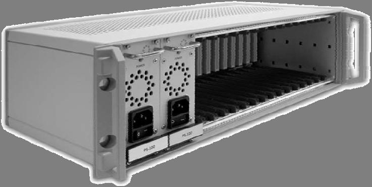
3 OTS1L series General Fully compatible with Optiva multi platform enclosures, providing RF, video, audio and data links. 16 Mix and match slots per chassis with redundant power supply LNB Power (off or 17V) eliminating external power insertion equipment Highdynamicrange, opticallyisolated DFB lasers 50 Ohm or 75 Ohm versions Smart RF gain control (SGC) optimizes for consistent performance over a wide input range Manual gain control (MGC) override Multiple monitoring and control options provide for panel LED, SMA, & digital SNMP monitoring Optiva Lband fiber optic intrafacility links are a highperformance, costeffective alternative to coaxial cable. They provide much longer transmission distances than copper cables, which simplify network design, ease installation and even enhance immunity from EMI, RFI and lightning. These transmitters and receivers take the best RF design features of Emcore s extensive families of products and combine them into a compact package compatible with the Optiva OTCC16 chassis. The Optiva family s wide range of RF, video, audio and data transport products include a unique data bus design that provides a higher level of monitoring and control with a single chassis mix and match flexibility. The final result is a chassis system that can be factory or user custom configured to meet a wide range of fiber transport applications. All units come as an insert card version. The cards can be inserted into the Optiva 3RU 16slot, 19 rackmountable card cage (OTCC16), 1RU 4slot 19 rack (OTCC41U) or one of the smaller Optiva Desktop Card Racks (OTDTCR Series). The power supply must be the 12 volt version. MANOTS1L, Rev C Page 3 of 12
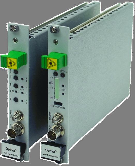
4 OTS1L series Interface and Controls Transmitter Figure Transmitter 1. Out The output of the laser is provided from this SCAPC socket. (see Optics Handling section) 2. STATUS This LED glows green when OK and red when there is a major alarm. 3. RF The illuminated LED color indicates the RF power on the laser. Green is optimum. 4. MGC This LED illuminated indicates manual operation mode. 5. ON/OFF This button will toggle between SGC and MGC mode. 6. LNB This LED illuminated indicates the presence of DC voltage at the RF input connector. 7. MONITOR This connector provides a 32dB representation of the laser input RF. 8. RF IN The RF input signal is applied to this RF connector. 9. PEAK This button will optimize the RF input to the laser while in SGC or MGC mode. 10. H This button increases the RF level approximately 0.5dB per step when in MGC mode (na in SGC). 11. L This button decreases the RF level approximately 1dB per step when in MGC mode (na in SGC) /0 Switching to the 1 position will enable DC voltage to be present at the RF input connector. 13. The chassis retention screws will secure the seated module into the chassis. NOTE: A toothpick or cotton swab end provides a convenient, safe way to access the recessed buttons and switches. For a toothpick, break off the end for a flatter surface. 13 MANOTS1L, Rev C Page 4 of 12
5 OTS1L series Receiver 23 Figure Receiver 14. IN The input optical fiber is inserted into this SCAPC socket. (see Optics Handling section) 15. STATUS This LED illuminated indicates the ON status condition of the module. 16. RF dbm The illuminated LED bar graph indicates the RF output status in four stages. 17. STATUS MONITOR This socket provides a trigger for external monitoring equipment. 18. RF OUT The RF output signal is available at this RF connector. 19. OPTICAL The illuminated LED indicates the presence of fiber optic light. 20. H This button increases the output RF level approximately 1dB per step. 21. L This button decreases the output RF level approximately 1dB per step. 22. MONITOR This connector provides a 25dB representation of the RF output. 23. The chassis retention screws will secure the seated module into the chassis. Status monitor pin details = ground 3= PDI current (0dbmo = 1.15 to 1.2vdc) 2= Unit summary alarm (low state alarm, 3.3vdc normal condition) 1= FUTURE MANOTS1L, Rev C Page 5 of 12
6 OTS1L series Installation Module Installation Align the top and bottom card edges in the chassis channel and slide firmly into the back plane. Tighten the top and bottom module screws to secure in chassis. Transmitter Installation Prior to connecting the input RF connector, ensure that the LNB power switch is in the desired mode and verify with the LNB LED. Refer to figure 1. Connect satellite signal to the RF input connector. Press and release the PEAK button to optimize the RF level to the laser. (Optional.) Insert the SC/APC connector in the fiber output connector socket. (See Optics Handling section.) Receiver Installation Insert the SC/APC connector in the fiber input connector socket. Connect satellite signal output to the RF output connector. Press and release the H/L button to adjust the output RF to the desired level. Reference the LED bar graph to ensure optimized operation. Signal level can be monitored through the provided SMA monitor port. Operation Peak Signal Optimizer Gain Control Mode (PEAK)(TX) The peak button is designed to optimize the RF signal level introduced to the laser. This ensures that the transmitter module is providing the optimum performance. Pressing the PEAK button once causes the circuits to adjust the RF gain up/down automatically to the ideal RF power based on the RF level at that moment. In SGC mode the module will hold this level stable within a window. In MGC mode this feature is only instantaneous and will not adjust for level variances. Smart Gain Control Mode (SGC)(TX) Every step has been taken to ensure simple hands free operation. The Smart Gain Control mode provides for a wide input range optimized to the laser input. Variances to the input RF level are automatically adjusted, but in a unique way to minimize crosstalk between different transponder signals (patent pending). This will provide the lowest possible noise and distortion. The transmitter RF LED indicator will display the input RF status: Red: The Input RF is far above the optimum SGC range. Blinking Green: The Input RF is above the optimum SGC range. Green: The Input RF is within the optimum SGC range. Amber: The Input RF is below the optimum SGC range. Blank: The Input RF is below the detectable range. MANOTS1L, Rev C Page 6 of 12
7 OTS1L series Manual Gain Control Mode (MGC)(TX) The Optiva Lband transmission system is designed to work in a wide frequency spectrum. In the event of the presence of undesired outofband signals that vary greatly in level, or for situations such as uplinks where a very stable gain is introduced, Emcore recommends that the transmitter be placed in MGC. To use MGC mode, on the transmitter press and release the MGC ON/OFF button. The MGC LED indicator will illuminate in MGC mode. Use the H/L buttons to bring the RF level into range. The transmitter RF LED indicator will display green when the input RF is within the optimum range. Alternatively, pressing the PEAK button once will adjust the Tx RF gain for the ideal RF laser power on the laser, based on the RF power into the Tx at that moment. In manual gain control, the gain setting remains constant regardless of the RF input power changes. LED Indicator Tables & Diagram TX Status LED (Table 01) RF STATUS LED, Transmitter LED Transmitter STATUS ALERT Notes Chassis LED, Chassis LED Red Green Blue OFF RF High alarm Green, fast blink Green Blue OFF RF High, warning Green Green Blue OFF Optimum range. (Within SGC locking range.) Amber Green Blue OFF RF Low, warning OFF Green Blue OFF Loss of RF signal Red OFF Red Summary Alarm RX Status LED (Table 02) OPTICAL STATUS Receiver LED Receiver LED STATUS ALERT, Notes Chassis LED Chassis LED Green Green Blue OFF Optimal range Amber Green Blue OFF Low, warning Off Red OFF Red Low, alarm Optiva Lband Fiberoptic Transmission System DC to LNB Tx Rx Sin S L Laser P L Pr Photo diode S p S out Pushbutton Optimizer L opt S mon S mon MANOTS1L, Rev C Page 7 of 12
8 OTS1L series Remote Monitoring Simple Network Management Protocol (SNMP) The Optiva System is designed to provide remote status and control monitoring via SNMP monitoring programs. Use of this feature requires the use of a network management system agent card (NMS) that serves as the interface between the data retrieved from the system cards and the management program. Management Interface Bases (MIB s) are available with the purchase of the NMS card (OPVCTLRIC). The MIB defines the detailed variables and protocol for the particular product. OTS1LT (Transmitter) Monitored Values Laser Bias Optical Power Temperature RF Attenuator Setting RF Power at Laser LNB voltage Summary Alarm RF Alarm Optical Power Alarm Model # Serial # Manufacture date Firmware # Hardware # Controlled Values SGC/MGC mode RF Gain Peak RF power at Laser Low* RF power at Laser Minor Low* RF power at Laser Major Low* RF power at Laser High* RF power at Laser Minor High* RF power at Laser Major High* * Asterisked values are factory set to optimal performance for most satellite signal applications. Consult with Emcore prior to changing. OTS1LR (Receiver) Monitored Values Temperature RF Power Level Photo Diode Current Summary Alarm Power Supply Alarm Photo Diode Alarm Model # Serial # Manufacture date Firmware # Hardware # Controlled Values RF Gain MANOTS1L, Rev C Page 8 of 12
9 OTS1L series Specifications Parameter MIN Typical MAX Units Link Frequency Range 50 Ohm 75 Ohm MHz MHz Fiber Distance 0 20 Km Optical Loss 0 8 dbo Operating Temperature C TX RF Input within SGC Range 0 to 35 dbm TX Gain (TG) at Max, 1GHz 0 8 db (W/A) TG Adjustment Range (Reduction from max) 30 db Noise Figure (TG at max, 2150 MHz, 1dBo loss) db Spur Free Dynamic Range (1 dbo loss) db/hz LNB Voltage Current V ma Optical Power dbmo DC Power LNB Off V ma RX RF Output (Tx at peak, 1 dbm into Rx) 8 to 25 dbm RX Gain (RG), at max, 1 GHz db (A/W) RG Adjustment Range (Reduction from max) 15 db Output IP3 (2150 MHz) dbm Output 1dB compression point (2150 MHz) 15 dbm Optical Input Optimal dbmo dbmo DC Power V ma (1) Link RF Gain db =TG+RG2*FiberLoss dbo (assumes R in =R out ) (2) dbmo & dbo indicate optical power & loss to minimize confusion with RF dbm & db Ordering Information Model Number Description Transmitters OTS1LT/B51303SAIC Transmitter, MHz, BNC, 50 ohm, 1310 nm, 3dBm (min), SCAPC OTS1LT/B71303SAIC Transmitter, MHz, BNC, 75 ohm, 1310 nm, 3dBm (min), SCAPC OTS1LT/S51303SAIC Transmitter, MHz, SMA, 50 ohm, 1310 nm, 3dBm (min), SCAPC OTS1RefT/S51306SAIC Transmitter, 120 MHz, SMA, 50 ohm, 1310 nm, 6dBm (typical), SCAPC Receivers OTS1LR/B5SAIC Receiver, MHz, BNC, 50 ohm, SCAPC OTS1LR/B7SAIC Receiver, MHz, BNC, 75 ohm, SCAPC OTS1LR/S5SAIC Receiver, MHz, SMA, 50 ohm, SCAPC OTS1RefR/S5SAIC Receiver, 120 MHz, SMA, 50 ohm, SCAPC Network Control OPVCTLRIC NMS SNMP Controller Card, MIB software Chassis & Accessories OTCC1601 Optiva chassis 3RU 16 Slot rear access OTCC41U Optiva chassis 1RU 4 Slot OTDTCR1 / 2 Optiva chassis Desktop/wall mount 1 Slot / 2 Slot PS200NA/UK/EU Power Supply for OTCC16 (No. American, United Kingdom, European AC cord) PS9012 Power Supply for OTDTCR Universal AC Adaptor MANOTS1L, Rev C Page 9 of 12
10 OTS1L series Optics Handling & Safety Working with fiber optic cables and interfaces require a clean dust free environment. The optical power is confined in the optical core only a few microns in diameter. Small particles of dust can block the proper transfer of light through the connectors. It is therefore important to keep connectors as clean as possible, and when in doubt of the cleanliness of a connector, clean it prior to inserting into a transmitter or receiver receptacle. A number of events can damage fiber optic connectors. Unprotected connector ends can experience damage by impact, airborne dust particles, or excess humidity or moisture. Never touch the fiber end face of the connector. When cleaning fiber optic connectors use only Industrial grade 99% pure isopropyl alcohol, lensgrade, lintfree tissue, and optionally canned dry air. Alternatively, there are a number of simple, effective products that are specifically designed for cleaning fiber optic connectors. Never look into an illuminated fiber end. Disclaimer Every attempt has been made to make this material complete, accurate and uptodate. Users are cautioned that EMCORE reserves the right to make changes without notice and shall not be held responsible for any damages, including consequential, caused by reliance on the material presented, including, but not limited to, typographical, arithmetical, or listing errors. WARNINGS, CAUTIONS, LIABILITY, WARRANTY AND GENERAL NOTES Safety Considerations When installing or using this product, observe all safety precautions during handling and operation. Failure to comply with the following general safety precautions and with specific precautions described elsewhere in this manual violates the safety standards of the design, manufacture, and intended use of this product. Emcore assumes no liability for the customer's failure to comply with these precautions. The fiberoptic laser transmitter used in Emcore s Optiva link contains a class IIIb laser product as defined by the U.S. Department of Health and Human Services, Public Health Service, Food and Drug Administration. This laser product complies with 21 CFR, Chapter I, Subchapter J of the DHEW standards under the Radiation Control for Health and Safety Act of The laser operates at nominally 1310 nm with less than 30 mw optical output. The typical optical output for this product is less than 10 mw. The protective laser plugin module housing prevents a user from being exposed to hazardous optical output levels. Since there is no human access to the laser output during system operation, no special operator precautions are necessary when fiber is connected to the transmitter and receiver. During installation, service, or maintenance, the service technician is warned to not look directly into the end of the fiber connector or the fiber. The light emitted from the fiberoptic connector or any fiber connected to the transmitter is invisible and may be harmful to the human eye. Use either an infared fluorescent screen or an optical power meter for optical output verification. All handling precautions as outlined by Federal agencies or other authorities of class IIIb lasers must be observed. Do not attempt to modify or to service the laser diode module. Return it to Emcore for service and repair. Contact the Emcore Customer Service Department for a return authorization and further instructions. MANOTS1L, Rev C Page 10 of 12
11 OTS1L series Electrostatic Sensitivity Observe electrostatic precautionary procedures. Semiconductor laser transmitters and receivers provide highly reliable performance when operated in conformity with their intended design. However, a semiconductor laser may be damaged by an electrostatic charge inadvertently imposed by careless handling. Static electricity can be conducted to the laser chip from the center pin of the RF input connector, and through the DC connector pins. When unpacking and otherwise handling the transmitter, follow ESD precautionary procedures including use of grounded wrist straps, grounded workbench surfaces, and grounded floor mats. Exposure to electrostatic charge is greatly reduced after the transmitter or receiver has been installed in an operational circuit. Service Do not attempt to modify or service any part of the system other than in accordance with procedures outlined in this Operation Manual. If the system does not meet its warranted specifications, or if a problem is encountered that requires service, return the apparently faulty plugin or assembly to Emcore for evaluation in accordance with Emcore's warranty policy. When returning a plugin or assembly for service, include the following information: Owner, Model Number, Serial Number, Return Authorization Number (obtained in advance from Emcore's Customer Service Dept.), service required and/or description of the problem encountered. Warranty Emcore warrants to the original purchaser all standard products sold by Emcore to be free of defects in material and workmanship for one (1) year from date of shipment from Emcore. During the warranty period, Emcore's obligation, at our option, is limited to repair or replacement of any product that Emcore proves to be defective. This warranty does not apply to any product that has been subject to alteration, abuse, improper installation or application, accident, electrical or environmental overstress, negligence in use, storage, transportation, or handling. This warranty is the only warranty made by Emcore and is in lieu of all other warranties, expressed or implied, except as to title, and can be amended only by a written instrument signed by an officer of Emcore. Emcore sales agents or representatives are not authorized to make commitments on warranty returns. Limitations of Liabilities Emcore's liability on any claim of any kind, including negligence, for any loss or damage arising from, connected with, or resulting from the purchase order, contract, or quotation, or from the performance or breach thereof, or from the design, manufacture, sale, delivery, installation, inspection, operation or use of any equipment covered by or furnished under this contract, shall in no case exceed the purchase price of the device which gives rise to the claim. EXCEPT AS EXPRESSLY PROVIDED HEREIN, EMCORE MAKES NO WARRANTY OF ANY KIND, EXPRESSED OR IMPLIED, WITH RESPECT TO ANY GOODS, PARTS AND SERVICES PROVIDED IN CONNECTION WITH THIS AGREEMENT INCLUDING, BUT NOT LIMITED TO, THE IMPLIED WARRANTIES OF MERCHANTABILITY AND FITNESS FOR A PARTICULAR PURPOSE. EMCORE SHALL NOT BE LIABLE FOR ANY OTHER DAMAGE INCLUDING, BUT NOT LIMITED TO, INDIRECT, SPECIAL OR CONSEQUENTIAL DAMAGES ARISING OUT OF OR IN CONNECTION WITH MANOTS1L, Rev C Page 11 of 12
12 OTS1L series FURNISHING OF GOODS, PARTS AND SERVICE HEREUNDER, OR THE PERFORMANCE, USE OF, OR INABILITY TO USE THE GOODS, PARTS AND SERVICE. Emcore will not be responsible for loss of output or reduced output of optoelectronic devices if the customer performs chip mounting, ribbon bonding, wire bonding, fiber coupling, fiber connectorization, or similar operations. These processes are critical and may damage the device or may affect the device's output or the fiber output. Emcore test reports or data indicating meantimetofailure, meantimebetweenfailure, or other reliability data are design guides and are not intended to imply that individual products or samples of products will achieve the same results. These numbers are to be used as management and engineering tools, and are not necessarily indicative of expected field operation. These numbers assume a mature design, good parts, and no degradation of reliability due to manufacturing procedures and processes. Emcore is not liable for normal laser output degradation or fiber coupling efficiency degradation over the life of the device. Every attempt has been made to make this material as complete and accurate and up to date. Users are cautioned that Emcore reserves the right to make changes without notice and shall not be held responsible for any damages, including consequential, caused by reliance on the material presented, including, but not limited to, typographical, arithmetical, or listing errors. Copyright 2008 EMCORE Corporation MANOTS1L, Rev C Page 12 of 12
OTS-1Ref Optiva Reference Oscillator Link Installation Manual
 OTS-1Ref Optiva Reference Oscillator Link Installation Manual 12-23-08 Revision A Table of Contents General...3 Interface and Controls...4 Transmitter...4 Receiver...5 Installation...6 Operation...6 Signal
opengear OPG-1L 50 MHz-2.3 GHz
 MODEL opengear OPG-1L 50 MHz-2.3 GHz RF FIBER OPTIC LINK EMCORE s opengear OPG-1L s are optimized to perform in the 50 MHz to 2.3 GHz frequency range providing transparent signal transport for satellite
WiBa OPERATOR S MANUAL
 WiBa OPERATOR S MANUAL 2.7 GHz, Wideband ( WiBa ) Fiberoptic Link Model Description Model Description 10381 Tx, Un-amplified, 10 to 2700 MHz, 50 10481 Rx, 10 to 2700 MHz, 50 10382 Tx, Amplified, 10 to
5100 Series IF Fiber Optic Links
 The 51Series fiberoptic interfacility links (IFLs) are a high performance, costeffective alternative to coaxial cable for 1 MHz to 2 MHz IF \satellite communications applications. Emcore s fiberoptic IFLs,
OPERATOR MANUAL OSD8865 DIGITAL TRIPLE VIDEO FIBER OPTIC RECEIVER
 OPERATOR MANUAL OSD8865 DIGITAL TRIPLE VIDEO FIBER OPTIC RECEIVER INDEX 1 1 TECHNICAL SUMMARY... 4 1.1 BRIEF DESCRIPTION... 4 1.1.1 OVERVIEW... 4 1.1.2 APPLICATIONS... 4 1.1.3 FEATURES AND BENEFITS...
Product Operation Manual
 Product Operation Manual VL-FTX FORWARD TRANSMITTER MODULE Ver 1.1(Doc#01-02-008) VALE SYSTEMS INC. 10400 Overland Road #408 Boise, ID 83709-1449,USA Tel: 208.935.6317Fax: 208.935.6234 All rights reserved
Model /29S RF Splitter
 Instruction Manual Model 1584-29/29S RF Splitter March 2013, Rev. 0 LNB VOLTAGE A B MODEL 1584 COMBINER CROSS TECHNOLOGIES INC. GND+DC ON Data, drawings, and other material contained herein are proprietary
Emcore SITU2831 Externally Modulated RF Amplified Fiber Optic Transmitter and SIRU3000 Fiber Optic Receiver
 PRELIMINARY Applications RF and microwave antenna signal distribution EW Systems Broadband delay-line and signal processing systems Frequency distribution systems Radar system calibration Phased array
IF and L-Band Fiber Optic Links. Performance Highlights
 FSS70F6Twall IF and LBand Fiber Optic Links The fiberoptic interfacility links (IFLs) are a highperformance, costeffective alternative to coaxial cable for 10 MHz to 200 MHz IF and 950 MHz to 2050 MHz
OPERATOR MANUAL OSD351 FIBRE OPTIC CCTV TRANSMITTER CARD
 OPERATOR MANUAL OSD351 FIBRE OPTIC CCTV TRANSMITTER CARD OSD351 FIBRE OPTIC CCTV TRANSMITTER CARD Document No:10103701 PAGE 2 C O N T E N T S 1. TECHNICAL SUMMARY...4 1.1 BRIEF DESCRIPTION...4 1.2 TECHNICAL
Noise Detector ND-1 Operating Manual
 Noise Detector ND-1 Operating Manual SPECTRADYNAMICS, INC 1849 Cherry St. Unit 2 Louisville, CO 80027 Phone: (303) 665-1852 Fax: (303) 604-6088 Table of Contents ND-1 Description...... 3 Safety and Preparation
Model DM8000-U Optical Transmitter Direct Modulation, DWDM, Low Distortion, Wideband
 Model DM8000U Optical Transmitter Direct Modulation, DWDM, Low Distortion, Wideband Applications Video signal distribution to HFC CATV and FTTP nodes 1527 Supports CATV, QAM, and DBS signal carriage Replacement
MENU EXECUTE Shiloh Road Alpharetta, Georgia (770) FAX (770) Toll Free
 FAX (770) Toll Free") Instruction Manual Model 2584-31 Combiner May 2011, Rev. A RF MONITOR GAIN = -15 MENU MODEL 2584 COMBINER CROSS TECHNOLOGIES INC. ALARM REMOTE POWER EXECUTE Data, drawings, and other material contained
Instruction Manual Model 2584-31 Combiner May 2011, Rev. A RF MONITOR GAIN = -15 MENU MODEL 2584 COMBINER CROSS TECHNOLOGIES INC. ALARM REMOTE POWER EXECUTE Data, drawings, and other material contained
CardModule. Reference Manual. Series C DA Channel SDI to CVBS Converter. Version 1.0
 Reference Manual C DA 5005 5 Channel SDI to CVBS Converter Version 1.0 Series 5000 CardModule LYNX Technik AG Brunnenweg 3 D-64331 Weiterstadt Germany www.lynx-technik.com Information in this document
Model 755U Optical Transmitter DWDM, up to 20 km, Low Distortion, Wideband
 Model 755U Optical Transmitter DWDM, up to 20 km, Low Distortion, Wideband Emcore s Model 755U is a directly modulated (DM) DWDM optical transmitter specifically designed for wideband applications that
Instruction Manual Model # Block Upconverter
 Instruction Manual Model 2115-278# Block Upconverter August 2018, Rev. A MODEL 2115 UPCONVERTER CROSS TECHNOLOGIES INC. EXT 10MHZ ALARM POWER Data, drawings, and other material contained herein are proprietary
LEVEL ADJUST POWER Shiloh Road Alpharetta, Georgia (770) FAX (770) Toll Free
 FAX (770) Toll Free") Instruction Manual Model 1200-07 Amplifier September 2010 Rev A MONITOR J1 LEVEL ADJUST POWER MODEL 1200 AMPLIER CROSS TECHNOLOGIES, INC. Data, drawings, and other material contained herein are proprietary
Instruction Manual Model 1200-07 Amplifier September 2010 Rev A MONITOR J1 LEVEL ADJUST POWER MODEL 1200 AMPLIER CROSS TECHNOLOGIES, INC. Data, drawings, and other material contained herein are proprietary
Instruction Manual Model BlockUpconverter
 Instruction Manual Model 2115-55 BlockUpconverter June 2009 - Rev. 0 MODEL 2115 UPCONVERTER CROSS TECHNOLOGIES INC. EXT 10MHZ ALARM POWER Data, drawings, and other material contained herein are proprietary
MWT-FM. Operation Manual. FM Single Channel Transmitter. man_mwtfm.
 MWT-FM FM Single Channel Transmitter Operation Manual man_mwtfm www.myeclubtv.com CONTENTS FCC COMPLIANCE STATEMENT. 3 INDUSTRY CANADA COMPLIANCE 3 MWT-FM ORIENTATION. 4 SAFETY PRECAUTIONS 5 FINDING FM
OptEnet OC48 Regenerator Module User Manual
 OptEnet OC48 Regenerator Module User Manual Content Page INTRODUCTION............................................................................. 1 Revision History........................................................................
TC Mbps - 622Mbps FIBER OPTIC MODE CONVERTER/REPEATER (Rev A0.1) User's Manual
 User's Manual") TC3004 50Mbps - 622Mbps FIBER OPTIC MODE CONVERTER/REPEATER (Rev A0.1) MODEL: S/N: DATE: Notice! Although every effort has been made to insure that this manual is current and accurate as of date of publication,
TC3004 50Mbps - 622Mbps FIBER OPTIC MODE CONVERTER/REPEATER (Rev A0.1) MODEL: S/N: DATE: Notice! Although every effort has been made to insure that this manual is current and accurate as of date of publication,
OTLT / OTLR 3000 Manual. L-Band Fiber Optic Link MHz INSTRUCTION MANUAL
 OTLT / OTLR 3000 Manual L-Band Fiber Optic Link 850-3000 MHz INSTRUCTION MANUAL Phone: (209) 586-1022 (800) 545-1022 Fax: (209) 586-1026 E-Mail: sales@olsontech.com REV. X1 www.olsontech.com 05/12/06 INSTALLATION
L-Band Fiber Optic Link
 One Jake Brown Road Old Bridge, NJ 08857-1000 USA (800) 523-6049 (732) 679-4000 FAX: (732) 679-4353 www.blondertongue.com INSTRUCTION MANUAL L-Band Fiber Optic Link For Direct Broadcast Satellite Distribution
VersiVision. FVTM4BCxA-CE / FVRM4BCxA-CE MULTIPLEXER SYSTEM 4-CHANNELS DIGITALLY ENCODED VIDEO 2-CHANNELS BI-DIRECTIONAL DATA
 VersiVision FVTM4BCxA-CE / FVRM4BCxA-CE MULTIPLEXER SYSTEM 4-CHANNELS DIGITALLY ENCODED VIDEO 2-CHANNELS BI-DIRECTIONAL DATA 4-CHANNELS BI-DIRECTIONAL AUDIO 4-CHANNELS BI-DIRECTIONAL CONTACT CLOSURE 1-CHANNEL
Six-Channel TDM Multiplexers for 3G, HD, SDI, and ASI. Installation and Operations. Manual
 Manual DigiLink DLC156 Function modules Six-Channel TDM Multiplexers for 3G, HD, SDI, and ASI Installation and Operations Manual WWW.ARTEL.COM ii DLC156 Function Modules Installation and Operations Manual
LEVEL ADJUST POWER Shiloh Road Alpharetta, Georgia (770) FAX (770) Toll Free
 FAX (770) Toll Free") Instruction Manual Model 1200-75 Amplifier August 2012, Rev. A LEVEL ADJUST POWER MODEL 1200 AMPLIFIER CROSS TECHNOLOGIES, INC. Data, drawings, and other material contained herein are proprietary to Cross
Instruction Manual Model 1200-75 Amplifier August 2012, Rev. A LEVEL ADJUST POWER MODEL 1200 AMPLIFIER CROSS TECHNOLOGIES, INC. Data, drawings, and other material contained herein are proprietary to Cross
USER INSTRUCTIONS MODEL CSI-200 COAXIAL SYSTEM INTERFACE
 USER INSTRUCTIONS MODEL CSI-200 COAXIAL SYSTEM INTERFACE 9350-7676-000 Rev B, 5/2001 PROPRIETARY NOTICE The RTS product information and design disclosed herein were originated by and are the property of
DVBus and Multiplexer and demultiplexer assemblies for video channels, with bidirectional audio and data USER MANUAL
 DVBus 8350-16 and 8350-4 Multiplexer and demultiplexer assemblies for 16-4 video channels, with bidirectional audio and data USER MANUAL 1. Description. Indicators and system connections DVBus 8350 systems
Gigabit Multi-mode SX to Single Mode LX Converter. User s Manual NGF-728 Series. Warning COPYRIGHT
 COPYRIGHT Gigabit Multi-mode SX to Single Mode LX Converter User s Manual NGF-728 Series All rights reserved. No part of this publication may be reproduced, stored in a retrieval system, or transmitted
Traditional RF Splitter/Combiner and Directional Coupler User Manual
 Traditional RF Splitter/Combiner and Directional Coupler User Manual Content Page INTRODUCTION... 1 Revision History... 2 Trademark Information... 2 Admonishments... 2 General Safety Precaution... 2 1
Model P/03P Upconverters
 Instruction Manual Model 2005-02P/03P Upconverters October 2013, Rev H 2005 TEST UPCONVERTER GHz 100MHz10MHz 1MHz C KU 70 140 IF IN GAIN DC POWER +DC IN +15V, 200 ma RF OUT DC ALARM LO IF FREQUENCY J1
6170 Shiloh Road Alpharetta, Georgia (770) FAX (770) Toll Free
 FAX (770) Toll Free") Instruction Manual Model 2115-202 Upconverter November 2011, Rev. C MODEL 2115 UPCONVERTER CROSS TECHNOLOGIES INC. EXT 10MHZ ALARM POWER Data, drawings, and other material contained herein are proprietary
Instruction Manual Model 2115-202 Upconverter November 2011, Rev. C MODEL 2115 UPCONVERTER CROSS TECHNOLOGIES INC. EXT 10MHZ ALARM POWER Data, drawings, and other material contained herein are proprietary
MONITOR POWER Shiloh Road Alpharetta, Georgia (770) FAX (770) Toll Free
 FAX (770) Toll Free") Instruction Manual Model 2099-10xx 10MHz Frequency Source April 2014, Rev. H MENU INTERNAL LEVEL = +10dBm MONITOR POWER 1 2 MODEL 2099 FREQUENCY SOURCE CROSS TECHNOLOGIES INC. ALARM OVEN REMOTE EXECUTE
Instruction Manual Model 2099-10xx 10MHz Frequency Source April 2014, Rev. H MENU INTERNAL LEVEL = +10dBm MONITOR POWER 1 2 MODEL 2099 FREQUENCY SOURCE CROSS TECHNOLOGIES INC. ALARM OVEN REMOTE EXECUTE
OPERATOR MANUAL OSD553 TRIPLE VIDEO FIBRE OPTIC RECEIVER
 OPERATOR MANUAL OSD553 TRIPLE VIDEO FIBRE OPTIC RECEIVER OSD553 TRIPLE VIDEO FIBRE OPTIC RECEIVER Document No: 101035 Revision 02 PAGE 2 C O N T E N T S 1. TECHNICAL SUMMARY... 4 1.1 BRIEF DESCRIPTION...
OPERATOR MANUAL OSD390 SERIES 4 CHANNEL VIDEO/AUDIO/DATA FIBER OPTIC TRANSMISSION SYSTEM
 PTY. LTD A.B.N. 83 003 020 504 OPERATOR MANUAL OSD390 SERIES 4 CHANNEL VIDEO/AUDIO/DATA FIBER OPTIC TRANSMISSION SYSTEM OSD390 SERIES 4 CHANNEL VIDEO/AUDIO/DATA FIBER OPTIC TRANSMISSION SYSTEM Document
FiberLink 3350 Series
 MANUAL FiberLink 3350 Series 3G/HD/SD-SDI Transmission over one single mode or multimode fiber Installation and Operations Manual WWW.ARTEL.COM Contents Contents Welcome....3 Features....3 Package Contents....3
VersiVision. FVTMHA0xA / FVRMHA0xA 16-CHANNEL DIGITALLY ENCODED VIDEO 1-CHANNEL BI-DIRECTIONAL DATA MULTIPLEXER USER S MANUAL.
 VersiVision FVTMHA0xA / FVRMHA0xA 16-CHANNEL DIGITALLY ENCODED VIDEO 1-CHANNEL BI-DIRECTIONAL DATA MULTIPLEXER USER S MANUAL Revision B April 2013 VERSITRON, Inc. 83 Albe Drive / Suite C Newark, DE 19702
VGA to DVI Extender over Fiber SET
 VGA to DVI Extender over Fiber SET Model #: FO-VGA-DVI 2011 Avenview Inc. All rights reserved. The contents of this document are provided in connection with Avenview Inc. ( Avenview ) products. Avenview
PSM-003. Micro Polarization Controller/Scrambler. User Guide
 PSM-003 Micro Polarization Controller/Scrambler User Guide Version: 1.0 Date: August 23, 2012 General Photonics, Incorporated is located in Chino California. For more information visit the company's website
Reference Manual D VD 5820
 Reference Manual D VD 5820 3GBit/s Dual SDI/ASI Distribution Amplifier Revision 1.0 May 2010 This Manual Supports Device Revisions: D VD 5820 Firmware Revision 377 Control System GUI Release 4.7.3 Information
Traditional RF Splitter/Combiner and Directional Coupler User Manual
 Traditional RF Splitter/Combiner and Directional Coupler User Manual Content Page INTRODUCTION... 1 Revision History... 2 Trademark Information... 2 Admonishments... 2 General Safety Precaution... 2 1
Model R177M and R177S Baseband Switch
 Model R177M and R177S Baseband Switch Installation Guide P/N 1340192 082304 Monroe Electronics 100 Housel Ave Lyndonville NY 14098-0535 800-821-6001 585-765-2254 fax 585-765-9330 www.monroe-electronics.com
SatellitePlus Model OLAT/OLAR. Advanced L-Band Series. 10-4,000 MHz OPERATING MANUAL
 SatellitePlus Model OLAT/OLAR Advanced L-Band Series 10-4,000 MHz OPERATING MANUAL 24926 Highway 108 Sierra Village, CA 95346 Phone: (800) 545-1022 Fax: (209 586-1022 025-000570 Rev. X7 E-Mail: sales@olsontech.com
OTX Optical Transmitter. Operation Instructions
 OTX 1310-10 Optical Transmitter Operation Instructions Operation Instructions OTX 1310-10 Optical Transmitter Table of contents 1. Description...4 1.1. Block Diagram...4 2. Front and rear panel...5 2.1.
TC3301. User's Manual
 1000Base-T Ethernet Fiber Optic Converter User's Manual 1. Features p 1000Mbps for twisted pair, and 1000Mbps for fiber p Local Dry Contact Alarm Relay p Multimode (850nm) and Single Mode (1310nm/1550nm)
MICROSENS. Fast Ethernet Switch Modul 4x 10/100Base-TX, 1x 100Base-FX. Description. Features
 Fast Ethernet Switch Modul 4x 10/100Base-TX, 1x 100Base-FX Description This Ethernet Switch Module has been designed with 4x10/100Base-TX ports and 1x100Base-FX fiber optic port for the interconnection
Colour Explosion Proof Video Camera USER MANUAL VID-C
 Colour Explosion Proof Video Camera USER MANUAL VID-C Part Number: MAN-0036-00 Rev 4 Copyright 2002 Net Safety Monitoring Inc. Printed in Canada This manual is provided for informational purposes only.
HOME THEATER. HDMI Selector Switches. Vanco Part Numbers (5x1) (3x1) Technical Support
 (3x1) Technical Support") HOME THEATER HDMI Selector Switches Vanco Part Numbers 280710 (5x1) 280711 (3x1) Technical Support www.vanco1.com info@vanco1.com 800-626-6445 DEAR CUSTOMER Thank you for purchasing this product. For optimum
HOME THEATER HDMI Selector Switches Vanco Part Numbers 280710 (5x1) 280711 (3x1) Technical Support www.vanco1.com info@vanco1.com 800-626-6445 DEAR CUSTOMER Thank you for purchasing this product. For optimum
Multicom Optical Return Path Receiver MUL HRPR 4B
 Multicom Optical Return Path Receiver User Manual v.9 www.multicominc.com 800 423 2594 407 331 7779 1076 Florida Central Parkway, Longwood, FL 32750 SAFETY NOTIFICATION Multicom strongly advises you to
MENU EXECUTE Shiloh Road Alpharetta, Georgia (770) FAX (770) Toll Free
 FAX (770) Toll Free") Instruction Manual Model 2016-1250 Downconverter May 2009 Rev A F=2501.750 G=+25.0 MENU MODEL 2016 DOWNCONVERTER CROSS TECHNOLOGIES INC. ALARM REMOTE POWER EXECUTE Data, drawings, and other material contained
Instruction Manual Model 2016-1250 Downconverter May 2009 Rev A F=2501.750 G=+25.0 MENU MODEL 2016 DOWNCONVERTER CROSS TECHNOLOGIES INC. ALARM REMOTE POWER EXECUTE Data, drawings, and other material contained
Medallion 8000 Series 1550 nm Directly-Modulated Transmitter
 DirectModulation, DWDM, Low Distortion, Wideband Applications High Power Distribution Networks Redundant Ring Architectures FTTx Networks RFOG Applications SATIF Transport Features Dual Redundant Power
GE Interlogix Fiber Options S700V & S702V. Instruction Manual FIBER-OPTIC VIDEO TRANSMISSION SYSTEM
 g GE Interlogix Fiber Options Instruction Manual S700V & S702V FIBER-OPTIC VIDEO TRANSMISSION SYSTEM Federal Communications Commission and Industry Canada Radio Frequency Interference Statements This equipment
INSTRUCTION MANUAL FOR MODEL IOC534 LOW LATENCY FIBER OPTIC TRANSMIT / RECEIVE MODULE
 210 South Third Street North Wales, PA USA 19454 (T) 215-699-2060 (F) 215-699-2061 INSTRUCTION MANUAL FOR LOW LATENCY FIBER OPTIC TRANSMIT / RECEIVE MODULE i TO THE CUSTOMER Thank you for purchasing this
FiberLink 7142 Series
 MANUAL FiberLink 7142 Series 4 Channels of Composite Video and 8 Channels of Audio over one single mode or multimode fiber Installation and Operations Manual WWW.ARTEL.COM FibeLink 7142 Series Contents
FiberLink 3500 Series Transceivers
 MANUAL FiberLink 3500 Series Transceivers 2 or 4 Channel 3G/HD/SD-SDI Transmission over one or two single mode or multimode fibers Installation and Operations Manual WWW.ARTEL.COM Contents Contents Welcome...
ED5229GT-E Series. Page 1 of 8
 ED5229GT-E Series GPON EDFA with WDM for IP (OLT) wavelengths Multi Optical Outputs (With Pluggable Cooling fans, fan speed monitoring & alarm / for Outdoor Cabinet Environment) 1310nm Forward Optical
VersiVision. FVTM2BBxA / FVRM2BBxA 2-CHANNELS DIGITALLY ENCODED VIDEO 2-CHANNELS BI-DIRECTIONAL DATA 2-CHANNELS BI-DIRECTIONAL AUDIO
 VersiVision FVTM2BBxA / FVRM2BBxA 2-CHANNELS DIGITALLY ENCODED VIDEO 2-CHANNELS BI-DIRECTIONAL DATA 2-CHANNELS BI-DIRECTIONAL AUDIO TRANSMITTER / RECEIVER MULTIPLEXERS USER S MANUAL Revision B April 2013
RLT 1550 d10. DWDM High Power, Ultra Wide Band CATV & SAT MHz Laser Optical Transmitter, with pre-correction, LAN remote control and alarms
 RLT 1550 d10 DWDM High Power, Ultra Wide Band CATV & SAT 47-2.700 MHz Laser Optical Transmitter, with pre-correction, LAN remote control and alarms The ultra wide band, 47-2.700 MHz, optical, laser transmitter,
ChromaFlex. ChromaFlex CF-QRRX Quad Analog Return Path Receiver Modules HARDWARE INTERFACE MANUAL.
 ChromaFlex ChromaFlex CF-QRRX Quad Analog Return Path Receiver Modules HARDWARE INTERFACE MANUAL www.atxnetworks.com www.atxnetworks.com Although every effort has been taken to ensure the accuracy of this
Installation. SAPTF33xx-1xx in the Network. Standard Configuration
 SAPTF33xx-1xx in the Network Standard Configuration One Unit A device (SAPTF33xx-100) and one device () are required for the standard configuration. The Unit A device is connected to the while the device
1623A/B O-Band DWDM DFB Laser Module
 1623A/B OBand DWDM DFB Laser Module The 1623 ITU G.695 compliant OBand DWDM forward path DFB laser components are designed for both broadcast and narrowcast analog applications. The highly linear, OC48
TC3005(LED/ELED/LASER) User's Manual
 User's Manual") 1. Description The gives users the ability to convert signals to format for data transmission (and vice-versa). These conversions can benefit users by extending transmission distances and/or enabling dissimilar
1. Description The gives users the ability to convert signals to format for data transmission (and vice-versa). These conversions can benefit users by extending transmission distances and/or enabling dissimilar
MAXCOM PRODUCT SPECIFICATIONS FIBER OPTIC VIDEO / AUDIO / ASI LINK. Model MX3257HD. Description. Features. Model Selection Guide
 MAXCOM PRODUCT SPECIFICATIONS FIBER OPTIC VIDEO / AUDIO / ASI LINK Model MX3257HD Description The rack-mountable MX3257HD fiber optic video multiplexer is ideal for transmitting 1 channel of video, 2 channels
GaAs MMIC Double Balanced Mixer
 Page 1 The is a passive double balanced MMIC mixer. It features excellent conversion loss, superior isolations and spurious performance across a broad bandwidth, in a highly miniaturized form factor. Low
Long Distance L-Band Fiber Optic Links
 Long Distance L-Band Fiber Optic Links Product Description Features & Benefits L-Band: 950 3000MHz Transmission distance up to 100Km Optimized version for Uplink and Downlink applications Powerful management
Fiber Optic. Foreword. Special Tips:
 Foreword This manual applies to 1310nm AM direct modulated optical transmitter with SNMP network management interface. It mainly describes the performance characteristics, technical parameters, installation
Multicom 1550nm Optical Transmitter MUL-1550TX-1000-XX
 User Manual v.8 www.multicominc.com 800-423-2594 407-331-7779 1076 Florida Central Parkway, Longwood, FL 32750 SAFETY NOTIFICATION The Multicom 1550nm Optical Transmitter is classified as Class 1M per
2015 OPTICAL TRANSMITTERS
 2015 OPTICAL TRANSMITTERS Released V H Mar 15 SATELLITE AND TERRESTRIAL OPTICAL BROADCAST EQUIPMENT DVB is a registered trademark of the DVB Project A DVA NCE D TECHNOLOGY FOR PROFESSIONAL BROADCASTING
User Guide. HDMI Fiber Optic Extender. DVI-7350a
 User Guide HDMI Fiber Optic Extender DVI-7350a Table of Contents Section Page Product Safety.................................... 1 1.0 Introduction...2 2.0 Specifications...3 3.0 Package Contents...3 4.0
10MHz Source/Inserter
 Instruction Manual Model 2099-218 10MHz Source/Inserter Redundant 18V January 2011, Rev. A RX 0.32 A TX 0.86 A REF ON REF OFF MENU MODEL 2099 SOURCE/INSERTER CROSS TECHNOLOGIES INC. PS1 PS2 REMOTE ALARM
3G Multi-Rate Digital Video Optical Transmitter/Receiver/ Transceiver/Repeater. Installation and Operations. Manual
 Manual DigiLink DLC103A Function module 3G Multi-Rate Digital Video Optical Transmitter/Receiver/ Transceiver/Repeater Installation and Operations Manual WWW.ARTEL.COM ii DLC103A Function Module Installation
Instruction Manual Model Downconverter
 Instruction Manual Model 2016-1351 Downconverter August 2010, Rev. A F=512 G=+0.0 MENU MODEL 2016 DOWNCONVERTER CROSS TECHNOLOGIES INC. ALARM REMOTE POWER EXECUTE Data, drawings, and other material contained
Reference Manual D VA 5718 L D VA 5724
 LYNXTechnik AG Broadcast Television Equipment Reference Manual D VA 5718 L 1>8 Analog Video Distribution Amplifier with passive loop out D VA 5724 Dual 1>4 Analog Video Distribution Amplifier Revision
USB-TG124A Tracking Generator User Manual
 USB-TG124A Tracking Generator User Manual Signal Hound USB-TG124A User Manual 2017, Signal Hound, Inc. 35707 NE 86th Ave La Center, WA 98629 USA Phone 360.263.5006 Fax 360.263.5007 This information is
SignalOn Series. L-Band Power Inserter Module INSTALLATION & OPERATION MANUAL. 1.2 GHz. D3.
 SignalOn Series D3.1/CCAP Compliant 1.2 GHz L-Band Power Inserter Module INSTALLATION & OPERATION MANUAL www.atxnetworks.com www.atxnetworks.com Although every effort has been taken to ensure the accuracy
SC-C1M SiriusConnect TM Vehicle Tuner
 SC-C1M SiriusConnect TM Vehicle Tuner For Special Market Applications Installation Guide Congratulations on the Purchase of your new SIRIUS SC-C1 SiriusConnect TM Vehicle Tuner. The SC-C1M is packaged
Kramer Electronics, Ltd. USER MANUAL. Model: VM Video Component Distributor
 Kramer Electronics, Ltd. USER MANUAL Model: VM-1045 Video Component Distributor Contents Contents 1 Introduction 1 2 Getting Started 1 2.1 Quick Start 1 3 Overview 3 4 Your VM-1045 Video Component Distributor
OMNISTAR GX2. GX2-LM1000E Series 1310 nm Broadcast Transmitter DATA SHEET BENEFITS. 1 GHz bandwidth
 DATA SHEET BENEFITS OMNISTAR GX2 GX2-LM1000E Series 1310 nm Broadcast Transmitter 1 GHz bandwidth High module density up to 16 transmitter modules in a 4 RU housing High performance: Advanced predistortion
SK2002DA SIDEKICKER 1-IN, 2-OUT VGA-UXGA DISTRIBUTION AMPLIFIER CABLE USER S GUIDE DISTRIBUTION AMPLIFIERS
 MANUAL PART NUMBER: 400-0152-001 PRODUCT REVISION: 0 SK2002DA SIDEKICKER 1-IN, 2-OUT VGA-UXGA DISTRIBUTION AMPLIFIER CABLE USER S GUIDE TABLE OF CONTENTS Page PRECAUTIONS / SAFETY WARNINGS...2 GENERAL...2
FOTS100 User Manual. BIOPAC Systems, Inc. Opsens Inc. 42 Aero Camino, Goleta, CA Tel (805) , Fax (805)
 , Fax (805)") FOTS100 User Manual BIOPAC Systems, Inc. 42 Aero Camino, Goleta, CA 93117 Tel (805) 685-0066, Fax (805) 685-0067 WWW.BIOPAC.COM 1 WARRANTY All products manufactured by Opsens inc. are warranted to be free
FOTS100 User Manual BIOPAC Systems, Inc. 42 Aero Camino, Goleta, CA 93117 Tel (805) 685-0066, Fax (805) 685-0067 WWW.BIOPAC.COM 1 WARRANTY All products manufactured by Opsens inc. are warranted to be free
ED5229GT-E/GTRE Series
 ED5229GT-E model ED5229GTRE model ED5229GT-E/GTRE Series GPON EDFA with WDM for IP (OLT) wavelengths Multi Optical Outputs (With Pluggable Cooling fans, fan speed monitoring & alarm / for Outdoor Cabinet
Critical Benefits of Cooled DFB Lasers for RF over Fiber Optics Transmission Provided by OPTICAL ZONU CORPORATION
 Critical Benefits of Cooled DFB Lasers for RF over Fiber Optics Transmission Provided by OPTICAL ZONU CORPORATION Cooled DFB Lasers in RF over Fiber Optics Applications BENEFITS SUMMARY Practical 10 db
XCOM1002JE (8602JE) Optical Receiver Manual
 Optical Receiver Manual") XCOM1002JE (8602JE) Optical Receiver Manual - 2 - 1. Product Summary XCOM1002JE (8602JE) outdoor optical receiver is our latest 1GHz optical receiver. With wide range receiving optical power, high output
XCOM1002JE (8602JE) Optical Receiver Manual - 2 - 1. Product Summary XCOM1002JE (8602JE) outdoor optical receiver is our latest 1GHz optical receiver. With wide range receiving optical power, high output
7225 Interfacility Link Installation and User s Guide
 7225 Interfacility Link Installation and User s Guide Copyright 2000 7225 Installation and Users Guide 7225 Interfacility Link Installation and User s Guide OnePath Networks Inc. 600 College Road East
GPON EDFA with WDM for IP(OLT) Wavelengths Multiple Optical Outputs
 Wavelengths Multiple Optical Outputs") ED5219LGT Series GPON EDFA with WDM for IP(OLT) Wavelengths Multiple Optical Outputs The ACI ED5219LGT series is a high-power multi-ports EDFA optical booster with gain spectrum bandwidth from 1545 to
ED5219LGT Series GPON EDFA with WDM for IP(OLT) Wavelengths Multiple Optical Outputs The ACI ED5219LGT series is a high-power multi-ports EDFA optical booster with gain spectrum bandwidth from 1545 to
FIM-108 MATRIX FIBER INTERFACE INSTRUCTION MANUAL
 FIM-108 MATRIX FIBER INTERFACE INSTRUCTION MANUAL FIM-108 Matrix Fiber Interface Instruction Manual 2003 Clear-Com Intercom Systems All Rights Reserved Part Number 810291 Rev. A Clear-Com Intercom Systems
ACTIVE IF SPLITTER/COMBINER UHP-IFS
 ACTIVE IF SPLITTER/COMBINER UHP-IFS GENERAL DESCRIPTION AND INSTALLATION GUIDE DOCUMENT RELEASE 2 [UHP.IFS.2.EN] JUNE 2016 CONTENT Acronyms and Abbreviations... 4 Introduction... 5 Required level of qualification...
Model Extend HDMI audio and video connections up to 300 feet. Add up to 8 additional receivers with a dedicated network switch
 HDMI Extender over Single CAT 6 Cable with IR Control Model 103002 Extend HDMI audio and video connections up to 300 feet Utilize existing Cat 6 wiring for an easy installation Add up to 8 additional receivers
Instruction Manual Model Block Downconverter
 Instruction Manual Model 3116-7890 Block Downconverter May 2016, Rev. 0 MENU 8.40-1.55 GHZ G=+10.0 REF AUTO-I MODEL 3116 DOWNCONVERTER CROSS TECHNOLOGIES INC. REMOTE ALARM POWER EXECUTE Data, drawings,
Single mode 9/125µm, duplex
 Fiber Converter Module RS-232 MICROSENS General For the connection of devices, control units and machine controls with standard serial interfaces MICROSENS is offering special fiber converters for the
User Manual. Model 1372A and 1374A HDMI Switchers. 1T-SX-632 Model 1372A 2X1 Switcher. v1.3 2x1 SWITCHER. v1.3 INPUT ENHANCE POWER
 User Manual 1T-SX-632 Model 1372A 2X1 Switcher v1.3 v1.3 2x1 SWITCHER 1 2 INPUT ENHANCE POWER 1 2 INPUT ENHANCE POWER Model 1372A and 1374A HDMI Switchers Table Of Contents 1.0 Introduction.......................
500 Business Center Drive Pittsburgh, PA USA CAGE 1BGJ7. June 2015 Part Numbers FIBER DRIVER
 Market Central www.secureswitch.com 500 Business Center Drive Pittsburgh, PA 15205 USA 412.494.2800 CAGE 1BGJ7 June 2015 Part Numbers Fiber Driver ST Female (Lead Free) 61-00091 Fiber Driver - ST - Female
RemotePoint. Navigator. User s Manual VP4150
 RemotePoint Navigator User s Manual VP4150 LASER Safety Statement CAUTION: Use of controls or adjustments or performance of procedures other than those specified herein may result in hazardous radiation
OmniStar GX2 Headend Optics Platform GX2 LM1000E Series
 arris.com OmniStar GX2 Headend Optics Platform GX2 LM1000E Series 1310 nm Broadcast Transmitter FEATURES High density optical platform with up to 16 transmitters per chassis for headend space optimization
ViaLiteHD Fibre Optic Green OEM Link Modules
 VIALITEHD-GREEN-OEM-LINK-HB-1 HANDBOOK ViaLiteHD Fibre Optic Green OEM Link Modules User Manual HD-Green-OEM-Link-HB-1 Handbook.docx CR3567 24/01/17 Pulse Power & Measurement Ltd, 65 Shrivenham Hundred
TETRA 42x0. 1. General description. Four Channel Digital Video Multiplexer with Two-Way Data USER MANUAL
 TETRA 42x0 Four Channel Digital Video Multiplexer with Two-Way Data USER MANUAL 1. General description TETRA 42x0 (4210 for multimode, and 4250 for singlemode) digital-optical multiplexer/demultiplexer
OPTICA TECHNOLOGIES INCORPORATED and the OPTICA TECHNOLOGIES INCORPORATED logo are trademarks of Optica Technologies Incorporated.
 Optica Technologies Incorporated 34600 FXBT Converter Quick Start Guide Product Warranty Safety Warnings 34600/070208 Trademarks OPTICA TECHNOLOGIES INCORPORATED and the OPTICA TECHNOLOGIES INCORPORATED
SAWM60 AUDIO/VIDEO MODULATOR
 SAWM60 LIMITED WARRANTY Holland Electronics LLC, warrants that the product enclosed with this Limited Warranty statement will conform to the manufacturer s specifications and be free of defects in the
INSTRUCTION MANUAL MODEL 2710 SUBCARRIER DEMODULATOR
 INSTRUCTION MANUAL MODEL 2710 SUBCARRIER DEMODULATOR Data, drawings, and other material contained herein are proprietary to Cross Technologies, Inc., and may not be reproduced or duplicated in any form
Typical applications:
 Typical applications: Managing multiple inputs for growing satellite teleports Extended L-band frequency for Ka-band & HTS applications Routing live traffic to multiple modems ETL s new ultra compact Hurricane