DSR-6050 Commercial Integrated Receiver/ Transcoder Operator Guide
|
|
|
- Luke Jennings
- 5 years ago
- Views:
Transcription

1 DSR-6050 Commercial Integrated Receiver/ Transcoder Operator Guide Document No.: Home and Networks Mobility
2 WARNING The unauthorized modification of any transcoder and the sale and use of any such transcoder is prohibited by law. Any such modification or alteration of this product or any unauthorized reception of television programming could subject the user and seller and party modifying the transcoder to fines, imprisonment, and civil damages. OPERATION PRECAUTIONS WARNING: TO PREVENT FIRE OR SHOCK HAZARD, DO NOT EXPOSE THIS EQUIPMENT TO RAIN OR MOISTURE. NOTE: This equipment has been tested and found to comply with the limits for a Class A digital device, pursuant to Part 15 of the FCC Rules. These limits are designed to provide reasonable protection against harmful interference when the equipment is operated in a commercial environment. This equipment generates, uses and can radiate radio frequency energy and, if not installed and used in accordance with the instruction manual, may cause harmful, interference to radio communications. Operation of this equipment in a residential area is likely to cause harmful interference in which case the user will be required to correct the interference at his own expense. This digital apparatus does not exceed the Class A limits of radio noise emissions from digital apparatus set out in the Radio Interference Regulations of the Canadian Department of Communications. Repairs and Assistance For assistance on return or repair see "Product Support" on page 55. Note to CATV System Installer This reminder is provided to call the CATV system installer s attention to Article of the NEC that provides guidelines for proper grounding and, in particular, specifies that the cable ground shall be connected to the grounding system of the building, as close to the point of cable entry as practical. Warning To prevent electrical shock, do not use the transcoder electrical power plug (polarized) with an extension cord, receptacle, or other outlet unless the blades can be fully inserted to prevent blade exposure. General Instrument Corporation doing business as Motorola, Inc Sequence Dr. San Diego, CA The lightning flash with the arrowhead symbol, within an equilateral triangle, is intended to alert the user to the presence of un-insulated dangerous voltage within the product s enclosure that may be of sufficient magnitude to constitute a risk of electric shock to persons. The exclamation point within an equilateral triangle is intended to alert the user to the presence of important operating and maintenance (servicing) instructions in the literature accompanying the product. CAUTION RISK OF ELECTRIC SHOCK DO NOT OPEN TO REDUCE THE RISK OF ELECTRIC SHOCK, DO NOT REMOVE COVER (OR FRONT). REFER SERVICING TO QUALIFIED SERVICE PERSONNEL. THIS INSTALLATION SHOULD BE MADE BY A QUALIFIED SERVICE PERSON. ATTENTION This commercial unit is intended for the decoding of DigiCipher II television signals for commercial use. Possession of this device does not enable or entitle the possessor to receive DigiCipher II television signals. Contact program providers to obtain appropriate authorizations. Copyright 2008 Motorola, Inc. MOTOROLA and the Stylized M Logo are registered in the US Patent & Trademark Office. All other product or service names are the property of their respective owners. Dolby Digital is a registered trademark of Dolby Laboratories. Dolby Digital is manufactured under license from Dolby Laboratories. Motorola, Inc Covered under one or more of the following General Instrument U.S. Patents: ; ; ; ; ; ; ; ; ; ; ; ; ; ; ; ; ; ; ; ; ; ; ; ; ; ; ; ; ; ; ; ; ; ; ; ; ; ; ; ; and patents pending. DOCUMENT No: REV A 2/18/08
3 Table of Contents Chapter 1 Introducing the DSR Key Features... 1 Chapter 2 Connecting the DSR Unpacking And Connecting The DSR Unpacking And Mounting... 5 Connecting the DSR Chapter 3 Operating the DSR Using The Front Panel... 8 Navigating The Menus... 9 How To Use The Menus About Menu Main Menu Overview of The LCD Panel Menu Tree Installation Menus Manual Tune Menu Input Field Mode Field Xpnr Field LFreq Field Modulation Menu Mode Field Symbol/Code/Format Field Port Menu ID Field Mode Field Sat Field Polar Field Port Config Menu Port Test Field Port1 Power Field Audio1, Audio2 Menus and Audio1 Gain, Audio2 Gain Menus Alarm Menu Trigger Field Test Field ASI Output Menu Enable Field Format Field PID Alias Field Reset Menu DSR-6050 i
4 1 Reset Type Field Factory Defaults Option Power Cycle Option Core Menu Contrast Field TSID Field Video Out Format Menu Lines Field Lines Field Aspect Ratio Menu Input Field Output Field Firmware Menu Boot:FPGA:High Field Upgrade Field Transcoding F/W Menu FPGA:High Field 25 Download Menu File Field Current Field Rcvd Field Total Field Channel Menus Channel Menu VCT Field Channel Field Xpndr Field MPEG Select Menu Program Menu Aud1Lang, Aud2Lang Menus Dspl Field Left and Right Fields InputMode Field Text Lang Menu Dspl Field EMM ID Menu ID Number Field IP Menus MAC Address Menu DHCP Menu DHCP Field Unit Name Field IP Address Menu ii
5 Subnet Mask Menu IP Gateway Menu Port GigE MAC Address Menu GigE IP Address Menu GigE Subnet Mask Menu GigE Default Gateway Menu GigE Mode Menu GigE Passthru Dest Addr Menu Passthru Dest Addr Field Port Field GigE Xcoded Dest Addr Menu Xcoded Dest Addr Field 40 Port Field 40 Status Display Menus...41 Status1 Menu Front Panel Field Input Type Field Status2 Menu Source Field Channel Field Quality Field Status3 Menu Status4 Menu Sat Field Freq Field Symb Field Code Field Format Field Status5 Menu Sync Field Eb/No Field Authorization State Field Status6 Menu Memory Field Flash Field Status7 Menu Video Resolution Field 44 Bit Rate Field 44 Status8 Menu Audio Field 45 Format Field 45 Mode Field 45 Bit Rate Field 45 Diagnostics Menus...46 DSR-6050 iii
6 1 Menus Field Clear Cntrs Field Unit Address Menu TV Pass Card Menu Audio Test Signal Menu Video Test Signal Menu Pattern Field VITS Menu Waveform Field Field Field Line Field Ad Insertion Test Menu Cue Tone Signal Field Relay Field Chapter 4 Troubleshooting Chapter 5 Product Support If You Need Help...55 Calling for Repairs...55 Chapter 6 Downlink/L-Band Frequency Conversion Tables Chapter 7 Language Abbreviations Chapter 8 Diagnostics Introduction Viewing the Fast Fact Diagnostic Screens Fast Facts Screens Fast Facts Fast Facts Fast Facts Fast Facts Fast Facts 5 (10/100 Network) Fast Facts 5 (Gigabit Ethernet) Chapter 9 DSR-6050 Specifications iv
7 1 Introducing the DSR-6050 The Motorola DSR-6050 Integrated Receiver/Transcoder is capable of transcoding MPEG-4 HD services into a MPEG-2 HD service output. The DSR-6050 is designed for use by television service providers and their programmers. After properly setting up the DSR-6050, it can receive authorization and control information from the satellite encoder operator. Key Features MPEG-4 HD to MPEG-2 HD transcoding. A variable front-end allows the DSR-6050 to be used in either full or partial transponder mode. Eight L-band inputs. Demodulates DigiCipher II signals. The user is able to select an input L-band frequency of 950 to 2150 MHz. The user can select any of the following code rates: 5/11, 1/2, 3/5, 2/3, 3/4, 4/5, 5/6, and 7/8. The DSR-6050 is capable of storing multiple Virtual Channel Tables (VCTs) and Network Information Tables (NITs). One VCT may be selected at a time. Once the IRD has acquired an MPEG signal, the user can select a program from a list of programs as defined in the Program Association Table (PAT). Two video outputs. One for monitoring video and one for OSD video. VBI reinsertion on lines supports data services such as North American Broadcast Teletext, SID/AMOL I and II, and Closed Caption. DSR
8 1 Operational modes include: DC-II MAN, DVB-MAN, DCII-AUTO, 8PSK-TC and 8PSK-DVBS2. Detailed modulator settings options will vary depending on the unit s operational mode setting. MPEG-2 video and Dolby Digital/MPEG-2 Layer I audio are employed for video decode/decompression and audio compression respectively. Asynchronous Serial Interface (ASI) and Gig-E output for digital transport stream output. Both can be configured to display consistent PID mapping, regardless of service input. ASI input. Ethernet Port for SNMP control and/or IP data pass through. DTMF output and relay control of tape machines and other ad insertion equipment. Four Form-C relays used for fault alarm indication or uplink control. Memory to recall the operating configuration when power sags or is removed. Security features include Motorola DigiCipher II security technology. The DSR-6050 does not require a TVPass card to operate with security. In the unlikely event that the code is broken, security can be renewed by inserting a card with a new code into the transcoder. Programmers may also utilize fingerprinting techniques to aid in piracy control. A two line, 40-character front panel with a Liquid Crystal Display (LCD). The DigiCipher II system allows for retune events in which a programmer sends over-the-satellite messages to specified transcoders to change the service they output for a specified time period, then return to a specified service. During a retune event, the user is locked out from editing this menu to ensure that the transcoder does not get lost. Asynchronous data output will be supported in the future phase. 2
9 2 Connecting the DSR-6050 Unpacking And Connecting The DSR-6050 Cable connections, described in this chapter, are made to the back panel of the DSR TV Pass Card L-Band RF Input Ports 1-8 GigE Port Primary Audio Out Relay/Alarm TVPass Card ETHERNET GIGE PRIMARY AUDIO RELAY1 ALARM ASYNCGND NC NC GND NC NC L+ L- GND R+ R- NOCOMNC GNCNO COMNC RF IN OSD ASI IN ASI OUT 1 ASI OUT 2 VIDEO OUT VIDEO OUT AC V 50/60/Hz 70W 10/100 D+ D- C+ C- GND Q+ Q- SECONDARY AUDIO RELAY2 RELAY3 Ethernet Port ASI Out ASI In Video Out OSD Video Out Power Connector Secondary Audio Out Figure 2-1: DSR-6050 Back Panel (Overview) DSR
10 2 Note: D+, D-, C+, and C- are ISOC signals. D is Data, C is Clock, and Q+ and Q- are cue tone signals. PRIMARY AUDIO RELAY1 ALARM ASYNCGND NC NC GND NC NC L+ L- GND R+ R- NO COMNC GNCNO COMNC D+ D- C+ C- GND Q+ Q- SECONDARY AUDIO RELAY2 RELAY3 Note: GigE is supported in a future firmware release. TVPass Card ETHERNET GIGE 10/100 TVPass Card ETHERNET GIGE RF IN OSD ASI IN ASI OUT 1 ASI OUT 2 VIDEO OUT VIDEO OUT AC V 50/60/Hz 70 W 10/100 RF IN OSD ASI IN ASI OUT 1 ASI OUT 2 VIDEO OUT VIDEO OUT Note: ASI OUT 1 is used for MPEG 4 Passthrough. ASI OUT 2 is used for the Transcoded MPEG2 Transport stream. Note: Additional audio and data connectors may be ordered through Phoenix Contact part numbers / Figure 2-2: DSR-6050 Back Panel (Detailed) 4
11 Connecting the DSR-6050 Unpacking And Mounting The shipping carton contains the DSR-6050, quick disconnect terminals, a power cord, and this Operator Guide. The IRD should be installed in an Electronics Industry Association (EIA) compliant 19- inch rack. It is recommended that the IRDs have 1RU spacing, above and below, for airflow. Connecting the DSR-6050 To Connect a DSR-6050 for a New DigiCipher II Service First determine which satellite, transponder, Virtual Channel Table (VCT) number, and virtual channel is to be used. Contact the programmer for this system information so that the desired services can be received. Connect the desired L-Band (satellite antenna LNB or LNB signal splitter) source cable to any RF input Port 1 through 8. LNB DC power is available on Port 1, but must be turned on using a front panel Installation menu option. An alternative input option is to connect an appropriate ASI source to the ASI input. To view video and On-Screen Diagnostics (OSD) during installation, connect the OSD Video Output on the DSR-6050 to a 75-ohm video monitor or television with composite video input (standard definition). DSR-6050 will generate time-specific ad insertion cue tones, using messages the programmer can include in the encoded signal. If these cue tones are needed and made available, connect the 600-ohm differential Cue Tone+, Cue Tone- and Ground terminals on the DSR-6050 to the device receiving the tones. Plug the DSR-6050 into a power source. Verify that the LCD screen is lit. Proceed with the installation using the front panel menus. DSR
12 2 6

13 3 Operating the DSR-6050 All operations described in this chapter require use of the front panel, as shown in Figure 3-1. Relay 1 Relay 2 Relay 3 Alarm LCD Screen Authorized Bypass Signal Download Arrow Buttons ENTER Button Figure 3-1: DSR-6050 Front Panel DSR
14 3 Using The Front Panel The front panel LCD screen displays a series of menus that can be used to configure and control the system. The name of the current menu is always in the upper left corner of the screen for easy identification. Beneath every menu name are symbols representing key presses that are possible from the current cursor position in the menu. Note that the available keypad moves may change during the navigation between menu fields. Menu Name Label Label Label E Setting Setting Setting The top row, to the right of the menu name, displays the name of each field available within that menu. These are called field labels and its setting is displayed directly below. Beneath each label is the current setting for each field. Some fields may be changed by the user and others are for display purposes only. Fields that can be changed have an arrow indicator just to the left of the field label. During left/right navigation, the cursor skips over the labels that cannot be changed. In addition to the menus on the LCD screen, the LED indicators show the transcoder s current status. The Signal LED is lit when the transcoder recognizes a valid carrier signal. The authorized LED is lit when the DigiCipher II signal LED is lit and either (1) the programmer has transmitted the access messages to allow the transcoder to decrypt the signal, or (2) the signal is unencrypted or fixed key. If the IRD is in an alarm condition, the Alarm LED is lit. 8
15 Operating the DSR-6050 Navigating The Menus Even though the keypad options shown on the LCD screen may change for each menu and for each field, the control buttons basically do the same thing. The user may want to practice on a screen to become familiar with how the buttons work. Notice that: Pressing the56buttons while the cursor is blinking next to the menu name (far left corner), causes the cursor to scroll to another menu. Pressing the ENTER button while the cursor is blinking next to the menu name (far left corner) causes the cursor to scroll to the Main, top-level menu. Pressing the34buttons while in the top line of the menu causes the cursor to move between field labels (or the menu name and a field label). Pressing the4 button at the rightmost field label causes the cursor to wrap to the left side of the screen (to the menu name). Likewise, pressing the3button when the cursor is at the menu name causes the cursor to wrap to the rightmost field label. When the cursor is blinking on a field label (top row), pressing the ENTER button causes the cursor to move below the label and enter into the field so the setting can be changed. When the cursor is below the label, the displayed directional controls in the left corner show what buttons can be pressed to change the setting in that field. When the56symbol is left of the field, this indicates the ability to select from available or downloaded choices for that field. Placing the blinking cursor on those arrows and using those arrow buttons will reveal each of the available choices for that field, one at a time. To store changes in a field and move back up to the label line, press the ENTER button. DSR
16 3 How To Use The Menus About Menu The front panel LCD displays the About menu when the DSR-6050 is initially plugged in or after a factory reset. This menu identifies the model (MOTOROLA DSR-6050) and the currently installed firmware version. Example shown below: Main Menu This menu is displayed for only 30 seconds, then the front panel LCD displays the Main menu. The actual firmware version will be different. This menu is the top-level menu and can be navigated to from any other menu by pressing the ENTER button while the cursor is blinking next to the menu name. This menu allows the user to select any one of the five main menu groups: Installation menus, Channel menus, IP menus, Status menus, and Diagnostic menus. The DSR-6050 allows the user to scroll only to menus that are in the same group. To scroll to a menu that is in a different menu group, return to the main top-level menu and select the desired menu group. 10

17 Operating the DSR-6050 Overview of The LCD Panel Menu Tree Pressing the ENTER button when the cursor is on a menu name causes the cursor to return to the main, top level menu. The charts on the following pages show the menus organized into five main groups: Installation menus, Channel selection menus, Status menus, IP menus, and Diagnostic menus. DSR

18 3 12


19 Operating the DSR-6050 DSR
20 3 Installation Menus The purpose of the installation menus is to configure the ports and choose settings that remain fixed over a period of time. These settings include video output format, audio output format, Ethernet port addresses, and bypass mode operation. This section describes in detail each of the installation menus, fields, and options displayed on the LCD panel. Return to the main top-level menu and then select the applicable menu group. With the blinking cursor at the upper left, press ENTER button to return to the main top-level menu. Press the 34 buttons until the cursor is at the Install label, and press the ENTER button. The DSR-6050 displays the previously selected sub-menu. Manual Tune Menu Use this menu to begin to acquire a DigiCipher II system signal, by selecting a transponder frequency for any of the eight L-Band inputs. In addition, this menu allows a user to select the ASI input, as an alternative to RF ports 1-8. Because many satellite broadcasters use standard C-band transponder center frequencies, selecting a transponder number is the default tuning mode. Use the Xpndr option in the Mode field and edit the Xpndr (transponder) field (described on page 14), for tuning such signals. For offset-frequency C-band, fractional transponders, or Ku-band satellite broadcasts, use the LFreq option in the Mode field (described on page 14), and directly edit the L-band frequency field. The DSR-6050 does not actually require any distinction between C-band and Kuband satellite signals in order to tune and aquire a compatable signal. However, correct modulation information is necessary. For details on modulation, see "Modulation Menu" on page
21 Operating the DSR-6050 Input Field The Input field displays the input to which the transcoder is currently tuned. It allows manual selection of Port 1 through Port 8 or the ASI input so that the DSR can acquire the DigiCipher II system signal and automatically download network data required for operation. To select the input: Press the4button until the cursor is at the Input label and press the ENTER button. Press the56buttons to scroll to the input that is connected. Unless changed, the DSR-6050 displays values for Port 1. Press ENTER to confirm the selection and return to the top line of the menu. If Port 1 through Port 8 is selected, then move to the Mode field, Xpnr field, or Lfreq field. These fields are not visible when ASI In is selected. The following screen prompts the user to confirm the selection. Mode Field If you press any arrow button (3456) at this point, the Caution screen disappears and the ManualTune menu reappears without any changes. But, to make a selection, press the ENTER button to set the port selection. The Mode field allows selection of the frequency plan type for the satellite signal to which the DSR-6050 is tuned. If the application is a North American C-band satellite center frequency, select the transponder number in the Xpnr field. Otherwise, use the L Freq option and the LFreq field. The L Freq option can be used for all current satellite LNB signals, including C-band and Ku-band. Press the4button until the cursor is on the Mode label. Then press the ENTER button to move into the field. There are two choices: Xpndr and L Freq. Press the56buttons to display the choice. Then press the ENTER button to confirm the selection. If Xpndr is selected, choose a transponder in the Xpnr field. The frequency in the LFreq field is set automatically based on internal transponder tables. If L Freq is selected, the Xpnr field no longer appears because the transponder/ frequency relationship is not known. Select a transponder frequency between 950 and 2150 MHz in the LFreq field. At this point, you cannot select a transponder in the Xpnr field. The default setting is Xpndr. This field is not available when the ASI In option in the Input field is selected. DSR
22 3 Xpnr Field LFreq Field This field allows selection of an initial satellite transponder number and can only be used if the Xpndr option in the Mode field is selected. The Xpnr field cannot be edited if L Freq in the Mode field is selected. Press the4button until the cursor is at the Xpnr label. Then press the ENTER button to move into the field. Then press the56buttons to select the desired transponder number. Since the associated transponder/frequency tables are stored in the DSR-6050, scroll through the transponder numbers and notice that the associated frequency (shown in the LFreq field to the right) automatically changed with the selection ( MHz). There are 24 transponder options, and when the transponder selection is displayed, press the ENTER button to confirm selection and move the cursor back up to the field label. This field is not available when the ASI In option in the Input field is selected. If the LFreq option in the Mode field is chosen, use this field, to directly tune the frequency. The LFreq field cannot be edited if Xpndr is chosen in the Mode field. Press the4button until the cursor is at the LFreq label. Then press the ENTER button to move into the field. Use the arrow buttons (34 56) to select the desired frequency. Select a frequency between 950 MHz and 2150 MHz and press the ENTER button to confirm a selection and move the cursor back up to the field label. The DSR-6050 requires 30 to 60 seconds to download the network data once the Signal LED is illuminated. Afterward, the user can view the Port Setup menu for the active port to select the satellite name from a list of available satellites (explained below in the Port Setup Menu section). For those satellite carriers which are offset (C-band or Ku-Band), use the L Freq option to enter the exact center frequency of a carrier, rather than using a nearbybut-not-exact C-band transponder center frequency. Long-term frequency tracking is best if the user enters a precise carrier center frequency. Contact the programmer or network operator for details about the satellite, transponder, and frequencies being used at purchase time. If one frequency is identified as the root transponder, using this frequency may expedite the download process during installation. This field is not available when the ASI In option in the Input field is selected. Modulation Menu This menu is not available when the ASI In option is selected. That option is located in the Manual Tune menu (described on page 12). 16
23 Operating the DSR-6050 This menu, together with the Manual Tune menu, allows the user to initially acquire a DigiCipher II signal. Press the56buttons until the Modulation menu appears. Press the ENTER button to continue. When either of the DCII-MAN, DVB-MAN, 8PSK-TC, or 8PSK-DVBS2 options in the Mode field are selected, the user must additionally specify a Symbol/Code/ Format combination. Mode Field Press the4button until the cursor is at the Mode label, and press the ENTER button to move into the field. Press the56buttons to display the options: DCII-AUTO, DCII-MAN, DVB-MAN, 8PSK-TC, and 8PSK-DVBS2. Select a mode and press ENTER to exit the field. Note: In DCII-MAN or DVB-MAN (both manual) modes or 8PSK-TC or 8PSK-DVBS2, the DSR-6050 only searches for what is displayed in the Symbol/Code/Format field. If DCII-AUTO is selected, the DSR-6050 searches through all available combinations to acquire a signal, and then remains parked on a signal once it is acquired. Symbol/Code/Format Field Press the4button until the cursor is at the Symbol label and press the ENTER button to move into the field. Press the56buttons to display the options. For DCII Manual, use the56buttons to scroll through the Symbol/Code/Format combinations. Select the combination provided by your programmer and press ENTER to return to top menu. This field is not available when the DCII-Auto option in the Mode field is DSR
24 3 selected. When using the 8PSK-TC and 8PSK-DVBS2 modes, the Symbol field can be edited to any value up to DVB-MAN mode allows values up to For each of these non-dcii modes, the Code field is independently selected from a list of supported values, by using the56buttons. ¾ is the factory default. Port Menu Because the DSR6050 has eight RF input ports that can potentially be used to switch and tune signals from multiple satellite antenna LNBs, the DSR6050 demands there be an accurate association of the port with the Satellite and Polarity designators programmed in the Uplink encoder system(s) to which we plan to downlink from on each port. Because accuracy is critical, a default AUTO mode has been created for automatically populating the satellite and polarity fields for the one port that is currently being tuned. This automatic population of the fields occurs upon entry of acceptable Channel information. Leaving this menu unchanged, in AUTO mode, ensures success in getting initial authorization, decryption and output. ID Field Using the Manual Port Mode setting and manually editing the Port Menu Satellite and Polarity fields should only be done when given detailed instructions by an Uplink Signal Provider. Any mismatch between what is entered into these fields and the Uplink encoder Satellite & Polarity designations for the services will prevent authorization decryption and service output. Satellite names and polarity designators for a given service do not necessarily reflect actual satellite names or even the correct polarity of the actual signal. These values are not goverened by Motorola. This menu is not available when the ASI input option is selected. That option is described in the Manual Tune menu on page 12.. Use this field to choose which port to configure. Press the4button until the cursor is at the ID field, then use the56buttons to choose a port (1-8). The default is 1. Press the ENTER button to confirm the selection and exit the field. 18
25 Operating the DSR-6050 Mode Field Sat Field Polar Field Use the Mode field to select the mode for port setup. Press the4button until the cursor is at the Mode label, and press the ENTER button to move into the field. Press the56buttons to view the desired mode. There are two options: Manual and Auto. The default is Auto. Press the ENTER button to exit. Use this field to select a satellite name, when the Manual option in the Mode field is selected. Press the4button until the cursor is at the Satellite label. Press the ENTER button to enter this field, use the34buttons to select the character position to be changed. Then use the56buttons to scroll through the character choices. The default is ---. Press the ENTER button to confirm selection and exit the field. This field displays the satellite to which the port is related and is not editable when the Auto option in the Mode field is selected. This field displays dashes (---) when the port is not related to a satellite. Use this field to select a polarity when the Manual option in the Mode field is selected. Press the4button until the cursor is at the Polar label. Press the ENTER button to enter this field and press the56buttons to display the options: H/LHP (Horizontal/Left-Hand Polarity) or V/RHP (Vertical/Right-Hand Polarity). The default is ---. Select a polarity and press ENTER to exit the field. Port Config Menu Use this menu to configure LNB power for port 1. Port Test Field This field is currently not implemented. Port1 Power Field Use this field to direct power to the external Low Noise Block (LNB). Press the4button until the cursor is at the LNB Power label, and press the ENTER DSR
26 3 button to move into the field. Press the56buttons to display the options: OFF and ON. The default is OFF. When the ON option is selected, the DSR-6050 supplies 20 VDC on the RF In Port 1 antenna input connector. See Figure 2-2 on page 2. Audio1, Audio2 Menus and Audio1 Gain, Audio2 Gain Menus DSR-6050 supports AC3 passthrough audio. Support for analog audio will be considered for a future release. Alarm Menu Press the6button until the Alarm menu is located. This menu allows the user to set up different bypass modes in case the DSR-6050 goes into an alarm condition. Trigger Field Test Field Press the4button until the cursor is at the Trigger label, and press the ENTER button to move into the field. Press the56buttons to display the options The Trigger field allows the user to select the trigger condition for which the alarm is activated. When the alarm is activated the Alarm LED illuminates and the alarm relay indicates an alarm condition. The alarm is activated for any of the following conditions: The tuner looses lock when the input is RF (Loss of the Signal LED). The DSR-6050 cannot lock to the ASI input when the specified input is ASI. The DSR-6050 is unable to render video. The DSR-6050 is not authorized to access the selected service. There are five choices: Auto, No Signal, No Video, No Auth (Authorization), and Disabled. Use this option to select which of the above conditions activates the alarm. The default setting is Auto. The Test field provides an alarm test. The alarm is activated when this field is set to On. The Test field returns to the default value (Off) when the field is exited. 20
27 Operating the DSR-6050 ASI Output Menu Press the 56 buttons until the ASI Output menu appears. This menu allows the user to configure the digital ASI output. It is used to define the format of the ASI output and to enable PID aliasing. Enable Field Format Field Press the4button until the cursor is at the Enable label, and press the ENTER button to move into the field. Press the56buttons to display the two options: OFF or ON. The default is ON. Press the4button until the cursor is at the Format label, and press the ENTER button to move into the field. Press the56buttons to display the options: Packet or Byte. The default is Byte. The Packet and Byte options specify the transport stream packet structure. When the ASI Output is enabled, the DSR-6050 outputs MPEG-2 transport stream packets, either as a burst of contiguous bytes (Packet option), or as individual bytes (Byte option). PID Alias Field PID Alias is not editable. It is always ON. Reset Menu Press the 56 buttons until the Reset menu appears. This menu allows the user to execute factory defaults or power cycle resets. Reset Type Field Press the4button until the cursor is at the Reset Type label, and press the ENTER button to move into the field. Press the56buttons to display the options: No, Factory Defaults, or Power Cycle. The default is No. DSR
28 3 Factory Defaults Option The Factory Defaults option allows the user to reset the system to the programming values originally set by the factory firmware. Caution: Selecting this reset option deletes all defined setups and downloaded information. This operation interrupts service output, so use it carefully. Press the ENTER button. A warning message reminding you that all programming will be lost if the action proceeds. Press any arrow button (3456) to back out of the field and leave it unchanged. Otherwise, press the ENTER button to proceed. The following message displays. Power Cycle Option The Power Cycle option reboots the DSR-6050 without losing internal user setup information or downloaded network information. Press the ENTER button and a warning message appears saying that the current service will be interrupted if the action proceeds. Press any arrow button (3456) to back out of the field and leave it unchanged. Otherwise, press the ENTER button to proceed. The following message displays. 22
29 Operating the DSR-6050 Core Menu Press the 56 buttons until the Core menu appears. This menu allows the user to change the front panel LCD contrast. Contrast Field TSID Field To adjust the LCD contrast, press the4button until the cursor is at the Contrast label, and press the ENTER button to move into the field. Use the arrow buttons (3456) to select a value between 1 and 30, with 1 representing the least contrast and 30 the most. Adjust the contrast so that the LCD panel can be read clearly. Press the ENTER button to confirm the selection. The default is 18. TSID field is not editable. It displays the current transport stream ID of the satellite signal. Video Out Format Menu Press the 56 buttons until the Video Out Format menu appears. It has two fields that allow modification of the output format. The transcoder does not convert 525-line video to 625-line video or convert 625-line video to 525-line video. When the input to the uplink encoder is 525-line, the field here selects the transcoder output to be NTSC or PAL M, and the 625-line field has no impact. When the input to the uplink encoder is a 625-line, the field selects the type of PAL the transcoder outputs, and the NTSC or PAL M selection has no impact. 525 Lines Field Press the4button until the cursor is at the 525 Lines label, and press the ENTER button to move into the field. This field allows selection of the output format for 525-line video as either NTSC or PAL M. The default setting is NTSC. Use the arrow buttons (3456) to specify the desired option and press the ENTER button to confirm the selection. DSR
30 3 625 Lines Field Press the4button until the cursor is at the 625 Lines label, and press the ENTER button to move into the field. This field allows selection of the output format for 625-line video as either PAL D G B, PAL I, or PAL N. The default setting is PAL D G B. Press the56buttons to display the options. Press the ENTER button to confirm the selection. Aspect Ratio Menu Press the56buttons until the Aspect Ratio menu appears. It displays the current input aspect ratio and has one field that allows the output aspect ratio to be changed when the uplinked video has an aspect ratio of 16x9. If the DSR-6050 receives input of 4x3, the output is always 4x3. Input Field Output Field The Input field displays the aspect ratio of video that the DSR-6050 is currently receiving. It is non-editable. Press the4button until the cursor is at the Output label. Press the ENTER button to enter the field. There are multiple options: 4x3 (PanScan), 4x3 (Zoom), and 4x3 (Letterbox). Use the56buttons to specify the desired option. The output default setting is 4x3 (PanScan). If 4x3 (PanScan) information is not available when the 4x3 4x3 (PanScan) option is chosen, the DSR-6050 outputs the center portion of the 16x9 image. If you select a new aspect ratio, the following warning screen appears: Press any arrow button (3456) to back out of the field and leave it unchanged. Otherwise, press the ENTER button to proceed. 24
31 Operating the DSR-6050 Firmware Menu Press the56buttons until the Firmware menu appears. This menu displays the DSR-6050's firmware release information, which is equivalent to the product version number. This menu cannot be changed, but since the firmware is periodically updated, this menu confirms that the update was successful. This menu is used most commonly in troubleshooting. Boot:FPGA:High Field Upgrade Field This field displays the version of boot, FPGA, and the high code. The boot code is loaded at the factory. The FPGA and high codes may be upgraded to later versions by a download that is delivered over the satellite signal from either the L-band or ASI input. The code versions are represented by a six-digit hexadecimal number. This field is non-editable. The Upgrade field displays the version of the upgrade code that is available. This field displays when no upgrade code is available. Available upgrades are installed the next time the DSR-6050 is rebooted. This field is non-editable. Transcoding F/W Menu Press the56buttons until the TRANSCODING F/W menu appears. This menu displays the release information of the transcoding firmware. This menu cannot be changed, but since the firmware is periodically updated, this menu confirms that the update was successful. This menu is used most commonly in troubleshooting. FPGA:High Field This field displays the version of transcoding FPGA and high code. These codes may be upgraded to later versions by a download that is delivered over the satellite signal from either the L-band or ASI input. The code versions are represented by a six-digit hexadecimal number. This field is non-editable. DSR
32 3 Download Menu Press the56buttons until the DOWNLOAD menu appears. This menu allows the user to monitor the status of the current code download. This menu is used most commonly in troubleshooting. File Field Current Field Rcvd Field Total Field This field is not implemented. During a background code download, the DSR-6050 collects the upgrade code in the background while concurrently decoding video and audio services. The user can select this menu anytime before, during, and after a background code download. The File field consists of two sub-fields; the first sub-field is editable and selects, by index, a download file for monitoring. The second sub-field is non-editable and indicates the total number of files that have been downloaded and/or are available to be downloaded. The Current field pertains to the file selected in the File field and indicates the ID for the current segment received by the DSR-6050 during the download of the file. This field is non-editable. The Rcvd field indicates the number of segments that the DSR-6050 has received for the file selected in the File field. This field is non-editable. The Total field indicates ID for the last segment of the file selected in the File field. This field is not editable. 26
33 Operating the DSR-6050 Channel Menus Channel Menu Press the56buttons until the Channel menu appears. This menu allows the user to select an active VCT, select the virtual channel, and view the name of the current transponder. VCT Field Channel Field This field allows selection of a Virtual Channel Table (VCT) number. Contact the program provider for the correct VCT number to enter for that commercial system. Press the4button until the cursor is at the VCT label, and press the ENTER button to move into the field. While ensuring that the cursor remains on the up/down symbol, press the56buttons to scroll throughout the available VCTs. (If the network has four VCTs, then only four VCTs appear in this field.) Press the ENTER button to confirm the selection. This field also provides a second method for selecting the VCT. To do this, use the34buttons to select the digit to change and then, while the cursor is on that digit, press the56buttons to display the required value. Repeat this process for each applicable digit. The Channel field allows selection of the virtual channel for the output service. The DSR-6050 supports channel values from 0000 to Press the4button until the cursor is at the Channel label, and press the ENTER button to move into the field. While ensuring that the cursor remains on the up/down symbol, press the56buttons to scroll through the available virtual channels. (If the chosen VCT contains twenty-four virtual channels, then only twenty-four virtual channels appear in this field.) Press the ENTER button to confirm the selection. This field also provides a second method for selecting the virtual channel. To do this, use the34buttons to select the digit to change and then, while the cursor is on that digit, press the56buttons to display the required value. Repeat this process for each applicable digit. DSR
34 3 The DSR-6050 displays warning messages for the following conditions: A warning message is displayed when the user changes from a MPEG program number to a virtual channel. Press any arrow button (3456) to back out of the field and leave it unchanged. Otherwise, press the ENTER button to proceed. If the user selects a virtual channel that is not in the chosen VCT, then a warning message, Not in map is displayed to the right of the virtual channel. Virtual channels identify satellite and polarity attributes. The RF input ports are set up with satellite and polarity attributes. For more details, see "Port Menu" on page 16. The DSR-6050 uses these satellite and polarity attributes to determine which RF port to use. However, if the user selects a virtual channel that does not match the satellite and polarity attributes of either port, then the DSR-6050 is unable to determine which port to use and the following warning message is displayed. Xpndr Field Press any arrow button (3456) to back out of the field and leave it unchanged. Note: The DSR-6050 cannot decode the chosen virtual channel until a port is set up with the applicable satellite and polarity information. This non-editable field displays the current (Xpndr) transponder name (alpha/ numeric) that is downloaded. If the user selects a virtual channel that is not in the chosen VCT, then a warning message, (Not in map) is displayed to the right of the virtual channel. 28
35 Operating the DSR-6050 MPEG Select Menu This menu allows the user to select which service is displayed at the video and audio outputs by specifying the MPEG program number. Press the56buttons until the MPEG Select menu appears. The MPEG program number can be used instead of a virtual channel, but only if the DSR-6050 is already tuned to the appropriate L-band or ASI input signal. Program Menu Press the4button until the cursor is at the Program label, and press the ENTER button to move into the field. While ensuring that the cursor remains on the up/ down symbol, press the56buttons to scroll throughout the available MPEG programs. (If the current L-band or ASI input signal contains four MPEG programs, then only four MPEG programs appear in this field.) Press the ENTER button to confirm the selection. This field also provides a second method for selecting the MPEG program. Use the34buttons to select the digit to change and then, while the cursor is on that digit, press the56buttons to display the required value. Repeat this process for each applicable digit. The DSR-6050 displays warning messages for the following conditions: A warning message is displayed when the user changes from a virtual channel to a MPEG program number. Press any arrow button (3456) to back out of the field and leave it unchanged. Otherwise, press the ENTER button to proceed. A warning message displays when an MPEG program number is selected which does not exist. Press any arrow button (3456) to back out of the field and leave it unchanged. Otherwise, press the ENTER button to proceed. DSR
36 3 Aud1Lang, Aud2Lang Menus While analog primary and secondary audio outputs are muted, the two Audio languages selected here determine which two audio elements will be present in the ASI 2 (MPEG2) transport stream output. Simply stated, this is where secondary audio is enabled on the ASI 2/MPEG2 output. These menus (Audio1 and Audio2 Language) have three fields that allow the user to modify and view the status of the language for the Audio1 and Audio2 outputs. This menu also allows the user to view the mode of the audio signal as it is received from the programmer and before any subsequent down mixing that the DSR-6050 may perform. Press the56buttons until the AUD1LANG menu or AUD2LANG menu appears. Dspl Field Note: The two digits in the Left, Right fields indicate the occurrence of the specified language. The range is between 00 and 99. For example, use Eng13 for the 13th version of English. This feature is used when there are multiple dialects within a language. Press the4button until the cursor is at the Dspl (Display) label, and press the ENTER button to move into the field. The Display field allows the user to select the options that are displayed in the Left (channel) and Right (channel) fields. There are three options: All, Avail, and Status. Press the56buttons to specify the desired option. The All option allows the user to use the arrow buttons to enter the three-letter code. You may wish to select languages that are not functional at this time but will be functional in the future. Press the ENTER button to confirm the selection. The Avail (Available) option allows the user to scroll through the languages supported by the system while the cursor is in the Left and Right fields. Furthermore, selection of this option allows the user to scroll through only the languages available for the active service. (If the active service has only three languages, as listed for the virtual channel or program, only three appear. If the user changes the service, the number of languages may also change.) Press the ENTER button to confirm the selection. 30
37 Operating the DSR-6050 The Status option allows the user to view the actual audio language. The actual language can differ from the chosen language when the user s choice for language is unavailable. The rules that govern which language the DSR-6050 chooses are described in the next section. Left and Right Fields Press the4button until the cursor is at the Left label, and press the ENTER button to move into the field. If the user selects the Dual Mono at the AudioMix field (described on page 18), Left and Right will have separately editable fields. Otherwise, they are controlled together as a pair from the Left field alone. These fields allow the user to set the languate through the following three options: (1) Any language if the language is set to All, (2) the currently available languages if the Dspl is set to Avail, or (3) def (default) if the Dspl field is set to either All or Avail. Press the56buttons to specify the desired option. Press the ENTER button to confirm the selection. When making choices, keep the following factors in mind: If def (default) is selected, the Audio 1 and Audio 2 outputs default to the first and second language, respectively, that is listed for the service. It is suggested that programmers run their language listing so that this default is the language that matches the audio. If the AudioMix field (described on page 18) is set to Surround, Stereo, or Mono and the user s choice for language is not available and the audio output is the default language. If the the AudioMix field (described on page 18) is set to Dual Mono and a language pair is not available that matches the user s choice for Left and Right languages, the DSR-6050 selects and outputs the first occurrence of the Left language choice. The system cannot take a Left from one audio pair and a Right from another. If there is no match for the Left language choice, the DSR-6050 uses the default language. There is an interaction between the Language (Lang) menu and the AudioMix field (described on page 18):If the user had previously selected Stereo or Mono in the AudioMix field and a specific language as the audio output in the Lang menu, but later changes the AudioMix menu setting to Dual Mono, the Dual Mono changes in this menu to the same language specified for both Dual Mono channels and a caution screen displays. After changing the AudioMix menu to Dual Mono, reselect the languages desired here, in this menu. If the user previously selected Dual Mono in the AudioMix field with two different languages as audio outputs in the Language menu, but later selects Stereo, Stereo Surround, or Mono in the AudioMix field, the output in this DSR
38 3 InputMode Field Language menu defaults to the first occurrence of a specified language (the one defined for the Left channel first, then for Right channel if there is no match for the Left). In this case, the same caution screen appears. This read-only field indicates the incoming audio mode of the active service. Text Lang Menu This Text Language menu has the Display field which allows the user to modify and view the status of the language for the subtitle display. Press the56buttons until the Text Lang (Text Language) menu appears. Dspl Field This field has the following options: The All option allows the user to enter the desired language which may or may not be present in that service. You may wish to select languages that are not functional at this time but will be functional in the future. Press the ENTER button to confirm the selection. The Avail (Available) option allows the user to scroll through the languages supported by the system while the cursor is in the field. Furthermore, selection of this option allows the user to scroll through only the languages available for the active service. (If the active service has only three languages, as listed for the virtual channel or program, only three appear. If the user changes the service, the number of languages may also change.) Press the ENTER button to confirm the selection. The Status option allows the user to view the actual text language. The actual language can differ from the chosen language when the user s choice for language is unavailable. The rules that govern which language the DSR-6050 chooses are described in the next section. The Off option disables subtitles. 32
39 Operating the DSR-6050 EMM ID Menu The Entitlement Management Message (EMM) ID menu allows for additional flexibility in access control. It allows the user to enter a new EMM provider ID number if provided by the programmer. Caution: If you do not know what the EMM provider ID is, do not enter anything. Use the default setting of (0000). Press the56buttons until the EMM ID menu appears. ID Number Field The ID Number field allows the user to change the ID number, which is represented in the hexadecimal format. Press the4button until the cursor is at the ID Number label, and press the ENTER button to move into the field. Use the34buttons to select the digit to change and then, while the cursor is on that digit, press the56buttons to display the required value. Repeat this process for each applicable digit. Press the ENTER button to confirm the selection. DSR
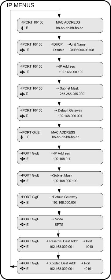
40 3 IP Menus Use the IP menus is to configure the 10/100 port. MAC Address Menu Use the following procedure to view the MAC address for the lower Ethernet port on the back panel of the DSR Press the 56 buttons until the MAC Address menu appears. This menu displays the Ethernet port MAC address. The address is represented in a hexadecimal format and it is not editable. DHCP Menu Press the 56 buttons until the Port 10/100 DHCP menu appears. The front panel screen displays the DHCP and Unit Name fields. DHCP (Dynamic Host Configuration Protocol) allows the Satellite Multiplex Decrypter to obtain a set of IP parameters from a DHCP server. The DHCP server ensures that all these IP addresses are unique. This automates and facilitates the Satellite Multiplex Decrypter's access to the network. The management of the IP address pool, in this case, is handled by the server, and not by a human administrator. DHCP Field Enter the field and choose either Enable or Disable. Unit Name Field The Unit Name is fully editable. It is placed into the outgoing DHCP request and is used for registration. The Unit Name, in most cases, is only a suggestion to the DHCP server and may be updated with a different name upon receiving the DHCP registration reply. If an updated name is received from a DHCP server, the Unit Name will be adjusted to show this change and will replace the user-entered name. The default name is DSR
41 Operating the DSR-6050 IP Address Menu Use the following procedure to set and view the IP address for the lower Ethernet port on the back panel of the DSR Press the 56 buttons until the IP Address menu appears. This menu allows the user to enter an IP address for the Ethernet port. The address is represented in the common dotted-decimal format. Contact the network administrator for details about configuring the Ethernet port for operation on your local network. Press the4button until the cursor is at the Address label, and press the ENTER button to move into the field. Press the34and 56buttons to enter the desired address and then press ENTER to confirm the selection. Subnet Mask Menu Use the following procedure to set and view the Subnet Mask address for the lower Ethernet port on the back panel of the DSR Press the 56 buttons until the Subnet Mask menu appears. This menu allows the user to enter a subnet mask for the Ethernet port. The subnet mask is represented in the common dotted-decimal format. Contact the network administrator for details about configuring the Ethernet port for operation on your local network. Press the4button until the cursor is at the Address label, and press the ENTER button to move into the field. Use the arrow button (3456) to enter the desired address and then press the ENTER button to confirm the selection. DSR
42 3 IP Gateway Menu Use the following procedure to set and view the Default Gateway address for the lower Ethernet port on the back panel of the DSR Press the 56 buttons until the IP Gateway menu appears. This menu allows the user to enter an IP gateway address that the Ethernet port should use. The IP Gateway is an address that is represented in the common dotted-decimal format. Contact the network administrator for details about configuring the Ethernet port for operation on your local network. Press the4button until the cursor is at the Default Gateway address, and press the ENTER button to move into the field. Use the arrow buttons (3456) to enter the desired address and then press the ENTER button to confirm the selection. Port GigE MAC Address Menu Use the following procedure to view the GigE MAC address for the upper Ethernet port on the back panel of the DSR Press the 56 buttons until the Port GigE menu appears. The address is represented in a hexadecimal format and it is not editable. 36
43 Operating the DSR-6050 GigE IP Address Menu Use the following procedure to set and view the GigE IP address for the upper Ethernet port on the back panel of the DSR Press the 56 buttons until the GigE IP Address menu appears. This menu allows the user to enter an IP address for the GigE port. The address is represented in the common dotted-decimal format. Contact the network administrator for details about configuring the GigE port for operation on your local network. Press the4button until the cursor is at the IP Address field, and press the ENTER button to move into the field. Press the34and 56buttons to enter the desired address and then press ENTER to confirm the selection. GigE Subnet Mask Menu Use the following procedure to set and view the GigE Subnet Mask for the upper Ethernet port on the back panel of the DSR Press the 56 buttons until the GigE Subnet Mask menu appears. The GigE subnet mask is represented in the common dotted-decimal format. Contact the network administrator for details about configuring the GigE port for operation on your local network. Press the4button until the cursor is at the Subnet Mask label, and press the ENTER button to move into the field. Use the arrow button (3456) to enter the desired address and then press the ENTER button to confirm the selection. DSR
44 3 GigE Default Gateway Menu Use the following procedure to set and view the GigE Default Gateway address for the upper Ethernet port on the back panel of the DSR Press the 56 buttons until the GigE Default Gateway Address menu appears. This menu allows the user to enter the GigE Default gateway address that the Ethernet port should use. The GigE Default Gateway is an address that is represented in the common dotteddecimal format. Contact the network administrator for details about configuring the GigE port for operation on your local network. Press the4button until the cursor is at the Default Gateway label, and press the ENTER button to move into the field. Use the arrow buttons (3456) to enter the desired address and then press the ENTER button to confirm the selection. GigE Mode Menu Press the 56 buttons until the GigE SPTS Mode menu appears. This menu allows the user to select which single program transport streams (SPTS) are routed to the GigE port. The DSR-6050 builds a transport stream that contains the userselected service. The compression format of the video and audio components in this service can be changed per instructions received from the programmer when the user selects the Transcoded option. The compression formats of this service is unchanged when the user selects the Passthru option. The DSR-6050 also allows the user to select both options, in which case two transport streams are routed to the GigE port. Both transport streams contain the same service, but the video and audio compression format has been changed for one transport stream. Press the 4 button until the cursor is at the SPTS Mode label, and press the ENTER button to move into the field. Press the 56 buttons to display the four options: Transcoded, Off, Passthru, and Passthru plus Transcoded. Press ENTER to confirm the selection. 38
45 Operating the DSR-6050 GigE Passthru Dest Addr Menu Use the following procedure to set and view the passthrough SPTS destination address. The passthrough single program transport stream is described in the section entitled "GigE Mode Menu." Press the56buttons until the GigE Passthru Dest Addr menu appears. The pass-through SPTS destination address is represented in the common dotted-decimal format. Contact the network administrator for details about configuring the pass-through SPTS destination address on your local network. Passthru Dest Addr Field Port Field Press the4button until the cursor is at the Passthru Dest Addr label, and press the ENTER button to move into the field. Use the arrow button (3456) to enter the desired address and then press the ENTER button to confirm the selection. Press the4 button until the cursor is at the Port label, and press the ENTER button to move into the field. Use the arrow button (3456) to enter the desired port ID (Range: to 65535) and then press the ENTER button to confirm the selection. The default is GigE Xcoded Dest Addr Menu Use the following procedure to set and view the transcoded SPTS destination address. The transcoded single program transport stream is described in the section entitled "GigE Mode Menu." Press the56buttons until the GigE Xcoded Dest Addr menu appears. The transcoded SPTS destination address is represented in the common dotted-decimal format. Contact the network administrator for details about configuring the transcoded SPTS destination address on your local network. DSR
46 3 Xcoded Dest Addr Field Press the4button until the cursor is at the Xcoded Dest Addr label, and press the ENTER button to move into the field. Use the arrow button (3456) to enter the desired address and then press the ENTER button to confirm the selection. Port Field Press the4button until the cursor is at the Port label, and press the ENTER button to move into the field. Use the arrow button (3456) to enter the desired port ID (Range: to 65535) and then press the ENTER button to confirm the selection. The default is
47 Operating the DSR-6050 Status Display Menus Status display menus provide information regarding the current status of the DSR This menu lists important Satellite Multiplex Decrypter parameters. These fields are not editable, and the displayed information is either (1) the result of changes in an installation or channel selection menu, or (2) a parameter the DSR-6050 reports as part of its operation. Status1 Menu Press the56buttons until the Status1 menu appears. Front Panel Field The Front Panel field indicates whether the user is able to control the Satellite Multiplex Decrypter completely from the front panel or whether some front panel functions are disabled. Input Type Field The Input Type field indicates the input connector on which the active signal is received. Status2 Menu This menu does not appear if the Input field (described on page 13) is set to ASI In. Press the56buttons until the STATUS2 menu appears. This screen displays the source name, channel number, and the signal quality. Source Field The Source field displays the source name, which was entered by the programmer or network operator at the encoder/uplink to identify the source. Dashes are displayed when no information is available. DSR
48 3 Channel Field Quality Field The Channel field displays the selected virtual channel number (from the Channel menu). Dashes are displayed when no information is available. The Quality field displays a number from 1 to 100 so that the quality level of the signal can be judged. The signal quality is also displayed as a large bar graph in the Status3 menu. If the signal is 50 or less, it is marginal. If it is 35 or less, take action at your site to increase the dish size or improve the LNB to prevent occasional loss of output. Status3 Menu This menu does not appear if the Input field (described on page 13) is set to ASI In. Press the56buttons until the STATUS3 menu appears. This screen displays the quality level of the signal as a large bar graph that expands to fill the entire LCD screen. Status4 Menu This menu does not appear if the Input field (described on page 13) is set to ASI In. Press the56buttons until the STATUS4 menu appears. This screen displays the satellite name and signal tuning characteristics. Sat Field Freq Field This field displays the satellite name from the downloaded network information. Dashes are displayed when no information is available. This field displays the downlink frequency of the L-band signal. This may be different from the frequency that was initially set in the Manual Tune menu. 42
49 Operating the DSR-6050 Symb Field Code Field Format Field This field displays the symbol rate (megasymbols per second) of the L-band signal. Dashes indicate that no information is available or when the ASI input is in use. This field displays the code rate (error control coding for forward error correction) of the L-band signal. This field displays the format (combined or split) of the L-band signal. Dashes are displayed when no information is available or when the ASI input is in use. Status5 Menu This menu does not appear if the Input field (described on page 13) is set to ASI In. Press the56buttons until the STATUS5 menu appears. This screen displays the sync, Eb/No and authorization state of the DSR Sync Field Eb/No Field This field displays the acquisition Sync state. The Sync state can be either Locked or Tuning. This field displays the Eb/No. Eb/No is a measure of signal to noise. Authorization State Field This field displays the authorization state of the current selected channel. Authorization State indicates how the Satellite Multiplex Decrypter is authorized. If the Authorization State is Not Authorized, the field will alternate, and display a reason why it is not authorized (e.g., Not in Sync). DSR
50 3 Status6 Menu Press the56buttons until the STATUS6 menu appears. This screen displays the DSR-6050 s Memory (free memory), and Flash. Memory Field Flash Field This status-only field displays the amount of free volatile memory in MB units that is available for use by the operating system. This status-only field displays the amount of free non-volatile memory in MB units that is available for use by the operating system. Status7 Menu Press the56buttons until the Status7 menu appears. This screen displays the video encoding configuration for the transcoded SPTS. The transcoded single program transport stream is described in the section entitled GigE Mode Menu. Video Resolution Field The Video Resolution field indicates the display resolution and scanning method of the transcoded video. this is represented as the numberof distinct pixels in thehorizontal dimension, the number of lines, and whetherthescan is progressive (p) or interlaced (i). Bit Rate Field The Bit Rate field indicates the data rate of the transcoded video. 44
51 Operating the DSR-6050 Status8 Menu Press56the buttons until the Status8 menu appears. This screen displays the audio encoding configuration for the transcoded SPTS. The transcoded single program transport stream is described in the sectin entitled GigE Mode Menu. Audio Field Use this field to choose which audio channel to display the status. Press the4button until the cursor is at the Audio field, then use the56buttons to choose the first audio channel or the second audio channel. The default is 1. Press the ENTER button to confirm the selection and exit the field. Format Field The Format field indicates the compression format of the transcoded audio for the selected audio channel. Mode Field The Mode field indicates the mode (stereo or mono) of the transcoded audio for the selected audio channel. Bit Rate Field The Bit Rate Field indicates the data rate of the transcoded audio. DSR
52 3 Diagnostics Menus Use the DSR-6050's diagnostic menu to get additional information for troubleshooting. The menus also enable the user to test waveforms and use other diagnostic information displayed on an NTSC television monitor connected through the rear panel video output. Caution: Turning on diagnostics changes the video or audio output, and these diagnostic screens or tones may be transmitted to the cable customers if the transcoder is connected to the cable plant. Press the 56buttons until the DIAGNOSTICS menu appears. Menus Field The Menus field allows the user to enable or disable the on-screen diagnostics. Press the4button until the cursor is at the Menus label, and press the ENTER button to move into the field. Press the 56 buttons to scroll to the televised screen of choice. Press the ENTER button to exit this field. The default is Off. Notice that if the Menus field is ON, the Clear Cntrs (clear counters) field also appears. Clear Cntrs Field This field allows the user to reset selected counters to zero. This field is primarily for use with hotline troubleshooting, and it is recommended that it be used only when so directed and does not affect transcoder operation, but it may give misleading troubleshooting results. To clear counters, press the4button until the cursor is at the Cntrs label, and press the ENTER button to reset the counters to zero. Unit Address Menu This menu is for display only and displays the DSR-6050 s 16-digit electronic address (range: to ). The program provider uses this address to identify a specific DSR-6050 for authorization and to retune messages. The display enables the user to view the address from the front panel rather than reading the label on the back panel. 46
53 Operating the DSR-6050 Press the 56 buttons until the Unit Address menu appears. TV Pass Card Menu The DSR-6050 does not initially require a TV Pass Card, but if one is required, the program provider typically supplies one. The program provider uses the TV Pass Card address and decoder address to identify a specific DSR-6050 for authorization messages. Press the 56 buttons until the TV Pass Card menu appears. The display enables the user to view the TV Pass Card address from the front panel of the DSR There are three Status field options: Not Inserted xxx-xxxxx-xxxxx-xxx (a unique TV Pass Card address, range: to ) xxx-xxxxx-xxxxx-xxx Needs Mating. Audio Test Signal Menu DSR-6050 supports AC3 passthrough audio. Support for analog audio will be considered for a future release. Video Test Signal Menu Press the56buttons until the Video Test Signal menu appears. A full-field video test signal is available and the user can display different test patterns by selecting the Pattern field. DSR
54 3 Pattern Field Press the4button until the cursor is at the Pattern label, and press the ENTER button to move into the field. Press the56buttons to display the test patterns. Choose from the options listed below: NTSC/PAL M Test Pattern Options Color Bar IRE 100 Ramp NTSC 7 Comb Red Field NTSC 7 Comp 5 Step Stair Unmod Y Ramp Off (Default) Press the ENTER button and a warning message appears saying that the current video display will be interrupted if the action proceeds. CAUTION: This selection replaces video Press E to continue or to stop Press any arrow button (3456) to back out of the field and leave it unchanged. Otherwise, press the ENTER button to proceed. Test signals override any active service component, and the DSR-6050 displays diagnostics over the video test patterns if diagnostics are enabled. Disable the selected signals by displaying OFF or exiting the menu. Press the ENTER button to exit from the field. 48
55 Operating the DSR-6050 VITS Menu Press the56buttons until the Vertical Interval Test Signal (VITS) menu appears. This menu allows the user to insert VITS on lines 17 or 18. VITS Waveform E Transmitted Waveform Field Note: Upon exiting this submenu, the Waveform field will revert back to the default value (Transmitted). The Waveform field allows the user to insert a VITS from several internally stored patterns, from a pattern transmitted over the satellite link, or to turn off VITS insertion. Press the4button until the cursor is at the Waveform label, and press the ENTER button to move into the field. Press the56buttons to display the options. Choose from the options listed below: NTSC/PAL M VITS Pattern Field Options Transmitted (Default) Disabled Color Bar 100 IRE Ramp NTSC 7 Comb Red Field NTSC 7 Comp 5 Step Stair Unmod Y Ramp The Transmitted option (the default) indicates the signal is provided over the satellite link by the programmer, if one is present. Press the ENTER button to confirm the selection. DSR
56 3 Note: If the Waveform option is neither Transmitted or Disabled, the Field and Line fields are displayed on the VITS menu. VITS Waveform Field Line E Color Bar 1 17 Field Field Line Field This field allows the user to select the field on which the VITS is reinserted by the transcoder. There are two choices, Field 1 or Field 2. Press the4button until the cursor is at the Field label, and press the ENTER button to move into the field. Press the56buttons to select the desired option and press the ENTER button to confirm the selection. Press the4button until the cursor is at the Line label, and press the ENTER button to move into the field. Press the56buttons to display the options. The available line numbers are 17 or 18. The default is line 17. Press the ENTER button to confirm the selection. Ad Insertion Test Menu Ad insertion signals are generated by the DSR-6050, but controlled by the uplink programmer. Local cable companies use ad insertion signals to control and to queue the insertion of commercials in cable headends. There are two ways to provide ad insertion. One is a dedicated digital DTMF differential output for cue tones. The other ad is a dedicated contact closure relay. The Ad Insertion Test menu allows the user to turn cue tones and the relays on and off. AD INSERTION TEST Cue Tone Relay E Off Off Caution: Output to the customers may be interrupted. When turned on, the ad insertion signals can be sent to the local headed equipment. Press the56buttons until the Ad Insertion Test menu appears. Cue Tone Signal Field The Cue Tone Sig (Signal) field lets the user turn the cue tone test On and Off. Press the4button until the cursor is at the Cue Tone Sig label, and press the ENTER button to move into the field. Press the56buttons to display the options. If On is selected, the DSR-6050 generates a DTMF code (0-9*#ABCD) on the cue 50
57 Operating the DSR-6050 Relay Field tone output. This field returns to the default value (OFF) when the ENTER button is pressed to exit the field. The Relay field lets the user individually turn ON and OFF each of the three ad insertion relays. Press the ENTER button to move into the field. Press the56buttons to display the options. The available options are OFF, Relay 1 ON, Relay 2 ON, and Relay 3 ON. This field returns to the default value (OFF) when the ENTER button is pressed to exit the field. DSR
58 3 52
59 4 Troubleshooting Before contacting the Hotline, review Table 4-1 for problems and suggested solutions. Table 4-1: Troubleshooting Solutions Problem Possible Cause Solution Reference LCD blank, no LEDs lit. No power to unit. Plug in the unit LEDs illuminate, but LCD is blank or too dark to read. LCD contrast out of adjustment. Adjust LCD contrast See IRD menu, Contrast field No picture, no level indication. No LNB signal port. Connect LNB coax See "Connecting the DSR-6050" on page 3. Poor audio quality or low audio level. No video or Bypass Video is present. No audio or Bypass Audio is present. Audio levels incorrect. Unit is in bypass mode. Unit is in bypass mode. Adjust audio levels Change to an available channel. Change to an available channel. Will not acquire. Port not configured. Check port configuration and manual frequency tune Incorrect language. Wrong language setting. Check language screen settings DSR
60
61 5 Product Support If You Need Help For assistance with Motorola products only, contact the Motorola Technical Response Center (TRC), 24 hours a day, 7 days a week: Inside the U.S.: HELP ( ) Outside the U.S.: Motorola Online: This offers a searchable solutions database, technical documentation, and low-priority issue creation and tracking. Calling for Repairs If repair is necessary, call Motorola s authorized repair vendor, World Wide Digital (WWD) at or for a Return for Service Authorization (RSA) number before sending the unit for repair. The RSA number must be prominently displayed on all equipment cartons. WWD is open from 8:00 AM to 5:00 PM Central Time, Monday through Friday. When shipping equipment for repair, follow these steps: 1. Pack the unit securely. 2. Enclose a note describing the exact problem. 3. Enclose a copy of the invoice to verify the warranty status. 4. Label all cartons with the RSA number. 5. Ship the unit PREPAID to: World Wide Digital c/o Loera Customs Brokerage, Inc. Attn: RSA # **** 5845 E. 14th Street, Suite D Brownsville, TX DSR
62
63 6 Downlink/L-Band Frequency Conversion Tables A distributor or programmer can provide the latest C-band and Ku-band frequency plans at purchase time. If desired, the following formulas have been provided to perform calculations for both C-band and Ku-band transponders, or if the user is installing for a new satellite. Table 6-1: Calculation for C-Band Transponders Formula for C-band Frequency Example calculation if downlink frequency is 3,740 MHz 5,150 MHz <minus> Frequency Downlink (DL) <equals> Frequency (C-band) 5,150 MHz -3,740 MHz 1,410 MHz Table 6-2: Calculation for Ku-Band Transponders Formula for Ku-band Frequency Frequency Downlink (DL) <minus> 10,750 MHz <equals> Frequency (Ku-band) Example calculation if downlink frequency is 12,019 MHz 12,019 MHz -10,750 MHz 1,269 MHz DSR
64
65 7 Language Abbreviations Note: This list of languages was recommended to system operators as the appropriate identifiers for audio, subtitle, and text information. Refer to Language Menu operation. LANGUAGE ABBREVIATION LANGUAGE ABBREVIATION Arabic ara Egyptian egy Armenian arm English eng Balinese ban Esperanto epo Basque baq Faroese fao Batak btk Finnish fin Bengali ben French fre Bhojpuri bho German ger Bulgarian bul Greek gre Burmese bur Gujarati guj Catalan cat Hebrew heb Chinese chi Hindi hin Croatian scr Hiri Motu hmo Cue (Tones) cue Hungarian hun Czech cze Indonesian ind Danish dan Interlingua ina Dutch dut Iranian ira DSR
66 7 LANGUAGE ABBREVIATION LANGUAGE ABBREVIATION Irish iri Philippine (Other) phi Italian ita Polish pol Panjabi pan Portuguese por Japanese jpn Rajasthani raj Javanese jav Romanian rum Kashmiri kas Russian rus Korean kor Samoan smo Kurdish kur Scots sco Latin lat Sindhi snd Malay may Spanish spa Mandar mdr Swahili swa Marathi mar Swedish swe Miscellaneous mis Tagalog tgl Mongolian mon Tamil tam Nepali nep Thai tha Norwegian nor Urdu urd Otomian Lang. oto Vietnamese vie Pahlavi pal Welsh wel Persian per 60
67 8 Diagnostics Introduction The Fast Fact Diagnostic Diagnostic screens (1 through 5) are a part of the Transcoder Firmware created during product development and based on the needs of the the particular unit. All values and information shown on the Fast Fact Diagnostic screens update when displayed, unless otherwise noted. Information about these screens is described here for documentation purposes only. Notes: 1. Hexadecimal numbers are displayed with none or more leading zeros (0) to pad to their individual field width. 2. Decimal numbers are right-justified in their individual display rectangle and are not padded with leading zeros (0). 3. Decimal numbers may be displayed without or with a trailing decimal point to distinguish them from hexadecimal numbers. 4. The default is no trailing decimal point. DSR
68 8 Viewing the Fast Fact Diagnostic Screens The diagnostic screens (Figure 8-1 on page 62) are available via the On-Screen Display (OSD) video out using a video monitor connected to the OSD Video Out on the rear of the transcoder. To view the OSD diagnostic screens, press the 56buttons on the front of the transcoder until the Diagnostic menu appears, and press the ENTER button to access the Diagnostic menu on the transcoder. Press the 56buttons, navigate to the DIAGNOSTIC Menus option and press the right arrow key. Selecting ENTER while the cursor is on the Menus option allows access to the OSD diagnostic screens. Use the 56buttons on the front of the transcoder to navigate between the Fast Fact Diagnostic screens while displaying the data to the OSD. Note: Pressing the ENTER button on the front of the transcoder while viewing a particular OSD diagnostic screen allows for the continued display of the OSD diagnostic information while allowing the user to navigates thru other front panel menus. FF1 Fast Facts 1 [page 64] FF2 Fast Facts 2 [page 66] FF3 Fast Facts 3 (Video) [page 67] FF4 Fast Facts 4 (Audio) [page 69] FF5 Fast Facts 5 (10/100 Network) [page 70] FF5 Fast Facts 5 GigE Network [page 71] Figure 8-1: Fast Fact Diagnostic Screens 62
69 Diagnostics Fast Facts Screens The Fast Facts screens are used as a method of viewing information and diagnostic data associated with the transcoder than what is shown in the transcoder s Diagnostic menu screens (refer to Diagnostic Menus). The Fast Facts screens are composed of five screens; the first screen showing important general information as it relates to the transcoder, the second screen depicts the current port configuration, the third screen shows important video information, the fourth screen displays important audio information, and the fifth screens shows the Ethernet configuration. DSR
70 8 Fast Facts 1 The Fast Facts 1 screen displays general information relating to the basic functionality of the transcoder. Fast Facts 1 Unit = A Firmware = C C Encryption = N/A E Auth State = N/A G Signal State = Searching I Signal Quality = 58 K Symbol Rate = Msps M Frequency = MHz O VC # = 0132 B VCTID = 0002 D Service # = F Eb/No = -2.0 H Sat/Xpndr = T6/7 J Polarization = Horz L FEC Rate = 3/4 N Virtual Network = 7 P Field Name Definition A B C D E F G H I Unit VC# Firmware VCT ID Encryption Service Auth State Eb/No Signal State Displays the 16-digit Unit Address on the screen. Shows the virtual channel number. Shows the firmware version in the boot sector of ROM and the application section. Shows the current VCT ID. TBD Displays the service number for the current program. Current authorization state, such as encrypted, fixed key, etc. Shows the Signal to Noise (Eb/No) of the signal. Shows the received signal state. It can either be "Locked" or "Searching" depending on whether the IRD is locked to a signal or not. 64
71 Diagnostics Field Name Definition J K L M N O P Sat/Xpndr Signal Strength/ Signal Quality Polarization Symbol Rate FEC Rate Frequency Virtual Network Displays the satellite name and transponder number. If the satellite name is null, then the satellite number is used. Puts up the Signal Quality if DCII; else, puts up the Signal Strength. Both values are normalized to be between 0 and 100%. Shows the polarization for the currently tuned-to transponder, either: Horz = Horizontal Vert = Vertical Shows the current symbol rate. Displays the Forward Error correction (FEC) coding rate. Shows the current RF frequency. Current virtual network that the DSR6050 is tuned to. DSR
72 8 Fast Facts 2 The Fast Facts 2 screen displays information relating to the port configuration of the transcoder. Fast Facts 2 Port 0 + S1: Horz... Defined Port 1 + T6: Vert... Defined A B C D E Field Name Definition A Port number The port number being described (0-7). B C D E Active Status Satellite Name Polarization Configuration Status +: indicates the port is Active. =: indicates the port is Inactive. The name of the current satellite. The polarity transponder associated with the port, either: Horz : Horizontal Vert : Vertical The configuration status of the port, either: Defined, Undefined or Not Supported. 66
73 Diagnostics Fast Facts 3 The Fast Facts 3 screen displays information relating to video information. A B C D E F G H I J K L M N O P Field Name Definition A B C D E F G H I Video Locked Monitor Video PID Window Dimensions PCR Pid Aspect Mode Source Format Video Setup Resolution An indication of video lock status, if yes then the video for the transcoder is being received and locked. If No, then the video is not being received. The current output format of the video display. The current Program Identification (PID) number for the Video. The current dimensions of the video display: Width x Height, Xpos : Ypos (or mute) The current Program Clock Reference (PCR) PID. The current aspect mode for the incoming video. The source format: Interlaced or Progressive. Indication if the video setup (pedestal) is active. Displays the Horizontal Size X Vertical Size of the received video. DSR
74 8 Field Name Definition J K L M N O P Film Mode Aspect Ratio Video Mute Count (VMC) Frame Rate PTS : FIFO Chroma Ratio Video Rate Indication of if Film Mode is active or inactive. The aspect ratio of the video within the transport stream. The current video mute count. The frame rate code of the stream. The video Presentation Time Stamp (PTS) followed by the Picture FIFO Depth Count. The Chrominance format for the video within the transport stream. The rate (in Mbps) of the video within the transport stream. 68
75 Diagnostics Fast Facts 4 The Fast Facts 4 screen displays information relating to audio information. There are two columns of information displayed, one column for the first audio program, and the other column for the second audio program. A A B B C C D D E E F F G G H H Field Name Definition A B C D E F G H Audio Locked Audio Pid PCR Pid Type Sample Rate Audio Mix Language Preference Language Status An indication of audio lock status for both audio programs. If yes, then the audio for the transcoder is being received and locked. If No, then the audio is not being received. The current Audio PID for both audio programs. The current PCR PID for both audio programs. The audio stream type: MPEG, AAC, AC3, etc. The sampling rate (in khz) of both audio programs. The audio processing mode for both audio programs: Mono, Stereo, Surround, etc. The preferred language setting for both audio programs. The language status for both audio programs. DSR
76 8 Fast Facts 5 (10/100 Network) The Fast Facts 5 screen displays information relating to the Ethernet port (upper RJ45 port on rear of transcoder) configuration. Port 10/100 Fast Facts 5 (10/100 Network) IP Address = A Subnet Mask = B Gateway = C MAC Address = 00:09:0E:CC:70:55 D Field Name Definition A B C D IP Address Subnet Mask Gateway MAC Address Gives the current IP address of the unit. The current subnet mask of the unit. The current gateway of the unit. The MAC address of the unit. 70
77 Diagnostics Fast Facts 5 (Gigabit Ethernet) The Fast Facts 5 (Gigabit Ethernet) screen displays information relating to Gigabit Ethernet port (lower RJ45 port on rear of transcoder) configuration. Port GigE A B C D E Fast Facts 5 (GigE Network) IP Address = Subnet Mask = Gateway = MAC Address = 00:09:0E:CC:70:55 Dest IP Addr = Dest Port = Output Mode = MPTS G F Field Name Definition A B C D E F G H IP Address Subnet Mask Gateway MAC Address Gateway Dest IP Address Dest Port Output Mode IP address of the GiGE ethernet. Subnet mask of the GiGE ethernet. Gateway of the GiGE ethernet. MAC Address of the GiGE ethernet. Gateway of the GiGE ethernet. Destination IP address. Destination port. Displays the output mode for the GiGE ethernet port. DSR
78
79 9 DSR-6050 Specifications RF Input Frequency Range Input RF Level RF Port Impedance RF Port Return Loss Port-to-Port Isolation 950 to 2150 MHz -25 to -65 dbm 75 Ohms 13 db minimum 40 db minimum Video Frequency response ±0.9 db (1 khz to 4.2 MHz) NTSC ±0.9 db (1 khz to 4.8 MHz) PAL +0/1.5 db (4.8 MHz to 5.5 MHz) PAL Video Level 1.0V p-p ± 10% Chrominance-luminance Delay Inequality Differential Gain Differential Phase ±40 nsec 4.5% p-p maximum (10% to 90% APL) 4.5% p-p maximum (10% to 90% APL) DSR
80 9 Transmission Standard DigiCipher II Symbol Rates 3.25, 4.88, 7.32, 9.76, 11.71, 14.63, 19.51, and Msps discrete steps DigiCipher II Code Rates 5/11, 1/2, 3/5, 2/3, 3/4, 4/5, 5/6, 7/8 8PSK-TurboCode FEC Rates 2/3(1.92), 3/4(2.05), 3/4(2.11), 3/4(2.19), 5/6(2.30), 8/9(2.40) DVB-S2 FEC Rates 3/5, 2/3, 3/4, 5/6, 8/9, 9/10 Electrical Power Requirements LNB Power Supply 90 to 250 VAC, 47/63 Hz, 70 W V minimum, 480 ma loaded 74
81 DSR-6050 Specifications Connectors RF In F-type (Qty 8) Video Out BNC (Qty 1) OSD Video Out BNC (Qty 1) Alarm Screw terminal (Qty 1) Cue Tone (Labeled: Q+ and Q-) Screw terminal (Qty 1) Audio In Screw terminal (Qty 1) Audio Out Screw terminal (Qty 2) ISOC Data Screw terminal (Qty 1) ASYNC (not implemented) Contact Closure (Labeled: Relay 1, 2, and 3) Screw terminal (Qty 3) ASI In BNC connector (Qty 1) ASI Out BNC connector (Qty 2) Mechanical Dimensions H 3.1" (4.4 cm) W 19.0" (48.3 cm) D 20.50" (52 cm) Weight DSR
82
83 Caring for the Environment by Recycling When you see this symbol on a Motorola product, do not dispose of the product with residential or commercial waste. Beskyttelse af miljøet med genbrug Når du ser dette symbol på et Motorola-produkt, må produktet ikke bortskaffes sammen med husholdningsaffald eller erhvervsaffald. Umweltschutz durch Recycling Wenn Sie dieses Zeichen auf einem Produkt von Motorola sehen, entsorgen Sie das Produkt bitte nicht als gewöhnlichen Haus- oder Büromüll. Cuidar el medio ambiente mediante el reciclaje Cuando vea este símbolo en un producto Motorola, no lo deseche junto con residuos residenciales o comerciales. Recyclage pour le respect de l'environnement Lorsque vous voyez ce symbole sur un produit Motorola, ne le jetez pas avec vos ordures ménagères ou vos rebuts d'entreprise. Milieubewust recycleren Als u dit symbool op een Motorola-product ziet, gooi het dan niet bij het huishoudelijk afval of het bedrijfsafval. Dba o o rodowisko - recykling Produktów Motorola oznaczonych tym symbolem nie nale y wyrzuca do komunalnych pojemników na mieci. Cuidando do meio ambiente através da reciclagem Quando você ver este símbolo em um produto Motorola, não descarte o produto junto com lixo residencial ou comercial. Recycling your Motorola Equipment Please do not dispose of this product with your residential or commercial waste. Some countries or regions, such as the European Union, have set up systems to collect and recycle electrical and electronic waste items. Contact your local authorities for information about practices established for your region. If collection systems are not available, call Motorola Customer Service for assistance. Genbrug af dit Motorola-udstyr Dette produkt må ikke bortskaffes sammen med husholdningsaffald eller erhvervsaffald. Nogle lande eller områder, f.eks. EU, har oprettet systemer til indsamling og genbrug af elektriske og elektroniske affaldsprodukter. Kontakt de lokale myndigheder for oplysninger om gældende fremgangsmåder i dit område. Hvis der ikke findes tilgængelige indsamlingssystemer, kan du kontakte Motorola Kundeservice. Recycling bei Geräten von Motorola Bitte entsorgen Sie dieses Produkt nicht als gewöhnlichen Haus- oder Büromüll. In einigen Ländern und Gebieten, z. B. in der Europäischen Union, wurden Systeme für die Rücknahme und Wiederverwertung von Elektroschrott eingeführt. Erkundigen Sie sich bitte bei Ihrer Stadt- oder Kreisverwaltung nach der geltenden Entsorgungspraxis. Falls bei Ihnen noch kein Abfuhr- oder Rücknahmesystem besteht, wenden Sie sich bitte an den Kundendienst von Motorola. Reciclaje de su equipo Motorola No deseche este producto junto con sus residuos residenciales o comerciales. Algunos países o regiones, tales como la Unión Europea, han organizado sistemas para recoger y reciclar desechos eléctricos y electrónicos. Comuníquese con las autoridades locales para obtener información acerca de las prácticas vigentes en su región. Si no existen sistemas de recolección disponibles, solicite asistencia llamando el Servicio al Cliente de Motorola. Recyclage de votre équipement Motorola Veuillez ne pas jeter ce produit avec vos ordures ménagères ou vos rebuts d'entreprise. Certains pays ou certaines régions comme l'union Européenne ont mis en place des systèmes de collecte et de recyclage des produits électriques et électroniques mis au rebut. Veuillez contacter vos autorités locales pour vous informer des pratiques instaurées dans votre region. Si aucun système de collecte n'est disponible, veuillez appeler le Service clientèle de Motorola qui vous apportera son assistance. Uw Motorola-materiaal recycleren. Gooi dit product niet bij het huishoudelijk afval het of bedrijfsafval. In sommige landen of regio's zoals de Europese Unie, zijn er bepaalde systemen om elektrische of elektronische afvalproducten in te zamelen en te recycleren. Neem contact op met de plaatselijke overheid voor informatie over de geldende regels in uw regio. Indien er geen systemen bestaan, neemt u contact op met de klantendienst van Motorola. Recykling posiadanego sprz tu Motorola Produktu nie nale y wyrzuca do komunalnych pojemników na mieci. W niektórych krajach i regionach, np. w Unii Europejskiej, istniej systemy zbierania i recyklingu sprz tu elektrycznego i elektronicznego. Informacje o utylizacji tego rodzaju odpadów nale y uzyska od w adz lokalnych. Je li w danym regionie nie istniej systemy zbierania odpadów elektrycznych i elektronicznych, informacje o utylizacji nale y uzyska od biura obs ugi klienta firmy Motorola (Motorola Customer Service). Reciclagem do seu equipamento Motorola Não descarte este produto junto com o lixo residencial ou comercial. Alguns países ou regiões, tais como a União Européia, criaram sistemas para colecionar e reciclar produtos eletroeletrônicos. Para obter informações sobre as práticas estabelecidas para sua região, entre em contato com as autoridades locais. Se não houver sistemas de coleta disponíveis, entre em contato com o Serviço ao Cliente da Motorola para obter assistência.
84
85

86 RECYCLABLE (PAPER) 6450 Sequence Dr. San Diego, CA Document No: , Rev. A
Motorola DSR-6000 Commercial Integrated Receiver/Decoder Operator Guide
 Motorola DSR-6000 Commercial Integrated Receiver/Decoder Operator Guide STATUS Document No.: 557526-001 WARNING The unauthorized modification of any decoder and the sale and use of any such decoder is
CAUTION RISK OF ELECTRIC SHOCK NO NOT OPEN
 Evolution Digital HD Set-Top Box Important Safety Instructions 1. Read these instructions. 2. Keep these instructions. 3. Heed all warnings. 4. Follow all instructions. 5. Do not use this apparatus near
HD Digital Set-Top Box Quick Start Guide
 HD Digital Set-Top Box Quick Start Guide Eagle Communications HD Digital Set-Top Box Important Safety Instructions WARNING TO REDUCE THE RISK OF FIRE OR ELECTRIC SHOCK, DO NOT EXPOSE THIS PRODUCT TO RAIN
Evolution Digital HD Set-Top Box Important Safety Instructions
 Evolution Digital HD Set-Top Box Important Safety Instructions 1. Read these instructions. 2. Keep these instructions. 3. Heed all warnings. 4. Follow all instructions. 5. Do not use this apparatus near
HD Digital MPEG2 Encoder / QAM Modulator
 HD Digital MPEG2 Encoder / QAM Modulator HDMI In QAM Out series Get Going Guide ZvPro 800 Series is a one or two-channel unencrypted HDMI-to-QAM MPEG 2 Encoder / QAM Modulator, all in a compact package
Cisco D9859 Advanced Receiver Transcoder
 Deliver MPEG-4 high-definition (HD) services to MPEG-2 cable TV (CATV) headends with the Cisco D9859 Advanced Receiver Transcoder. The Cisco D9859 platform (Figures 1 and 2) extends the distribution options
DSR-4520X IRD Set-Up and Configuration Guidelines for Direct Reception on Galaxy 13
 DSR-4520X IRD Set-Up and Configuration Guidelines for Direct Reception on Galaxy 13 Version 1.9, 09/12/06 This document is intended as a supplement to and not as a substitute for the Operator Guide provided
DSR-7400 Series. Commercial Integrated Satellite Receiver/Transcoder. Highlights. Product Overview
 DSR-7400 Series Commercial Integrated Satellite Receiver/Transcoder Highlights DSR-7412 provides 24 transcoded output services (12 HD and 12 down-converted SD) DSR-7401 transcodes and down-converts up
Cisco D9859 Advanced Receiver Transcoder
 Data Sheet Cisco D9859 Advanced Receiver Transcoder Deliver MPEG-4 high-definition (HD) services to MPEG-2 cable TV (CATV) headends with the Cisco D9859 Advanced Receiver Transcoder. The Cisco D9859 platform
Z-IP Stream 004/008. User Guide and Installation Manual. Four or Eight Input QAM Encoder / Modulator
 Z-IP Stream 004/008 User Guide and Installation Manual Four or Eight Input QAM Encoder / Modulator MPEG-2 / H.264 HD ENCODER with QAM /IP/ & ASI Outputs Contents Safety Precautions... 3 Package Contents...
HD Digital MPEG2 Encoder / QAM Modulator
 HD Digital MPEG2 Encoder / QAM Modulator YPrPb VGA In QAM Out series Get Going Guide ZvPro 600 Series is a one or two-channel Component or VGA-to-QAM MPEG 2 Encoder/ Modulator, all in a compact package
IRD Quick Install Guide
 IRD Quick Install Guide Instructions acquiring HBO/Cinemax Programming Motorola DSR-series Digicipher II Commercial Receiver/Decoders* Installation of the Digicipher II IRD involves a simple hook up and
OWNER'S MANUAL MODEL: DTV-2000 STANDBY/ON
 OWNER'S MANUAL MODEL: DTV-2000 STANDBY/ON CH+ CH- TABLE OF CONTENTS SAFETY PRECAUTIONS IMPORTANT SAFETY INSTRUCTIONS and FEATURES ACCESSORIES and LOADING BATTERIES REMOTE CONTROL UNIT FRONT PANEL and REAR
HD Digital MPEG2 Encoder / QAM Modulator Get Going Guide
 series HD Digital MPEG2 Encoder / QAM Modulator Get Going Guide HDb2640 HDb2620 HDb2540 HDb2520 The HDbridge 2000 Series is a combination HD MPEG 2 Encoder and frequency-agile QAM Modulator, all in a 1RU
Be sure to run the vehicle engine while using this unit to avoid battery exhaustion.
 CAUTION: TO REDUCE THE RISK OF ELECTRIC SHOCK DO NOT REMOVE COVER (OR BACK) NO USER-SERVICEABLE PARTS INSIDE REFER SERVICING TO QUALIFIED SERVICE PERSONNE; Please Read all of these instructions regarding
Model 1421 Distribution Amplifier
 Model 1421 Distribution Amplifier Installation and Operating Instructions The 1421 Distribution Amplifier provides four independent, wide bandwidth outputs from one video input. The unit is color compatible
7881IRDA Series QUICK START GUIDE
 7881IRDA Series QUICK START GUIDE Copyright 2013-2015 EVERTZ MICROSYSTEMS LTD. 5292 John Lucas Drive, Burlington, Ontario, Canada L7L 5Z9 Phone: +1 905-335-3700 Sales: sales@evertz.com Fax: +1 905-335-3573
Installation Manual VIP 1003
 Installation Manual VIP 1003 We Caring for the Environment by Recycling When you see this symbol on a Motorola product, do not dispose of the product with residential or commercial waste. Recycling your
For flexible advertisement insertion configurations, this receiver provides four types of outputs:
 Product Overview The Cisco PowerVu Model D9850 Program Receiver (Figure 1) is designed for satellite content distribution applications requiring 4:2:0 video decoding. The receiver can receive digitally
Professional Media Server Quick Start Guide
 ipump 6400 Professional Media Server Quick Start Guide Figure 4. ipump Web Interface Status Page 6. Shut down your ipump from the front panel. Navigate from the home screen to the Shutdown screen as follows:
SignalOn Series. L-Band Splitter Module INSTALLATION & OPERATION MANUAL. 1.2 GHz. D3.
 SignalOn Series D3.1/CCAP Compliant 1.2 GHz L-Band Splitter Module INSTALLATION & OPERATION MANUAL www.atxnetworks.com www.atxnetworks.com Although every effort has been taken to ensure the accuracy of
17 19 PROFESSIONAL LCD COLOUR MONITOR ART
 17 19 PROFESSIONAL LCD COLOUR MONITOR ART. 41657-41659 Via Don Arrigoni, 5 24020 Rovetta S. Lorenzo (Bergamo) http://www.comelit.eu e-mail:export.department@comelit.it WARNING: TO REDUCE THE RISK OF FIRE
Refs , HDTV ENCODER/MODULATOR - Dual Component to QAM HDTV ENCODER/MODULATOR - Dual Component to QAM (EAS) QUICK INSTALLATION GUIDE
 QUICK INSTALLATION GUIDE") Refs. 563801, 563811 EN (EAS) QUICK INSTALLATION GUIDE w w w. t e l e v e s. c o m Safety instructions Caution statements Product inspection - Inspect the equipment for shipping damage. Should any damage
Refs. 563801, 563811 EN (EAS) QUICK INSTALLATION GUIDE w w w. t e l e v e s. c o m Safety instructions Caution statements Product inspection - Inspect the equipment for shipping damage. Should any damage
INSTALLATION MANUAL VIP 1903 / VIP 1903 T VIP 1963 / VIP 1963 T
 INSTALLATION MANUAL VIP 1903 / VIP 1903 T VIP 1963 / VIP 1963 T We Declaration of Conformity Motorola Mobility, Inc. 101 Tournament Drive Horsham Pennsylvania 19044 USA declare under our sole responsibility
HD-1600 Single Input MPEG-4 DVB-T HD Encoder/Modulator User Guide and Install Manual
 digi-mod HD Range digi-mod HD-1600 www.resi-linx.com HD-1600 Single Input MPEG-4 DVB-T HD Encoder/Modulator User Guide and Install Manual Table of Contents Safety Precautions 2 Package Contents 2 Product
USER MANUAL. 27 Full HD Widescreen LED Monitor L27ADS
 USER MANUAL 27 Full HD Widescreen LED Monitor L27ADS TABLE OF CONTENTS 1 Getting Started 2 Control Panel/ Back Panel 3 On Screen Display 4 Technical Specs 5 Care & Maintenance 6 Troubleshooting 7 Safety
HD-1603 Single Input MPEG-4 DVB-T HD Encoder/Modulator User Guide and Install Manual
 ZyCastR digi-mod HD Range digi-mod HD-1603 www.digi-modbyzycast.com HD-1603 Single Input MPEG-4 DVB-T HD Encoder/Modulator User Guide and Install Manual Table of Contents www.digi-modbyzycast.com Safety
Model D9854 Advanced Program Receiver
 MPEG-2/AVC Receiver Model D9854 Advanced Program Receiver The Model D9854 Advanced Program Receiver is designed for satellite content distribution applications requiring DVB-S and DVB-S2 reception capabilities
SKYPLAY-MX Installation and Operation Guide
 SKYPLAY-MX Installation and Operation Guide Rev 130412 Important Safety Instructions Please completely read and verify you understand all instructions in this manual before operating this equipment. Keep
Introduction. Important Safety Instructions
 Introduction Congratulations on purchasing your Eviant Portable Digital TV. On June 12, 2009 the conversion to digital television broadcasting will be complete all throughout the United States and Puerto
DVISm. DVISm - Mini Digital Video Insertion System. Quick Start Guide. Patent Pending
 DVISm Patent Pending DVISm - Mini Digital Video Insertion System Quick Start Guide Although every effort has been taken to ensure the accuracy of this document it may be necessary, without notice, to make
Instruction Guide. The TV Jockey Computer Monitor TV Tuner with Remote COMP2VGATVGB. The Professionals Source For Hard-to-Find Computer Parts
 VIDEO ADAPTER The TV Jockey Computer Monitor TV Tuner with Remote COMP2VGATVGB Instruction Guide * Actual product may vary from photo The Professionals Source For Hard-to-Find Computer Parts FCC COMPLIANCE
Cisco D9824 Advanced Multi Decryption Receiver
 Data Sheet Cisco D9824 Advanced Multi Decryption Receiver Product Overview The Cisco D9824 Advanced Multi Decryption Receiver (Figure 1) is designed for satellite and terrestrial content distribution applications
User s Manual HDMI Modulator ATSC 8VSB/QAM 65/256. Model No : HDM100
 User s Manual HDMI Modulator ATSC 8VSB/QAM 65/256 Model No : HDM100 Contents 1. Safety Instructions & Precautions. 1 2. Operation Guide.. 2 2-1. Connection Diagram. 2 2-2. Front Panel.... 3 2-3. Rear Panel.....
MyM-3S Micro Master. Installation Guide. English. design for TV
 MyM-3S Micro Master Installation Guide design for TV 1 CONTENT 1. Introduction 2. Unpacking the unit 3. Connections and indications 4. IP settings 5. Menus and settings 5.1 Overview menu 5.2 Input settings
GENERAL INFORMATION INSTALLATION MENU INFORMATION. Main Features For your Safety Unpacking General Operation RCU Rear Panel.
 GENERAL INFORMATION 3 Main Features For your Safety Unpacking General Operation RCU Rear Panel 3 4 7 7 8 9 INSTALLATION 10 MENU INFORMATION Main Menu 1. Installation 1.1 Satellite list 1.2 Dish Setting
Operation and Installation Guide
 Operation and Installation Guide HDS2800 Series Encoder Modulator High Definition (HD) Digital COFDM MPEG2 and H.264 Modulator with IP Multicast. 19 Rack Mount Revision 4.0 Firmware version Released File
AVE HOME FAGOR CVBS TO DVB-T ENCODER MODULATOR. Fagor Electr6nica
 AVE HOME CVBS TO DVB-T ENCODER MODULATOR FAGOR Fagor Electr6nica TABLE OF CONTENTS 1. SPECIFICATIONS... 12 1.1 Product Overview... 12 1.2 Appearance and Description... 12 1.3 Diagram... 13 1.4 Characteristics...
MANUAL ENG DT-1600 ENGLISH. Also contains Menu options and data for built-in modulator Data for broadband amplifier QPSK
 ENG-1 030206 01261-3 ENGLISH Also contains Menu options and data for built-in modulator Data for broadband amplifier QPSK A versatile digital receiver with a guaranteed future has been developed to transmit
USER MANUAL. 22" Class Slim HD Widescreen Monitor L215DS
 USER MANUAL 22" Class Slim HD Widescreen Monitor L215DS TABLE OF CONTENTS 1 Getting Started Package Includes Installation 2 Control Panel / Back Panel Control Panel Back Panel 3 On Screen Display 4 Technical
Register your product and get support at SDV5122/27. EN User manual
 Register your product and get support at www.philips.com/welcome SDV5122/27 User manual Contents 1 Important 4 Safety 4 Notice for USA 5 Notice for Canada 5 Recycling 6 English 2 Your SDV5122 7 Overview
MediaKind RX
 MediaKind RX8330 The MediaKind RX8330 Distribution Receiver provides feature-rich multi-format standard definition decoding capability with high quality SDI output for video distribution applications.
LTC 113x & LTC123x FlexiDome Series Fixed Dome Cameras
 LTC 113x & LTC123x FlexiDome Series Fixed Dome Cameras Eng Installation Instructions F D E NL I IMPORTANT SAFEGUARDS 1. Read Instructions All the safety and operating instructions should be read before
Cisco D9854-I Advanced Program Receiver
 Data Sheet Cisco D9854-I Advanced Program Receiver Product Overview The Cisco D9854-I Advanced Program Receiver (Figure 1) is designed for satellite and terrestrial content distribution applications requiring
Quick Start Digital Satellite Receiver
 Quick Start Digital Satellite Receiver Support of SD (MPEG2), DVB-S system Standard resolution video output - SCART Compatible with Diseqc 1.0, 1.1, 1.2, and USALS Electronic Program Guide - EPG Multilingual
QRF5000 MDU ENCODER. Data Sheet
 Radiant Communications Corporation 5001 Hadley Road South Plainfield NJ 07080 Tel (908) 757-7444 Fax (908) 757-8666 WWW.RCCFIBER.COM QRF5000 MDU ENCODER Data Sheet Version 1.1 1 Caution Verify proper grounding
 Register your product and get support at www.philips.com/welcome SDV5222T/27 User manual Contents 1 Important 4 Safety 4 Notice for USA 4 Notice for Canada 5 Recycling 5 English 2 Your SDV5222T 6 Overview
Table of Contents. 1. Safety Use. 2. General Description. 3. Connection Diagram. 4. Operations and Management. 4.1 Display Status. 4.
 DTM-HD01 Thank you for buying this encoder modulator. Please read this manual carefully to install, use and maintain the encoder modulator in the best conditions of performance. Keep this manual for future
Installation & Operational Manual
 Radiant Communications Corporation 5001 Hadley Road South Plainfield NJ 07080 Tel (908) 757-7444 Fax (908) 757-8666 WWW.RCCFIBER.COM QRF5000M MDU ENCODER Installation & Operational Manual Rev.A2 1. Introduction
Commercial IRD Options for Shaw Conversion
 Commercial IRD Options for Shaw Conversion January 26, 2017 Commercial IRD Products DSR-7401 DSR-7403, 7406, 7409 and DSR-7412 12 channel MPEG-2/4 HD/SD to SD transcoder AVAILABLE: NOW 3, 6, 9 and 12 channel
MyM Pro T2 Installation guide
 MyM Pro T2 Installation guide CONTENT 1. Introduction 2. Unpacking the unit 3. Connections and indications 4. IP settings 5. Menus and settings web ui 5.1 Overview menu 5.2 Input settings 5.3 Output settings
UNFOLD THE BASE. Quick Start Guide CONTENTS INSTALLING LCD TV ON THE WALL
 Quick Start Guide English CONTENTS INSTALLING LCD TV ON THE WALL.. UNFOLD THE BASE............... TV CHANNEL INSTALLATION........ PRESENTATION OF THE LCD TV..... ACCESSORIES.................... BATTERY
USER MANUAL. 27 Full HD Widescreen LED Monitor L270E
 USER MANUAL 27 Full HD Widescreen LED Monitor L270E TABLE OF CONTENTS 1 Getting Started 2 Control Panel/ Back Panel 3 On Screen Display 4 Technical Specs 5 Care & Maintenance 6 Troubleshooting 7 Safety
MyM Pro 3S/6S Installation guide
 MyM Pro 3S/6S Installation guide CONTENT 1. Introduction 2. Unpacking the unit 3. Connections and indications 4. IP settings 5. Menus and settings web ui 5.1 Overview menu 5.2 Input settings 5.3 Output
Disclaimer. Trademarks. Copyright. Contact Us Control4 Corporation S. Election Road Salt Lake City, UT USA
 Disclaimer Trademarks Copyright Control4 makes no representations or warranties with respect to this publication, and specifically disclaims any express or implied warranties of merchantability or fitness
ipump 562 Digital Media Server Quick Start Guide
 ipump 562 Digital Media Server Quick Start Guide. General Information The WEGENER ipump 562 is a digital media server capable of decoding satellite signals or IP streams or playing stored content from
CDV07. Analog video distribution amplifier(s)
") CDV07 Analog video distribution amplifier(s) TECHNICAL MANUAL CDV07 Analog video distribution amplifier Lange Wagenstraat 55 NL-5126 BB Gilze The Netherlands Phone: +31 161 850 450 Fax: +31 161 850 499
CDV07 Analog video distribution amplifier(s) TECHNICAL MANUAL CDV07 Analog video distribution amplifier Lange Wagenstraat 55 NL-5126 BB Gilze The Netherlands Phone: +31 161 850 450 Fax: +31 161 850 499
Operation and Installation Guide
 Operation and Installation Guide HDS2800 Series Encoder Modulator High Definition (HD) Digital COFDM MPEG2 and H.264 Modulator with IP Multicast. 19 Rack Mount Wall Mount Revision 0.1 Firmware version
Model#: IN-MDRI3MF. Hardware User Manual. 3MP Indoor Mini Dome with Basic WDR, Fixed lens. (PoE) Ver. 2013/02/04
 Ver. 2013/02/04") Model#: IN-MDRI3MF 3MP Indoor Mini Dome with Basic WDR, Fixed lens Hardware User Manual (PoE) Ver. 2013/02/04 Table of Contents 0. Precautions 3 1. Introduction 4 Package Contents... 4 Features and Benefits...
Model#: IN-MDRI3MF 3MP Indoor Mini Dome with Basic WDR, Fixed lens Hardware User Manual (PoE) Ver. 2013/02/04 Table of Contents 0. Precautions 3 1. Introduction 4 Package Contents... 4 Features and Benefits...
Technical Manual August 2014
 Technical Manual Quick Reference... 3 Important Information... 4 Quick Set Up Guide... 5 Program and Data Delivery by Satellite... 6 IDC Receiver Installation Guide... 7 Introduction... 7 Antenna Requirements...
Shaw Conversion. March 18, 2016
 Commercial IRD Options for Shaw Conversion March 18, 2016 Commercial IRD Products DSR 7401 DSR 7403/7406/7409/7412 12 channel MPEG 2/4 HD/SD to SD transcoder AVAILABLE: SEP 2016 3, 6, 9 and 12 channel
MANUAL ENG DT-1610C. Also contains Menu options and data for built-in modulator Data for broadband amplifier QAM PAL
 ENG-1 050815 50026 Also contains Menu options and data for built-in modulator Data for broadband amplifier QAM PAL A versatile and future-proof digital receiver Built-in, thermostat controlled fan. Sound
M5-H002. Multiview T-35. DVB-T to PAL / 5 channels on all TV s
 120531 M5-H002 Multiview T-35 DVB-T to PAL / 5 channels on all TV s Contents Multiview... 3 Features... 3 Caution... 3 Front & Rear Panel... 4 Connecting... 5 Programming... 6 Information... 7 Installation...8
NMS ETA TM Stereo Advanced Digital TV Set-top Box
 Digital TV HD Set-top Box STB2-T2 NMS ETA TM Stereo Advanced Digital TV Set-top Box User Guide CONTENTS Safety Information... 3 Introduction... 4 Set-top Box Front Panel... 4 Set-top Box Back Panel...
WARNING/CAUTION FCC NOTICE
 WARNING/CAUTION The lightning flash with ar rowhead symbol, within an equilateral triangle, is intended to alert the user to the presence of uninsulated dangerous voltage within the product s enclosure
Cisco D9865 Satellite Receiver
 Cisco D9865 Satellite Receiver The Cisco D9865 Satellite Receiver is designed for satellite content distribution, and targets the broadcast, business TV, private networks, and SMATV environment. The receiver
USER MANUAL Full HD Widescreen LED Monitor L236VA
 USER MANUAL 23.6 Full HD Widescreen LED Monitor L236VA TABLE OF CONTENTS 1 Getting Started 2 Control Panel/ Back Panel 3 On Screen Display 4 Technical Specs 5 Care & Maintenance 6 Troubleshooting 7 Safety
AN2 Series. 900tvl. CMOS Technology High Resolution Sensor. elinetechnology.com P/N 01.BSM V1.0
 AN2 Series 900tvl CMOS Technology High Resolution Sensor P/N 01.BSM.16.2000030 V1.0 Product Made in China under ISO9001 & ISO1400 standards Manual Printed in China v1.0 elinetechnology.com CAUTION RISK
SYMBOLS USED ON THE RECEIVER... 3 SAFETY INSTRUCTIONS... 4 I.GENERAL INFORMATION...
 Table of Contents SYMBOLS USED ON THE RECEIVER... 3 SAFETY INSTRUCTIONS... 4 I.GENERAL INFORMATION... 5 1. Preface... 5 2. Main Features... 5 3. General Operation of the Receiver... 6 4. Front Panel...
 Register your product and get support at www.philips.com/welcome SWS3435S/27 SWS3435H/37 EN User manual Contents 1 Important 4 Safety 4 English 2 Your SWS3435 6 Overview 6 3 Installation 7 Connect the
MAX T200 HD QUICK INSTALLATION GUIDE
 MAX T200 HD QUICK INSTALLATION GUIDE MAX T200 HD QUICK INSTALLATION GUIDE CONTENT receiver BATTERIES x 2 REMOTE CONTROL Quick installation guide Quick Installation Guide The lightning flash with arrowhead
HDBaseT RECEIVER B-520-RX-230-IR INSTALLATION MANUAL
 HDBaseT RECEIVER B-520-RX-230-IR INSTALLATION MANUAL IMPORTANT SAFETY INSTRUCTIONS To reduce the risk of fire or electric shock, read and follow all instructions and warnings in this manual. Keep this
USER MANUAL Full HD Widescreen LED Monitor L215IPS
 USER MANUAL 21.5 Full HD Widescreen LED Monitor L215IPS TABLE OF CONTENTS 1 Getting Started 2 Control Panel/ Back Panel 3 On Screen Display 4 Technical Specs 5 Care & Maintenance 6 Troubleshooting 7 Safety
USER MANUAL. 28" 4K Ultra HD Monitor L28TN4K
 USER MANUAL 28" 4K Ultra HD Monitor L28TN4K TABLE OF CONTENTS 1 Getting Started 2 Control Panel/ Back Panel 3 On Screen Display 4 Technical Specs 5 Care & Maintenance 6 Troubleshooting 7 Safety Info &
Professional HD Integrated Receiver Decoder
 Professional HD Integrated Receiver Decoder User Manual V1.00-C Preface About This Manual This manual provides introductions to users about how to operate the device correctly. The content includes introduction
MANUAL ENG DT-1000CI ENGLISH QPSK
 ENG-3 010914 01034 ENGLISH QPSK A versatile digital receiver with a guaranteed future One of the advantages of is its flexible construction. The receiver is equipped with a Common Interface, which enables
Before you can install your LCD TV on the wall, you must fi rst remove the base using the steps below:
 Quick Start Guide English CONTENTS INSTALLING LCD TV ON THE WALL.. TV CHANNEL INSTALLATION........ PRESENTATION OF THE LCD TV...... ACCESSORIES.................... BATTERY INSTALLATION............ REMOTE
2.4 GHz WIRELESS VIDEO SENDER SYSTEM MODEL: VS6234
 2.4 GHz WIRELESS VIDEO SENDER SYSTEM MODEL: VS6234 Please read this manual thoroughly before operating this system OPERATING INSTRUCTIONS 03/02 1 SAFETY INSTRUCTIONS CAUTION! RISK OF ELECTRIC SHOCK. DO
Welcome to NEED HELP? DIRECTV offers the best entertainment experience. Use this guide to make the most of it LKR FCC ID : ORS
 NEED HELP? Important Tips Do not unplug your receiver If you unplug it you may miss the most recent updates that improve our service. The DIRECTV receiver is designed to consume very little energy while
HDBaseT RECEIVER B-540-RX-330-IR INSTALLATION MANUAL
 HDBaseT RECEIVER B-540-RX-330-IR INSTALLATION MANUAL IMPORTANT SAFETY INSTRUCTIONS To reduce the risk of fire or electric shock, read and follow all instructions and warnings in this manual. Keep this
PLL2210MW LED Monitor
 PLL2210MW LED Monitor USER'S GUIDE www.planar.com Content Operation Instructions...1 Safety Precautions...2 First Setup...3 Front View of the Product...4 Rear View of the Product...5 Quick Installation...6
AES-402 Automatic Digital Audio Switcher/DA/Digital to Analog Converter
 Broadcast Devices, Inc. AES-402 Automatic Digital Audio Switcher/DA/Digital to Analog Converter Technical Reference Manual Broadcast Devices, Inc. Tel. (914) 737-5032 Fax. (914) 736-6916 World Wide Web:
User Manual High Definition Digital Set Top Box DVBT9070 Please read this User Manual carefully to ensure proper use of this product and keep this man
 User Manual High Definition Digital Set Top Box DVBT9070 Please read this User Manual carefully to ensure proper use of this product and keep this manual for future reference. Important Safety Instructions
QRF5000 MDU ENCODER AND QAM MODULATOR
 Radiant Communications Corporation 5001 Hadley Road South Plainfield NJ 07080 Tel (908) 757-7444 Fax (908) 757-8666 WWW.RCCFIBER.COM QRF5000 MDU ENCODER AND QAM MODULATOR Installation & Operational Manual
Cisco D9865 Satellite Receiver
 The Cisco D9865 Satellite Receiver is designed for satellite content distribution, and targets the broadcast, business TV, private networks, and SMATV environment. The receiver offers the ability to receive
Operating Instructions
 Operating Instructions SDI Input board Model No. AV-HS04M1 РУССКИЙ FRANÇAIS DEUTSCH ENGLISH ESPAÑOL ITALIANO Before operating this product, please read the instructions carefully and save this manual for
USER MANUAL Full HD Widescreen LED Monitor L215ADS
 USER MANUAL 21.5 Full HD Widescreen LED Monitor L215ADS TABLE OF CONTENTS 1 Getting Started 2 Control Panel/ Back Panel 3 On Screen Display 4 Technical Specs 5 Care & Maintenance 6 Troubleshooting 7 Safety
HDBaseT RECEIVER B-520-RX-330-IR INSTALLATION MANUAL
 HDBaseT RECEIVER B-520-RX-330- INSTALLATION MANUAL IMPORTANT SAFETY INSTRUCTIONS To reduce the risk of fire or electric shock, read and follow all instructions and warnings in this manual. Keep this manual
User s Guide. Digital Satellite Receiver
 User s Guide Digital Satellite Receiver Before Getting Started Information contained in this manual is subject to change without notice. No part of this publication may be copied, reproduced, or translated
DAC20. 4 Channel Analog Audio Output Synapse Add-On Card
 DAC20 4 Channel Analog Audio Output Synapse Add-On Card TECHNICAL MANUAL DAC20 Analog Audio Delay Line Lange Wagenstraat 55 NL-5126 BB Gilze The Netherlands Phone: +31 161 850 450 Fax: +31 161 850 499
Amb-OS Media, LLC AMR-100
 Amb-OS Media, LLC AMR-100 Operations Manual Firmware 2.30 Revision 41 03/11/15 SUPPORT INFORMATION Email: support@amb-os.com Phone 877AMBOS2U (877) 262-6728 AMB-OS WEB PAGE for program downloads, RSS feed
SC-HD-2A HDMI Scaler & Audio Embedder / Extractor
 User s Manual SC-HD-2A HDMI Scaler & Audio Embedder / Extractor Scale HDMI or DVI video Embed Digital or Analog Audio into HDMI output Extract (De-embed) Digital and Analog Audio from HDMI input UMA1246
HDBaseT EXTENDER B-540-EXT-230-RS INSTALLATION MANUAL
 EXTENDER B-540-EXT-230-RS INSTALLATI MANUAL IMPORTANT SAFETY INSTRUCTIS To reduce the risk of fire or electric shock, read and follow all instructions and warnings in this manual. Keep this manual for
Xpresionn Digital Terrestrial Receiver. User Guide
 Xpresionn 2150 Digital Terrestrial Receiver User Guide GENERAL INFORMATION...3 A) SAFETY PRECAUTIONS...3 B) MAIN FEATURES...4 C) CONTENTS OF THE PACKAGING...4 D) REMOTE CONTROL...5 INSTALLATION...6 A)
SAWM60 AUDIO/VIDEO MODULATOR
 SAWM60 LIMITED WARRANTY Holland Electronics LLC, warrants that the product enclosed with this Limited Warranty statement will conform to the manufacturer s specifications and be free of defects in the
DigiPoints Volume 2. Student Workbook. Module 5 Headend Digital Video Processing
 Headend Digital Video Processing Page 5.1 DigiPoints Volume 2 Module 5 Headend Digital Video Processing Summary In this module, students learn engineering theory and operational information about Headend
ZVOX AccuVoice TV Speaker Model AV203
 ZVOX AccuVoice TV Speaker Model AV203 SETUP & OPERATION www.zvoxaudio.com 2 ZVOX AccuVoice TV Speaker Setup & Operation READ THIS FIRST Important Safety Instructions For ZVOX Audio System WARNING TO PREVENT
Controller, Scheduler-Timer Model UCS-01. User Guide
 Model UCS-01 User Guide QUICK REFERENCE GUIDE Time Date IDLE SCREEN 03:50PM [RUN] 05/09/06 Tue Day of the Week Schedule Mode (change via 'Set Time') [OFF] = No Events Operate [RUN] = Run 'R' Events Operate
Digital Terrestrial Television Receiver USER S MANUAL
 # 5024 Digital Terrestrial Television Receiver USER S MANUAL CAUTION RISK OF ELECTRIC SHOCK DO NOT OPEN This symbol is intended to alert the user to the presence of insulated dangerous voltage within the
ZVOX AccuVoice TV Speaker Model AV203
 ZVOX AccuVoice TV Speaker Model AV203 SETUP & OPERATION www.zvoxaudio.com READ THIS FIRST Important Safety Instructions For ZVOX Audio System WARNING TO PREVENT FIRE OR SHOCK HAZARD, DO NOT EXPOSE THIS